JP4651412B2 - X-ray diagnostic imaging equipment - Google Patents
X-ray diagnostic imaging equipment Download PDFInfo
- Publication number
- JP4651412B2 JP4651412B2 JP2005058309A JP2005058309A JP4651412B2 JP 4651412 B2 JP4651412 B2 JP 4651412B2 JP 2005058309 A JP2005058309 A JP 2005058309A JP 2005058309 A JP2005058309 A JP 2005058309A JP 4651412 B2 JP4651412 B2 JP 4651412B2
- Authority
- JP
- Japan
- Prior art keywords
- ray
- rays
- unit
- subject
- detection unit
- Prior art date
- Legal status (The legal status is an assumption and is not a legal conclusion. Google has not performed a legal analysis and makes no representation as to the accuracy of the status listed.)
- Expired - Fee Related
Links
- 238000002059 diagnostic imaging Methods 0.000 title claims description 15
- 238000001514 detection method Methods 0.000 claims description 84
- 238000012937 correction Methods 0.000 claims description 24
- 238000000034 method Methods 0.000 description 31
- 238000012545 processing Methods 0.000 description 28
- 238000003384 imaging method Methods 0.000 description 11
- 238000010586 diagram Methods 0.000 description 10
- 238000003780 insertion Methods 0.000 description 7
- 230000037431 insertion Effects 0.000 description 7
- 238000000605 extraction Methods 0.000 description 5
- 206010047571 Visual impairment Diseases 0.000 description 4
- 230000006870 function Effects 0.000 description 4
- 230000000694 effects Effects 0.000 description 3
- 239000004065 semiconductor Substances 0.000 description 2
- 230000001678 irradiating effect Effects 0.000 description 1
- 238000012986 modification Methods 0.000 description 1
- 230000004048 modification Effects 0.000 description 1
- 238000012806 monitoring device Methods 0.000 description 1
- 230000005855 radiation Effects 0.000 description 1
- 238000004846 x-ray emission Methods 0.000 description 1
Images


Landscapes
- Apparatus For Radiation Diagnosis (AREA)
Description
本発明は、X線平面検出器(フラット・パネル・ディテクタ(FPD))を備えたX線画像診断装置に係り、特にFPDにX線が照射されていない状況を把握して、その補正処理を行う技術に関する。 The present invention relates to an X-ray diagnostic imaging apparatus equipped with an X-ray flat panel detector (flat panel detector (FPD)), and in particular, grasps the situation in which X-rays are not irradiated on the FPD and performs correction processing thereof. It relates to the technology to be performed.
従来のX線画像診断装置は、特許文献1に記載されている。特許文献1には、ベッドの移動を監視する監視装置を有するテーブル位置記憶装置によりX線面検出器の暗電流成分の測定の可否を決定し、画像処理装置によりX線照射による画像から暗電流成分による画像を減算するように構成され、その構成から暗電流の測定および中断を容易に行うことができることが開示されている。
しかし、上記特許文献1では、被検者を搭載するテーブルの移動が必須の要件であるため、前記テーブルが移動されないでかつX線を照射していないタイミングをFPDの補正処理のために有効活用する点について配慮されていなかった。 However, in the above-mentioned Patent Document 1, since the movement of the table on which the subject is mounted is an essential requirement, the timing when the table is not moved and is not irradiated with X-rays is effectively used for FPD correction processing. The point to do was not considered.
また、上記特許文献1では、被検者が専ら立位で撮影する装置など、テーブルが無いX線画像診断装置では対応できない点についても配慮されていなかった。 Further, in Patent Document 1, consideration is not given to the point that an X-ray image diagnostic apparatus without a table, such as an apparatus in which a subject exclusively takes an image while standing, cannot cope.
本発明の目的は、X線を照射していないタイミングをFPDの補正処理のために有効活用可能なX線画像診断装置を提供することにある。 An object of the present invention is to provide an X-ray diagnostic imaging apparatus capable of effectively utilizing the timing when X-rays are not irradiated for FPD correction processing.
上記目的は、被検者にX線を照射するX線源と、前記X線源によって照射されたX線を前記被検者の所定の視野に制限するX線絞りと、前記X線源と対向配置され前記被検者の透過X線を検出するX線平面検出器と、前記X線平面検出器のX線入射面に配置され前記被検者の透過X線のうちの散乱X線成分を除去するグリッドと、前記X線源と前記X線平面検出器とを対向配置関係を維持して支持する支持器と、X線が照射されていない状態(X線非照射状態)を検出する手段と、前記検出されたX線非照射状態に基づき前記X線平面検出器の出力信号を補正する手段と、前記補正された前記X線平面検出器の出力信号をX線画像として表示する表示手段と、を備えたことによって達成される。
The object is to provide an X-ray source for irradiating the subject with X-rays, an X-ray stop for limiting the X-rays irradiated by the X-ray source to a predetermined field of view of the subject, and the X-ray source; An X-ray flat detector that detects the transmitted X-rays of the subject that are arranged opposite to each other, and a scattered X-ray component of the transmitted X-rays of the subject that is arranged on the X-ray incident surface of the X-ray flat detector , A support device that supports the X-ray source and the X-ray flat detector while maintaining an opposing arrangement relationship, and a state in which X-rays are not irradiated (X-ray non-irradiation state) is detected. Means for correcting the output signal of the X-ray flat panel detector based on the detected X-ray non-irradiation state, and a display for displaying the corrected output signal of the X-ray flat panel detector as an X-ray image And means.
また、前記検出手段は、前記X線絞り又は前記支持器の動作を設定するためのリモコンの操作もさらに検出してもよい。 The detection means may further detect an operation of a remote controller for setting the operation of the X-ray diaphragm or the support.
また、前記検出手段は、前記X線画像診断装置から発生されるX線を防護するための防護室のドアの開閉もさらに検出してもよい。 The detecting means may further detect opening / closing of a door of a protection room for protecting X-rays generated from the X-ray image diagnostic apparatus.
また、前記検出手段は、前記被検者がX線平面検出器の撮影可能領域にあることをさらに検出してもよい。 The detection means may further detect that the subject is in a radiographable region of the X-ray flat panel detector.
また、前記補正手段は、残像補正データを空読みして、当該残像の補正を行ってもよい。 In addition, the correction unit may read the afterimage correction data and perform correction of the afterimage.
さらに、前記補正手段は、X線が照射されない状態の暗電流を含むオフセット補正データを更新し、その更新されたオフセット補正データに基づいてオフセット補正を行ってもよい。 Furthermore, the correction means may update offset correction data including dark current in a state where X-rays are not irradiated, and perform offset correction based on the updated offset correction data.
本発明によれば、X線を照射していないタイミングをFPDの補正処理のために有効活用することができる。
つまり、テーブルの有無に拘らずにFPDの補正処理を適宜行うことができるので、X線画像の画質を常に高い状態で維持することができる。
According to the present invention, the timing when X-rays are not irradiated can be effectively used for FPD correction processing.
That is, the FPD correction process can be performed as appropriate regardless of the presence or absence of the table, so that the image quality of the X-ray image can always be maintained at a high level.
以下、本発明のX線画像診断装置の各実施形態について図面を参照して説明する。
(第1の実施形態)
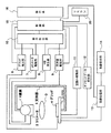
図1は本発明の第1の実施形態のX線画像診断装置の概略構成を示す模式図である。
X線画像診断装置は、X線源1と、X線源1からのX線の照射方向に配置されるX線絞り(「コリメータ」ともいう)2と、X線源1と対向配置されるFPD3と、FPD3のX線入力面に配置される散乱線除去グリッド(単に「グリッド」という)4と、X線源1とFPD3とを支持する支持器5と、グリッド4の挿抜を検出するグリッド検出部6と、コリメータ2を駆動するコリメータ駆動部7と、X線源1に電源を供給するX線発生器8と、支持器5を駆動する支持器駆動部9と、グリッド検出部6、コリメータ駆動部7、X線発生器8及び支持器駆動部9と信号伝達可能に接続される動作検出部10と、FPD3と信号伝達可能に接続される空読み駆動部11、オフセットデータ更新部12及び画像処理部13と、画像処理部13と信号伝達可能に接続される画像表示部14と、グリッド検出部6、コリメータ駆動部7、X線発生器8、支持器駆動部9、動作検出部10、空読み駆動部11、オフセットデータ更新部12及び画像処理部13と信号伝達可能に接続される制御部15と、制御部15と信号伝達可能に接続される操作卓16と、を有している。
Hereinafter, embodiments of the X-ray image diagnostic apparatus of the present invention will be described with reference to the drawings.
(First embodiment)
FIG. 1 is a schematic diagram showing a schematic configuration of an X-ray image diagnostic apparatus according to a first embodiment of the present invention.
The X-ray diagnostic imaging apparatus is disposed opposite to the X-ray source 1, the X-ray diaphragm (also referred to as “collimator”) 2 disposed in the X-ray irradiation direction from the X-ray source 1, and the X-ray source 1. FPD3, scattered radiation removal grid (simply called “grid”) 4 placed on the X-ray input surface of FPD3, support 5 that supports X-ray source 1 and FPD3, and grid that detects insertion and removal of grid 4 A detection unit 6, a
X線源1は、X線管であり、被検者OにX線を照射する。コリメータ2はX線源1より照射されるX線照射を被検者Oの撮影部位のみに限定するために、その撮影部位以外のX線を遮蔽する。FPD3は被検者の透過X線をX線画像として検出する。グリッド4はFPD3に入射されるX線のうちの散乱X線成分を除去して、被検者Oを直進して透過したX線のみFPD3に入射されるようにする。支持器5はX線源1とFPD3を支持しながら、被検者Oに対して様々な方向から撮影できるようにその所望の撮影位置を設定することができる。
The X-ray source 1 is an X-ray tube and irradiates the subject O with X-rays. The collimator 2 shields X-rays other than the imaging region in order to limit the X-ray irradiation irradiated from the X-ray source 1 only to the imaging region of the subject O. The FPD 3 detects the transmitted X-ray of the subject as an X-ray image. The
クリッド検出器6はグリッド4の挿抜を検出すると共に、挿入されているグリッド4の種類(様々な集束距離やグリッドの格子間隔がある)も検出し、その検出信号を動作検出部10及び制御部15に伝送する。コリメータ駆動部7は図示省略したモータ等の公知の駆動手段でコリメータ2を駆動すると共に、コリメータ2がX線照射域のどこまで挿入されているかその位置を検出する機能を有している。この位置検出は図示省略したモータ等に取り付けられたエンコーダによって行われる。X線発生器8は設定されたX線管に印加する電圧(管電圧)、X線管に流す電流(管電流)、X線照射時間などのパラメータに基づいてX線源1に電源を供給する。支持器駆動部9は図示省略したモータ等の公知の駆動手段で支持器5を駆動すると共に、支持器5が現在位置及び移動後の位置を検出する機能を有している。この位置検出は図示省略したモータ等に取り付けられたエンコーダによって行われる。
The Clid detector 6 detects the insertion / extraction of the
動作検出部10は、次の検出信号や電圧の少なくとも一つを検出したならば、制御部15に動作検出信号を送信する。
(1)クリッド検出器6によりグリッドが抜かれたり新たに挿入されたりしたことを示す 検出信号(空読み、オフセットデータ更新をON)
(2)コリメータ駆動部7によりコリメータ2が移動されたことを示す検出信号(空読み、オフセットデータ更新をON)
(3)X線発生器8によりX線源(X線管)1に印加された電圧(空読み、オフセットデータ更新をOFF)
(4)支持器駆動部9により支持器5が移動されたことを示す検出信号(空読み、オフセットデータ更新をON)
The
(1) Detection signal indicating that the grid has been removed or newly inserted by the Clid detector 6 (empty reading, offset data update is ON)
(2) Detection signal indicating that collimator 2 has been moved by collimator drive unit 7 (empty reading, offset data update is ON)
(3) Voltage applied to X-ray source (X-ray tube) 1 by X-ray generator 8 (empty reading and offset data update OFF)
(4) Detection signal indicating that the support device 5 has been moved by the support device drive unit 9 (empty reading, offset data update is ON)
空読み駆動部11は、制御部15からの制御信号に基づきFPD3の空読み動作を行う。
ここで、空読み動作について説明する。FPD3は半導体で形成された構造上の問題により、撮影などに用いられたときに半導体検出素子に電荷がしばらくの間残る。その残った電荷は残像現象の原因となる。そこで、残像の除去は正規に画像を読み出した後、さらに残った電荷を読み出す。空読み動作とは前記残った電荷の読出しを意味している。
オフセットデータ更新部12は、制御部15からの制御信号に基づきFPD3からその暗電流量を読み出し、その読み出された暗電流量によって従前にメモリに記憶されていたオフセット補正データを更新する。
The idle
Here, the idle reading operation will be described. Due to the structural problem of the
The offset
画像処理部13はFPD3より出力される画像データを画像処理する。この画像処理の例は、診断部位の画素値分布が画像表示部14にて最適な表示階調となるように変換する。
画像表示部14は画像処理部13によって画像処理された画像データを表示する。
The
The
制御部15は、次の各種動作を行う。
(1)制御部15は、グリッド検出部6のグリッド4の挿抜、グリッド4の種類の検出信号を受信する。
(2)制御部15は、コリメータ駆動部7によってコリメータ2の位置を検出し、その検出された位置から所望の位置へ駆動制御させる。
(3)制御部15は、設定入力された管電圧等のパラメータに基づきX線発生器8によってX線源1を動作させる。
(4)制御部15は、設定入力された支持器5の設定位置に基づき支持器駆動部9によって支持器5の位置を検出し、その設定された位置へ駆動制御させる。
(5)制御部15は、動作検出部10からの動作検出信号に基づき空読み駆動部11にFPD3を空読みさせる。
(6)制御部15は、動作検出部10からの動作検出信号に基づきオフセットデータ更新部12にFPD3のオフセットデータを更新させる。
(7)制御部15は、画像処理部13にFPD3から出力される画像データを画像処理させる。
操作卓16は、検者が各種パラメータを設定入力する。各種パラメータは、コリメータ2の挿入位置、X線源1のX線発生条件、支持器5の位置、画像処理部13の画像処理条件などである。
The
(1) The
(2) The
(3) The
(4) The
(5) The
(6) The
(7) The
The
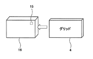
図2は図1のグリッド検出部6の例を示す図である。
グリッド検出部6は、グリッド4を挿入可能なグリッド保持部17と、グリッド4に取り付けられたバーコード部18と、保持部17に設けられるバーコードリーダ部19とを有している。
グリッド保持部17はグリッド4を収容して保持する。バーコード部18はグリッド4の種類の情報が記録されている。グリッドの種類はX線の集束距離と格子間隔によって規定される。例えば、集束距離が180cmで格子間隔が80本/cmなどがある。バーコードリーダ部19は、グリッド4が保持部17から抜けた状態であるか、挿入された状態であるか否かを判定すると共に、グリッド4を保持部17に挿入する際に、グリッド4に設けられたバーコード18をスキャンし、そのバーコード18にある情報を読み出し、グリッド4の種類を認識し、動作検出部10及び制御部15にグリッド4の挿抜及び種類の情報を伝送する。また、グリッド4がグリッド保持部17から抜く際にはバーコードを逆読みし、グリッド4がグリッド保持部17から抜けたことを認識してもよい。
ここでは、グリッドの挿抜及び種類の検出をバーコードで説明したが、これらの検出はバーコードに限らず、グリッドの挿抜及び種類の検出が機能する方法であればその方法は何であってもよい。
FIG. 2 is a diagram illustrating an example of the grid detection unit 6 of FIG.
The grid detection unit 6 includes a grid holding unit 17 into which the
The grid holding unit 17 accommodates and holds the
Here, the insertion / extraction of the grid and the detection of the type are described with the barcode, but these detections are not limited to the barcode, and any method may be used as long as the method of insertion / extraction of the grid and the detection of the type functions. .
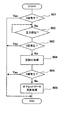
図3は図1のX線画像診断装置の処理例を示すフローチャートである。
(ステップ301)
動作検出部10はX線発生器8を監視し、X線が発生するか否かを検出する。制御部15は動作検出部10によってX線が発生していることを検出すれば処理を終了し、X線が発生していないことを検出すれば次のステップに進む。
(ステップ302)
動作検出部10はグリッド検出部6、コリメータ駆動部7及び支持器駆動部9を監視し、これらの少なくとも一つが動作しているか否かを検出する。制御部15は動作検出部10の検出結果が少なくとも一つが動作していれば次のステップに進み、一つも動作していなければ動作するまで待機する。
(ステップ303)
動作検出部10はX線発生器8を常に監視しており、制御部15は動作検出部10によってX線が発生していることを動作検出部10によって検出されれば処理を終了する。X線が発生していなければ次のステップに進む。なお、フローチャートが複雑になるので省略したが、前ステップにおいて上記少なくとも一つ動作の待機中であってもX線が発生すれば処理を終了する。
FIG. 3 is a flowchart showing a processing example of the X-ray image diagnostic apparatus of FIG.
(Step 301)
The
(Step 302)
The
(Step 303)
The
(ステップ304)
制御部15は空読み駆動部11にFPD3の空読みを実行させる。
(ステップ305)
動作検出部10はX線発生器8を常に監視しており、制御部15は動作検出部10によってX線が発生していることを動作検出部10によって検出されれば処理を終了する。X線が発生していなければ次のステップに進む。
(ステップ306)
制御部15はオフセットデータ更新部12にFPD3のオフセットデータの更新を実行させ、処理を終了する。オフセットデータの更新は新たに得たオフセットデータを今までのオフセットデータに加算し、その加算値を平均する。
(Step 304)
The
(Step 305)
The
(Step 306)
The
本実施形態のX線画像診断装置は、以上説明した構成と手順によれば、X線を照射していないタイミングをFPDの補正処理のために有効活用できる。 According to the configuration and procedure described above, the X-ray diagnostic imaging apparatus according to the present embodiment can effectively utilize the timing when X-rays are not irradiated for FPD correction processing.
(第2の実施形態)
図4は本発明の第2の実施形態のX線画像診断装置の概略構成を示す模式図である。
第1の実施形態のX線画像診断装置との相違点は、リモコン20が制御部15に接続されたことである。
通常、X線画像診断装置が設置してある部屋の外に設置された操作卓16の位置まで戻って被検者の撮影部位やX線照射域の設定するのでは作業効率が悪いので、リモコン20によってコリメータ2の位置と支持器5の位置決めをすれば、検者は被検者に近づいた状態で撮影位置を設定できるから、作業効率が向上するためにリモコン20は設けられている。
(Second Embodiment)
FIG. 4 is a schematic diagram showing a schematic configuration of the X-ray image diagnostic apparatus according to the second embodiment of the present invention.
The difference from the X-ray image diagnostic apparatus of the first embodiment is that the
Normally, returning to the position of the
図5は図4のX線画像診断装置の処理例を示すフローチャートである。
(ステップ501)
動作検出部10はX線発生器8を監視し、X線が発生するか否かを検出する。制御部15は動作検出部10によってX線が発生していることを検出すれば処理を終了し、X線が発生していないことを検出すれば次のステップに進む。
(ステップ502)
動作検出部10はリモコン20を監視し、リモコン20が動作しているか否かを検出する。制御部15は動作検出部10の検出結果がリモコン動作であれば次のステップに進み、動作していなければ動作するまで待機する。
(ステップ503)
動作検出部10はX線発生器8を常に監視しており、制御部15は動作検出部10によってX線が発生していることを動作検出部10によって検出されれば処理を終了する。X線が発生していなければ次のステップに進む。なお、フローチャートが複雑になるので省略したが、前ステップにおいてリモコン20の動作の待機中であってもX線が発生すれば処理を終了する。
FIG. 5 is a flowchart showing a processing example of the X-ray image diagnostic apparatus of FIG.
(Step 501)
The
(Step 502)
The
(Step 503)
The
(ステップ504)
制御部15は空読み駆動部11にFPD3の空読みを実行させる。
(ステップ505)
動作検出部10はX線発生器8を常に監視しており、制御部15は動作検出部10によってX線が発生していることを動作検出部10によって検出されれば処理を終了する。X線が発生していなければ次のステップに進む。
(ステップ506)
制御部15はオフセットデータ更新部12にFPD3のオフセットデータの更新を実行させ、処理を終了する。
(Step 504)
The
(Step 505)
The
(Step 506)
The
本実施形態のX線画像診断装置は、以上説明した構成と手順によれば、実施形態1の効果と共に、リモコン動作時のX線を照射していないタイミングをFPDの補正処理のために有効活用できる。 According to the configuration and procedure described above, the X-ray diagnostic imaging apparatus according to the present embodiment effectively uses the timing at which the X-ray is not emitted during remote control operation for the FPD correction process, in addition to the effects of the first embodiment. it can.
(第3の実施形態)
図6は本発明の第3の実施形態のX線画像診断装置の概略構成を示す模式図である。
第1の実施形態のX線画像診断装置との相違点は、ドア開閉検出部21が制御部15に接続されたことである。
ドア開閉検出部21は、通常X線画像診断装置が設置してある部屋の室内外に設置されるドア22の開閉を検出する。ドア22が開かれているときはX線が発生しないときである。このX線の発生しないときにFPD3の補正処理を行う。
(Third embodiment)
FIG. 6 is a schematic diagram showing a schematic configuration of an X-ray image diagnostic apparatus according to the third embodiment of the present invention.
The difference from the X-ray diagnostic imaging apparatus of the first embodiment is that the door opening /
The door opening /
図7は図6のX線画像診断装置の処理例を示すフローチャートである。
(ステップ701)
動作検出部10はX線発生器8を監視し、X線が発生するか否かを検出する。制御部15は動作検出部10によってX線が発生していることを検出すれば処理を終了し、X線が発生していないことを検出すれば次のステップに進む。
(ステップ702)
動作検出部10はドア開閉検出部21を監視し、ドア開閉検出部21はドア22が「開」状態になっているか「閉」状態になっているかを検出する。制御部15は動作検出部10の検出結果がドア「開」状態となっていれば次のステップに進み、「閉」状態になっていれば「開」状態となるまで待機する。
(ステップ703)
動作検出部10はX線発生器8を常に監視しており、制御部15は動作検出部10によってX線が発生していることを動作検出部10によって検出されれば処理を終了する。X線が発生していなければ次のステップに進む。なお、フローチャートが複雑になるので省略したが、前ステップにおいてドア22が開となるまで待機中であってもX線が発生すれば処理を終了する。
FIG. 7 is a flowchart showing a processing example of the X-ray image diagnostic apparatus of FIG.
(Step 701)
The
(Step 702)
The
(Step 703)
The
(ステップ704)
制御部15は空読み駆動部11にFPD3の空読みを実行させる。
(ステップ705)
動作検出部10はX線発生器8を常に監視しており、制御部15は動作検出部10によってX線が発生していることを動作検出部10によって検出されれば処理を終了する。X線が発生していなければ次のステップに進む。
(ステップ706)
制御部15はオフセットデータ更新部12にFPD3のオフセットデータの更新を実行させ、処理を終了する。
(Step 704)
The
(Step 705)
The
(Step 706)
The
本実施形態のX線画像診断装置は、以上説明した構成と手順によれば、実施形態1の効果と共に、ドア22が「開」状態のタイミングをFPDの補正処理のために有効活用できる。
According to the configuration and procedure described above, the X-ray diagnostic imaging apparatus of the present embodiment can effectively utilize the timing when the
(第4の実施形態)
図8は本発明の第4の実施形態のX線画像診断装置の概略構成を示す模式図である。
第1の実施形態のX線画像診断装置との相違点は、圧力検出部23が制御部15に接続されたことである。
圧力検出部23は、FPD3の前面(X線入射側)の床面等に取り付けられた圧力センサで、被検者がFPD3の撮影可能領域にあるか否かを検出する。撮影可能領域にあるとは被検者がFPD3の側に立っていたり、車椅子の被検者がFPD3の側に座っていたりする状態を意味する。被検者がFPD3の撮影可能領域にないときはX線が発生しないときである。このX線の発生しないときにFPD3の補正処理を行う。
(Fourth embodiment)
FIG. 8 is a schematic diagram showing a schematic configuration of an X-ray image diagnostic apparatus according to the fourth embodiment of the present invention.
The difference from the X-ray diagnostic imaging apparatus of the first embodiment is that the
The
図9は図8のX線画像診断装置の処理例を示すフローチャートである。
(ステップ901)
動作検出部10はX線発生器8を監視し、X線が発生するか否かを検出する。制御部15は動作検出部10によってX線が発生していることを検出すれば処理を終了し、X線が発生していないことを検出すれば次のステップに進む。
(ステップ902)
動作検出部10は圧力検出部23を監視し、圧力検出部23は被検者がFPD3の撮影領域にあるか否かを検出する。制御部15は動作検出部10の検出結果が撮影領域にない状態になっていれば次のステップに進み、撮影領域にある状態になっていれば撮影領域にない状態になるまで待機する。
(ステップ903)
動作検出部10はX線発生器8を常に監視しており、制御部15は動作検出部10によってX線が発生していることを動作検出部10によって検出されれば処理を終了する。X線が発生していなければ次のステップに進む。なお、フローチャートが複雑になるので省略したが、前ステップにおいて撮影領域にない状態となるまで待機中であってもX線が発生すれば処理を終了する。
FIG. 9 is a flowchart showing a processing example of the X-ray image diagnostic apparatus of FIG.
(Step 901)
The
(Step 902)
The
(Step 903)
The
(ステップ904)
制御部15は空読み駆動部11にFPD3の空読みを実行させる。
(ステップ905)
動作検出部10はX線発生器8を常に監視しており、制御部15は動作検出部10によってX線が発生していることを動作検出部10によって検出されれば処理を終了する。X線が発生していなければ次のステップに進む。
(ステップ906)
制御部15はオフセットデータ更新部12にFPD3のオフセットデータの更新を実行させ、処理を終了する。
(Step 904)
The
(Step 905)
The
(Step 906)
The
本実施形態のX線画像診断装置は、以上説明した構成と手順によれば、実施形態1の効果と共に、FPD3と被検者が撮影領域にない状態のタイミングをFPDの補正処理のために有効活用できる。
According to the configuration and procedure described above, the X-ray diagnostic imaging apparatus according to the present embodiment is effective for the FPD correction process in addition to the effects of the first embodiment and the timing when the
以上説明した実施形態は、様々な変形例やそれらの組み合わせを含む。
本発明には、特許請求の範囲の各請求項に記載された発明が実施できる構成、方法、機能を有していればその全てが含まれる。
The embodiment described above includes various modifications and combinations thereof.
The present invention includes all of the configurations, methods, and functions that can implement the inventions described in the claims.
1 X線源、2 X線絞り(コリメータ)、3 X線平面検出器(FPD)、4 グリッド、5 支持器、10 動作検出部、11 空読み駆動部、12 オフセットデータ更新部、13 画像処理部、14 画像表示部 1 X-ray source, 2 X-ray aperture (collimator), 3 X-ray flat panel detector (FPD), 4 grid, 5 supporter, 10 motion detector, 11 idle reading drive, 12 offset data updater, 13 image processing , 14 Image display
Claims (3)
前記X線源からのX線照射動作の有無と、圧力センサによって前記被検者が前記X線平面検出器の撮影可能領域にいるか否か、を検出する動作検出部を有し、前記動作検出部によって、X線照射動作が無く、さらに前記被検者がX線平面検出器の撮影可能領域にいないことを検出した場合、前記X線平面検出器の出力信号の補正処理を行ない、前記補正された出力信号をX線画像として前記表示手段に表示することを特徴とするX線画像診断装置。 An X-ray source that irradiates the subject with X-rays, an X-ray diaphragm that limits the X-rays irradiated by the X-ray source to a predetermined field of view of the subject, and the X-ray source that is disposed opposite to the X-ray source An X-ray flat detector for detecting transmitted X-rays of the subject, and a grid that is disposed on the X-ray incident surface of the X-ray flat detector and removes scattered X-ray components from the transmitted X-rays of the subject And a supporter that supports the X-ray source and the X-ray flat panel detector while maintaining an opposing arrangement relationship, and display means for displaying an output signal of the X-ray flat panel detector as an X-ray image. In the X-ray image diagnostic apparatus,
An operation detection unit that detects presence or absence of an X-ray irradiation operation from the X-ray source and whether or not the subject is in an imageable region of the X-ray flat panel detector by a pressure sensor; When it is detected that the X-ray irradiation operation is not performed and the subject is not in the radiographable region of the X-ray flat panel detector, the output signal of the X-ray flat panel detector is corrected and the correction is performed. An X-ray diagnostic imaging apparatus, wherein the output signal is displayed on the display means as an X-ray image.
Priority Applications (1)
| Application Number | Priority Date | Filing Date | Title |
|---|---|---|---|
| JP2005058309A JP4651412B2 (en) | 2005-03-03 | 2005-03-03 | X-ray diagnostic imaging equipment |
Applications Claiming Priority (1)
| Application Number | Priority Date | Filing Date | Title |
|---|---|---|---|
| JP2005058309A JP4651412B2 (en) | 2005-03-03 | 2005-03-03 | X-ray diagnostic imaging equipment |
Publications (3)
| Publication Number | Publication Date |
|---|---|
| JP2006239101A JP2006239101A (en) | 2006-09-14 |
| JP2006239101A5 JP2006239101A5 (en) | 2008-02-28 |
| JP4651412B2 true JP4651412B2 (en) | 2011-03-16 |
Family
ID=37046091
Family Applications (1)
| Application Number | Title | Priority Date | Filing Date |
|---|---|---|---|
| JP2005058309A Expired - Fee Related JP4651412B2 (en) | 2005-03-03 | 2005-03-03 | X-ray diagnostic imaging equipment |
Country Status (1)
| Country | Link |
|---|---|
| JP (1) | JP4651412B2 (en) |
Families Citing this family (6)
| Publication number | Priority date | Publication date | Assignee | Title |
|---|---|---|---|---|
| JP5311328B2 (en) * | 2008-04-23 | 2013-10-09 | ジーイー・メディカル・システムズ・グローバル・テクノロジー・カンパニー・エルエルシー | Medical imaging system |
| JP5396814B2 (en) * | 2008-10-28 | 2014-01-22 | コニカミノルタ株式会社 | Radiation imaging system |
| JP5442381B2 (en) * | 2009-09-30 | 2014-03-12 | ジーイー・メディカル・システムズ・グローバル・テクノロジー・カンパニー・エルエルシー | Medical imaging system |
| CN103096798A (en) * | 2010-09-08 | 2013-05-08 | 株式会社日立医疗器械 | X-ray diagnostic system |
| JP5713864B2 (en) * | 2011-09-30 | 2015-05-07 | 富士フイルム株式会社 | Radiography equipment |
| JP5768932B2 (en) * | 2012-03-21 | 2015-08-26 | 株式会社島津製作所 | Radiography equipment |
Citations (3)
| Publication number | Priority date | Publication date | Assignee | Title |
|---|---|---|---|---|
| JP2002159481A (en) * | 2000-11-22 | 2002-06-04 | Hitachi Medical Corp | X-ray imaging apparatus |
| JP2002336227A (en) * | 2001-04-17 | 2002-11-26 | Siemens Ag | X-ray apparatus |
| JP2002369084A (en) * | 2001-06-05 | 2002-12-20 | Canon Inc | Imaging device and method, radiographic device and method, storage medium, and program |
Family Cites Families (1)
| Publication number | Priority date | Publication date | Assignee | Title |
|---|---|---|---|---|
| JPH02173600A (en) * | 1988-12-27 | 1990-07-05 | Nec Corp | Medical radiation shielding chamber |
-
2005
- 2005-03-03 JP JP2005058309A patent/JP4651412B2/en not_active Expired - Fee Related
Patent Citations (3)
| Publication number | Priority date | Publication date | Assignee | Title |
|---|---|---|---|---|
| JP2002159481A (en) * | 2000-11-22 | 2002-06-04 | Hitachi Medical Corp | X-ray imaging apparatus |
| JP2002336227A (en) * | 2001-04-17 | 2002-11-26 | Siemens Ag | X-ray apparatus |
| JP2002369084A (en) * | 2001-06-05 | 2002-12-20 | Canon Inc | Imaging device and method, radiographic device and method, storage medium, and program |
Also Published As
| Publication number | Publication date |
|---|---|
| JP2006239101A (en) | 2006-09-14 |
Similar Documents
| Publication | Publication Date | Title |
|---|---|---|
| JP4651412B2 (en) | X-ray diagnostic imaging equipment | |
| US7433445B2 (en) | Apparatus for and method of capturing radiation image | |
| US7172340B2 (en) | X-ray imaging apparatus and method for moving X-ray detector | |
| WO2015067536A1 (en) | X-ray imaging device and auxiliary positioning system thereof | |
| US20070009092A1 (en) | X-ray image diagnostic device | |
| EP2095770A1 (en) | Radiation image capturing system, radiation image capturing method and program | |
| JP2007105345A (en) | X-ray diagonostic imaging device | |
| US9186119B2 (en) | Radiation image capturing system, radiation detecting apparatus, image capturing base and radiation image capturing method | |
| US8475043B2 (en) | Radiation imaging apparatus and processing method therefor | |
| JP4772355B2 (en) | X-ray diagnostic equipment | |
| US8086061B2 (en) | Image processing device and image processing method | |
| JP4828854B2 (en) | X-ray diagnostic apparatus and its management apparatus | |
| JP2008245999A (en) | Radiographic equipment | |
| US8030616B2 (en) | Radiation image capturing system, sorting apparatus for sorting image capturing instruction information, program and radiation image capturing method | |
| JP2010201103A (en) | X-ray image diagnostic device | |
| JPWO2008072312A1 (en) | Radiation imaging apparatus and radiation detection signal processing method | |
| JP2006122121A (en) | Radiographic imaging system | |
| US11009610B2 (en) | Radiation detection system, radiation output device, and radiation detection device | |
| JP4522437B2 (en) | X-ray imaging apparatus and imaging method | |
| JP2016030089A (en) | Imaging control device, imaging control method, and program | |
| JP5383023B2 (en) | MEDICAL DEVICE AND MESSAGE OUTPUT DEVICE | |
| JP2012079540A (en) | Mobile x-ray apparatus and method of x-ray radiography | |
| JP2009028332A (en) | Cassette and radiation image photographing system | |
| JP2010046130A (en) | Radiation image photographing system, radiation converter and photographing stand | |
| JP2008073424A (en) | X-ray diagnostic apparatus |
Legal Events
| Date | Code | Title | Description |
|---|---|---|---|
| A521 | Request for written amendment filed |
Free format text: JAPANESE INTERMEDIATE CODE: A523 Effective date: 20080111 |
|
| A621 | Written request for application examination |
Free format text: JAPANESE INTERMEDIATE CODE: A621 Effective date: 20080111 |
|
| A977 | Report on retrieval |
Free format text: JAPANESE INTERMEDIATE CODE: A971007 Effective date: 20100521 |
|
| A131 | Notification of reasons for refusal |
Free format text: JAPANESE INTERMEDIATE CODE: A131 Effective date: 20100607 |
|
| A521 | Request for written amendment filed |
Free format text: JAPANESE INTERMEDIATE CODE: A523 Effective date: 20100721 |
|
| A131 | Notification of reasons for refusal |
Free format text: JAPANESE INTERMEDIATE CODE: A131 Effective date: 20100906 |
|
| A521 | Request for written amendment filed |
Free format text: JAPANESE INTERMEDIATE CODE: A523 Effective date: 20101026 |
|
| TRDD | Decision of grant or rejection written | ||
| A01 | Written decision to grant a patent or to grant a registration (utility model) |
Free format text: JAPANESE INTERMEDIATE CODE: A01 Effective date: 20101124 |
|
| A01 | Written decision to grant a patent or to grant a registration (utility model) |
Free format text: JAPANESE INTERMEDIATE CODE: A01 |
|
| A61 | First payment of annual fees (during grant procedure) |
Free format text: JAPANESE INTERMEDIATE CODE: A61 Effective date: 20101214 |
|
| R150 | Certificate of patent or registration of utility model |
Ref document number: 4651412 Country of ref document: JP Free format text: JAPANESE INTERMEDIATE CODE: R150 Free format text: JAPANESE INTERMEDIATE CODE: R150 |
|
| FPAY | Renewal fee payment (event date is renewal date of database) |
Free format text: PAYMENT UNTIL: 20131224 Year of fee payment: 3 |
|
| S111 | Request for change of ownership or part of ownership |
Free format text: JAPANESE INTERMEDIATE CODE: R313111 |
|
| S533 | Written request for registration of change of name |
Free format text: JAPANESE INTERMEDIATE CODE: R313533 |
|
| R350 | Written notification of registration of transfer |
Free format text: JAPANESE INTERMEDIATE CODE: R350 |
|
| LAPS | Cancellation because of no payment of annual fees |