JP4651307B2 - Illumination environment reproduction apparatus and method, and video reproduction apparatus - Google Patents
Illumination environment reproduction apparatus and method, and video reproduction apparatus Download PDFInfo
- Publication number
- JP4651307B2 JP4651307B2 JP2004156082A JP2004156082A JP4651307B2 JP 4651307 B2 JP4651307 B2 JP 4651307B2 JP 2004156082 A JP2004156082 A JP 2004156082A JP 2004156082 A JP2004156082 A JP 2004156082A JP 4651307 B2 JP4651307 B2 JP 4651307B2
- Authority
- JP
- Japan
- Prior art keywords
- lighting
- signal
- video
- illumination
- reproduction
- Prior art date
- Legal status (The legal status is an assumption and is not a legal conclusion. Google has not performed a legal analysis and makes no representation as to the accuracy of the status listed.)
- Expired - Fee Related
Links
Images


Classifications
-
- Y—GENERAL TAGGING OF NEW TECHNOLOGICAL DEVELOPMENTS; GENERAL TAGGING OF CROSS-SECTIONAL TECHNOLOGIES SPANNING OVER SEVERAL SECTIONS OF THE IPC; TECHNICAL SUBJECTS COVERED BY FORMER USPC CROSS-REFERENCE ART COLLECTIONS [XRACs] AND DIGESTS
- Y02—TECHNOLOGIES OR APPLICATIONS FOR MITIGATION OR ADAPTATION AGAINST CLIMATE CHANGE
- Y02B—CLIMATE CHANGE MITIGATION TECHNOLOGIES RELATED TO BUILDINGS, e.g. HOUSING, HOUSE APPLIANCES OR RELATED END-USER APPLICATIONS
- Y02B20/00—Energy efficient lighting technologies, e.g. halogen lamps or gas discharge lamps
- Y02B20/40—Control techniques providing energy savings, e.g. smart controller or presence detection
Landscapes
- Circuit Arrangement For Electric Light Sources In General (AREA)
- Television Signal Processing For Recording (AREA)
- Color Television Image Signal Generators (AREA)
- Controls And Circuits For Display Device (AREA)
- Signal Processing For Digital Recording And Reproducing (AREA)
Description
本発明は、映像信号及び音声信号の再生時に、これら映像信号及び音声信号が取得されたときの撮影時の照明環境に関する照明環境情報に基づいて照明装置をコントロールすることにより、撮影時の照明環境を再現可能とする技術に関する。 The present invention controls the illumination environment at the time of shooting by controlling the lighting device based on the lighting environment information regarding the lighting environment at the time of shooting when the video signal and the audio signal are acquired at the time of reproducing the video signal and the audio signal. It is related to the technology that can reproduce.
例えば、特許文献1には、ビデオ撮影時の情報を記録し、ビデオ再生時に撮影時の環境を再現できるようにしたビデオ記録装置及び再生装置が開示されている。このビデオ記録再生装置は、ビデオ撮影時に、CCD及びマイクロフォンによって映像及び音声を収録し、それぞれ所定の信号処理を施して磁気テープに記録する。また、ビデオ撮影と同時に環境検出装置によって撮影時の現場の環境を検出して環境情報を取得する。取得した環境情報は、回路で所定の信号処理を施して磁気テープの所定の領域に記録される。
For example,
そして観客等に対して記録情報を再生する時には、モニタやスピーカで映像/音声を再現すると共に、例えばエアコンによって温度,湿度を再現し、送風機によって風向,風速を再現し、伸縮自在な支柱を制御する支柱制御装置によって観客が座る椅子が設置された小部屋の傾斜,加速度などを再現し、照明灯によって照度を再現する。こうして、映像/音声と共に撮影時の現場の環境が再現されるため、観客は、より高い現実感を体験することができる。
ところが、上記特許文献1の技術では、色温度照度計を利用して照度情報や色温度情報を検出することは可能であるが、色度値の情報がないため、舞台照明等で利用されるRGB3原色を再現した照明の検出をすることが不可能である。また、たとえ色温度照度計によって色温度情報を検出したとしても、色フィルター付きの照明灯の具体的な制御方法が記載されてなく、撮影時の照明の色みを再現することができない。However, in the technique of
本発明は、上記の問題点に鑑みてなされたものであり、その目的は、撮影情報再生時に、撮影時の周囲光に関する環境照明情報に基づいて照明装置をコントロールすることにより、撮影時の周囲光の色みを忠実に再現することができ、あたかもその場にいるかのような高臨場感を感じることができるようにした照明環境再現装置及び方法、映像再生装置を提供することにある。 The present invention has been made in view of the above-described problems, and its purpose is to control the lighting device based on the environmental lighting information related to ambient light at the time of shooting when reproducing shooting information, thereby An object of the present invention is to provide an illumination environment reproduction device and method, and an image reproduction device that can faithfully reproduce the color of light and feel a high sense of presence as if the person is on the spot.
第1の技術手段は、映像信号及び音声信号の再生時に、前記映像信号及び音声信号が取得されたときの撮影時の照明環境に関する照明環境情報に基づいて、照明装置をコントロールすることにより、前記撮影時の照明環境を再現する照明環境再現装置において、前記照明装置として、RGB値で制御されるカラー照明装置を利用する場合には、色度値で表される前記照明環境情報をRGB値に変換して前記照明装置に出力し、前記照明装置として、色温度値で制御される照明装置を利用する場合には、色度値で表される前記照明環境情報を色温度値に変換して前記照明装置に出力することを特徴とする。 The first technical means controls the lighting device based on the lighting environment information related to the lighting environment at the time of shooting when the video signal and the audio signal are acquired during the reproduction of the video signal and the audio signal. In a lighting environment reproduction device that reproduces a lighting environment at the time of shooting, when a color lighting device controlled by RGB values is used as the lighting device , the lighting environment information represented by chromaticity values is converted to RGB values. When the lighting device controlled by a color temperature value is used as the lighting device, the lighting environment information represented by the chromaticity value is converted into a color temperature value. It outputs to the said illuminating device, It is characterized by the above-mentioned .
第2の技術手段は、第1の技術手段に記載の照明環境再現装置と、前記映像信号に再生処理を施して映像表示する表示手段と、前記音声信号に再生処理を施して音声出力する音声出力手段とを有することを特徴とする。 The second technical means includes the illumination environment reproduction device according to the first technical means, display means for performing reproduction processing on the video signal and displaying video, and audio for performing reproduction processing on the audio signal and outputting sound. Output means .
第3の技術手段は、映像信号及び音声信号の再生時に、前記映像信号及び音声信号が取得されたときの撮影時の照明環境に関する照明環境情報に基づいて、照明装置をコントロールすることにより、前記撮影時の照明環境を再現する照明環境再現方法において、前記照明装置として、RGB値で制御されるカラー照明装置を利用する場合には、色度値で表される前記照明環境情報をRGB値に変換して前記照明装置に出力し、前記照明装置として、色温度値で制御される照明装置を利用する場合には、色度値で表される前記照明環境情報を色温度値に変換して前記照明装置に出力することを特徴とする。 The third technical means controls the lighting device based on the lighting environment information related to the lighting environment at the time of shooting when the video signal and the audio signal are acquired during the reproduction of the video signal and the audio signal. In a lighting environment reproduction method for reproducing a lighting environment at the time of shooting, when a color lighting device controlled by RGB values is used as the lighting device , the lighting environment information represented by chromaticity values is converted to RGB values. When the lighting device controlled by a color temperature value is used as the lighting device, the lighting environment information represented by the chromaticity value is converted into a color temperature value. It outputs to the said illuminating device, It is characterized by the above-mentioned .
本発明によれば、撮影情報再生時に、撮影時の周囲光に関する環境照明情報に基づいて照明装置をコントロールすることにより、撮影時の周囲光の色みを忠実に再現することができ、あたかもその場にいるかのような高臨場感を感じることが可能となる。 According to the present invention, at the time of photographing information reproduction, by controlling the illumination device on the basis of the ambient light information on ambient light shooting Kageji, can be faithfully reproduced color only ambient light at the time of shooting, as if It is possible to feel a high sense of presence as if you were on the spot .
図1は、本発明による映像記録装置の一実施形態を示すブロック図である。撮像装置1は、例えばズームレンズ,フォーカスレンズ,絞りなどから成る光学系とCCDによる撮像素子とからなり、その光学系を介してCCDに被写体像が入射される。CCDに入射された被写体像は、電気信号に変換されて映像信号とされ、A/D変換器2に供給されてディジタル信号に変換される。
FIG. 1 is a block diagram showing an embodiment of a video recording apparatus according to the present invention. The
A/D変換器2でディジタル信号に変換された映像信号は、エンコーダ3に供給され、圧縮符号化される。エンコーダ3における圧縮符号化方式としては、MPEG−2,MPEG−4、MPEG−4 ASP、JPEG、Motion−JPEG、H.263、H.264などが適用できるが、これらに限定されず適宜最適な圧縮符号化方式を採用することができる。エンコーダ3で圧縮符号化された映像信号は、ディジタル信号処理回路8に供給される。
The video signal converted into a digital signal by the A /
一方、撮影時の音声はマイクロフォン4によって電気信号に変換され音声信号とされる。この音声信号はA/D変換器5に供給され、例えば所定のサンプリング周波数でサンプリングされディジタル信号に変換される。このディジタル信号に変換された音声信号は、ディジタル信号処理回路8に供給される。
On the other hand, the sound at the time of photographing is converted into an electric signal by the
上記のCCDを備えた撮像装置1及びマイクロフォン4と、これらの信号の処理系は、例えばビデオカメラやディジタルカメラのムービー機能等に代表されるように、映像の取得が可能なものとして構成され、互いの信号の同期が取られている。
The
色彩計6は、上述の撮像装置1とマイクロフォン4とを用いた映像の撮影において、撮影時の周囲の照明環境の明るさ及び色情報といった照明信号を測定するための装置である。例えば屋外で撮影を行う場合には、色彩計6によって周囲の明るさ及び色情報といった照明環境情報が取得される。色彩計6が取得した照明環境情報は、アナログ信号あるいはディジタル信号として外部に出力することができる。ここでは、色彩計6から出力される出力信号は、マイクロプロセッサから成るA/D,MPU部7に供給される。このA/D,MPU部7は、A/D変換機能を有し、アナログ信号が入力したときには、A/D変換機能によりディジタル信号に変換される。
Colorimeter 6, in the imaging of the image with the
ここで色彩計6からの出力信号は、A/D,MPU部7に対して連続的に供給されるが、A/D,MPU部7からは所定の間隔で信号出力される。ここではA/D,MPU部7をコントロールすることにより、例えば、ビデオ信号数フレーム毎に1回の信号出力を行うようにする。A/D,MPU部7から所定間隔で出力された信号は、ディジタル信号処理回路8に供給される。
Here, the output signal from the colorimeter 6 is continuously supplied to the A / D and
上述の処理によって、ディジタル信号処理回路8には、映像信号,音声信号,照明信号がそれぞれディジタル信号化されて供給されることになる。例えば映像信号では圧縮符号化といった所定の処理を施され、ディジタル信号処理回路8に供給される。ディジタル信号処理回路8に供給されたこれらの信号は、多重化され、誤り訂正符号の付加などの所定の信号処理が行われ、撮影情報記録装置9に供給される。 Through the above processing, the digital signal processing circuit 8 is supplied with the video signal, the audio signal, and the illumination signal as digital signals. For example, the video signal is subjected to predetermined processing such as compression coding and supplied to the digital signal processing circuit 8. These signals supplied to the digital signal processing circuit 8 are multiplexed, subjected to predetermined signal processing such as addition of an error correction code, and supplied to the photographing information recording device 9.
撮影情報記録装置9では、供給された信号に対して記録符号化や変調などの記録信号処理が施され、例えば磁気テープのような記録媒体に記録される。磁気テープ上に記録が行われる場合は、映像信号と音声信号の記録と合わせて、磁気テープ上にサブコードエリアが確保され、照明信号がメタデータとして記録される。勿論、記録媒体としては上記の磁気テープに限定されることはなく、磁気ディスクや光ディスク、光磁気ディスク等のディスク媒体や、他の記録媒体を適宜適用することができる。 In the photographic information recording device 9, the supplied signal is subjected to recording signal processing such as recording encoding and modulation, and recorded on a recording medium such as a magnetic tape. When recording is performed on the magnetic tape, a subcode area is secured on the magnetic tape together with recording of the video signal and the audio signal, and the illumination signal is recorded as metadata. Of course, the recording medium is not limited to the magnetic tape described above, and a disk medium such as a magnetic disk, an optical disk, or a magneto-optical disk, and other recording media can be appropriately applied.
図2は、本発明による映像再生装置の一実施形態を示すブロック図である。本実施形態の映像再生装置は、上記図1に示す映像記録装置によって記録された信号を入力し、各信号毎に再生処理して出力を行う再生装置である。
撮影情報入力部10は、上述のようにディジタル映像信号及びディジタル音声信号とともにディジタル照明信号が多重化されて記録された記録媒体から、その多重化信号が入力される。すなわち、撮影情報入力部10は、上記記録媒体から信号を読み取る読み取り装置であってもよく、また、上記のような多重化信号を外部から入力する入力インターフェースであってもよい。
また映像再生装置に、図1に示すごとくの映像記録装置で取得された多重化信号を入力し、固定磁気ディスク等の記録媒体に記録させる記録装置を備えてもよい。この場合、撮影情報入力部10は、その記録装置から多重化信号を読み出して、ディジタル信号処置回路11に出力する。
FIG. 2 is a block diagram showing an embodiment of a video reproduction apparatus according to the present invention. The video playback apparatus according to the present embodiment is a playback apparatus that inputs signals recorded by the video recording apparatus shown in FIG. 1 and performs playback processing for each signal and outputs the signals.
The photographic
Further, the video reproduction apparatus may be provided with a recording apparatus for inputting a multiplexed signal acquired by the video recording apparatus as shown in FIG. 1 and recording the multiplexed signal on a recording medium such as a fixed magnetic disk. In this case, the imaging
映像再生装置において、撮影情報入力部10で入力された信号は、ディジタル信号処理回路11に供給される。ディジタル信号処理回路11では、供給された再生信号に対して誤り訂正などの処理が施され、記録時に多重化されたディジタル映像信号,ディジタル音声信号,及びディジタル照明信号にそれぞれ分離される。
In the video reproduction apparatus, the signal input from the photographing
ディジタル信号処理回路11にて分離された信号のうち、ディジタル映像信号はデコーダ12に供給されて圧縮解除された後、D/A変換器13に供給されアナログ映像信号に変換される。このアナログ信号は、本発明の表示手段として機能する表示装置14に送られて映像として再生される。
Of the signals separated by the digital
また、ディジタル信号処理回路11で分離された信号のうち、ディジタル音声信号はD/A変換器15に供給され、アナログ信号に変換されてアナログ音声信号とされる。このアナログ音声信号は、スピーカ16で音声として再生される。スピーカ16は、本発明の音声出力手段として機能する。
Of the signals separated by the digital
さらに、ディジタル信号処理回路11で分離された信号のうち、照明信号は、MPU,D/A部17に供給される。このMPU,D/A部17はマイクロプロセッサから成り、D/A変換機能を有する。MPU,D/A部17に入力した照明信号は、色彩計の測定データより成り、MPU,D/A部17においてアナログ信号に変換される。変換されたアナログ信号は、再現用照明変換装置18に供給され、後述する再現用照明変換処理を行った後に、照明装置19に対して制御信号として供給される。照明装置19では、その制御信号に基づいて再現用照明の色を制御することにより、撮影環境の照明の色情報を再現する。上記再現用照明変換装置18は、ディジタル信号処理回路11により分離された照明環境情報に基づいて撮影時の照明環境を再現するため制御信号を生成する。
Further, among the signals separated by the digital
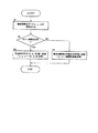
次に、上記再現用照明変換処理の手順について図3のフローチャートを用いて説明する。図2に示す再現用照明変換装置18には、撮影照明光データの一例として色度値(x,y,z)が供給される(ステップS1)。再現用照明変換装置18は、再現用照明にカラー照明を利用する場合は、色度値(x,y,z)を再現用照明のRGB値(R,G,B)に変換する(ステップS2,S3)。色度値(x,y,z)は、デバイスに依存しない均等色空間の一例であって、他の均等色空間であっても構わない。またカラー照明を利用せずに、一般の照明色温度情報を利用する場合は、色度値(x,y)から再現用照明の相関色温度値への変換を行う(ステップS2,S4)。再現用照明変換装置18は、上記の均等色空間内の色度値情報をRGB値に変換する処理と、均等色空間内の色度値情報を相関色温度値に変換する処理とのいずれかの選択が可能である。
Next, the procedure of the reproduction illumination conversion process will be described with reference to the flowchart of FIG. 2 is supplied with chromaticity values (x, y, z) as an example of photographing illumination light data (step S1). The reproduction
ここで、カラー照明の一例としてRGB3原色の照明を利用する場合について説明する。RGB3原色タイプの照明としては、カラーLEDやカラー蛍光灯などが挙げられるが、これに限られるものではない。そしてあらかじめRGBそれぞれの照明の強さを256レベルに分けて発光させ、そのときの色度値(x,y,z)を測定し、RGB−xyz変換テーブルを作成した上で再現用照明変換装置18に記憶させておく。
Here, a case where RGB three primary color illumination is used as an example of color illumination will be described. Examples of the RGB three primary color type illumination include a color LED and a color fluorescent lamp, but are not limited thereto. Then, the illumination intensity of each RGB is divided into 256 levels to emit light, the chromaticity values (x, y, z) at that time are measured, an RGB-xyz conversion table is created, and an illumination conversion apparatus for
変換テーブルの作成方法の一例を、図4に描かれた本発明をホームシアターに応用した場合を用いて説明する。図4において、部屋の中の所定位置に表示装置14及びスピーカ16が配置され、さらに再現用の照明装置19がスピーカ16の上方に配置されている。この部屋には、ソファー20が前方に向けて配置され、視聴者が座れるようになっている。そして視聴者前方の表示装置14が配置される位置に、表示装置14のかわりに図示しない標準白色板を設置し、ソファー20の位置に色彩計を設置する。
An example of a conversion table creation method will be described using the case where the present invention depicted in FIG. 4 is applied to a home theater. In FIG. 4, the
そしてスピーカ16上の照明装置19から、標準白色板に向けてRGBそれぞれの照明の強さを256レベルに分けて照射させ、その際の色度値(x,y,z)を色彩計で測定する。そして色彩計で得られた色度値をもとに、RGB−xyz変換テーブルを作成する。これにより、撮影照明光の色度値(x,y,z)に対応するカラー照明のRGB値(R,G,B)を決定することができる。
The
そして再現用照明変換装置18では、得られた色度値に基づいてRGB値を決定し、その制御信号を照明装置19に供給して発光させることによって撮影時の照明状態を再現することができる。ここでRGBからxyzへの変換はRGB−xyz変換テーブルの利用に限定されず、マトリクス変換を行っても構わない。以下はマトリクス変換の一例である。
The reproduction

図5は、本実施形態に係る再現用照明の色の範囲を示すxy色度図である。図6は、xy色度図上の色温度曲線と相関色温度曲線である。図5及び図6に示すように、再現照明用の色の範囲を、色温度曲線や相関温度曲線や現在のテレビジョンで再現できる色の範囲よりも広くすることによって、放送システムに応用する場合に撮影照明光の色の範囲を全て再現することが可能となる。 FIG. 5 is an xy chromaticity diagram showing the color range of the reproduction illumination according to this embodiment. FIG. 6 shows a color temperature curve and a correlated color temperature curve on the xy chromaticity diagram. As shown in FIG. 5 and FIG. 6, when the color range for reproduction illumination is made wider than the color temperature curve, correlation temperature curve, and color range that can be reproduced by the current television, it is applied to a broadcasting system. In addition, it is possible to reproduce the entire color range of the photographing illumination light.
また、一般の照明色温度情報を利用する場合は、上述のように色度値(x,y)から再現用照明の相関色温度値Tへの変換を行う。このときに色度値(x,y)から相関色温度値Tを求める簡易的な計算方法としては、以下に挙げるMcCamyの相関色温度変換式がある。(Color Res. Application 17,142−144(1992))
T=−437n3+3601n2−6861n+5514.31 (2)
そして、再現用照明変換装置18では、撮影照明光の色度値(x,y)に対応する相関色温度Tを有する照明を選択し、制御信号を供給して発光させることによって、撮影時の照明状態を再現することができる。
When general illumination color temperature information is used, the chromaticity value (x, y) is converted into the correlated color temperature value T of the reproduction illumination as described above. At this time, as a simple calculation method for obtaining the correlated color temperature value T from the chromaticity value (x, y), there is a McCamy correlated color temperature conversion formula described below. (Color Res. Application 17, 142-144 (1992))
T = −437n 3 + 3601n 2 −6861n + 5514.31 (2)
Then, the reproduction
上記のようなシステムにより、例えば図4に示す部屋の中のソファー20に座った視聴者に対して、映像や音声だけでなく、撮影された現場おける照明の色みが再現され、視聴者に高臨場感を提供することができる。
With the system as described above, for example, for viewers sitting on the
なお、上記の実施形態においては、撮影時に色彩計6によって照明の色みを測定し、測定された情報がA/D,MPU部7を介してディジタル信号処理回路8に供給され、撮影情報記録装置9において記録されるものとしたが、本発明はこのような構成に限定されるものではない。例えば他の例として、上述のような本発明に係るディジタル信号処理機能を有するビデオ記録装置に、ユーザによってデータの入力ができるような入力部を設け、他の撮像装置ないしマイクロフォン、及び色彩計等によって取得した環境情報を、この入力部からマニュアルで入力するようにしてもよい。この際、入力する環境情報は、実際に検出されたものでなくてもよい。
In the above-described embodiment, the color of the illumination is measured by the colorimeter 6 at the time of shooting, and the measured information is supplied to the digital signal processing circuit 8 via the A / D and
また本発明の実施形態により実施可能な映像記録方法は、撮影によって映像信号と音声信号とを取得すると共に、撮影の時の周囲光に関する照明情報を取得する照明環境情報取得ステップと、その照明情報取得ステップで取得した照明環境情報を、映像信号及び音声信号と共に記録媒体に記録する記録ステップとを有している。上記照明環境情報取得ステップは図1に示す撮像装置1,マイクロフォン4及び色彩計6によってそれぞれ映像信号,音声信号及び照明情報を取得する処理に該当する。また、記録ステップは、図1の映像信号用のA/D変換器2,エンコーダ3,音声信号用のA/D変換器5,照明情報用のA/D,MPU部7,及びこれらに所定の信号処理を施すディジタル信号処理回路8による処理と、信号処理された信号を撮影情報記録装置9記録する処理とを含む。
In addition, the video recording method that can be implemented according to the embodiment of the present invention includes a lighting environment information acquisition step of acquiring a video signal and an audio signal by shooting, and acquiring lighting information related to ambient light at the time of shooting, and the lighting information A recording step of recording the lighting environment information acquired in the acquisition step on a recording medium together with the video signal and the audio signal. The illumination environment information acquisition step corresponds to processing for acquiring a video signal, an audio signal, and illumination information by the
また、本発明の実施形態により実施可能な映像再生方法は、映像信号及び音声信号と、その映像信号及び音声信号が取得されたときの撮影時の周囲光に関する照明環境情報とが記録された記録媒体の記録情報を信号処理して分離する信号処理ステップと、その信号処理ステップによって分離されたそれぞれの信号を再生出力する再生出力ステップとを有している。そしてその再生出力ステップは、信号処理ステップにより分離された照明環境情報に基づいて撮影時の照明環境を再現するための制御信号を生成する再現用照明変換ステップを含んでいる。 In addition, the video reproduction method that can be performed according to the embodiment of the present invention includes a recording in which a video signal and an audio signal and lighting environment information related to ambient light at the time of shooting when the video signal and the audio signal are acquired are recorded. It has a signal processing step for performing signal processing to separate recording information of the medium, and a reproduction output step for reproducing and outputting each signal separated by the signal processing step. The reproduction output step includes a reproduction illumination conversion step for generating a control signal for reproducing the illumination environment at the time of photographing based on the illumination environment information separated by the signal processing step.
上記の信号処理ステップは、図2に示すディジタル信号処理回路11において、撮影情報入力部10に入力した信号に、誤り訂正などの所定の信号処理を施して、各信号を分離する処理に該当する。また上記の再生出力ステップは、ディジタル信号処理回路11によって分離された各信号の再生処理を行うステップである。ここで音声信号については、デコーダ12,D/A変換器13による処理及び表示装置14による表示出力処理を含み、また音声信号については、D/A変換器15による処理及びスピーカ16からの音声出力を含んでいる。また照明信号については、MPU,D/A部17による処理及び再現用照明変換装置18による照明制御信号の生成処理を含んでいる。照明装置は、再現用照明変換装置18にて生成された制御信号に従って照明を制御する。
The above-described signal processing step corresponds to a process of separating each signal by performing predetermined signal processing such as error correction on the signal input to the imaging
上記映像再生方法は、コンピュータによるプログラムの実行によって実現することができる。この本発明に係るプログラムはコンピュータ読み取り可能な記録媒体に記録されて、持ち運び自在な記録媒体として流通可能とし、あるいは電気通信回線を介してユーザに提供可能とすることができる。 Upper Kiutsu image reproducing method can be realized by executing a program by a computer. The program according to the present invention can be recorded on a computer-readable recording medium and can be distributed as a portable recording medium, or can be provided to a user via an electric communication line.
プログラムを記録した記録媒体は、本体と分離可能に構成される記録媒体であり、磁気テープやカセットテープ等のテープ系、フロッピー(登録商標)ディスクやハードディスク等の磁気ディスクやCD−ROM/MO/MD/DVD等の光ディスクのディスク系、ICカード(メモリカードを含む)/光カード等のカード系、あるいはマスクROM、EPROM(Erasable Programmable Read Only Memory)、EEPROM(Electrically Erasable Programmable Read Only Memory)、フラッシュROM等による半導体メモリを含めた固定的にプログラムを担持する媒体であってもよい。 The recording medium on which the program is recorded is a recording medium configured to be separable from the main body, such as a tape system such as a magnetic tape or a cassette tape, a magnetic disk such as a floppy (registered trademark) disk or a hard disk, or a CD-ROM / MO / Disk system of optical disks such as MD / DVD, card system such as IC card (including memory card) / optical card, or mask ROM, EPROM (Erasable Programmable Read Only Memory), EEPROM (Electrically Erasable Programmable Read Only Memory) flash It may be a medium that carries a fixed program including a semiconductor memory such as a ROM.
いずれの場合においても、格納されているプログラムはマイクロプロセッサがアクセスして実行させる構成であってもよいし、あるいは、マイクロコンピュータのプログラム記憶エリアに読み出されたプログラムがダウンロードされて、そのプログラムが実行される方式であってもよい。本発明の映像記録装置及び映像再生装置を、インターネットを含む通信ネットワークを接続可能なシステム構成とし、通信ネットワークからプログラムをダウンロードするようにしてもよい。このダウンロード用のプログラムは予め本体装置に格納されているか、もしくは別の記録媒体からインストールされるものであってもよい。
最後に、上述した実施の形態は、本発明の範囲を限定するものではなく、本発明の範囲内で種々の変更が可能である。
In either case, the stored program may be configured to be accessed and executed by the microprocessor, or the program read into the program storage area of the microcomputer is downloaded and the program is stored. An executed method may be used. The video recording apparatus and the video playback apparatus of the present invention may be configured to be connected to a communication network including the Internet, and the program may be downloaded from the communication network. This download program may be stored in the main apparatus in advance, or may be installed from another recording medium.
Finally, the embodiment described above does not limit the scope of the present invention, and various modifications can be made within the scope of the present invention.
1…撮像装置、2…A/D変換器、3…エンコーダ、4…マイクロフォン、5…A/D変換器、6…色彩計、7…A/D,MPU部、8…ディジタル信号処理回路、9…撮影情報記録装置、10…撮影情報入力部、11…ディジタル信号処理回路、12…デコーダ、13…D/A変換器、14…表示装置、15…D/A変換器、16…スピーカ、17…MPU,D/A部、18…再現用照明変換装置、19…照明装置、20…ソファー。
DESCRIPTION OF
Claims (3)
前記照明装置として、RGB値で制御されるカラー照明装置を利用する場合には、色度値で表される前記照明環境情報をRGB値に変換して前記照明装置に出力し、
前記照明装置として、色温度値で制御される照明装置を利用する場合には、色度値で表される前記照明環境情報を色温度値に変換して前記照明装置に出力することを特徴とする照明環境再現装置。 When playing back video and audio signals, the lighting environment at the time of shooting is reproduced by controlling the lighting device based on the lighting environment information related to the lighting environment at the time of shooting when the video and audio signals are acquired. In the lighting environment reproduction device to
When using a color lighting device controlled by RGB values as the lighting device , the lighting environment information represented by chromaticity values is converted into RGB values and output to the lighting device,
When using a lighting device controlled by a color temperature value as the lighting device, the lighting environment information represented by a chromaticity value is converted into a color temperature value and output to the lighting device. Lighting environment reproduction device.
前記映像信号に再生処理を施して映像表示する表示手段と、
前記音声信号に再生処理を施して音声出力する音声出力手段とを有することを特徴とする映像再生装置。 The lighting environment reproduction device according to claim 1;
Display means for performing reproduction processing on the video signal and displaying the video;
A video reproduction apparatus comprising: audio output means for performing reproduction processing on the audio signal and outputting the audio.
前記照明装置として、RGB値で制御されるカラー照明装置を利用する場合には、色度値で表される前記照明環境情報をRGB値に変換して前記照明装置に出力し、
前記照明装置として、色温度値で制御される照明装置を利用する場合には、色度値で表される前記照明環境情報を色温度値に変換して前記照明装置に出力することを特徴とする照明環境再現方法。 When playing back video and audio signals, the lighting environment at the time of shooting is reproduced by controlling the lighting device based on the lighting environment information related to the lighting environment at the time of shooting when the video and audio signals are acquired. In the lighting environment reproduction method to
When using a color lighting device controlled by RGB values as the lighting device , the lighting environment information represented by chromaticity values is converted into RGB values and output to the lighting device,
When using a lighting device controlled by a color temperature value as the lighting device, the lighting environment information represented by a chromaticity value is converted into a color temperature value and output to the lighting device. How to reproduce the lighting environment.
Priority Applications (1)
| Application Number | Priority Date | Filing Date | Title |
|---|---|---|---|
| JP2004156082A JP4651307B2 (en) | 2004-05-26 | 2004-05-26 | Illumination environment reproduction apparatus and method, and video reproduction apparatus |
Applications Claiming Priority (1)
| Application Number | Priority Date | Filing Date | Title |
|---|---|---|---|
| JP2004156082A JP4651307B2 (en) | 2004-05-26 | 2004-05-26 | Illumination environment reproduction apparatus and method, and video reproduction apparatus |
Publications (3)
| Publication Number | Publication Date |
|---|---|
| JP2005341122A JP2005341122A (en) | 2005-12-08 |
| JP2005341122A5 JP2005341122A5 (en) | 2006-08-03 |
| JP4651307B2 true JP4651307B2 (en) | 2011-03-16 |
Family
ID=35494191
Family Applications (1)
| Application Number | Title | Priority Date | Filing Date |
|---|---|---|---|
| JP2004156082A Expired - Fee Related JP4651307B2 (en) | 2004-05-26 | 2004-05-26 | Illumination environment reproduction apparatus and method, and video reproduction apparatus |
Country Status (1)
| Country | Link |
|---|---|
| JP (1) | JP4651307B2 (en) |
Families Citing this family (8)
| Publication number | Priority date | Publication date | Assignee | Title |
|---|---|---|---|---|
| US20090322955A1 (en) * | 2006-06-13 | 2009-12-31 | Takuya Iwanami | Data transmitting device, data transmitting method, audio-visual environment control device, audio-visual environment control system, and audio-visual environment control method |
| JP2009060541A (en) * | 2007-09-03 | 2009-03-19 | Sharp Corp | Data transmission device and method, and viewing environment control device and method |
| WO2010067268A1 (en) * | 2008-12-09 | 2010-06-17 | Koninklijke Philips Electronics N.V. | Method and system for generating data for controlling a system for rendering at least one signal |
| JP5622372B2 (en) * | 2009-09-10 | 2014-11-12 | 任天堂株式会社 | Image display system and lighting device |
| JP2011086437A (en) * | 2009-10-14 | 2011-04-28 | Nintendo Co Ltd | Image display system, lighting system, information processing device, and control program |
| US8647198B2 (en) | 2009-09-10 | 2014-02-11 | Nintendo Co., Ltd. | Image display system, illumination system, information processing device, and storage medium having control program stored therein |
| JP5965434B2 (en) * | 2014-06-17 | 2016-08-03 | 任天堂株式会社 | Image display system, lighting system, information processing apparatus, and control program |
| JP2022134638A (en) | 2021-03-03 | 2022-09-15 | ヤマハ株式会社 | Image display system, display control method, light emission control method, and program |
Citations (2)
| Publication number | Priority date | Publication date | Assignee | Title |
|---|---|---|---|---|
| JPS61133795A (en) * | 1984-12-03 | 1986-06-21 | Canon Inc | Method and device for image pickup/reproduction |
| JPH07264620A (en) * | 1994-03-18 | 1995-10-13 | Hitachi Ltd | Method and device for image reproduction |
-
2004
- 2004-05-26 JP JP2004156082A patent/JP4651307B2/en not_active Expired - Fee Related
Patent Citations (2)
| Publication number | Priority date | Publication date | Assignee | Title |
|---|---|---|---|---|
| JPS61133795A (en) * | 1984-12-03 | 1986-06-21 | Canon Inc | Method and device for image pickup/reproduction |
| JPH07264620A (en) * | 1994-03-18 | 1995-10-13 | Hitachi Ltd | Method and device for image reproduction |
Also Published As
| Publication number | Publication date |
|---|---|
| JP2005341122A (en) | 2005-12-08 |
Similar Documents
| Publication | Publication Date | Title |
|---|---|---|
| JP4976378B2 (en) | Content shooting device | |
| JP5685732B2 (en) | Video extraction device, program, and recording medium | |
| US20050237395A1 (en) | Information processing apparatus, imaging apparatus, information processing method, and program | |
| JP4651307B2 (en) | Illumination environment reproduction apparatus and method, and video reproduction apparatus | |
| JP2010074323A (en) | Recording apparatus and method, and recording and playback apparatus and method | |
| JP5600405B2 (en) | Image processing apparatus, image processing method, and program | |
| JP5201540B2 (en) | Karaoke device and karaoke singer's still image output method | |
| KR101464532B1 (en) | Digital image processing apparatus and method for controlling the same | |
| JP4636743B2 (en) | Imaging apparatus and white balance adjustment method | |
| JP5235644B2 (en) | IMAGING DEVICE, IMAGE PROCESSING METHOD, AND IMAGING DEVICE CONTROL METHOD | |
| JP6248314B2 (en) | Imaging apparatus, captured image processing method, and imaging system | |
| JP2007104405A (en) | Apparatus, method and program for processing video data with sound | |
| JP2012253692A (en) | Imaging apparatus, reproducer, data structure, control method of imaging apparatus and imaging apparatus program | |
| JP7137287B2 (en) | Image processing device and method | |
| US20050117876A1 (en) | Data recording system, data recording apparatus, data transmission apparatus, data recording method and recording medium on which a recording program is recorded | |
| JP2006074622A (en) | Video content reproducing apparatus | |
| JP2004228731A (en) | Digital camera and program used for the same | |
| JP5349850B2 (en) | Signal processing device, imaging device | |
| JP4934062B2 (en) | TV camera | |
| JP5072730B2 (en) | Signal processing device, imaging device | |
| JP2006138972A (en) | Projector | |
| JP5509159B2 (en) | Image processing device | |
| Costello | Recording Formats and Device Settings | |
| JP2011087158A (en) | Imaging apparatus | |
| JP2008219241A (en) | Imaging unit and control method therefor, program and recording medium |
Legal Events
| Date | Code | Title | Description |
|---|---|---|---|
| A521 | Request for written amendment filed |
Free format text: JAPANESE INTERMEDIATE CODE: A523 Effective date: 20060616 |
|
| A621 | Written request for application examination |
Free format text: JAPANESE INTERMEDIATE CODE: A621 Effective date: 20060616 |
|
| RD04 | Notification of resignation of power of attorney |
Free format text: JAPANESE INTERMEDIATE CODE: A7424 Effective date: 20060922 |
|
| A977 | Report on retrieval |
Free format text: JAPANESE INTERMEDIATE CODE: A971007 Effective date: 20071130 |
|
| A131 | Notification of reasons for refusal |
Free format text: JAPANESE INTERMEDIATE CODE: A131 Effective date: 20071204 |
|
| A521 | Request for written amendment filed |
Free format text: JAPANESE INTERMEDIATE CODE: A523 Effective date: 20080130 |
|
| A131 | Notification of reasons for refusal |
Free format text: JAPANESE INTERMEDIATE CODE: A131 Effective date: 20080909 |
|
| A521 | Request for written amendment filed |
Free format text: JAPANESE INTERMEDIATE CODE: A523 Effective date: 20081021 |
|
| A131 | Notification of reasons for refusal |
Free format text: JAPANESE INTERMEDIATE CODE: A131 Effective date: 20090721 |
|
| A521 | Request for written amendment filed |
Free format text: JAPANESE INTERMEDIATE CODE: A523 Effective date: 20090908 |
|
| A131 | Notification of reasons for refusal |
Free format text: JAPANESE INTERMEDIATE CODE: A131 Effective date: 20100720 |
|
| TRDD | Decision of grant or rejection written | ||
| A01 | Written decision to grant a patent or to grant a registration (utility model) |
Free format text: JAPANESE INTERMEDIATE CODE: A01 Effective date: 20101214 |
|
| A01 | Written decision to grant a patent or to grant a registration (utility model) |
Free format text: JAPANESE INTERMEDIATE CODE: A01 |
|
| A61 | First payment of annual fees (during grant procedure) |
Free format text: JAPANESE INTERMEDIATE CODE: A61 Effective date: 20101214 |
|
| R150 | Certificate of patent or registration of utility model |
Free format text: JAPANESE INTERMEDIATE CODE: R150 |
|
| FPAY | Renewal fee payment (event date is renewal date of database) |
Free format text: PAYMENT UNTIL: 20131224 Year of fee payment: 3 |
|
| LAPS | Cancellation because of no payment of annual fees |