JP4649781B2 - Image processing method and apparatus - Google Patents
Image processing method and apparatus Download PDFInfo
- Publication number
- JP4649781B2 JP4649781B2 JP2001187146A JP2001187146A JP4649781B2 JP 4649781 B2 JP4649781 B2 JP 4649781B2 JP 2001187146 A JP2001187146 A JP 2001187146A JP 2001187146 A JP2001187146 A JP 2001187146A JP 4649781 B2 JP4649781 B2 JP 4649781B2
- Authority
- JP
- Japan
- Prior art keywords
- value
- pixel
- threshold
- image
- level
- Prior art date
- Legal status (The legal status is an assumption and is not a legal conclusion. Google has not performed a legal analysis and makes no representation as to the accuracy of the status listed.)
- Expired - Fee Related
Links
- 238000003672 processing method Methods 0.000 title claims description 14
- 238000006243 chemical reaction Methods 0.000 claims description 73
- 238000000034 method Methods 0.000 claims description 37
- 230000008569 process Effects 0.000 claims description 21
- 238000001914 filtration Methods 0.000 claims description 13
- 230000009466 transformation Effects 0.000 claims description 8
- 238000005286 illumination Methods 0.000 abstract description 77
- 230000006835 compression Effects 0.000 abstract description 25
- 238000007906 compression Methods 0.000 abstract description 25
- 238000010586 diagram Methods 0.000 description 22
- 230000008859 change Effects 0.000 description 21
- 238000007796 conventional method Methods 0.000 description 10
- 230000001965 increasing effect Effects 0.000 description 8
- 230000005540 biological transmission Effects 0.000 description 6
- 230000000694 effects Effects 0.000 description 6
- 230000001186 cumulative effect Effects 0.000 description 4
- 238000009499 grossing Methods 0.000 description 3
- 239000000470 constituent Substances 0.000 description 2
- 230000007423 decrease Effects 0.000 description 2
- 230000004069 differentiation Effects 0.000 description 1
- 238000000605 extraction Methods 0.000 description 1
- 230000010354 integration Effects 0.000 description 1
- 238000010606 normalization Methods 0.000 description 1
- 230000002093 peripheral effect Effects 0.000 description 1
Images
Classifications
-
- H—ELECTRICITY
- H04—ELECTRIC COMMUNICATION TECHNIQUE
- H04N—PICTORIAL COMMUNICATION, e.g. TELEVISION
- H04N5/00—Details of television systems
- H04N5/14—Picture signal circuitry for video frequency region
- H04N5/20—Circuitry for controlling amplitude response
- H04N5/205—Circuitry for controlling amplitude response for correcting amplitude versus frequency characteristic
- H04N5/208—Circuitry for controlling amplitude response for correcting amplitude versus frequency characteristic for compensating for attenuation of high frequency components, e.g. crispening, aperture distortion correction
-
- G—PHYSICS
- G06—COMPUTING; CALCULATING OR COUNTING
- G06T—IMAGE DATA PROCESSING OR GENERATION, IN GENERAL
- G06T5/00—Image enhancement or restoration
- G06T5/20—Image enhancement or restoration using local operators
-
- G—PHYSICS
- G06—COMPUTING; CALCULATING OR COUNTING
- G06T—IMAGE DATA PROCESSING OR GENERATION, IN GENERAL
- G06T5/00—Image enhancement or restoration
- G06T5/70—Denoising; Smoothing
-
- G—PHYSICS
- G06—COMPUTING; CALCULATING OR COUNTING
- G06T—IMAGE DATA PROCESSING OR GENERATION, IN GENERAL
- G06T7/00—Image analysis
- G06T7/10—Segmentation; Edge detection
- G06T7/12—Edge-based segmentation
-
- G—PHYSICS
- G06—COMPUTING; CALCULATING OR COUNTING
- G06T—IMAGE DATA PROCESSING OR GENERATION, IN GENERAL
- G06T2207/00—Indexing scheme for image analysis or image enhancement
- G06T2207/10—Image acquisition modality
- G06T2207/10016—Video; Image sequence
-
- G—PHYSICS
- G06—COMPUTING; CALCULATING OR COUNTING
- G06T—IMAGE DATA PROCESSING OR GENERATION, IN GENERAL
- G06T2207/00—Indexing scheme for image analysis or image enhancement
- G06T2207/20—Special algorithmic details
- G06T2207/20004—Adaptive image processing
- G06T2207/20012—Locally adaptive
-
- G—PHYSICS
- G06—COMPUTING; CALCULATING OR COUNTING
- G06T—IMAGE DATA PROCESSING OR GENERATION, IN GENERAL
- G06T2207/00—Indexing scheme for image analysis or image enhancement
- G06T2207/20—Special algorithmic details
- G06T2207/20172—Image enhancement details
- G06T2207/20192—Edge enhancement; Edge preservation
Landscapes
- Engineering & Computer Science (AREA)
- Physics & Mathematics (AREA)
- General Physics & Mathematics (AREA)
- Theoretical Computer Science (AREA)
- Computer Vision & Pattern Recognition (AREA)
- Multimedia (AREA)
- Signal Processing (AREA)
- Image Processing (AREA)
- Picture Signal Circuits (AREA)
- Facsimile Image Signal Circuits (AREA)
Abstract
Description
【0001】
【発明の属する技術分野】
本発明は、テレビジョン、ビデオテープレコーダー、スチルカメラ、ビデオカメラおよびプリンタなど、各種の画像の入出力装置に好適に利用可能なものであり、特に、入力された画像を、相対的によりダイナミックレンジの狭い画像装置において再現するための画像処理方法および装置に関する。
【0002】
【従来の技術】
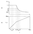
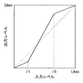
従来、例えば画像の階調特性の変換のために、入力画像の各画素に対し、そのレベルを図18の実線で示すような入出力関係を持つ関数(以下、「レベル変換関数」と記す。)で変換する方法(以下、「レベル変換」と記す。)がある。図18において、横軸は入力画像の画素レベル(入力レベル)lを、縦軸はレベル変換処理による出力画像の画素レベル(出力レベル)T(l)を表す。Lmaxは、入出力画像の各画素が取り得る最大レベルを表す。レベル変換後の画像のコントラストは、レベル変換関数の傾きが大きいほど増加することになる。図18の例では、入力レベルlbを境にして高レベル側と入力レベルlsを境にして低レベル側とにおけるレベル変換関数を示す直線の傾きが、中間レベル(入力レベルls〜lb)の傾きに比べて小さくなっている。従って、図18に示した関数を用いたレベル変換では、高レベルおよび低レベルにおけるコントラストを犠牲にすることで、中間レベルのコントラストを増加させていることになる。
【0003】
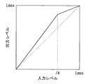
レベル変換関数は、図18に示したものに限らず、例えば図19の実線で示したものを用いることもできる。図19に示したレベル変換関数は、入力レベルlkを境にして、高レベル側における直線の傾きが、低レベル、中間レベルでの傾きに比べて小さくなっている。従って、図19に示した関数を用いたレベル変換では、高レベルでのコントラストを犠牲にすることで、低レベル、中間レベルでのコントラストを増加させることができる。また、以下の(1)式のガンマ関数や(2)式のLOG関数等、図18および図19に示した関数に比べて、より連続的なレベル変換関数が用いられることもある。なお、(1)式におけるgは関数の傾きを調整するパラメータである。
【0004】
【数1】

【数2】
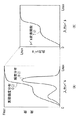
また、さらに別の従来例としては、入力画像の画素レベルの頻度分布に応じて、レベル変換関数を適応的に変化させる方法があり、その代表例としてはヒストグラムイコライゼーションと呼ばれる方法が挙げられる。図20(A),(B)に、このヒストグラムイコライゼーションの原理を示す。図20(A)において、横軸は入力画像の画素レベル(入力レベル)lを、縦軸は度数(頻度または累積頻度)を表す。Fmaxは、累積頻度の最大値であり、頻度を算出するために用いる画素の総数である。この方法では、図20(A)に示したように、はじめに入力画像の画素レベルlに関する頻度分布H(l)が生成され、次に以下の(3)式を用いて累積頻度分布C(l)が生成される。
【0007】
【数3】
この累積頻度分布C(l)の縦軸を、以下の(4)式を用いて出力画像が取り得るレベル範囲に正規化することにより、レベル変換関数T(l)が生成される(図20(B))。この関数T(l)を用いることにより、出現頻度の高いレベルによって構成される領域(面積が大きい領域)のコントラストを増加させることが可能となる。
【0009】
【数4】
入力された画像を、よりダイナミックレンジの小さい、すなわち画素レベルを表現するビット数が少ない環境で利用する場合(ビット数の少ない伝送路で伝送する場合や、表示装置に表示する場合、あるいは記憶装置に保存する場合など)には、ダイナミックレンジの圧縮を行う必要がある。従来は、このような目的でのダイナミックレンジの圧縮処理にも、上述した方法と同様のレベル変換が用いられている。ただし、この場合には、レベル変換関数の出力画像の最大レベルが、入力画像のそれよりも小さい値となる。
【0011】
一方、文献「Z. Rahman, et, alt.:"A Multiscale retinex for color rendition and dynamic range compression in Applications of Digital image Processing", XIX Proc. SPIE 2847 (1996)」では、空間的に緩やかに変化する照明光の成分をローパスフィルタによって抽出し、これを圧縮することで全体的なダイナミックレンジを圧縮する方法が提案されている(以下、この方法を「Multiscale retinex法」と記す。)。照明成分の抽出には帯域の狭い線形ローパスフィルタが用いられている。この方法では、以下の(5)式に示すように、入力画素の値I(x,y)、およびローパスフィルタ出力LPF(I(x,y))の対数値を取り、前者から後者を差し引くことによりダイナミックレンジの圧縮が行われる。
【0012】
【数5】
【発明が解決しようとする課題】
ところで、上述した従来のレベル変換方法では、不自然な画像が生成されるのを回避するため、単調増加性を有するレベル変換関数を用いている。このため、いずれかのレベル範囲のコントラスト(レベル変換関数の傾き)を増加させた場合、他のレベル範囲では逆にコントラストが低下してしまうといった問題がある。
【0014】
また、Multiscale retinex法では、単調増加性を犠牲にすることで、よりコントラストの高い画像を再現することを可能としているが、照明条件が急激に切り替わる場合、線形フィルタではその変化を抽出することができず、主観的に好ましくないノイズが発生してしまうという問題がある。
【0015】
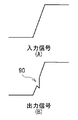
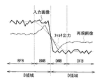
例えば、図21に示すように、照明条件の異なる2つの領域が隣接している画像(図中、実線)に対して線形ローパスフィルタを施すと、図中、細い破線で示したように境界のぼけた信号がフィルタ出力として得られる。これを照明成分と見なした場合、照明境界の左側の領域(B領域)において、境界付近(BNB領域)は、境界より離れた部分(BFB領域)よりも照明レベルが低いことになる。上述の(5)式は入力信号を照明成分で割り算することと等価であり、照明成分が大きいほど大きく圧縮されることを意味するため、結果として再現画像(図中、太い破線)のBNB領域にはオーバーシュートが発生する。逆に、照明境界の右側の領域(D領域)において、境界付近(DNB領域)は、境界より離れた部分(DFB)に比べて照明レベルが高いと見なされてアンダーシュートが発生する。Multiscale retinex法ではこの問題を回避するためにスケールの異なる複数の線形ローパスフィルタを用い、それぞれのローパスフィルタによって得られる結果を線形荷重によって合成する方法を用いているが、各スケールに対する重みは固定されており、上記の問題を十分に抑制できていない。
【0016】
そこで、照明成分の抽出に線形ローパスフィルタではなく、例えばイプシロンフィルタなどの非線形フィルタを用いることが考えられる。イプシロンフィルタは、線形フィルタに比べエッジを保存する能力にすぐれ、異なる照明光が存在する画像においても照明成分をより有効に抽出することができる。しかしながら、ノイズ除去などを目的に一般的に用いられているしきい値固定のイプシロンフィルタでは、その出力にエッジ近傍において不連続な波形が形成されるため、これをダイナミックレンジの圧縮用に用いた場合、圧縮後の再現画像に原画像にはない不自然な画像パターンが発生する可能性がある。
【0017】
本発明はかかる問題点に鑑みてなされたもので、その目的は、イプシロンフィルタを用いて、複数の異なる照明が存在する場合にも、それらの境界を適切に抽出することを可能とし、不自然な画像パターンの発生を抑えて、主観的に好ましいダイナミックレンジの圧縮を実現できる画像処理方法および装置を提供することにある。
【0018】
【課題を解決するための手段】
本発明による画像処理方法は、入力画像上の各位置ごとにエッジ強度を算出するエッジ強度算出過程と、算出されたエッジ強度に基づいて、イプシロンフィルタのしきい値を制御するしきい値制御過程と、しきい値制御過程において制御されたしきい値を用いて、入力画像にイプシロンフィルタによるフィルタ処理を施すフィルタリング過程と、フィルタリング過程の出力値に応じて、画素値を変換するための係数を算出し、その算出した係数により、各画素ごとに画素値の変換を行う画素値変換過程とを含むものである。
【0019】
本発明による画像処理装置は、入力画像上の各位置ごとにエッジ強度を算出するエッジ強度算出手段と、設定されたしきい値を用いて、入力画像にフィルタ処理を施すイプシロンフィルタと、エッジ強度算出手段によって算出されたエッジ強度に基づいて、イプシロンフィルタで用いられるしきい値を制御するしきい値制御手段と、イプシロンフィルタからの出力値に応じて、画素値を変換するための係数を算出し、その算出した係数により、各画素ごとに画素値の変換を行う画素値変換手段とを備えたものである。
【0020】
本発明による画像処理方法および装置では、入力画像上の各位置ごとにエッジ強度が算出され、その算出されたエッジ強度に基づいて、イプシロンフィルタで用いられるしきい値が制御される。そして、イプシロンフィルタからの出力値に応じて、画素値を変換するための係数が算出され、その算出された係数により、各画素ごとに画素値の変換が行われる。これにより、複数の異なる照明が存在する場合にも、イプシロンフィルタによるフィルタ処理において、それらの境界の抽出を適切に行うことが可能とされる。
【0022】
また、本発明による画像処理方法および装置では、大きさの異なる2つのしきい値を算出して、しきい値の制御を行う。このとき、イプシロンフィルタでは、近傍画素の値が注目画素に比べて大きい場合と小さい場合とで異なるしきい値を用いてフィルタ処理を行う。これによって、フィルタ処理において、画素値の変化における照明レベルの影響が軽減され、より適切に照明成分の抽出がなされる。
【0023】
【発明の実施の形態】
以下、本発明の実施の形態について図面を参照して詳細に説明する。
【0024】
[第1の実施の形態]
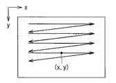
まず、本実施の形態に係る画像処理装置において処理される入力画像信号につて説明する。本画像処理装置において処理される入力画像信号は、2次元ディジタル画像を図2に示すように水平方向、垂直方向の順に走査して得られた時系列な画素値の信号である。本実施の形態では、2次元画像上の任意の位置(x,y)に対応する画素値をI(x,y)と表し、これを入力画像信号として処理する。
【0025】
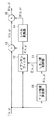
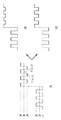
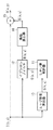
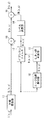
次に、本実施の形態に係る画像処理装置の構成について説明する。本画像処理装置は、図1に示したように、エッジ強度算出器10と、しきい値制御器11と、イプシロンフィルタ12と、除算器13と、レベル変換器14と、乗算器15とを備えている。
【0026】
エッジ強度算出器10は、入力画像の各位置において画素値I(x,y)のエッジ強度G(x,y)を算出する機能を有している。エッジ強度G(x,y)としては、例えば以下の(6)式で与えられるようなI(x,y)の1次微分値を用いることができる。
【0027】
【数6】
あるいは、ノイズの影響を抑えるために平滑化効果を持つ以下の(7)式による値をエッジ強度G(x,y)として用いることも可能である。
【0029】
【数7】
ここで、(6),(7)式において、dは微分を算出するための微小距離を示す定数である。エッジ強度算出器10において算出されたエッジ強度G(x,y)は、しきい値制御器11に送られる。
【0031】
しきい値制御器11は、エッジ強度算出器10によって算出されたエッジ強度G(x,y)に基づき、後述のイプシロンフィルタ12で用いるしきい値E(x,y)の大きさを画素ごとに決定する機能を有している。しきい値制御器11の機能により、しきい値E(x,y)は、例えば以下の(8)式を用いることにより、エッジ強度G(x,y)が大きいほど小さな値となるように制御される。
【0032】
【数8】
(8)式において、Gmin,Gmax,Emin,Emaxは、エッジ強度G(x,y)をしきい値E(x,y)に変換するための定数であり、それぞれエッジ強度の最小値、最大値、しきい値E(x,y)の最小値、最大値を表している。しきい値制御器11において決定されたしきい値E(x,y)は、イプシロンフィルタ12に送られる。
【0034】
イプシロンフィルタ12は、図4に示したように、例えば、差分器20と、絶対値算出器21と、比較器22と、線形ローパスフィルタ(図ではLPFと記す。)23とを有して構成されている。このイプシロンフィルタ12は、2次元のフィルタであり、しきい値制御器11によって決定されたしきい値E(x,y)を用いて、入力画像に非線形なフィルタ処理を施す機能を有している。イプシロンフィルタ12の出力R(x,y)は、照明成分として除算器13およびレベル変換器14に送られる。
【0035】
除算器13は、入力画像からイプシロンフィルタ12で算出された照明成分を除去するために、以下の(9)式に示すように、入力画像の各画素値I(x,y)を照明成分R(x,y)で割り算するようになっている。割り算した結果得られる非照明成分S(x,y)は、乗算器15に送られる。
【0036】
【数9】
レベル変換器14は、イプシロンフィルタ12で算出された照明成分R(x,y)を、以下の(10)式に示すように、レベル変換関数T(l)によってレベル変換することによって圧縮し、補正照明成分CR(x,y)を算出する機能を有している。
【0038】
【数10】
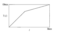
レベル変換器14で用いるレベル変換関数T(l)としては、例えば図3に示すような関数を用いることができる。なお、図3において、Rmax,CRmaxは、それぞれ入力レベルおよび出力レベルの最大値を表している。
【0040】
乗算器15は、以下の(11)式に示すように、非照明成分S(x,y)に補正照明成分CR(x,y)を積算することで画像信号を復元するようになっている。復元された結果を示す画像信号O(x,y)は、図示しない伝送路、記憶装置、または表示装置などに出力される。
【0041】
【数11】
なお、本実施の形態において、除算器13、レベル変換器14および乗算器15が、本発明における「画素値変換手段」の一具体例に対応する。
【0043】
次に、以上のように構成された画像処理装置の作用、動作を説明する。なお、以下の説明は、本実施の形態に係る画像処理方法の説明を兼ねている。
【0044】
本画像処理装置において、入力画像を示す信号は、エッジ強度算出器10、イプシロンフィルタ12および乗算器13に入力される。まず、エッジ強度算出器10では、入力画像の各位置ごとにエッジの大きさ、すなわちエッジ強度G(x,y)を算出する。このとき、エッジ強度算出器10は、例えば上述の(6)式または(7)式を用いることにより、注目画素の近傍領域内の画素値の1次微分値が大きいほど大きな値となるようにして、エッジ強度G(x,y)を算出する。エッジ強度算出器10は、算出したエッジ強度G(x,y)をしきい値制御器11に出力する。
【0045】
しきい値制御器11では、エッジ強度G(x,y)に基づいて、イプシロンフィルタ12のしきい値Eを制御する。より詳しくは、しきい値制御器11は、例えば上述の(8)式を用いて、しきい値E(x,y)の大きさを画素ごとに決定し、エッジ強度G(x,y)が大きいほどしきい値E(x,y)が小さくなるように制御する。しきい値制御器11は、決定されたしきい値E(x,y)をイプシロンフィルタ12に出力する。
【0046】
イプシロンフィルタ12では、しきい値制御器11によって決定されたしきい値E(x,y)を用いて、入力画像にフィルタ処理を施す。
【0047】
イプシロンフィルタ12でのフィルタ処理は、より詳しくは、例えば図4に示した構成により、以下のように行われる。イプシロンフィルタ12において、差分器20には、図4に示したように、現在の注目画素の値I(x,y)を示す信号とその近傍領域NB内の画素の値I(x+dx,y+dy)を示す信号とが入力される。差分器20では、注目画素の値I(x,y)とその近傍領域NB内の画素の値I(x+dx,y+dy)との差分を算出する。差分器20では、近傍領域NB内のすべての画素に対して順次この差分値を計算し、各近傍画素に対応づけて、その値D(dx,dy)を絶対値算出器21に出力する。
【0048】
絶対値算出器21では、差分器20より送られてくる各差分値D(dx,dy)の絶対値AD(dx,dy)を算出する。絶対値算出器21では、算出した絶対値AD(dx,dy)を比較器22に出力する。
【0049】
比較器22には、絶対値算出器21で算出された絶対値AD(dx,dy)が入力されると共に、注目画素の値I(x,y)を示す信号およびその近傍領域NB内の画素の値I(x+dx,y+dy)を示す信号、ならびに、しきい値制御器11で決定されたしきい値E(x,y)が入力される。比較器22では、以下の(12)式に示すように、絶対値AD(dx,dy)としきい値E(x,y)とを比較し、その結果に応じて、注目画素の値I(x,y)または近傍画素の値I(x+dx,y+dy)のいずれか一方を選択し、それを値J(dx,dy)として線形ローパスフィルタ23に出力する。
【0050】
【数12】
線形ローパスフィルタ23では、近傍領域NB内のすべての画素に対応する値J(dx,dy)が比較器22によって算出された時点で、以下の(13)式による加重平均値R(x,y)を算出する。
【0052】
【数13】
ここで、NBはフィルタリング処理における近傍領域を定義する相対的な座標の集合である。また、a(dx,dy)は各画素値に対する重み係数であり、この線形ローパスフィルタ23としては、例えば以下の(14)式に示すような平均値フィルタなどを用いることができる。
【0054】
【数14】
(14)式において、Nは近傍領域内NBの画素の数を表している。なお、イプシロンフィルタ12の目的は、画像中の細かい構造を除去し、まとまった領域を抽出することであり、その近傍領域は大きい方が望ましい。
【0056】
以上のようにしてイプシロンフィルタ12で得られた値R(x,y)は、近似的に画像に含まれる照明成分を表しているものと考えられる。イプシロンフィルタ12は、値R(x,y)を照明成分として除算器13およびレベル変換器14に出力する。
【0057】
除算器13では、上述の(9)式に示したように、入力画像の各画素値I(x,y)を照明成分R(x,y)で除算することにより、入力画像からイプシロンフィルタ12で算出された照明成分を除去し、その結果得られる非照明成分S(x,y)を乗算器15に出力する。
【0058】
一方、レベル変換器14では、イプシロンフィルタ12で算出された照明成分R(x,y)を、例えば図3に示すようなレベル変換関数T(l)によってレベル変換することによって圧縮し、補正照明成分CR(x,y)を算出する。レベル変換器14は、算出した補正照明成分CR(x,y)を乗算器15に出力する。
【0059】
乗算器15では、除算器13からの出力である非照明成分S(x,y)にレベル変換器14からの出力である補正照明成分CR(x,y)を積算することで画像信号を復元する。ここで、以上の除算器13、レベル変換器14および乗算器15での全体の演算について考察すると、非照明成分S(x,y)に補正照明成分CR(x,y)を積算することは、後述する(16)式に示すように、イプシロンフィルタ12からの出力値R(x,y)に応じて画素値を変換するための係数F(R(x,y))を算出し、それを対応する入力画素値I(x,y)に積算することで、各画素ごとに画素値の変換を行ってダイナミックレンジの圧縮を行っていることに相当する。
【0060】
以上のようにして乗算器15から出力される画像信号O(x,y)は、入力画像よりも相対的にダイナミックレンジの狭い画像装置、すなわち画素レベルを表現するビット数が少ない環境(ビット数の少ない伝送路で伝送する場合や、表示装置に表示する場合、あるいは記憶装置に保存する場合など)において利用される。
【0061】
次に、図5および図6を参照して、本実施の形態におけるイプシロンフィルタ12を用いてダイナミックレンジの圧縮を行った場合の、従来法(単調増加性を有するレベル変換関数を用いて圧縮を行う場合)に対する有効性について説明する。
【0062】
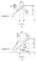
図5(A)は、入力画像の画素値I(x,y)、および本実施の形態におけるイプシロンフィルタ12からの出力R(x,y)を1次元信号として表した図である。図5(B)は、図5(A)に示した入力画像に対して従来のレベル変換法によるダイナミックレンジの圧縮を行った結果(再現画像)を示し、図5(C)は本実施の形態におけるダイナミックレンジの圧縮を行った結果を示す。
【0063】
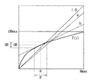
また、図6(A),(B)には、各領域の画素レベルとレベル変換関数T(l)、および係数算出関数F(l)との関係を示す。ここで、係数算出関数F(l)とは、レベル変換関数T(l)を用いて以下の(15)式のように定義される。
【0064】
【数15】
この係数算出関数F(l)を用い、上述の(9)式および(10)式を考慮することで、出力画像O(x,y)を与える(11)式は、以下の(16)式のように書き換えることが可能となる。
【0066】
【数16】
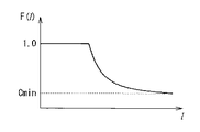
この(16)式は、照明成分R(x,y)の圧縮によるダイナミックレンジの圧縮が、画素ごとに算出される係数F(R(x,y))を、対応する入力画素値I(x,y)に積算することで実現できることを示している。このとき、係数算出関数F(l)は、イプシロンフィルタ12の出力値を各画素に施すゲイン係数に変換する機能を持つ。なお、図6(B)における係数算出関数F(l)の値の最小値Cminは、次の(17)式で与えられることになる。
【0068】
【数17】
図5(B)からも分かるように、従来法は低レベル領域(図5(A)に示すレベルl1とレベルl3とで構成されている領域)でのコントラストを保存することができるが、高レベル領域(レベルl4とレベルl6とで構成されている領域)においてはコントラストの低下を招いている。これは、変曲点lk以上の高いレベルに対するレベル変換関数T(l)の傾きの影響を直接的に受けた結果である。従来法においてコントラストを向上させるためにはレベル変換関数T(l)の傾きを大きくする必要がある。
【0070】
これに対し、本実施の形態(図5(C))では、高レベル領域および低レベル領域のそれぞれには、係数算出関数F(l)によって与えられる単一の補正係数が施されるため、各領域内のコントラストはこの補正係数の大きさに依存することになる。本実施の形態では、低レベル領域に対してはその平均レベルl2によって決まる補正係数が一様に施されるが、その値は、レベルl1およびレベルl3に対するものと同じ1.0であり、従来法と同程度のコントラストが得られる。また、高レベル領域に対しては、その平均値l5で決まる一定の補正係数c5が施されるため、レベルl4の部分とレベルl6の部分の間のコントラストは、このゲインで確保されることになる。
【0071】
実際、図6(A)に示すような、傾きの異なる2本の直線からなるレベル変換関数T(l)を用い、その変曲点レベルlk以上に対応する直線が以下の(18)式で表される場合には、従来法における高レベル領域のコントラストはその直線の傾きaに依存し、「a(l6−l4)/l5」で与えられる。ただし、ここではコントラストを「(最大レベル最小レベル)/平均レベル」で定義している。
【0072】
【数18】
一方、本実施の形態において高レベル領域に適用される補正係数c5は、以下の(19)式で与えられる。
【0074】
【数19】
従って、本実施の形態では、この領域のコントラストは、c5(l6−l4)/l5={a(l6−l4)/l5}+{b/(l5*l5)}となるが、ダイナミックレンジの圧縮におけるレベル変換関数T(l)の高レベルにおける傾きは通常1.0より小さいため、切片bは常に正の値を取る。このことは、従来法に比べて、イプシロンフィルタ12を用いた本実施の形態による方法がより高いコントラストを実現できることを示している。
【0076】
このように、本実施の形態においては、イプシロンフィルタ12によって抽出された領域内のコントラストが、係数算出関数F(l)によって与えられる補正係数の値そのものによって決まり、レベル変換関数T(l)の傾きは領域間のコントラストに影響を及ぼすことになる。従って、本実施の形態によれば、領域間のコントラストを圧縮することにより、領域内のコントラストを保存することができ、主観的に好ましい出力画像を得ることができる。
【0077】
次に、線形ローパスフィルタを用いた従来法に対する本実施の形態の効果について説明する。ただしここでは、説明を簡単にするため画像を1次元信号として表す。従来法の問題点は既に[発明が解決しようとする課題]の項目において図21を用いて説明したとおりであるが、その問題点を解決するためには、照明条件の異なる領域の境界(照明境界)を保存したまま、同一照明下の領域内を平滑化する必要がある。ところで、経験上、照明強度の変化に起因する画素レベルの変化は、物体表面の反射率に起因する画素レベルの変化よりもはるかに大きく、その結果、照明境界では画素レベルの大きなエッジが発生することになる。
【0078】
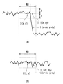
図7(A)に示すように、このようなエッジ周辺では、イプシロンフィルタ12の注目画素の近傍領域NB内にしきい値E(x,y)を超える大きな差分絶対値AD(dx,dy)を与える画素値I(x+dx,y+dy)が存在することになる。この画素値I(x+dx,y+dy)は、比較器22(図4)によって、図7(A)の太い破線(I'(dx,dy))で示すように、現在の注目画素の値(近傍領域NB中央の値)I(x,y)に置き換えられるため、(13)式による平滑化には大きく寄与せず、結果的にエッジの形状が保存されることになる。これに対し、照明境界以外の部分では、図7(B)に示すように、画素レベルの変化はそれほど大きなものにはならず、注目画素の近傍領域NB全体に渡り、差分絶対値AD(dx,dy)がしきい値E(x,y)よりも小さくなる。この場合、(12)式のJ(dx,dy)はすべて入力画素値I(x+dx,y+dy)と等しく、イプシロンフィルタは単純な線形ローパスフィルタと等価になり、近傍領域NB全体に渡る平滑化が行われる。
【0079】
このようにイプシロンフィルタ12は、線形フィルタに比べエッジを保存する能力にすぐれ、異なる照明光が存在する画像においても照明成分をより有効に抽出することができる。しかしながら、ノイズ除去などを目的に一般的に用いられているしきい値固定の従来のイプシロンフィルタでは、その出力にエッジ近傍において不連続な波形が形成されるため、これをダイナミックレンジの圧縮用に用いた場合、圧縮後の再現画像に原画像にはない不自然な画像パターンが発生する可能性がある。
【0080】
この問題点を説明するために、図8(A),(B)にモデル化したエッジとその周辺におけるしきい値固定の従来のイプシロンフィルタの出力を示す。ここではエッジ中央部から高レベル側のみを考え、レベルが急激に変化するエッジ部分は傾きaの直線で、それ以外のエッジ周辺部分は傾き0の平坦な直線で近似している。図8(A),(B)では、入力信号を細い実線81で、イプシロンフィルタの出力を太い実線82で、対応する線形ローパスフィルタの出力を太い破線83で示す。また、用いるイプシロンフィルタでの注目画素の近傍領域の大きさをN、そのしきい値をEとする。図8(A)は、a,N,Eの間に以下の(20)式の関係が成立している場合のイプシロンフィルタの出力である。
【0081】
【数20】
図8(A)において、横軸は空間的な位置座標を表し、右に行くほど座標値が大きくなるものとする。p0は、エッジの立下り点peからN/2だけ離れた位置を示している。この場合、イプシロンフィルタは線形ローパスフィルタと同等に振る舞う。しかしながら、照明光の変化による画像上のレベル変化は急峻に生じること(傾きaが大きい)、また上述したように効果的なダイナミックレンジの圧縮を行うためには大きなフィルタを用いる必要があること(Nが大きい)から、照明条件が変化する照明境界では通常(20)式の条件は成立しないと考えられる。
【0083】
一方、図8(B)には、(20)式が成立しない場合のイプシロンフィルタの出力を示す。図8(B)において、出力波形を右側から左側へと見ていくと、p0からp0−E/aまでは線形フィルタと同じ出力となり、その後peまでは一定の値を出力する。peからpe−E/aまでは2次曲線に従って下降するが、(20)式が成立しない条件のもとでは、この間に必ず入力信号を示す直線81と交差する。pe−E/aでは不連続的に入力信号と同じ値になり、その後入力信号をそのまま出力することになる。しきい値固定のイプシロンフィルタのこの振る舞いは、単純化したエッジモデルに対するものであるが、エッジ付近で複雑な波形を出力することは明らかである。特に、pe−E/aのあたりでは不連続に変化し、入力信号よりも大きな傾きを持った波形を出力する。
【0084】
出力画像O(x,y)が自然な再現画像となるためには、画像上の各位置における局所的な形状(空間的勾配の向き)が保存されていることが必要となる。すなわち、以下の(21)式に示すように、出力画像O(x,y)の微分値O'(x,y)の符号と入力画像I(x,y)の微分値I'(x,y)の符号とが一致しなければならない。
【0085】
【数21】
ここで、sign(x)はxの符号を表す。(21)式の条件が満たされない場合、入力画像と出力画像との間でレベル勾配の逆転が生じ、入力画像には存在しない画像パターンが出力画像に現れることになる。例えば図9(A)に示す入力画像が、図9(B)に示すように出力される。図9(B)の出力画像では、レベル勾配の逆転により、入力画像には存在しないパターン90が出現している。しかし、図8(B)に示すエッジ付近におけるイプシロンフィルタの不連続な振る舞いは、この(21)式の条件の成立を困難にする可能性があり、レベル勾配の逆転が生じるおそれがある。
【0087】
(21)式が成立するか否かは、イプシロンフィルタの振る舞いとその出力に施されるレベル変換関数T(l)に依存する。このことを明らかにするために、はじめに(11)式に(9)式を代入して入力画像I(x,y)と出力画像O(x,y)との関係(22)式を得る。
【0088】
【数22】
(22)式の右辺におけるCR(x,y)/R(x,y)は、先に述べた係数算出関数F(R(x,y))に相当する。(22)式の両辺を微分し、(21)式に代入することで、出力画像O(x,y)が満たすべき条件は以下の(23)式のように表されることになる。
【0090】
【数23】
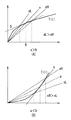
この条件に対するレベル変換関数T(l)の関与をさらに明確にするために、図10にイプシロンフィルタの出力に対するレベル変換関数T(l)の出力の関係を示す。横軸はイプシロンフィルタの出力(レベル変換関数T(l)への入力)、縦軸はレベル変換関数T(l)の出力を表している。いま、ある画素のイプシロンフィルタの出力をR、そのレベル変換後の値をCRとし、これらの比の値CR/Rをaとする。すなわち、aは原点と(R,CR)を通過する直線の傾きに相当する((24)式)。
【0092】
【数24】
またこの同じ画素におけるイプシロンフィルタの出力の空間微分値をR'とすると、これは図10の横軸上におけるRを中心とする微小範囲の大きさに相当するものと考えられる(ただしRは微分値を算出する画像上の方向に応じて適当な符号を有する)。従って、Rに対応するレベル変換関数T(l)のlに関する微係数をbとすると、レベル変換後の空間微分値は以下の(25)式によって近似できる。
【0094】
【数25】
(24)式および(25)式を(22)式に代入することで、イプシロンフィルタの出力に関する部分R'/Rと、レベル変換関数T(l)の性質に関する部分(1−b/a)とからなる以下の(26)式の条件を得ることができる。
【0096】
【数26】
なお、照明成分圧縮のためのレベル変換関数T(l)は、通常単調増加性を有するため、aおよびbは正の値となり、以下の(27)式が成立する。
【0098】
【数27】
なお、1−b/a≧0は、a≧bを意味するが、この場合には照明成分レベルRの近辺ではレベルが大きいほど大きな圧縮を施されることを意味している。なぜならば、レベルRの圧縮率はaであり、その近辺を一様に圧縮する場合にはレベルR近辺におけるレベル変換関数T(l)の傾きはaである必要があるが、実際の傾きはより小さいbであり、図11(A)に示すように高レベル側ほど大きく圧縮されることになる。逆に1−b/a、すなわちa<bの場合には、図11(B)に示すように低レベル側ほど大きく圧縮されることになる。なお、図11(A),(B)の縦軸および横軸は、図10と同様、それぞれイプシロンフィルタの出力(レベル変換関数T(l)への入力)およびレベル変換関数T(l)の出力を表す。
【0100】
エッジ付近以外の平坦部分では、イプシロンフィルタはローパスフィルタとして機能するため、一般的にその出力における空間的な変化の割合は、入力画像のそれよりも緩やかなものとなる。従って、これらの部分では以下の(28)式((28A),(28B))に示す2つの条件が成立していると仮定できる。
【0101】
【数28】
I'≧0の場合、(28)式よりR'≧0となるため、1−b/aが負であれば常に(26)式が成立することになる。また、0≦1−b/a≦1である場合には、(28)式から得られるI'/I≧R'/Rより、以下の(29)式のようになる。
【0103】
【数29】
同様に、I'<0の場合にも(26)式が成立することは容易に分かる。
【0105】
一方、図8(B)に示すとおり、エッジ中央部分においてはイプシロンフィルタは入力信号をそのまま出力することになるため、この部分では以下の(30)式が成立すると考えられるが、この場合にも(26)式が満足されることは明らかである。
【0106】
【数30】
本実施の形態においてイプシロンフィルタ12を除去し、R(x,y)=I(x,y)となるようにすれば、その結果はレベル変換のみによる従来法と等価となるが、これは画像全体に渡って(30)式の条件が成立している場合に相当し、従来法ではレベル勾配の逆転が発生しないことになる。
【0108】
これらの条件が満たされない部分では、(26)式が成立するか否かはイプシロンフィルタ12の出力とレベル変換関数T(l)の特性に依存する。レベル変換関数T(l)の特性は照明成分をどのように圧縮するかによって決められるべきものであるため、ここではイプシロンフィルタ12の出力がどのように(26)式の成立に影響を及ぼすかを4つの場合(1)〜(4)に分けて説明する。
【0109】
(1)I'≧0かつR'が1−b/aと同じ符号の場合;
右辺、左辺がともに正となるため、R'/Rの絶対値が大きいほど(26)式の成立が困難となる。
【0110】
(2)I'≧0かつR'が1−b/aと異なる符号の場合;
右辺が正、左辺が負となるため、常に(26)式が成立する。
【0111】
(3)I'<0かつR'が1−b/aと同じ符号の場合;
右辺が負、左辺が正となるため、常に(26)式が成立する。
【0112】
(4)I'<0かつR'が1−b/aと異なる符号の場合;
右辺、左辺がともに負となるため、R'/Rが大きいほど(26)式の成立が困難となる。
【0113】
上記(2)および(3)の条件のもとでは、近傍領域内において入力画像のレベルが高いほど少ない圧縮が施されることになるため、勾配の逆転が発生する可能性がない。従ってR'/Rがどのような値になっても常に(26)式が成立することになる。これに対して(1),(4)の条件では、R'/Rの絶対値が大きいほど(26)が満たされない可能性が高くなるが、少なくともその比が入力画像と同じであれば(26)式が成立することは上記に述べたとおりである。本実施の形態では、イプシロンフィルタ12のしきい値Eを可変とし、エッジ部分においては入力画像にできる限り近い信号を出力することで、すなわち、エッジ強度G(x,y)が大きいほど、イプシロンフィルタ12のしきい値Eが小さくなるようにしきい値を制御することで、勾配の逆転を最小限に抑制し、図9(B)に示したような不自然なパターン90が生じることのないよう、自然な画像を再現することを可能としている。
【0114】
なお、図3に示したレベル変換関数T(l)はあくまでも一例であり、目的に応じて任意のものを用いることができることはいうまでもない。例えば、(1)式や(2)式に示した関数を用いても良い。
【0115】
以上説明したように、本実施の形態によれば、入力画像上の各位置ごとにエッジ強度G(x,y)を算出すると共に、このエッジ強度G(x,y)に基づいて、イプシロンフィルタ12のしきい値E(x,y)を制御して入力画像にフィルタ処理を施し、また、そのイプシロンフィルタ12からの出力値R(x,y)に応じて算出される係数F(R(x,y))を、(16)式に示したように入力画素値I(x,y)に積算することによって、各画素ごとに画素値の変換を行ってダイナミックレンジの圧縮を行うようにしたので、複数の異なる照明が存在する場合にも、それらの境界を適切に抽出することを可能とし、不自然な画像パターンの発生を抑えて、主観的に好ましいダイナミックレンジの圧縮を実現できる。すなわち、イプシロンフィルタ12を用いて、入力画像から照明成分を抽出し、その照明成分を圧縮することにより、局所的なコントラストを保存したまま全体的なダイナミックレンジを削減し、主観的に好ましい再現画像を得ることができる。このとき、エッジ強度G(x,y)に基づいて、イプシロンフィルタ12のしきい値Eを画素値I(x,y)の局所的な勾配に応じて適応的に変化させるようにしたので、線形ローパスフィルタを用いた場合やしきい値固定のイプシロンフィルタを用いた場合よりも、より正確に照明境界を抽出することができる。
【0116】
[第2の実施の形態]
次に、本発明の第2の実施の形態について説明する。なお、以下の説明では、上記第1の実施の形態における構成要素と実質的に同一の機能を有する部分には同一の符号を付し、適宜説明を省略する。
【0117】
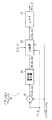
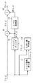
図12は、本発明の第2の実施の形態に係る画像処理装置の構成を示している。本実施の形態に係る画像処理装置の全体的な機能は、上記第1の実施の形態と同様であるが、本実施の形態では、除算器13およびレベル変換器14(図1)の代わりに、これらの機能をあわせ持った係数算出器16が設置されている点が、上記第1の実施の形態とは異なる。すなわち、本実施の形態は、上記第1の実施の形態で示した(16)式に基づいてダイナミックレンジの圧縮を行うものである。
【0118】
本実施の形態における係数算出器16では、イプシロンフィルタ12の出力R(x,y)に対して、図13に示すような係数算出関数F(l)を施して係数C(x,y)を算出する。係数算出関数F(l)は、上記第1の実施の形態で述べたように、レベル変換関数T(l)を用いて(15)式によって得られる。係数算出器16によって算出された係数C(x,y)は、乗算器15に送られる。
【0119】
本実施の形態における乗算器15には、入力画像を示す信号が直接入力されると共に、算出器16によって算出された係数C(x,y)が入力される。乗算器15では、入力画像の各画素値I(x,y)に対して対応する係数C(x,y)を積算することで画像信号を復元し、上記第1の実施の形態と同様、その結果の画像信号O(x,y)を図示しない伝送路、記憶装置または表示装置などに出力する。
【0120】
本実施の形態においても、エッジ強度G(x,y)に基づいて、イプシロンフィルタ12のしきい値E(x,y)を制御して入力画像にフィルタ処理を施し、また、そのイプシロンフィルタ12からの出力値R(x,y)に応じて算出される係数F(R(x,y))を、入力画素値I(x,y)に積算することによって、各画素ごとに画素値の変換を行ってダイナミックレンジの圧縮を行うようにしているので、上記第1の実施の形態と同様の効果を得ることができる。
【0121】
[第3の実施の形態]
次に、本発明の第3の実施の形態について説明する。なお、以下の説明では、上記第1の実施の形態または上記第2の実施の形態における構成要素と実質的に同一の機能を有する部分には同一の符号を付し、適宜説明を省略する。
【0122】
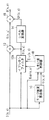
図14は、本発明の第3の実施の形態に係る画像処理装置の構成を示している。本実施の形態に係る画像処理装置の構成は、上記第1の実施の形態(図1)とほぼ同じであるが、しきい値制御器11に、エッジ強度算出器10からの出力であるエッジ強度G(x,y)のほかに、さらに、入力画像の画素値I(x,y)が直接入力されている点が異なる。
【0123】
本実施の形態におけるしきい値制御器11Aでは、後段のイプシロンフィルタ12で用いるしきい値E(x,y)を、エッジ強度G(x,y)のみではなく、入力画像の画素レベルによっても制御する。より具体的には、しきい値制御器11Aでは、入力画像の画素値I(x,y)が大きいほどしきい値E(x,y)が大きくなると共に、エッジ強度G(x,y)が大きいほどしきい値E(x,y)が小さくなるようにしきい値E(x,y)を制御する。
【0124】
このようなしきい値制御は、以下のようにして実現できる。例えば、まず、あらかじめ設定された正の係数r(r≦1.0)を用いて、以下の(31)式によって、入力画像の画素値I(x,y)が大きいほどその値が大きくなるような、仮のしきい値Etmp(x,y)を設定する。
【0125】
【数31】
その後、このしきい値Etmp(x,y)をエッジ強度G(x,y)により修正して実際に用いるしきい値E(x,y)を決定する。例えば、(8)式における正規化のための定数Emin,Emaxをそれぞれ0.0,1.0として、(8)式によってエッジ強度に応じた係数G(x,y)を算出するようにする。これを以下の(32)式のように、仮のしきい値Etmp(x,y)に積算して最終的なしきい値E(x,y)を求める。これにより、入力画像の画素値I(x,y)が大きいほどその値が大きくなると共に、エッジ強度G(x,y)が大きいほどその値が小さくなるよう、しきい値E(x,y)が制御される。
【0127】
【数32】
イプシロンフィルタ12のしきい値E(x,y)は、入力画素の空間的変化が照明成分の変化によるものか、物体表面の反射率の変化によるものかを分離する役割を担うが、物体表面の反射率の変化が小さい場合でも照明レベル自体が大きいと画素値I(x,y)の変化は大きくなる。すなわち、照明レベルの大きな変化と強い照明下における小さな反射率の変化とをどのように区別するかが問題となる。本実施の形態では、画素レベルが大きいほどイプシロンフィルタ12のしきい値E(x,y)を大きく設定するようにしているが、これにより画素値I(x,y)の変化における照明レベルの影響を軽減でき、より適切に照明成分を抽出することが可能となる。
【0129】
以上説明したように、本実施の形態によれば、エッジ強度G(x,y)のみならず、入力画像の画素レベルを考慮して、イプシロンフィルタ12のしきい値E(x,y)の制御を行うようにしたので、イプシロンフィルタ12において、より適切に照明成分を抽出することが可能となる。
【0130】
[第4の実施の形態]
次に、本発明の第4の実施の形態について説明する。なお、以下の説明では、上記第1〜第3の実施の形態における構成要素と実質的に同一の機能を有する部分には同一の符号を付し、適宜説明を省略する。
【0131】
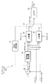
図15は、本発明の第4の実施の形態に係る画像処理装置の構成を示している。本実施の形態に係る画像処理装置の構成は、上記第3の実施の形態(図14)とほぼ同じであるが、特に、各画素ごとに2種類のしきい値Elo(x,y),Eup(x,y)を用いてイプシロンフィルタのしきい値制御を行うようにした点が上記第3の実施の形態とは異なる。
【0132】
本実施の形態におけるしきい値制御器11Bでは、各画素ごとに大きさの異なる2種類のしきい値Elo(x,y),Eup(x,y)を算出し、それらによってイプシロンフィルタ12Aのしきい値制御を行う。すなわち、しきい値制御器11Bでは、例えば、あらかじめ設定された大きさの異なる2つの係数rl,ru(0.0≦rl,ru≦1.0)を用いて、以下の(33)式((33A),(33B))のように、2種類の仮のしきい値Etmplo(x,y),Etmpup(x,y)を算出する。そして、それらを第1のしきい値Elo(x,y)および第2のEup(x,y)として、イプシロンフィルタ12Aに出力する。
【0133】
【数33】
本実施の形態におけるイプシロンフィルタ12Aでは、しきい値制御器11Bで算出された2つのしきい値Elo(x,y),Eup(x,y)によりしきい値処理を行う。イプシロンフィルタ12Aでの処理は、より詳しくは、例えば、図16に示した構成により、以下のようにして行われる。差分器20によって算出された差分値D(x,y)は、本実施の形態においては絶対値算出器21のほかに符号判定器24にも送られる。
【0135】
符号判定器24では、差分値D(x,y)の符号を判定し、その結果をスイッチ27に送る。
【0136】
第1の比較器25では、しきい値制御器11Bから送られてくる第1のしきい値Elo(x,y)を用いて、第1の実施の形態と同様、(12)式により信号の選択を行う。すなわち、絶対値算出器21で算出された値AD(dx,dy)としきい値Elo(x,y)とを比較し、その結果に応じて、注目画素の値I(x,y)または近傍画素の値I(x+dx,y+dy)のいずれか一方を選択し、それを値J(dx,dy)として出力する。
【0137】
第2の比較器26では、しきい値制御器11Bから送られてくる第2のしきい値Eup(x,y)を用いて、第1の実施の形態と同様(12)式により信号の選択を行う。すなわち、絶対値算出器21で算出された値AD(dx,dy)としきい値Eup(x,y)とを比較し、その結果に応じて、注目画素の値I(x,y)または近傍画素の値I(x+dx,y+dy)のいずれか一方を選択し、それを値J(dx,dy)として出力する。
【0138】
スイッチ27では、符号判定器24の判定結果をもとに、第1の比較器25または第2の比較器26の出力のいずれか一方を選択し、線形ローパスフィルタ23に送る。スイッチ27では、例えば、符号判定結果が正であることを示している場合には、第1の比較器25の出力を選択する。逆に、判定結果が負である場合には、第2の比較器26の出力を選択する。
【0139】
本実施の形態では、近傍画素の値I(x+dx,y+dy)が現在の注目画素の値(近傍領域NBの中央の値)I(x,y)よりも大きい場合にはしきい値Eup(x,y)が用いられ、小さい場合にはElo(x,y)が用いられる。すなわち、イプシロンフィルタ12Aにおいて、高レベル側と低レベル側とで異なるしきい値を設定することが可能となっている。特に、第2のしきい値Eup(x,y)が第1のしきい値Elo(x,y)よりも大きくなるようにすることで、第3の実施の形態と同様、画素値の変化に含まれる照明成分の影響を軽減することができ、より適切に照明成分を抽出することが可能となる。
【0140】
[第5の実施の形態]
次に、本発明の第5の実施の形態について説明する。なお、以下の説明では、上記第1〜第4の実施の形態における構成要素と実質的に同一の機能を有する部分には同一の符号を付し、適宜説明を省略する。
【0141】
図17は、本発明の第5の実施の形態に係る画像処理装置の構成を示している。本実施の形態に係る画像処理装置の構成は、上記第1の実施の形態(図1)と類似しているが、特に、はじめに入力画像の画素レベルに例えば対数変換などの非線形な変換を施すようにした点が異なる。
【0142】
すなわち、本実施の形態においては、回路の入力段に対数変換器17を設置し、はじめに入力画像の各画素値I(x,y)に対して(1)式に示した対数変換を施すようになっている。またこれに伴い、イプシロンフィルタ12で得られた照明成分R(x,y)を差し引くための除算器13が減算器18に、圧縮された照明成分CR(x,y)を非照明成分S(x,y)に積算するための乗算器15が加算器19に置き換えられている。これらは積算、除算が対数変換後には加算、減算となるという良く知られた事実に基づくものである。
【0143】
対数変換器17によって対数変換された後の入力画像の画素値IL(x,y)は、エッジ強度算出器10、イプシロンフィルタ12、および減算器18に送られる。エッジ強度算出器10およびイプシロンフィルタ12では、その画素値IL(x,y)に基づいて、上記第1の実施の形態と同様の処理を行う。一方、減算器18では、各画素値IL(x,y)から、イプシロンフィルタ12で得られた照明成分R(x,y)を減算することにより、入力画像から照明成分を除去し、その結果得られる非照明成分S(x,y)を加算器19に出力する。加算器19では、非照明成分S(x,y)に補正照明成分CR(x,y)を加算することで画像信号を復元し、上記第1の実施の形態と同様、その結果の画像信号O(x,y)を図示しない伝送路、記憶装置または表示装置などに出力する。
【0144】
本実施の形態で用いた対数変換は、それ自体がダイナミックレンジの圧縮効果を持ち、入力レベルが高いほど画素値I(x,y)が大きく圧縮される。これにより、上記第3および第4の実施の形態と実質的に同様、画素値の空間的な変化における照明レベルの影響が軽減されることになり、より適切に照明成分を抽出することが可能となる。
【0145】
なお、本実施の形態では、非線形な変換として対数変換を行う例について説明したが、対数変換以外の他の非線形な変換を行うようにしても良い。
【0146】
【発明の効果】
以上説明したように、本発明の画像処理方法または画像処理装置によれば、入力画像上の各位置ごとに算出されたエッジ強度に基づいて、イプシロンフィルタで用いられるしきい値を制御すると共に、そのしきい値の制御されたイプシロンフィルタからの出力値に応じて、画素値を変換するための係数を算出し、その算出された係数により、各画素ごとに画素値の変換を行うようにしたので、複数の異なる照明が存在する場合にも、それらの境界を適切に抽出することが可能となり、不自然な画像パターンの発生を抑えて、主観的に好ましいダイナミックレンジの圧縮を実現できる。
【図面の簡単な説明】
【図1】本発明の第1の実施の形態に係る画像処理装置の構成を示すブロック図である。
【図2】画像の走査方向を示す説明図である。
【図3】レベル変換関数の例について示す説明図である。
【図4】図1に示した画像処理装置におけるイプシロンフィルタの構成を示すブロック図である。
【図5】従来法による再現画像と図1に示した画像処理装置による再現画像との違いについて示す説明図である。
【図6】レベル変換関数と係数算出関数との関係について示す説明図である。
【図7】イプシロンフィルタの効果について示す説明図である。
【図8】しきい値固定のイプシロンフィルタのエッジ周辺における振る舞いについて示す説明図である。
【図9】しきい値固定のイプシロンフィルタにおいて生ずるレベル勾配の逆転現象について示す説明図である。
【図10】イプシロンフィルタの出力に用いられるレベル変換関数とその微分値との関係を示す説明図である。
【図11】レベル変換曲線における入力レベルと圧縮率の大小関数について示す説明図である。
【図12】本発明の第2の実施の形態に係る画像処理装置の構成を示すブロック図である。
【図13】図12に示した画像処理装置における係数算出器において用いられる係数算出関数の例について示す説明図である。
【図14】本発明の第3の実施の形態に係る画像処理装置の構成を示すブロック図である。
【図15】本発明の第4の実施の形態に係る画像処理装置の構成を示すブロック図である。
【図16】図15に示した画像処理装置におけるイプシロンフィルタの構成を示す説明図である。
【図17】本発明の第5の実施の形態に係る画像処理装置の構成を示すブロック図である。
【図18】従来用いられているレベル変換関数の例について示す説明図である。
【図19】従来用いられている他のレベル変換関数の例について示す説明図である。
【図20】ヒストグラムイコライゼーションの原理について示す説明図である。
【図21】 Multiscale retinex法の問題点について説明するための図である。
【符号の説明】
10…エッジ強度算出器、11…しきい値制御器、12,12A…イプシロンフィルタ、13…除算器、14…レベル変換器、15…乗算器、16…係数算出器、17…対数変換器、18,20…差分器、19…加算器、21…絶対値算出器、22、25,26…比較器、23…線形ローパスフィルタ(LPF)、24…符号判定器、27…スイッチ。[0001]
BACKGROUND OF THE INVENTION
The present invention can be suitably used for various image input / output devices such as a television, a video tape recorder, a still camera, a video camera and a printer. The present invention relates to an image processing method and apparatus for reproducing in a narrow image apparatus.
[0002]
[Prior art]
Conventionally, for example, for the conversion of the gradation characteristics of an image, a function having an input / output relationship as shown by a solid line in FIG. ) For conversion (hereinafter referred to as “level conversion”). In FIG. 18, the horizontal axis represents the pixel level (input level) 1 of the input image, and the vertical axis represents the pixel level (output level) T (l) of the output image obtained by level conversion processing. Lmax represents the maximum level that each pixel of the input / output image can take. The contrast of the image after level conversion increases as the slope of the level conversion function increases. In the example of FIG. 18, the slope of the straight line indicating the level conversion function between the high level with the input level lb as the boundary and the low level side with the input level ls as the boundary is the slope of the intermediate level (input levels ls to lb). It is smaller than Therefore, in the level conversion using the function shown in FIG. 18, the contrast at the intermediate level is increased by sacrificing the contrast at the high level and the low level.
[0003]
The level conversion function is not limited to the one shown in FIG. 18, and for example, the one shown by the solid line in FIG. In the level conversion function shown in FIG. 19, the slope of the straight line on the high level side is smaller than the slopes at the low level and the intermediate level with the input level lk as a boundary. Accordingly, in the level conversion using the function shown in FIG. 19, the contrast at the low level and the intermediate level can be increased by sacrificing the contrast at the high level. Further, a more continuous level conversion function may be used as compared with the functions shown in FIGS. 18 and 19 such as the following gamma function of equation (1) and LOG function of equation (2). Note that g in the equation (1) is a parameter for adjusting the slope of the function.
[0004]
[Expression 1]
[Expression 2]
As another conventional example, there is a method of adaptively changing the level conversion function in accordance with the frequency distribution of the pixel level of the input image. A typical example is a method called histogram equalization. FIGS. 20A and 20B show the principle of this histogram equalization. In FIG. 20A, the horizontal axis represents the pixel level (input level) 1 of the input image, and the vertical axis represents the frequency (frequency or cumulative frequency). Fmax is the maximum value of the cumulative frequency, and is the total number of pixels used for calculating the frequency. In this method, as shown in FIG. 20A, first, a frequency distribution H (l) relating to the
[0007]
[Equation 3]
A level conversion function T (l) is generated by normalizing the vertical axis of the cumulative frequency distribution C (l) to a level range that can be taken by the output image using the following equation (4) (FIG. 20). (B)). By using this function T (l), it is possible to increase the contrast of a region (region having a large area) constituted by a level having a high appearance frequency.
[0009]
[Expression 4]
When the input image is used in an environment with a smaller dynamic range, that is, with a small number of bits representing the pixel level (when transmitted through a transmission path with a small number of bits, when displayed on a display device, or a storage device) In the case of storing in (for example), it is necessary to compress the dynamic range. Conventionally, level conversion similar to the above-described method is also used for dynamic range compression processing for such a purpose. However, in this case, the maximum level of the output image of the level conversion function is a value smaller than that of the input image.
[0011]
On the other hand, in the document “Z. Rahman, et, alt .:“ A Multiscale retinex for color rendition and dynamic range compression in Applications of Digital image Processing ”, XIX Proc. SPIE 2847 (1996), it changes slowly and spatially. A method of compressing the entire dynamic range by extracting a component of illumination light using a low-pass filter and compressing the component is proposed (hereinafter, this method is referred to as “Multiscale retinex method”). A narrow-band linear low-pass filter is used to extract the illumination component. In this method, as shown in the following formula (5), logarithmic values of the input pixel value I (x, y) and the low-pass filter output LPF (I (x, y)) are taken and the latter is subtracted from the former. As a result, the dynamic range is compressed.
[0012]
[Equation 5]
[Problems to be solved by the invention]
By the way, in the conventional level conversion method described above, a level conversion function having a monotonically increasing property is used in order to avoid generation of an unnatural image. For this reason, when the contrast (gradient of the level conversion function) in any one of the level ranges is increased, there is a problem that the contrast is lowered in the other level ranges.
[0014]
In addition, the Multiscale retinex method can reproduce images with higher contrast by sacrificing monotonic increase, but if the lighting conditions change rapidly, the linear filter can extract the change. There is a problem that noise that cannot be subjectively generated occurs.
[0015]
For example, as shown in FIG. 21, when a linear low-pass filter is applied to an image (solid line in the figure) in which two regions having different illumination conditions are adjacent to each other, A blurred signal is obtained as the filter output. When this is regarded as an illumination component, in the left area (B area) of the illumination boundary, the vicinity of the boundary (BNB area) has a lower illumination level than the part far away from the boundary (BFB area). The above equation (5) is equivalent to dividing the input signal by the illumination component, and means that the larger the illumination component is, the larger the compression is. Therefore, as a result, the BNB region of the reproduced image (thick broken line in the figure) Overshoot occurs. Conversely, in the area on the right side of the illumination boundary (D area), the vicinity of the boundary (DNB area) is considered to have a higher illumination level than the portion (DFB) far from the boundary, and undershoot occurs. To avoid this problem, the Multiscale retinex method uses multiple linear low-pass filters with different scales, and uses a method of combining the results obtained by each low-pass filter with a linear load, but the weight for each scale is fixed. The above problems are not sufficiently suppressed.
[0016]
Therefore, it is conceivable to use a non-linear filter such as an epsilon filter instead of a linear low-pass filter for extraction of illumination components. The epsilon filter has an excellent ability to preserve edges compared to a linear filter, and can extract illumination components more effectively even in an image in which different illumination light exists. However, the fixed threshold epsilon filter, which is generally used for the purpose of noise removal, forms a discontinuous waveform in the vicinity of the edge at the output, so this was used for dynamic range compression. In this case, an unnatural image pattern that does not exist in the original image may occur in the reproduced image after compression.
[0017]
The present invention has been made in view of such problems, and an object of the present invention is to use an epsilon filter to appropriately extract the boundaries even when there are a plurality of different illuminations. It is an object of the present invention to provide an image processing method and apparatus capable of suppressing the occurrence of a complex image pattern and realizing a subjectively preferable dynamic range compression.
[0018]
[Means for Solving the Problems]
An image processing method according to the present invention includes an edge intensity calculation process for calculating edge intensity for each position on an input image, and a threshold control process for controlling a threshold value of an epsilon filter based on the calculated edge intensity. And a filtering process in which the input image is filtered by an epsilon filter using the threshold value controlled in the threshold control process, and a coefficient for converting the pixel value according to the output value of the filtering process. And a pixel value conversion process in which pixel values are converted for each pixel based on the calculated coefficients.
[0019]
An image processing apparatus according to the present invention includes an edge strength calculation unit that calculates edge strength for each position on an input image, an epsilon filter that performs filtering on the input image using a set threshold, and edge strength. Based on the edge intensity calculated by the calculation means, a threshold control means for controlling the threshold value used in the epsilon filter, and a coefficient for converting the pixel value according to the output value from the epsilon filter are calculated. The pixel value conversion means for converting the pixel value for each pixel by the calculated coefficient is provided.
[0020]
In the image processing method and apparatus according to the present invention, the edge strength is calculated for each position on the input image, and the threshold value used in the epsilon filter is controlled based on the calculated edge strength. Then, a coefficient for converting the pixel value is calculated according to the output value from the epsilon filter, and the pixel value is converted for each pixel by the calculated coefficient. As a result, even when there are a plurality of different illuminations, it is possible to appropriately extract the boundaries in the filter processing by the epsilon filter.
[0022]
Also, In the image processing method and apparatus according to the present invention, Calculating two thresholds with different sizes and controlling the threshold Yeah. At this time, the epsilon filter , Filter processing is performed using different threshold values depending on whether the value of the neighboring pixel is larger or smaller than the target pixel. This And In the filter processing, the influence of the illumination level in the change of the pixel value is reduced, and the illumination component is extracted more appropriately.
[0023]
DETAILED DESCRIPTION OF THE INVENTION
Hereinafter, embodiments of the present invention will be described in detail with reference to the drawings.
[0024]
[First Embodiment]
First, an input image signal processed in the image processing apparatus according to the present embodiment will be described. The input image signal processed in this image processing apparatus is a signal of time-series pixel values obtained by scanning a two-dimensional digital image in the order of the horizontal direction and the vertical direction as shown in FIG. In the present embodiment, a pixel value corresponding to an arbitrary position (x, y) on the two-dimensional image is represented as I (x, y), and this is processed as an input image signal.
[0025]
Next, the configuration of the image processing apparatus according to the present embodiment will be described. As shown in FIG. 1, the image processing apparatus includes an
[0026]
The
[0027]
[Formula 6]
Alternatively, a value according to the following equation (7) having a smoothing effect to suppress the influence of noise can be used as the edge strength G (x, y).
[0029]
[Expression 7]
Here, in the equations (6) and (7), d is a constant indicating a minute distance for calculating the differentiation. The edge strength G (x, y) calculated by the
[0031]
Based on the edge strength G (x, y) calculated by the
[0032]
[Equation 8]
In equation (8), Gmin, Gmax, Emin, and Emax are constants for converting the edge strength G (x, y) to the threshold value E (x, y), and the minimum value and the maximum value of the edge strength, respectively Value, the minimum value and the maximum value of the threshold value E (x, y). The threshold value E (x, y) determined by the
[0034]
As shown in FIG. 4, the
[0035]
In order to remove the illumination component calculated by the
[0036]
[Equation 9]
The
[0038]
[Expression 10]
As the level conversion function T (l) used in the
[0040]
The
[0041]
## EQU11 ##
In the present embodiment, the
[0043]
Next, the operation and operation of the image processing apparatus configured as described above will be described. The following description also serves as a description of the image processing method according to the present embodiment.
[0044]
In this image processing apparatus, a signal indicating an input image is input to the
[0045]
The
[0046]
The
[0047]
More specifically, the filtering process in the
[0048]
The
[0049]
The
[0050]
[Expression 12]
In the linear low-
[0052]
[Formula 13]
Here, NB is a set of relative coordinates that define a neighboring region in the filtering process. Further, a (dx, dy) is a weighting factor for each pixel value. As this linear low-
[0054]
[Expression 14]
In the equation (14), N represents the number of pixels in the near region NB. The purpose of the
[0056]
The value R (x, y) obtained by the
[0057]
The
[0058]
On the other hand, the
[0059]
In the
[0060]
As described above, the image signal O (x, y) output from the
[0061]
Next, referring to FIG. 5 and FIG. 6, when the dynamic range is compressed using the
[0062]
FIG. 5A is a diagram representing the pixel value I (x, y) of the input image and the output R (x, y) from the
[0063]
6A and 6B show the relationship between the pixel level of each region, the level conversion function T (l), and the coefficient calculation function F (l). Here, the coefficient calculation function F (l) is defined as the following equation (15) using the level conversion function T (l).
[0064]
[Expression 15]
Using this coefficient calculation function F (l) and considering the above-mentioned formulas (9) and (10), the formula (11) that gives the output image O (x, y) is the following formula (16): It can be rewritten as
[0066]
[Expression 16]
This equation (16) indicates that the compression of the dynamic range by the compression of the illumination component R (x, y) represents the coefficient F (R (x, y)) calculated for each pixel and the corresponding input pixel value I (x , Y) shows that it can be realized by integrating. At this time, the coefficient calculation function F (l) has a function of converting the output value of the
[0068]
[Expression 17]
As can be seen from FIG. 5B, the conventional method can preserve the contrast in the low level region (the region formed by the
[0070]
On the other hand, in the present embodiment (FIG. 5C), each of the high level region and the low level region is subjected to a single correction coefficient given by the coefficient calculation function F (l). The contrast in each region depends on the magnitude of this correction coefficient. In the present embodiment, the correction coefficient determined by the
[0071]
Actually, as shown in FIG. 6A, a level conversion function T (l) composed of two straight lines having different inclinations is used, and the change is made. Song When a straight line corresponding to the point level lk or higher is expressed by the following equation (18), the contrast of the high level region in the conventional method depends on the slope a of the straight line, and “a (16−14) / 15”. Is given. However, here, the contrast is defined as “(maximum level / minimum level) / average level”.
[0072]
[Formula 18]
On the other hand, the correction coefficient c5 applied to the high level region in the present embodiment is given by the following equation (19).
[0074]
[Equation 19]
Therefore, in this embodiment, the contrast of this region is c5 (l6-l4) / l5 = {a (l6-l4) / l5} + {b / (l5 * l5)}, but the dynamic range Since the slope at the high level of the level conversion function T (l) in compression is usually smaller than 1.0, the intercept b always takes a positive value. This indicates that the method according to the present embodiment using the
[0076]
Thus, in the present embodiment, the contrast in the region extracted by the
[0077]
Next, the effect of the present embodiment over the conventional method using a linear low-pass filter will be described. Here, however, the image is represented as a one-dimensional signal for the sake of simplicity. The problems of the conventional method have already been described with reference to FIG. 21 in the section [Problems to be solved by the invention]. In order to solve the problems, the boundary between the areas with different illumination conditions (illumination) It is necessary to smooth the area under the same illumination while preserving the boundary. By the way, from experience, the change in the pixel level due to the change in the illumination intensity is much larger than the change in the pixel level due to the reflectance of the object surface. As a result, an edge with a large pixel level is generated at the illumination boundary. It will be.
[0078]
As shown in FIG. 7A, around such an edge, a large absolute difference value AD (dx, dy) exceeding the threshold value E (x, y) is present in the vicinity region NB of the target pixel of the
[0079]
As described above, the
[0080]
In order to explain this problem, FIGS. 8A and 8B show the output of a conventional epsilon filter with a fixed threshold value at the edges modeled around the edges. Here, only the high level side from the edge central portion is considered, and the edge portion where the level changes abruptly is approximated by a straight line having a slope a, and the other peripheral portions of the edge are approximated by a flat straight line having a
[0081]
[Expression 20]
In FIG. 8A, the horizontal axis represents the spatial position coordinate, and the coordinate value increases toward the right. p0 indicates a position separated by N / 2 from the edge falling point pe. In this case, the epsilon filter behaves like a linear low-pass filter. However, the level change on the image due to the change of the illumination light occurs steeply (the inclination a is large), and it is necessary to use a large filter in order to perform effective dynamic range compression as described above ( (N is large), it is considered that the condition of the equation (20) is not normally satisfied at the illumination boundary where the illumination condition changes.
[0083]
On the other hand, FIG. 8B shows the output of the epsilon filter when the equation (20) is not satisfied. In FIG. 8B, when the output waveform is viewed from the right side to the left side, the output is the same as that of the linear filter from p0 to p0-E / a, and then a constant value is output until pe. From pe to pe-E / a, it descends according to a quadratic curve. However, under the condition that equation (20) does not hold, it always intersects with the straight line 81 indicating the input signal. At pe-E / a, it becomes discontinuously the same value as the input signal, and then the input signal is output as it is. This behavior of a fixed threshold epsilon filter is for a simplified edge model, but it is clear that it outputs a complex waveform near the edge. In particular, the waveform changes discontinuously around pe-E / a and outputs a waveform having a larger slope than the input signal.
[0084]
In order for the output image O (x, y) to be a natural reproduction image, it is necessary to store the local shape (direction of spatial gradient) at each position on the image. That is, as shown in the following equation (21), the sign of the differential value O ′ (x, y) of the output image O (x, y) and the differential value I ′ (x, y) of the input image I (x, y). The sign of y) must match.
[0085]
[Expression 21]
Here, sign (x) represents the sign of x. When the condition of the equation (21) is not satisfied, the level gradient is reversed between the input image and the output image, and an image pattern that does not exist in the input image appears in the output image. For example, the input image shown in FIG. 9A is output as shown in FIG. In the output image of FIG. 9B, a
[0087]
Whether or not the equation (21) is satisfied depends on the behavior of the epsilon filter and the level conversion function T (l) applied to the output. In order to clarify this, the relationship (22) between the input image I (x, y) and the output image O (x, y) is first obtained by substituting the equation (9) into the equation (11).
[0088]
[Expression 22]
CR (x, y) / R (x, y) on the right side of the equation (22) corresponds to the coefficient calculation function F (R (x, y)) described above. By differentiating both sides of the equation (22) and substituting it into the equation (21), the condition to be satisfied by the output image O (x, y) is expressed as the following equation (23).
[0090]
[Expression 23]
In order to further clarify the involvement of the level conversion function T (l) with respect to this condition, FIG. 10 shows the relationship of the output of the level conversion function T (l) with respect to the output of the epsilon filter. The horizontal axis represents the output of the epsilon filter (input to the level conversion function T (l)), and the vertical axis represents the output of the level conversion function T (l). Now, the output of the epsilon filter of a certain pixel is R, the value after level conversion is CR, and the ratio value CR / R is a. That is, a corresponds to the slope of the straight line passing through the origin and (R, CR) (Equation (24)).
[0092]
[Expression 24]
If the spatial differential value of the output of the epsilon filter in this same pixel is R ′, this is considered to correspond to the size of a minute range centered on R on the horizontal axis of FIG. It has an appropriate sign depending on the direction on the image from which the value is calculated). Accordingly, if the differential coefficient for l of the level conversion function T (l) corresponding to R is b, the spatial differential value after level conversion can be approximated by the following equation (25).
[0094]
[Expression 25]
By substituting the equations (24) and (25) into the equation (22), the portion R ′ / R related to the output of the epsilon filter and the portion related to the property of the level conversion function T (l) (1-b / a) The condition of the following formula (26) consisting of
[0096]
[Equation 26]
Note that the level conversion function T (l) for compressing the illumination component usually has a monotonic increase, so a and b are positive values, and the following equation (27) is established.
[0098]
[Expression 27]
Note that 1−b / a ≧ 0 means a ≧ b. In this case, in the vicinity of the illumination component level R, it means that the greater the level, the greater the compression. This is because the compression ratio of level R is a, and in the case where the vicinity thereof is uniformly compressed, the slope of the level conversion function T (l) in the vicinity of level R needs to be a, but the actual slope is It is smaller b, and as shown in FIG. 11A, the higher the level, the greater the compression. On the other hand, in the case of 1-b / a, that is, a <b, as shown in FIG. 11A and 11B, the vertical axis and the horizontal axis indicate the output of the epsilon filter (input to the level conversion function T (l)) and the level conversion function T (l), respectively, as in FIG. Represents the output.
[0100]
Since the epsilon filter functions as a low-pass filter in a flat portion other than the vicinity of the edge, the rate of spatial change in the output is generally slower than that of the input image. Therefore, in these portions, it can be assumed that the two conditions shown in the following formula (28) ((28A), (28B)) are satisfied.
[0101]
[Expression 28]
When I ′ ≧ 0, R ′ ≧ 0 from the equation (28). Therefore, if 1−b / a is negative, the equation (26) always holds. When 0 ≦ 1-b / a ≦ 1, I ′ / I ≧ R ′ / R obtained from the equation (28) gives the following equation (29).
[0103]
[Expression 29]
Similarly, it can be easily understood that the expression (26) is also established when I ′ <0.
[0105]
On the other hand, as shown in FIG. 8B, since the epsilon filter outputs the input signal as it is in the center portion of the edge, the following equation (30) is considered to be satisfied in this portion. It is clear that the expression (26) is satisfied.
[0106]
[30]
If the
[0108]
In a portion where these conditions are not satisfied, whether or not the equation (26) is satisfied depends on the output of the
[0109]
(1) When I ′ ≧ 0 and R ′ has the same sign as 1-b / a;
Since both the right side and the left side are positive, the larger the absolute value of R ′ / R, the more difficult it is to establish equation (26).
[0110]
(2) When I ′ ≧ 0 and R ′ is a code different from 1-b / a;
Since the right side is positive and the left side is negative, equation (26) always holds.
[0111]
(3) When I ′ <0 and R ′ has the same sign as 1-b / a;
Since the right side is negative and the left side is positive, equation (26) always holds.
[0112]
(4) I '< 0 And R ′ is a code different from 1-b / a;
Since both the right side and the left side are negative, the larger R ′ / R is, the more difficult it is to establish the expression (26).
[0113]
Under the conditions (2) and (3), the higher the level of the input image in the vicinity region, the smaller the compression is performed, and therefore there is no possibility that the gradient will be reversed. Therefore, equation (26) always holds regardless of the value of R ′ / R. On the other hand, under the conditions (1) and (4), the larger the absolute value of R ′ / R, the higher the possibility that (26) will not be satisfied, but at least if the ratio is the same as the input image ( As described above, the expression (26) is established. In the present embodiment, the threshold value E of the
[0114]
Note that the level conversion function T (l) shown in FIG. 3 is merely an example, and it goes without saying that an arbitrary one can be used according to the purpose. For example, you may use the function shown to (1) Formula and (2) Formula.
[0115]
As described above, according to the present embodiment, the edge strength G (x, y) is calculated for each position on the input image, and the epsilon filter is based on the edge strength G (x, y). The threshold value E (x, y) of 12 is controlled to filter the input image, and the coefficient F (R (R ()) calculated according to the output value R (x, y) from the epsilon filter 12 x, y)) is added to the input pixel value I (x, y) as shown in the equation (16), so that the pixel value is converted for each pixel to compress the dynamic range. Therefore, even when there are a plurality of different illuminations, it is possible to appropriately extract the boundaries between them, suppress the occurrence of an unnatural image pattern, and realize compression of a subjectively preferable dynamic range. That is, the
[0116]
[Second Embodiment]
Next, a second embodiment of the present invention will be described. In the following description, parts having substantially the same functions as the constituent elements in the first embodiment are denoted by the same reference numerals, and description thereof will be omitted as appropriate.
[0117]
FIG. 12 shows the configuration of an image processing apparatus according to the second embodiment of the present invention. The overall function of the image processing apparatus according to the present embodiment is the same as that of the first embodiment, but in this embodiment, instead of the
[0118]
In the
[0119]
The
[0120]
Also in the present embodiment, the threshold value E (x, y) of the
[0121]
[Third Embodiment]
Next, a third embodiment of the present invention will be described. In the following description, parts having substantially the same functions as the constituent elements in the first embodiment or the second embodiment are denoted by the same reference numerals, and description thereof will be omitted as appropriate.
[0122]
FIG. 14 shows the configuration of an image processing apparatus according to the third embodiment of the present invention. The configuration of the image processing apparatus according to the present embodiment is almost the same as that of the first embodiment (FIG. 1), but the
[0123]
In the threshold controller 11A in the present embodiment, the threshold E (x, y) used in the
[0124]
Such threshold control can be realized as follows. For example, first, by using a positive coefficient r (r ≦ 1.0) set in advance, the value increases as the pixel value I (x, y) of the input image increases according to the following equation (31). A temporary threshold value Etmp (x, y) is set.
[0125]
[31]
Thereafter, the threshold value Etmp (x, y) is corrected by the edge strength G (x, y) to determine the threshold value E (x, y) that is actually used. For example, the constants Emin and Emax for normalization in the equation (8) are set to 0.0 and 1.0, respectively, and the coefficient G (x, y) corresponding to the edge strength is calculated by the equation (8). . This is integrated to a temporary threshold value Etmp (x, y) as shown in the following equation (32) to obtain a final threshold value E (x, y). Thus, the threshold value E (x, y) is set such that the larger the pixel value I (x, y) of the input image is, the larger the value is, and the smaller the edge intensity G (x, y) is. ) Is controlled.
[0127]
[Expression 32]
The threshold value E (x, y) of the
[0129]
As described above, according to the present embodiment, the threshold value E (x, y) of the
[0130]
[Fourth Embodiment]
Next, a fourth embodiment of the present invention will be described. In the following description, parts having substantially the same functions as those in the first to third embodiments are denoted by the same reference numerals, and description thereof is omitted as appropriate.
[0131]
FIG. 15 shows the configuration of an image processing apparatus according to the fourth embodiment of the present invention. The configuration of the image processing apparatus according to the present embodiment is substantially the same as that of the third embodiment (FIG. 14). In particular, two types of threshold values Elo (x, y), The point that the threshold control of the epsilon filter is performed using Eup (x, y) is different from the third embodiment.
[0132]
In the
[0133]
[Expression 33]
In the
[0135]
The
[0136]
The
[0137]
The
[0138]
The
[0139]
In this embodiment, when the value I (x + dx, y + dy) of the neighboring pixel is larger than the current value of the pixel of interest (the center value of the neighboring region NB) I (x, y), the threshold value Eup (x , Y) is used, and Elo (x, y) is used when it is small. That is, in the
[0140]
[Fifth Embodiment]
Next, a fifth embodiment of the present invention will be described. In the following description, parts having substantially the same functions as those in the first to fourth embodiments are denoted by the same reference numerals, and description thereof is omitted as appropriate.
[0141]
FIG. 17 shows the configuration of an image processing apparatus according to the fifth embodiment of the present invention. The configuration of the image processing apparatus according to the present embodiment is similar to that of the first embodiment (FIG. 1). In particular, first, nonlinear conversion such as logarithmic conversion is performed on the pixel level of the input image. The difference is that.
[0142]
That is, in the present embodiment, the
[0143]
The pixel value IL (x, y) of the input image after logarithmic conversion by the
[0144]
The logarithmic transformation used in the present embodiment itself has a dynamic range compression effect, and the pixel value I (x, y) is more greatly compressed as the input level is higher. Thereby, substantially the same as in the third and fourth embodiments, the influence of the illumination level in the spatial change of the pixel value is reduced, and the illumination component can be extracted more appropriately. It becomes.
[0145]
In this embodiment, an example in which logarithmic transformation is performed as nonlinear transformation has been described. However, nonlinear transformation other than logarithmic transformation may be performed.
[0146]
【The invention's effect】
As explained above, Of the present invention Image processing method or Is a picture According to the image processing apparatus, the threshold value used in the epsilon filter is controlled based on the edge intensity calculated for each position on the input image, and the output from the epsilon filter whose threshold value is controlled. According to the value, a coefficient for converting the pixel value is calculated, and the pixel value is converted for each pixel by the calculated coefficient, so even when there are a plurality of different illuminations, It is possible to appropriately extract these boundaries, suppress the generation of an unnatural image pattern, and realize compression of a subjectively preferable dynamic range.
[Brief description of the drawings]
FIG. 1 is a block diagram showing a configuration of an image processing apparatus according to a first embodiment of the present invention.
FIG. 2 is an explanatory diagram illustrating an image scanning direction.
FIG. 3 is an explanatory diagram showing an example of a level conversion function.
4 is a block diagram showing a configuration of an epsilon filter in the image processing apparatus shown in FIG. 1. FIG.
FIG. 5 is an explanatory diagram showing a difference between a reproduced image by a conventional method and a reproduced image by the image processing apparatus shown in FIG. 1;
FIG. 6 is an explanatory diagram showing a relationship between a level conversion function and a coefficient calculation function.
FIG. 7 is an explanatory diagram showing effects of an epsilon filter.
FIG. 8 is an explanatory diagram showing a behavior around an edge of an epsilon filter having a fixed threshold value;
FIG. 9 is an explanatory diagram showing a level gradient inversion phenomenon that occurs in an epsilon filter with a fixed threshold value.
FIG. 10 is an explanatory diagram showing a relationship between a level conversion function used for the output of the epsilon filter and a differential value thereof.
FIG. 11 is an explanatory diagram showing a magnitude function of an input level and a compression rate in a level conversion curve.
FIG. 12 is a block diagram showing a configuration of an image processing apparatus according to a second embodiment of the present invention.
13 is an explanatory diagram showing an example of a coefficient calculation function used in a coefficient calculator in the image processing apparatus shown in FIG.
FIG. 14 is a block diagram showing a configuration of an image processing apparatus according to a third embodiment of the present invention.
FIG. 15 is a block diagram showing a configuration of an image processing apparatus according to a fourth embodiment of the present invention.
16 is an explanatory diagram showing a configuration of an epsilon filter in the image processing apparatus shown in FIG.
FIG. 17 is a block diagram showing a configuration of an image processing apparatus according to a fifth embodiment of the present invention.
FIG. 18 is an explanatory diagram showing an example of a level conversion function used conventionally.
FIG. 19 is an explanatory diagram showing an example of another level conversion function used conventionally.
FIG. 20 is an explanatory diagram showing the principle of histogram equalization.
FIG. 21 is a diagram for explaining problems of the Multiscale retinex method.
[Explanation of symbols]
DESCRIPTION OF
Claims (10)
入力画像上の各位置ごとにエッジ強度を算出するエッジ強度算出過程と、
算出された前記エッジ強度に基づいて、イプシロンフィルタのしきい値を制御するしきい値制御過程と、
前記しきい値制御過程において制御されたしきい値を用いて、前記入力画像に前記イプシロンフィルタによるフィルタ処理を施すフィルタリング過程と、
前記フィルタリング過程の出力値に応じて、画素値を変換するための係数を算出し、その算出した係数により、各画素ごとに画素値の変換を行う画素値変換過程と
を含み、
前記しきい値制御過程において、大きさの異なる2つのしきい値を算出し、
前記フィルタリング過程において、近傍画素の値が注目画素に比べて大きい場合と小さい場合とで異なるしきい値を用いる
画像処理方法。An image processing method for converting an input image into an image having a relatively smaller dynamic range,
Edge strength calculation process for calculating edge strength for each position on the input image,
A threshold control process for controlling a threshold of the epsilon filter based on the calculated edge strength;
A filtering process in which the input image is filtered by the epsilon filter using the threshold value controlled in the threshold control process;
Wherein in accordance with the output value of the filtering process, and calculates a coefficient for converting the pixel value by the calculated coefficient, we saw including a pixel value conversion process for converting the pixel values for each pixel,
In the threshold control process, two threshold values having different sizes are calculated,
In the filtering process, an image processing method using different threshold values depending on whether the value of a neighboring pixel is larger or smaller than a target pixel.
請求項1記載の画像処理方法。In the edge strength calculation process, a larger value is calculated as the edge strength as the first-order differential value of the pixel value in the vicinity region of the target pixel is larger.
請 Motomeko 1 image processing method according.
請求項1記載の画像処理方法。In the filtering process, when the value of the neighboring pixel is larger than the value of the target pixel, the larger threshold value of the two threshold values is used, and the value of the neighboring pixel is the value of the target pixel. If the value is smaller than the threshold value, the smaller threshold value is used.
請 Motomeko 1 image processing method according.
その非線形な変換が行われた後の入力画像に対して前記イプシロンフィルタによるフィルタ処理を施す
請求項1記載の画像処理方法。Furthermore, it has a process of performing non-linear conversion on the pixel level of the input image,
The input image after the non-linear transformation is subjected to filter processing by the epsilon filter.
請 Motomeko 1 image processing method according.
請求項4記載の画像処理方法。The non-linear transformation is a logarithmic transformation
請 Motomeko 4 image processing method according.
入力画像上の各位置ごとにエッジ強度を算出するエッジ強度算出手段と、
設定されたしきい値を用いて、前記入力画像にフィルタ処理を施すイプシロンフィルタと、
前記エッジ強度算出手段によって算出された前記エッジ強度に基づいて、前記イプシロンフィルタで用いられるしきい値を制御するしきい値制御手段と、
前記イプシロンフィルタからの出力値に応じて、画素値を変換するための係数を算出し、その算出した係数により、各画素ごとに画素値の変換を行う画素値変換手段と
を備え、
前記しきい値制御手段は、大きさの異なる2つのしきい値を算出し、
前記イプシロンフィルタは、近傍画素の値が注目画素に比べて大きい場合と小さい場合とで異なるしきい値を用いるよう構成されている
画像処理装置。An image processing apparatus for converting an input image into an image having a relatively smaller dynamic range,
Edge strength calculating means for calculating edge strength for each position on the input image;
An epsilon filter that performs filtering on the input image using a set threshold;
Threshold control means for controlling a threshold used in the epsilon filter based on the edge intensity calculated by the edge intensity calculating means;
According to an output value from the epsilon filter, a coefficient for converting a pixel value is calculated, and pixel value conversion means for converting a pixel value for each pixel by the calculated coefficient is provided .
The threshold value control means calculates two threshold values having different sizes,
The epsilon filter is an image processing apparatus configured to use different threshold values depending on whether the value of a neighboring pixel is larger or smaller than a target pixel .
請求項6記載の画像処理装置。The edge strength calculation means is configured to calculate a larger value as the edge strength as the first-order differential value of the pixel value in the vicinity region of the target pixel is larger.
The image processing apparatus 請 Motomeko 6 wherein.
請求項6記載の画像処理装置。When the value of the neighboring pixel is larger than the value of the target pixel, the epsilon filter uses the threshold value having the larger value of the two threshold values, and the value of the neighboring pixel is the value of the target pixel. If the value is smaller than the threshold value, the smaller threshold value is used.
The image processing apparatus 請 Motomeko 6 wherein.
前記イプシロンフィルタは、前記非線形な変換が行われた後の入力画像に対して前記フィルタ処理を施すよう構成されている
ことを特徴とする請求項6記載の画像処理装置。Furthermore, it has means for performing non-linear conversion on the pixel level of the input image,
The image processing apparatus according to claim 6 , wherein the epsilon filter is configured to perform the filtering process on an input image after the nonlinear conversion is performed.
ことを特徴とする請求項9記載の画像処理装置。The image processing apparatus according to claim 9 , wherein the means for performing nonlinear conversion performs logarithmic conversion on a pixel level of the input image.
Priority Applications (5)
| Application Number | Priority Date | Filing Date | Title |
|---|---|---|---|
| JP2001187146A JP4649781B2 (en) | 2001-06-20 | 2001-06-20 | Image processing method and apparatus |
| EP02743646A EP1404120A4 (en) | 2001-06-20 | 2002-06-19 | Image processing method and device |
| KR1020037002412A KR100895207B1 (en) | 2001-06-20 | 2002-06-19 | Image processing method and device |
| US10/362,201 US7127122B2 (en) | 2001-06-20 | 2002-06-19 | Image processing method and image processing apparatus |
| PCT/JP2002/006106 WO2003001793A1 (en) | 2001-06-20 | 2002-06-19 | Image processing method and device |
Applications Claiming Priority (1)
| Application Number | Priority Date | Filing Date | Title |
|---|---|---|---|
| JP2001187146A JP4649781B2 (en) | 2001-06-20 | 2001-06-20 | Image processing method and apparatus |
Publications (3)
| Publication Number | Publication Date |
|---|---|
| JP2003008935A JP2003008935A (en) | 2003-01-10 |
| JP2003008935A5 JP2003008935A5 (en) | 2008-04-24 |
| JP4649781B2 true JP4649781B2 (en) | 2011-03-16 |
Family
ID=19026482
Family Applications (1)
| Application Number | Title | Priority Date | Filing Date |
|---|---|---|---|
| JP2001187146A Expired - Fee Related JP4649781B2 (en) | 2001-06-20 | 2001-06-20 | Image processing method and apparatus |
Country Status (5)
| Country | Link |
|---|---|
| US (1) | US7127122B2 (en) |
| EP (1) | EP1404120A4 (en) |
| JP (1) | JP4649781B2 (en) |
| KR (1) | KR100895207B1 (en) |
| WO (1) | WO2003001793A1 (en) |
Families Citing this family (60)
| Publication number | Priority date | Publication date | Assignee | Title |
|---|---|---|---|---|
| JP4045422B2 (en) * | 2002-07-23 | 2008-02-13 | 株式会社日立メディコ | Image processing device |
| JP4329391B2 (en) | 2003-04-25 | 2009-09-09 | ソニー株式会社 | Signal processing apparatus and method, recording medium, and program |
| US7599578B2 (en) | 2004-09-17 | 2009-10-06 | Nikon Corporation | Apparatus, program, and method for image tone transformation, and electronic camera |
| US7936941B2 (en) * | 2004-10-08 | 2011-05-03 | Panasonic Corporation | Apparatus for clearing an image and method thereof |
| JP4127262B2 (en) * | 2004-11-29 | 2008-07-30 | ソニー株式会社 | Image processing apparatus and image processing method |
| US7525579B2 (en) * | 2004-12-27 | 2009-04-28 | Konica Minolta Holdings, Inc. | Image sensing apparatus and image processing method for use therein |
| US7961966B2 (en) * | 2005-01-04 | 2011-06-14 | Etron Technology, Inc. | Digitized image stabilization using energy analysis method |
| JP4538358B2 (en) * | 2005-03-30 | 2010-09-08 | パイオニア株式会社 | Image processing device |
| US8014034B2 (en) | 2005-04-13 | 2011-09-06 | Acd Systems International Inc. | Image contrast enhancement |
| JP2007011926A (en) * | 2005-07-04 | 2007-01-18 | Fujifilm Holdings Corp | Image processing method and device, and program |
| JP4736598B2 (en) * | 2005-07-27 | 2011-07-27 | ソニー株式会社 | Noise removal circuit and noise removal method |
| JP4736939B2 (en) * | 2005-08-16 | 2011-07-27 | コニカミノルタホールディングス株式会社 | Imaging apparatus and image processing method |
| US7791656B2 (en) * | 2005-08-16 | 2010-09-07 | Konica Minolta Holdings, Inc. | Image sensing apparatus and image processing method |
| JP4135737B2 (en) | 2005-08-30 | 2008-08-20 | ブラザー工業株式会社 | Image processing program |
| US7590303B2 (en) * | 2005-09-29 | 2009-09-15 | Samsung Electronics Co., Ltd. | Image enhancement method using local illumination correction |
| EP1959390A4 (en) * | 2005-10-12 | 2010-05-05 | Panasonic Corp | Visual processing apparatus, display apparatus, visual processing method, program and integrated circuit |
| US7755670B2 (en) * | 2005-10-24 | 2010-07-13 | Nikon Corporation | Tone-conversion device for image, program, electronic camera, and tone-conversion method |
| US7995058B2 (en) * | 2006-01-27 | 2011-08-09 | Tandent Vision Science, Inc. | Method and system for identifying illumination fields in an image |
| US7843493B2 (en) * | 2006-01-31 | 2010-11-30 | Konica Minolta Holdings, Inc. | Image sensing apparatus and image processing method |
| JP4977395B2 (en) | 2006-04-14 | 2012-07-18 | 富士フイルム株式会社 | Image processing apparatus and method |
| WO2007122966A1 (en) | 2006-04-19 | 2007-11-01 | Panasonic Corporation | Visual processing device, visual processing method, program, display device, and integrated circuit |
| KR101314390B1 (en) | 2006-04-28 | 2013-10-04 | 파나소닉 주식회사 | Visual processing apparatus, visual processing method, program, recording medium, display, and integrated circuit |
| JP4847531B2 (en) * | 2006-08-17 | 2011-12-28 | 富士通株式会社 | Image processing apparatus, image processing program, and image processing method |
| JP4208909B2 (en) | 2006-08-24 | 2009-01-14 | 株式会社東芝 | Image processing device and photographing device |
| JP4859632B2 (en) | 2006-11-15 | 2012-01-25 | 富士通セミコンダクター株式会社 | Image processing apparatus and image processing method |
| JP4288623B2 (en) * | 2007-01-18 | 2009-07-01 | ソニー株式会社 | Imaging device, noise removal device, noise removal method, noise removal method program, and recording medium recording noise removal method program |
| US8942476B1 (en) | 2007-03-09 | 2015-01-27 | Pixar | Saturation varying and lighting independent color color control for computer graphics |
| US8396290B1 (en) * | 2007-03-09 | 2013-03-12 | Pixar | Saturation varying color space |
| JP4746575B2 (en) * | 2007-03-16 | 2011-08-10 | 株式会社東芝 | Image processing apparatus and method |
| JP4772721B2 (en) * | 2007-03-26 | 2011-09-14 | 株式会社東芝 | Image processing apparatus and method |
| JP4527750B2 (en) * | 2007-05-30 | 2010-08-18 | 三菱電機株式会社 | Image processing apparatus and method, and image display apparatus |
| KR100901354B1 (en) * | 2007-05-31 | 2009-06-05 | 주식회사 코아로직 | Image edge correction apparatus and method thereof |
| EP2179589A4 (en) * | 2007-07-20 | 2010-12-01 | Fujifilm Corp | Image processing apparatus, image processing method and program |
| US8330768B2 (en) * | 2007-07-27 | 2012-12-11 | Sharp Laboratories Of America, Inc. | Apparatus and method for rendering high dynamic range images for standard dynamic range display |
| JP5012333B2 (en) | 2007-08-30 | 2012-08-29 | コニカミノルタアドバンストレイヤー株式会社 | Image processing apparatus, image processing method, and imaging apparatus |
| US8300974B2 (en) | 2007-11-12 | 2012-10-30 | Mitsubishi Electric Corporation | Image processing device, image display device, and image processing method therefor |
| JP4502055B2 (en) * | 2007-11-12 | 2010-07-14 | 三菱電機株式会社 | Image processing apparatus, image display apparatus, and image processing method |
| WO2009072537A1 (en) * | 2007-12-04 | 2009-06-11 | Sony Corporation | Image processing device and method, program, and recording medium |
| US7995854B2 (en) * | 2008-03-28 | 2011-08-09 | Tandent Vision Science, Inc. | System and method for identifying complex tokens in an image |
| US8139883B2 (en) * | 2008-07-29 | 2012-03-20 | Sony Corporation | System and method for image and video encoding artifacts reduction and quality improvement |
| EP2166509A1 (en) * | 2008-09-22 | 2010-03-24 | Solomon Systech Limited | Method and apparatus of local contrast enhancement |
| US8103120B2 (en) | 2008-09-22 | 2012-01-24 | Solomon Systech Limited | Method and apparatus of local contrast enhancement |
| KR100975221B1 (en) * | 2008-11-05 | 2010-08-10 | 매그나칩 반도체 유한회사 | Apparatus and method for improving sharpness |
| GB2468304A (en) * | 2009-03-03 | 2010-09-08 | Sharp Kk | Video image processing method that smooths the jagged diagonal edges created by epsilon filtering |
| JP5233757B2 (en) * | 2009-03-09 | 2013-07-10 | 三菱電機株式会社 | Image processing apparatus and image display apparatus |
| JP4585602B1 (en) | 2009-09-18 | 2010-11-24 | 株式会社東芝 | Image processing apparatus, display apparatus, and image processing method |
| JP2011090569A (en) * | 2009-10-23 | 2011-05-06 | Sony Corp | Image processing apparatus and image processing method |
| CN101930599B (en) * | 2010-08-24 | 2013-02-13 | 黄伟萍 | Medical image enhancement method and system |
| DE102010039807A1 (en) * | 2010-08-26 | 2012-03-01 | Siemens Aktiengesellschaft | Method for filtering X-ray image, for imaging system of X-ray diagnostic device, for navigation of e.g. catheter for vascular imaging, involves selecting edge filter based on gradient strength, and selecting mask based on selected filter |
| JP5470415B2 (en) | 2012-03-30 | 2014-04-16 | Eizo株式会社 | Epsilon filter threshold determination method and low-pass filter coefficient determination method |
| JP5267704B2 (en) * | 2012-06-06 | 2013-08-21 | コニカミノルタアドバンストレイヤー株式会社 | Image processing apparatus, image processing method, and imaging apparatus |
| JP2013017240A (en) * | 2012-10-10 | 2013-01-24 | Konica Minolta Advanced Layers Inc | Image processing device, image processing method, and imaging apparatus |
| JP6362333B2 (en) * | 2013-02-14 | 2018-07-25 | キヤノン株式会社 | Image processing apparatus, image processing method, and program |
| JP6625165B2 (en) | 2013-02-14 | 2019-12-25 | キヤノン株式会社 | Image processing apparatus, image processing method, and program |
| JP6303816B2 (en) * | 2014-05-28 | 2018-04-04 | 富士ゼロックス株式会社 | Image processing apparatus and program |
| JP2016086347A (en) | 2014-10-28 | 2016-05-19 | 三星ディスプレイ株式會社Samsung Display Co.,Ltd. | Image processing system, image processing method and program |
| JP6548403B2 (en) | 2015-02-24 | 2019-07-24 | 三星ディスプレイ株式會社Samsung Display Co.,Ltd. | IMAGE PROCESSING APPARATUS, IMAGE PROCESSING METHOD, AND PROGRAM |
| JP6548907B2 (en) | 2015-02-24 | 2019-07-24 | 三星ディスプレイ株式會社Samsung Display Co.,Ltd. | IMAGE PROCESSING APPARATUS, IMAGE PROCESSING METHOD, AND PROGRAM |
| KR102495754B1 (en) | 2016-10-25 | 2023-02-02 | 한화테크윈 주식회사 | Image processing apparatus and method for compressing dynamic range of WDR image |
| JP6742231B2 (en) * | 2016-12-09 | 2020-08-19 | キヤノン株式会社 | Image processing apparatus and method, and imaging apparatus |
Citations (6)
| Publication number | Priority date | Publication date | Assignee | Title |
|---|---|---|---|---|
| JPS62155679A (en) * | 1985-12-27 | 1987-07-10 | Olympus Optical Co Ltd | Picture signal processing circuit |
| JPH07212759A (en) * | 1994-01-27 | 1995-08-11 | Sharp Corp | Picture signal decoder |
| JPH0865673A (en) * | 1994-08-22 | 1996-03-08 | Kyocera Corp | Image signal decoding device |
| JPH09247674A (en) * | 1996-03-11 | 1997-09-19 | Matsushita Electric Ind Co Ltd | Device for eliminating distortion of contour and in vicinity of contour |
| JPH11266358A (en) * | 1998-03-17 | 1999-09-28 | Fuji Photo Film Co Ltd | Image processing method |
| JP2001034748A (en) * | 1999-07-26 | 2001-02-09 | Nippon Telegr & Teleph Corp <Ntt> | Method and device for correcting image, recording medium with the method recorded thereon, image photographing device including the device and image display device including the device |
Family Cites Families (20)
| Publication number | Priority date | Publication date | Assignee | Title |
|---|---|---|---|---|
| US4527265A (en) * | 1983-06-30 | 1985-07-02 | Staar S. A. | Position memory for laser reproduction unit |
| BE902324A (en) * | 1985-04-30 | 1985-08-16 | Staar Sa | APPARATUS FOR THE SELECTIVE AND / OR SUCCESSIVE REPRODUCTION AND / OR RECORDING OF INFORMATION MEDIA. |
| JPS62214576A (en) * | 1986-03-14 | 1987-09-21 | Pioneer Electronic Corp | Pickup position control method |
| US4878129A (en) * | 1986-08-27 | 1989-10-31 | Pioneer Electronic Corporation | Method for reproduction of stored video signals with disk reproducing apparatus |
| JP2609542B2 (en) * | 1988-10-04 | 1997-05-14 | パイオニア株式会社 | Disc player |
| CA2020059C (en) * | 1989-06-30 | 1995-05-23 | Shigemi Maeda | Modular ceramic igniter |
| JPH04254959A (en) * | 1991-02-05 | 1992-09-10 | Sony Corp | Disk player |
| JP2970008B2 (en) * | 1991-02-22 | 1999-11-02 | ソニー株式会社 | Disk-shaped recording medium playback device |
| JP3396894B2 (en) * | 1992-05-14 | 2003-04-14 | ソニー株式会社 | Sound reproduction device |
| JPH07326175A (en) * | 1994-05-30 | 1995-12-12 | Sony Corp | Recording/reproducing apparatus |
| JPH08147702A (en) * | 1994-11-11 | 1996-06-07 | Mitsumi Electric Co Ltd | Method of writing to optical disk |
| JPH08241565A (en) * | 1995-03-03 | 1996-09-17 | Toshiba Corp | Portable computer |
| DE69630941T2 (en) * | 1995-08-22 | 2004-11-04 | Koninklijke Philips Electronics N.V. | PLAYBACK FOR READING AUDIO SIGNALS AND / OR VIDEO SIGNALS FROM A MEDIUM |
| US6463601B1 (en) * | 1995-10-12 | 2002-10-15 | Randy E. Fetty | Self-contained waste and refuse disposal unit |
| KR100279147B1 (en) * | 1996-07-27 | 2001-01-15 | 구자홍 | Edge Detection Method of Edge Emphasis Error Diffusion |
| KR100283948B1 (en) * | 1997-09-12 | 2001-05-02 | 윤종용 | Apparatus for controlling disk player and method therefor |
| JP3873523B2 (en) * | 1999-05-21 | 2007-01-24 | ソニー株式会社 | Playback device |
| EP2290946A3 (en) * | 2000-02-07 | 2011-04-27 | Sony Corporation | Device and method for image processing |
| JP4556276B2 (en) * | 2000-03-23 | 2010-10-06 | ソニー株式会社 | Image processing circuit and image processing method |
| US6396777B1 (en) * | 2000-05-30 | 2002-05-28 | Delphi Technologies, Inc. | Compact disk player instant-on feature |
-
2001
- 2001-06-20 JP JP2001187146A patent/JP4649781B2/en not_active Expired - Fee Related
-
2002
- 2002-06-19 US US10/362,201 patent/US7127122B2/en active Active
- 2002-06-19 EP EP02743646A patent/EP1404120A4/en not_active Withdrawn
- 2002-06-19 WO PCT/JP2002/006106 patent/WO2003001793A1/en active Application Filing
- 2002-06-19 KR KR1020037002412A patent/KR100895207B1/en not_active IP Right Cessation
Patent Citations (6)
| Publication number | Priority date | Publication date | Assignee | Title |
|---|---|---|---|---|
| JPS62155679A (en) * | 1985-12-27 | 1987-07-10 | Olympus Optical Co Ltd | Picture signal processing circuit |
| JPH07212759A (en) * | 1994-01-27 | 1995-08-11 | Sharp Corp | Picture signal decoder |
| JPH0865673A (en) * | 1994-08-22 | 1996-03-08 | Kyocera Corp | Image signal decoding device |
| JPH09247674A (en) * | 1996-03-11 | 1997-09-19 | Matsushita Electric Ind Co Ltd | Device for eliminating distortion of contour and in vicinity of contour |
| JPH11266358A (en) * | 1998-03-17 | 1999-09-28 | Fuji Photo Film Co Ltd | Image processing method |
| JP2001034748A (en) * | 1999-07-26 | 2001-02-09 | Nippon Telegr & Teleph Corp <Ntt> | Method and device for correcting image, recording medium with the method recorded thereon, image photographing device including the device and image display device including the device |
Also Published As
| Publication number | Publication date |
|---|---|
| WO2003001793A1 (en) | 2003-01-03 |
| EP1404120A1 (en) | 2004-03-31 |
| US7127122B2 (en) | 2006-10-24 |
| JP2003008935A (en) | 2003-01-10 |
| KR20030025294A (en) | 2003-03-28 |
| KR100895207B1 (en) | 2009-05-04 |
| US20030156761A1 (en) | 2003-08-21 |
| EP1404120A4 (en) | 2006-10-04 |
Similar Documents
| Publication | Publication Date | Title |
|---|---|---|
| JP4649781B2 (en) | Image processing method and apparatus | |
| EP2833317B1 (en) | Image display device and/or method therefor | |
| US7570390B2 (en) | Image processing device and method | |
| US8654221B2 (en) | Image processing device and method, and program | |
| JP4556276B2 (en) | Image processing circuit and image processing method | |
| US8248492B2 (en) | Edge preserving and tone correcting image processing apparatus and method | |
| US8849056B2 (en) | Apparatus and method for image edge-preserving smoothing | |
| US7421120B2 (en) | Apparatus correcting image by luminance histogram | |
| JP4858610B2 (en) | Image processing method | |
| EP1209621A2 (en) | A method for enhancing a digital image based upon pixel color | |
| US6724942B1 (en) | Image processing method and system | |
| US8831346B2 (en) | Image processing apparatus and method, and program | |
| JP2004147333A (en) | Method of enhancing tonal and spatial characteristic of digital image using selective spatial filter | |
| EP1111906A2 (en) | A method for enhancing the edge contrast of a digital image independently from the texture | |
| KR101031153B1 (en) | Apparatus and method for signal processing | |
| KR100768035B1 (en) | Apparatus and method for adaptive image enhancement | |
| JP5295854B2 (en) | Image processing apparatus and image processing program | |
| JP2007215188A (en) | Image conversion method, converted image generating method, and image correction apparatus | |
| JP4277550B2 (en) | Signal processing apparatus and method, recording medium, and program | |
| EP1622080B1 (en) | Signal processing device and method, recording medium, and program | |
| US8665315B2 (en) | Signal processing device, reproducing device, signal processing method and program | |
| JP2003009178A (en) | Image processing method and device therefor | |
| JP2004289606A (en) | Signal processing apparatus and method, recording medium, and program |
Legal Events
| Date | Code | Title | Description |
|---|---|---|---|
| A521 | Request for written amendment filed |
Free format text: JAPANESE INTERMEDIATE CODE: A523 Effective date: 20080310 |
|
| A621 | Written request for application examination |
Free format text: JAPANESE INTERMEDIATE CODE: A621 Effective date: 20080310 |
|
| A131 | Notification of reasons for refusal |
Free format text: JAPANESE INTERMEDIATE CODE: A131 Effective date: 20100928 |
|
| A521 | Request for written amendment filed |
Free format text: JAPANESE INTERMEDIATE CODE: A523 Effective date: 20101029 |
|
| TRDD | Decision of grant or rejection written | ||
| A01 | Written decision to grant a patent or to grant a registration (utility model) |
Free format text: JAPANESE INTERMEDIATE CODE: A01 Effective date: 20101116 |
|
| A01 | Written decision to grant a patent or to grant a registration (utility model) |
Free format text: JAPANESE INTERMEDIATE CODE: A01 |
|
| A61 | First payment of annual fees (during grant procedure) |
Free format text: JAPANESE INTERMEDIATE CODE: A61 Effective date: 20101129 |
|
| FPAY | Renewal fee payment (event date is renewal date of database) |
Free format text: PAYMENT UNTIL: 20131224 Year of fee payment: 3 |
|
| LAPS | Cancellation because of no payment of annual fees |