JP4649189B2 - Image forming apparatus - Google Patents
Image forming apparatus Download PDFInfo
- Publication number
- JP4649189B2 JP4649189B2 JP2004358565A JP2004358565A JP4649189B2 JP 4649189 B2 JP4649189 B2 JP 4649189B2 JP 2004358565 A JP2004358565 A JP 2004358565A JP 2004358565 A JP2004358565 A JP 2004358565A JP 4649189 B2 JP4649189 B2 JP 4649189B2
- Authority
- JP
- Japan
- Prior art keywords
- image
- color
- image forming
- intermediate transfer
- interval
- Prior art date
- Legal status (The legal status is an assumption and is not a legal conclusion. Google has not performed a legal analysis and makes no representation as to the accuracy of the status listed.)
- Expired - Fee Related
Links
Images


Classifications
-
- G—PHYSICS
- G03—PHOTOGRAPHY; CINEMATOGRAPHY; ANALOGOUS TECHNIQUES USING WAVES OTHER THAN OPTICAL WAVES; ELECTROGRAPHY; HOLOGRAPHY
- G03G—ELECTROGRAPHY; ELECTROPHOTOGRAPHY; MAGNETOGRAPHY
- G03G15/00—Apparatus for electrographic processes using a charge pattern
- G03G15/01—Apparatus for electrographic processes using a charge pattern for producing multicoloured copies
-
- G—PHYSICS
- G03—PHOTOGRAPHY; CINEMATOGRAPHY; ANALOGOUS TECHNIQUES USING WAVES OTHER THAN OPTICAL WAVES; ELECTROGRAPHY; HOLOGRAPHY
- G03G—ELECTROGRAPHY; ELECTROPHOTOGRAPHY; MAGNETOGRAPHY
- G03G15/00—Apparatus for electrographic processes using a charge pattern
- G03G15/50—Machine control of apparatus for electrographic processes using a charge pattern, e.g. regulating differents parts of the machine, multimode copiers, microprocessor control
-
- G—PHYSICS
- G03—PHOTOGRAPHY; CINEMATOGRAPHY; ANALOGOUS TECHNIQUES USING WAVES OTHER THAN OPTICAL WAVES; ELECTROGRAPHY; HOLOGRAPHY
- G03G—ELECTROGRAPHY; ELECTROPHOTOGRAPHY; MAGNETOGRAPHY
- G03G15/00—Apparatus for electrographic processes using a charge pattern
- G03G15/01—Apparatus for electrographic processes using a charge pattern for producing multicoloured copies
- G03G15/0105—Details of unit
- G03G15/0131—Details of unit for transferring a pattern to a second base
- G03G15/0136—Details of unit for transferring a pattern to a second base transfer member separable from recording member or vice versa, mode switching
-
- G—PHYSICS
- G03—PHOTOGRAPHY; CINEMATOGRAPHY; ANALOGOUS TECHNIQUES USING WAVES OTHER THAN OPTICAL WAVES; ELECTROGRAPHY; HOLOGRAPHY
- G03G—ELECTROGRAPHY; ELECTROPHOTOGRAPHY; MAGNETOGRAPHY
- G03G15/00—Apparatus for electrographic processes using a charge pattern
- G03G15/01—Apparatus for electrographic processes using a charge pattern for producing multicoloured copies
- G03G15/0142—Structure of complete machines
- G03G15/0178—Structure of complete machines using more than one reusable electrographic recording member, e.g. one for every monocolour image
- G03G15/0194—Structure of complete machines using more than one reusable electrographic recording member, e.g. one for every monocolour image primary transfer to the final recording medium
-
- G—PHYSICS
- G03—PHOTOGRAPHY; CINEMATOGRAPHY; ANALOGOUS TECHNIQUES USING WAVES OTHER THAN OPTICAL WAVES; ELECTROGRAPHY; HOLOGRAPHY
- G03G—ELECTROGRAPHY; ELECTROPHOTOGRAPHY; MAGNETOGRAPHY
- G03G2215/00—Apparatus for electrophotographic processes
- G03G2215/01—Apparatus for electrophotographic processes for producing multicoloured copies
- G03G2215/0103—Plural electrographic recording members
- G03G2215/0119—Linear arrangement adjacent plural transfer points
- G03G2215/0122—Linear arrangement adjacent plural transfer points primary transfer to an intermediate transfer belt
- G03G2215/0125—Linear arrangement adjacent plural transfer points primary transfer to an intermediate transfer belt the linear arrangement being horizontal or slanted
- G03G2215/0132—Linear arrangement adjacent plural transfer points primary transfer to an intermediate transfer belt the linear arrangement being horizontal or slanted vertical medium transport path at the secondary transfer
-
- G—PHYSICS
- G03—PHOTOGRAPHY; CINEMATOGRAPHY; ANALOGOUS TECHNIQUES USING WAVES OTHER THAN OPTICAL WAVES; ELECTROGRAPHY; HOLOGRAPHY
- G03G—ELECTROGRAPHY; ELECTROPHOTOGRAPHY; MAGNETOGRAPHY
- G03G2215/00—Apparatus for electrophotographic processes
- G03G2215/01—Apparatus for electrophotographic processes for producing multicoloured copies
- G03G2215/0151—Apparatus for electrophotographic processes for producing multicoloured copies characterised by the technical problem
- G03G2215/0154—Vibrations and positional disturbances when one member abuts or contacts another member
Landscapes
- Physics & Mathematics (AREA)
- General Physics & Mathematics (AREA)
- Engineering & Computer Science (AREA)
- Microelectronics & Electronic Packaging (AREA)
- Color Electrophotography (AREA)
- Electrostatic Charge, Transfer And Separation In Electrography (AREA)
Description
本発明は、電子写真複写機、電子写真プリンタ(例えば、レーザービームプリンタ、LEDプリンタ等)、ファクシミリ装置及びワードプロセッサ等を含む、電子写真方式を用いた画像形成装置に関するものである。 The present invention relates to an image forming apparatus using an electrophotographic system, including an electrophotographic copying machine, an electrophotographic printer (for example, a laser beam printer, an LED printer, etc.), a facsimile machine, and a word processor.
従来、電子写真画像方式を用いた画像形成装置において、複数色のトナー像からなるフルカラー画像を形成するものとして、例えば図9に示すように各色の現像手段と第1の像担持体である電子写真感光ドラム1(Y、M、C、Bk)及び前記電子写真感光体に作用するプロセス手段を、各色ごとの画像形成ステーション10(Y、M、C、Bk)とし、それらを第2の像担持体である中間転写体7と対向した位置に一列に配置し、各色のトナー像を中間転写体7上に積層転写し、2次転写手段8により転写材13上に一括転写する、中間転写体−インライン方式の画像形成装置がある。この方式では、転写材の種類に因らず良好な出力を得られる、カラー画像のスピードが速い等の利点があり、現在広く用いられている。
2. Description of the Related Art Conventionally, in an image forming apparatus using an electrophotographic image system, a full color image composed of a plurality of color toner images is formed. For example, as shown in FIG. The process means acting on the photographic photosensitive drum 1 (Y, M, C, Bk) and the electrophotographic photosensitive member is the image forming station 10 (Y, M, C, Bk) for each color, and these are the second image. Intermediate transfer is arranged in a row at a position facing the
このような中間転写体−インライン方式の画像形成装置において、更にモノカラー画像形成時には、カラー画像形成ステーション10(Y、M、C)の感光ドラム1(Y、M、C)と中間転写体7を図10のように離間させるとともに、カラー画像形成ステーション10(Y、M、C)の感光ドラム1(Y、M、C)を回転させない状態においてモノカラー画像の形成を行う構成も知られている。この構成により、モノカラー画像形成時にはカラー画像形成ステーション10(Y、M、C)の感光ドラム1(Y、M、C)等の消耗が無いといった利点が得られる。
In such an intermediate transfer body-in-line type image forming apparatus, when a mono-color image is further formed, the photosensitive drum 1 (Y, M, C) of the color image forming station 10 (Y, M, C) and the
更に、同じくカラー画像形成ステーションの感光ドラムの消耗を抑制するという観点で、1回の印刷ジョブにおける最後の用紙へ転写されるトナー像の全ての第1転写が終了し、かつ第2転写開始前であって、最後の用紙の直前の用紙への第2転写終了後に感光ドラム(Y、M、C、Bk)と中間転写ベルトとを相互に離間させる離間手段とを備えた構成とすることにより、印刷終了時において感光ドラムの消耗を抑制することが提案されている(例えば、特許文献1参照)。
しかしながら、上記従来例においてこの構成を実施するには、離間時間中に第2転写部にトナー像があってはならない為、離間動作終了時間よりも長くトナー像の無い領域を形成し続ける必要がある。 However, in order to implement this configuration in the above conventional example, since the toner image should not be present on the second transfer portion during the separation time, it is necessary to continue to form a region without the toner image longer than the separation operation end time. is there.
また、プリンタ、又はプリンタ機能を持つ複写機等をネットワークへ接続することが日常的となり、複数のユーザーが同時に様々なプリント要求を出す状況が生まれてきている。このため、モノカラープリント中にフルカラープリントを、逆にフルカラープリント中にモノカラープリントを行う必要が出てきた。 In addition, it is routine to connect a printer or a copying machine having a printer function to a network, and a situation has arisen in which a plurality of users simultaneously make various print requests. For this reason, it has become necessary to perform full-color printing during mono-color printing and conversely mono-color printing during full-color printing.
このような場合、モードの切り替えは、中間転写体7とカラー画像形成ステーション10(Y、M、C)の離間又は当接動作の影響で色ずれ等の画像弊害が発生しないように行わなくてはならない。
In such a case, the mode switching is not performed so as to prevent image adverse effects such as color misregistration due to the separation or contact operation between the
すなわち、フルカラーモードからモノカラーモードへ切り替える時は、中間転写体7上に形成したフルカラー画像が、モノカラーモードからフルカラーモードへ切り替える時は、モノカラー画像が、ブラックの画像形成ステーション10Bkの1次転写位置と、2次転写位置に無いようなタイミングで中間転写体7とカラー画像形成ステーション10(Y、M、C)の離間(当接)動作を行わなければならない。
That is, when the full color mode is switched to the mono color mode, the full color image formed on the
しかし、通常連続画像形成状態では、連続プリント枚数を出来るだけ多くする為に、通常は非画像形成領域(トナー像が形成される「画像形成領域」の間のトナー像の形成されない領域)は小さく設定しており、中間転写体の当接、離間動作時間よりも非画像形成領域時間が短い場合が多いため、ブラックの画像形成ステーション10Bkの1次転写位置と2次転写位置の両方で当接、離間動作時間分だけ画像が無い状況は存在しない。 However, in the normal continuous image forming state, in order to increase the number of continuous prints as much as possible, the non-image forming area (the area where the toner image is not formed between the “image forming areas” where the toner image is formed) is usually small. Since the non-image forming area time is often shorter than the contact and separation operation time of the intermediate transfer body, the contact is made at both the primary transfer position and the secondary transfer position of the black image forming station 10Bk. There is no situation where there is no image for the separation operation time.
このため、従来は図11、12に示すように、フルカラーモードからモノカラーモードへの切り替え時では、中間転写体7上に形成したフルカラー画像(モノカラーモードからフルカラーモードへの切り替え時は、モノカラー画像)が、2次転写位置を通過するまで待ち、その後に、中間転写体7とカラー画像形成ステーション10(Y、M、C)の離間(当接)動作を行い、次いでモノカラーモード(フルカラーモード)の画像形成を開始することを行っている。したがって、頻繁にモードチェンジが発生すると、単位時間あたりの出力枚数が減ってしまい、出力パフォーマンスが大きく低下してしまうという問題がある。
For this reason, as shown in FIGS. 11 and 12, conventionally, when switching from the full-color mode to the mono-color mode, a full-color image formed on the intermediate transfer member 7 (when switching from the mono-color mode to the full-color mode, The color image) waits until it passes the secondary transfer position, and then the
そこで、本発明は、このような問題点に鑑みて為されたものであり、その目的とする処は、フルカラー画像形成装置において、色ずれ等の画像弊害を起こすことなく、カラーモード切替時の出力パフォーマンス低下を抑制できる画像形成装置を提供することにある。 Therefore, the present invention has been made in view of such problems, and the object of the present invention is to perform color mode switching in a full-color image forming apparatus without causing image adverse effects such as color misregistration. An object of the present invention is to provide an image forming apparatus capable of suppressing a decrease in output performance.
本発明は、下記の技術的構成により前記目的を達成できたものである。 The present invention has achieved the above object by the following technical configuration.
静電潜像が形成される複数の像担持体と、前記複数の像坦持体の夫々に形成された複数の前記静電潜像を、色の異なる画像として現像する複数の現像手段と、前記複数の現像手段によって現像された前記色の異なる画像を担持する中間転写体と、前記複数の像担持体の夫々に形成された色の異なる画像を前記中間転写体に順次重ねて1次転写する複数の1次転写手段と、前記中間転写体に順次重ねて1次転写された画像を記録媒体に2次転写する2次転写手段とを有し、前記中間転写体上に複数の画像を連続して1次転写する際に、前記中間転写体に1次転写される複数の画像の画像間隔を第1間隔に設定する設定手段とを有し、前記複数の像坦持体と前記複数の現像手段を用いてフルカラー画像を形成するフルカラーモードと、前記複数の像坦持体のうち1つの像坦持体と、該1つの像坦持体に対応する1つの現像手段を用いてモノカラー画像を形成するモノカラーモードを切り替えることが可能な画像形成装置であって、前記モノカラーモードから前記フルカラーモードへ、または、前記フルカラーモードから前記モノカラーモードへモードを切り替える際に、前記設定手段は、切り替え前のモードで前記中間転写体に最後に1次転写される画像と該最後に1次転写される画像の1つ前に1次転写される画像の前記画像間隔を前記第1間隔よりも広い第2間隔に設定し、更に、前記最後に1次転写される画像と、切り替え後のモードで前記中間転写体に最初に1次転写される画像の前記画像間隔を前記第2間隔よりも広い第3間隔になるように設定することによって、前記中間転写体上における前記第2間隔に対応する非画像形成領域が前記中間転写体と前記2次転写手段とで形成される2次転写部に位置し、かつ、前記第3間隔に対応する非画像形成領域が複数の前記像坦持体の中で最後に画像を前記中間転写体に1次転写する像坦持体と前記中間転写体とで形成される1次転写部に位置する切り替え状態を作ることを特徴とする画像形成装置。 A plurality of image bearing member on which an electrostatic latent image is formed, a plurality of the electrostatic latent image formed on each of the plurality of image bearing member, a plurality of developing means for developing the different images in color The intermediate transfer member carrying the images of different colors developed by the plurality of developing units and the images of different colors formed on the plurality of image carriers are sequentially overlapped on the intermediate transfer member to be primary. A plurality of primary transfer means for transferring; and a secondary transfer means for secondary transfer to the recording medium of the primary transfer image sequentially superimposed on the intermediate transfer body, and a plurality of images on the intermediate transfer body. Setting means for setting image intervals of a plurality of images primarily transferred to the intermediate transfer body to a first interval when the image is continuously primary-transferred. and the full-color mode for forming a full-color image using a plurality of developing means, said plurality of And one image bearing bodies of the carrying body, an image forming apparatus capable of switching the mono-color mode for forming a monochromatic image using a single developing means corresponding to said one Tsunozo carrying body When the mode is switched from the mono color mode to the full color mode or from the full color mode to the mono color mode, the setting means finally performs the primary transfer to the intermediate transfer body in the mode before the switching. The image interval between the image to be transferred and the image to be transferred first before the image to be transferred primarily is set to a second interval wider than the first interval. By setting the image interval between the image to be transferred and the image that is first primarily transferred to the intermediate transfer body in the mode after switching to be a third interval wider than the second interval, A non-image forming region corresponding to the second interval on the copy body is located in a secondary transfer portion formed by the intermediate transfer member and the secondary transfer unit, and a non-image corresponding to the third interval A switching state in which a formation region is located in a primary transfer portion formed by an image carrier that primarily transfers an image to the intermediate transfer member and the intermediate transfer member lastly among the plurality of image carriers. an image forming apparatus comprising create Rukoto.
本発明によれば、フルカラー画像形成装置において、色ずれ等の画像弊害を起こすことなく、カラーモード切替時のパフォーマンス低下を抑制できる画像形成装置を提供することが出来る。 According to the present invention, it is possible to provide an image forming apparatus capable of suppressing a decrease in performance during color mode switching without causing image problems such as color misregistration in the full color image forming apparatus.
以下本発明の実施例について図面を参照しながら説明する。 Embodiments of the present invention will be described below with reference to the drawings.
ただし、この実施例に記載されている構成部品の寸法、材質、形状、その相対配置などは、特に特定的な記載がない限りは、この発明の範囲をそれらのみに限定する趣旨のものではない。また、以下の説明で一度説明した部材についての材質、形状などは、特に改めて記載しない限り初めの説明と同様のものである。 However, the dimensions, materials, shapes, relative arrangements, and the like of the components described in this embodiment are not intended to limit the scope of the present invention only to those unless otherwise specified. . Further, the materials, shapes, etc. of the members once described in the following description are the same as those in the first description unless otherwise described.
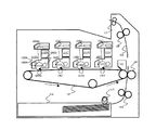
図1は、本実施例に係る画像形成装置の概略構成を示す断面図である。本実施例に係る画像形成装置は、複数色それぞれに対応した、静電潜像が形成される第1の像担持体(以下、「感光ドラム」と称す)と、静電潜像を現像する現像手段としての現像装置と、感光ドラム上に形成された各色の現像剤像を積層転写する第2の像担持体である中間転写体と、中間転写体上のフルカラー現像剤像を記録媒体としての転写材に一括転写する2次転写手段としての2次転写装置とを備える。 FIG. 1 is a cross-sectional view illustrating a schematic configuration of the image forming apparatus according to the present embodiment. The image forming apparatus according to the present embodiment develops an electrostatic latent image and a first image carrier (hereinafter referred to as a “photosensitive drum”) corresponding to each of a plurality of colors on which an electrostatic latent image is formed. A developing device as a developing means, an intermediate transfer member which is a second image carrier for transferring the developer images of the respective colors formed on the photosensitive drum, and a full color developer image on the intermediate transfer member as a recording medium And a secondary transfer device as secondary transfer means for batch transfer to the transfer material.
本実施例に係る画像形成装置は、ドラム状の電子写真感光体、即ち、感光ドラム101(Y、M、C、Bk)を回転可能に支持している。画像形成動作が開始すると、帯電手段としての帯電ローラ102(Y、M、C、Bk)は、感光ドラム101(Y、M、C、Bk)の表面を一様に帯電する。その後、露光手段としてのレーザー照射手段103(Y、M、C、Bk)が感光ドラム101(Y、M、C、Bk)表面を各色の画像情報に対応したレーザー光により露光を行い、感光ドラム101(Y、M、C、Bk)上に静電潜像を形成する。 The image forming apparatus according to this embodiment rotatably supports a drum-shaped electrophotographic photosensitive member, that is, a photosensitive drum 101 (Y, M, C, Bk). When the image forming operation is started, a charging roller 102 (Y, M, C, Bk) as a charging unit uniformly charges the surface of the photosensitive drum 101 (Y, M, C, Bk). Thereafter, the laser irradiation means 103 (Y, M, C, Bk) as the exposure means exposes the surface of the photosensitive drum 101 (Y, M, C, Bk) with laser light corresponding to the image information of each color, and the photosensitive drum An electrostatic latent image is formed on 101 (Y, M, C, Bk).
本実施例では、感光ドラム101(Y、M、C、Bk)の帯電電荷は負極性である。そして、画像情報に対応した静電潜像は、レーザー照射手段103(Y、M、C、Bk)からのレーザー光による露光によって、負極性の帯電電荷が減衰した部分に形成される。 In this embodiment, the charged charge on the photosensitive drum 101 (Y, M, C, Bk) is negative. Then, the electrostatic latent image corresponding to the image information is formed in a portion where the negative charged charge is attenuated by the exposure with the laser beam from the laser irradiation means 103 (Y, M, C, Bk).
その後、静電潜像は、感光ドラム101(Y、M、C、Bk)の回転に伴って、現像手段としての現像装置104(Y、M、C、Bk)が供給する現像剤の一種であるトナーにより可視化されて、感光ドラム101(Y、M、C、Bk)上にトナー像が形成される。次いで、各色の感光ドラム101(Y、M、C、Bk)に対応して配置される1次転写手段105(Y、M、C、Bk)により、感光ドラム101(Y、M、C、Bk)と中間転写体107とが当接する各々の1次転写部において、各色のトナー像が中間転写体107上に積層転写される。トナー像の転写を終了した感光ドラム101は、ブレード状のクリーニング手段を備えるクリーニング装置106(Y、M、C、Bk)によって、感光ドラム101(Y、M、C、Bk)表面に残留する転写残トナーが除去され、続く画像形成動作に備える。
Thereafter, the electrostatic latent image is a kind of developer supplied by the developing device 104 (Y, M, C, Bk) as a developing unit as the photosensitive drum 101 (Y, M, C, Bk) rotates. The toner image is visualized by a certain toner, and a toner image is formed on the photosensitive drum 101 (Y, M, C, Bk). Next, the photosensitive drum 101 (Y, M, C, Bk) is arranged by the primary transfer means 105 (Y, M, C, Bk) arranged corresponding to the photosensitive drum 101 (Y, M, C, Bk) of each color. ) And the
本実施例では、現像方式は反転現像方式である。そのため、帯電電荷と同極性(負極性)のトナーが、感光ドラム101(Y、M、C、Bk)上の負極性の帯電電荷が減衰した部分(画像部)に付着する。 In this embodiment, the developing method is a reversal developing method. Therefore, the toner having the same polarity (negative polarity) as the charged charge adheres to the portion (image portion) where the negative charged charge on the photosensitive drum 101 (Y, M, C, Bk) is attenuated.
また、各色の感光ドラム101、帯電ローラ102、現像装置104、クリーニング装置106は、各色ごとに一体的なプロセスカートリッジ110(Y、M、C、Bk)として構成され、画像形成装置に対し個別に交換可能な画像形成ステーションを形成している。トナーは、現像剤収容手段としてのトナー供給ユニット111(Y、M、C、Bk)から各色に応じて現像装置104(Y、M、C、Bk)へ補給される。 The photosensitive drum 101, the charging roller 102, the developing device 104, and the cleaning device 106 for each color are configured as an integral process cartridge 110 (Y, M, C, Bk) for each color, and are individually provided for the image forming apparatus. An exchangeable image forming station is formed. The toner is replenished to the developing device 104 (Y, M, C, Bk) according to each color from a toner supply unit 111 (Y, M, C, Bk) as a developer containing unit.
一方、転写材カセット114に収容された転写材113は、給紙ローラ115によって給紙され、レジストレーションローラ116により、中間転写体107上の画像と同期されて、中間転写体107と2次転写手段としての転写ローラ108とが当接する2次転写部へと搬送される。
On the other hand, the
そして、中間転写体107上のトナー像と転写材113とが2次転写部に至ると、転写ローラ108によって転写領域に形成される転写電界により、トナー像が転写材113上に転写される。その後、転写材113に担持された未定着トナー像は、定着装置109の備える定着手段(ヒートローラ)による加熱、及び、加圧手段による加圧を受けて、転写材113上に永久画像として定着される。
When the toner image on the
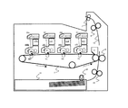
モノカラー画像形成時(モノカラーモード)では、図2のように、カラー画像形成ステーション(Y、M、C)におけるカラーのプロセスカートリッジ110(Y、M、C)の感光ドラム101(Y、M、C)と、中間転写体107を離間状態とし、カラーのプロセスカートリッジ110(Y、M、C)が駆動されない状態で、モノカラー画像形成が行われる。
At the time of mono color image formation (mono color mode), as shown in FIG. 2, the photosensitive drum 101 (Y, M) of the color process cartridge 110 (Y, M, C) in the color image forming station (Y, M, C) is used. , C) and the
本実施例に係る画像形成装置における、本発明に関係する各パラメータは以下のようになっている(図3参照)。 Each parameter related to the present invention in the image forming apparatus according to the present embodiment is as follows (see FIG. 3).
感光ドラム101上の露光位置(静電潜像書き込み位置)から1次転写部までの距離A=47mm
最下流(Bk)画像形成ステーションの1次転写部から、2次転写部までの距離B=510mm
画像形成領域の長さC=420mm(A3縦)
連続画像形成時の通常の非画像形成領域の長さD=50mm
中間転写体とカラーの画像形成ステーションとの当接離間動作に必要な時間T=0.5sec
プロセススピード(中間転写体の表面移動速度)V=150mm/sec
各画像形成ステーション間のピッチG=80mm
これにより、A3横プリント時(N=1)で、
B=510mm≧495mm=C+V×T+(C+D)×(N−1)
に設定されている。
Distance A from the exposure position (electrostatic latent image writing position) on the photosensitive drum 101 to the primary transfer portion A = 47 mm
Distance B = 510 mm from the primary transfer portion of the most downstream (Bk) image forming station to the secondary transfer portion
Image forming area length C = 420 mm (A3 length)
Normal non-image forming area length D during continuous image formation D = 50 mm
Time T / 0.5 sec required for contact / separation operation between the intermediate transfer member and the color image forming station
Process speed (surface transfer speed of the intermediate transfer member) V = 150 mm / sec
Pitch G = 80mm between each image forming station
As a result, during A3 landscape printing (N = 1),
B = 510 mm ≧ 495 mm = C + V × T + (C + D) × (N−1)
Is set to
また、当接離間時に中間転写体表面が移動する距離V×T=75mm、となっている。 Further, the distance V × T = 75 mm by which the surface of the intermediate transfer member moves during contact and separation.
次に本実施例におけるカラーモード切り替え時の制御に関して詳細に説明する。 Next, the control at the time of color mode switching in the present embodiment will be described in detail.
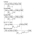
図4は本実施例に係る画像形成装置の制御ブロック図、図5はカラーモード切り替え時の制御フローチャート、図6、7は動作説明図である。 4 is a control block diagram of the image forming apparatus according to the present embodiment, FIG. 5 is a control flowchart at the time of color mode switching, and FIGS.
画像形成装置はユーザー(ホストコンピュータ120)からのプリント要求を受け取ると、プリントジョブを開始する(step1)。ホストコンピュータ120からの画像データを画像処理回路122によりプリント可能な各色ごとの画像情報に展開しながら、画像カラー判別手段123によりまず最初の画像がフルカラー画像かどうか判断する(step2)。フルカラー画像であった場合、プリント動作を行うカラーモード(本実施例の場合、カラー画像形成ステーションと中間転写体とを当接させて行う「フルカラーモード」と、カラーの画像形成ステーションと中間転写体とを離間させて行う「モノカラーモード」を持つ)を、フルカラーモードに設定する(step3)。モノカラー画像であった場合、次に続く1枚目の画像がどちらかを判断する(step4)。フルカラー画像であった場合、前記と同じくカラーモードを、フルカラーモードに設定する(step3)。モノカラー画像であった場合、カラーモードを、モノカラーモードに設定する(step5)。最初のカラーモードが設定されると、それに応じた画像形成シーケンスを選択する(step6)。 When the image forming apparatus receives a print request from the user (host computer 120), the image forming apparatus starts a print job (step 1). While developing the image data from the host computer 120 into image information for each color that can be printed by the image processing circuit 122, the image color discrimination means 123 first determines whether the first image is a full color image (step 2). A color mode in which a printing operation is performed for a full-color image (in this embodiment, a “full-color mode” in which a color image forming station and an intermediate transfer member are brought into contact with each other, a color image forming station and an intermediate transfer member Are set to the full color mode (step 3). If the image is a mono-color image, it is determined which one of the subsequent images is the next one (step 4). If the image is a full color image, the color mode is set to the full color mode as described above (step 3). If the image is a mono color image, the color mode is set to the mono color mode (step 5). When the first color mode is set, an image forming sequence corresponding to the color mode is selected (step 6).
フルカラーモードの場合、まず現在の画像をフルカラーモードで画像形成を開始する(step7)。次いで現在画像形成中の画像に続く1から3枚目の画像が何かを判断し、各条件により以降のシーケンスを選択する(step8、9、10、15)。
In the full color mode, first, image formation of the current image is started in the full color mode (step 7). Next, it is determined what the first to third images following the image currently being formed are, and the subsequent sequence is selected according to each condition (
全てがフルカラー画像の場合、また、モノカラー画像が1枚だけの場合、フルカラーモードによる連続プリント状態を維持する(step19)。次の1枚目、2枚目がモノカラー画像のとき(これはプリントジョブの最初にしかあり得ない)、最初のフルカラー画像形成直後に非画像形成領域を広げて(step16)、非画像形成領域部が最下流の画像ステーション(ブラック画像形成ステーション)110Bkの1次転写部を通過する際に、カラーモード切替手段としての中間転写体離間当接動作制御手段125によりカラー画像形成ステーションと中間転写体107の離間動作を行い、且つ以降のカラーモードをモノカラーモードに変更する(step17)。
If all are full-color images or if there is only one mono-color image, the continuous print state in the full-color mode is maintained (step 19). When the next first and second sheets are monocolor images (this can only occur at the beginning of the print job), the non-image formation area is expanded immediately after the first full-color image is formed (step 16), and non-image formation is performed. When the area portion passes through the primary transfer portion of the most downstream image station (black image forming station) 110Bk, the intermediate transfer body separation contact operation control means 125 as the color mode switching means causes the color image forming station and the intermediate transfer. The
広げる非画像形成領域Fは、1次転写部及び次の画像の静電潜像形成時に離間動作の影響が出ないことを考慮する必要があるため、離間の影響が考えられる距離V×T=75mmに、次の画像が感光ドラム101Bk上のレーザー103Bk照射部から1次転写部まで移動する距離A=47mmを足した距離V×T+A=122mm以上に設定する必要がある。本実施例ではマージン10mmを加えて、通常の非画像形成領域50mmに対して132mmに広げている。 The non-image forming area F to be expanded needs to consider that the influence of the separation operation does not occur at the time of forming the electrostatic latent image of the primary transfer portion and the next image. Therefore, the distance V × T = It is necessary to set the distance V × T + A = 122 mm or more by adding 75 mm to the distance A = 47 mm from which the next image moves from the laser 103Bk irradiation portion on the photosensitive drum 101Bk to the primary transfer portion. In this embodiment, a margin of 10 mm is added and the width is increased to 132 mm with respect to a normal non-image forming area of 50 mm.
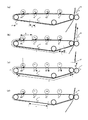
1枚目がフルカラー画像だが、2枚目、3枚目にモノカラー画像が続く場合、画像形成装置は本発明のカラーモード切替シーケンスに入る。以下、カラーモード切替シーケンスの動作を図6と合わせて説明する。 If the first sheet is a full-color image, but the mono-color image continues on the second sheet and the third sheet, the image forming apparatus enters the color mode switching sequence of the present invention. Hereinafter, the operation of the color mode switching sequence will be described with reference to FIG.
図6(a)はフルカラーモードでの通常連続画像形成状態を表す。 FIG. 6A shows a normal continuous image formation state in the full color mode.
まず切り替えシーケンスに入る際に、現在画像形成している画像の直後の非画像形成領域を、通常の非画像形成領域D=50mmから、E=85mmに広げる(step11、図6(b))。この広げられた非画像形成領域部Eは、中間転写体107のカラー画像形成ステーション(Y、M、C)からの離間時に2次転写部にあるべき領域なので、離間動作が画像形成に影響を与えると考えられる距離V×T=75mm以上に設定すればよく、本実施例ではマージン10mmを加えて85mmに広げている。
First, when entering the switching sequence, the non-image forming area immediately after the image currently formed is expanded from the normal non-image forming area D = 50 mm to E = 85 mm (step 11, FIG. 6B). Since the widened non-image forming area E is an area that should be in the secondary transfer portion when the
次いで、続く1枚目の画像をフルカラーモードのまま画像形成し(step12)、その直後の非画像形成領域をさらに、F=138mmに広げる(step13、図6(c))。広げる非画像形成領域Fは、1次転写部での転写及び次の画像の静電潜像形成時に離間動作の影響が出ないことを考慮する必要があるため、離間動作の影響が考えられる距離V×T=75mmに、次の画像が感光ドラム101Bk上のレーザー103Bk照射部から1次転写部まで移動する距離A=47mmを足した距離V×T+A=122mm以上に設定する必要がある。また同時に、非画像形成領域E部を2次転写部、非画像形成領域F部を最下流の画像ステーション(ブラック画像形成ステーション)110Bkの1次転写部に存在するようにしなくてはならない。その為には、
C+E+F≧A+B+V×T
を満たすように設定すればよく、非画像形成領域E決定後は非画像形成領域Fは、
F≧A+B+V×T−C−E
を満たせばよい。
Next, the next first image is formed in the full color mode (step 12), and the non-image forming area immediately after that is further expanded to F = 138 mm (
C + E + F ≧ A + B + V × T
The non-image forming area F is determined after the non-image forming area E is determined.
F ≧ A + B + V × TC-E
Should be satisfied.
よって、A+B+V×T−C−E=127mm以上に設定すればよい。前記V×T+A=122mmと比較して、127mm以上であれば両方の関係式を満たす為、本実施例ではマージン10mmを加えて137mmに広げている。 Therefore, A + B + V × TC-E = 127 mm or more may be set. Compared with V × T + A = 122 mm, if it is 127 mm or more, both relational expressions are satisfied. In this embodiment, the margin is increased to 137 mm with a margin of 10 mm.
その後、非画像形成領域E部が2次転写部、非画像形成領域F部が最下流の画像ステーション(ブラック画像形成ステーション)110Bkの1次転写部を通過する際に、中間転写体離間当接動作制御手段125によりカラー画像形成ステーション(Y、M、C)と中間転写体107の離間動作を行い、且つ以降のカラーモードをモノカラーモードに変更する(step14、図6(c))。
Thereafter, when the non-image forming area E passes through the secondary transfer portion and the non-image forming area F passes through the primary transfer portion of the most downstream image station (black image forming station) 110Bk, the intermediate transfer member is separated and contacted. The operation control means 125 separates the color image forming station (Y, M, C) from the
Step18において、続く画像形成の予定が無い場合、プリントジョブを終了し(step20)、ある場合は設定されたカラーモードに応じてプリント動作を継続していく(step19)。 If there is no plan for subsequent image formation in Step 18, the print job is terminated (Step 20), and if there is, the printing operation is continued according to the set color mode (Step 19).
次にStep6における画像形成シーケンスの選択の際に、モノカラーモードであった場合について説明する。 Next, the case where the mode is the mono color mode when the image forming sequence is selected in Step 6 will be described.
まず現在の画像をモノカラーモードで画像形成を開始する(step21)。次いで現在画像形成中の画像に続く1から3枚目の画像が何かを判断し、各条件により以降のシーケンスを選択する(step22、23)。 First, image formation of the current image is started in the mono color mode (step 21). Next, it is determined what the first to third images following the image currently being formed are, and the subsequent sequence is selected according to each condition (steps 22 and 23).
全てがモノカラー画像の場合、モノカラーモードによる連続プリント状態を維持する(step19)。次の2枚目がフルカラー画像のとき(これはプリントジョブの最初にしかありえない)、最初のモノカラー画像形成直後に非画像形成領域を広げて(step28)、非画像形成領域部が最下流の画像ステーション(ブラック画像形成ステーション)110Bkの1次転写部を通過する際に、中間転写体離間当接動作制御手段125によりカラー画像形成ステーションと中間転写体107の当接動作を行い、且つ以降のカラーモードをフルカラーモードに変更する(step29)。
When all the images are monochromatic images, the continuous printing state in the monochromatic mode is maintained (step 19). When the next second image is a full-color image (this can only occur at the beginning of the print job), the non-image forming area is widened immediately after the first mono-color image is formed (step 28), and the non-image forming area is the most downstream. When passing through the primary transfer portion of the image station (black image forming station) 110Bk, the intermediate transfer member separation contact operation control means 125 performs the contact operation between the color image forming station and the
広げる非画像形成領域Fは、1次転写部及び次の画像の静電潜像形成時に離間動作の影響が出ないことを考慮する必要があるため、離間動作の影響が考えられる距離V×T=75mmに、次の画像が感光ドラム101Bk上のレーザー103Bk照射部から1次転写部まで移動する距離A=47mmを足した距離V×T+A=122mm以上に設定する必要がある。本実施例ではマージン10mmを加えて、通常の非画像形成領域50mmに対して132mmに広げている。 The non-image forming area F to be expanded needs to consider that the influence of the separation operation does not occur at the time of forming the electrostatic latent image of the primary transfer portion and the next image. It is necessary to set the distance V × T + A = 122 mm or more by adding the distance A = 47 mm for moving the next image from the laser 103Bk irradiation portion on the photosensitive drum 101Bk to the primary transfer portion on the photosensitive drum 101Bk. In this embodiment, a margin of 10 mm is added and the width is increased to 132 mm with respect to a normal non-image forming area of 50 mm.
1、2枚目がモノカラー画像だが、3枚目にフルカラー画像が続く場合、画像形成装置は本発明のカラーモード切替シーケンスに入る。 When the first and second sheets are mono-color images but the third sheet is followed by a full-color image, the image forming apparatus enters the color mode switching sequence of the present invention.
まずカラーモード切替シーケンスに入る際に、現在画像形成している画像の直後の非画像形成領域を、通常の非画像形成領域D=50mmから、E=85mmに広げる(step24)。この広げられた非画像形成領域部Eは、中間転写体107の離間時に2次転写部に当たる領域なので、離間動作の影響が考えられる距離V×T=75mm以上に設定すればよく、本実施例ではマージン10mmを加えて85mmに広げている。
First, when entering the color mode switching sequence, the non-image forming area immediately after the image currently being formed is expanded from the normal non-image forming area D = 50 mm to E = 85 mm (step 24). Since the widened non-image forming area E is an area that hits the secondary transfer portion when the
次いで、続く1枚目の画像をモノカラーモードのまま画像形成し(step25)、その直後の非画像形成領域をさらに、F=138mmに広げる(step26)。広げる非画像形成領域Fは、1次転写部及び次の画像の静電潜像形成時に離間動作の影響が出ないことを考慮する必要があるため、離間動作の影響が考えられる距離V×T=75mmに、次の画像が感光ドラム101Bk上のレーザー103Bk照射部から1次転写部まで移動する距離A=47mmを足した距離V×T+A=122mm以上に設定する必要がある。また同時に、非画像形成領域E部を2次転写部、非画像形成領域F部を最下流の画像ステーション(ブラック画像形成ステーション)110Bkの1次転写部に存在するようにしなくてはならない。その為には、
C+E+F≧A+B+V×T
を満たすように設定すればよく、非画像形成領域E決定後は非画像形成領域Fは、
F≧A+B+V×T−C−E
を満たせばよい。
Next, the subsequent first image is formed in the mono color mode (step 25), and the non-image forming area immediately after that is further expanded to F = 138 mm (step 26). The non-image forming area F to be expanded needs to consider that the influence of the separation operation does not occur at the time of forming the electrostatic latent image of the primary transfer portion and the next image. Therefore, the distance V × T where the influence of the separation operation can be considered. It is necessary to set the distance V × T + A = 122 mm or more by adding the distance A = 47 mm for moving the next image from the laser 103Bk irradiation portion on the photosensitive drum 101Bk to the primary transfer portion on the photosensitive drum 101Bk. At the same time, the non-image forming area E must be present in the secondary transfer portion and the non-image forming area F in the primary transfer portion of the most downstream image station (black image forming station) 110Bk. To that end,
C + E + F ≧ A + B + V × T
The non-image forming area F is determined after the non-image forming area E is determined.
F ≧ A + B + V × TC-E
Should be satisfied.
よって、A+B+V×T−C−E=127mm以上に設定すればよい。前記V×T+A=122mmと比較して、127mm以上であれば両方の関係式を満たす為、本実施例ではマージン10mmを加えて137mmに広げている。 Therefore, A + B + V × TC-E = 127 mm or more may be set. Compared with V × T + A = 122 mm, if it is 127 mm or more, both relational expressions are satisfied. In this embodiment, the margin is increased to 137 mm with a margin of 10 mm.
その後、非画像形成領域E部が2次転写部、非画像形成領域F部が最下流の画像ステーション(ブラック画像形成ステーション)110Bkの1次転写部を通過する際に、中間転写体離間当接動作制御手段125によりカラー画像形成ステーションと中間転写体107の当接動作を行い、且つ以降のカラーモードをフルカラーモードに変更する(step27)。
Thereafter, when the non-image forming area E passes through the primary transfer section of the secondary transfer section and the non-image forming area F section passes through the primary transfer section of the most downstream image station (black image forming station) 110Bk, the intermediate transfer member is separated and contacted. The operation control means 125 performs a contact operation between the color image forming station and the
Step18において、続く画像形成の予定が無い場合、プリントジョブを終了し(step20)、予定がある場合は設定されたカラーモードに応じてプリント動作を継続していく(step19)。 In Step 18, if there is no plan for subsequent image formation, the print job is terminated (Step 20), and if there is a plan, the printing operation is continued according to the set color mode (Step 19).
以上が、本実施例のカラーモード切り替え時の制御である。 The above is the control at the time of color mode switching of the present embodiment.
この様な構成、制御を行うことにより、従来に対してカラーモード切り替えにかかる時間を大幅に短縮することが出来る。このことを、図7を用いて比較説明する。 By performing such a configuration and control, the time required for color mode switching can be significantly shortened compared to the prior art. This will be described with reference to FIG.
図7のフルカラー連続4枚プリント時(モノカラーでも同じ)と、従来例のフルカラー→モノカラーモード切替時、モノカラーモード→フルカラーモード切替時を比較すると、1箇所の非画像形成領域がDから大きく広がっている。この量は画像が2次転写部を抜け切る量と、中間転写体の離間動作の影響を考慮した距離である為、フルカラー→モノカラーモード切替時では、
B+V×T+A、
モノカラー→フルカラーモード切替時では、さらにカラー画像形成ステーション移動分G×3が加わり、
B+V×T+A+G×3
が最低でも必要である。これは、本実施例の画像形成装置に適応した場合、フルカラー→モノカラーモード切替時で距離632mm(連続プリント時に対し582mm/3.88secの増加)、モノカラー→フルカラーモード切替時で872mm(連続プリント時に対し822mm/5.48secの増加)である。
When comparing the full-color continuous four-sheet printing in FIG. 7 (same for mono-color) with the conventional full-color → mono-color mode switching and mono-color mode → full-color mode switching, one non-image forming area is from D Widely spread. This amount is a distance considering the amount of the image that passes through the secondary transfer portion and the effect of the separation operation of the intermediate transfer member, so when switching from full color to mono color mode,
B + V × T + A,
At the time of switching from mono color to full color mode, the color image forming station movement G × 3 is added,
B + V × T + A + G × 3
Is required at a minimum. When this is applied to the image forming apparatus of the present embodiment, the distance is 632 mm (increase of 582 mm / 3.88 sec compared with continuous printing) when switching from full color to mono color mode, and 872 mm (continuous when switching from mono color to full color mode). 822 mm / 5.48 sec increase with respect to printing).
これに対し、本実施例のカラーモード切替時では、両切替シーケンス(フルカラー→モノカラーモード及びモノカラー→フルカラーモード)ともに2箇所の非画像形成領域がD→E、D→Fに広がっている。本実施例ではこの広がった量は、E+F−D×2=85+137−50×2=123mmであり、時間にして0.81secの増加に大幅に抑えられている。 On the other hand, when the color mode is switched in this embodiment, the two non-image forming areas are spread from D to E and from D to F in both switching sequences (full color → mono color mode and mono color → full color mode). . In this embodiment, the spread amount is E + F−D × 2 = 85 + 137−50 × 2 = 123 mm, and is greatly suppressed to an increase of 0.81 sec over time.
これにより、ユーザーはフルカラー画像、モノカラー画像が混在したプリントを行ったり、またネットワーク接続等で複数のユーザーが様々な画像をプリントした際に、カラーモードの切り替えの為に待たされる時間が大幅に減り、より快適なプリント環境を構築することが可能である。 As a result, when a user prints a mixture of full-color images and mono-color images, or when multiple users print various images over a network connection, the time spent waiting for switching the color mode is greatly increased. Therefore, it is possible to construct a more comfortable printing environment.
また、切り替え時間が大幅に短縮されたことにより、画像形成ステーション(プロセスカートリッジ)の回転を抑制できる為、消耗品の消耗を抑制できるというメリットも同時に得られる。 Further, since the switching time is greatly shortened, the rotation of the image forming station (process cartridge) can be suppressed, so that the advantage that consumption of consumables can be suppressed is also obtained.
なお、本実施例における非画像形成領域の調整は、非画像形成領域長さ調整手段としてのCPU121により行われる。
Note that the adjustment of the non-image forming area in this embodiment is performed by the
実施例1では、前記した構成寸法と画像寸法等により、最下流(Bk)画像形成ステーションの1次転写部から2次転写部までの距離Bに画像が1枚入る構成について説明を行った。これに対し、画像が小さく2枚以上入る場合、又は最下流(Bk)画像形成ステーションの1次転写部から2次転写部までの距離Bが大きくて画像が2枚以上入る場合、入る枚数をNと定義することで、本発明の効果が得られる構成を以下のように示すことが出来る。 In the first embodiment, the configuration in which one image enters the distance B from the primary transfer portion to the secondary transfer portion of the most downstream (Bk) image forming station has been described based on the above-described configuration dimensions, image dimensions, and the like. On the other hand, when two or more images are small, or when the distance B from the primary transfer unit to the secondary transfer unit of the most downstream (Bk) image forming station is large and two or more images are included, the number of sheets to be entered is By defining N, a configuration that can achieve the effects of the present invention can be shown as follows.
すなわち、
感光ドラム101上の露光位置から1次転写部までの距離A
最下流(Bk)画像形成ステーションの1次転写部から、2次転写部までの距離B
画像形成領域の長さC
連続画像形成時の通常の非画像形成領域の長さD
第2の像担持体とカラーの画像形成ステーションとの当接離間動作に必要な時間T
プロセススピード(中間転写体の表面移動速度)V
当接離間時に中間転写体表面が移動する距離V×T
において、
B≧C+V×T+(C+D)×(N−1)
C×N+E+F≧A+B+V×T
E≧V×T
F≧V×T+A
を満たし、
現在形成している画像より、(N+2)枚先までの画像のフルカラーかモノカラーかを判別する手段を持ち、
現在がフルカラーモードである場合、画像カラー判別手段により判別された現在の画像に続く(N+1)枚目、(N+2)枚目がモノカラー画像であった場合、図8に示すように、現在形成している画像の直後の非画像形成領域、及び現在の画像に続くN枚目の直後の非画像形成領域を広げることにより、2次転写部と、最下流の画像形成ステーションの1次転写部とにおいて、拡張した前記非画像形成領域が存在する状態を作り出し、この状態において、中間転写体とカラーの画像形成ステーションとを離間させること、
現在がモノカラーモードである場合、画像カラー判別手段により判別された現在の画像に続く(N+2)枚目がフルカラー画像であった場合、同じく図8に示すように、現在形成している画像の直後の非画像形成領域、及び現在の画像に続くN枚目の直後の非画像形成領域を広げることにより、2次転写部と、最下流の画像形成ステーションの1次転写部とにおいて、拡張した前記非画像形成領域領域が存在する状態を作り出し、この状態において、中間転写体とカラーの画像形成ステーションとを当接させること、
により、本発明の効果が得られる。
That is,
Distance A from the exposure position on the photosensitive drum 101 to the primary transfer portion A
Distance B from the primary transfer portion to the secondary transfer portion of the most downstream (Bk) image forming station
Length of image forming area C
Length D of normal non-image forming area during continuous image formation
Time T required for the contact / separation operation between the second image carrier and the color image forming station
Process speed (surface transfer speed of intermediate transfer member) V
Distance V × T that the surface of the intermediate transfer member moves when contacting and separating
In
B ≧ C + V × T + (C + D) × (N−1)
C × N + E + F ≧ A + B + V × T
E ≧ V × T
F ≧ V × T + A
The filling,
Has a means to determine whether the image up to (N + 2) sheets ahead of the currently formed image is full color or mono color,
When the current mode is the full color mode, when the (N + 1) th and (N + 2) th sheets following the current image determined by the image color determination unit are monocolor images, as shown in FIG. The secondary transfer unit and the primary transfer unit of the most downstream image forming station by expanding the non-image forming region immediately after the current image and the non-image forming region immediately after the Nth sheet following the current image. And creating a state in which the expanded non-image forming region exists, and in this state, separating the intermediate transfer member from the color image forming station,
When the current mode is the mono-color mode, if the (N + 2) th image following the current image determined by the image color determination unit is a full-color image, as shown in FIG. By expanding the non-image forming area immediately after and the non-image forming area immediately after the Nth sheet following the current image, the secondary transfer portion and the primary transfer portion of the most downstream image forming station expanded. Creating a state in which the non-image forming area is present, and in this state, bringing the intermediate transfer member and a color image forming station into contact with each other;
Thus, the effect of the present invention can be obtained.
1、101 感光ドラム(第1の像担持体に対応)
2、102 帯電ローラ
3、103 レーザー照射手段
4、104 現像装置(現像手段に対応)
5、105 1次転写手段
6、106 クリーニング装置
7、107 中間転写体(第2の像担持体に対応)
8、108 2次転写手段
9、109 定着装置
10、110 画像形成ステーション
11、111 トナー供給ユニット
13、113 転写材(記録媒体に対応)
121 CPU(非画像形成領域長さ調整手段に対応)
123 画像カラー判別手段
125 中間転写体離間当接動作制御手段(カラーモード切替手段に対応)
1, 101 Photosensitive drum (corresponding to the first image carrier)
2, 102 Charging roller 3, 103 Laser irradiation means 4, 104 Developing device (corresponding to developing means)
5, 105 Primary transfer means 6, 106
8, 108 Secondary transfer means 9, 109 Fixing device 10, 110 Image forming station 11, 111
121 CPU (corresponding to non-image forming area length adjusting means)
123 Image color discriminating means 125 Intermediate transfer member separation contact operation control means (corresponding to color mode switching means)
Claims (5)
前記複数の像坦持体の夫々に形成された複数の前記静電潜像を、色の異なる画像として現像する複数の現像手段と、
前記複数の現像手段によって現像された前記色の異なる画像を担持する中間転写体と、
前記複数の像担持体の夫々に形成された色の異なる画像を前記中間転写体に順次重ねて1次転写する複数の1次転写手段と、
前記中間転写体に順次重ねて1次転写された画像を記録媒体に2次転写する2次転写手段とを有し、
前記中間転写体上に複数の画像を連続して1次転写する際に、前記中間転写体に1次転写される複数の画像の画像間隔を第1間隔に設定する設定手段とを有し、前記複数の像坦持体と前記複数の現像手段を用いてフルカラー画像を形成するフルカラーモードと、前記複数の像坦持体のうち1つの像坦持体と、該1つの像坦持体に対応する1つの現像手段を用いてモノカラー画像を形成するモノカラーモードを切り替えることが可能な画像形成装置であって、
前記モノカラーモードから前記フルカラーモードへ、または、前記フルカラーモードから前記モノカラーモードへモードを切り替える際に、
前記設定手段は、切り替え前のモードで前記中間転写体に最後に1次転写される画像と該最後に1次転写される画像の1つ前に1次転写される画像の前記画像間隔を前記第1間隔よりも広い第2間隔に設定し、更に、前記最後に1次転写される画像と、切り替え後のモードで前記中間転写体に最初に1次転写される画像の前記画像間隔を前記第2間隔よりも広い第3間隔になるように設定することによって、
前記中間転写体上における前記第2間隔に対応する非画像形成領域が前記中間転写体と前記2次転写手段とで形成される2次転写部に位置し、かつ、前記第3間隔に対応する非画像形成領域が複数の前記像坦持体の中で最後に画像を前記中間転写体に1次転写する像坦持体と前記中間転写体とで形成される1次転写部に位置する切り替え状態を作ることを特徴とする画像形成装置。 A plurality of image carriers on which electrostatic latent images are formed;
A plurality of developing means for developing a plurality of said electrostatic latent image formed on each of the plurality of image carrier, as different images in color,
An intermediate transfer member carrying the images of different colors developed by the plurality of developing means ;
A plurality of primary transfer means for sequentially transferring images of different colors formed on each of the plurality of image carriers on the intermediate transfer body in sequence and performing primary transfer ;
Secondary transfer means for secondary transfer to the recording medium the image that has been primary transferred in sequence on the intermediate transfer body ,
Setting means for setting the image interval of the plurality of images primarily transferred to the intermediate transfer member to a first interval when the plurality of images are continuously primary-transferred onto the intermediate transfer member; A full-color mode for forming a full-color image using the plurality of image carriers and the plurality of developing units, one image carrier among the plurality of image carriers, and the one image carrier an image forming apparatus capable of switching the mono-color mode for forming a monochromatic image using a corresponding one of the developing means,
When switching the mode from the mono color mode to the full color mode, or from the full color mode to the mono color mode,
The setting means sets the image interval between the image that is finally primarily transferred to the intermediate transfer body in the mode before switching and the image that is primarily transferred immediately before the image that is primarily transferred first. A second interval wider than the first interval is set, and the image interval between the image that is primarily transferred last and the image that is first transferred first to the intermediate transfer member in the mode after switching is set as the image interval. By setting to be a third interval wider than the second interval,
A non-image forming area corresponding to the second interval on the intermediate transfer member is located in a secondary transfer portion formed by the intermediate transfer member and the secondary transfer unit, and corresponds to the third interval. Non-image forming region is switched to a primary transfer portion formed by the intermediate transfer body and the image transfer body that primarily transfers the image to the intermediate transfer body last among the plurality of the image support bodies. state image forming apparatus comprising create Rukoto a.
前記モノカラーモードから前記フルカラーモードに切り替える際に、前記切り替え状態において、前記中間転写体から離間している像坦持体を前記中間転写体に当接させることを特徴とする請求項1に記載の画像形成装置。 2. The image bearing member spaced apart from the intermediate transfer member is brought into contact with the intermediate transfer member in the switching state when switching from the mono color mode to the full color mode. Image forming apparatus.
前記1次転写部から前記2次転写部までの距離をB、
前記複数の画像の夫々の長さをC、
前記第2間隔をE、
前記第3間隔をF、前記中間転写体と前記像担持体との当接離間動作に必要な時間をT、
前記中間転写体の表面移動速度をV、
としたときに、
B≧C+V×T、
であり、
E≧V×T、
F≧V×T+A、
C+E+F≧A+B+V×T、
となるようにEとFを設定することを特徴とする請求項1または2に記載の画像形成装置。 The distance from the formation start position of the electrostatic latent image of the image carrier to which the image is finally transferred to the intermediate transfer body among the plurality of image carriers to the primary transfer portion is A,
The distance from the primary transfer portion to the secondary transfer portion is B,
The length of each of the plurality of images is C,
The second interval is E,
F is the third interval , T is the time required for the contact and separation of the intermediate transfer member and the image carrier ,
The surface transfer speed of the intermediate transfer member is V,
And when
B ≧ C + V × T,
And
E ≧ V × T,
F ≧ V × T + A,
C + E + F ≧ A + B + V × T,
The image forming apparatus according to claim 1 or 2, characterized in that setting the E and F such that.
前記第1間隔をDとし、
前記中間転写体上において、前記1次転写部から前記2次転写部までの間に含まれる画像の数を整数Nとしたときに、
B≧C+V×T+(C+D)×(N−1)
を満たすNにおいて、
前記画像カラー判別手段が、現在、現像している画像より、(N+2)枚先までの画像がフルカラーかモノカラーかを判別し、
現在がフルカラーモードであり、且つ前記画像カラー判別手段により判別された現在の画像に続く(N+1)枚目、(N+2)枚目の画像がモノカラー画像であった場合、
前記第2間隔と前記第3間隔を調整して、前記1次転写部と前記2次転写部との間にN個の画像が存在し、且つ、前記1次転写部に前記第3間隔に対応する非画像形成領域が存在し、前記2次転写部に前記第2間隔に対応する非画像形成領域が存在する状態を作ることを特徴とする請求項3に記載の画像形成装置。 Having image color discrimination means,
The first interval is D,
On the intermediate transfer member, when the number of images included between the primary transfer portion and the secondary transfer portion is an integer N,
B ≧ C + V × T + (C + D) × (N−1)
In N satisfying
The image color discrimination means discriminates whether the image up to (N + 2) sheets ahead of the currently developed image is full color or mono color,
When the current mode is the full color mode and the (N + 1) th and (N + 2) th images following the current image determined by the image color determination unit are monocolor images,
Adjust the third gap and said second gap, N pieces of images is present between the primary transfer unit and the secondary transfer unit, and the third distance to the primary transfer portion the image forming apparatus according to claim 3 in which the non-image forming area corresponding exists, wherein the Ru create a state where the non-image forming area corresponding to the second distance to the secondary transfer unit is present.
前記第1間隔をDとし、
前記1次転写部から前記2次転写部までの間に含まれる画像形成領域の数を整数Nとしたときに、
B≧C+V×T+(C+D)×(N−1)
を満たすNにおいて、
前記画像カラー判別手段が、現在、現像している画像より、(N+2)枚先までの画像がフルカラーかモノカラーかを判別し、
現在がモノカラーモードであり、且つ、前記画像カラー判別手段により判別された現在の画像に続く(N+2)枚目の画像がフルカラー画像であった場合、
前記第2間隔と前記第3間隔を調整して、前記1次転写部と前記2次転写部との間にN個の画像形成領域が存在し、且つ、前記1次転写部に前記第3間隔に対応する非画像形成領域と前記2次転写部に前記第2間隔に対応する非画像形成領域が存在する状態を作ることを特徴とする請求項3に記載の画像形成装置。 Having image color discrimination means,
The first interval is D,
When the number of image forming regions included between the primary transfer portion and the secondary transfer portion is an integer N,
B ≧ C + V × T + (C + D) × (N−1)
In N satisfying
The image color discrimination means discriminates whether the image up to (N + 2) sheets ahead of the currently developed image is full color or mono color,
When the current mode is a mono color mode and the (N + 2) -th image following the current image determined by the image color determination unit is a full-color image,
Adjust the third gap and said second gap, there are N image forming region between the primary transfer unit and the secondary transfer unit, and the third to the primary transfer portion the image forming apparatus according to claim 3, wherein the non-imaging region corresponding to the second distance be Ru create the conditions present in said secondary transfer part and the non-image forming region corresponding to the interval.
Priority Applications (6)
| Application Number | Priority Date | Filing Date | Title |
|---|---|---|---|
| JP2004358565A JP4649189B2 (en) | 2004-12-10 | 2004-12-10 | Image forming apparatus |
| US11/295,077 US7349658B2 (en) | 2004-12-10 | 2005-12-06 | Image forming apparatus that has a full-color mode and a monocolor mode, and image forming apparatus that can adjust the length of a non-image forming region during mode switching state |
| KR1020050120411A KR100776838B1 (en) | 2004-12-10 | 2005-12-09 | Image forming apparatus |
| DE602005026493T DE602005026493D1 (en) | 2004-12-10 | 2005-12-09 | Image forming device with change between color printing and monochrome printing mode |
| EP05257585A EP1674942B1 (en) | 2004-12-10 | 2005-12-09 | Image formation apparatus with switching between color printing mode and monochrome printing mode |
| CNB2005101304325A CN100435039C (en) | 2004-12-10 | 2005-12-09 | Image formation apparatus |
Applications Claiming Priority (1)
| Application Number | Priority Date | Filing Date | Title |
|---|---|---|---|
| JP2004358565A JP4649189B2 (en) | 2004-12-10 | 2004-12-10 | Image forming apparatus |
Publications (3)
| Publication Number | Publication Date |
|---|---|
| JP2006163287A JP2006163287A (en) | 2006-06-22 |
| JP2006163287A5 JP2006163287A5 (en) | 2008-01-24 |
| JP4649189B2 true JP4649189B2 (en) | 2011-03-09 |
Family
ID=36010887
Family Applications (1)
| Application Number | Title | Priority Date | Filing Date |
|---|---|---|---|
| JP2004358565A Expired - Fee Related JP4649189B2 (en) | 2004-12-10 | 2004-12-10 | Image forming apparatus |
Country Status (6)
| Country | Link |
|---|---|
| US (1) | US7349658B2 (en) |
| EP (1) | EP1674942B1 (en) |
| JP (1) | JP4649189B2 (en) |
| KR (1) | KR100776838B1 (en) |
| CN (1) | CN100435039C (en) |
| DE (1) | DE602005026493D1 (en) |
Families Citing this family (10)
| Publication number | Priority date | Publication date | Assignee | Title |
|---|---|---|---|---|
| JP4652798B2 (en) * | 2004-12-17 | 2011-03-16 | キヤノン株式会社 | Color image forming apparatus |
| JP2007199131A (en) * | 2006-01-24 | 2007-08-09 | Fuji Xerox Co Ltd | Image forming apparatus |
| JP4943194B2 (en) * | 2007-03-15 | 2012-05-30 | 株式会社東芝 | Image forming apparatus and image forming method |
| US7801455B2 (en) * | 2007-12-21 | 2010-09-21 | Xerox Corporation | Architecture for a multi toner printing system |
| US8005391B2 (en) * | 2008-03-17 | 2011-08-23 | Lexmark International, Inc. | Methods for determining when to transition between color printing and black-only printing in an image forming device |
| JP2012063631A (en) * | 2010-09-16 | 2012-03-29 | Ricoh Co Ltd | Image forming device |
| JP5640860B2 (en) * | 2011-03-29 | 2014-12-17 | コニカミノルタ株式会社 | Image forming apparatus |
| JP6494372B2 (en) * | 2015-03-31 | 2019-04-03 | キヤノン株式会社 | Image forming apparatus |
| JP6808371B2 (en) * | 2016-06-21 | 2021-01-06 | キヤノン株式会社 | Image forming device |
| JP2019117302A (en) * | 2017-12-27 | 2019-07-18 | 株式会社沖データ | Image forming device |
Citations (4)
| Publication number | Priority date | Publication date | Assignee | Title |
|---|---|---|---|---|
| JPH1172989A (en) * | 1997-08-29 | 1999-03-16 | Minolta Co Ltd | Image forming device |
| JP2001331013A (en) * | 2000-05-18 | 2001-11-30 | Canon Inc | Image forming device |
| JP2003057911A (en) * | 2001-08-21 | 2003-02-28 | Minolta Co Ltd | Image forming device |
| JP2004004398A (en) * | 2002-06-03 | 2004-01-08 | Matsushita Electric Ind Co Ltd | Color image forming apparatus |
Family Cites Families (8)
| Publication number | Priority date | Publication date | Assignee | Title |
|---|---|---|---|---|
| JP4183219B2 (en) * | 1999-12-21 | 2008-11-19 | フジノン株式会社 | A fringe analysis method using Fourier transform |
| JP2003149901A (en) * | 2001-11-16 | 2003-05-21 | Sharp Corp | Color image forming device and method for controlling device thereof |
| JP3977129B2 (en) * | 2002-04-16 | 2007-09-19 | キヤノン株式会社 | Image forming apparatus |
| JP2003337454A (en) * | 2002-05-21 | 2003-11-28 | Fuji Xerox Co Ltd | Image forming apparatus |
| WO2003102697A2 (en) | 2002-06-03 | 2003-12-11 | Matsushita Electric Industrial Co., Ltd. | Color image forming apparatus |
| JP2004029057A (en) * | 2002-06-21 | 2004-01-29 | Canon Inc | Image forming apparatus |
| US7085524B2 (en) * | 2002-11-29 | 2006-08-01 | Canon Kabushiki Kaisha | Image forming apparatus |
| EP1431837B1 (en) * | 2002-12-20 | 2014-12-03 | Ricoh Company, Ltd. | A colour image forming apparatus with installable process cartridges |
-
2004
- 2004-12-10 JP JP2004358565A patent/JP4649189B2/en not_active Expired - Fee Related
-
2005
- 2005-12-06 US US11/295,077 patent/US7349658B2/en active Active
- 2005-12-09 EP EP05257585A patent/EP1674942B1/en not_active Expired - Fee Related
- 2005-12-09 DE DE602005026493T patent/DE602005026493D1/en active Active
- 2005-12-09 CN CNB2005101304325A patent/CN100435039C/en not_active Expired - Fee Related
- 2005-12-09 KR KR1020050120411A patent/KR100776838B1/en active IP Right Grant
Patent Citations (4)
| Publication number | Priority date | Publication date | Assignee | Title |
|---|---|---|---|---|
| JPH1172989A (en) * | 1997-08-29 | 1999-03-16 | Minolta Co Ltd | Image forming device |
| JP2001331013A (en) * | 2000-05-18 | 2001-11-30 | Canon Inc | Image forming device |
| JP2003057911A (en) * | 2001-08-21 | 2003-02-28 | Minolta Co Ltd | Image forming device |
| JP2004004398A (en) * | 2002-06-03 | 2004-01-08 | Matsushita Electric Ind Co Ltd | Color image forming apparatus |
Also Published As
| Publication number | Publication date |
|---|---|
| EP1674942B1 (en) | 2011-02-23 |
| JP2006163287A (en) | 2006-06-22 |
| EP1674942A2 (en) | 2006-06-28 |
| CN100435039C (en) | 2008-11-19 |
| DE602005026493D1 (en) | 2011-04-07 |
| US20060127139A1 (en) | 2006-06-15 |
| KR100776838B1 (en) | 2007-11-16 |
| KR20060065547A (en) | 2006-06-14 |
| US7349658B2 (en) | 2008-03-25 |
| CN1786841A (en) | 2006-06-14 |
| EP1674942A3 (en) | 2008-01-16 |
Similar Documents
| Publication | Publication Date | Title |
|---|---|---|
| US7349658B2 (en) | Image forming apparatus that has a full-color mode and a monocolor mode, and image forming apparatus that can adjust the length of a non-image forming region during mode switching state | |
| US7542690B2 (en) | Color image forming apparatus, and program and method of controlling a color image forming apparatus | |
| JP4369111B2 (en) | Electrophotographic cluster printing system | |
| JP2000066475A (en) | Image forming device | |
| JP4072532B2 (en) | Image forming apparatus | |
| JP4164503B2 (en) | Image forming apparatus. | |
| JP4834334B2 (en) | Image forming apparatus | |
| JP2004118167A (en) | Image forming apparatus | |
| JP3799245B2 (en) | Image forming apparatus | |
| JPH07306561A (en) | Tandem engine type color image forming device | |
| JP3671779B2 (en) | Color image forming apparatus and color image forming method | |
| JP3754937B2 (en) | Image forming apparatus and image forming method | |
| JP5017994B2 (en) | Image forming apparatus | |
| JP2023178030A (en) | Image forming apparatus | |
| JP2004237611A (en) | Printer | |
| JP2614736B2 (en) | Multicolor image forming device | |
| JP3658592B2 (en) | Image forming apparatus | |
| JP2000035706A (en) | Image forming device | |
| JPH07134531A (en) | Operation control method for copying machine | |
| JP2000029314A (en) | Image forming device | |
| JP2006267681A (en) | Image forming apparatus | |
| JP2004171037A (en) | Image forming apparatus | |
| JPH11194579A (en) | Image forming device | |
| JPH0467188A (en) | Color printer | |
| JP2001249515A (en) | Developing method, developing device and multicolor image forming device |
Legal Events
| Date | Code | Title | Description |
|---|---|---|---|
| A521 | Request for written amendment filed |
Free format text: JAPANESE INTERMEDIATE CODE: A523 Effective date: 20071205 |
|
| A621 | Written request for application examination |
Free format text: JAPANESE INTERMEDIATE CODE: A621 Effective date: 20071205 |
|
| A131 | Notification of reasons for refusal |
Free format text: JAPANESE INTERMEDIATE CODE: A131 Effective date: 20100608 |
|
| A521 | Request for written amendment filed |
Free format text: JAPANESE INTERMEDIATE CODE: A523 Effective date: 20100809 |
|
| TRDD | Decision of grant or rejection written | ||
| A01 | Written decision to grant a patent or to grant a registration (utility model) |
Free format text: JAPANESE INTERMEDIATE CODE: A01 Effective date: 20101207 |
|
| A01 | Written decision to grant a patent or to grant a registration (utility model) |
Free format text: JAPANESE INTERMEDIATE CODE: A01 |
|
| A61 | First payment of annual fees (during grant procedure) |
Free format text: JAPANESE INTERMEDIATE CODE: A61 Effective date: 20101213 |
|
| FPAY | Renewal fee payment (event date is renewal date of database) |
Free format text: PAYMENT UNTIL: 20131217 Year of fee payment: 3 |
|
| R150 | Certificate of patent or registration of utility model |
Ref document number: 4649189 Country of ref document: JP Free format text: JAPANESE INTERMEDIATE CODE: R150 Free format text: JAPANESE INTERMEDIATE CODE: R150 |
|
| LAPS | Cancellation because of no payment of annual fees |