JP4647096B2 - Method and system for configuring a computer to connect to a network using a network connection object - Google Patents
Method and system for configuring a computer to connect to a network using a network connection object Download PDFInfo
- Publication number
- JP4647096B2 JP4647096B2 JP2000521445A JP2000521445A JP4647096B2 JP 4647096 B2 JP4647096 B2 JP 4647096B2 JP 2000521445 A JP2000521445 A JP 2000521445A JP 2000521445 A JP2000521445 A JP 2000521445A JP 4647096 B2 JP4647096 B2 JP 4647096B2
- Authority
- JP
- Japan
- Prior art keywords
- network
- connection
- configuration information
- computer
- user
- Prior art date
- Legal status (The legal status is an assumption and is not a legal conclusion. Google has not performed a legal analysis and makes no representation as to the accuracy of the status listed.)
- Expired - Lifetime
Links
Images


Classifications
-
- H—ELECTRICITY
- H04—ELECTRIC COMMUNICATION TECHNIQUE
- H04L—TRANSMISSION OF DIGITAL INFORMATION, e.g. TELEGRAPHIC COMMUNICATION
- H04L67/00—Network arrangements or protocols for supporting network services or applications
- H04L67/34—Network arrangements or protocols for supporting network services or applications involving the movement of software or configuration parameters
-
- Y—GENERAL TAGGING OF NEW TECHNOLOGICAL DEVELOPMENTS; GENERAL TAGGING OF CROSS-SECTIONAL TECHNOLOGIES SPANNING OVER SEVERAL SECTIONS OF THE IPC; TECHNICAL SUBJECTS COVERED BY FORMER USPC CROSS-REFERENCE ART COLLECTIONS [XRACs] AND DIGESTS
- Y10—TECHNICAL SUBJECTS COVERED BY FORMER USPC
- Y10S—TECHNICAL SUBJECTS COVERED BY FORMER USPC CROSS-REFERENCE ART COLLECTIONS [XRACs] AND DIGESTS
- Y10S707/00—Data processing: database and file management or data structures
- Y10S707/99931—Database or file accessing
- Y10S707/99937—Sorting
-
- Y—GENERAL TAGGING OF NEW TECHNOLOGICAL DEVELOPMENTS; GENERAL TAGGING OF CROSS-SECTIONAL TECHNOLOGIES SPANNING OVER SEVERAL SECTIONS OF THE IPC; TECHNICAL SUBJECTS COVERED BY FORMER USPC CROSS-REFERENCE ART COLLECTIONS [XRACs] AND DIGESTS
- Y10—TECHNICAL SUBJECTS COVERED BY FORMER USPC
- Y10S—TECHNICAL SUBJECTS COVERED BY FORMER USPC CROSS-REFERENCE ART COLLECTIONS [XRACs] AND DIGESTS
- Y10S707/00—Data processing: database and file management or data structures
- Y10S707/99931—Database or file accessing
- Y10S707/99939—Privileged access
-
- Y—GENERAL TAGGING OF NEW TECHNOLOGICAL DEVELOPMENTS; GENERAL TAGGING OF CROSS-SECTIONAL TECHNOLOGIES SPANNING OVER SEVERAL SECTIONS OF THE IPC; TECHNICAL SUBJECTS COVERED BY FORMER USPC CROSS-REFERENCE ART COLLECTIONS [XRACs] AND DIGESTS
- Y10—TECHNICAL SUBJECTS COVERED BY FORMER USPC
- Y10S—TECHNICAL SUBJECTS COVERED BY FORMER USPC CROSS-REFERENCE ART COLLECTIONS [XRACs] AND DIGESTS
- Y10S707/00—Data processing: database and file management or data structures
- Y10S707/99941—Database schema or data structure
- Y10S707/99944—Object-oriented database structure
Abstract
Description
【0001】
(技術分野)
本発明は、一般的にはコンピュータおよびコンピュータネットワークに関し、より詳細には、コンピュータをコンピュータネットワークに接続するための改良された方法およびシステムに関する。
【0002】
(発明の背景)
コンピュータユーザーのネットワークとの対話は、ますます増加傾向にある。しかし、コンピュータをネットワークに接続するために、セットアップすることは、人の気力をくじく仕事である。接続をセットアップするためには、現在ユーザーは、ユーザーがネットワーキング実装モデルを理解することを要求する高度に技術的なユーザーインタフェースで作業する必要がある。一般的に、ネットワーキングのためにコンピュータを構成するために、コンピュータユーザーは、個別にネットワーク構成オプションを手動で修正する必要があり、典型的にはネットワーキング構成要素のプロトコルスタックの属性値をインストールし、バインディングしおよび設定する。同時に、「アダプタ」、「プロトコル」、「サービス」および「バインディング」といった実装構成は、それらが提供する目的が何であるのかユーザーには知らせないので、平均的なユーザーにとって大抵は不可解なもしくは極端におびえさせるものになっている。
【0003】
それにもかかわらず、コンピュータをネッワークに接続するように適切に構成するために、ユーザーは各々に対して正しいオプションを選択しなければならず、その正しいオプションは時々他のオプションの設定に依存して変更することがある。例えば、特殊なタイプのクライアントソフトウェアを使用するには、特殊なプロトコルを必要とすることがある。その結果、手動で、ネットワークパラメータを直接構成することは、かなりの数のユーザーエラーを起こしやすく、ネットワーク構成を助けるためのサポートコールが、多くかつ長引くことになる。
【0004】
さらに、現在、コンピュータネットワーキングは、静的ネットワーク構成、すなわちいったん確立するとその後は変更されることはないと仮定している。しかし、このモデルは、本来備わっている短所を有する。その理由は、コンピュータは、ネットワーク構成の変更、コンピュータ配置の変更、ユーザー要求の変更などに基づいてネットワークと様々に対話することがますます要求されるからである。例えば、ユーザーは、オフィスではローカルエリアネットワーク(LAN)に接続し、家庭ではワイドエリアネットワーク(WAN)に接続することがある。物理的に同じコンピュータを双方の場所で使うならば、ユーザーは、他方のタイプの接続にするたびにコンピュータを再構成する必要がある。物理的に同じコンピュータを使わないとしても、ユーザーは、各々の接続に対する独立した一意的なユーザーインタフェースが提供され、さらに、すでに困難な構成プロセスを処理することになる。
【0005】
(発明の目的および概要)
従って、本発明の目的は、ネットワーク構成を簡単にするための方法およびシステムを提供することにある。
【0006】
この目的を達成するにあたり、静的なネットワーク構成モデルをコネクション型のネットワーキングモデルで置きかえることは、関連する目的である。
【0007】
他の目的は、ユーザーが、複雑な手続きを実質的になくして選択されたネットワークへの接続を構成できる、上記に特徴づけた方法およびシステムを提供することにある。
【0008】
さらに他の目的は、それぞれ異なった方法で異なるネットワーキング方法を提供するユーザーインタフェースを提供することにある。
【0009】
さらにまた他の目的は、ユーザーが、エラーの機会を少なくしてコンピュータのネットワーク構成を容易に変更することができる方法およびシステムを提供することにある。
【0010】
他の目的は、選択された構成オプションを、特定のコンピュータシステム上で利用できる実際の構成要素と自動的に調和させる方法およびシステムを提供することにある。
【0011】
つまり、本発明は、異なるネットワークへ接続するようにコンピュータを構成する方法およびシステムを提供する。ユーザーからの入力を受信するために、ユーザーインタフェースを設け、その入力によりネットワークおよびその構成情報を識別する。構成情報は、不揮発性の記憶装置に保存されたデータ構造の中に情報を書き込むことによって、例えば、オブジェクトクラス情報およびパメータデータを各々のネットワーク接続に対してファイルシステム中のファイルに個別にストアして、おのおの異なるネットワークに対し独立して保存される。
【0012】
コンピュータを選択されたネットワークに接続するために、構成情報を選択されたネットワークに対応するデータ構造から検索し、および接続をシステムの動作構成に対して検索された情報およびパラメータを適用することによって行う。プロセスは、接続オブジェクトで記述されたネットワーク構成要素をコンピュータシステム上で実際に提供されているネットワーク構成要素と調和させるために提供される。
【0013】
他の目的および効果は、図と関連して以下に詳しく述べるところから明らかにされる。
【0014】
(好適実施形態の詳細な説明)
(典型的な実行環境)
図1および以下の議論は、本発明を実施することができる適当なコンピュータ環境の簡単な概略の目的を提供することを意図している。必ずしも要求されないが、本発明は、パーソナルコンピュータによって実行されるプログラムモジュールのような、コンピュータが実行可能な命令に関連して説明される。一般的に、プログラムモジュールは、特定のタスクを実行しまたは特定の抽象データ型を実行する、ルーチン、プログラム、オブジェクト、構成要素、データ構造などが含まれる。さらに、当業者にとって、本発明は、ハンドヘルド装置、マルチプロセッサシステム、マイクロプロセッサ型またはプログラマブル民生電子機器、ネットワークPC、ミニコンピュータ、メインフレームコンピュータ等が含まれる他のコンピュータシステム構成においても実行できることが明らかである。本発明は、通信ネットワークによって接続された遠隔の演算装置によってタスクが実行される分散コンピューティング環境においても実行できる。分散コンピューティング環境においては、プログラムモジュールは、ローカルとリモートの両方の記憶装置に配置することができる。
【0015】
図1を参照するに、本発明を実施する典型的なシステムは、慣例のパーソナルコンピュータ20等の形態の汎用のコンピュータ装置を含む。このコンピュータには、演算装置21、システムメモリ22、およびシステムメモリを含む様々なシステム構成要素を演算装置21に接続するシステムバス23を含む。システムバス23は、種々のバスアーキテクチャを使用したメモリバスまたはメモリコントローラ、ペリフェラルバス、およびローカルバスを含む、いくつかのバス構成のいずれでもよい。システムメモリは、リードオンリメモリ(ROM)24およびランダムアクセスメモリ(RAM)25を含む。基本入出力システム26(BIOS)は、スタートアップ時などにパーソナルコンピュータ20内のエレメント間で情報の転送を助ける基本ルーチンを含み、ROM24に格納されている。パーソナルコンピュータ20は、さらに、図示しないハードディスクに対し読み出しおよび書き込みを行うためのハードディスクドライブ27、リムーバブル磁気ディスク29に対し読み出しおよび書き込みを行うための磁気ディスクドライブ28、およびCD−ROMまたは他の光学的媒体などのリムーバブル光ディスク31に対し読み出しおよび書き込みを行うための光ディスクドライブ30を含むことができる。ハードディスクドライブ27、磁気ディスクドライブ28、および光ディスクドライブ30は、それぞれハードディスクドライブインタフェース32、磁気ディスクドライブインタフェース33、および光ディスクドライブインタフェース34によってシステムバス23に接続されている。これらドライブとそれらに関連するコンピュータリムーバブル媒体は、コンピュータ読み取り可能な命令、データ構造プログラムモジュール、およびパーソナルコンピュータ20に対する他のデータに不揮発性の記憶媒体を提供する。ここに述べた典型的な環境では、ハードディスク、リムーバブル磁気ディスク29、およびをリムーバブル光ディスク31用いているが、コンピュータによってアクセス可能なデータを保存することができる他の種類のコンピュータリムーバブル媒体も、当業者にとっては容易に理解することができる。典型的な動作環境において用いることができる、磁気カセット、フラッシュメモリカード、ディジタルビデオディスク、ベルヌーイカートリッジ、ランダムアクセスメモリ(RAMs)、リードオンリィメモリ(ROMs)などである。
【0016】
多数のプログラムモジュールは、ハードディスク、磁気ディスク29、光ディスク31、ROM24、またはRAM25に格納することができ、多数のプログラムモジュールは、オペレーティングシステム35(ファイルシステムを含むことを考慮してもよい)、1または2以上のアプリケーションプログラム36、他のプログラムモジュール37、およびプログラムデータ38を含む。ユーザーは、キーボード40およびポインティングデバイス42のような入力装置を通して、コマンドおよび情報ををパーソナルコンピュータ20に入力することができる。他の入力装置(図示しない)としては、マイクロフォン、ジョイスティック、ゲームパッド、サテライトディッシュ、スキャナ等が含まれる。これらおよび他の入力装置は、しばしばシステムバスに接続されたシリアルポートインタフェース46を通して演算装置21に接続されているが、他のインタフェース、例えば、パラレルポート、ゲームポートまたはユニバーサルシリアルバス(USB)によって接続してもよい。モニタ47または他の種類の表示装置も、ビデオアダプタ48のようなインタフェースを通してシステムバス23に接続されている。モニタ47に加えて、パーソナルコンピュータは、典型的にはスピーカーおよびプリンタのような、他の周辺出力装置(図示しない)を含む。
【0017】
パーソナルコンピュータ20は、リモートコンピュータ49のように、1または2以上のリモートコンピュータに対する論理的な接続を用いて、ネットワーク環境において実行するよう構成される。リモートコンピュータ49は、他のパーソナルコンピュータ、サーバー、ルーター、ネットワークPC、ピアデバイスまたは他の共通ネットワークノードとすることができ、図1にはメモリ記憶装置50のみが示されているだけであるが、典型的にはパーソナルコンピュータ20に関連して上述した多くのまたはすべてのエレメントを含む。図1に示された論理的な接続は、ローカルエリアネットワーク(LAN)51、およびワイドエリアネットワーク(WAN)52を含む。このようなネットワーク環境は、オフィス、企業の広域コンピュータネットワーク、イントラネットおよびインターネットではありふれたものである。
【0018】
LANネットワーキング環境の使用時に、パーソナルコンピュータ20は、ネットワークインタフェースまたはアダプタ53を経てローカルネットワーク51に接続される。WANネットワーキング環境の使用時に、パーソナルコンピュータ20は、インターネットのようなワイドエリアネットワーク52で、通信を確立するためのモデム54または他の手段を含む。内蔵のまたは外付けのいずれでもよいモデム54は、シリアルポートインタフェース46を経てシステムバス23に接続される。ネットワーク環境では、パーソナルコンピュータ20に関連して示されたプログラムモジュール、またはそれらの一部分は、遠隔のメモリ記憶装置に格納されていてもよい。図示されているネットワーク接続は典型的なものであり、コンピュータ間の通信リンクを確立するための他の手段を使用することは理解されるだろう。本発明の目的に対して、上述したパーソナルコンピュータ20は、ユーザーが他のコンピュータシステム、特にネットワークに接続することを要求するローカルデバイスとして用いることができる。
【0019】
図2は、コンピュータが様々なネットワーク60,62に接続することができる方法のいくつかを例示している。図2の鎖線で囲まれた構成要素によって表わされるように、ユーザーは、ネットワークカード64を通してシステム20を、プロトコル68としてIPXを用いたNetwareクライアント66として、ネットワーク60(例えば企業ネットワーク)に接続することができる。一方、図2において点線で囲まれた構成要素によって表わされるように、ユーザーは、同じネットワークカード64を通してシステム20を同じ企業ネットワーク60に接続することができるが、TCP/IPプロトコル72を介してMicrosoftネットワーキングクライアント70として接続することもできる。
【0020】
さらに、ユーザーシステム20は、リモートアクセスサーバー(RAS)74およびTCP/IPプロトコル72を介して、モデム54を通してインターネット62へ接続することができる。一方、ユーザーは、モデム54並びに、Microsoftネットワーキングクライアント70およびTCP/IPプロトコル72、またはNetwareクライアント66およびIPXプロトコル68のどちらかを通して、インターネット62へ接続することが可能である。明らかに導かれるように、多くの他のデバイス、プロトコル、サービス、ネットワーキングソフトウェア等は、ネットワークへの接続に対して他方に結びつけられてもよい。
【0021】
本発明の一側面に関連して、図3に概念的に示すように、ネットワークの設定を変更する代わりに、ユーザーは、他のコンピュータへの接続に対応するネットワーキング構成要素(例えば、デバイス、プロトコル、バインディング情報など)の各々の組み合わせに対して、例えば、各ネットワーク接続に対して、接続オブジェクト761−76nを生成する。一般的に、接続オブジェクトは、ユーザーのコンピュータと他のエンティティとの間の機能をサポートするリンクを提供する。例えば、各々の接続オブジェクト761−76nは、特定のネットワークへ接続することを要求するネットワーキング構成の独立した記述を含んでいる。例えば、接続オブジェクト761は、クライアントソフトウェア情報80、アダプタ情報82、プロトコル情報84およびバインディング情報86を識別する。
【0022】
図4に示すように、種々のネットワーキング情報は、ユーザーインタフェースから獲得することができる。例えば、ウィザードプロセス88として提供されるユーザーインタフェースおよび/または変更可能な値を有する1または2以上の属性値シート90である。ウィザードプロセスは、次表において示されたオプションを提供する。
【0023】
【表1】

ウィザードおよび属性値シートを加えて、特定のネットワークに対して構成情報を獲得する他の方法は、実行可能であり、使用することもできる。どのように情報を獲得するかに関係なく、接続オブジェクトは、特定のユーザー接続を特定のネットワークに関連づける情報が含まれている。例えば、図4に示すように、接続オブジェクト762は、接続がTCP/IPプロトコル72といっしょにLANネットワークアダプタ64で確実に使われることを識別し、およびMicrosoftクライアント70として接続する。パラメータデータおよびバインディング情報86は、その中にストアされている(例えば、LANアダプタ64はTCP/IPプロトコル72に結びつけられる)。接続オブジェクト中の情報の各断片は、それ自身オブジェクトおよび/またはそれに関連したパラメータ値を含むことができる。
【0025】
接続オブジェクト761−76nは、その中にカプセル化されたメソッドおよびデータを有するデータ構造を含むことが望ましい。接続オブジェクトに共通の基本的なメソッドは、オブジェクトの構成情報を介してネットワークへ接続すること、または接続されている場合は切断することが含まれる。ネットワークへ接続するために、適合した構成情報が、後述するシステムの動作構成に適用される。
【0026】
5つのオブジェクトのクラスが既に定義されている。LAN、ダイアルアップ、直接接続、仮想私設網およびインバウンドクラスを含む。仮想私設網は、インターネットのような公衆網を通じて私設網への安全な接続に適用する。重要な利点として、付加的なメソッドは、オブジェクトの各クラスに対するルールを含むことができ、オブジェクトは、しばしば混乱する設定の多くをユーザーから隠すことができる。例えば、Netwareクライアントソフトウェア66は、IPXプロトコル68を使用しなければならず、Netware(例えば、LANまたはダイアルアップ)を許容するオブジェクトクラスに対するメソッドは、ユーザーがいくつかの矛盾するコンポーネントを選択するのを妨げることができる。さらに、コンポーネントバインディングは、ユーザーにとって特にめんどうであり、実質的にユーザーから隠してしまうことができる。
【0027】
本発明の一側面に関連して、多数の接続オブジェクトは、システム上で独立して存在しているので、各々の接続オブジェクトは、いくつかの現在の動作構成から独立したネットワーク構成の一意的なエレメントを維持する。その結果、ユーザーがネットワーク構成を変更することを望むとき、ユーザーは、新しい接続オブジェクトを選択するか、他の接続オブジェクトの属性値を変更することができ、その接続オブジェクトを現在の動作構成に適用することができる。よく知られているように(例えばWindows NTおよびWindows 95準拠システムにおいて)、いかなるネットワークコンポーネント情報にも対応する動作構成が、システムの登録に存在する。ゆえに、本発明の範囲内において、他のネットワークへ接続するために、接続オブジェクトのコンポーネントおよびパラメータ情報が、その登録の中に情報が書き込まれることによって動作構成に適用される。通常、コンピュータは、ネットワーク構成を変更するために、再スタートする必要はない。
【0028】
さらに、接続オブジェクト情報は、不揮発性記憶装置に保存することができる(例えば、図1のハードドライブ27)。より詳細には、接続オブジェクトを例示するのに必要な情報(例えば、クラスおよびパラメータデータ)を含む一意的に名づけられたファイルを、各接続オブジェクトに対して、ファイルシステムまたは同様のものに保存することができる。ここで単純化の目的ために、接続オブジェクト自身が名づけられていると考えることができる。さらに、オブジェクトおよび/またはファイルを要求するために、本発明を限定する意図ではない。むしろ、本発明は、いずれかのデータの集積を使うことを考慮する。そのデータは、ネットワークの一つの構成情報が、他のネットワークの構成情報から独立して生成され、保存され、検索され、運用され、および/または適用されることが可能である。
【0029】
図5に示すように、接続オブジェクトの使用を簡単にするために、接続マネージャ78は、フォルダ96を通してユーザーとインタフェースをとり、接続オブジェクト761−76nを管理する。ネットワーク接続は、一般に接続フォルダ96の中のアイコンとして現れる(図6に示すように、典型的な画面は接続オブジェクトの細目を含む)。接続フォルダ96は、接続オブジェクトのセットを表示する。その接続オブジェクトは、最初に作られたとき(新しい接続ウィザードを通して)または後に再度名づけられたときのいずれかに、ユーザーによって一意的な名称がつけられる。一例として、接続1(761)は、ユーザーによって「MSN」と名づけられ、図2の「RAS74−TCP/IP72−モデム54−インターネット62」接続オプションとして表される。接続2(762)は、「オフィス」と名づけられ、図2の「Microsoftネットワーキングクライアント70−TCP/IP72−ネットワークカード64−企業ネットワーク60」接続として表される。
【0030】
まとめると、各々のネットワークに対してネットワーキング構成を遂行するために、ユーザーはウィザード88または属性値シート90を変更して、接続を構成し、要求されたサービスおよび通信メソッドをサポートする。コンピュータのネットワーキング構成は、その接続オブジェクト761−76nのセットおよびそれらの属性値によって反映される。各々の接続オブジェクト761−76nは、コンピュータを単一のネットワークへ接続する能力を表わし、いずれかの他の接続オブジェクトがコンピュータ上で存在することまたは動作することとは関わりない。
【0031】
本発明の他の側面に関連して、各々の接続オブジェクト761−76nは、接続の種類(例えば、WANまたはLAN)に関わらず、異なる要素からなるユーザーインタフェースを提供する。これにより、オブジェクトは、異なる要素からなる接続を、それら基本的な接続メソッドに対してプロキシおよび入力点として働くユーザーインタフェースオブジェクトとして採用する。接続は、それらがサポートするネットワーキングの種類に関係なく、接続オブジェクトが保存され、アクセスされ、操作され、転送され、同じ方法で生成されおよび消滅されるようにする。
【0032】
同様に、さらに識別された接続オブジェクトクラスが存在し、機能的なおよびユーザーのインタフェース要求を処理する。各々の接続オブジェクトは、基本的メソッドの同じセットをサポートし、同じ転送モデルに適合させ(例えば、ファイル転送)、およびその属性値を確実な属性として共用する。
【0033】
例えば、システム内の各接続は、接続フォルダの中の対応する接続オブジェクトを有している。接続オブジェクトは、各接続のための構成の属性値およびメソッドの中の第1のユーザー入力点である。図7の属性値シート90に示すように、各接続は、それに対して接続することを要求する最も基本的なパラメータを含む「一般」タブを有する。一般タブの目的は、接続の基本的な属性値への対話とアクセスを提供することで、例えば、接続が行われる以外には属性値に触れさせない。一般タブの属性値の例として、デバイス/媒体(全てのメソッドクラス)、電話番号(ダイアルアップ)、およびアドレス/ホスト名(トンネル)がある。
【0034】
接続オブジェクトは、その属性値シート90の中に「オプション」タブを提供する。オプションタブは、その接続に至るまで高いレベルの機能上でユーザー制御を提供する。オプションタブにおいて、クライアントとサービスは、すでにインストールされているが、与えられた接続のために作り出す必要はない。
【0035】
接続は、プロトコル構成、暗号化、認証などのいくらか技術的な属性値に触れさせる必要があれば、「拡張」タブが接続インタフェース間で一貫性のある手段を提供する。「拡張」タブは、他のネットワークスタック構成のようにプロトコル構成がどこに存在するかを示す。
【0036】
最後に、「認可」タブは、管理者やパワーユーザーに、接続のためにユーザーが有する権利を指定し、他方接続に対する案全性を管理する能力を与える。
【0037】
本発明の範囲内において、与えられた機器の上で有効な動作中のデバイスまたは複数のデバイスに関連した接続オブジェクトが保存された情報を自動的に調和する機能が与えられる。一般的にデバイスを調和する目的は、ユーザーの要求に基づいて同時に保存されるデバイスの参照をデバイスから独立して維持することである。
【0038】
例として、システム管理者により管理される多数のコンピュータが、LANアダプタ53に接続され、管理者は、そのアダプタ53を使用する対応する接続オブジェクトを配備したいと要求することができる。同時に、特定のシステムが代わりにLANアダプタの他の接続を使用するとき、調和によって自動的に他の接続を試みるだろう。
【0039】
調和を達成するために、システムは、世界的に一意的な識別子(GUIDs)を利用する。良く知られているように、GUIDは、128ビットの整数値で、COMインタフェースおよびコクラスに対して世界的に一意的な識別子を指定するのに使用される。GUIDsは、GUIDクラスのインスタンスにマッピングされる。
【0040】
調和のために、システムは、デバイスインスタンスGUIDを解析する調和プロセス92(図5)を提供し、デバイス媒体の型は、接続が適用された時に保存される。接続において使用されるデバイスに対するGUIDsの保存は、次の機会に接続が活性化されていることを保証し、その動作は、デバイスハードウェアがシステム上で変更されない限り、同一である。これはまた、ユーザーへの問い合わせを必要とするかにかかわらず、いずれの調和手続も活性化された接続を要求し、与えられたハードウェア形態は、ただの一度だけ実行されることを保証する。
【0041】
媒体の型を保存することは、たとえデバイスが異なる接続であってもまたは異なる能力を有していても、システムに、接続構成と両立しそうなデバイスを目標とすることを可能にする。媒体の型の例として、イーサネット、ファーストイーサネットトークンリング、FDDI、ATM、ISDN、モデム、シリアルポートおよびパラレルポートを含む。
【0042】
一般的に、調和の2つの段階は、2つの明瞭な目的を成し遂げるために提供される。第1の目的は、両立性のあるデバイスのシステム不足の結果として接続が利用できない時を示すためである。第2の目的は、接続の元のデバイスが利用できいと判断した後に、接続に係るデバイスをリセットすることである。
【0043】
両立性のあるデバイスが利用不可能な時、結果としてそのようなデバイスはシステムから削除されるか、インストールされて、その非有用性が、接続フォルダ、タスクバーまたは接続が使用できないユーザーインタフェースを通して、ユーザーに示すために検出される。例えば、ネットワーキングデバイスがユーザーのドッキングステーションの中に存在するとき、およびポータブルコンピュータがドッキングされていない時(および有用な他の両立性のあるデバイスがないとき)、接続オブジェクトは、それらが利用不可能であることを示している。
【0044】
代わりに、接続の元のデバイスが提供されていないが、両立性のあるデバイスが存在する時、調和は、接続によって特定されたデバイスのリセットの可能性を新しく検出されたデバイスに提供する。例えば、ユーザーがコンピュータの中のモデムまたはLANカードを置き換えた時、元のデバイスを参照するいずれかの接続は、元の参照のリセットに対して新しく利用可能なデバイスの参照を提供する。他の例として、システム管理者が接続オブジェクトを配備し複数のシステムで使用する時、接続オブジェクトは、分散接続オブジェクトに関連したデバイスのリセットに対して、エンドユーザーシステムの中の分散接続オブジェクトと関連するデバイスを提供する。
【0045】
調和が引き起こされる一つのイベントは、接続フォルダ96の中に接続オブジェクトが存在するときである。例えば、システム管理者が多数のシステムユーザーに新しい接続オブジェクトを分配する場合で、ユーザーが、ユーザーの機器の構成情報を使用するために、異なる機器から接続オブジェクトを獲得する場合である。
【0046】
図8は、接続フォルダの中に転送されたとして接続オブジェクトが検出されたときの、調和プロセス92による一般的なステップを示す。最初に、ステップ800で、接続デバイス(GUID)が、現在のシステム20に既に存在するものとして認められるか否かを判断することが実行される。典型的には、デバイス状態情報が、プラグインプレイ技術として知られているように、自動的にデバイス状態検出手段94を介してシステムに適用される。もしデバイスが存在するならば、ステップ800からステップ802に分岐して、接続オブジェクトの中に維持されたデバイス情報は、機器上のデバイスに適合するようセットされる(通常は、いずれか更新が可能でない限り変化しない。)。
【0047】
しかし、デバイスインスタンスGUIDが機器上に存在しなければ、システム上のいずれの動作デバイスも媒体の型に適合する(例えば、両立性がある)か否かを判断するステップ804実行される。もし適合しないならば、ステップ804からステップ806に分岐し、ユーザーインタフェースは、この接続が利用できないことを示すために必要な変更がなされる。一方、適合するならば、ステップ804からステップ808に分岐し、ユーザーインタフェースは、接続が利用可能であることを示すが、内部的には接続が調和しないことを記す。例えば、異なるイーサネットカードがデバイス上に存在するとき、ステップ804は、適合を検出して、接続が利用可能であることを示すが、内部的には接続が調和しないものとして記す。調和されない接続は、ユーザーに対して確立することまたはさらに情報を獲得することを要求することに使用することができる。
【0048】
図9は、接続オブジェクトの中で特定されたデバイスが利用できない(削除または失敗)ときの、調和プロセス92による一般的なステップを示す。そのイベントはデバイス状態検出コンポーネント(例えば、プラグアンドプレイ)94によって検出される。ステップ900では、いずれの接続も、接続オブジェクトの中のGUID領域で識別されたデバイスインスタンスを使用するか否かを判断することが実行される。使用しなければ、ステップ900は、プロセスを終了し、利用できないデバイスに反映する何ら動作を必要としない。
【0049】
しかし、もし接続がインスタンスGUIDを使用するならば、ステップ900からステップ904に分岐し、接続オブジェクトの媒体の型が、システム上で動作するデバイスに対して比較され、両立性のあるデバイスが存在するかを見つける。もしなければ、ステップ904からステップ906に分岐し、接続オブジェクトは、ユーザーに対し、接続が利用できないことを示し、調和プロセスを終了する。一方、適合するならば、ステップ904からステップ908に分岐し、接続は利用可能であるとしてユーザーに示すが、内部的には調和しないことを記す。
【0050】
図10は、デバイスが新しくシステムの中にイネーブルされたかまたはインストールされたとして検出された(デバイス状態検出コンポーネント94によって)ときの、調和プロセス92による一般的なステップを示す。ステップ1000〜1002は、接続フォルダの中の多数の接続オブジェクトをスキャンし、いずれがデバイスのGUIDと同じインスタンスGUIDを指定するか判断し、指定するならば、これら接続が利用可能であることを示す。同様に、ステップ1004〜1008は、利用できないとして記された接続をスキャンし、インストールまたはイネーブルされたデバイスとして、同じ媒体の型のデバイスのいずれが使用されたか否かを判断し、同じ型のものは、ユーザーに利用可能であることが示され、内部的には調和しないことを記す。この方法で、新しい利用可能なデバイスが検出されると、適合した接続オブジェクトが更新される。
【0051】
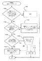
図11は、接続が開始された(例えば、接続メソッドが始動されたとき)ときの調和ステップを示す。ステップ1100では、接続によって特定されたデバイスインスタンスGUIDは、各々のデバイスがシステムの中で現在、動作中であるか確かめるためにチェックされる。そうであるならば、ステップ1102に分岐し、接続され、その後調和プロセスは終了する。そうでなければ、ステップ1100からステップ1104に分岐して、システム上の他のデバイスが、接続オブジェクトの中に示された媒体の型に適合するか否かを判断するためにチェックされる。もし適合しないならば、ステップ1106は、適合するエラーメッセージを出し、プロセスを終了する(後述のユーザー承認など)。
【0052】
しかし、ステップ1104でデバイスが適合すれば、2以上の動作デバイスが、接続オブジェクトの中に示された媒体の型に適合するか否か判断するためのステップ1108が実行される。そうであるならば、ステップ1110は、どのデバイスを使用するかユーザーに要求する。ユーザーは、デバイスを選択するか、接続をキャンセル(ステップ1114で、接続が中断される)することができる。ユーザー選択によって、または唯一適合するデバイスが存在するとき、唯一特定されたデバイスは媒体の型に適合するので、ステップ1112では、接続におけるデバイスは適合するデバイスにリセットされ、接続を行う。
【0053】
図12は、システムがLANに接続され、接続が要求されたときに実行されるネットワーク調和プロセスを示す。ステップ1200では、LANアダプタに接続するための2以上の接続オブジェクトが特定されているか判断するためチェックされる。特定されなければ、ステップ1200からステップ1208へ分岐し、接続されたLANアダプタに特定された一つの接続オブジェクトが活性化される。
【0054】
しかし、2以上のアダプタが特定されると、ステップ1200からステップ1202に分岐し、提供されたとき、自動的にLANアダプタに接続する2以上の接続オブジェクトを見つける。自動接続に対して唯一の接続オブジェクトが特定されているか、ステップ1204で判断され、ステップ1208で接続オブジェクトが活性化される。一方、ステップ1204で2以上であれば、ステップ1206は、どの接続オブジェクトを使用するかユーザーに要求する。ユーザーが一つを選択すると、ステップ1208で接続オブジェクトが活性化され、他方ユーザーがキャンセルすると、ステップ1210で接続は中断される。
【0055】
最後に、本発明は、動的ネットワークコンポーネントバインディングを提供する。これは、動作中のネットワークコンポーネントおよびその構成を、システムスタート後に再構成する能力を提供する。これは、接続オブジェクトおよびそれに対応するネットワーク構成を、コンピュータの再スタートを必要とせず柔軟に様々な組み合わせに適用する能力によってなされる。この結果、動作構成に適用するために接続オブジェクトが選択されたとき、動的ネットワークコンポーネントバインディングプロセス98は、選択された接続オブジェクトに示された様々なコンポーネントを通し、これらコンポーネントがシステムで利用可能であるか否かを見つける。例えば、特定のネットカードが定義されているとき、プロセスは、そのカード(または両立性のあるカード)がシステム上に存在するか否かをチェックする。同様に、プロトコルおよび/またはクライアントソフトウェアのインスタンスが定義されたとき、プロセスは、そのインスタンスがロードされるか否かを決定し、それをロードして(可能であれば)、インスタンスを開始する。また、バインディングは、動的に選択され、コンポーネントに接続する。この方法で、選択された構成は、最小限のユーザー命令で適用することができる。
【0056】
以上詳細な説明で見てきたように、ネットワーク構成を簡単にするシステムおよび方法を提供し、静的なネットワーク構成モデルをコネクション型のネットワークモデルに置きかえる。このシステムおよび方法は、ユーザーに、複雑な手続きを実質的に少くして選択されたネットワークへの接続を構成することを可能にし、異なった方法で異なるネットワーキングメソッドを提供するユーザーインタフェースを提供する。この方法およびシステムは、ユーザーに対し、エラーの機会を少なくしたコンピュータのネットワーク構成の簡単な選択を与え、自動的に特定のコンピュータシステム上で利用できる動作コンポーネントと共に選択された構成オプションの調和を与える。
【0057】
本発明は、様々な変更および代替の構成に適合可能であり、図示された実施例は図中に明らかにされており、詳細は以上に述べた。本発明を開示された特定の内容に限定する意図はなく、さらに本発明は、すべての変更、代替の構成、および本発明の目的および要旨を逸脱することのない同様のものを含むことは理解されるであろう。
【図面の簡単な説明】
【図1】 本発明を組み込むことのできるコンピュータシステムを示すブロック図である。
【図2】 コンピュータをネットワークへ接続する多数の方法の一実施例を示すブロック図である。
【図3】 本発明の一形態に従って構成情報を保存するための接続オブジェクトの概念を表わす図である。
【図4】 本発明の一形態に従ってネットワークへ接続するための構成情報を有する接続オブジェクトを表わす図である。
【図5】 本発明の接続オブジェクト上で動作する種々のコンポーネントを示すブロック図である。
【図6】 接続フォルダを通してユーザーに提供されるユーザーインタフェースを示す図である。
【図7】 属性値シートを通してユーザーから構成情報を受信するためのユーザーインタフェースを示す図である。
【図8】 接続が接続フォルダに転送された時に生じる調和プロセスを示すフロー図である。
【図9】 システムデバイスが削除または消去されたことを検出した時に生じる調和プロセスを示すフロー図である。
【図10】 システムデバイスがイネーブルまたはインストールされたことを検出した時に生じる調和プロセスを示すフロー図である。
【図11】 接続が動作するのに先だって生じる調和プロセスを示すフロー図である。
【図12】 2以上の接続オブジェクトが取り付けられたLANアダプタを規定する時に生じる調和プロセスを示すフロー図である。[0001]
(Technical field)
The present invention relates generally to computers and computer networks, and more particularly to an improved method and system for connecting a computer to a computer network.
[0002]
(Background of the Invention)
Computer user interaction with networks is on the rise. However, setting up a computer to connect to a network is a task that can be daunting. In order to set up a connection, the user now needs to work with a highly technical user interface that requires the user to understand the networking implementation model. In general, in order to configure a computer for networking, computer users must manually modify network configuration options individually, typically installing protocol stack attribute values for networking components, Binding and setting. At the same time, implementations such as "adapter", "protocol", "service", and "binding" do not inform the user what the purpose they provide, so it is usually incomprehensible or extremely extreme for the average user. It is a scary thing.
[0003]
Nevertheless, in order to properly configure the computer to connect to the network, the user must select the correct option for each, and that correct option sometimes depends on the settings of the other options May change. For example, using a special type of client software may require a special protocol. As a result, manually configuring network parameters directly is prone to a significant number of user errors, and the number of support calls to assist with network configuration is long and protracted.
[0004]
Furthermore, computer networking currently assumes a static network configuration, i.e. once established, it will not change thereafter. However, this model has its inherent disadvantages. The reason is that computers are increasingly required to interact with the network variously based on network configuration changes, computer placement changes, user request changes, and the like. For example, a user may connect to a local area network (LAN) at the office and connect to a wide area network (WAN) at home. If the same physical computer is used in both locations, the user will need to reconfigure the computer each time the other type of connection is made. Even without physically using the same computer, the user is provided with an independent and unique user interface for each connection, and also handles already difficult configuration processes.
[0005]
(Object and Summary of Invention)
Accordingly, it is an object of the present invention to provide a method and system for simplifying network configuration.
[0006]
In achieving this goal, replacing a static network configuration model with a connection-oriented networking model is a related goal.
[0007]
Another object is to provide a method and system characterized above that allows a user to configure a connection to a selected network substantially without complicated procedures.
[0008]
Yet another object is to provide a user interface that provides different networking methods in different ways.
[0009]
Yet another object is to provide a method and system that allows a user to easily change the network configuration of a computer with fewer opportunities for errors.
[0010]
Another object is to provide a method and system that automatically reconciles selected configuration options with the actual components available on a particular computer system.
[0011]
That is, the present invention provides a method and system for configuring a computer to connect to different networks. In order to receive input from the user, a user interface is provided, and the network and its configuration information are identified by the input. Configuration information can be stored individually in a file in the file system for each network connection, for example by writing information into a data structure stored in a non-volatile storage device. And stored independently for each different network.
[0012]
To connect the computer to the selected network, the configuration information is retrieved from the data structure corresponding to the selected network, and the connection is made by applying the retrieved information and parameters to the operating configuration of the system . A process is provided to reconcile network components described by connection objects with network components that are actually provided on the computer system.
[0013]
Other objects and advantages will become apparent from the following detailed description in conjunction with the figures.
[0014]
(Detailed Description of Preferred Embodiment)
(Typical execution environment)
FIG. 1 and the following discussion are intended to provide a brief general purpose of a suitable computing environment in which the invention may be implemented. Although not required, the invention will be described in the context of computer-executable instructions, such as program modules, being executed by a personal computer. Generally, program modules include routines, programs, objects, components, data structures, etc. that perform particular tasks or perform particular abstract data types. Furthermore, it will be apparent to those skilled in the art that the present invention may be practiced in other computer system configurations including handheld devices, multiprocessor systems, microprocessor-type or programmable consumer electronics, network PCs, minicomputers, mainframe computers, and the like. It is. The invention may also be practiced in distributed computing environments where tasks are performed by remote computing devices that are linked through a communications network. In a distributed computing environment, program modules can be located in both local and remote storage devices.
[0015]
Referring to FIG. 1, a typical system for implementing the present invention includes a general purpose computer device in the form of a conventional
[0016]
A number of program modules can be stored in the hard disk,
[0017]
The
[0018]
When using a LAN networking environment, the
[0019]
FIG. 2 illustrates some of the ways in which a computer can connect to
[0020]
In addition,
[0021]
In connection with one aspect of the present invention, instead of changing the network settings, as conceptually shown in FIG. 3, the user can connect to networking components (eg, devices, protocols) corresponding to connections to other computers. , Binding information, etc.), for example, for each network connection, a connection object 76 1 -76 n Is generated. In general, connection objects provide links that support functionality between the user's computer and other entities. For example, each connection object 76 1 -76 n Contains an independent description of the networking configuration that requires connection to a particular network. For example, connection object 76 1 Identifies
[0022]
As shown in FIG. 4, various networking information can be obtained from the user interface. For example, a user interface provided as a
[0023]
[Table 1]
Other methods of obtaining configuration information for a particular network, with the addition of wizards and attribute value sheets, are feasible and can be used. Regardless of how the information is obtained, the connection object contains information that associates a particular user connection with a particular network. For example, as shown in FIG. 2 Identifies that the connection is reliably used with the
[0025]
Connection object 76 1 -76 n Preferably includes a data structure having methods and data encapsulated therein. Basic methods common to connection objects include connecting to the network via the object's configuration information, or disconnecting if connected. In order to connect to the network, the adapted configuration information is applied to the operating configuration of the system described below.
[0026]
Five object classes are already defined. Includes LAN, dial-up, direct connection, virtual private network and inbound classes. A virtual private network is applied to a secure connection to a private network through a public network such as the Internet. As an important advantage, additional methods can include rules for each class of object, and the object can hide many of the often confusing settings from the user. For example, the
[0027]
In connection with one aspect of the present invention, since multiple connection objects exist independently on the system, each connection object is unique in a network configuration independent of several current operating configurations. Keep the element. As a result, when the user wants to change the network configuration, the user can select a new connection object or change the attribute values of other connection objects and apply that connection object to the current operating configuration. can do. As is well known (eg, in Windows NT and Windows 95 compliant systems), there is an operational configuration in the registration of the system that corresponds to any network component information. Therefore, within the scope of the present invention, in order to connect to other networks, the component and parameter information of the connection object is applied to the operational configuration by writing information in its registration. Usually, the computer does not need to be restarted to change the network configuration.
[0028]
Further, the connection object information can be stored in a nonvolatile storage device (for example, the
[0029]
As shown in FIG. 5, to simplify the use of the connection object, the
[0030]
In summary, to perform networking configuration for each network, the user modifies
[0031]
In connection with another aspect of the present invention, each connection object 76. 1 -76 n Provides a user interface consisting of different elements regardless of the type of connection (eg WAN or LAN). This allows the object to adopt connections consisting of different elements as user interface objects that act as proxies and input points for these basic connection methods. Connections allow connection objects to be stored, accessed, manipulated, transferred, created and destroyed in the same way, regardless of the type of networking they support.
[0032]
Similarly, there are further identified connection object classes to handle functional and user interface requests. Each connection object supports the same set of basic methods, adapts to the same transfer model (eg, file transfer), and shares its attribute value as a reliable attribute.
[0033]
For example, each connection in the system has a corresponding connection object in the connection folder. The connection object is the first user input point in the configuration attribute value and method for each connection. As shown in the
[0034]
The connection object provides an “options” tab in its
[0035]
If the connection needs to touch some technical attribute values such as protocol configuration, encryption, authentication, etc., the “Extended” tab provides a consistent means between the connection interfaces. The “Extended” tab shows where the protocol configuration exists like other network stack configurations.
[0036]
Finally, the “Authorization” tab gives the administrator or power user the ability to specify the user's rights for the connection, while managing the integrity of the connection.
[0037]
Within the scope of the present invention, a function is provided that automatically reconciles the stored information with the active device or connection objects associated with multiple devices available on a given device. In general, the goal of harmonizing devices is to maintain device references that are stored simultaneously based on user requirements, independent of the device.
[0038]
As an example, a large number of computers managed by a system administrator can be connected to a LAN adapter 53, and the administrator can request that a corresponding connection object using that adapter 53 be deployed. At the same time, when a particular system uses another connection of the LAN adapter instead, it will automatically try another connection by harmony.
[0039]
To achieve harmony, the system utilizes globally unique identifiers (GUIDs). As is well known, the GUID is a 128-bit integer value that is used to specify a globally unique identifier for the COM interface and coclass. GUIDs are mapped to instances of the GUID class.
[0040]
For reconciliation, the system provides a reconciliation process 92 (FIG. 5) that parses the device instance GUID, and the device media type is preserved when the connection is applied. Saving GUIDs for the devices used in the connection ensures that the connection is activated at the next opportunity, and its operation is the same unless the device hardware is changed on the system. This also ensures that any harmonized procedure requires an activated connection, regardless of whether user interaction is required, and that a given hardware configuration is executed only once. .
[0041]
Preserving the media type allows the system to target devices that are likely to be compatible with the connection configuration, even if the devices have different connections or have different capabilities. Examples of media types include Ethernet, Fast Ethernet token ring, FDDI, ATM, ISDN, modem, serial port and parallel port.
[0042]
In general, two stages of harmony are provided to accomplish two distinct purposes. The first purpose is to indicate when a connection is not available as a result of a system shortage of compatible devices. The second purpose is to reset the device related to the connection after determining that the original device of the connection is not available.
[0043]
When compatible devices are not available, as a result such devices are either removed from the system or installed, and their non-usefulness can be attributed to the user through a connection folder, taskbar or user interface where the connection is not available. Detected to show. For example, when networking devices are present in a user's docking station, and when a portable computer is not docked (and when there are no other compatible devices useful), connection objects are unavailable to them It is shown that.
[0044]
Instead, when the original device of the connection is not provided, but there is a compatible device, harmony provides the newly detected device with the possibility of resetting the device specified by the connection. For example, when a user replaces a modem or LAN card in a computer, any connection that references the original device provides a reference to the newly available device for resetting the original reference. As another example, when a system administrator deploys a connection object and uses it on multiple systems, the connection object is associated with the distributed connection object in the end-user system against a device reset associated with the distributed connection object. Provide a device to do.
[0045]
One event that causes harmony is when a connection object exists in the
[0046]
FIG. 8 shows the general steps by the
[0047]
However, if the device instance GUID does not exist on the device,
[0048]
FIG. 9 shows the general steps by the
[0049]
However, if the connection uses an instance GUID, branching from
[0050]
FIG. 10 shows the general steps by the
[0051]
FIG. 11 shows the reconciliation steps when a connection is initiated (eg, when a connection method is initiated). In
[0052]
However, if the devices are matched in
[0053]
FIG. 12 shows a network coordination process that is performed when the system is connected to a LAN and a connection is requested. In
[0054]
However, if two or more adapters are identified, the process branches from
[0055]
Finally, the present invention provides dynamic network component binding. This provides the ability to reconfigure operating network components and their configuration after system start. This is done by the ability to flexibly apply the connection object and its corresponding network configuration to various combinations without requiring a computer restart. As a result, when a connection object is selected to apply to the operational configuration, the dynamic network
[0056]
As has been seen in the foregoing detailed description, a system and method that simplifies network configuration is provided, replacing a static network configuration model with a connection-type network model. This system and method provides a user interface that allows a user to configure a connection to a selected network with substantially fewer complex procedures and provides different networking methods in different ways. This method and system provides the user with a simple selection of computer network configurations with reduced chances of error and automatically reconciles selected configuration options with operational components available on a particular computer system. .
[0057]
The present invention is adaptable to various modifications and alternative configurations, and the illustrated embodiments are disclosed in the drawings, and the details have been described above. It is to be understood that the invention is not intended to be limited to the particular content disclosed, and that the invention includes all modifications, alternative constructions, and the like without departing from the purpose and spirit of the invention. Will be done.
[Brief description of the drawings]
FIG. 1 is a block diagram that illustrates a computer system into which the present invention may be incorporated.
FIG. 2 is a block diagram illustrating one embodiment of a number of methods for connecting a computer to a network.
FIG. 3 is a diagram representing a concept of a connection object for storing configuration information according to an embodiment of the present invention.
FIG. 4 is a diagram representing a connection object having configuration information for connecting to a network in accordance with an aspect of the present invention.
FIG. 5 is a block diagram illustrating various components that operate on a connection object of the present invention.
FIG. 6 is a diagram illustrating a user interface provided to a user through a connection folder.
FIG. 7 is a diagram illustrating a user interface for receiving configuration information from a user through an attribute value sheet.
FIG. 8 is a flow diagram illustrating a reconciliation process that occurs when a connection is transferred to a connection folder.
FIG. 9 is a flow diagram illustrating a reconciliation process that occurs when it detects that a system device has been deleted or erased.
FIG. 10 is a flow diagram illustrating a reconciliation process that occurs when it detects that a system device has been enabled or installed.
FIG. 11 is a flow diagram showing a reconciliation process that occurs prior to connection operation.
FIG. 12 is a flow diagram illustrating a harmonization process that occurs when defining a LAN adapter with two or more connection objects attached thereto.
Claims (5)
前記異なるネットワークの各々についての構成情報を獲得するステップであって、該構成情報は、該ネットワークの各々に対する接続から独立して獲得され、該ネットワークへの接続のために動作するデバイス媒体の型と、デバイスを一意に識別する識別子とを識別する、構成情報を獲得するステップと、
前記ネットワークの各々に対する構成情報をデータ構造に維持するステップであって、該データ構造は、他のネットワークと関連付けられた他のデータ構造とは独立するオブジェクトであり、メソッドおよびデータをその中に含む、データ構造に維持するステップと、
前記ネットワークの特定の一つに接続するためにユーザーからの要求を受信するステップと、
前記要求に基づいて当該ネットワークに対する前記データ構造に維持される構成情報を検索するステップと、
前記構成情報を前記システムにおいてイネーブルされたデバイスと調和させるステップであって、
該調和させるステップは、
前記検索した構成情報に、前記ユーザーから要求されるデバイスを示す前記識別子が含まれているかを判定するステップと、
前記識別子が含まれていない場合に、前記デバイス媒体の型に基づいて前記システムの中の両立性のあるデバイスを捜し出して、該デバイスを前記接続に利用可能なデバイスとして選択するステップと
を含む、調和させるステップと、
その検索され、かつ調和された構成情報に基づいてネットワーク接続パラメータの値をセットするステップであって、前記オブジェクトの少なくとも1つのメソッドを実行するステップを含み、
前記パラメータ値を介してネットワークに接続するステップと
を実行させることを特徴とする方法。In a method of connecting a computer to one of a plurality of different networks, the computer includes:
Obtaining configuration information for each of the different networks, wherein the configuration information is obtained independently of the connection to each of the networks, and the type of device medium that operates for connection to the network ; Obtaining configuration information that identifies an identifier that uniquely identifies the device ;
A step of maintaining the configuration information for each of the network to the data structure, 該De chromatography data structure is an object that independently of the other data structures associated with the other networks, among them the methods and data a step comprising, maintaining a data structure,
Receiving a request from a user to connect to a particular one of the networks;
Retrieving configuration information maintained in the data structure for the network based on the request ;
Reconciling the configuration information with devices enabled in the system, comprising:
The step of harmonizing comprises
Determining whether the retrieved configuration information includes the identifier indicating a device requested by the user;
Searching for a compatible device in the system based on the type of the device medium if the identifier is not included, and selecting the device as an available device for the connection;
Including harmonizing steps,
Setting a value of a network connection parameter based on the retrieved and harmonized configuration information, comprising executing at least one method of the object;
And connecting to a network via the parameter value.
デバイスアダプタを含むデバイス媒体の型およびプロトコルを示すデータを含むことを特徴とする請求項1に記載の方法。The configuration information is
The method of claim 1 , including data indicating a type and protocol of a device medium that includes a device adapter.
前記システムの中に新しくイネーブルされたまたはインストールされたデバイスを検出するステップを含むことを特徴とする請求項2に記載の方法。The step of harmonizing comprises
The method of claim 2 , comprising detecting a newly enabled or installed device in the system.
前記異なるネットワークの各々についての構成情報であって、前記構成情報は、ネットワークへの接続のために動作するデバイス媒体の型と、デバイスを一意に識別する識別子とを示す情報であるデバイス情報を含み、ネットワークの各々への接続から独立して獲得される構成情報を獲得するためのユーザーインタフェースと、
不揮発性記憶装置と、
各々のネットワークに対する前記構成情報をメソッドおよびデータを含むオブジェクトであって、他のネットワークと関連付けられた他のデータ構造とは独立するオブジェクトとして前記不揮発性記憶装置に記憶されるデータ構造にストアする手段であって、前記ネットワークの内の一つに対する構成情報を他のいずれのネットワークの構成情報からも独立して前記オブジェクトのメソッドを介して検索することができるようにした手段と、
選択ネットワークとしてネットワークを選択する手段と、
その選択ネットワークに対するストアされた構成情報を検索する手段と、
前記構成情報を前記システムの中のデバイスと調和する手段であって、
前記調和する手段は、
前記検索した構成情報に、前記ユーザーから要求されるデバイスを示す前記識別子が含まれているかを判定する手段と、
前記識別子が含まれていない場合に、前記デバイス媒体の型に基づいて前記システムの中の両立性のあるデバイスを捜し出して、該デバイスを前記接続に利用可能なデバイスとして選択する手段と
を含む、調和する手段と、
前記調和された構成情報を適用して前記コンピュータシステムを前記選択ネットワークへ接続する前記オブジェクトの中の少なくとも1つのメソッドと
を備えたことを特徴とするシステム。In a system constituting a computer system for connecting a computer to a plurality of different networks,
Configuration information for each of the different networks, the configuration information including device information that is information indicating a type of device medium that operates for connection to the network and an identifier that uniquely identifies the device. A user interface for obtaining configuration information obtained independently of connection to each of the networks;
A non-volatile storage device;
Means for storing said configuration information for each network in a data structure stored in said non-volatile storage device as an object comprising methods and data, independent of other data structures associated with other networks Means for allowing configuration information for one of the networks to be retrieved via the method of the object independently of configuration information of any other network;
Means for selecting a network as the selected network;
Means for retrieving stored configuration information for the selected network;
Means for harmonizing the configuration information with devices in the system,
The means for harmonizing is
Means for determining whether the retrieved configuration information includes the identifier indicating a device requested by the user;
Means for locating a compatible device in the system based on the type of the device media and selecting the device as an available device for the connection if the identifier is not included;
Means to harmonize, including
At least one method in the object for applying the harmonized configuration information to connect the computer system to the selected network.
Applications Claiming Priority (3)
| Application Number | Priority Date | Filing Date | Title |
|---|---|---|---|
| US08/972,666 US6295556B1 (en) | 1997-11-18 | 1997-11-18 | Method and system for configuring computers to connect to networks using network connection objects |
| US08/972,666 | 1997-11-18 | ||
| PCT/US1998/024432 WO1999026147A2 (en) | 1997-11-18 | 1998-11-16 | Method and system for configuring computers to connect to networks using network connection objects |
Publications (2)
| Publication Number | Publication Date |
|---|---|
| JP2001523859A JP2001523859A (en) | 2001-11-27 |
| JP4647096B2 true JP4647096B2 (en) | 2011-03-09 |
Family
ID=25519977
Family Applications (1)
| Application Number | Title | Priority Date | Filing Date |
|---|---|---|---|
| JP2000521445A Expired - Lifetime JP4647096B2 (en) | 1997-11-18 | 1998-11-16 | Method and system for configuring a computer to connect to a network using a network connection object |
Country Status (6)
| Country | Link |
|---|---|
| US (1) | US6295556B1 (en) |
| EP (1) | EP1032875B1 (en) |
| JP (1) | JP4647096B2 (en) |
| AT (1) | ATE204659T1 (en) |
| DE (1) | DE69801449T2 (en) |
| WO (1) | WO1999026147A2 (en) |
Families Citing this family (45)
| Publication number | Priority date | Publication date | Assignee | Title |
|---|---|---|---|---|
| US6556875B1 (en) * | 1998-06-30 | 2003-04-29 | Seiko Epson Corporation | Device control system |
| US6449642B2 (en) * | 1998-09-15 | 2002-09-10 | Microsoft Corporation | Method and system for integrating a client computer into a computer network |
| US6609153B1 (en) | 1998-12-24 | 2003-08-19 | Redback Networks Inc. | Domain isolation through virtual network machines |
| US6493751B1 (en) * | 1999-02-24 | 2002-12-10 | 3Com Corporation | Network configuration method and system for a window-based operating system environment |
| US6961762B1 (en) * | 2000-02-14 | 2005-11-01 | Sygate Technologies, Inc. | Automatic switching network points based on configuration profiles |
| US6675308B1 (en) * | 2000-05-09 | 2004-01-06 | 3Com Corporation | Methods of determining whether a network interface card entry within the system registry pertains to physical hardware or to a virtual device |
| US7103661B2 (en) * | 2000-07-12 | 2006-09-05 | John Raymond Klein | Auto configuration of portable computers for use in wireless local area networks |
| US20020040434A1 (en) * | 2000-09-12 | 2002-04-04 | Keith Elliston | Techniques for providing and obtaining research and development information technology on remote computing resources |
| US7366769B2 (en) * | 2000-10-02 | 2008-04-29 | Schlumberger Technology Corporation | System, method and computer program product for a universal communication connector |
| FR2815494B1 (en) * | 2000-10-12 | 2003-01-10 | Schneider Automation S A | METHOD FOR CONFIGURING AN AUTOMATION MODULE ON A TCP / IP NETWORK |
| JP2002158732A (en) * | 2000-11-17 | 2002-05-31 | Toshiba Corp | Changeover control system and changeover control method for communication unit |
| JP2002197051A (en) * | 2000-12-11 | 2002-07-12 | Internatl Business Mach Corp <Ibm> | Selection method for communication adapter for determining communication destination, setting method for communication adapter, computer system, portable information device, and storage medium |
| US20020161921A1 (en) * | 2001-04-27 | 2002-10-31 | Docomo Communications Laboratories Usa, Inc. | Method of selecting a network access measure from multiple access measures |
| US7827292B2 (en) * | 2001-07-23 | 2010-11-02 | At&T Intellectual Property Ii, L.P. | Flexible automated connection to virtual private networks |
| US7827278B2 (en) * | 2001-07-23 | 2010-11-02 | At&T Intellectual Property Ii, L.P. | System for automated connection to virtual private networks related applications |
| US8239531B1 (en) | 2001-07-23 | 2012-08-07 | At&T Intellectual Property Ii, L.P. | Method and apparatus for connection to virtual private networks for secure transactions |
| US8001594B2 (en) * | 2001-07-30 | 2011-08-16 | Ipass, Inc. | Monitoring computer network security enforcement |
| US20030061341A1 (en) * | 2001-09-26 | 2003-03-27 | Infineon Technologies North America Corp. | Media cross conversion interface |
| US20030069947A1 (en) * | 2001-10-05 | 2003-04-10 | Lipinski Gregory J. | System and methods for network detection and configuration |
| US20030109509A1 (en) * | 2001-10-11 | 2003-06-12 | Alcon, Inc. | Methods for treating dry eye |
| WO2003034660A1 (en) | 2001-10-16 | 2003-04-24 | Sony Corporation | Communication system and method, information processing apparatus and method, and information processing terminal and method |
| JP3588604B2 (en) * | 2001-11-30 | 2004-11-17 | 株式会社東芝 | Electronic device and communication device switching method |
| US7451222B2 (en) * | 2002-02-13 | 2008-11-11 | Gateway Inc. | Client-centered WEP settings on a LAN |
| US7093018B1 (en) | 2002-03-06 | 2006-08-15 | Novell, Inc. | Methods, systems, and data structures to connect services |
| US20030217126A1 (en) * | 2002-05-14 | 2003-11-20 | Polcha Andrew J. | System and method for automatically configuring remote computer |
| AU2003239319A1 (en) * | 2002-05-14 | 2003-12-02 | Andrew J. Polcha | System and method for automatically configuring remote computer |
| US20030236865A1 (en) * | 2002-06-20 | 2003-12-25 | Microsoft Corporation | Method and system for configuring remote access to a server |
| US6754346B2 (en) | 2002-07-31 | 2004-06-22 | Steven P. Eiserling | Method for tracing the distribution of physical digital media |
| US6813531B2 (en) | 2002-09-20 | 2004-11-02 | International Business Machines Corporation | Method, system, and article of manufacture for product configuration |
| AU2003297433A1 (en) * | 2002-12-24 | 2004-07-22 | Samrat Vasisht | Method, system and device for automatically configuring a communications network |
| US8533597B2 (en) * | 2003-09-30 | 2013-09-10 | Microsoft Corporation | Strategies for configuring media processing functionality using a hierarchical ordering of control parameters |
| US7552450B1 (en) | 2003-09-30 | 2009-06-23 | Microsoft Corporation | Systems and methods for enabling applications via an application programming interface (API) to interface with and configure digital media components |
| US7287076B2 (en) * | 2003-12-29 | 2007-10-23 | Microsoft Corporation | Performing threshold based connection status responses |
| US20050198302A1 (en) * | 2003-12-29 | 2005-09-08 | Microsoft Corporation | Multi-client support |
| US20050193104A1 (en) * | 2004-02-27 | 2005-09-01 | Wyse Technology Inc. | User interface for remote computing devices |
| US7804783B2 (en) * | 2004-12-23 | 2010-09-28 | David Jones | Automatic detection and testing of new networking connections |
| US7784065B2 (en) * | 2005-02-07 | 2010-08-24 | Microsoft Corporation | Interface for consistent program interaction with auxiliary computing devices |
| US7552202B2 (en) * | 2005-03-10 | 2009-06-23 | International Business Machines Corporation | System and method to uniquely identify identically configured branches in a distributed enterprise |
| US20060224704A1 (en) * | 2005-04-01 | 2006-10-05 | Vijay Parikh | Auto-configuration for data collection terminals |
| US20060277275A1 (en) * | 2005-04-02 | 2006-12-07 | Glaenzer Eric F | Dynamic management of communication ports, devices, and logical connections |
| US8724484B2 (en) | 2005-09-16 | 2014-05-13 | Microsoft Corporation | Connecting to different network types through a common user interface |
| KR20080054158A (en) * | 2006-12-12 | 2008-06-17 | 삼성전자주식회사 | Image forming apparatus and control method thereof |
| EP2140612A2 (en) * | 2007-04-13 | 2010-01-06 | Thomson Licensing | System software productization framework |
| CN102143141B (en) * | 2010-01-29 | 2013-11-27 | 国基电子(上海)有限公司 | Cable modem and method for automatically obtaining country code |
| US10585673B2 (en) * | 2015-02-10 | 2020-03-10 | Hewlett Packard Enterprise Development Lp | Chipset reconfiguration based on device detection |
Family Cites Families (7)
| Publication number | Priority date | Publication date | Assignee | Title |
|---|---|---|---|---|
| US4942540A (en) | 1987-03-02 | 1990-07-17 | Wang Laboratories, Inc. | Method an apparatus for specification of communication parameters |
| WO1995017064A1 (en) | 1993-12-17 | 1995-06-22 | Taligent, Inc. | Object-oriented distributed communications directory service |
| US5557748A (en) * | 1995-02-03 | 1996-09-17 | Intel Corporation | Dynamic network configuration |
| US5838907A (en) * | 1996-02-20 | 1998-11-17 | Compaq Computer Corporation | Configuration manager for network devices and an associated method for providing configuration information thereto |
| US6477581B1 (en) | 1996-04-09 | 2002-11-05 | International Business Machines Corporation | Location/motion sensitive computer connection |
| US6026410A (en) * | 1997-02-10 | 2000-02-15 | Actioneer, Inc. | Information organization and collaboration tool for processing notes and action requests in computer systems |
| US6003068A (en) * | 1997-02-14 | 1999-12-14 | Electronic Data Systems Corporation | Method and apparatus for portably providing shared removable resources to a plurality of computing devices |
-
1997
- 1997-11-18 US US08/972,666 patent/US6295556B1/en not_active Expired - Lifetime
-
1998
- 1998-11-16 AT AT98959467T patent/ATE204659T1/en not_active IP Right Cessation
- 1998-11-16 DE DE69801449T patent/DE69801449T2/en not_active Expired - Lifetime
- 1998-11-16 WO PCT/US1998/024432 patent/WO1999026147A2/en active IP Right Grant
- 1998-11-16 EP EP98959467A patent/EP1032875B1/en not_active Expired - Lifetime
- 1998-11-16 JP JP2000521445A patent/JP4647096B2/en not_active Expired - Lifetime
Also Published As
| Publication number | Publication date |
|---|---|
| EP1032875A2 (en) | 2000-09-06 |
| DE69801449T2 (en) | 2001-12-06 |
| EP1032875B1 (en) | 2001-08-22 |
| WO1999026147A3 (en) | 1999-07-29 |
| US6295556B1 (en) | 2001-09-25 |
| WO1999026147A2 (en) | 1999-05-27 |
| ATE204659T1 (en) | 2001-09-15 |
| JP2001523859A (en) | 2001-11-27 |
| DE69801449D1 (en) | 2001-09-27 |
Similar Documents
| Publication | Publication Date | Title |
|---|---|---|
| JP4647096B2 (en) | Method and system for configuring a computer to connect to a network using a network connection object | |
| US6175918B1 (en) | Client computer, initialization processing method applied to client computer, and computer program product used in client computer | |
| US9075680B2 (en) | Firmware upgrade for thin clients using one or more servers | |
| US9164749B2 (en) | Differential software provisioning on virtual machines having different configurations | |
| US6493751B1 (en) | Network configuration method and system for a window-based operating system environment | |
| US7496739B1 (en) | System and related methods for automatically configuring a computing system | |
| US6108779A (en) | Server and computer network that permit a client to be easily introduced into the computer network | |
| US7024497B1 (en) | Methods for accessing remotely located devices | |
| WO2004025486A2 (en) | Use of off-motherboard resources in a computer system | |
| JPH11511874A (en) | Apparatus and method for providing simple and secure management of a remote server | |
| US20020035591A1 (en) | Information processing apparatus and method | |
| US8973017B2 (en) | Productivity application management | |
| US20060080517A1 (en) | Accessing a protected area of a storage device | |
| US7343560B1 (en) | Method and system for generating dynamic images | |
| EP1385351A1 (en) | Logging mobile devices onto multiple networks | |
| US20050055572A1 (en) | Coordinated network initiator management that avoids security conflicts | |
| Cisco | Preparing to Install CiscoWorks | |
| Cisco | Preparing to Install CiscoWorks | |
| Cisco | Preparing to Install CiscoWorks | |
| Cisco | Preparing to Install CiscoWorks | |
| Cisco | Preparing to Install CiscoWorks | |
| Cisco | Loading System Software Images and Configuration Files | |
| Cisco | Preparing to Install CiscoWorks | |
| Cisco | Preparing to Install CiscoWorks | |
| Cisco | Preparing to Install CiscoWorks |
Legal Events
| Date | Code | Title | Description |
|---|---|---|---|
| A621 | Written request for application examination |
Free format text: JAPANESE INTERMEDIATE CODE: A621 Effective date: 20050518 |
|
| RD04 | Notification of resignation of power of attorney |
Free format text: JAPANESE INTERMEDIATE CODE: A7424 Effective date: 20050518 |
|
| A977 | Report on retrieval |
Free format text: JAPANESE INTERMEDIATE CODE: A971007 Effective date: 20070914 |
|
| A131 | Notification of reasons for refusal |
Free format text: JAPANESE INTERMEDIATE CODE: A131 Effective date: 20070921 |
|
| A601 | Written request for extension of time |
Free format text: JAPANESE INTERMEDIATE CODE: A601 Effective date: 20071220 |
|
| A602 | Written permission of extension of time |
Free format text: JAPANESE INTERMEDIATE CODE: A602 Effective date: 20071228 |
|
| A521 | Request for written amendment filed |
Free format text: JAPANESE INTERMEDIATE CODE: A523 Effective date: 20080321 |
|
| A02 | Decision of refusal |
Free format text: JAPANESE INTERMEDIATE CODE: A02 Effective date: 20080523 |
|
| A521 | Request for written amendment filed |
Free format text: JAPANESE INTERMEDIATE CODE: A523 Effective date: 20080821 |
|
| RD13 | Notification of appointment of power of sub attorney |
Free format text: JAPANESE INTERMEDIATE CODE: A7433 Effective date: 20080826 |
|
| A521 | Request for written amendment filed |
Free format text: JAPANESE INTERMEDIATE CODE: A821 Effective date: 20080826 |
|
| A911 | Transfer to examiner for re-examination before appeal (zenchi) |
Free format text: JAPANESE INTERMEDIATE CODE: A911 Effective date: 20080926 |
|
| A912 | Re-examination (zenchi) completed and case transferred to appeal board |
Free format text: JAPANESE INTERMEDIATE CODE: A912 Effective date: 20081219 |
|
| RD13 | Notification of appointment of power of sub attorney |
Free format text: JAPANESE INTERMEDIATE CODE: A7433 Effective date: 20100614 |
|
| A521 | Request for written amendment filed |
Free format text: JAPANESE INTERMEDIATE CODE: A821 Effective date: 20100614 |
|
| A01 | Written decision to grant a patent or to grant a registration (utility model) |
Free format text: JAPANESE INTERMEDIATE CODE: A01 |
|
| A61 | First payment of annual fees (during grant procedure) |
Free format text: JAPANESE INTERMEDIATE CODE: A61 Effective date: 20101208 |
|
| FPAY | Renewal fee payment (event date is renewal date of database) |
Free format text: PAYMENT UNTIL: 20131217 Year of fee payment: 3 |
|
| R150 | Certificate of patent or registration of utility model |
Free format text: JAPANESE INTERMEDIATE CODE: R150 |
|
| R250 | Receipt of annual fees |
Free format text: JAPANESE INTERMEDIATE CODE: R250 |
|
| R250 | Receipt of annual fees |
Free format text: JAPANESE INTERMEDIATE CODE: R250 |
|
| S111 | Request for change of ownership or part of ownership |
Free format text: JAPANESE INTERMEDIATE CODE: R313113 |
|
| R350 | Written notification of registration of transfer |
Free format text: JAPANESE INTERMEDIATE CODE: R350 |
|
| R250 | Receipt of annual fees |
Free format text: JAPANESE INTERMEDIATE CODE: R250 |
|
| R250 | Receipt of annual fees |
Free format text: JAPANESE INTERMEDIATE CODE: R250 |
|
| R250 | Receipt of annual fees |
Free format text: JAPANESE INTERMEDIATE CODE: R250 |
|
| EXPY | Cancellation because of completion of term |