JP4642489B2 - Imaging apparatus, imaging method, imaging program, and storage medium - Google Patents
Imaging apparatus, imaging method, imaging program, and storage medium Download PDFInfo
- Publication number
- JP4642489B2 JP4642489B2 JP2005016134A JP2005016134A JP4642489B2 JP 4642489 B2 JP4642489 B2 JP 4642489B2 JP 2005016134 A JP2005016134 A JP 2005016134A JP 2005016134 A JP2005016134 A JP 2005016134A JP 4642489 B2 JP4642489 B2 JP 4642489B2
- Authority
- JP
- Japan
- Prior art keywords
- panning
- shutter speed
- correction amount
- imaging
- shake
- Prior art date
- Legal status (The legal status is an assumption and is not a legal conclusion. Google has not performed a legal analysis and makes no representation as to the accuracy of the status listed.)
- Expired - Fee Related
Links
Images


Classifications
-
- G—PHYSICS
- G02—OPTICS
- G02B—OPTICAL ELEMENTS, SYSTEMS OR APPARATUS
- G02B27/00—Optical systems or apparatus not provided for by any of the groups G02B1/00 - G02B26/00, G02B30/00
- G02B27/0025—Optical systems or apparatus not provided for by any of the groups G02B1/00 - G02B26/00, G02B30/00 for optical correction, e.g. distorsion, aberration
- G02B27/0068—Optical systems or apparatus not provided for by any of the groups G02B1/00 - G02B26/00, G02B30/00 for optical correction, e.g. distorsion, aberration having means for controlling the degree of correction, e.g. using phase modulators, movable elements
-
- H—ELECTRICITY
- H04—ELECTRIC COMMUNICATION TECHNIQUE
- H04N—PICTORIAL COMMUNICATION, e.g. TELEVISION
- H04N23/00—Cameras or camera modules comprising electronic image sensors; Control thereof
- H04N23/60—Control of cameras or camera modules
- H04N23/68—Control of cameras or camera modules for stable pick-up of the scene, e.g. compensating for camera body vibrations
- H04N23/682—Vibration or motion blur correction
- H04N23/685—Vibration or motion blur correction performed by mechanical compensation
- H04N23/687—Vibration or motion blur correction performed by mechanical compensation by shifting the lens or sensor position
-
- G—PHYSICS
- G02—OPTICS
- G02B—OPTICAL ELEMENTS, SYSTEMS OR APPARATUS
- G02B27/00—Optical systems or apparatus not provided for by any of the groups G02B1/00 - G02B26/00, G02B30/00
- G02B27/64—Imaging systems using optical elements for stabilisation of the lateral and angular position of the image
- G02B27/646—Imaging systems using optical elements for stabilisation of the lateral and angular position of the image compensating for small deviations, e.g. due to vibration or shake
-
- G—PHYSICS
- G03—PHOTOGRAPHY; CINEMATOGRAPHY; ANALOGOUS TECHNIQUES USING WAVES OTHER THAN OPTICAL WAVES; ELECTROGRAPHY; HOLOGRAPHY
- G03B—APPARATUS OR ARRANGEMENTS FOR TAKING PHOTOGRAPHS OR FOR PROJECTING OR VIEWING THEM; APPARATUS OR ARRANGEMENTS EMPLOYING ANALOGOUS TECHNIQUES USING WAVES OTHER THAN OPTICAL WAVES; ACCESSORIES THEREFOR
- G03B17/00—Details of cameras or camera bodies; Accessories therefor
-
- H—ELECTRICITY
- H04—ELECTRIC COMMUNICATION TECHNIQUE
- H04N—PICTORIAL COMMUNICATION, e.g. TELEVISION
- H04N23/00—Cameras or camera modules comprising electronic image sensors; Control thereof
- H04N23/60—Control of cameras or camera modules
- H04N23/68—Control of cameras or camera modules for stable pick-up of the scene, e.g. compensating for camera body vibrations
- H04N23/681—Motion detection
- H04N23/6815—Motion detection by distinguishing pan or tilt from motion
-
- G—PHYSICS
- G03—PHOTOGRAPHY; CINEMATOGRAPHY; ANALOGOUS TECHNIQUES USING WAVES OTHER THAN OPTICAL WAVES; ELECTROGRAPHY; HOLOGRAPHY
- G03B—APPARATUS OR ARRANGEMENTS FOR TAKING PHOTOGRAPHS OR FOR PROJECTING OR VIEWING THEM; APPARATUS OR ARRANGEMENTS EMPLOYING ANALOGOUS TECHNIQUES USING WAVES OTHER THAN OPTICAL WAVES; ACCESSORIES THEREFOR
- G03B2217/00—Details of cameras or camera bodies; Accessories therefor
- G03B2217/005—Blur detection
Description
本発明は、撮像装置及び撮像方法、並びに撮像プログラム及び記憶媒体に関し、特に、振れ補正機能を備えた撮像装置及び撮像方法、並びに撮像プログラム及び記憶媒体に関する。 The present invention relates to an imaging apparatus, an imaging method, an imaging program, and a storage medium, and more particularly, to an imaging apparatus and an imaging method that have a shake correction function, an imaging program, and a storage medium.
例えば、カメラやビデオカメラ等の撮像装置には、撮像装置が振れ補正機能を発揮するように、光学式の振れ補正装置が搭載されることがある。この振れ補正装置による振れ補正は、撮影レンズの一部であるシフトレンズを撮影レンズの光軸に対して垂直方向に駆動して撮影レンズの光軸を変化させることによって行われる。 For example, an imaging apparatus such as a camera or a video camera may be equipped with an optical shake correction apparatus so that the imaging apparatus exhibits a shake correction function. The shake correction by the shake correction apparatus is performed by driving a shift lens, which is a part of the photographing lens, in a direction perpendicular to the optical axis of the photographing lens to change the optical axis of the photographing lens.
図8は、従来の振れ補正装置が搭載された撮像装置の構成を概略的に示すブロック図である。 FIG. 8 is a block diagram schematically showing a configuration of an imaging apparatus equipped with a conventional shake correction apparatus.
本来、撮像装置の振れ補正は、撮影レンズの光軸に対して垂直の面内において水平方向及び鉛直方向の2方向について行われるが、図8においては、簡略化のために水平方向の振れ補正を行う撮像装置が示されている。 Originally, the shake correction of the imaging apparatus is performed in two directions, ie, the horizontal direction and the vertical direction in a plane perpendicular to the optical axis of the photographing lens. In FIG. An imaging device that performs is shown.
図8において、撮像装置800は、角速度信号(即ち、撮像装置800の振れ)を検出する角速度センサ101と、角速度センサ101からの出力であるドリフト等を除去する高域通過(ハイパス)フィルタ(HPF)102と、角速度センサ101により検出された角速度信号を増幅するアンプ103と、振れ補正、オートフォーカス(AF)、ズーム、及び自動露出(AE)等のカメラ機能についての制御を行うカメラシステム制御マイクロコンピュータ(以下、「マイコン」とする)120と、撮影レンズ(不図示)の一部であるシフトレンズ133と、シフトレンズ133の位置を検出する位置センサ115と、位置センサ115により検出された位置信号を増幅するアンプ116と、シフトレンズ133を撮影レンズの光軸に対して水平方向に駆動するHブリッジドライバ114とを備える。
In FIG. 8, an
マイコン120は、角速度信号をデジタル信号に変換して角速度データにする内蔵A/Dコンバータ104と、この角速度データに対して所定の信号処理を施すHPF105及び位相補償フィルタ106と、後述するパンニング制御用のカットオフ周波数を変更できる可変HPF107と、角度信号を生成して、シフトレンズ113を駆動するための駆動目標値としての補正信号を出力する積分器108と、アンプ116により増幅された出力をデジタル信号に変換して位置データとする内蔵A/Dコンバータ117と、シフトレンズ133の現在位置と駆動目標値との差分を計算して、実際の補正量を出力する加算器111と、Hブリッジドライバ114による駆動の騒音を低減する低域通過フィルタ(LPF)112と、LPF112の出力をPWM変調するPWM変調部113とを備える。
The
マイコン120は、PWM変調部113から出力されたPWMにより、Hブリッジドライバ114を介してシフトレンズ113を駆動して振れ補正を行う。
The
以下、撮像装置800によって実行されるパンニング制御について説明する。
Hereinafter, panning control executed by the
撮影者が撮像装置800の移動を伴う撮影、即ちパンニングを行った場合は、撮影者の意図通りに画が動くことが望ましい。しかし、パンニングを行っている時に通常の振れ補正を行うと、パンニング開始時においては振れ補正が行われるため画が動かないのに対し、補正範囲を超えたときに突然画が動き出すので、画の動きが不連続となり、また、パンニング終了時においては画が補正端に張り付く現象、即ち、端当たり現象が発生し、振れ補正が行えないという不都合があった。斯かる不都合を回避すべく、パンニング制御による補正量が大きくなった時に、DC成分をカットして補正部をセンタリングすることが行われている。
When the photographer performs photographing with panning of the
パンニング制御の一例として、積分器108の出力が予め決められた補正範囲を超えた場合に、低域信号を除去すべく可変HPF107のカットオフ周波数を変更して、振れの補正量を制限すること等が挙げられる。このパンニング制御により、パンニング中の振れ補正信号が中心位置に近い信号となり、上記不都合が解消される。
As an example of panning control, when the output of the
図9は、図8における積分器の出力の大きさの変化に応じたHPFカットオフ周波数(Hz)の値を示す図である。 FIG. 9 is a diagram showing the value of the HPF cutoff frequency (Hz) corresponding to the change in the magnitude of the output of the integrator in FIG.
図9において、折れ線は、積分器108の出力の大きさとHPFカットオフ周波数(Hz)との関係を示す。積分器108の出力が設定値Aを超えた場合は、可変HPF107のカットオフ周波数(Hz)は積分器108の出力が大きくなるにつれて高くなり、また、積分器108の出力が設定値Bを超えた場合は、端当たり現象を防止すべく、さらに急峻にカットオフ周波数が高くなる。
In FIG. 9, the broken line indicates the relationship between the output level of the
上記のように、積分器108の出力の大きさに応じて可変HPF107のカットオフ周波数を変更することにより、パンニング時における振れ補正量に制限を加えて、撮影者の意図通りに画を動かすことができる。
As described above, by changing the cutoff frequency of the
ところで、上記のような振れ補正機能を有する撮像装置によって静止画の撮影を行う場合、ブレの無い画を撮影するためには、抑振効果が高いほど好ましい。ところが、手ブレが発生するとパンニング制御が行われてしまい、結果として抑振効果が悪くなることがある。斯かる抑振効果の悪化を防止すべく、動画撮影時と静止画撮影時とでパンニング制御を変更する方法がある(例えば、特許文献1参照)。さらに、静止画撮影時において、パンニング制御を行わないものがある(例えば、特許文献2参照)。これらの方法により、静止画撮影時の抑振効果を高める試みがなされている。
しかしながら、動画撮影時と静止画撮影時とでパンニング制御を変更する方法では、パンニング制御の制限量によっては、低速シャッタ時に必要な抑振効果が得られず、また、パンニング制御の制限量が少なすぎたり、パンニング制御を全く行わないと、撮影者が意図的に流し撮りを目的としてパンニングを行った時等に、端当たり現象が発生して静止画にブレが生じたり、撮影者の意図通りの構図の画を撮影することができない場合があった。 However, in the method of changing the panning control between the moving image shooting and the still image shooting, depending on the limit amount of the panning control, the necessary suppression effect at the time of the low shutter speed cannot be obtained, and the limit amount of the panning control is small. If the panner does not perform panning control at all, or if the photographer intentionally pans for the purpose of panning, etc., the edge contact phenomenon may occur and blurring may occur in the still image. In some cases, it was not possible to shoot images with the composition.
本発明の目的は、シャッタ速度に応じてパンニング制御を変更することができ、もって撮影状況に適した抑振効果を得ることができる撮像装置及び撮像方法、並びに撮像プログラム及び記憶媒体を提供することにある。 An object of the present invention is to provide an imaging apparatus, an imaging method, an imaging program, and a storage medium that can change the panning control according to the shutter speed and can obtain a suppression effect suitable for the imaging situation. It is in.
上記目的を達成するために、請求項1記載の撮像装置は、パンニング状態であると判別されたときに所定のパンニング制御特性でパンニング制御する撮像装置であって、撮影時におけるシャッタ速度を設定するシャッタ速度設定手段と、前記撮像装置の振れを検出する振れ検出手段と、前記振れに対する補正量を演算する補正量演算手段と、前記補正量に基づいて、シフトレンズを駆動することにより前記振れを補正する振れ補正手段とを備える撮像装置において、前記シャッタ速度設定手段により設定されたシャッタ速度及び前記補正量に基づいて前記撮像装置が前記パンニング状態にあるか否かを判別するパンニング判別手段と、前記設定されたシャッタ速度が遅くなるに従って大きくなるように設定されている閾値を前記補正量が越えるまで前記パンニング判別手段が前記パンニング状態を判別しないように、前記シャッタ速度設定手段により設定されたシャッタ速度及び前記補正量に基づいて前記パンニング制御特性を変更するパンニング制御特性変更手段とを備えることを特徴とする。
To achieve the above object, an imaging apparatus according to
上記目的を達成するために、請求項6記載の撮像方法は、パンニング状態であると判別されたときに所定のパンニング制御特性でパンニング制御する撮像装置の撮像方法であって、撮影時におけるシャッタ速度を設定するシャッタ速度設定ステップと、前記撮像装置の振れを検出する振れ検出ステップと、前記振れに対する補正量を演算する補正量演算ステップと、前記補正量演算ステップで演算された撮像装置の振れ補正量に基づいてシフトレンズを駆動することにより前記振れ検出ステップで検出された撮像装置の振れを補正する振れ補正ステップとを備える撮像方法において、前記シャッタ速度設定ステップで設定されたシャッタ速度及び前記補正量に基づいて前記撮像装置が前記パンニング状態にあるか否かを判別するパンニング判別ステップと、前記設定されたシャッタ速度が遅くなるに従って大きくなるように設定されている閾値を前記補正量が越えるまで前記パンニング判別ステップで前記パンニング状態が判別されないように、前記シャッタ速度設定ステップで設定されたシャッタ速度及び前記補正量に基づいて前記パンニング制御特性を変更するパンニング制御特性変更ステップとを備える。 To achieve the above object, an imaging method according to claim 6, wherein is an imaging method of an imaging device for panning control with a predetermined panning control characteristic when it is determined that the panning state, the shutter in the shooting Kageji a shutter speed setting step of setting a speed, a shake detection step of shake detecting a of the imaging device, prior to the correction amount calculation step of calculating a correction amount for Re Kifu, the correction amount calculation step in the calculated imaging device And a shake correction step of correcting a shake of the imaging device detected in the shake detection step by driving a shift lens based on a shake correction amount of the shutter , and a shutter speed set in the shutter speed setting step and based on the previous Kiho positive amount panning-format to determine whether the imaging apparatus is in the panning state A step, as the by the panning determination step the larger as have been set threshold in accordance with the shutter speed the set is delayed until the correction amount exceeds the panning state is not determined, set by the shutter speed setting step and a panning control characteristic changing step of changing the panning control characteristic based on the shutter speed and the front Kiho positive amount is.
上記目的を達成するために、請求項11記載の撮像プログラムは、パンニング状態であると判別されたときに所定のパンニング制御特性でパンニング制御する撮像装置の撮像方法をコンピュータに実行させる撮像プログラムであって、前記撮像方法が、前記撮像装置の撮影時におけるシャッタ速度を設定するシャッタ速度設定ステップと、前記撮像装置の振れを検出する振れ検出ステップと、前記振れに対する補正量を演算する補正量演算ステップと、前記補正量に基づいて、シフトレンズを駆動することにより前記振れ検出ステップで検出された撮像装置の振れを補正する振れ補正ステップとを備える撮像プログラムにおいて、前記撮像方法は、前記シャッタ速度設定ステップで設定されたシャッタ速度及び前記補正量に基づいて前記撮像装置が前記パンニング状態にあるか否かを判別するパンニング判別ステップと、前記設定されたシャッタ速度が遅くなるに従って大きくなるように設定されている閾値を前記補正量が越えるまで前記パンニング判別ステップで前記パンニング状態が判別されないように、前記シャッタ速度設定ステップで設定されたシャッタ速度及び前記補正量に基づいて前記パンニング制御特性を変更するパンニング制御特性変更ステップとを備えることを特徴とする。 In order to achieve the above object, an imaging program according to claim 11 is an imaging program for causing a computer to execute an imaging method of an imaging apparatus that performs panning control with a predetermined panning control characteristic when it is determined that the camera is in a panning state. Te, the correction amount the imaging method, for calculating a shutter speed setting step of setting a shutter speed, and the shake detection step of detecting a shake of the image pickup apparatus, a correction amount for Re before Kifu at the time of shooting of the imaging device a calculating step, based on the previous Kiho positive amount, in the imaging program and a blur correction step to correct the shake of the detected imaging device by the shake detection step by driving a shift lens, the imaging method, the imaging based on the shutter speed Do及 beauty before Kiho positive amount set by said shutter speed setting step And panning determination step that location is determined whether or not the panning state, the in the panning determination step the larger as have been set threshold in accordance with the shutter speed the set is delayed until the correction amount exceeds as the panning state is not determined, characterized in that it comprises a panning control characteristic changing step of changing the panning control characteristic based on the shutter speed and the front Kiho positive amount set by said shutter speed setting step.
本発明によれば、シャッタ速度に基づいてパンニング状態におけるパンニング制御特性を変更するので、シャッタ速度に応じてパンニング制御を変更することができ、もって撮影状況に適した抑振効果を得ることができる。 According to the present invention, since the panning control characteristic in the panning state is changed based on the shutter speed, the panning control can be changed according to the shutter speed, and thus a vibration suppression effect suitable for the shooting situation can be obtained. .
以下、本発明の実施の形態を図面を参照しながら説明する。 Embodiments of the present invention will be described below with reference to the drawings.
図1は、本発明の実施の形態に係る撮像装置の構成を概略的に示すブロック図である。 FIG. 1 is a block diagram schematically showing a configuration of an imaging apparatus according to an embodiment of the present invention.
図1において、撮像装置100は、レンズユニット130と、レンズユニット130により結像された被写体像を光電変換するCCD135と、CDS(co-related double sampling 相関二重サンプリング)回路、AGC(Automatic Gain Control)回路等から構成され、CCD135で得られた信号に所定の処理を施しアナログ撮像信号を生成するアナログ信号処理部136と、A/D変換器を内蔵し、デジタル信号処理を行った上で最終的な出力映像信号を生成するカメラ信号処理回路137とを備え、これらは直列に接続されている。レンズユニット130は、固定レンズ群131、ズームレンズ群132、シフトレンズ群133、及びフォーカスコンペレンズ群134から成る。
In FIG. 1, an
また、撮像装置100は、角速度信号(即ち、撮像装置の振れ)を検出する角速度センサ101と、角速度センサ101からの出力であるドリフト等を除去する高域通過(ハイパス)フィルタ(HPF)102と、角速度センサ101により検出された角速度信号を増幅するアンプ103と、振れ補正、オートフォーカス(AF)、ズーム、及び自動露出(AE)等のカメラ機能についての制御を行うカメラシステム制御マイクロコンピュータ(マイコン)120とを備え、これらは直列に接続されている。
In addition, the
さらに、撮像装置100は、シフトレンズ群133及び後述するPWM変調部113に接続されたHブリッジドライバ114と、CCD135及び後述するシャッタ制御部121に接続され、CCD135の駆動制御を行うCCD駆動回路138と、シフトレンズ群133の位置を検出する位置センサ115と、位置センサ115及び後述するA/Dコンバータ117に接続されたアンプ116とを備える。
Further, the
マイコン120は、角速度信号をデジタル信号に変換して角速度データにするA/Dコンバータ104と、この角速度データに対して所定の信号処理を施す高域通過フィルタ(HPF)105及び位相補償フィルタ106と、パンニング制御用のカットオフ周波数を変更できる可変高域通過フィルタ(HPF)107と、角度信号を生成して、シフトレンズ113を駆動するための駆動目標値としての補正信号を出力する積分器108とを備え、これらは直列に接続されている。
The
また、マイコン120は、アンプ116により増幅された出力をデジタル信号に変換して位置データにするA/Dコンバータ117と、シフトレンズ群133の現在位置と駆動目標値との差分を計算して、実際の補正量を出力する加算器111と、Hブリッジドライバ114による駆動の騒音を低減する低域通過フィルタ(LPF)112と、LPF112の出力をPWM変調するPWM変調部113とを備え、これらは直列に接続されている。
Further, the
さらに、マイコン120は、可変HPF107及び積分器108に接続され、シャッタ速度に応じてパンニング移行スレッシュを設定し、積分器108から出力された補正信号に基づいて可変HPF107のカットオフ周波数を変更してパンニング制御を行うパンニング制御部122と、パンニング制御部122及びCCD駆動回路138に接続され、カメラ信号処理回路137からの出力された出力映像信号に基づいて最適なシャッタ速度を設定し、CCD駆動回路138を制御すると共にパンニング制御部122に現在のシャッタ速度に関する情報を伝達するシャッタ制御部121とを備える。
Further, the
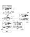
図2は、図1の撮像装置によって実行されるパンニング制御処理の手順を示すフローチャートである。 FIG. 2 is a flowchart illustrating a procedure of panning control processing executed by the imaging apparatus of FIG.
図2において、まず、シャッタ速度の設定値を読み込み(ステップS201)、シャッタ速度が第1の所定速度以上か否かを判定する(ステップS202)。この第1の所定速度は、主としてレンズの焦点距離に基づいて設定され、振れ補正を必要としないシャッタ速度、例えば、レンズの焦点距離が135フィルムカメラ換算で250mmである場合には1/250秒が設定される。 In FIG. 2, first, the shutter speed setting value is read (step S201), and it is determined whether the shutter speed is equal to or higher than a first predetermined speed (step S202). This first predetermined speed is set mainly based on the focal length of the lens and does not require shake correction, for example, 1/250 seconds when the focal length of the lens is 250 mm in terms of 135 film camera. Is set.
シャッタ速度が第1の所定速度以上である場合、すなわちシャッタ速度が第1の所定速度と同じであるか、もしくは速い場合は、パンニング移行スレッシュを最低値に設定し(ステップS203)、通常のパンニング制御特性を設定する(ステップS204)。通常のパンニング制御特性は、図3における折れ線(1)で示される特性であり、補正角度がパンニング移行スレッシュの最低値を超えた時点から可変HPF107のカットオフ周波数が高くなり、さらに補正角度が大きくなるにつれて折れ線(1)の傾きが急峻となり、端当たり現象の防止を行う。なお、図3における縦軸はパンニング制御でのHPFカットオフ周波数設定値を表し、横軸は積分器108の出力に対し、レンズユニット130の焦点距離等を考慮して演算される振れ補正角度(振れ補正量)を表している。
When the shutter speed is equal to or higher than the first predetermined speed, that is, when the shutter speed is the same as or faster than the first predetermined speed, the panning transition threshold is set to the minimum value (step S203), and normal panning is performed. Control characteristics are set (step S204). The normal panning control characteristic is the characteristic indicated by the broken line (1) in FIG. 3, and the cutoff frequency of the
シャッタ速度が第1の所定速度未満である場合、すなわちシャッタ速度が第1の所定速度より遅い場合は、シャッタ速度が第2の所定速度以下か否かを判定する(ステップS205)。第2の所定速度は振れ補正が確実に必要であると推定される低速シャッタ速度、例えば、1/8秒が設定される。 If the shutter speed is less than the first predetermined speed, that is, if the shutter speed is slower than the first predetermined speed, it is determined whether or not the shutter speed is equal to or lower than the second predetermined speed (step S205). The second predetermined speed is set to a low shutter speed, for example, 1/8 second, which is estimated to surely require shake correction.
シャッタ速度が第2の所定速度以下である場合は、パンニング移行スレッシュを最高値に設定し(ステップS206)、パンニング制御特性を低速シャッタ用の設定にする(ステップS207)。これにより、パンニング制御特性は、図3における折れ線(2)で示される特性となる。即ち、パンニング移行スレッシュがほぼ最大補正角(補正端)近傍となり、大きなブレを補正することができる。補正角度がパンニング移行スレッシュの最高値よりも大きくなった場合は、可変HPF107のカットオフ周波数が高くなり、補正端当たりによる誤動作をできる限り見えなくすることができる。さらに、パンニング制御特性を低速シャッタ用の設定にすると、CCD135に長時間(例えば1/8秒間)蓄積された画像の積分効果によって、補正端当たりによる誤動作は見えにくくなる。
If the shutter speed is equal to or lower than the second predetermined speed, the panning transition threshold is set to the maximum value (step S206), and the panning control characteristic is set to the low-speed shutter setting (step S207). As a result, the panning control characteristic is the characteristic indicated by the broken line (2) in FIG. That is, the panning transition threshold is almost in the vicinity of the maximum correction angle (correction end), and a large blur can be corrected. When the correction angle becomes larger than the maximum value of the panning transition threshold, the cut-off frequency of the
シャッタ速度が第2の所定速度より大きい場合は、パンニング移行スレッシュの最高値及び最低値から、シャッタ速度に応じて内挿補間されたパンニング移行スレッシュを演算し(ステップS208)、シャッタ速度に応じたパンニング制御特性が設定される(ステップS209)。このシャッタ速度に応じたパンニング制御特性は、図3における折れ破線(3)で示される折れ線(1)と折れ線(2)との中間の特性になる。 When the shutter speed is higher than the second predetermined speed, the panning transition threshold interpolated according to the shutter speed is calculated from the maximum value and the minimum value of the panning transition threshold (step S208), and the shutter speed is determined. Panning control characteristics are set (step S209). The panning control characteristic according to the shutter speed is an intermediate characteristic between the broken line (1) and the broken line (2) indicated by the broken line (3) in FIG.
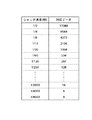
ステップ201にて読み込まれるシャッタ速度は、CCD135における画像蓄積時間の長さに相当する。内挿補間においては演算を簡単にするため、図4のようにシャッタ速度に応じて対応データを設け、パンニング移行スレッシュを高速に演算するようにしている。
The shutter speed read in step 201 corresponds to the length of the image accumulation time in the
図2の処理によれば、シャッタ速度に応じてパンニング制御特性を変更するので(ステップS203〜S204、ステップS206〜S207、およびステップS208〜S209)、手ブレの影響が現れにくい高速シャッタ時はパンニング制御に移行し易くし、手ブレの影響が現れ易い低速シャッタ時はパンニング制御に移行しにくくすることにより、抑振効果を高めることができ、もって撮影状況に適した抑振効果を得ることができる。 According to the processing in FIG. 2, the panning control characteristics are changed according to the shutter speed (steps S203 to S204, steps S206 to S207, and steps S208 to S209). It is possible to increase the suppression effect by making it difficult to shift to panning control at the time of low-speed shutter that makes it easy to shift to control and the effect of camera shake, thereby obtaining a suppression effect suitable for the shooting situation. it can.
図2の処理では、所定速度のシャッタ速度に応じたパンニング移行スレッシュの最低値(ステップS203)、最高値(ステップS206)、及びパンニング制御特性(ステップS204及びステップS207)を予め設定しておき、シャッタ速度に応じたパンニング移行スレッシュ(ステップS208)及びパンニング制御特性(ステップS209)を補間演算によって設定するが、これに限定されるものではなく、例えば、シャッタ速度に応じたパンニング移行スレッシュ及びパンニング制御特性をデータテーブルとしてマイコン内に設定し、この設定されたパンニング移行スレッシュ及びパンニング制御特性をシャッタ速度に応じて読み出すようにする等、シャッタ速度に応じて最適なパンニング制御ができるものであればどのような方法をとってもよい。例えば、図5は、シャッタ速度に応じたパンニング移行スレッシュ及びパンニング制御特性をテーブル化したものである。このテーブルを予めマイコン内に設定しておき、設定されたシャッタ速度に応じてデータを読み込むようにする。シャッタ速度が1/60秒の時のパンニング移行スレッシュ及びパンニング制御特性を図9を用いて説明すると(ただし、横軸は補正角度とみなす)、パンニング移行スレッシュ(A点)は0.14degであり、A点及びB点間の幅が0.09degであり、A点からB点までの折れ線の傾きが0.8であり、B点を超えた場合の折れ線の傾きが2.0となる。このように、マイコン内に設定したテーブルを用いることで、シャッタ速度に応じたパンニング制御特性を持たせることが可能となる。なお、図5においては、第1の所定速度は1/250秒であり、第2の所定速度は1/4秒である。 In the process of FIG. 2, a minimum value (step S203), a maximum value (step S206), and a panning control characteristic (step S204 and step S207) of the panning transition threshold corresponding to a predetermined shutter speed are set in advance. The panning transition threshold (step S208) and the panning control characteristic (step S209) corresponding to the shutter speed are set by interpolation calculation. However, the present invention is not limited to this. For example, the panning transition threshold and panning control corresponding to the shutter speed are set. Set the characteristics in the microcomputer as a data table, and read out the set panning transition threshold and panning control characteristics according to the shutter speed, etc., as long as optimal panning control is possible according to the shutter speed. like It may be in the law. For example, FIG. 5 is a table showing panning transition thresholds and panning control characteristics according to the shutter speed. This table is set in advance in the microcomputer, and data is read according to the set shutter speed. The panning transition threshold and the panning control characteristic when the shutter speed is 1/60 seconds will be described with reference to FIG. 9 (however, the horizontal axis is regarded as the correction angle). The panning transition threshold (point A) is 0.14 deg. The width between the points A and B is 0.09 deg, the inclination of the broken line from the point A to the point B is 0.8, and the inclination of the broken line when the point B is exceeded is 2.0. Thus, by using the table set in the microcomputer, it is possible to have panning control characteristics corresponding to the shutter speed. In FIG. 5, the first predetermined speed is 1/250 seconds, and the second predetermined speed is 1/4 seconds.
図6は、図1の撮像装置の変形例の構成を概略的に示すブロック図である。 FIG. 6 is a block diagram schematically showing a configuration of a modified example of the imaging apparatus of FIG.
図6の撮像装置は、図1の撮像装置と基本的に同じであり、図1の構成と同一の構成には同一の符号を付して重複した説明を省略し、以下に図1の撮像装置と異なる部分についてのみ説明する。 The imaging apparatus in FIG. 6 is basically the same as the imaging apparatus in FIG. 1, and the same components as those in FIG. Only the parts different from the apparatus will be described.
図6において、撮像装置100は、図1の構成に加えてレリーズ手段140を備える。このレリーズ手段140はレリーズスイッチを有し、レリーズスイッチの1段目のスイッチが押された時に図2の処理と同じ動作が行われる。
In FIG. 6, the
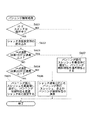
図7は、図6の撮像装置によって実行されるパンニング制御処理の手順を示すフローチャートである。 FIG. 7 is a flowchart illustrating a procedure of panning control processing executed by the imaging apparatus of FIG.
図7において、まず、レリーズスイッチが操作されたかどうかを検出し(ステップS601)、レリーズスイッチ操作がなされていると、シャッタ速度の設定値を読み込み(ステップS602)、シャッタ速度が第1の所定速度以上か否かを判定する(ステップS603)。 In FIG. 7, it is first detected whether or not the release switch has been operated (step S601). If the release switch has been operated, the shutter speed setting value is read (step S602), and the shutter speed is the first predetermined speed. It is determined whether or not this is the case (step S603).
シャッタ速度が第1の所定速度以上である場合は、パンニング移行スレッシュを最低値に設定して通常のパンニング制御特性を設定し(ステップS607)、シャッタ速度が第1の所定速度未満である場合は、シャッタ速度が第2の所定速度以下か否かを判定する(ステップS604)。 When the shutter speed is equal to or higher than the first predetermined speed, the panning transition threshold is set to the lowest value and the normal panning control characteristic is set (step S607). When the shutter speed is lower than the first predetermined speed, Then, it is determined whether or not the shutter speed is equal to or lower than a second predetermined speed (step S604).
シャッタ速度が第2の所定速度以下である場合は、パンニング移行スレッシュを最高値に設定してパンニング制御特性を低速シャッタ用の設定にし(ステップS605)、シャッタ速度が第2の所定速度より大きい場合は、パンニング移行スレッシュの最高値及び最低値から、シャッタ速度に応じて内挿補間されたパンニング移行スレッシュを演算し、シャッタ速度に応じたパンニング制御特性を演算する(ステップS606)。 When the shutter speed is equal to or lower than the second predetermined speed, the panning transition threshold is set to the maximum value and the panning control characteristic is set for the low-speed shutter (step S605), and the shutter speed is higher than the second predetermined speed. Calculates the panning transition threshold interpolated according to the shutter speed from the maximum value and the minimum value of the panning transition threshold, and calculates the panning control characteristic according to the shutter speed (step S606).
また、レリーズスイッチが操作されていない場合は(ステップS601でNO)、パンニング移行スレッシュを最低値に設定して通常のパンニング制御特性を設定する(ステップS607)。 If the release switch is not operated (NO in step S601), the panning transition threshold is set to the lowest value and the normal panning control characteristics are set (step S607).
図7の処理によれば、低速シャッタ時において、レリーズスイッチが操作されるまでは(ステップS601でNO)、パンニング移行が高速シャッタ時と同じように行い(ステップS607)、レリーズスイッチが操作された時にパンニング制御特性を低速シャッタ用に設定する(ステップS605)ので、通常時は低速シャッタ時でもフレーミングを容易に行うことができ、かつ、実際の撮影時には抑振効果を高めることが可能となる。 According to the processing of FIG. 7, until the release switch is operated at the time of the low shutter speed (NO in step S601), the panning transition is performed in the same manner as at the time of the high speed shutter (step S607), and the release switch is operated. Since the panning control characteristic is sometimes set for the low-speed shutter (step S605), it is possible to easily perform framing even at the time of the low-speed shutter during normal times, and it is possible to enhance the suppression effect during actual photographing.
本実施の形態では、積分器108の出力の大きさ(補正角度)に応じて可変HPF107のカットオフ周波数を変更することによってパンニング制御を行うことを示しているが、例えば、積分器108の積分定数を変更することによっても、同様のパンニング制御を行うことができる。
In the present embodiment, it is shown that panning control is performed by changing the cutoff frequency of the
107 可変HPF
108 積分器
120 マイコン
121 シャッタ制御部
122 パンニング制御部
133 シフトレンズ
135 CCD
107 Variable HPF
108
Claims (12)
前記シャッタ速度設定手段により設定されたシャッタ速度及び前記補正量に基づいて前記撮像装置が前記パンニング状態にあるか否かを判別するパンニング判別手段と、前記設定されたシャッタ速度が遅くなるに従って大きくなるように設定されている閾値を前記補正量が越えるまで前記パンニング判別手段が前記パンニング状態を判別しないように、前記シャッタ速度設定手段により設定されたシャッタ速度及び前記補正量に基づいて前記パンニング制御特性を変更するパンニング制御特性変更手段とを備えることを特徴とする撮像装置。 An imaging apparatus that performs panning control with a predetermined panning control characteristic when it is determined that the camera is in a panning state. And a correction amount calculation unit that calculates a correction amount for the shake, and a shake correction unit that corrects the shake by driving a shift lens based on the correction amount.
Panning discrimination means for discriminating whether or not the imaging device is in the panning state based on the shutter speed set by the shutter speed setting means and the correction amount; and increases as the set shutter speed decreases. The panning control characteristic is based on the shutter speed and the correction amount set by the shutter speed setting unit so that the panning determination unit does not determine the panning state until the correction amount exceeds the threshold value set as described above. An imaging apparatus comprising panning control characteristic changing means for changing
Priority Applications (6)
| Application Number | Priority Date | Filing Date | Title |
|---|---|---|---|
| JP2005016134A JP4642489B2 (en) | 2005-01-24 | 2005-01-24 | Imaging apparatus, imaging method, imaging program, and storage medium |
| US11/337,288 US7496289B2 (en) | 2005-01-24 | 2006-01-23 | Image pickup apparatus, image pickup method therefor, and computer-readable medium storing computer program with panning control |
| EP06250347A EP1684502B1 (en) | 2005-01-24 | 2006-01-23 | Image pickup apparatus and image pickup method therefor as well as image pickup program implementing the method and storage medium storing the program |
| DE602006001212T DE602006001212D1 (en) | 2005-01-24 | 2006-01-23 | Image recording apparatus and associated image recording method, and program for performing the method and storage medium for storing the program |
| KR1020060007288A KR100731193B1 (en) | 2005-01-24 | 2006-01-24 | Image pickup apparatus and image pickup method therefor as well as storage medium storing image pickup program implementing the method |
| CNB2006100016842A CN100403776C (en) | 2005-01-24 | 2006-01-24 | Image pickup apparatus and image pickup method |
Applications Claiming Priority (1)
| Application Number | Priority Date | Filing Date | Title |
|---|---|---|---|
| JP2005016134A JP4642489B2 (en) | 2005-01-24 | 2005-01-24 | Imaging apparatus, imaging method, imaging program, and storage medium |
Publications (3)
| Publication Number | Publication Date |
|---|---|
| JP2006201723A JP2006201723A (en) | 2006-08-03 |
| JP2006201723A5 JP2006201723A5 (en) | 2008-03-13 |
| JP4642489B2 true JP4642489B2 (en) | 2011-03-02 |
Family
ID=36097244
Family Applications (1)
| Application Number | Title | Priority Date | Filing Date |
|---|---|---|---|
| JP2005016134A Expired - Fee Related JP4642489B2 (en) | 2005-01-24 | 2005-01-24 | Imaging apparatus, imaging method, imaging program, and storage medium |
Country Status (6)
| Country | Link |
|---|---|
| US (1) | US7496289B2 (en) |
| EP (1) | EP1684502B1 (en) |
| JP (1) | JP4642489B2 (en) |
| KR (1) | KR100731193B1 (en) |
| CN (1) | CN100403776C (en) |
| DE (1) | DE602006001212D1 (en) |
Families Citing this family (16)
| Publication number | Priority date | Publication date | Assignee | Title |
|---|---|---|---|---|
| US7791643B2 (en) * | 2005-01-28 | 2010-09-07 | Hewlett-Packard Development Company, L.P. | Sequenced response image stabilization |
| JP2007199182A (en) * | 2006-01-24 | 2007-08-09 | Pentax Corp | Camera with vibration-proof function |
| JP4853320B2 (en) * | 2007-02-15 | 2012-01-11 | ソニー株式会社 | Image processing apparatus and image processing method |
| JP2008225550A (en) * | 2007-03-08 | 2008-09-25 | Sony Corp | Image processing apparatus, image processing method and program |
| JP4424364B2 (en) * | 2007-03-19 | 2010-03-03 | ソニー株式会社 | Image processing apparatus and image processing method |
| JP4396720B2 (en) * | 2007-03-26 | 2010-01-13 | ソニー株式会社 | Image processing apparatus, image processing method, and program |
| JP2009003334A (en) * | 2007-06-25 | 2009-01-08 | Sony Corp | Image pick-up device, and imaging control method |
| US7986178B2 (en) * | 2007-12-14 | 2011-07-26 | Supertex, Inc. | Pulse width modulation driver for electroactive lens |
| JP4986175B2 (en) * | 2007-12-28 | 2012-07-25 | カシオ計算機株式会社 | Imaging apparatus and program |
| JP5031690B2 (en) * | 2008-07-15 | 2012-09-19 | キヤノン株式会社 | Anti-vibration control device, imaging device, and control method for image stabilization control device |
| JP5501119B2 (en) | 2010-06-29 | 2014-05-21 | キヤノン株式会社 | Imaging apparatus and control method thereof |
| TWI441515B (en) * | 2010-09-15 | 2014-06-11 | Altek Corp | Photographic device with an optical anti-shake module and optical anti-shake photographic device with a peripheral driver chip |
| JP5869812B2 (en) * | 2011-09-13 | 2016-02-24 | キヤノン株式会社 | Image blur correction apparatus, image pickup apparatus including the same, and method for controlling image blur correction apparatus |
| WO2013190946A1 (en) * | 2012-06-22 | 2013-12-27 | 富士フイルム株式会社 | Imaging device and operation control method thereof |
| JP6581352B2 (en) * | 2014-03-05 | 2019-09-25 | キヤノン株式会社 | Image blur correction apparatus and control method thereof, imaging apparatus, lens apparatus, program, and storage medium |
| JP2017191140A (en) * | 2016-04-11 | 2017-10-19 | キヤノン株式会社 | Imaging apparatus and control method of the same |
Citations (5)
| Publication number | Priority date | Publication date | Assignee | Title |
|---|---|---|---|---|
| JPH02151180A (en) * | 1988-12-02 | 1990-06-11 | Canon Inc | Image pickup device |
| JPH11168657A (en) * | 1997-12-05 | 1999-06-22 | Sony Corp | Image-pickup device |
| JP2002148670A (en) * | 2000-08-31 | 2002-05-22 | Canon Inc | Blur correcting device, controller applied to blur correcting device, control method applied to blur correcting device, control program applied to blur correcting device, and imaging unit |
| JP2004000720A (en) * | 2000-05-31 | 2004-01-08 | Namco Ltd | Game system, program, and information storage medium |
| JP2004228809A (en) * | 2003-01-21 | 2004-08-12 | Canon Inc | Imaging apparatus |
Family Cites Families (11)
| Publication number | Priority date | Publication date | Assignee | Title |
|---|---|---|---|---|
| US5262820A (en) * | 1991-05-27 | 1993-11-16 | Minolta Camera Kabushiki Kaisha | Camera having a blur detecting device |
| EP0556666B1 (en) | 1992-02-06 | 1999-04-28 | Nikon Corporation | Camera with pan shot detecting device |
| JPH10257374A (en) * | 1997-03-14 | 1998-09-25 | Canon Inc | Camera control system, control method therefor and storage medium |
| US6982746B1 (en) * | 1998-02-24 | 2006-01-03 | Canon Kabushiki Kaisha | Apparatus and method for correcting shake by controlling sampling timing of shake signal |
| JP2001028708A (en) | 1999-07-13 | 2001-01-30 | Canon Inc | Image pickup system and method |
| US7064777B2 (en) * | 2000-08-31 | 2006-06-20 | Canon Kabushiki Kaisha | Blur correction aparatus, control apparatus to be used in a blur correction apparatus, image taking apparatus, control method to be used in these apparatuses and computer program product to be used with these apparatuses |
| JP2002209136A (en) | 2001-01-05 | 2002-07-26 | Canon Inc | Photographing device |
| JP3897993B2 (en) | 2001-05-30 | 2007-03-28 | 松下電器産業株式会社 | Imaging apparatus, image correction method, program, and recording medium |
| JP2003333438A (en) | 2002-05-14 | 2003-11-21 | Matsushita Electric Ind Co Ltd | Image motion correcting device |
| JP3951177B2 (en) | 2002-10-22 | 2007-08-01 | フジノン株式会社 | Image blur correction device |
| JP2006080837A (en) | 2004-09-09 | 2006-03-23 | Canon Inc | Image pickup device |
-
2005
- 2005-01-24 JP JP2005016134A patent/JP4642489B2/en not_active Expired - Fee Related
-
2006
- 2006-01-23 DE DE602006001212T patent/DE602006001212D1/en active Active
- 2006-01-23 EP EP06250347A patent/EP1684502B1/en not_active Expired - Fee Related
- 2006-01-23 US US11/337,288 patent/US7496289B2/en not_active Expired - Fee Related
- 2006-01-24 CN CNB2006100016842A patent/CN100403776C/en not_active Expired - Fee Related
- 2006-01-24 KR KR1020060007288A patent/KR100731193B1/en not_active IP Right Cessation
Patent Citations (5)
| Publication number | Priority date | Publication date | Assignee | Title |
|---|---|---|---|---|
| JPH02151180A (en) * | 1988-12-02 | 1990-06-11 | Canon Inc | Image pickup device |
| JPH11168657A (en) * | 1997-12-05 | 1999-06-22 | Sony Corp | Image-pickup device |
| JP2004000720A (en) * | 2000-05-31 | 2004-01-08 | Namco Ltd | Game system, program, and information storage medium |
| JP2002148670A (en) * | 2000-08-31 | 2002-05-22 | Canon Inc | Blur correcting device, controller applied to blur correcting device, control method applied to blur correcting device, control program applied to blur correcting device, and imaging unit |
| JP2004228809A (en) * | 2003-01-21 | 2004-08-12 | Canon Inc | Imaging apparatus |
Also Published As
| Publication number | Publication date |
|---|---|
| EP1684502B1 (en) | 2008-05-21 |
| JP2006201723A (en) | 2006-08-03 |
| EP1684502A1 (en) | 2006-07-26 |
| DE602006001212D1 (en) | 2008-07-03 |
| KR100731193B1 (en) | 2007-06-22 |
| US20060165396A1 (en) | 2006-07-27 |
| CN100403776C (en) | 2008-07-16 |
| CN1812501A (en) | 2006-08-02 |
| US7496289B2 (en) | 2009-02-24 |
| KR20060085598A (en) | 2006-07-27 |
Similar Documents
| Publication | Publication Date | Title |
|---|---|---|
| JP4642489B2 (en) | Imaging apparatus, imaging method, imaging program, and storage medium | |
| JP5230398B2 (en) | Imaging apparatus and control method thereof | |
| JP5409342B2 (en) | Imaging apparatus and control method thereof | |
| US7962024B2 (en) | Blur correcting device, blur correcting method, and image pickup apparatus | |
| JP6581352B2 (en) | Image blur correction apparatus and control method thereof, imaging apparatus, lens apparatus, program, and storage medium | |
| JP5501119B2 (en) | Imaging apparatus and control method thereof | |
| KR101738933B1 (en) | Image stabilization apparatus, control method therefor, storage medium storing control program therefor, and image pickup apparatus equipped with image stabilization apparatus | |
| WO2009131054A1 (en) | Vibration correction control circuit and imaging device using the same | |
| EP1708019A2 (en) | Image stabilizer taking into account panning/tilting | |
| JP2007189478A (en) | Deflection compensation device and optical instrument | |
| JP6584122B2 (en) | Image processing apparatus and image processing method | |
| WO2009131055A1 (en) | Vibration correction control circuit and imaging device using the same | |
| US8369697B2 (en) | Optical device | |
| JP6833451B2 (en) | Image processing equipment, its image processing method and optical equipment | |
| US20140125826A1 (en) | Image capturing apparatus and method of controlling image capturing apparatus | |
| JP5426952B2 (en) | Image shake correction apparatus, control method therefor, optical apparatus, and imaging apparatus | |
| JP2002148670A (en) | Blur correcting device, controller applied to blur correcting device, control method applied to blur correcting device, control program applied to blur correcting device, and imaging unit | |
| JP2008187617A (en) | Imaging apparatus, control method of imaging apparatus, and control program for imaging apparatus | |
| US9654690B2 (en) | Image stabilization apparatus, image-pickup apparatus having the same, image stabilization method, and non-transitory computer-readable medium | |
| JP2005326776A (en) | Image blur correcting device | |
| JP2009265446A (en) | Vibration correction control circuit and imaging apparatus equipped therewith | |
| JP6541368B2 (en) | Image blurring correction apparatus, optical apparatus, imaging apparatus and control method | |
| JPH0730798A (en) | Autofocus video camera | |
| JP2009251209A (en) | Camera |
Legal Events
| Date | Code | Title | Description |
|---|---|---|---|
| RD03 | Notification of appointment of power of attorney |
Free format text: JAPANESE INTERMEDIATE CODE: A7423 Effective date: 20060420 |
|
| RD05 | Notification of revocation of power of attorney |
Free format text: JAPANESE INTERMEDIATE CODE: A7425 Effective date: 20070626 |
|
| A521 | Request for written amendment filed |
Free format text: JAPANESE INTERMEDIATE CODE: A523 Effective date: 20080124 |
|
| A621 | Written request for application examination |
Free format text: JAPANESE INTERMEDIATE CODE: A621 Effective date: 20080124 |
|
| A131 | Notification of reasons for refusal |
Free format text: JAPANESE INTERMEDIATE CODE: A131 Effective date: 20100928 |
|
| A521 | Request for written amendment filed |
Free format text: JAPANESE INTERMEDIATE CODE: A523 Effective date: 20101021 |
|
| TRDD | Decision of grant or rejection written | ||
| A01 | Written decision to grant a patent or to grant a registration (utility model) |
Free format text: JAPANESE INTERMEDIATE CODE: A01 Effective date: 20101130 |
|
| A01 | Written decision to grant a patent or to grant a registration (utility model) |
Free format text: JAPANESE INTERMEDIATE CODE: A01 |
|
| A61 | First payment of annual fees (during grant procedure) |
Free format text: JAPANESE INTERMEDIATE CODE: A61 Effective date: 20101201 |
|
| R150 | Certificate of patent or registration of utility model |
Free format text: JAPANESE INTERMEDIATE CODE: R150 |
|
| FPAY | Renewal fee payment (event date is renewal date of database) |
Free format text: PAYMENT UNTIL: 20131210 Year of fee payment: 3 |
|
| LAPS | Cancellation because of no payment of annual fees |