JP4642002B2 - Semiconductor wafer protective tape cutting method and protective tape cutting device - Google Patents
Semiconductor wafer protective tape cutting method and protective tape cutting device Download PDFInfo
- Publication number
- JP4642002B2 JP4642002B2 JP2006307726A JP2006307726A JP4642002B2 JP 4642002 B2 JP4642002 B2 JP 4642002B2 JP 2006307726 A JP2006307726 A JP 2006307726A JP 2006307726 A JP2006307726 A JP 2006307726A JP 4642002 B2 JP4642002 B2 JP 4642002B2
- Authority
- JP
- Japan
- Prior art keywords
- cutter blade
- semiconductor wafer
- protective tape
- wafer
- force
- Prior art date
- Legal status (The legal status is an assumption and is not a legal conclusion. Google has not performed a legal analysis and makes no representation as to the accuracy of the status listed.)
- Expired - Fee Related
Links
- 230000001681 protective effect Effects 0.000 title claims description 67
- 239000004065 semiconductor Substances 0.000 title claims description 39
- 238000000034 method Methods 0.000 title claims description 18
- 238000003825 pressing Methods 0.000 claims description 35
- 230000002093 peripheral effect Effects 0.000 claims description 32
- 235000012431 wafers Nutrition 0.000 description 104
- 230000007246 mechanism Effects 0.000 description 11
- 238000001514 detection method Methods 0.000 description 7
- 230000007423 decrease Effects 0.000 description 6
- 230000001276 controlling effect Effects 0.000 description 5
- 230000008569 process Effects 0.000 description 5
- 230000000694 effects Effects 0.000 description 4
- 230000002829 reductive effect Effects 0.000 description 4
- 238000004804 winding Methods 0.000 description 4
- 238000010586 diagram Methods 0.000 description 3
- 238000011084 recovery Methods 0.000 description 3
- 230000008859 change Effects 0.000 description 2
- 230000003247 decreasing effect Effects 0.000 description 2
- 230000004044 response Effects 0.000 description 2
- 238000005096 rolling process Methods 0.000 description 2
- 230000007723 transport mechanism Effects 0.000 description 2
- 230000001133 acceleration Effects 0.000 description 1
- 230000008901 benefit Effects 0.000 description 1
- 230000033228 biological regulation Effects 0.000 description 1
- 230000005540 biological transmission Effects 0.000 description 1
- 230000000873 masking effect Effects 0.000 description 1
- 230000009467 reduction Effects 0.000 description 1
- 230000001105 regulatory effect Effects 0.000 description 1
- 230000002441 reversible effect Effects 0.000 description 1
Images


Classifications
-
- H—ELECTRICITY
- H01—ELECTRIC ELEMENTS
- H01L—SEMICONDUCTOR DEVICES NOT COVERED BY CLASS H10
- H01L21/00—Processes or apparatus adapted for the manufacture or treatment of semiconductor or solid state devices or of parts thereof
- H01L21/02—Manufacture or treatment of semiconductor devices or of parts thereof
- H01L21/04—Manufacture or treatment of semiconductor devices or of parts thereof the devices having potential barriers, e.g. a PN junction, depletion layer or carrier concentration layer
- H01L21/48—Manufacture or treatment of parts, e.g. containers, prior to assembly of the devices, using processes not provided for in a single one of the subgroups H01L21/06 - H01L21/326
-
- B—PERFORMING OPERATIONS; TRANSPORTING
- B26—HAND CUTTING TOOLS; CUTTING; SEVERING
- B26F—PERFORATING; PUNCHING; CUTTING-OUT; STAMPING-OUT; SEVERING BY MEANS OTHER THAN CUTTING
- B26F1/00—Perforating; Punching; Cutting-out; Stamping-out; Apparatus therefor
- B26F1/38—Cutting-out; Stamping-out
- B26F1/3846—Cutting-out; Stamping-out cutting out discs or the like
-
- H—ELECTRICITY
- H01—ELECTRIC ELEMENTS
- H01L—SEMICONDUCTOR DEVICES NOT COVERED BY CLASS H10
- H01L21/00—Processes or apparatus adapted for the manufacture or treatment of semiconductor or solid state devices or of parts thereof
- H01L21/67—Apparatus specially adapted for handling semiconductor or electric solid state devices during manufacture or treatment thereof; Apparatus specially adapted for handling wafers during manufacture or treatment of semiconductor or electric solid state devices or components ; Apparatus not specifically provided for elsewhere
- H01L21/67005—Apparatus not specifically provided for elsewhere
- H01L21/67011—Apparatus for manufacture or treatment
- H01L21/67132—Apparatus for placing on an insulating substrate, e.g. tape
-
- Y—GENERAL TAGGING OF NEW TECHNOLOGICAL DEVELOPMENTS; GENERAL TAGGING OF CROSS-SECTIONAL TECHNOLOGIES SPANNING OVER SEVERAL SECTIONS OF THE IPC; TECHNICAL SUBJECTS COVERED BY FORMER USPC CROSS-REFERENCE ART COLLECTIONS [XRACs] AND DIGESTS
- Y10—TECHNICAL SUBJECTS COVERED BY FORMER USPC
- Y10T—TECHNICAL SUBJECTS COVERED BY FORMER US CLASSIFICATION
- Y10T83/00—Cutting
- Y10T83/141—With means to monitor and control operation [e.g., self-regulating means]
-
- Y—GENERAL TAGGING OF NEW TECHNOLOGICAL DEVELOPMENTS; GENERAL TAGGING OF CROSS-SECTIONAL TECHNOLOGIES SPANNING OVER SEVERAL SECTIONS OF THE IPC; TECHNICAL SUBJECTS COVERED BY FORMER USPC CROSS-REFERENCE ART COLLECTIONS [XRACs] AND DIGESTS
- Y10—TECHNICAL SUBJECTS COVERED BY FORMER USPC
- Y10T—TECHNICAL SUBJECTS COVERED BY FORMER US CLASSIFICATION
- Y10T83/00—Cutting
- Y10T83/162—With control means responsive to replaceable or selectable information program
- Y10T83/173—Arithmetically determined program
-
- Y—GENERAL TAGGING OF NEW TECHNOLOGICAL DEVELOPMENTS; GENERAL TAGGING OF CROSS-SECTIONAL TECHNOLOGIES SPANNING OVER SEVERAL SECTIONS OF THE IPC; TECHNICAL SUBJECTS COVERED BY FORMER USPC CROSS-REFERENCE ART COLLECTIONS [XRACs] AND DIGESTS
- Y10—TECHNICAL SUBJECTS COVERED BY FORMER USPC
- Y10T—TECHNICAL SUBJECTS COVERED BY FORMER US CLASSIFICATION
- Y10T83/00—Cutting
- Y10T83/869—Means to drive or to guide tool
- Y10T83/8776—Constantly urged tool or tool support [e.g., spring biased]
Landscapes
- Engineering & Computer Science (AREA)
- Microelectronics & Electronic Packaging (AREA)
- Condensed Matter Physics & Semiconductors (AREA)
- General Physics & Mathematics (AREA)
- Manufacturing & Machinery (AREA)
- Computer Hardware Design (AREA)
- Physics & Mathematics (AREA)
- Power Engineering (AREA)
- Life Sciences & Earth Sciences (AREA)
- Forests & Forestry (AREA)
- Mechanical Engineering (AREA)
- Container, Conveyance, Adherence, Positioning, Of Wafer (AREA)
- Processing Of Stones Or Stones Resemblance Materials (AREA)
Description
本発明は、半導体ウエハの外周縁に沿ってカッタ刃を走行させて半導体ウエハの表面に貼り付けられた保護テープをウエハ外形に沿って切り抜くための半導体ウエハの保護テープ切断方法および保護テープ切断装置に関する。 The present invention relates to a semiconductor wafer protective tape cutting method and a protective tape cutting apparatus for cutting a protective tape attached to the surface of a semiconductor wafer along the outer shape of the semiconductor wafer by running a cutter blade along the outer peripheral edge of the semiconductor wafer. About.
保護テープの切断手段としては、チャックテーブルに載置保持された半導体ウエハの表面に保護テープを供給して貼付けた後、保護テープにカッタ刃を突き刺した状態でチャックテーブルを旋回させて、カッタ刃を相対的にウエハ外周縁に沿って走行させ、保護テープをウエハ外形に沿って切り抜くよう構成したものが知られている(例えば、特許文献1参照)。 As a means for cutting the protective tape, after supplying and pasting the protective tape to the surface of the semiconductor wafer placed and held on the chuck table, the cutter table is swung with the cutter blade stuck into the protective tape, and the cutter blade In which the protective tape is relatively moved along the outer periphery of the wafer and the protective tape is cut out along the outer shape of the wafer (see, for example, Patent Document 1).
他の保護テープの切断手段として、チャックテーブルに載置保持された半導体ウエハの表面に保護テープを供給して貼付けた後、保護テープにカッタ刃を突き刺した状態で、半導体ウエハの外周縁に沿ってカッタ刃を旋回走行させて、保護テープをウエハ外形に沿って切り抜くよう構成したものも知られている(例えば、特許文献2参照)。
チャックテーブルを旋回させる前者の手段では、重量が大きくて静止慣性および動慣性の大きいチャックテーブルを駆動旋回するので、チャックテーブルを停止状態から規定旋回速度まで円滑に増速するのに時間がかかる。また、規制旋回速度から停止状態まで円滑に減速させるのにも時間がかかり、全体としてテープ切断処理サイクルが長くなる。 In the former means for turning the chuck table, the chuck table having a large weight and having a large stationary inertia and a large dynamic inertia is driven to turn. Therefore, it takes time to smoothly increase the chuck table from the stopped state to the specified turning speed. Also, it takes time to smoothly decelerate from the regulated turning speed to the stop state, and the tape cutting processing cycle becomes longer as a whole.
このような不具合を緩和するためには、チャックテーブル旋回駆動用のモータを大きい起動トルクを発揮する大出力のものにするとともに、能力の高い制動装置などを必要としている。したがって、設備コストが高いものになりがちであった。また、大型で重量の大きいチャックテーブルを精度良く旋回駆動するためには、極めて高精度の旋回支持構造を必要とするので、設備コストを高くする一因になっている。 In order to alleviate such problems, it is necessary to use a high-capacity braking device and the like as well as making the chuck table turning drive motor have a large output that exhibits a large starting torque. Therefore, the equipment cost tends to be high. In addition, in order to drive the large and heavy chuck table with high accuracy, an extremely high-precision rotation support structure is required, which contributes to an increase in equipment cost.
これに対して、カッタ刃を旋回走行させる後者の手段は、チャックテーブルに比べて軽量な構造体を旋回させるので、旋回駆動用のモータも小出力のものですむ。また、制動装置を装備するにしても能力の低いものですみ、テーブル旋回式に比べて低い設備コストで実施することができる利点を備えている。しかしながら、カッタ刃が旋回走行することによる問題点がある。 On the other hand, the latter means for turning the cutter blade turns a lighter structure than the chuck table, and therefore, the turning drive motor requires a small output. Moreover, even if equipped with a braking device, it has only a low capability, and has the advantage that it can be implemented at a lower equipment cost than the table turning type. However, there is a problem due to the cutter blade turning.
この種の保護テープ切断手段においては、カッタ刃にバネの押し付け付勢力を与え、半導体ウエハの外周縁にカッタ刃の刃先を適度の力で接触させ、カッタ刃をウエハの外周縁に沿って適切に追従走行させるよう構成するのが一般的となっている。しかしながら、カッタ刃が旋回走行するとカッタ刃およびこれと一体化された支持部材に遠心力が働くとともに、走行速度の変動に応じて遠心力も変動する。 In this type of protective tape cutting means, a spring pressing force is applied to the cutter blade, the cutter blade tip is brought into contact with the outer peripheral edge of the semiconductor wafer with an appropriate force, and the cutter blade is appropriately moved along the outer peripheral edge of the wafer. In general, the vehicle is configured to follow the vehicle. However, when the cutter blade rotates, a centrifugal force acts on the cutter blade and the support member integrated with the cutter blade, and the centrifugal force also varies according to the variation of the traveling speed.
カッタ刃が切断開始位置においてウエハの外周に付勢接触された状態では、バネによる押し付け付勢力がそのままウエハ外周に対するカッタ刃の接触圧力として働く。つまり、停止していたカッタ刃が旋回を開始して走行速度が上昇するに連れて遠心力が増大し、この遠心力の分だけカッタ刃の接触圧力が低下する。カッタ刃の走行速度が規制速度に達して安定すると遠心力が一定となり、カッタ刃の接触圧力も安定する。また、切断終了の手前からカッタ刃の走行速度がしだいに遅くなり、これに伴って遠心力が減少し、カッタ刃の接触圧力が増大して切断開始時における接触圧力に戻る。 In a state where the cutter blade is in urging contact with the outer periphery of the wafer at the cutting start position, the pressing urging force by the spring acts as the contact pressure of the cutter blade on the outer periphery of the wafer as it is. That is, the centrifugal force increases as the stopped cutter blade starts turning and the traveling speed increases, and the contact pressure of the cutter blade decreases by this centrifugal force. When the traveling speed of the cutter blade reaches the regulation speed and becomes stable, the centrifugal force becomes constant and the contact pressure of the cutter blade becomes stable. Further, the traveling speed of the cutter blade gradually decreases from before the end of cutting, and accordingly, the centrifugal force decreases, and the contact pressure of the cutter blade increases to return to the contact pressure at the start of cutting.
このように、カッタ刃がウエハ外周を一周する間の旋回走行速度の変動に起因して半導体ウエハの外周縁に対するカッタ刃の接触圧力が変動し、ウエハ周方向位置によって切断特性が変化してテープ切り口の仕上がりが周方向において不均一になるといった問題がある。 In this way, the contact pressure of the cutter blade against the outer peripheral edge of the semiconductor wafer fluctuates due to fluctuations in the turning traveling speed while the cutter blade makes one round of the wafer outer periphery, and the cutting characteristics change depending on the position in the circumferential direction of the wafer. There is a problem that the finish of the cut becomes uneven in the circumferential direction.
本発明はこのような事情に鑑みてなされたものであって、カッタ刃を旋回走行させて保護テープを切り抜く形態において、ウエハ外周縁に押し付けたカッタ刃の接触圧力を切断開始から終了まで安定させて精度よくテープ切断処理を行うことのできる半導体ウエハの保護テープ方法および保護テープ切断装置を提供することを主たる目的としている。 The present invention has been made in view of such circumstances, and stabilizes the contact pressure of the cutter blade pressed against the outer peripheral edge of the wafer from the start to the end of the cutting in a form in which the cutter blade is swung and cut off the protective tape. The main object of the present invention is to provide a semiconductor wafer protective tape method and a protective tape cutting apparatus that can perform tape cutting with high accuracy.
そこで、この発明は、上記目的を達成するために次のような構成をとる。 Therefore, the present invention has the following configuration in order to achieve the above object.
すなわち、第1の発明は、半導体ウエハの外周縁に沿ってカッタ刃を旋回走行させて、半導体ウエハの表面に貼り付けられた保護テープをウエハ外形に沿って切り抜く半導体ウエハの保護テープ切断方法であって、
ウエハ径方向に移動可能に支持した前記カッタ刃を半導体ウエハの外周縁に押し付け付勢するとともに、この押し付け付勢力をカッタ刃の走行速度変動に対応させて自動調整制御し、半導体ウエハの外周縁に対するカッタ刃の接触圧力を安定維持する
ことを特徴とする。
That is, the first invention is a semiconductor wafer protective tape cutting method in which the cutter blade is swung along the outer peripheral edge of the semiconductor wafer, and the protective tape attached to the surface of the semiconductor wafer is cut out along the outer shape of the wafer. There,
The cutter blade supported so as to be movable in the wafer radial direction is pressed and urged against the outer peripheral edge of the semiconductor wafer, and this pressing and urging force is automatically adjusted and controlled in accordance with the fluctuation of the cutter blade's running speed. It is characterized in that the contact pressure of the cutter blade with respect to is stably maintained.
(作用・効果)この方法によれば、切断開始位置でカッタ刃がウエハの外周縁に接触された状態では、押し付け付勢力によってカッタ刃に所定の接触圧力が作用している。停止していたカッタ刃が旋回走行を開始すると、その速度に応じてカッタ刃およびこれを支持した部材に働く遠心力が発生し、遠心力の分だけウエハ外周に対するカッタ刃の接触圧力が低下する。 (Operation / Effect) According to this method, when the cutter blade is in contact with the outer peripheral edge of the wafer at the cutting start position, a predetermined contact pressure is applied to the cutter blade by the pressing biasing force. When the stopped cutter blade starts turning, a centrifugal force acting on the cutter blade and the member supporting the cutter blade is generated according to the speed, and the contact pressure of the cutter blade with respect to the outer periphery of the wafer is reduced by the amount of the centrifugal force. .
ここで、停止時と遠心力発生時のカッタ刃の接触圧力の偏差を予め求めておき、この偏差に応じてカッタ刃の押し付け力の補正制御を行うことにより、カッタ刃の接触圧力を切断開始時点から切断終時点了までを一定にすることができる。したがって、テープ切り口の仕上がりをウエハ全周において均一にすることができるとともに、切断開始位置と終了位置とを一致させて確実に保護テープを切り抜くことができる。 Here, the deviation of the contact pressure of the cutter blade when stopping and when the centrifugal force is generated is obtained in advance, and the cutter blade contact pressure is controlled according to this deviation to start cutting the contact pressure of the cutter blade. The time from the time point to the end of cutting can be made constant. Therefore, the finish of the tape cut end can be made uniform over the entire circumference of the wafer, and the protective tape can be cut out reliably by matching the cutting start position and the end position.
なお、遠心力の大きさは、予め走行速度との関係を実測してマップデータ化、あるいは、演算式化しておき、走行速度の検出に基づいて発生している遠心力を割り出すことができる。また、カッタ刃を旋回させる速度変化特性が予め設定されている場合には、走行開始からのカッタ刃走行量や経過時間から走行速度を割り出して、各時点での遠心力を算出することもできる。 Note that the magnitude of the centrifugal force can be obtained by measuring the relationship with the traveling speed in advance to create map data or an arithmetic expression, and to determine the centrifugal force generated based on the detection of the traveling speed. In addition, when a speed change characteristic for turning the cutter blade is set in advance, it is also possible to calculate the centrifugal force at each point of time by calculating the travel speed from the cutter blade travel amount or elapsed time from the start of travel. .
遠心力による押し付け力減少分だけ押し付け力を増大する補正制御する手段としては2つの方式が考えられる。その一つは、切断開始位置においてウエハの外周縁にカッタ刃が押し付け接触された状態において、押し付け方向と逆向きの押し戻し力を予め与えておき、カッタ刃が走行を開始して遠心力が発生するに連れて、その押し戻し力を小さくしてゆくことで、実質的に押し付け力を付加することができる。他の一つは、カッタ刃が走行を開始して遠心力が発生するに連れて、遠心力と逆向きの外力(押し付け力)を付加することで、カッタ刃の接触圧力を切断開始時点の大きさに安定維持することができる。 There are two methods for correcting and controlling the pressing force to be increased by the amount by which the pressing force is reduced by the centrifugal force. One of them is that in the state where the cutter blade is pressed against and contacted with the outer peripheral edge of the wafer at the cutting start position, a pushing back force opposite to the pressing direction is given in advance, and the cutter blade starts running to generate centrifugal force. Accordingly, the pressing force can be substantially applied by reducing the pushing back force. The other is that, as the cutter blade starts running and the centrifugal force is generated, an external force (pressing force) opposite to the centrifugal force is applied to reduce the contact pressure of the cutter blade at the time of cutting start. It can be kept stable in size.
第2の発明は、上記第1の発明方法において、
前記カッタ刃にウエハの外周縁に向かう一定の押し付け付勢力を付与するとともに、この押し付け付勢力より小さい制御用の押し戻し力を逆方向から付与し、この押し戻し力をカッタ刃の走行速度変動に対応させて自動調整制御する
ことを特徴とする。
A second invention is the method of the first invention, wherein
A constant pressing biasing force toward the outer peripheral edge of the wafer is applied to the cutter blade, and a control pushing back force smaller than the pressing biasing force is applied from the opposite direction, and this pushing back force corresponds to the fluctuation of the cutter blade traveling speed. It is characterized by automatic adjustment control.
(作用・効果)この方法によれば、切断開始位置でウエハの外周縁にカッタ刃が押し付け接触された状態においては、一定の押し付け力から制御用の押し戻し力を差し引いた大きさの接触圧力でカッタ刃がウエハ外周縁の押し付けられる。この時の接触圧力が、好適なテープ切断を行える所望の大きさになるように、一定の押し付け力および制御用の押し戻し力を設定しておく。走行が開始されて遠心力が発生すると、一定の押し付け力から制御用の押し戻し力と遠心力とを差し引いた大きさの接触圧力でカッタ刃がウエハ外周縁の押し付けられることになる。つまり、押し戻し力を減少させる程度の減少量だけ接触圧力が増大されることなる。ここで、発生した遠心力の分だけ押し戻し力を減少させれば、カッタ刃の実質的な接触圧力は走行開始時点の接触圧力と同じになる。 (Operation / Effect) According to this method, in a state where the cutter blade is pressed against the outer peripheral edge of the wafer at the cutting start position, a contact pressure of a magnitude obtained by subtracting the control push-back force from the constant press force is used. The cutter blade is pressed against the outer periphery of the wafer. A constant pressing force and a control pushing back force are set so that the contact pressure at this time has a desired magnitude that allows suitable tape cutting. When the running is started and the centrifugal force is generated, the cutter blade is pressed against the outer peripheral edge of the wafer with a contact pressure having a magnitude obtained by subtracting the control push-back force and the centrifugal force from the constant pressing force. That is, the contact pressure is increased by a reduction amount that reduces the pushback force. Here, if the pushing back force is decreased by the generated centrifugal force, the substantial contact pressure of the cutter blade becomes the same as the contact pressure at the start of traveling.
第3の発明は、 半導体ウエハの外周縁に沿ってカッタ刃を旋回走行させて、半導体ウエハの表面に貼り付けられた保護テープをウエハ外形に沿って切り抜く半導体ウエハの保護テープ切断装置であって、
ウエハ径方向に移動可能に支持した前記カッタ刃に半導体ウエハの外周縁に向かう一定の押し付け付勢力を付与する押し付け付勢手段と、
前記押し付け付勢力より小さい押し戻し力を押し付け付勢方向と逆方向にカッタ刃に付与する押し戻し手段と、
この押し戻し手段による押し戻し力をカッタ刃の走行速度変動に対応させて自動調整制御する制御手段と、
を備えてあることを特徴とする。
A third invention is a protective tape cutting device for a semiconductor wafer in which a cutter blade is swung along an outer peripheral edge of a semiconductor wafer, and a protective tape attached to the surface of the semiconductor wafer is cut out along the outer shape of the wafer. ,
A pressing biasing means for applying a constant pressing biasing force toward the outer peripheral edge of the semiconductor wafer to the cutter blade supported so as to be movable in the wafer radial direction;
A pushing-back means for applying a pushing-back force smaller than the pushing-urging force to the cutter blade in a direction opposite to the pushing-urging direction;
A control means for automatically adjusting and controlling the push-back force by the push-back means in correspondence with the traveling speed fluctuation of the cutter blade;
It is provided with.
(作用・効果)この構成によれば、上記した第2の発明方向を好適に実施することができる。 (Operation / Effect) According to this configuration, the above-described second invention direction can be suitably implemented.
第4の発明は、上記第3の発明装置において、
前記押し付け付勢手段は、バネの弾性復元力で前記カッタ刃を半導体ウエハの外周縁に向けて押し付け付勢するよう構成したものであり、
前記押し戻し手段は、エアーシリンダでカッタ刃を押し付け付勢方向と逆方向に押圧するよう構成したものであり、
前記制御手段は、前記エアーシリンダに供給される空気圧をカッタ刃の走行速度変動に対応させて自動調整制御するよう構成した
ことを特徴とする。
A fourth invention is the above-mentioned third invention apparatus,
The pressing and biasing means is configured to press and bias the cutter blade toward the outer peripheral edge of the semiconductor wafer by an elastic restoring force of a spring,
The push-back means is configured to press the cutter blade with an air cylinder and press it in the direction opposite to the biasing direction,
The control means is configured to automatically adjust and control the air pressure supplied to the air cylinder in response to fluctuations in the traveling speed of the cutter blade.
(作用・効果)この構成によれば、切断開始位置でウエハの外周縁にカッタ刃が押し付け接触された状態では、バネによって与えられた一定の押し付け力からエアーシリンダによって与えられた制御用の押し戻し力を差し引いた大きさの接触圧力でカッタ刃がウエハ外周縁の押し付けられる。この時の接触圧力が好適なテープ切断を行える所望の大きさになるように、バネの弾性復元力とエアーシリンダの供給空気圧を設定しておく。走行が開始されて遠心力が発生すると、バネによって与えられた一定の押し付け力からエアーシリンダによって与えられた押し戻し力と遠心力とを差し引いた大きさの接触圧力でカッタ刃がウエハ外周縁の押し付けられることになる。エアーシリンダへの供給空気圧を低下させて押し戻し力を減少させる程度の減少量だけ接触圧力が増大されることなる。ここで、走行速度の変動に応じてエアーシリンダへの供給空気圧を変更制御して、発生した遠心力の分だけ押し戻し力を減少させることで、カッタ刃の実質の接触圧力を走行開始時点の接触圧力と同じにすることができる。 (Operation / Effect) According to this configuration, in a state where the cutter blade is pressed against the outer peripheral edge of the wafer at the cutting start position, the control push-back given by the air cylinder from the constant pushing force given by the spring is performed. The cutter blade is pressed against the outer peripheral edge of the wafer with a contact pressure obtained by subtracting the force. The elastic restoring force of the spring and the supply air pressure of the air cylinder are set so that the contact pressure at this time becomes a desired magnitude that allows suitable tape cutting. When traveling is started and centrifugal force is generated, the cutter blade presses against the outer periphery of the wafer with a contact pressure of a magnitude obtained by subtracting the pushing back force and centrifugal force given by the air cylinder from the constant pushing force given by the spring. Will be. The contact pressure is increased by an amount that reduces the air pressure supplied to the air cylinder to reduce the pushing back force. Here, by changing and controlling the air pressure supplied to the air cylinder according to the fluctuation of the running speed and reducing the pushing back force by the amount of generated centrifugal force, the actual contact pressure of the cutter blade is brought into contact with the starting point of the running. Can be the same as the pressure.
以上のように、本発明の半導体ウエハの保護テープ切断方法および保護テープ切断装置によれば、カッタ刃を旋回走行させる形態において、ウエハ外周縁に接触されたカッタ刃の接触圧力を切断開始から終了まで安定させて、テープ切り口の仕上がりを周方向において均一化することができるとともに、切断開始位置と終了位置を確実に一致させて保護テープを精度よく切り抜くことができる。 As described above, according to the semiconductor wafer protective tape cutting method and the protective tape cutting device of the present invention, the contact pressure of the cutter blade that is in contact with the outer periphery of the wafer is terminated from the start of cutting in the form in which the cutter blade is swung. The finish of the tape cut end can be made uniform in the circumferential direction, and the protective tape can be cut out with high accuracy by reliably matching the cutting start position and the end position.
以下、図面を参照して本発明の実施例を説明する。 Embodiments of the present invention will be described below with reference to the drawings.
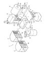
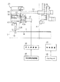
図1は、保護テープ貼付け装置の全体構成を示す斜視図である。 FIG. 1 is a perspective view showing the overall configuration of the protective tape attaching device.
この保護テープ貼付け装置は、図1に示すように、半導体ウエハ(以下、単に「ウエハ」と略称する)Wを収納したカセットCが装填されるウエハ供給/回収部1、ロボットアーム2を備えたウエハ搬送機構3、アライメントステージ4、ウエハWを載置して吸着保持するチャックテーブル5、ウエハWに向けて表面保護用の保護テープTを供給するテープ供給部6、テープ供給部6から供給されたセパレータ付きの保護テープTからセパレータsを剥離回収するセパレータ回収部7、チャックテーブル5に載置されて吸着保持されたウエハWに保護テープTを貼付ける貼付けユニット8、ウエハWに貼付けられた保護テープTをウエハWの外形に沿って切り抜き切断する保護テープ切断装置9、ウエハWに貼付けて切断処理した後の不要テープT’を剥離する剥離ユニット10、剥離ユニット10で剥離された不要テープT’を巻き取り回収するテープ回収部11などが備えられている。上記各構造部および機構について、具体的な構成を以下に説明する。
As shown in FIG. 1, the protective tape attaching apparatus includes a wafer supply / recovery unit 1 and a robot arm 2 in which a cassette C containing a semiconductor wafer (hereinafter simply referred to as “wafer”) W is loaded. Supplied from a wafer transport mechanism 3, an alignment stage 4, a chuck table 5 on which the wafer W is placed and sucked and held, a
ウエハ供給/回収部1には2台のカセットCを並列して装填可能であり、各カセットCには、多数枚のウエハWが配線パターン面(表面)を上向きにした水平姿勢で多段に差込み収納しされている。 The wafer supply / collection unit 1 can be loaded with two cassettes C in parallel. In each cassette C, a large number of wafers W are inserted in multiple stages in a horizontal posture with the wiring pattern surface (surface) facing upward. It is stored.
ウエハ搬送機構3に備えられたロボットアーム2は、水平に進退移動可能に構成されるとともに、全体が駆動旋回および昇降可能となっている。そして、ロボットアーム2の先端には、馬蹄形をした真空吸着式のウエハ保持部2aが備えられている。つまり、カセットCに多段に収納されたウエハW同士の間隙にウエハ保持部2aを差し入れてウエハWを裏面(下面)から吸着保持し、吸着保持したウエハWをカセットCから引き出して、アライメントステージ4、チャックテーブル5、および、ウエハ供給/回収部1の順に搬送するようになっている。 The robot arm 2 provided in the wafer transfer mechanism 3 is configured to be able to move forward and backward horizontally, and can be driven and swung up and down as a whole. The tip of the robot arm 2 is provided with a horseshoe-shaped vacuum suction type wafer holder 2a. That is, the wafer holder 2a is inserted into the gap between the wafers W stored in multiple stages in the cassette C, the wafer W is sucked and held from the back surface (bottom surface), the sucked and held wafer W is pulled out from the cassette C, and the alignment stage 4 The chuck table 5 and the wafer supply / recovery unit 1 are transferred in this order.
アライメントステージ4は、ウエハ搬送機構3によって搬入載置されたウエハWを、その外周に形成されたノッチやオリエンテーションフラットに基づいて位置合わせを行うようになっている。 The alignment stage 4 aligns the wafer W loaded and placed by the wafer transport mechanism 3 based on notches and orientation flats formed on the outer periphery thereof.
チャックテーブル5は、ウエハ搬送機構3から移載されて所定の位置合わせ姿勢で載置されたウエハWを真空吸着するようになっている。また、図6に示すように、このチャックテーブル5の上面には、後述する保護テープ切断装置9に備えたカッタ刃12をウエハWの外形に沿って旋回移動させて保護テープTを切断するためにカッタ走行溝13が形成されている。
The chuck table 5 is configured to vacuum-suck the wafer W transferred from the wafer transfer mechanism 3 and placed in a predetermined alignment posture. Further, as shown in FIG. 6, on the upper surface of the chuck table 5, a
テープ供給部6は、図1に示すように、供給ボビン14から繰り出されたセパレータ付きの保護テープTをガイドローラ15群に巻回案内し、セパレータsを剥離した保護テープTを貼付けユニット8に導くよう構成されている。供給ボビン14は、適度の回転抵抗を与えて過剰なテープ繰り出しが行われないように構成されている。
As shown in FIG. 1, the
セパレータ回収部7は、保護テープTから剥離されたセパレータsを巻き取る回収ボビン16が巻き取り方向に回転駆動されるようになっている。
In the separator collection unit 7, the
貼付けユニット8には貼付けローラ17が前向き水平に備えられており、図8に示すスライド案内機構18および図示されないネジ送り式の駆動機構によって左右水平に往復駆動されるようになっている。
The affixing
剥離ユニット10には剥離ローラ19が前向き水平に備えられており、前記スライド案内機構18および図示されないネジ送り式の駆動機構によって左右水平に往復駆動されるようになっている。
The peeling
テープ回収部11は、不要テープT’を巻き取る回収ボビン20が巻き取り方向に回転駆動されるようになっている。
The
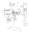
テープ切断機構9は、図2に示すように、駆動昇降可能な可動台21の下部に、チャックテーブル5の中心上に位置する縦軸心X周りに駆動旋回可能に一対の支持アーム22が並列装備されている。また、この支持アーム22の遊端側に備えたカッタユニット23に、刃先を下向きにしたカッタ刃12が装着されている。つまり、支持アーム22が縦軸心Xを旋回中心として旋回することによりカッタ刃12がウエハWの外周に沿って旋回走行して保護テープTを切り抜くよう構成されている。この詳細な構造が図2〜図6に示されている。
As shown in FIG. 2, the
可動台21は、図2に示すように、モータ24を正逆回転駆動することで縦レール25に沿ってねじ送り昇降されるようになっている。この可動台21の遊端部に前記縦軸心X周りに回動可能に装備された回動軸26が、可動台21の上に配備されたモータ27に2本のベルト28を介して減速連動されている。つまり、モータ27の作動によって回動軸26が所定の方向に回動されるようになっている。そして、この回動軸26から下方に延出された支持部材29の下端部に、支持アーム22が水平方向スライド調節可能に貫通支持されている。支持アーム22のスライド調節によってカッタ刃12の旋回中心である縦軸心Xからの距離、つまり、カッタ刃12の旋回半径をウエハ径に対応して変更調節することが可能となっている。
As shown in FIG. 2, the
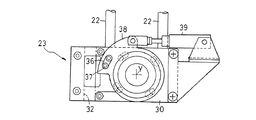
支持アーム22の遊端部にはブラケット30が固着され、このブラケット30にカッタユニット23が装着支持されている。カッタユニット23は、図3および図5に示すように、ブラケット30に縦向き支点Y周りに一定小範囲内で回動可能に支持された回動部材31、回動部材31の端部下面に連結された縦壁状の支持ブラケット32、支持ブラケット32の側面に連結されたカッタ支持部材33、カッタ支持部材33に支持されたブラケット34、このブラケット34に取り付けられたカッタホルダ35などから構成されている。カッタ刃12は、カッタホルダ35の側面に交換可能にネジ連結されている。
A
ここで、回動部材31の上方には、図4に示すように、長孔36と突起37との係合によって回動部材31と一体に回動する操作フランジ38が配備されている。この操作フランジ38をエアーシリンダ39によって回動することにより、支持アーム22に対するカッタユニット23全体の縦向き支点Y周りでの姿勢を変更し、走行方向に対するカッタ刃12の角度を所定の範囲内で調整することが可能となっている。
Here, as shown in FIG. 4, an
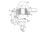
カッタ支持部材33に対してブラケット34は、案内レール機構40を介して支持アーム22の長手方向(図5においては紙面表裏方向)に直線スライド移動可能に支持されている。また、カッタ支持部材33とブラケット34とに亘ってバネ42が張設され、このバネ42の弾性復元力によってブラケット34が縦軸心(旋回中心)Xに近づく方向にスライド付勢されている。なお、バネ42は、本発明の押付付勢手段に相当する。
The
カッタ支持部材33の旋回中心側には、図6および図7に示すように、ブラケット34のスライド方向に沿った姿勢のエアーシリンダ43がステー41を介して固定装備されている。このエアーシリンダ43のピストンロッド43aがブラケット34の端面に当接可能に配備されている。なお、エアーシリンダ43は、本発明の押し戻し手段に相当する。
As shown in FIGS. 6 and 7, an
エアーシリンダ43は、電気制御式の圧力調節器44を介して加圧空気供給装置45に接続されるとともに、圧力調節器44が制御装置46に接続されている。また、回動軸26の上部には、図2に示すように、外周部にノッチや透過孔が等ピッチで形成されたディスク47が固着されるとともに、このディスク47の外周部に対向して電磁式あるいは光電式のパルスセンサ48が配備されている。つまり、ディスク47の回動に応じたパルスがパルスセンサ48から出力されるようになっている。パルスセンサ48からの検出信号は制御装置46に入力され、パルスの周期からカッタ刃12の走行速度が演算されるようになっている。なお、制御装置46は、本発明の制御手段に相当する。
The
次に、上記実施例装置を用いて保護テープTをウエハWの表面に貼付けるための一連の基本動作を図6〜9に基づいて説明する。 Next, a series of basic operations for attaching the protective tape T to the surface of the wafer W using the above-described embodiment apparatus will be described with reference to FIGS.
貼り付け指令が出されると、先ず、ウエハ搬送機構3におけるロボットアーム2がカセット台12に載置装填されたカセットCに向けて移動される。そして、ウエハ保持部2aがカセットCに収容されているウエハ同士の隙間に挿入され、ウエハ保持部2aでウエハWを裏面(下面)から吸着保持して搬出し、取り出したウエハWをアライメントステージ4に移載する。
When a sticking command is issued, first, the robot arm 2 in the wafer transfer mechanism 3 is moved toward the cassette C placed and loaded on the
アライメントステージ4に載置されたウエハWは、ウエハWの外周に形成されているノッチやオリエンテーションフラットを利用して位置合わせされ、位置合わせのすんだウエハWは再びロボットアーム2によって搬出されてチャックテーブル5に載置される。 The wafer W placed on the alignment stage 4 is aligned using notches and orientation flats formed on the outer periphery of the wafer W, and the aligned wafer W is unloaded again by the robot arm 2 and chucked. Placed on the table 5.
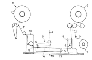
チャックテーブル5に載置されたウエハWは、その中心がチャックテーブル5の中心上にあるように位置合わせされた状態で吸着保持される。この時、図8に示すように、貼付けユニット8と剥離ユニット10は左側の初期位置に、また、テープ切断機構9のカッタ刃12は上方の初期位置でそれぞれ待機している。
The wafer W placed on the chuck table 5 is sucked and held in a state of being aligned so that the center thereof is on the center of the chuck table 5. At this time, as shown in FIG. 8, the affixing
次に、図8の仮想戦で示すように、貼付けユニット8の貼付けローラ17が下降されるとともに、この貼付けローラ17で保護テープTを下方に押圧しながらウエハW上を前方(図8では右方向)に転動する。この転動動作に連動して保護テープTがウエハWの表面全体に貼付けられる。
Next, as shown in the virtual battle of FIG. 8, the affixing
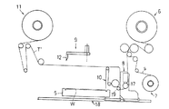
図9に示すように、貼付けユニット8が終端位置に達すると、上方に待機していたカッタ刃12が下降される。このカッタ刃12は、チャックテーブル5のカッタ走行溝13の部分で保護テープTに突き刺される。
As shown in FIG. 9, when the affixing
この場合、図6に示すように、エアーシリンダ43に高い圧の空気が供給されてピストンロッド43aが大きく突出作動し、ブラケット34はバネ42に抗して外方のストロークエンドまでスライド移動されており、カッタ刃12はウエハWの外周縁から外方に少し(数mm)離れた位置で保護テープTに突き刺される。その後、ピストンロッド43aの突出力がバネ力よりも小さくなるようにエアーシリンダ43の空気圧が低減され、図7に示すように、ブラケット34がバネ42の押し付け付勢力でスライド移動されて、カッタ刃12がウエハWの外周に接触される。
In this case, as shown in FIG. 6, high pressure air is supplied to the
カッタ刃12の切断開始位置でカッタ刃12のウエハ外周縁への押し付け設定が終了すると、図10に示すように、支持アーム22が所定の方向に回転され、この回転に伴ってカッタ刃12が縦軸心Xを旋回中心として旋回走行して保護テープTがウエハ外周縁に沿って切断される。
When the pressing setting of the
ウエハ外周縁に沿ったテープ切断が終了すると、図11に示すように、カッタ刃12は上方の待機位置まで上昇されるとともに、剥離ユニット10が前方へ移動しながらウエハW上で切り抜き切断されて残った不要テープT’を巻き上げ剥離する。
When the tape cutting along the outer peripheral edge of the wafer is finished, the
剥離ユニット10が剥離作業の終了位置に達すると、剥離ユニット10と貼付けユニット8とが逆方向に移動して初期位置に復帰する。この時、不要テープT’が回収ボビン20に巻き取られるとともに、一定量の保護テープTがテープ供給部6から繰り出される。
When the peeling
テープ貼付け作動が終了すると、チャックテーブル5における吸着が解除された後、貼付け処理のすんだウエハWはロボットアーム2のウエハ保持部2aに移載されてウエハ供給/回収部1のカセットCに差込み回収される。 When the tape sticking operation is completed, after the suction on the chuck table 5 is released, the wafer W that has been stuck is transferred to the wafer holding part 2a of the robot arm 2 and inserted into the cassette C of the wafer supply / collection part 1. To be recovered.
以上で1回のテープ貼付け処理が完了し、以後、上記作動を順次繰返してゆく。 Thus, one tape attaching process is completed, and thereafter, the above operations are sequentially repeated.
上記テープ切断工程において、パルスセンサ48からの検出信号に基づいて演算されたカッタ刃12の走行速度変動に対応して圧力調節器44が自動調整され、エアーシリンダ43の空気圧が以下のように制御される。
In the tape cutting step, the
図12に、カッタ刃12の走行速度V、エアーシリンダ43に供給される空気圧P、バネ42による押し付け付勢力F、エアーシリンダ43によりカッタ刃12に与えられる押し戻し力h、カッタ刃12に働く遠心力g、および、カッタ刃12のウエハ外周縁への接触圧力cの時間経過に伴う変動が切断開始から切断終了まで示されている。
FIG. 12 shows the traveling speed V of the
カッタ刃12が切断開始位置にセットされて停止している時点においてもエアーシリンダ43には所定の空気圧P1が供給され、バネ42によって与えられた押し付け付勢力Fより小さい所定の押し戻し力hがピストンロッド43aによってブラケット34に付与される。したがって、この時点においてカッタ刃12のウエハ外周への接触圧力cは、バネ42による一定の押し付け付勢力Fからエアーシリンダ43による押し戻し力hを差し引いた値となる(c=F−h)。
Even when the
カッタ刃12の旋回走行が開始されると走行速度Vが上昇(増速)され、これに連れて遠心力gが発生するために、旋回走行中におけるカッタ刃12のウエハ外周縁への接触圧力cは、押し付け付勢力Fから押し戻し力hおよび遠心力gを差し引いた大きさとなる(c=F−f−g)。ここで、カッタ刃12の走行速度Vが上昇するに連れて、エアーシリンダ43に供給される空気圧Pが低下され、ピストンロッド43aによる押し戻し力hが次第に小さくなる。この押し戻し力hの減少量Δhがカッタ刃12の旋回走行により発生する遠心力gに相当する大きさとなるように、予め入力設定されている。例えば、マップデータなどに基づいて空気圧Pが制御され、この制御により、カッタ刃12のウエハ外周縁への接触圧力cが走行開始時点の大きさに維持される。
When the
走行速度Vが予め設定された規定速度V0に到達した後、カッタ12は、この規定速度V0で定速走行される。走行速度Vが規定速度V0に維持されることで、発生する遠心力gが一定となり、これに対応して、エアーシリンダ43の空気圧Pも低い所定値P2に維持され、ピストンロッド43aによる押し戻し力hが一定に維持される。つまり、カッタ刃12のウエハ外周縁への接触圧力cが走行開始時点の大きさに維持される。
After the traveling speed V reaches the preset specified speed V0, the
切断走行が終了近くになると、カッタ刃12の走行速度Vが下降(減速)され、これに連れて遠心力gが減少し、これに対応してエアーシリンダ43の空気圧Pが増大制御され、ピストンロッド43aからの押し戻し力hが次第に大きくなる。つまり、カッタ刃12のウエハ外周縁への接触圧力cが走行開始時点の大きさに維持される。
When the cutting traveling is near the end, the traveling speed V of the
上述のように、カッタ刃12の旋回走行における走行速度変動に対応して押し戻し力hを制御することで、カッタ刃12のウエハ外周縁への接触圧力cをウエハ全周において走行開始時点に設定された大きさに安定維持することができ、切断仕上がりの良好な保護テープ切断がウエハ全周において行われる。また、切断開始位置と終了位置とが一致するので、保護テープTの切り損ないや、切り損ないに伴う保護テープTの剥離時の破損なども解消することができる。
As described above, by controlling the push-back force h in response to the travel speed fluctuation in the turning travel of the
なお、本発明は以下のような形態で実施することも可能である。 The present invention can also be implemented in the following forms.
(1)上記実施例では、カッタ刃12の速度変動を実測してエアーシリンダ43の空気圧制御を行っているが、カッタ刃12が旋回走行される際の、停止状態から規定速度まで速度が増す速度変動の時間特性、および、規定速度から停止するまで減速する速度変動の時間特性が予め設定されている場合には、カッタ刃12の切断開始位置からの時間経過の検出、あるいは、カッタ刃12が走行開始した時点からの走行量の検出に基づいて速度変動を間接的に割り出し、この変動情報に基づいてエアーシリンダ43の空気圧制御を行っても同等の機能を発揮させることができる。
(1) In the above-described embodiment, the speed variation of the
(2)カッタユニット23の適所に加速度センサを装備してカッタ刃12の走行速度変動を直接的に検出し、この検出情報に基づいてエアーシリンダ43の空気圧制御を行うこともできる。
(2) It is also possible to equip an appropriate position of the
(3)本発明は、バネ42による押し付け付勢力Fそのものを制御して安定した接触圧力cを得ることもできる。例えば、図13の原理図に示すように、エアーシリンダ43は、カッタ刃12をテープ突入位置と切断開始位置に移動させるためだけに利用し、バネ42の固定端を電磁ソレノイドや電動モータなどの電動アクチュエータ49に連結する。そして、パルスセンサ48の検出情報に基づいて割り出された走行速度の変動に応じて電動アクチュエータ49を作動制御してバネ42の固定端を自動的に位置調節し、走行に伴ってカッタ刃12に働く遠心力gを相殺するようにバネ42の張力をカッタ刃12の速度変動に基づいて制御する。この構成により、カッタ刃12のウエハ外周縁への接触圧力cを全周において安定維持するよう構成することも可能である。
(3) The present invention can also obtain the stable contact pressure c by controlling the pressing biasing force F itself by the
(4)本発明の装置は、制御装置46などを用いることなく、バネ42による押し付け付勢力Fそのものを走行速度変動に対応して機械的に自動制御することもできる。例えば、図14の原理図に示すように、カッタユニット23における固定部位にカッタ走行方向と平行する支点Z周りに揺動自在な作動アーム50を設ける。また、この作動アーム50の下端部に、押し付け付勢用のバネ42の固定端を連結支持するとともに、作動アーム50の上部にバランスウエイト51を装備する。
(4) The apparatus of the present invention can also mechanically automatically control the pressing and urging force F itself by the
この構成により、カッタ刃12が停止している状態では、バネ42の張力を受ける作動アーム50は、ストッパ52に受け止められて所定の姿勢に保持され、バネ42による押し付け付勢力が所定の大きさに設定される。カッタ刃12が旋回走行を開始するとバランスウエイト51に働く遠心力によって作動アーム50が揺動されてバネ42の張力が増大される。この動作に連動して、カッタ刃12に作用する遠心力による押し付け付勢力が減少する分だけ押し付け付勢力を付加し、カッタ刃12のウエハ外周縁への接触圧力cを全周において安定維持するよう構成することもできる。
With this configuration, when the
12 … カッタ刃
42 … バネ
43 … エアーシリンダ
T … 保護テープ
c … 接触圧力
F … 押し付け付勢力
h … 押し戻し力
g … 遠心力
P … 空気圧
W … 半導体ウエハ
DESCRIPTION OF
Claims (4)
ウエハ径方向に移動可能に支持した前記カッタ刃を半導体ウエハの外周縁に押し付け付勢するとともに、この押し付け付勢力をカッタ刃の走行速度変動に対応させて自動調整制御し、半導体ウエハの外周縁に対するカッタ刃の接触圧力を安定維持する
ことを特徴とする半導体ウエハの保護テープ切断方法。 A semiconductor wafer protective tape cutting method, wherein the cutter blade is swung along the outer peripheral edge of the semiconductor wafer, and the protective tape attached to the surface of the semiconductor wafer is cut out along the wafer outer shape,
The cutter blade supported so as to be movable in the wafer radial direction is pressed and urged against the outer peripheral edge of the semiconductor wafer, and this pressing and urging force is automatically adjusted and controlled in accordance with the fluctuation of the cutter blade's running speed. A method for cutting a protective tape of a semiconductor wafer, comprising maintaining a stable contact pressure of a cutter blade against the semiconductor wafer.
前記カッタ刃にウエハの外周縁に向かう一定の押し付け付勢力を付与するとともに、この押し付け付勢力より小さい制御用の押し戻し力を逆方向から付与し、この押し戻し力をカッタ刃の走行速度変動に対応させて自動調整制御する
ことを特徴とする半導体ウエハの保護テープ切断方法。 In the semiconductor wafer protective tape cutting method according to claim 1,
A constant pressing biasing force toward the outer peripheral edge of the wafer is applied to the cutter blade, and a control pushing back force smaller than the pressing biasing force is applied from the opposite direction, and this pushing back force corresponds to the fluctuation of the cutter blade traveling speed. A method for cutting a protective tape of a semiconductor wafer, wherein automatic adjustment control is performed.
ウエハ径方向に移動可能に支持した前記カッタ刃に半導体ウエハの外周縁に向かう一定の押し付け付勢力を付与する押し付け付勢手段と、
前記押し付け付勢力より小さい押し戻し力を押し付け付勢方向と逆方向にカッタ刃に付与する押し戻し手段と、
この押し戻し手段による押し戻し力をカッタ刃の走行速度変動に対応させて自動調整制御する制御手段と、
を備えたことを特徴とする半導体ウエハの保護テープ切断装置。 A semiconductor wafer protective tape cutting device for rotating a cutter blade along an outer peripheral edge of a semiconductor wafer and cutting out a protective tape attached to the surface of the semiconductor wafer along the outer shape of the wafer,
A pressing biasing means for applying a constant pressing biasing force toward the outer peripheral edge of the semiconductor wafer to the cutter blade supported so as to be movable in the wafer radial direction;
A pushing-back means for applying a pushing-back force smaller than the pushing-urging force to the cutter blade in a direction opposite to the pushing-urging direction;
A control means for automatically adjusting and controlling the push-back force by the push-back means in correspondence with the traveling speed fluctuation of the cutter blade;
A protective tape cutting device for a semiconductor wafer, comprising:
前記押し付け付勢手段は、バネの弾性復元力で前記カッタ刃を半導体ウエハの外周縁に向けて押し付け付勢するよう構成したものであり、
前記押し戻し手段は、エアーシリンダでカッタ刃を押し付け付勢方向と逆方向に押圧するよう構成したものであり、
前記制御手段は、前記エアーシリンダに供給される空気圧をカッタ刃の走行速度変動に対応させて自動調整制御するよう構成した
ことを特徴とする半導体ウエハの保護テープ切断装置。 In the semiconductor wafer protective tape cutting device according to claim 3,
The pressing and biasing means is configured to press and bias the cutter blade toward the outer peripheral edge of the semiconductor wafer by an elastic restoring force of a spring,
The push-back means is configured to press the cutter blade with an air cylinder and press it in the direction opposite to the biasing direction.
The control means is configured to automatically adjust and control the air pressure supplied to the air cylinder in accordance with fluctuations in the traveling speed of the cutter blade. A semiconductor wafer protective tape cutting device.
Priority Applications (5)
| Application Number | Priority Date | Filing Date | Title |
|---|---|---|---|
| JP2006307726A JP4642002B2 (en) | 2006-11-14 | 2006-11-14 | Semiconductor wafer protective tape cutting method and protective tape cutting device |
| US11/979,932 US8042441B2 (en) | 2006-11-14 | 2007-11-09 | Method for cutting protective tape of semiconductor wafer and apparatus for cutting the protective tape |
| TW096142774A TWI368269B (en) | 2006-11-14 | 2007-11-13 | Method for cutting protective tape of semiconductor wafer and apparatus for cutting the protective tape |
| KR1020070115307A KR101311567B1 (en) | 2006-11-14 | 2007-11-13 | Method for cutting protective tape of semiconductor wafer and apparatus for cutting the protective tape |
| CN2007101878687A CN101183641B (en) | 2006-11-14 | 2007-11-14 | Method for cutting protective tape of semiconductor wafer and apparatus for cutting the protective tape |
Applications Claiming Priority (1)
| Application Number | Priority Date | Filing Date | Title |
|---|---|---|---|
| JP2006307726A JP4642002B2 (en) | 2006-11-14 | 2006-11-14 | Semiconductor wafer protective tape cutting method and protective tape cutting device |
Publications (2)
| Publication Number | Publication Date |
|---|---|
| JP2008124307A JP2008124307A (en) | 2008-05-29 |
| JP4642002B2 true JP4642002B2 (en) | 2011-03-02 |
Family
ID=39369694
Family Applications (1)
| Application Number | Title | Priority Date | Filing Date |
|---|---|---|---|
| JP2006307726A Expired - Fee Related JP4642002B2 (en) | 2006-11-14 | 2006-11-14 | Semiconductor wafer protective tape cutting method and protective tape cutting device |
Country Status (5)
| Country | Link |
|---|---|
| US (1) | US8042441B2 (en) |
| JP (1) | JP4642002B2 (en) |
| KR (1) | KR101311567B1 (en) |
| CN (1) | CN101183641B (en) |
| TW (1) | TWI368269B (en) |
Families Citing this family (7)
| Publication number | Priority date | Publication date | Assignee | Title |
|---|---|---|---|---|
| JP5412260B2 (en) * | 2009-12-10 | 2014-02-12 | 日東電工株式会社 | Adhesive tape pasting method and apparatus using the same |
| KR101981639B1 (en) * | 2012-11-13 | 2019-05-27 | 삼성디스플레이 주식회사 | Sheet cutting apparatus and the sheet cutting method using the same |
| JP6122311B2 (en) * | 2013-02-28 | 2017-04-26 | 日東電工株式会社 | Adhesive tape cutting method and adhesive tape piece cutting apparatus |
| JP7273614B2 (en) * | 2019-05-17 | 2023-05-15 | リンテック株式会社 | SEAT SUPPORT DEVICE AND SEAT SUPPORT METHOD |
| JP7360812B2 (en) * | 2019-05-17 | 2023-10-13 | リンテック株式会社 | Seat support device and seat support method |
| CN112318691A (en) * | 2020-12-04 | 2021-02-05 | 禹州市国粹钧窑有限责任公司 | Jun porcelain bottle mouth processing method and device |
| CN114030094B (en) * | 2021-11-18 | 2022-12-09 | 江苏纳沛斯半导体有限公司 | Silicon chip scribing system capable of preventing edge breakage during semiconductor wafer preparation |
Citations (3)
| Publication number | Priority date | Publication date | Assignee | Title |
|---|---|---|---|---|
| JPH10112492A (en) * | 1996-10-07 | 1998-04-28 | Teikoku Seiki Kk | Method and apparatus for cutting wafer protective tape |
| JP2006005131A (en) * | 2004-06-17 | 2006-01-05 | Disco Abrasive Syst Ltd | Method and apparatus for setting masking tape |
| JP2006055935A (en) * | 2004-08-19 | 2006-03-02 | Nitto Denko Corp | Protective tape sticking device |
Family Cites Families (9)
| Publication number | Priority date | Publication date | Assignee | Title |
|---|---|---|---|---|
| US4603609A (en) * | 1983-10-21 | 1986-08-05 | Disco Abrasive Systems, Ltd. | Apparatus for cutting a sheet-like member applied to a surface of a semiconductor wafer |
| US4626320A (en) * | 1984-02-22 | 1986-12-02 | Conoco Inc. | Method for automated de-coking |
| JPH01143211A (en) * | 1987-11-27 | 1989-06-05 | Takatori Haitetsuku:Kk | Sticking and cutting of protective tape for wafer and device therefor |
| US6080263A (en) * | 1997-05-30 | 2000-06-27 | Lintec Corporation | Method and apparatus for applying a protecting film to a semiconductor wafer |
| JP3919292B2 (en) * | 1997-05-30 | 2007-05-23 | リンテック株式会社 | Method and apparatus for cutting semiconductor wafer protective film |
| JP3983053B2 (en) * | 2002-01-17 | 2007-09-26 | 日東電工株式会社 | Protective tape cutting method and protective tape applying apparatus using the same |
| JP2004025402A (en) | 2002-06-27 | 2004-01-29 | Lintec Corp | Cutting method and cutting device of protection tape of semiconductor wafer |
| JP4530638B2 (en) * | 2003-10-07 | 2010-08-25 | 日東電工株式会社 | Method and apparatus for applying protective tape to semiconductor wafer |
| JP4472316B2 (en) | 2003-11-28 | 2010-06-02 | 日東電工株式会社 | Adhesive tape cutting method and adhesive tape cutting device |
-
2006
- 2006-11-14 JP JP2006307726A patent/JP4642002B2/en not_active Expired - Fee Related
-
2007
- 2007-11-09 US US11/979,932 patent/US8042441B2/en not_active Expired - Fee Related
- 2007-11-13 KR KR1020070115307A patent/KR101311567B1/en active IP Right Grant
- 2007-11-13 TW TW096142774A patent/TWI368269B/en not_active IP Right Cessation
- 2007-11-14 CN CN2007101878687A patent/CN101183641B/en not_active Expired - Fee Related
Patent Citations (3)
| Publication number | Priority date | Publication date | Assignee | Title |
|---|---|---|---|---|
| JPH10112492A (en) * | 1996-10-07 | 1998-04-28 | Teikoku Seiki Kk | Method and apparatus for cutting wafer protective tape |
| JP2006005131A (en) * | 2004-06-17 | 2006-01-05 | Disco Abrasive Syst Ltd | Method and apparatus for setting masking tape |
| JP2006055935A (en) * | 2004-08-19 | 2006-03-02 | Nitto Denko Corp | Protective tape sticking device |
Also Published As
| Publication number | Publication date |
|---|---|
| US8042441B2 (en) | 2011-10-25 |
| CN101183641B (en) | 2011-04-20 |
| KR20080043718A (en) | 2008-05-19 |
| TWI368269B (en) | 2012-07-11 |
| CN101183641A (en) | 2008-05-21 |
| JP2008124307A (en) | 2008-05-29 |
| KR101311567B1 (en) | 2013-09-26 |
| TW200834700A (en) | 2008-08-16 |
| US20080113492A1 (en) | 2008-05-15 |
Similar Documents
| Publication | Publication Date | Title |
|---|---|---|
| JP4642002B2 (en) | Semiconductor wafer protective tape cutting method and protective tape cutting device | |
| JP4360684B2 (en) | Adhesive tape pasting method for semiconductor wafer and apparatus using the same | |
| US7516768B2 (en) | Method and apparatus for joining protective tape | |
| CN101060068B (en) | Method for separating protective tape, and apparatus using the same | |
| JP4895766B2 (en) | Semiconductor wafer protective tape cutting method and protective tape cutting device | |
| US7789121B2 (en) | Sheet sticking apparatus and sticking method | |
| US7357165B2 (en) | Method and apparatus for cutting protective tape | |
| EP1962324B1 (en) | Adhesive tape joining apparatus | |
| JP5324317B2 (en) | Protective tape application method and protective tape application device | |
| US8021509B2 (en) | Method for affixing adhesive tape to semiconductor wafer, and apparatus using the same | |
| CN101847571A (en) | Boundary belt stripping means and the boundary belt stripping off device that adopts this method | |
| CN104600017A (en) | Protective tape separating method and protective tape separating apparatus | |
| JP6087515B2 (en) | Semiconductor wafer protective tape cutting method and protective tape cutting device | |
| JP2010114244A (en) | Sheet peeling device and method | |
| JP2013230532A (en) | Protective tape cutting method and protective tape cutting apparatus of semiconductor wafer | |
| JP2580276B2 (en) | Taping device for winding | |
| JP3129468B2 (en) | Wire electric discharge machine | |
| JPH08318526A (en) | Apparatus for recovering wafer of slicing machine | |
| JP2002018603A (en) | Bar material supply device | |
| JPH07148731A (en) | Cutting device of slicing machine |
Legal Events
| Date | Code | Title | Description |
|---|---|---|---|
| A621 | Written request for application examination |
Free format text: JAPANESE INTERMEDIATE CODE: A621 Effective date: 20090219 |
|
| A977 | Report on retrieval |
Free format text: JAPANESE INTERMEDIATE CODE: A971007 Effective date: 20101126 |
|
| TRDD | Decision of grant or rejection written | ||
| A01 | Written decision to grant a patent or to grant a registration (utility model) |
Free format text: JAPANESE INTERMEDIATE CODE: A01 Effective date: 20101130 |
|
| A01 | Written decision to grant a patent or to grant a registration (utility model) |
Free format text: JAPANESE INTERMEDIATE CODE: A01 |
|
| A61 | First payment of annual fees (during grant procedure) |
Free format text: JAPANESE INTERMEDIATE CODE: A61 Effective date: 20101130 |
|
| R150 | Certificate of patent or registration of utility model |
Ref document number: 4642002 Country of ref document: JP Free format text: JAPANESE INTERMEDIATE CODE: R150 Free format text: JAPANESE INTERMEDIATE CODE: R150 |
|
| FPAY | Renewal fee payment (event date is renewal date of database) |
Free format text: PAYMENT UNTIL: 20131210 Year of fee payment: 3 |
|
| FPAY | Renewal fee payment (event date is renewal date of database) |
Free format text: PAYMENT UNTIL: 20131210 Year of fee payment: 3 |
|
| FPAY | Renewal fee payment (event date is renewal date of database) |
Free format text: PAYMENT UNTIL: 20161210 Year of fee payment: 6 |
|
| R250 | Receipt of annual fees |
Free format text: JAPANESE INTERMEDIATE CODE: R250 |
|
| R250 | Receipt of annual fees |
Free format text: JAPANESE INTERMEDIATE CODE: R250 |
|
| LAPS | Cancellation because of no payment of annual fees |