JP4641387B2 - Fluid coupling - Google Patents
Fluid coupling Download PDFInfo
- Publication number
- JP4641387B2 JP4641387B2 JP2004163141A JP2004163141A JP4641387B2 JP 4641387 B2 JP4641387 B2 JP 4641387B2 JP 2004163141 A JP2004163141 A JP 2004163141A JP 2004163141 A JP2004163141 A JP 2004163141A JP 4641387 B2 JP4641387 B2 JP 4641387B2
- Authority
- JP
- Japan
- Prior art keywords
- fuel
- pulsation
- bellows
- fluid coupling
- resin
- Prior art date
- Legal status (The legal status is an assumption and is not a legal conclusion. Google has not performed a legal analysis and makes no representation as to the accuracy of the status listed.)
- Expired - Fee Related
Links
Images


Classifications
-
- F—MECHANICAL ENGINEERING; LIGHTING; HEATING; WEAPONS; BLASTING
- F02—COMBUSTION ENGINES; HOT-GAS OR COMBUSTION-PRODUCT ENGINE PLANTS
- F02M—SUPPLYING COMBUSTION ENGINES IN GENERAL WITH COMBUSTIBLE MIXTURES OR CONSTITUENTS THEREOF
- F02M37/00—Apparatus or systems for feeding liquid fuel from storage containers to carburettors or fuel-injection apparatus; Arrangements for purifying liquid fuel specially adapted for, or arranged on, internal-combustion engines
- F02M37/0011—Constructional details; Manufacturing or assembly of elements of fuel systems; Materials therefor
- F02M37/0041—Means for damping pressure pulsations
-
- F—MECHANICAL ENGINEERING; LIGHTING; HEATING; WEAPONS; BLASTING
- F02—COMBUSTION ENGINES; HOT-GAS OR COMBUSTION-PRODUCT ENGINE PLANTS
- F02M—SUPPLYING COMBUSTION ENGINES IN GENERAL WITH COMBUSTIBLE MIXTURES OR CONSTITUENTS THEREOF
- F02M55/00—Fuel-injection apparatus characterised by their fuel conduits or their venting means; Arrangements of conduits between fuel tank and pump F02M37/00
- F02M55/04—Means for damping vibrations or pressure fluctuations in injection pump inlets or outlets
-
- F—MECHANICAL ENGINEERING; LIGHTING; HEATING; WEAPONS; BLASTING
- F16—ENGINEERING ELEMENTS AND UNITS; GENERAL MEASURES FOR PRODUCING AND MAINTAINING EFFECTIVE FUNCTIONING OF MACHINES OR INSTALLATIONS; THERMAL INSULATION IN GENERAL
- F16L—PIPES; JOINTS OR FITTINGS FOR PIPES; SUPPORTS FOR PIPES, CABLES OR PROTECTIVE TUBING; MEANS FOR THERMAL INSULATION IN GENERAL
- F16L55/00—Devices or appurtenances for use in, or in connection with, pipes or pipe systems
- F16L55/04—Devices damping pulsations or vibrations in fluids
- F16L55/045—Devices damping pulsations or vibrations in fluids specially adapted to prevent or minimise the effects of water hammer
- F16L55/05—Buffers therefor
- F16L55/052—Pneumatic reservoirs
- F16L55/053—Pneumatic reservoirs the gas in the reservoir being separated from the fluid in the pipe
-
- Y—GENERAL TAGGING OF NEW TECHNOLOGICAL DEVELOPMENTS; GENERAL TAGGING OF CROSS-SECTIONAL TECHNOLOGIES SPANNING OVER SEVERAL SECTIONS OF THE IPC; TECHNICAL SUBJECTS COVERED BY FORMER USPC CROSS-REFERENCE ART COLLECTIONS [XRACs] AND DIGESTS
- Y10—TECHNICAL SUBJECTS COVERED BY FORMER USPC
- Y10T—TECHNICAL SUBJECTS COVERED BY FORMER US CLASSIFICATION
- Y10T29/00—Metal working
- Y10T29/49—Method of mechanical manufacture
- Y10T29/49826—Assembling or joining
Landscapes
- Engineering & Computer Science (AREA)
- General Engineering & Computer Science (AREA)
- Mechanical Engineering (AREA)
- Chemical & Material Sciences (AREA)
- Combustion & Propulsion (AREA)
- Pipe Accessories (AREA)
- Fuel-Injection Apparatus (AREA)
Description
本発明は、流体継手に関し、例えば、自動車の燃料供給系などに用いるのに好適な流体継手に関するものである。 The present invention relates to a fluid coupling and, for example, to a fluid coupling suitable for use in an automobile fuel supply system.
図10に示す自動車の燃料供給系は、リターン式と呼ばれるもので、図外の燃料タンクからの燃料を、床下の供給配管101及び供給チューブを102を介してデリバリーパイプ103に供給し、同燃料をデリバリーパイプ103から各気筒のフュエルインジェクタ104に供給する。デリバリーパイプ103には、プレッシャーレギュレータ105が設けてあって、このプレッシャーレギュレータ105により、余剰燃料をリターンチューブ106及び床下のリターン配管107から燃料タンクに戻すことで、デリバリーパイプ103内の圧力を一定に保つようにしている。
The fuel supply system of the automobile shown in FIG. 10 is called a return type, and supplies fuel from a fuel tank (not shown) to the
また、図11に示す自動車の燃料供給系は、リターンレス式と呼ばれるもので、図外の燃料タンクからの燃料を、床下の供給配管101及び供給チューブを102を介してデリバリーパイプ103に供給し、同燃料をデリバリーパイプ103から各フュエルインジェクタ104に供給するようになっており、この際、燃料ポンプの吐出運動やフュエルインジェクタ104の燃料噴射運動に起因する燃料の脈動及び脈動音を抑制するために、デリバリーパイプ103にパルセーションダンパ108が設けてある。
Further, the fuel supply system of the automobile shown in FIG. 11 is called a returnless type, and supplies fuel from a fuel tank (not shown) to the
上記の各燃料供給系では、供給配管101と供給チューブ102の間、供給チューブ102とデリバリーパイプ103の間、プレッシャーレギュレータ105とリターンチューブ106の間、及びリターンチューブ106とリターン配管107の間に、クイックコネクタと呼ばれる流体継手110が各々設けてある。この流体継手110は、金属や樹脂から成ると共に、接続部分に1つ又は2つのOリングを備えたものが一般的であり、ストレートタイプやエルボータイプのものが周知である。
ところで、近年では、自動車の軽量化やコストダウンを図るためにさらなる改善が望まれており、燃料供給系においては、リターン式よりも部品点数の少ないリターンレス式のものが増えつつある。 By the way, in recent years, further improvements have been desired in order to reduce the weight and cost of automobiles, and the number of returnless types with fewer parts than the return type is increasing in the fuel supply system.
しかしながら、リターンレス式の燃料供給系にあっては、リターン式に比べてデリバリーパイプ103側で燃料の脈動が発生し易いため、上述したようにパルセーションダンパ108が不可欠である。このため、デリバリーパイプ103にパルセーションダンパ108を結合するためのフランジ等の取付け部や、結合部分をシールする構造が必要であり、これらによって構造が複雑化し、充分なコストダウンを図ることが難しいと共に、エンジンルーム内の狭いスペースにレイアウトする際に支障が生じるといった問題点があった。
However, in the returnless type fuel supply system, the
本発明は、上記従来の状況に鑑みて成されたもので、リターンレス式の燃料供給系において、小型で且つ安価であると共に、限られたスペースで効率良く燃料の脈動を抑制することができる流体継手を提供することを目的としている。 The present invention has been made in view of the above-described conventional situation, and in a returnless type fuel supply system, is small and inexpensive, and can efficiently suppress fuel pulsation in a limited space. It aims to provide a fluid coupling.
本発明の流体継手は、リターンレス式の燃料供給系において、フュエルインジェクタに燃料を供給するデリバリーパイプとデリバリーパイプに燃料を供給する供給チューブとを接続する流体継手であって、継手内部に、流体経路と、流体経路内にあって流体経路を流れる燃料の脈動を吸収する脈動吸収体とを備え、脈動吸収体が、樹脂又はゴムから成り且つ燃料の脈動と同じ方向に伸縮変形することにより空気ばねとして機能するベローズを備えており、燃料通過用の開口を有する支持体によって前記ベローズを流体経路内に支持したことを特徴としており、脈動吸収体で燃料の脈動を吸収することで、当該流体継手を用いた燃料流通系で発生する燃料の脈動を抑制する。 A fluid coupling according to the present invention is a fluid coupling that connects a delivery pipe that supplies fuel to a fuel injector and a supply tube that supplies fuel to the delivery pipe in a returnless fuel supply system. And a pulsation absorber that absorbs the pulsation of fuel flowing in the fluid path in the fluid path , and the pulsation absorber is made of resin or rubber and expands and contracts in the same direction as the pulsation of the fuel. includes a bellows that acts as a spring, the support having an opening for the fuel passage and characterized by supporting the bellows within the fluid path, to absorb the pulsation of the fuel in the pulsation absorber, Suppresses fuel pulsation generated in the fuel flow system using the fluid coupling.
本発明の流体継手によれば、リターンレス式の燃料供給系において、脈動吸収体の余分な設置スペースを必要とせずに、燃料の脈動を効率良く吸収することができ、これにより、燃料流通系で発生する様々な燃料の脈動を抑制することができると共に、このような脈動抑制機能を小型の構成で安価に得ることが可能となる。そして、構成が小型であることから、燃料供給系の軽量化や低コスト化に貢献することができ、スペースが限られたエンジンルーム内のレイアウトにも容易に対処し得るものとなる。また、本発明の流体継手は、ベローズの配置部位において、狭くなった流体経路がオリフィスの役目を果たすこととなり、これにより脈動の伝達を低く抑えることができる。 According to the fluid coupling of the present invention, in the returnless type fuel supply system, it is possible to efficiently absorb the fuel pulsation without requiring an extra installation space for the pulsation absorber. As a result, it is possible to suppress the pulsation of various fuels generated in the above, and to obtain such a pulsation suppressing function with a small configuration at low cost. And since the structure is small, it can contribute to the weight reduction and cost reduction of a fuel supply system, and can easily cope with the layout in the engine room where the space is limited. Further, in the fluid coupling according to the present invention, the narrowed fluid path serves as an orifice in the bellows arrangement site, thereby suppressing pulsation transmission to a low level.
以下、図面に基づいて、本発明の流体継手の実施例を説明する。なお、以下の各実施例では、先に説明した図11に示すリターンレス式の燃料供給系において、供給チューブ102とデリバリーパイプ103とを接続する流体継手(クイックコネクタ)に用いるものを示している。
Hereinafter, with reference to the drawings, an embodiment of a fluid coupling of the present invention to explain. In the following embodiments, the fuel supply system of the returnless type shown in FIG. 11 described above, that shows those used in fluid coupling for connecting a
図1は本発明の流体継手の一実施例を説明する図である。図示の流体継手A1は、ストレートタイプであって、内側に2つのOリング1,1とバックアップリング2を装着した一方の接続部J1と、外周にチューブ抜け止め用の突部3を形成した他方の接続部J2を一体的に備えている。そして、一方の接続部J1の内側に、スペーサ4とともに金属製パイプ(デリバリーパイプ)Pを接続し、他方の接続部J2の外側に、樹脂製チューブ(供給チューブ)Tを接続して、流体である燃料を流通させる。
FIG. 1 is a view for explaining an embodiment of the fluid coupling of the present invention. The illustrated fluid coupling A1 is a straight type, and has one connecting portion J1 with two O-
流体継手A1は、継手本体の材料として、燃料に対して耐久性を有するものが用いられ、例えば、ポリアミド、ポリオレフィン、ポリスルフィド、ふっ素樹脂、ポリエステル、ポリアセタール及びポリケトンから成る群より選ばれた樹脂を主成分とする材料で成形してある。 In the fluid coupling A1, a material having durability against the fuel is used as the material of the coupling body. For example, a resin selected from the group consisting of polyamide, polyolefin, polysulfide, fluorine resin, polyester, polyacetal, and polyketone is mainly used. Molded with ingredients.
上記の流体継手A1は、流体経路5内に、流体経路5を流れる燃料の脈動と同じ方向に変形して燃料の脈動を吸収する脈動吸収体が配置してあると共に、脈動吸収体の配置部位の流体経路断面が、非配置部位の流路経路断面よりも小さいものとなっている。そして、この実施例では、脈動吸収体として、流体経路5内に固定した支持体6により支持したベローズ7を用いている。
In the fluid coupling A1, a pulsation absorber that deforms in the same direction as the pulsation of the fuel flowing in the
支持体6は、継手本体と同種の材料から成るものであって、具体例としては、ガラス繊維を強化材としたポリアミド12樹脂を用いており、燃料を充分に通過させるための開口を有すると共に、回転溶着により継手本体に固定してある。
The support 6 is made of the same material as that of the joint body. As a specific example, the support 6 is made of
ベローズ7は、樹脂又はゴムから成るものであって、具体例としては、ポリアミド12樹脂を用いており、ブロー成形により成形してあると共に、支持体6に対して気密的に溶着連結してあり、空気ばねとして機能する。なお、ベローズ7の材料としては、上記したポリアミド12樹脂のほか、ポリアミド系、ポリオレフィン系、ふっ素系、ポリエステル系及びポリスルフィド系等の熱可塑性樹脂、熱可塑性エラストマー、ふっ素系、ニトリル系及びアクリル系等のゴムを用いることができる。
The
上記構成を備えた流体継手A1は、脈動吸収体であるベローズ7が流体経路5内に配置されて燃料の脈動と同じ方向に変形することとなり、燃料の脈動を効率良く吸収することができる。すなわち、リターンレス式の燃料供給系において、燃料タンクからの燃料を金属製パイプPに供給し、同パイプP側の燃料の脈動すなわちフュエルインジェクタ(図11の符号104)の燃料噴射運動に起因する燃料の脈動が生じた場合には、その脈動波の伝播方向に対向するベローズ7が伸縮変形して脈動を効率的に吸収することができる。
In the fluid coupling A1 having the above-described configuration, the
このように、上記の流体継手A1は、流体経路5内に、空気ばねとして機能するベローズ7を配置したことにより、小型で且つ部品点数の少ない簡単な構造であるうえに、燃料供給系で発生する脈動を抑制し得るものとなる。そして、図11に示すリターンレス式の燃料供給系において、パルセーションダンパを廃止することが可能になり、燃料供給系の軽量化や低コスト化を実現すると共に、スペースが限られたエンジンルーム内のレイアウトにも容易に対処し得るものとなる。
As described above, the fluid coupling A1 has a simple structure with a small size and a small number of parts due to the arrangement of the
また、上記の流体継手A1は、脈動吸収体であるベローズ7が樹脂又はゴムで成形してあるので、それ自体が軽量で且つ安価であり、しかも、ベローズ7の変形効率が良いので脈動を効果的に吸収することができると共に、樹脂又はゴムは成形性が良いので、所定のばね定数が得られるようにベローズ7を成形することも容易である。
In the fluid coupling A1, the
さらに、上記の流体継手A1では、継手本体に対して支持体6を回転溶着し、この支持体6に対してベローズ7を溶着連結することから、連結部品を一切用いることなく夫々の部品を互いに容易に且つ確実に連結することができ、構造のさらなる簡略化や軽量化を実現することができる。
Further, in the fluid coupling A1, the support 6 is rotationally welded to the joint body, and the
さらに、上記の流体継手A1は、図11に示す燃料供給系において、供給配管101と供給チューブ102の間に設けることもでき、この場合には、一方の接続部J1に供給配管101を接続することにより、燃料ポンプの吐出運動に起因する脈動を吸収することができる。
Furthermore, the fluid coupling A1 can be provided between the
そしてさらに、上記の流体継手A1は、脈動吸収体(ベローズ7)の配置部位の流体経路断面を、非配置部位の流路経路断面よりも小さいものとしたことにより、脈動吸収体(ベローズ7)の配置部位において狭くなった流体経路がオリフィスの役目を果たすこととなり、これにより脈動の伝達を低く抑えることができる。 Further, the fluid coupling A1 has a pulsation absorber (bellows 7) in which the fluid path cross section of the arrangement site of the pulsation absorber (bellows 7) is smaller than the flow path path cross section of the non-arrangement site. The fluid path narrowed at the position of the arrangement serves as an orifice, whereby the transmission of pulsations can be kept low.
図2は、本発明の流体継手の参考例を説明する図である。なお、先の実施例と同一の構成部位は、同一符号を付して詳細な説明を省略する。 FIG. 2 is a view for explaining a reference example of the fluid coupling of the present invention. Note that the same components as those in the previous embodiment are denoted by the same reference numerals and detailed description thereof is omitted.
図示の流体継手A2は、エルボータイプであって、先の実施例と同様の一方の接続部J1と、一方の接続部J1に対してほぼ直交した他方の接続部J2を一体的に備えており、エルボー部分に、一方の接続部J1と同軸状に延長してその先端部を開放した延長部Eを有し、この延長部Eに、支持体11と、流体経路5を流れる燃料の脈動を吸収する脈動吸収体を備えている。
The illustrated fluid coupling A2 is an elbow type, and integrally includes one connection portion J1 similar to the previous embodiment and the other connection portion J2 substantially orthogonal to the one connection portion J1. The elbow part has an extension E that extends coaxially with one of the connecting parts J1 and opens its tip, and the pulsation of the fuel flowing through the
支持体11は、この参考例では、ガラス繊維を強化材としたポリアミド12樹脂から成る板部材であって、脈動吸収体を取付けた後、回転溶着により延長部Eの開放端部を閉塞するように固定してある。
In this reference example , the
脈動吸収体は、先の実施例と同様に樹脂又はゴムから成るベローズ7と、ベローズ7の内部においてベローズ7とともに伸縮する弾性体を備えており、ここでは、弾性体として樹脂又はゴムから成る成形体12を用いている。この成形体12は、円柱状に圧縮成形したふっ素ゴム製であって、ベローズ7と同軸状に設けてある。
The pulsation absorber includes a
なお、成形体12の材料としては、上記したふっ素ゴムのほか、ニトリルゴム、アクリルゴム、シリコーンゴム、ふっ素化シリコーンゴム、ヒドリンゴム、ウレタンゴム、エチレンプロピレンゴム及びブチルゴム等の各種ゴムや、ポリオレフィン、ポリスルフィド、ふっ素樹脂、ポリエステル、ポリアセタール、ポリケトン、ポリ塩化ビニル及び熱可塑性エラストマーなどの各種樹脂を用いることができる。
As the material of the molded
上記の流体継手A2は、脈動吸収体であるベローズ7及び成形体12が、空気ばね+ゴムばねとして機能することとなり、なお且つ、樹脂又はゴムから成るベローズ7及び成形体12は夫々ダンピング効果が高いので、燃料の圧力が比較的高い場合であっても、燃料の脈動を高効率で吸収することができる。
In the fluid coupling A2, the
また、脈動吸収体をベローズ7と成形体12との組み合わせとしたことで、脈動吸収体におけるばね定数の設定の自由度を高めることが可能となり、これにより様々な大きさの圧力及び圧力脈動に対応し得るほか、先の実施例と同様に、小型で且つ部品点数の少ない簡単な構造であるうえに、燃料供給系の軽量化や低コスト化を実現し、スペースが限られたエンジンルーム内のレイアウトにも容易に対処し得るものとなる。
In addition, by combining the pulsation absorber with the
図3〜図7は、本発明の流体継手における脈動吸収体の他の実施例を説明する図であって、図3に示す脈動吸収体は、樹脂又はゴムから成るベローズ7と、ベローズ7内においてベローズ7とともに伸縮する弾性体を備えており、弾性体が、樹脂又はゴムから成るベローズ状の中空成形体13を備えたものとなっている。
3-7 is a figure explaining the other Example of the pulsation absorber in the fluid coupling of this invention, Comprising: The pulsation absorber shown in FIG. 3 is the
図4に示す脈動吸収体は、樹脂又はゴムから成るベローズ7と、ベローズ7内においてベローズ7とともに伸縮する弾性体を備えており、弾性体が、内部に多数の気泡を含む樹脂又はゴムから成る円柱状の発泡成形体14を備えたものとなっている。
The pulsation absorber shown in FIG. 4 includes a
図5に示す脈動吸収体は、樹脂又はゴムから成るベローズ7と、ベローズ7内においてベローズ7とともに伸縮する弾性体を備えており、弾性体が、樹脂又はゴムから成る円柱状の成形体12を備えたものとなっている。また、支持体11には、ベローズ7の内部を外気に開放する空気孔11aが設けてあり、脈動負荷時に空気孔11aから空気の出し入れを行うことで、より良いダンパー効果が得られるようにしてある。
The pulsation absorber shown in FIG. 5 includes a
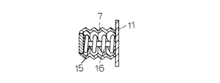
図6に示す脈動吸収体は、樹脂又はゴムから成るベローズ7と、ベローズ7内においてベローズ7とともに伸縮する弾性体を備えており、弾性体が、樹脂又はゴムから成る細い円柱状の成形体15と、この成形体15の外側に同心状に配置したコイルばね16を備えたものとなっている。
The pulsation absorber shown in FIG. 6 includes a
図7に示す脈動吸収体は、樹脂又はゴムから成るベローズ7と、ベローズ7内においてベローズ7とともに伸縮する弾性体を備えており、弾性体が、樹脂又はゴムにコイルばね16をインサート成形して成る複合成形体17を備えたものとなっている。
The pulsation absorber shown in FIG. 7 includes a
上記した図3〜図7に示す脈動吸収体は、図1及び図2に示す流体継手A1,A2に適用することができ、その流体継手において、先の実施例及び参考例と同様の効果を得ることができると共に、とくに、ベローズと、成形体及びコイルばねのうちの少なくとも一方とを組み合わせたものでは、脈動吸収体におけるばね定数の設定の自由度をより一層高めることが可能となる。 The pulsation absorber shown in FIG. 3 to FIG. 7 can be applied to the fluid couplings A1 and A2 shown in FIG. 1 and FIG. 2, and the fluid joint has the same effects as the previous examples and reference examples. In particular, a combination of a bellows and at least one of a molded body and a coil spring can further increase the degree of freedom in setting the spring constant in the pulsation absorber.
なお、図3及び図5〜図7に示した成形体には、図4に示すような発泡成形体を用いることも可能であり、発泡成形体を用いた場合には、発泡率を変えることで任意のばね定数を得ることができ、また、オイル等の流体を含浸させることで成形体の劣化を防止しつつ脈動の吸収機能を調整することも可能である。さらに、図4に示した支持体11の空気孔11aは、上記した実施例及び参考例や後記する参考例にも適用することができる。
In addition, it is also possible to use a foam molded body as shown in FIG. 4 for the molded body shown in FIG. 3 and FIGS. 5 to 7, and when the foam molded body is used, the foaming rate is changed. Thus, an arbitrary spring constant can be obtained, and it is also possible to adjust the function of absorbing pulsation while preventing deterioration of the molded body by impregnating with a fluid such as oil. Furthermore, the
図8は本発明の流体継手のさらに他の参考例を説明する図である。なお、先の実施例と同一の構成部位は、同一符号を付して詳細な説明を省略する。 FIG. 8 is a view for explaining still another reference example of the fluid coupling of the present invention. Note that the same components as those in the previous embodiment are denoted by the same reference numerals and detailed description thereof is omitted.
図示の流体継手A3は、ストレートタイプであって、先の実施例と同様の一方の接続部J1と他方の接続部J2を一体的に備えており、継手本体のほぼ中間に、流体経路5から分岐した緩衝室Fを一体的に備え、緩衝室F内に、流体経路5を流れる燃料の脈動を吸収する脈動吸収体を備えている。
The illustrated fluid coupling A3 is a straight type, and is integrally provided with one connection portion J1 and the other connection portion J2 similar to those of the previous embodiment, and is branched from the
そして、この実施例では、脈動吸収体としてベローズ7を備えている。なお、緩衝室Fは、同緩衝室Fよりも狭められた連通路8を介して流体経路5に連通すると共に、その反対側で開放されており、この開放端部には、先の実施例と同様に、ベローズ7を取付けた支持体11が固定してある。
In this embodiment, a
上記の流体継手A3は、ベローズ7の伸縮により燃料の脈動吸収を行うほか、緩衝室Fがヘルムホルツ型の共鳴室として作用して、燃料の脈動をより一層効率的に吸収することができ、しかも、ストレートタイプの流体経路5に対して直交する方向に分岐する緩衝室Fを設けて、この緩衝室F内に脈動吸収体を配置しているので、燃料の流れを何ら妨げることがなく、燃料の圧力損失が極めて少ないという利点もある。
The fluid coupling A3 absorbs fuel pulsation by expansion and contraction of the
また、上記の流体継手A3は、先の実施例と同様に、小型で且つ部品点数の少ない簡単な構造であるうえに、燃料供給系の軽量化や低コスト化を実現し、スペースが限られたエンジンルーム内のレイアウトにも容易に対処し得るものとなり、さらには、図2〜図7に示す脈動吸収体を適用することも可能である。 In addition, the fluid coupling A3 has a simple structure with a small size and a small number of parts, as in the previous embodiment, and also realizes weight reduction and cost reduction of the fuel supply system, and space is limited. In addition, the layout in the engine room can be easily dealt with, and it is also possible to apply the pulsation absorber shown in FIGS.
図9は、図8に示す流体継手A3に対して、脈動吸収体の他の実施例を説明する図である。図示の脈動吸収体は、樹脂又はゴムから成るダイアフラム18と、ダイアフラム18の変形とともに伸縮する弾性体を備えている。ダイアフラム18は、緩衝室F内を仕切る状態で設けてある。また、弾性体は、コイルばね19であって、ダイアフラム18と支持体11の間に介装してある。
FIG. 9 is a diagram for explaining another embodiment of the pulsation absorber for the fluid coupling A3 shown in FIG. The illustrated pulsation absorber includes a
このような脈動吸収体を備えた流体継手にあっても、先の各実施例と同様の効果を得ることができる。なお、図9に示す脈動吸収体は、図2に示すエルボータイプの流体継手A2に適用することも可能であり、用いる弾性体としては、上記したコイルばね以外に、図2〜図7に示す脈動吸収体の弾性体を適用することができ、例えばダイアフラム18と弾性体(成形体)とを同一材料で一体的に形成することも可能であって、一体成形することで部品点数の削減や低コスト化に貢献し得るものとなる。
Even in the fluid coupling including such a pulsation absorber, the same effects as those of the previous embodiments can be obtained. The pulsation absorber shown in FIG. 9 can also be applied to the elbow type fluid coupling A2 shown in FIG. 2, and the elastic body used is shown in FIGS. An elastic body of a pulsation absorber can be applied. For example, the
A1〜A3 流体継手
F 緩衝室
5 流体経路
7 ベローズ(脈動吸収体)
12 成形体(脈動吸収体の弾性体)
13 中空成形体(脈動吸収体の弾性体)
14 発泡成形体(脈動吸収体の弾性体)
15 成形体(脈動吸収体の弾性体)
16 コイルばね(脈動吸収体の弾性体)
17 複合成形体(脈動吸収体の弾性体)
18 ダイアヤフラム(脈動吸収体)
19 コイルばね(脈動吸収体の弾性体)
A1 to A3 Fluid coupling
12 Molded body (elastic body of pulsation absorber)
13 Hollow molded body (elastic body of pulsation absorber)
14 Foam molding (elastic body of pulsation absorber)
15 Molded body (elastic body of pulsation absorber)
16 Coil spring (elastic body of pulsation absorber)
17 Composite molded body (elastic body of pulsation absorber)
18 Diaphragm (pulsation absorber)
19 Coil spring (elastic body of pulsation absorber)
Claims (4)
Priority Applications (5)
| Application Number | Priority Date | Filing Date | Title |
|---|---|---|---|
| JP2004163141A JP4641387B2 (en) | 2004-06-01 | 2004-06-01 | Fluid coupling |
| EP05011758A EP1602820A3 (en) | 2004-06-01 | 2005-05-31 | Fluid coupling |
| CN200510073189A CN100582546C (en) | 2004-06-01 | 2005-06-01 | Fluid coupling |
| US11/141,384 US20050263198A1 (en) | 2004-06-01 | 2005-06-01 | Fluid coupling |
| US11/941,310 US7665484B2 (en) | 2004-06-01 | 2007-11-16 | Fluid coupling |
Applications Claiming Priority (1)
| Application Number | Priority Date | Filing Date | Title |
|---|---|---|---|
| JP2004163141A JP4641387B2 (en) | 2004-06-01 | 2004-06-01 | Fluid coupling |
Related Child Applications (1)
| Application Number | Title | Priority Date | Filing Date |
|---|---|---|---|
| JP2009294184A Division JP5056838B2 (en) | 2009-12-25 | 2009-12-25 | Fluid coupling |
Publications (2)
| Publication Number | Publication Date |
|---|---|
| JP2005344547A JP2005344547A (en) | 2005-12-15 |
| JP4641387B2 true JP4641387B2 (en) | 2011-03-02 |
Family
ID=34937105
Family Applications (1)
| Application Number | Title | Priority Date | Filing Date |
|---|---|---|---|
| JP2004163141A Expired - Fee Related JP4641387B2 (en) | 2004-06-01 | 2004-06-01 | Fluid coupling |
Country Status (4)
| Country | Link |
|---|---|
| US (2) | US20050263198A1 (en) |
| EP (1) | EP1602820A3 (en) |
| JP (1) | JP4641387B2 (en) |
| CN (1) | CN100582546C (en) |
Families Citing this family (46)
| Publication number | Priority date | Publication date | Assignee | Title |
|---|---|---|---|---|
| AT503660B1 (en) * | 2006-06-13 | 2007-12-15 | Bosch Gmbh Robert | DEVICE FOR INJECTING FUEL IN THE COMBUSTION ENGINE OF AN INTERNAL COMBUSTION ENGINE |
| DE102007003724A1 (en) * | 2007-01-25 | 2008-07-31 | Hydac Technology Gmbh | Pressure vessel, in particular hydraulic accumulator |
| JP4782030B2 (en) * | 2007-01-31 | 2011-09-28 | 川崎重工業株式会社 | Engine and motorcycle equipped with the engine |
| US20100178182A1 (en) * | 2009-01-09 | 2010-07-15 | Simmons Tom M | Helical bellows, pump including same and method of bellows fabrication |
| US8636484B2 (en) * | 2009-01-09 | 2014-01-28 | Tom M. Simmons | Bellows plungers having one or more helically extending features, pumps including such bellows plungers, and related methods |
| JP5528838B2 (en) * | 2010-02-05 | 2014-06-25 | 本田技研工業株式会社 | Connector for fuel piping |
| DE102010030627A1 (en) * | 2010-06-29 | 2011-12-29 | Robert Bosch Gmbh | Pulsation damper element for a fluid pump and associated fluid pump |
| EP2610303B1 (en) * | 2010-08-25 | 2016-07-20 | Daikin Industries, Ltd. | Fluoro rubber molding with complex shape |
| US11054066B2 (en) | 2010-08-25 | 2021-07-06 | Daikin Industries, Ltd. | Hose |
| DE102010040612A1 (en) * | 2010-09-13 | 2012-03-15 | Siemens Aktiengesellschaft | Hydraulic temperature compensator and hydraulic lift transmitter |
| US9103395B2 (en) | 2012-01-20 | 2015-08-11 | Xilinmen Furniture Co., Ltd. | Elasticity-adjustable air pressure spring |
| US8757668B2 (en) * | 2012-02-29 | 2014-06-24 | Ti Automotive (Fuldabruck) Gmbh | Connector with pressure equalization |
| US20140041635A1 (en) * | 2012-08-09 | 2014-02-13 | GM Global Technology Operations LLC | Fuel rail connector |
| JP5595457B2 (en) * | 2012-09-05 | 2014-09-24 | 東海ゴム工業株式会社 | connector |
| CN103410644B (en) * | 2013-07-10 | 2015-10-28 | 奇瑞汽车股份有限公司 | A kind of fuel damper and apply the oil passage connection structure of this buffer |
| US9874074B2 (en) * | 2013-10-17 | 2018-01-23 | Baker Hughes, A Ge Company, Llc | Water tight and gas tight flexible fluid compensation bellow |
| FR3012849B1 (en) * | 2013-11-04 | 2018-06-01 | Nobel Plastiques | DAMPING DEVICE FOR PULSATIONS. |
| JP6649256B2 (en) | 2013-12-09 | 2020-02-19 | デイコ アイピー ホールディングス, エルエルシーDayco Ip Holdings, Llc | Engine system noise attenuation unit |
| KR20150102529A (en) * | 2014-02-28 | 2015-09-07 | 한온시스템 주식회사 | A discharge port connector of a compressor |
| KR102224028B1 (en) | 2014-05-30 | 2021-03-05 | 데이코 아이피 홀딩스 엘엘시 | Vacuum creation system having an ejector, pneumatic control valve and optionally an aspirator |
| CN104329533A (en) * | 2014-09-28 | 2015-02-04 | 无锡金顶石油管材配件制造有限公司 | Turbo buffering petroleum pipeline |
| JP2016075310A (en) * | 2014-10-03 | 2016-05-12 | 住友理工株式会社 | Connector and method of manufacturing the same |
| JP6243834B2 (en) * | 2014-12-22 | 2017-12-06 | ヤンマー株式会社 | Fuel supply device for internal combustion engine |
| DE102015218223A1 (en) * | 2015-09-23 | 2017-03-23 | Robert Bosch Gmbh | Pressure pulsation damper for a fuel injection system as well as fuel injection system |
| GB201520677D0 (en) * | 2015-11-24 | 2016-01-06 | Delphi Internat Operations Luxembourg S À R L | High pressure fuel pump |
| CN105443909A (en) * | 2015-12-03 | 2016-03-30 | 重庆互通管道技术设备有限公司 | Damping bent pipe |
| US10206312B2 (en) | 2015-12-21 | 2019-02-12 | Dell Products, L.P. | Liquid cooled rack information handling system having storage drive carrier for leak containment and vibration mitigation |
| US10156873B2 (en) | 2015-12-21 | 2018-12-18 | Dell Products, L.P. | Information handling system having fluid manifold with embedded heat exchanger system |
| US10010013B2 (en) | 2015-12-21 | 2018-06-26 | Dell Products, L.P. | Scalable rack-mount air-to-liquid heat exchanger |
| US10064314B2 (en) | 2015-12-21 | 2018-08-28 | Dell Products, L.P. | Runtime service of liquid cooled servers operating under positive hydraulic pressure without impacting component performance |
| US9795065B2 (en) * | 2015-12-21 | 2017-10-17 | Dell Products, L.P. | Integrated air-spring for hydraulic force damping of a rigid liquid cooling subsystem |
| US10146231B2 (en) | 2015-12-21 | 2018-12-04 | Dell Products, L.P. | Liquid flow control based upon energy balance and fan speed for controlling exhaust air temperature |
| US9839164B2 (en) | 2015-12-21 | 2017-12-05 | Dell Products, L.P. | Rack information handling system having modular liquid distribution (MLD) conduits |
| FR3057034A1 (en) * | 2016-10-03 | 2018-04-06 | Peugeot Citroen Automobiles Sa | DAMPING DEVICE FOR PULSATION OF A FUEL CIRCUIT |
| IT201600108035A1 (en) * | 2016-10-26 | 2018-04-26 | Hutchinson Srl | Damper for a fluid line, in particular a fuel line for an internal combustion engine |
| CN108071533B (en) * | 2016-11-15 | 2022-08-12 | 福特环球技术公司 | Fuel pressure pulse damping device and fuel system |
| FR3060533A1 (en) * | 2016-12-19 | 2018-06-22 | Safran Aircraft Engines | ACCUMULATOR ON AN AIRCRAFT FUEL LINE |
| FR3074541B1 (en) * | 2017-12-01 | 2019-10-18 | Safran Aircraft Engines | ACCUMULATOR INTEGRATED WITH A FUEL PIPING |
| CN108678878A (en) * | 2018-08-07 | 2018-10-19 | 天津开发区天盈企业有限公司 | A kind of oil pipe pipe nipple |
| WO2020065662A1 (en) * | 2018-09-24 | 2020-04-02 | Indius Medical Technologies Private Limited | Miniature pressure compensating device |
| JP7300299B2 (en) * | 2019-04-03 | 2023-06-29 | 株式会社十川ゴム | Faucet damper structure, faucet provided with faucet damper structure, and method for reducing sound in faucet |
| CN111140722B (en) * | 2019-05-07 | 2022-04-12 | 杭州精进科技有限公司 | Fluid conveying system and fluid pulse absorption device |
| CH716345B1 (en) * | 2019-06-24 | 2023-02-28 | Schlumpf Innovations Gmbh | pulsation dampener. |
| FR3098867A1 (en) | 2019-07-19 | 2021-01-22 | Psa Automobiles Sa | QUICK CONNECTOR FOR MOTOR VEHICLE FUEL WITH PULSATION DAMPER |
| US11692537B2 (en) | 2021-01-11 | 2023-07-04 | Comet-ME Ltd. | Method and system for damping flow pulsation |
| DE102021113244A1 (en) * | 2021-05-21 | 2022-11-24 | Naber Holding Gmbh & Co. Kg | Downdraft Element and Arrangement |
Family Cites Families (42)
| Publication number | Priority date | Publication date | Assignee | Title |
|---|---|---|---|---|
| US2904077A (en) * | 1955-11-28 | 1959-09-15 | Rheinstahl Siegener Eisenbahnb | Shock absorbers |
| US2829669A (en) * | 1956-06-13 | 1958-04-08 | Anthony J Luzynski | Antiknock fitting |
| US3001268A (en) * | 1958-04-02 | 1961-09-26 | Greer Hydraulics Inc | Method of assembling pressure accumulator |
| US3237715A (en) * | 1959-09-15 | 1966-03-01 | Joseph J Mascuch | Flexible hose structures |
| US3076479A (en) * | 1960-11-02 | 1963-02-05 | Ottung Kai | Expansion means for self-contained liquid circulating systems |
| US3159182A (en) * | 1963-09-11 | 1964-12-01 | Melville F Peters | Bellows sealing and securing device |
| US3534884A (en) * | 1968-07-01 | 1970-10-20 | Goodyear Tire & Rubber | Pressurizable container and method of preparation |
| US3714964A (en) * | 1968-10-24 | 1973-02-06 | Factory Mutual Res Corp | Double rate flow controller |
| US4177023A (en) * | 1975-02-25 | 1979-12-04 | Toyota Jidosha Kogyo Kabushiki Kaisha | Pneumatic system for smoothing discharge pressure from air |
| DE3152860A1 (en) * | 1981-05-14 | 1983-07-14 | Robert Bosch Gmbh, 7000 Stuttgart | Damper element |
| JPS5872795A (en) | 1981-10-23 | 1983-04-30 | 日産自動車株式会社 | Pressure pulsation removing device for fuel piping |
| US4527580A (en) * | 1983-11-25 | 1985-07-09 | Sundstrand Corporation | Volume control device |
| CN85102290B (en) | 1985-04-01 | 1987-12-23 | 西安交通大学 | Impulse-eliminator using travelling wave tube |
| US4903486A (en) * | 1987-12-01 | 1990-02-27 | Larry K. Goodman | Performance responsive muffler for internal combustion engines |
| CN88210181U (en) | 1988-02-13 | 1988-11-02 | 赵振勇 | Anticorrosive pressure sensor |
| JPH0290359U (en) * | 1988-12-28 | 1990-07-18 | ||
| JPH02286995A (en) | 1989-04-27 | 1990-11-27 | Hitachi Metals Ltd | Pressure container |
| CN2092622U (en) | 1991-05-07 | 1992-01-08 | 深圳四方机械电子有限公司 | Shock absorber for hydraulic pipelines |
| DE4318553C2 (en) * | 1993-06-04 | 1995-05-18 | Daimler Benz Ag | Adaptive hydropneumatic pulsation damper |
| JPH07239160A (en) | 1994-02-28 | 1995-09-12 | Sanyo Electric Co Ltd | Pressure buffering device |
| JPH084615A (en) * | 1994-06-21 | 1996-01-09 | Toyota Motor Corp | Pressure pulsation decreasing damper |
| US5415201A (en) * | 1994-06-27 | 1995-05-16 | The United States Of America As Represented By The Secretary Of The Navy | Multi-stage fluid flow control device |
| JPH08261098A (en) * | 1995-03-24 | 1996-10-08 | Toyoda Gosei Co Ltd | Fuel pressure pulsation damper |
| JPH08261097A (en) | 1995-03-24 | 1996-10-08 | Toyoda Gosei Co Ltd | Fuel pressure pulsation damper |
| JP3206361B2 (en) * | 1995-04-13 | 2001-09-10 | 三菱自動車工業株式会社 | Fuel supply device |
| JP3292017B2 (en) | 1996-01-16 | 2002-06-17 | トヨタ自動車株式会社 | Fuel supply system for V-type engine |
| JP3750754B2 (en) * | 1996-05-14 | 2006-03-01 | 株式会社デンソー | Fuel supply device for internal combustion engine |
| US5638868A (en) * | 1996-06-05 | 1997-06-17 | Valcor Engineering | Accumulator |
| US5740837A (en) * | 1996-11-05 | 1998-04-21 | Chiang; Swea Tong | Means for automatically regulating water pressure in water pipe |
| CN2293822Y (en) | 1997-05-23 | 1998-10-07 | 杨德林 | Pulsation resistant pressure gage |
| US5845621A (en) * | 1997-06-19 | 1998-12-08 | Siemens Automotive Corporation | Bellows pressure pulsation damper |
| US6098663A (en) * | 1998-04-15 | 2000-08-08 | Larsen; Richard R. | High impact bellows |
| US6076557A (en) * | 1998-06-12 | 2000-06-20 | Senior Engineering Investments Ag | Thin wall, high pressure, volume compensator |
| JP2000073907A (en) | 1998-09-02 | 2000-03-07 | Aisan Ind Co Ltd | Fuel distribution device for internal combustion engine |
| JP2000213434A (en) * | 1999-01-20 | 2000-08-02 | Toyoda Gosei Co Ltd | Fuel pressure regulating device |
| US6412476B1 (en) * | 2000-08-02 | 2002-07-02 | Ford Global Tech., Inc. | Fuel system |
| US6390132B1 (en) * | 2000-12-07 | 2002-05-21 | Caterpillar Inc. | Fluid stream pulse damper |
| US6405994B1 (en) * | 2000-12-22 | 2002-06-18 | Taiwan Semiconductor Manufacturing Co., Ltd | Flow control valve incorporating an inflatable bag |
| CN1348059A (en) | 2001-11-27 | 2002-05-08 | 董乃强 | Environment protecting power economizer for diesel oil internal combustion engine |
| US6672286B2 (en) * | 2001-12-14 | 2004-01-06 | Siemens Automotive Corporation | Corrugated fuel rail damper |
| JP2004137977A (en) * | 2002-10-18 | 2004-05-13 | Usui Kokusai Sangyo Kaisha Ltd | Pulsing reduction system of fuel pipe system |
| CN2591383Y (en) | 2002-12-24 | 2003-12-10 | 廖换彩 | In-pipe water hammer arrester |
-
2004
- 2004-06-01 JP JP2004163141A patent/JP4641387B2/en not_active Expired - Fee Related
-
2005
- 2005-05-31 EP EP05011758A patent/EP1602820A3/en not_active Withdrawn
- 2005-06-01 US US11/141,384 patent/US20050263198A1/en not_active Abandoned
- 2005-06-01 CN CN200510073189A patent/CN100582546C/en not_active Expired - Fee Related
-
2007
- 2007-11-16 US US11/941,310 patent/US7665484B2/en not_active Expired - Fee Related
Also Published As
| Publication number | Publication date |
|---|---|
| US20050263198A1 (en) | 2005-12-01 |
| CN1704637A (en) | 2005-12-07 |
| EP1602820A3 (en) | 2011-09-28 |
| CN100582546C (en) | 2010-01-20 |
| US20080067805A1 (en) | 2008-03-20 |
| EP1602820A2 (en) | 2005-12-07 |
| US7665484B2 (en) | 2010-02-23 |
| JP2005344547A (en) | 2005-12-15 |
Similar Documents
| Publication | Publication Date | Title |
|---|---|---|
| JP4641387B2 (en) | Fluid coupling | |
| US6948479B1 (en) | Inline pulsation damper system | |
| KR100981355B1 (en) | Fuel delivery pipe | |
| US20060163785A1 (en) | Hydraulically damped body mount with bolt-through construction | |
| JP5056838B2 (en) | Fluid coupling | |
| JP2002505401A (en) | Fuel supply system for internal combustion engine | |
| WO2009124185A2 (en) | A construction vehicle cab suspension mount | |
| JPH10315790A (en) | Hydraulic torque restraining system | |
| JP4906768B2 (en) | Vibration isolator | |
| US20070222129A1 (en) | Apparatus for isolating vibration | |
| US7703443B2 (en) | Fuel supply devices | |
| JP5528838B2 (en) | Connector for fuel piping | |
| JPH08261097A (en) | Fuel pressure pulsation damper | |
| JP2004183812A (en) | Hydraulic coupling | |
| JPH08261098A (en) | Fuel pressure pulsation damper | |
| JP2000213434A (en) | Fuel pressure regulating device | |
| JP4148861B2 (en) | Fuel delivery pipe | |
| JPH09257186A (en) | Joint for pipe with orifice | |
| CN116457593A (en) | Hydraulic bushing with internal damper | |
| JPH08261101A (en) | Fuel pressure pulsation damping device | |
| JP4236799B2 (en) | Fuel supply piping | |
| JP2003307164A (en) | Fuel delivery pipe | |
| KR102387707B1 (en) | Device for reducing delivery pipe pulsation of fuel system | |
| JP3997512B2 (en) | Fuel delivery pipe | |
| KR102624866B1 (en) | Purge control solenoid valve structure |
Legal Events
| Date | Code | Title | Description |
|---|---|---|---|
| A621 | Written request for application examination |
Free format text: JAPANESE INTERMEDIATE CODE: A621 Effective date: 20070425 |
|
| A131 | Notification of reasons for refusal |
Free format text: JAPANESE INTERMEDIATE CODE: A131 Effective date: 20080925 |
|
| A977 | Report on retrieval |
Free format text: JAPANESE INTERMEDIATE CODE: A971007 Effective date: 20080925 |
|
| A521 | Written amendment |
Free format text: JAPANESE INTERMEDIATE CODE: A523 Effective date: 20081120 |
|
| A131 | Notification of reasons for refusal |
Free format text: JAPANESE INTERMEDIATE CODE: A131 Effective date: 20090115 |
|
| A521 | Written amendment |
Free format text: JAPANESE INTERMEDIATE CODE: A523 Effective date: 20090312 |
|
| A131 | Notification of reasons for refusal |
Free format text: JAPANESE INTERMEDIATE CODE: A131 Effective date: 20090521 |
|
| A521 | Written amendment |
Free format text: JAPANESE INTERMEDIATE CODE: A523 Effective date: 20090717 |
|
| A02 | Decision of refusal |
Free format text: JAPANESE INTERMEDIATE CODE: A02 Effective date: 20090929 |
|
| A521 | Written amendment |
Free format text: JAPANESE INTERMEDIATE CODE: A523 Effective date: 20091225 |
|
| A911 | Transfer of reconsideration by examiner before appeal (zenchi) |
Free format text: JAPANESE INTERMEDIATE CODE: A911 Effective date: 20100105 |
|
| A912 | Removal of reconsideration by examiner before appeal (zenchi) |
Free format text: JAPANESE INTERMEDIATE CODE: A912 Effective date: 20100205 |
|
| A521 | Written amendment |
Free format text: JAPANESE INTERMEDIATE CODE: A523 Effective date: 20101013 |
|
| A521 | Written amendment |
Free format text: JAPANESE INTERMEDIATE CODE: A523 Effective date: 20101026 |
|
| A01 | Written decision to grant a patent or to grant a registration (utility model) |
Free format text: JAPANESE INTERMEDIATE CODE: A01 |
|
| A61 | First payment of annual fees (during grant procedure) |
Free format text: JAPANESE INTERMEDIATE CODE: A61 Effective date: 20101129 |
|
| R150 | Certificate of patent or registration of utility model |
Free format text: JAPANESE INTERMEDIATE CODE: R150 |
|
| FPAY | Renewal fee payment (event date is renewal date of database) |
Free format text: PAYMENT UNTIL: 20131210 Year of fee payment: 3 |
|
| LAPS | Cancellation because of no payment of annual fees |