JP4636741B2 - Image processing apparatus and three-dimensional shape display program - Google Patents
Image processing apparatus and three-dimensional shape display program Download PDFInfo
- Publication number
- JP4636741B2 JP4636741B2 JP2001206843A JP2001206843A JP4636741B2 JP 4636741 B2 JP4636741 B2 JP 4636741B2 JP 2001206843 A JP2001206843 A JP 2001206843A JP 2001206843 A JP2001206843 A JP 2001206843A JP 4636741 B2 JP4636741 B2 JP 4636741B2
- Authority
- JP
- Japan
- Prior art keywords
- data
- distance
- gravity
- center
- dimensional shape
- Prior art date
- Legal status (The legal status is an assumption and is not a legal conclusion. Google has not performed a legal analysis and makes no representation as to the accuracy of the status listed.)
- Expired - Fee Related
Links
Images


Classifications
-
- G—PHYSICS
- G06—COMPUTING; CALCULATING OR COUNTING
- G06T—IMAGE DATA PROCESSING OR GENERATION, IN GENERAL
- G06T17/00—Three dimensional [3D] modelling, e.g. data description of 3D objects
Landscapes
- Physics & Mathematics (AREA)
- Engineering & Computer Science (AREA)
- Computer Graphics (AREA)
- Geometry (AREA)
- Software Systems (AREA)
- General Physics & Mathematics (AREA)
- Theoretical Computer Science (AREA)
- Processing Or Creating Images (AREA)
- Image Generation (AREA)
Description
【0001】
【発明の属する技術分野】
本発明は、画像処理装置および立体形状表示プログラムに関し、より特定的には、特徴的なデータ構造を用いて立体形状を表示する画像処理装置、および当該装置で実行されるプログラムに関する。
【0002】
【従来の技術】
周知のように、グラフィック分野においては、物体の移動や回転等の様々な表現が容易に可能になってきている。その中でも、ゲームの分野においては、キャラクタがゲーム実行のために移動可能な領域(以下、ゲームフィールドという)を、自由に移動できる表現が用いられてきている。
一般に、このゲームフィールドは、二次元平面で表され、平面上に形成される突起物等の物体は、平面座標の属性データとして高さ情報が与えられることによって表示される。キャラクタがゲームフィールドを移動する場合、移動先の平面座標の属性データを参照してキャラクタの高さ位置を制御することで、キャラクタが物体の表面に沿って移動できるようにしている。
【0003】
【発明が解決しようとする課題】
ところで近年、ゲームフィールドを、例えば地球のような閉曲面の立体で表示して、キャラクタがこの立体表面上を縦横無尽に移動できるように表現することが望まれている。すなわち、ある地点から真っ直ぐに進み続けると、同一地点に再び戻ってくるようなゲームフィールド表現を可能にすることである。
しかしながら、上述した従来の画像処理技術では、ゲームフィールドを二次元平面で表示するため、三次元の立体を直接的に表示することができない。なお、簡単な立体(六面体等)については、複数の二次元平面を繋ぎ合わせて擬似的に表示する方法も考えられるが、この方法の場合、キャラクタが移動するたびに全ての二次元平面の各データを対象に処理しなくてはならない。このため、結果を得るまでの処理時間が増大することに加え、処理時間にばらつきが生じるので、この方法は現実的ではない。
【0004】
それ故に、本発明の目的は、特徴的なデータ構造を用いて複雑な三次元の立体(ゲームフィールド、キャラクタ(敵キャラクタや建物等))を表示できると共に、キャラクタ等の特定点と立体面との位置関係を容易に把握することが可能な画像処理装置および当該装置で実行される立体形状表示プログラムを提供することである。
【0005】
【課題を解決するための手段および発明の効果】
第1の発明は、複数の多角形で構成される所望の立体形状を表示するための画像データを出力する画像処理装置であって、
空間上の任意の点を重心とし、各面が複数の多角形に分割された正多面体を規定し、当該重心から当該複数の多角形の各頂点に向かう方向を示すベクトルデータおよび当該重心と所望の立体形状の複数の多角形の各頂点との距離を設定するための距離データを記憶する記憶部、
記憶部からベクトルデータおよび距離データを読み出す読出部、および
重心から、読出部によって読み出されたベクトルデータに基づく方向で、距離データに基づく距離にある点を、所望の立体形状の複数の多角形の各頂点として、所望の立体形状を画像表示するための画像データを出力する画像データ出力部を備える。
【0006】
上記のように、第1の発明によれば、正多面体の複数の多角形の頂点毎にベクトルデータおよび距離データを持たせ、その距離データを任意に変更させることで、様々な立体形状を簡単に表示することができる。
【0007】
第2の発明は、第1の発明に従属する発明であって、
正多面体の各面を分割している複数の多角形は、それぞれ大きさおよび形状が同じであることを特徴とする。
【0008】
この第2の発明のように、複数の多角形の大きさおよび形状を全て同じにすることで、データ管理が容易になる。
【0009】
第3の発明は、第1および第2の発明に従属する発明であって、
正多面体が、正八面体であることを特徴とする
【0010】
この第3の発明のように、正多面体を正八面体にすれば、正多面体を展開させたときに正方形を形成することができるので、データ管理が容易になる。
【0011】
第4の発明は、第1〜第3の発明に従属する発明であって、
他の物体の重心からの距離と、所望の立体形状上の接触処理対象となる多角形の重心からの距離とに基づいて、当該所望の立体形状と当該他の物体との接触判定を行う接触判定部をさらに備える。
【0012】
上記のように、第4の発明によれば、どんな複雑な立体形状であっても、特定の計算によってある空間座標値から処理対象となる多角形のデータを得ることができる。従って、ある空間座標に存在する物体と処理対象となる多角形との接触判定を容易に行うことが可能となる。
【0013】
第5の発明は、複数の多角形で構成される所望の立体形状を表示するための画像データを出力するために、空間上の任意の点を重心とし、各面が複数の多角形に分割された正多面体を規定し、重心から複数の多角形の各頂点に向かう方向を示すベクトルデータおよび重心と所望の立体形状の複数の多角形の各頂点との距離を設定するための距離データを記憶する記憶部からデータ読み出し可能なコンピュータ装置によって実行されるプログラムであって、
記憶部からベクトルデータおよび距離データを読み出すステップ、および
重心から、読み出されたベクトルデータに基づく方向で、距離データに基づく距離にある点を、所望の立体形状の複数の多角形の各頂点として、所望の立体形状を画像表示するための画像データを出力するステップを含む。
【0014】
上記のように、第5の発明によれば、正多面体の複数の多角形の頂点毎にベクトルデータおよび距離データを持たせ、その距離データを任意に変更させることで、様々な立体形状を簡単に表示することができる。
【0015】
第6の発明は、第5の発明に従属する発明であって、
正多面体の各面を分割している複数の多角形は、それぞれ大きさおよび形状が同じであることを特徴とする。
【0016】
この第6の発明のように、複数の多角形の大きさおよび形状を全て同じにすることで、データ管理が容易になる。
【0017】
第7の発明は、第5および第6の発明に従属する発明であって、
正多面体が、正八面体であることを特徴とする。
【0018】
この第7の発明のように、正多面体を正八面体にすれば、正多面体を展開させたときに正方形を形成することができるので、データ管理が容易になる。
【0019】
第8の発明は、第5〜第7の発明に従属する発明であって、
他の物体の重心からの距離と、所望の立体形状上の接触処理対象となる多角形の重心からの距離とに基づいて、当該所望の立体形状と当該他の物体との接触判定を行うステップをさらに含む。
【0020】
第9の発明は、第8の発明に従属する発明であって、
接触判定を行うステップは、
他の物体の空間座標値の符号に基づいて、接触処理対象となる多角形が含まれる正多面体の面領域を選択するステップ、
距離データから得られる平面方程式を用いて、選択された面領域の中から接触処理対象となる多角形を特定するステップ、および
特定された多角形の重心からの距離と、他の物体の重心からの距離とを比較し、当該他の物体と所望の立体形状との接触を判断するステップからなる。
【0021】
上記のように、第8および第9の発明によれば、どんな複雑な立体形状であっても、特定の計算によってある空間座標値から処理対象となる多角形のデータを得ることができる。従って、ある空間座標に存在する物体と処理対象となる多角形との接触判定を容易に行うことが可能となる。これにより、キャラクタが立体表面を連続して移動する等の場合であっても、高速に安定した処理を行うことが可能となる。また、複雑な形状との接触判定を行うソフトウエアの開発が容易に実現できる。
【0022】
第10の発明は、コンピュータ装置によって実行され、複数の多角形で構成される所望の立体形状を表示するためのプログラムおよびデータを記録する記録媒体であって、
空間上の任意の点を重心とし、各面が複数の多角形に分割された正多面体を規定し、重心から当該複数の多角形の各頂点に向かう方向を示すベクトルデータ、
重心と所望の立体形状の複数の多角形の各頂点との距離を設定するための距離データ、
記憶部からベクトルデータおよび距離データを読み出すためのプログラム、および
重心から、読み出されたベクトルデータに基づく方向で、距離データに基づく距離にある点を、所望の立体形状の複数の多角形の各頂点として、所望の立体形状を画像表示するための画像データを出力するためのプログラムを記録する。
【0023】
【発明の実施の形態】
本発明が提供する画像処理装置は、ポリゴンによる画像表示を必要とするグラフィックシステムやゲーム機器等に用いられ、それらを構成するCPUやメモリ等と協働して特徴的な処理を行うことで実現される。以下、本発明が提供する画像処理装置および当該装置で実行される立体形状表示プログラムを、図1〜図14を参照して説明する。
【0024】
(本発明を実現させるためのシステム環境)
図1に、本発明の立体形状表示プログラムを実行する画像処理装置を含むビデオゲームシステムの構成例を示す。図1において、ビデオゲームシステムは、メインプロセッサ41、コプロセッサ42、メモリ43およびドライブユニット44を備えるメインユニットと、ゲームコントローラ46と、表示部45と、ゲームディスク47とで構成される。
【0025】
コプロセッサ42は、バス制御を行うためのバス制御回路と、ポリゴンの座標変換や陰影処理等を行うための信号プロセッサと、ポリゴンデータを表示すべき画像にラスタライズしかつフレームメモリに記憶可能なデータ形式(ドットデータ)に変換するための描画プロセッサとを含む(いずれも図示せず)。コプロセッサ42には、ゲームディスク47を駆動させるドライブユニット44とメモリ43とが接続される。また、コプロセッサ42には、メインプロセッサ41によって処理された音声信号および映像信号をそれぞれ出力するためのデジタル/アナログ変換器(図示せず)を介して、表示部45が接続される。また、コプロセッサ42には、ゲームコントローラ46が接続される。
バス制御回路は、バスを介してメインプロセッサ41からパラレル信号で与えられたコマンドをシリアル信号に変換して、ゲームコントローラ46に供給する。また、バス制御回路は、ゲームコントローラ46からシリアル信号で与えられたコマンドをパラレル信号に変換して、メインプロセッサ41へ出力する。ゲームコントローラ46から入力される操作状態を示すデータは、メインプロセッサ41によって処理されたり、メモリ43に一時記憶される等の処理が行われる。ゲームディスク47に格納されているプログラムおよびメモリ43に格納されているプログラムは、ゲームコントローラ46から入力される操作に応じて、メインプロセッサ41およびコプロセッサ42で実行処理される。実行された結果は、コプロセッサ42によって表示部45の画面上に表示される。
【0026】
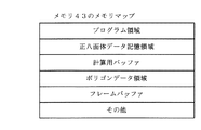
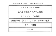
図1において、本発明の立体形状表示プログラムは、メモリ43およびゲームディスク47に格納され、コプロセッサ42内で実行される。メモリ43には、図2のメモリマップで示されるプログラムおよびデータが格納される。また、ゲームディスク47は、DVD等の記録媒体であって、図3のメモリマップで示されるプログラムおよびデータが格納される。
【0027】
メモリ43において、プログラム領域には、ビデオゲームメインユニットを動作させるための基本的なシステムプログラムが格納されている。正八面体データ記憶領域には、後述する基本立体形状である正八面体のデータが格納される。計算用バッファは、各種計算に用いられるバッファである。ポリゴンデータ領域には、1枚のフレーム画像を構成するために必要なポリゴンデータの情報が格納される。フレームバッファには、1フレームの画像が格納される。
ゲームディスク47において、メインプログラム領域には、ゲームを動作させる基本的なプログラムが格納されている。正八面体処理プログラム領域には、後述する正八面体を基本立体形状とする各処理を実行させるためのプログラムが格納されている。その他のプログラム領域には、メインプログラム以外のプログラムが格納されている。画像データ領域には、正八面体のデータや、ゲームのグラフィック表示に必要なポリゴンおよびテクスチャ等に関する様々なデータが格納されている。音データ領域には、ゲームの音表現に関する様々なデータが格納されている。
【0028】
(格納される立体形状データの構造)
次に、図4〜図7を用いて、本発明の一実施形態に係る立体形状表示プログラムで用いられるデータ構造を説明する。
【0029】
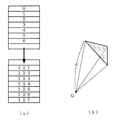
本発明では、三次元空間の任意の点を原点とする特定の座標系において、重心Gを原点とする正八面体を、様々な立体形状を表示するための基本立体形状として用いる(図4(a))。この特定の座標系は、原点(重心G)から正八面体の各頂点に向かって放射される放射線(原点から各頂点方向を示すベクトル)が座標軸として設定されており、この各々の座標軸は、その軸上にある正八面体の頂点の移動にそれぞれ用いられる。また、この正八面体の8つの平面は、それぞれ予め複数の三角形の領域に細分化されている。正八面体では、細分化される三角形が正三角形となる。この三角形の各頂点も、原点(重心G)から放射されるそれぞれの放射線(座標軸)上に位置するように設定されている。なお、図4の例では、1つの平面の各辺をそれぞれ4等分する16個の三角形に分割しているが、他の数に分割してもかまわない。
なお、特定の座標系の原点がゲームフィールド(直交座標系)の原点と異なる場合、特定の座標系の原点をゲームフィールドの原点から相対的に判断する必要がある。
【0030】
正八面体の各平面を分割している三角形には、それぞれ固有の識別番号が設定される。この識別番号は、次のようにして設定される。
まず、正八面体のY座標が負値である4つの平面を正値側へそれぞれ展開し(図4(b)の実線矢印)、正八面体の8つの平面を上方向(同図の白抜き矢印方向)から見た二次元平面(図5(a))で表す。そして、この二次元平面で表された各三角形(直角二等辺三角形となる)に対して、図5(b)のように左上から右下に向かって順番に識別番号(0〜127)を与える。この識別番号は、メモリ等の記憶装置内のアドレスを特定できる情報である。この二次元平面では、縦横の線で囲まれるマス目がXZ座標の値によって区切られ、マス目内の斜線がY座標の値によって区切られていることが分かる。一方、メモリ内には、予め識別番号毎にデータ格納領域が確保されており(図6(a))、そこには原点(重心G)から三角形の各頂点までの距離d(図6(b))、三角形の平面方程式および表面の模様等のデータが格納されている。なお、三角形の平面方程式は、距離dから求めることも可能である。距離dから三角形の平面方程式を求めるようにすれば、格納するデータ量が少なくて済み、距離dの大きさを自在に変化させる場合に有利となる。
これにより、正八面体を構成する各三角形に関するメモリ内のデータを、識別番号を介して参照することが可能となる。
【0031】
このように、本発明では、基本となる正八面体を構成する三角形毎に、その三角形を表示するためのデータがそれぞれ格納されているので、このデータを任意に変更することで様々な形状の立体を簡単に表示することができる。すなわち、本発明では、平面の各頂点が重心からの距離dで与えられる特定の座標系を用いて、立体形状を表示している。このため、正八面体を構成する三角形の各頂点を、座標軸上を距離dに従ってそれぞれ移動させるだけで、正八面体を簡単に変形することができるので、様々な立体表示が容易に可能になるのである。例えば、原点から全ての三角形の各頂点までの距離を同じにすれば、球体に近い立体を表示することができる(図7)。
【0032】
(立体形状表示プログラムの実行手順)
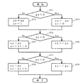
次に、図8を参照して、上述したデータ構造を用いた立体形状表示プログラムが、図1に示すビデオゲームシステム上でどのように実行され、作成する立体(作成立体)がディスプレイの画面に表示されるのかを説明する。
【0033】
始めに、電源投入時に動作するプログラムによって初期設定が行われる(ステップS11)。この初期設定では、ゲームディスク47がセットされているか否かやゲームコントローラ46が接続されているか否か等が検出される。初期設定が完了すると、ゲームディスク47からメモリ43へ必要なデータが転送される(ステップS12)。次に、メインプロセッサ41が、メモリ43のプログラム領域に記憶されている立体作成プログラムの実行を開始する(ステップS13)。続いて、メインプロセッサ41が、メモリ43の正八面体データ記憶領域から、基本立体の重心座標、基本三角形の各頂点座標および距離データを読み出し(ステップS14)、これらの座標およびデータから作成立体の各頂点座標を計算する(ステップS15)。そして、メインプロセッサ41が、作成立体の各頂点座標を、メモリ43のポリゴンデータ領域に転送する(ステップS16)。
この後、ゲームシステムでは、作成立体以外のその他のキャラクタの表示処理や(ステップS17)、後述する作成立体とその他のキャラクタとの接触判定処理や(ステップS18)、キャラクタの移動や攻撃処理等のその他のゲームに関する処理が(ステップS19)、必要に応じて行われる。
次に、コプロセッサ42が、メモリ43に記憶された各頂点座標に基づいてポリゴンを作成し、そのポリゴンにテクスチャーを貼り付けることにより表示部45に表示するための画像データを作成し、その画像データをメモリ43のフレームバッファに記憶させる(ステップS20)。最後に、コプロセッサ42が、フレームバッファの画像データに基づいて、表示部45に画像信号を出力する(ステップS21)。上記ステップS13〜S21の処理は、ゲームが終了するまで繰り返して行われる(ステップS22)。
【0034】
(任意の点と立体形状との位置関係判断)
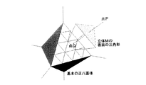
次に、図9〜図14を用いて、上述した立体形状データで表示される立体Mと空間のある任意の点P(px,py,pz)との、位置関係を判断する手法を説明する。この立体Mと点Pの関係としては、例えば、立体M=地面,点P=キャラクタの足の裏、立体M=ビル,点P=キャラクタのお腹、立体M=サーカスのオートバイがその中を走行する球体,点P=オートバイ、等が考えられる。
【0035】
上述した立体M平面上の細分化された三角形の内、空間の点Pと位置関係を判断すべき三角形は、点Pを原点に向かって正八面体上に投影した点Qの位置から特定される(図9)。そして、その特定された三角形の現在の位置データから、立体M表面の平面方程式を求めることができる。そこで、本発明では、以下のように位置関係の判断を行う。
【0036】
最初に、基本立体形状である正八面体の8つの平面のどの平面において、点Pとの位置関係判断処理を行うべきかを決定する。
この決定は、次のようにして行われる。まず、正八面体の8つの平面には、図10に示すようにエリア番号(0〜7)がそれぞれ設定される。図10の例では、X座標値の正負でエリア番号の値が1つ、Y座標値の正負でエリア番号の値が2つ、およびZ座標値の正負でエリア番号の値が4つ変化するルールで各エリア番号が付されている。従って、図11に示す判定フローを実行し、点PのXYZ座標値の各符号を用いて処理対象平面のエリア番号arを決定する。例えば(px,py,pz)=(10,15,−8)のようにZ値だけが負である点Pの場合には、まずpx<0を満たさないので(ステップS71,No)ステップS72が実行されてar=1となり、次にpy<0を満たさないので(ステップS74,No)ステップS75が実行されてar=3(=1+2)となり、最後にpz<0を満たすので(ステップS77,Yes)ステップS79が実行されて、エリア番号ar=3が決定される。なお、この判定フローと同時に、点P(px,py,pz)の絶対値(ax,ay,az)が求められる。
【0037】
次に、この決定されたエリア番号arに従って、処理対象平面のデータ格納メモリ先頭位置ms(エリア内でY軸に接する三角形の識別番号)、点QのX座標変化に対するメモリ上での位置変化割合vx(エリア内で先頭位置msのマス目がX軸方向に1つ移動したときの識別番号の変化量)、点QのZ座標変化に対するメモリ上での位置変化割合vz(エリア内で先頭位置msのマス目がZ軸方向に1つ移動したときの識別番号の変化量)、およびY座標によるマス目内の三角形選択ベクトルvy(マス目内の三角形を移動したときの識別番号の変化量)が決定される。これらの値は、設定された識別番号およびエリア番号arに基づいて定義される対応表を参照して決定される。
例えば、図5(b)および図10に示した例の場合には、図12の対応表が定義されることとなる。図12のエリア番号3で説明すると、メモリ先頭位置msは、Y軸に接する三角形の識別番号「56」となる。位置変化割合vxは、マス目をX軸の右方向(プラス方向)に1つ移動したとき変化量「2(=58−56)」となる。位置変化割合vzは、マス目をZ軸の上方向(マイナス方向)に1つ移動したとき変化量「−16(=40−56)」となる。三角形選択ベクトルvyは、マス目内の三角形を移動する変化量「1(=57−56)」となる。なお、この対応表の内、エリア番号0,1,4および5関する値は、図5(a)のように二次元平面の展開した際に、X軸およびZ軸の向きが入れ替わっているため、位置変化割合がvxとvzとで逆になっている。また、後述する計算処理では座標の絶対値が使用されるため、図12に対応表の各符号は、求められる点Qの座標値が絶対値であることを前提に設定されている。
【0038】
次に、点Qの座標(qx,qy,qz)を求める。
点Qの座標は、点Pと原点とを結ぶ直線と、正八面体の処理対象平面との、交点の方程式を解くことで求めることができる。なお、点Pの座標値は、その符号によって対象となる平面(エリア番号ar)が決定されているので、下記の計算には絶対値(ax,ay,az)を用いればよい。従って、点Qの座標は、上記直線と処理対象平面との交点座標の絶対値で与えられることとなる。また、結果としてマス目単位での値を必要とするので、小数点以下は切り捨てる。この処理をフローで表すと、図13のようになる。なお、変数nは、平面の各辺を等分する数であり、この例では「4」となる。
例えば、絶対値(ax,ay,az)=(10,20,15)である場合、
f=4/(10+20+15)=4/45
となる。従って、点Qの各座標値は、
qx=rd[f*10]=rd[0.88…]=0
qy=rd[f*20]=rd[1.77…]=1
qz=rd[f*15]=rd[1.33…]=1
となる。なお、rd[X]は、Xの小数点以下を切り捨てる関数である。
【0039】
最後に、求められたメモリ先頭位置ms、X座標位置変化割合vx、Z座標位置変化割合vz、三角形選択ベクトルvy、および点Qの座標から、点Pが投影される三角形の識別番号、すなわち三角形のデータが格納されたメモリ位置mmを次のように計算する。
図14を参照して、まず、点QのXZ座標にX座標位置変化割合vxおよびZ座標位置変化割合vzをそれぞれ掛けた値を、メモリ先頭位置msに足し合わせることで、マス目単位での目的のメモリ位置が求められる(ステップS101)。そして、所定の条件に従って(ステップS102)、マス目内のどちらの三角形が該当するかが選択されて、メモリ位置mmが決定される(ステップS103)。
例えば、上述した例の変数を全て適応させると、
mm=56+0*2+1*(−16)=40
qx+qy+qz≠n−1
mm=40+1=41
となり、メモリ位置mm=41を求めることができる。
【0040】
そして、メモリ位置mmが求まると、そこから三角形に関するデータを取得して、点Pとの位置関係や接触判定を行うことができる。例えば、取得した三角形の表面方程式と、キャラクタの基準点(足の裏等)の座標と原点座標とを結ぶ直線との交点を、数学的に求めて接触判定を行うことができる。原点から交点までの距離が、原点から足下の座標までの距離より長ければ、キャラクタが立体Mと接触していると判断できる。また、取得した三角形に関するデータを書き換えて、立体Mの形状を自由に変化させることができる。
【0041】
以上のように、本発明の一実施形態に係る画像処理装置および立体形状表示プログラムによれば、立体の形状がどんなに複雑になろうとも、特定の計算により空間の座標値から参照すべき立体の表面データが得られる。これにより、キャラクタが立体表面を連続して移動する等の場合であっても、高速に安定した処理を行うことが可能となる。また、複雑な形状との接触判定を行うソフトウエアの開発が容易に実現できる。
【0042】
なお、上記実施形態では、基本立体形状が正八面体である場合を説明したが、計算処理がやや複雑になっても構わなければ、他の正多面体を用いて同様に実現することは可能である。
また、上述した基本立体形状やそれを変形させた立体形状は、計算に用いられるためだけの図形であって、実際にポリゴンで形作られない。画面表示されるのは、これらの立体形状に基づいて生成されるポリゴンにテクスチャが貼り付けられた画像である。
【図面の簡単な説明】
【図1】本発明の一実施形態に係る立体形状表示プログラムを実行する画像処理装置を含むビデオゲームシステムの構成例を示すブロック図である。
【図2】図1におけるメモリ43のメモリマップの一例を示す図である。
【図3】図1におけるゲームディスク47のメモリマップの一例を示す図である。
【図4】本発明の一実施形態に係る立体形状表示プログラムで用いられる基本立体形状を示す図である。
【図5】本発明の一実施形態に係る立体形状表示プログラムで用いられるデータ構造を説明するための図である。
【図6】本発明の一実施形態に係る立体形状表示プログラムで用いられるデータ構造および距離dの概念を説明するための図である。
【図7】本発明の一実施形態に係る立体形状表示プログラムによって表示可能な立体形状例を示す図である。
【図8】本発明の一実施形態に係る立体形状表示プログラムが、図1に示すビデオゲームシステム上で実行される手順を説明するためのフローチャートである。
【図9】任意の点と立体形状との位置関係を判断する場合の概念を説明する図である。
【図10】予め設定されるエリア番号の一例を説明する図である。
【図11】エリア番号を特定するための判断フローの一例を示す図である。
【図12】メモリ位置を特定するために予め有している対応表の一例を示す図である。
【図13】メモリ位置を特定するための処理フローの一例を示す図である。
【図14】メモリ位置を特定するための処理フローの一例を示す図である。
【符号の説明】
41…メインプロセッサ
42…コプロセッサ
43…メモリ
44…ドライブユニット
45…表示部
46…ゲームコントローラ
47…ゲームディスク[0001]
BACKGROUND OF THE INVENTION
The present invention relates to an image processing device and a three-dimensional shape display program, and more specifically to an image processing device that displays a three-dimensional shape using a characteristic data structure and a program executed by the device.
[0002]
[Prior art]
As is well known, in the graphic field, various expressions such as movement and rotation of an object can be easily performed. Among them, in the field of games, expressions that allow a character to freely move in an area in which the character can move for game execution (hereinafter referred to as a game field) have been used.
Generally, this game field is represented by a two-dimensional plane, and objects such as protrusions formed on the plane are displayed by giving height information as attribute data of plane coordinates. When the character moves in the game field, the character can move along the surface of the object by controlling the height position of the character with reference to the attribute data of the plane coordinate of the movement destination.
[0003]
[Problems to be solved by the invention]
By the way, in recent years, it has been desired that a game field is displayed in a three-dimensional shape such as a closed surface such as the earth so that a character can move freely on the three-dimensional surface. In other words, it is possible to make a game field expression that returns to the same point again when continuing straight from a certain point.
However, in the conventional image processing technique described above, since the game field is displayed on a two-dimensional plane, a three-dimensional solid cannot be displayed directly. For simple solids (hexahedrons, etc.), a method can be considered in which a plurality of two-dimensional planes are connected and displayed in a pseudo manner. In this method, each time a character moves, all of the two-dimensional planes are displayed. You have to process the data. For this reason, in addition to the increase in the processing time until the result is obtained, the processing time varies, so this method is not practical.
[0004]
Therefore, an object of the present invention is to display a complicated three-dimensional solid (game field, character (enemy character, building, etc.)) using a characteristic data structure, It is to provide an image processing apparatus capable of easily grasping the positional relationship between and a three-dimensional shape display program executed by the apparatus.
[0005]
[Means for Solving the Problems and Effects of the Invention]
A first invention is an image processing apparatus that outputs image data for displaying a desired three-dimensional shape composed of a plurality of polygons,
Arbitrary point in space is used as the center of gravity, each surface defines a regular polyhedron divided into a plurality of polygons, vector data indicating the direction from the center of gravity to each vertex of the plurality of polygons, and the center of gravity and desired A storage unit for storing distance data for setting a distance from each vertex of a plurality of polygons of the three-dimensional shape;
A reading unit for reading vector data and distance data from the storage unit; and
To display a desired three-dimensional shape as an image with the point at the distance based on the distance data in the direction based on the vector data read by the reading unit from the center of gravity as the vertices of a plurality of polygons of the desired three-dimensional shape An image data output unit for outputting the image data.
[0006]
As described above, according to the first invention, vector data and distance data are provided for each vertex of a plurality of polygons of a regular polyhedron, and various three-dimensional shapes can be easily changed by arbitrarily changing the distance data. Can be displayed.
[0007]
The second invention is an invention subordinate to the first invention,
The plurality of polygons dividing each surface of the regular polyhedron have the same size and shape, respectively.
[0008]
Data management is facilitated by making the sizes and shapes of the plurality of polygons all the same as in the second aspect of the invention.
[0009]
A third invention is an invention subordinate to the first and second inventions,
The regular polyhedron is a regular octahedron.
[0010]
If the regular polyhedron is a regular octahedron as in the third aspect of the invention, a square can be formed when the regular polyhedron is expanded, and data management becomes easy.
[0011]
The fourth invention is an invention subordinate to the first to third inventions,
Contact for determining contact between the desired three-dimensional shape and the other object based on the distance from the center of gravity of the other object and the distance from the center of gravity of the polygon to be contacted on the desired three-dimensional shape A determination unit is further provided.
[0012]
As described above, according to the fourth aspect of the present invention, polygon data to be processed can be obtained from a certain spatial coordinate value by a specific calculation for any complicated three-dimensional shape. Accordingly, it is possible to easily perform contact determination between an object existing at a certain spatial coordinate and a polygon to be processed.
[0013]
In the fifth invention, in order to output image data for displaying a desired three-dimensional shape composed of a plurality of polygons, an arbitrary point in space is set as the center of gravity, and each surface is divided into a plurality of polygons. Vector data indicating the direction from the center of gravity to each vertex of a plurality of polygons, and distance data for setting the distance between the center of gravity and each vertex of a plurality of polygons of a desired solid shape A program executed by a computer device capable of reading data from a storage unit for storing,
Reading vector data and distance data from the storage unit; and
Image data for displaying a desired 3D shape as an image with a point at a distance based on distance data in the direction based on the read vector data from the center of gravity as the vertices of a plurality of polygons of the desired 3D shape Is included.
[0014]
As described above, according to the fifth invention, various three-dimensional shapes can be easily obtained by having vector data and distance data for each vertex of a plurality of polygons of a regular polyhedron and arbitrarily changing the distance data. Can be displayed.
[0015]
The sixth invention is an invention subordinate to the fifth invention,
The plurality of polygons dividing each surface of the regular polyhedron have the same size and shape, respectively.
[0016]
As in the sixth aspect, data management is facilitated by making the sizes and shapes of the plurality of polygons all the same.
[0017]
A seventh invention is an invention subordinate to the fifth and sixth inventions,
The regular polyhedron is a regular octahedron.
[0018]
If the regular polyhedron is a regular octahedron as in the seventh aspect of the invention, a square can be formed when the regular polyhedron is expanded, and data management becomes easy.
[0019]
The eighth invention is an invention subordinate to the fifth to seventh inventions,
A step of performing contact determination between the desired three-dimensional shape and the other object based on the distance from the center of gravity of the other object and the distance from the center of gravity of the polygon to be contact processed on the desired three-dimensional shape. Further included.
[0020]
The ninth invention is an invention subordinate to the eighth invention,
The step of determining contact is as follows:
Selecting a surface area of a regular polyhedron including a polygon to be contacted based on a sign of a spatial coordinate value of another object;
Identifying a polygon to be touched from a selected surface area using a plane equation obtained from distance data; and
Comparing the distance from the center of gravity of the specified polygon with the distance from the center of gravity of the other object, the step of judging contact between the other object and the desired three-dimensional shape.
[0021]
As described above, according to the eighth and ninth aspects, polygon data to be processed can be obtained from a certain spatial coordinate value by a specific calculation for any complicated three-dimensional shape. Accordingly, it is possible to easily perform contact determination between an object existing at a certain spatial coordinate and a polygon to be processed. Thereby, even when the character continuously moves on the three-dimensional surface, it is possible to perform stable processing at high speed. In addition, development of software for performing contact determination with a complicated shape can be easily realized.
[0022]
A tenth aspect of the invention is a recording medium for recording a program and data for displaying a desired three-dimensional shape composed of a plurality of polygons, which is executed by a computer device.
Vector data indicating the direction from the center of gravity to each vertex of the plurality of polygons, defining a regular polyhedron with each surface divided into a plurality of polygons, with an arbitrary point in space as the center of gravity,
Distance data for setting the distance between the center of gravity and the vertices of a plurality of polygons having a desired three-dimensional shape,
A program for reading vector data and distance data from the storage unit, and
Image data for displaying a desired 3D shape as an image with a point at a distance based on distance data in the direction based on the read vector data from the center of gravity as the vertices of a plurality of polygons of the desired 3D shape Record a program to output.
[0023]
DETAILED DESCRIPTION OF THE INVENTION
The image processing apparatus provided by the present invention is used in graphic systems and game machines that require image display with polygons, and is realized by performing characteristic processing in cooperation with the CPU, memory, and the like constituting the image processing apparatus. Is done. Hereinafter, an image processing apparatus provided by the present invention and a three-dimensional shape display program executed by the apparatus will be described with reference to FIGS.
[0024]
(System environment for realizing the present invention)
FIG. 1 shows a configuration example of a video game system including an image processing apparatus that executes a three-dimensional shape display program of the present invention. In FIG. 1, the video game system includes a main unit including a
[0025]
The
The bus control circuit converts a command given as a parallel signal from the
[0026]
In FIG. 1, the three-dimensional shape display program of the present invention is stored in the
[0027]
In the
In the
[0028]
(Structure of stored 3D shape data)
Next, a data structure used in the three-dimensional shape display program according to the embodiment of the present invention will be described with reference to FIGS.
[0029]
In the present invention, in a specific coordinate system having an arbitrary point in the three-dimensional space as an origin, a regular octahedron having the center of gravity G as the origin is used as a basic three-dimensional shape for displaying various three-dimensional shapes (FIG. 4A )). In this specific coordinate system, radiation (vector indicating the direction of each vertex from the origin) radiated from the origin (center of gravity G) toward each vertex of the regular octahedron is set as a coordinate axis. Used to move the vertices of the regular octahedron on the axis. The eight planes of the regular octahedron are subdivided into a plurality of triangular regions in advance. In the regular octahedron, the triangle to be subdivided becomes a regular triangle. Each vertex of this triangle is also set to be located on each radiation (coordinate axis) emitted from the origin (centroid G). In the example of FIG. 4, each side of one plane is divided into 16 triangles that are divided into four equal parts, but may be divided into other numbers.
When the origin of the specific coordinate system is different from the origin of the game field (orthogonal coordinate system), it is necessary to determine the origin of the specific coordinate system relative to the origin of the game field.
[0030]
A unique identification number is set for each triangle that divides each plane of the regular octahedron. This identification number is set as follows.
First, four planes having a negative Y-coordinate of the regular octahedron are respectively developed to the positive side (solid arrows in FIG. 4B), and the eight planes of the regular octahedron are directed upward (open arrows in the figure). It is represented by a two-dimensional plane (FIG. 5A) viewed from the (direction). Then, identification numbers (0 to 127) are given in order from the upper left to the lower right as shown in FIG. 5B for each triangle represented by the two-dimensional plane (becomes a right isosceles triangle). . This identification number is information that can specify an address in a storage device such as a memory. In this two-dimensional plane, it can be seen that the squares surrounded by vertical and horizontal lines are delimited by XZ coordinate values, and the diagonal lines in the squares are delimited by Y coordinate values. On the other hand, a data storage area is secured in advance for each identification number in the memory (FIG. 6A), and there is a distance d from the origin (center of gravity G) to each vertex of the triangle (FIG. 6B). )), Triangular plane equations and surface patterns are stored. The triangular plane equation can also be obtained from the distance d. If the triangular plane equation is obtained from the distance d, the amount of data to be stored can be reduced, and this is advantageous when the size of the distance d is freely changed.
This makes it possible to refer to the data in the memory regarding each triangle constituting the regular octahedron via the identification number.
[0031]
In this way, in the present invention, since the data for displaying the triangle is stored for each triangle constituting the basic regular octahedron, three-dimensional shapes of various shapes can be obtained by arbitrarily changing this data. Can be displayed easily. That is, in the present invention, a three-dimensional shape is displayed using a specific coordinate system in which each vertex of a plane is given by a distance d from the center of gravity. For this reason, the regular octahedron can be easily deformed simply by moving the vertices of the triangle constituting the regular octahedron according to the distance d on the coordinate axis, so that various three-dimensional displays can be easily performed. . For example, if the distance from the origin to each vertex of all triangles is the same, a solid close to a sphere can be displayed (FIG. 7).
[0032]
(Execution procedure of 3D shape display program)
Next, referring to FIG. 8, how the 3D shape display program using the data structure described above is executed on the video game system shown in FIG. 1, and the created 3D (created 3D) is displayed on the display screen. Explain whether it is displayed.
[0033]
First, initialization is performed by a program that operates when the power is turned on (step S11). In this initial setting, it is detected whether or not the
Thereafter, in the game system, display processing of other characters other than the created solid (step S17), contact determination processing between the created solid and other characters described later (step S18), character movement, attack processing, and the like. Other processing related to the game (step S19) is performed as necessary.
Next, the
[0034]
(Judgment of positional relationship between arbitrary point and solid shape)
Next, a method for determining the positional relationship between the solid M displayed by the above-described solid shape data and an arbitrary point P (px, py, pz) in space will be described with reference to FIGS. . The relationship between the solid M and the point P includes, for example, the solid M = ground, the point P = the sole of the character, the solid M = the building, the point P = the stomach of the character, and the solid M = circus motorcycle running through it. Sphere, point P = motorcycle, etc. can be considered.
[0035]
Among the above-described subdivided triangles on the solid M plane, the triangle whose positional relationship is to be determined with respect to the point P in the space is specified from the position of the point Q obtained by projecting the point P onto the regular octahedron toward the origin. (FIG. 9). Then, a plane equation of the surface of the solid M can be obtained from the current position data of the specified triangle. Therefore, in the present invention, the positional relationship is determined as follows.
[0036]
First, it is determined which of the eight planes of the regular octahedron that is the basic solid shape should be subjected to the positional relationship determination process with respect to the point P.
This determination is performed as follows. First, area numbers (0 to 7) are set in the eight planes of the regular octahedron, as shown in FIG. In the example of FIG. 10, the X coordinate value is positive / negative and the area number value is one, the Y coordinate value is positive / negative, the area number value is two, and the Z coordinate value is positive / negative, the area number value is four. Each area number is given in the rule. Therefore, the determination flow shown in FIG. 11 is executed, and the area number ar of the plane to be processed is determined using each code of the XYZ coordinate values of the point P. For example, in the case of the point P in which only the Z value is negative, such as (px, py, pz) = (10, 15, -8), px <0 is not satisfied first (No in step S71), step S72. Is executed and ar = 1, and then py <0 is not satisfied (No in step S74), step S75 is executed, ar = 3 (= 1 + 2), and finally pz <0 is satisfied (step S77). , Yes) Step S79 is executed to determine the area number ar = 3. At the same time as this determination flow, the absolute value (ax, ay, az) of the point P (px, py, pz) is obtained.
[0037]
Next, in accordance with the determined area number ar, the data storage memory head position ms of the processing target plane (the identification number of the triangle in contact with the Y axis in the area), the position change ratio on the memory with respect to the X coordinate change of the point Q vx (change in the identification number when the square at the head position ms moves in the X-axis direction in the area), the position change ratio vz in the memory with respect to the Z coordinate change of the point Q (the head position in the area) Change amount of identification number when one square of ms moves in the Z-axis direction), and triangle selection vector vy in the square by the Y coordinate (change amount of identification number when moving the triangle in the square) ) Is determined. These values are determined with reference to a correspondence table defined based on the set identification number and area number ar.
For example, in the example shown in FIGS. 5B and 10, the correspondence table in FIG. 12 is defined. Referring to
[0038]
Next, the coordinates (qx, qy, qz) of the point Q are obtained.
The coordinates of the point Q can be obtained by solving the equation of the intersection of the straight line connecting the point P and the origin and the processing target plane of the regular octahedron. In addition, since the target plane (area number ar) is determined by the sign of the coordinate value of the point P, an absolute value (ax, ay, az) may be used for the following calculation. Therefore, the coordinate of the point Q is given by the absolute value of the intersection coordinate between the straight line and the processing target plane. Also, as a result, a value in units of squares is required, so the decimal part is rounded down. This process is represented by a flow as shown in FIG. The variable n is a number that equally divides each side of the plane, and is “4” in this example.
For example, when the absolute value (ax, ay, az) = (10, 20, 15),
f = 4 / (10 + 20 + 15) = 4/45
It becomes. Therefore, each coordinate value of the point Q is
qx = rd [f * 10] = rd [0.88 ...] = 0
qy = rd [f * 20] = rd [1.77 ...] = 1
qz = rd [f * 15] = rd [1.33 ...] = 1
It becomes. Note that rd [X] is a function for truncating the decimal part of X.
[0039]
Finally, from the obtained memory start position ms, X coordinate position change rate vx, Z coordinate position change rate vz, triangle selection vector vy, and the coordinates of the point Q, the identification number of the triangle on which the point P is projected, that is, the triangle The memory location mm where the data is stored is calculated as follows.
Referring to FIG. 14, first, the value obtained by multiplying the XZ coordinate of the point Q by the X coordinate position change rate vx and the Z coordinate position change rate vz, respectively, is added to the memory start position ms. A target memory location is determined (step S101). Then, according to a predetermined condition (step S102), which triangle in the grid corresponds is selected, and the memory location mm is determined (step S103).
For example, if you adapt all the variables in the example above,
mm = 56 + 0 * 2 + 1 * (− 16) = 40
qx + qy + qz ≠ n−1
mm = 40 + 1 = 41
Thus, the memory position mm = 41 can be obtained.
[0040]
When the memory position mm is obtained, data relating to the triangle can be acquired therefrom, and the positional relationship with the point P and contact determination can be performed. For example, contact determination can be performed by mathematically obtaining the intersection of the acquired triangular surface equation and a straight line connecting the coordinates of the reference point (such as the sole of a foot) of the character and the origin coordinate. If the distance from the origin to the intersection is longer than the distance from the origin to the coordinates of the feet, it can be determined that the character is in contact with the solid M. Moreover, the data regarding the acquired triangle can be rewritten to freely change the shape of the solid M.
[0041]
As described above, according to the image processing device and the three-dimensional shape display program according to the embodiment of the present invention, no matter how complicated the shape of the three-dimensional object, the three-dimensional object to be referred to from the coordinate value of the space by a specific calculation. Surface data is obtained. Thereby, even when the character continuously moves on the three-dimensional surface, it is possible to perform stable processing at high speed. In addition, development of software for performing contact determination with a complicated shape can be easily realized.
[0042]
In the above embodiment, the case where the basic three-dimensional shape is a regular octahedron has been described. However, if the calculation process may be slightly complicated, it can be similarly realized using another regular polyhedron. .
Further, the basic three-dimensional shape described above and a three-dimensional shape obtained by deforming the basic three-dimensional shape are figures only for use in calculation, and are not actually formed with polygons. What is displayed on the screen is an image in which a texture is pasted on a polygon generated based on these three-dimensional shapes.
[Brief description of the drawings]
FIG. 1 is a block diagram illustrating a configuration example of a video game system including an image processing apparatus that executes a three-dimensional shape display program according to an embodiment of the present invention.
FIG. 2 is a diagram showing an example of a memory map of a
3 is a diagram showing an example of a memory map of the
FIG. 4 is a diagram showing a basic three-dimensional shape used in a three-dimensional shape display program according to an embodiment of the present invention.
FIG. 5 is a diagram for explaining a data structure used in a three-dimensional shape display program according to an embodiment of the present invention.
FIG. 6 is a diagram for explaining a concept of a data structure and a distance d used in a three-dimensional shape display program according to an embodiment of the present invention.
FIG. 7 is a diagram showing a 3D shape example that can be displayed by a 3D shape display program according to an embodiment of the present invention.
FIG. 8 is a flowchart for explaining a procedure executed by the three-dimensional shape display program according to the embodiment of the present invention on the video game system shown in FIG. 1;
FIG. 9 is a diagram for explaining a concept when determining a positional relationship between an arbitrary point and a three-dimensional shape.
FIG. 10 is a diagram illustrating an example of area numbers set in advance.
FIG. 11 is a diagram illustrating an example of a determination flow for specifying an area number.
FIG. 12 is a diagram illustrating an example of a correspondence table that is provided in advance for specifying a memory location;
FIG. 13 is a diagram illustrating an example of a processing flow for specifying a memory location;
FIG. 14 is a diagram illustrating an example of a processing flow for specifying a memory location.
[Explanation of symbols]
41 ... Main processor
42 ... Coprocessor
43 ... Memory
44 ... Drive unit
45 ... Display section
46 ... Game controller
47 ... Game disc
Claims (10)
空間上の任意の点を重心とし、各面が複数の多角形に分割された正多面体を規定し、当該重心から当該複数の多角形の各頂点に向かう方向を示すベクトルデータおよび当該重心と前記所望の立体形状の複数の多角形の各頂点との距離を設定するための距離データを記憶する記憶部、
前記記憶部からベクトルデータおよび距離データを読み出す読出部、および
前記重心から、前記読出部によって読み出された前記ベクトルデータに基づく方向で、前記距離データに基づく距離にある点を、前記所望の立体形状の複数の多角形の各頂点として、前記所望の立体形状を画像表示するための画像データを出力する画像データ出力部を備える、画像処理装置。An image processing apparatus that outputs image data for displaying a desired three-dimensional shape composed of a plurality of polygons,
Arbitrary point in space is defined as the center of gravity, each surface defines a regular polyhedron divided into a plurality of polygons, vector data indicating the direction from the center of gravity to each vertex of the plurality of polygons, the center of gravity, and the A storage unit for storing distance data for setting a distance from each vertex of a plurality of polygons having a desired three-dimensional shape;
A reading unit that reads vector data and distance data from the storage unit, and a point located at a distance based on the distance data in a direction based on the vector data read by the reading unit from the center of gravity; An image processing apparatus comprising: an image data output unit that outputs image data for displaying an image of the desired three-dimensional shape as each vertex of a plurality of polygonal shapes.
前記記憶部から前記ベクトルデータおよび前記距離データを読み出すステップ、および
前記重心から、読み出された前記ベクトルデータに基づく方向で、前記距離データに基づく距離にある点を、前記所望の立体形状の複数の多角形の各頂点として、前記所望の立体形状を画像表示するための画像データを出力するステップを含む、プログラム。In order to output image data for displaying a desired three-dimensional shape composed of multiple polygons, a regular polyhedron with each point divided into multiple polygons is defined, with an arbitrary point in space as the center of gravity. Data from a storage unit that stores vector data indicating the direction from the center of gravity to each vertex of the plurality of polygons and distance data for setting the distance between the center of gravity and each vertex of the plurality of polygons having a desired three-dimensional shape A program executed by a readable computer device,
A step of reading the vector data and the distance data from the storage unit, and a plurality of points of the desired three-dimensional shape at points based on the distance data in a direction based on the read vector data from the center of gravity. A program including a step of outputting image data for displaying an image of the desired three-dimensional shape as each vertex of the polygon.
前記他の物体の空間座標値の符号に基づいて、接触処理対象となる多角形が含まれる前記正多面体の面領域を選択するステップ、
前記距離データから得られる平面方程式を用いて、選択された前記面領域の中から前記接触処理対象となる多角形を特定するステップ、および
前記特定された多角形の前記重心からの距離と、前記他の物体の前記重心からの距離とを比較し、当該他の物体と前記所望の立体形状との接触を判断するステップからなる、請求項8に記載のプログラム。The step of performing the contact determination includes
Selecting a surface region of the regular polyhedron including a polygon to be a contact processing target based on a sign of a spatial coordinate value of the other object;
Using the plane equation obtained from the distance data, identifying a polygon to be touched from the selected surface area; and a distance from the center of gravity of the identified polygon; The program according to claim 8, further comprising a step of comparing a distance between the other object and the center of gravity and determining contact between the other object and the desired three-dimensional shape.
空間上の任意の点を重心とし、各面が複数の多角形に分割された正多面体を規定し、重心から当該複数の多角形の各頂点に向かう方向を示すベクトルデータ、
前記重心と前記所望の立体形状の複数の多角形の各頂点との距離を設定するための距離データ、
前記記憶部から前記ベクトルデータおよび前記距離データを読み出すためのプログラム、および
前記重心から、読み出された前記ベクトルデータに基づく方向で、前記距離データに基づく距離にある点を、前記所望の立体形状の複数の多角形の各頂点として、前記所望の立体形状を画像表示するための画像データを出力するためのプログラムを記録する、記録媒体。A recording medium that is executed by a computer device and that records a program and data for displaying a desired three-dimensional shape composed of a plurality of polygons,
Vector data indicating the direction from the center of gravity to each vertex of the plurality of polygons, defining a regular polyhedron with each surface divided into a plurality of polygons, with an arbitrary point in space as the center of gravity,
Distance data for setting the distance between the center of gravity and the vertices of the polygons of the desired three-dimensional shape;
A program for reading the vector data and the distance data from the storage unit, and a point at a distance based on the distance data in a direction based on the read vector data from the centroid, the desired solid shape A recording medium for recording a program for outputting image data for displaying an image of the desired three-dimensional shape as each vertex of the plurality of polygons.
Priority Applications (2)
| Application Number | Priority Date | Filing Date | Title |
|---|---|---|---|
| JP2001206843A JP4636741B2 (en) | 2001-07-06 | 2001-07-06 | Image processing apparatus and three-dimensional shape display program |
| US09/986,654 US6897859B2 (en) | 2001-07-06 | 2001-11-09 | Image processing apparatus for polyhedron shaped objects |
Applications Claiming Priority (1)
| Application Number | Priority Date | Filing Date | Title |
|---|---|---|---|
| JP2001206843A JP4636741B2 (en) | 2001-07-06 | 2001-07-06 | Image processing apparatus and three-dimensional shape display program |
Publications (2)
| Publication Number | Publication Date |
|---|---|
| JP2003022452A JP2003022452A (en) | 2003-01-24 |
| JP4636741B2 true JP4636741B2 (en) | 2011-02-23 |
Family
ID=19042915
Family Applications (1)
| Application Number | Title | Priority Date | Filing Date |
|---|---|---|---|
| JP2001206843A Expired - Fee Related JP4636741B2 (en) | 2001-07-06 | 2001-07-06 | Image processing apparatus and three-dimensional shape display program |
Country Status (2)
| Country | Link |
|---|---|
| US (1) | US6897859B2 (en) |
| JP (1) | JP4636741B2 (en) |
Families Citing this family (13)
| Publication number | Priority date | Publication date | Assignee | Title |
|---|---|---|---|---|
| US7580035B2 (en) * | 2006-12-28 | 2009-08-25 | Intel Corporation | Real-time collision detection using clipping |
| US8224065B2 (en) * | 2007-01-09 | 2012-07-17 | Purdue Research Foundation | Reconstruction of shapes of objects from images |
| WO2009031200A1 (en) * | 2007-09-04 | 2009-03-12 | Fujitsu Limited | Data recording program, data recording device, data recording method, and recording medium |
| US20130343344A1 (en) * | 2012-04-06 | 2013-12-26 | Suitable Technologies, Inc. | Method for wireless connectivity continuity and quality |
| US20130279479A1 (en) * | 2012-04-06 | 2013-10-24 | Suitable Technologies, Inc. | Method for wireless connectivity continuity and quality |
| US20130279473A1 (en) * | 2012-04-06 | 2013-10-24 | Suitable Technologies, Inc. | Method for wireless connectivity continuity and quality |
| US10080963B2 (en) * | 2014-03-28 | 2018-09-25 | Sony Interactive Entertainment Inc. | Object manipulation method, object manipulation program, and information processing apparatus |
| US9947126B2 (en) | 2015-09-30 | 2018-04-17 | International Business Machines Corporation | Storing and comparing three-dimensional objects in three-dimensional storage |
| US10325373B2 (en) | 2017-09-07 | 2019-06-18 | Here Global B.V. | Method, apparatus, and system for constructing a polygon from edges for object detection |
| US11341727B2 (en) | 2019-06-18 | 2022-05-24 | The Calany Holding S. À R.L. | Location-based platform for multiple 3D engines for delivering location-based 3D content to a user |
| US11516296B2 (en) | 2019-06-18 | 2022-11-29 | THE CALANY Holding S.ÀR.L | Location-based application stream activation |
| CN112102498A (en) * | 2019-06-18 | 2020-12-18 | 明日基金知识产权控股有限公司 | System and method for virtually attaching applications to dynamic objects and enabling interaction with dynamic objects |
| US11546721B2 (en) | 2019-06-18 | 2023-01-03 | The Calany Holding S.À.R.L. | Location-based application activation |
Citations (3)
| Publication number | Priority date | Publication date | Assignee | Title |
|---|---|---|---|---|
| JPH06203132A (en) * | 1993-01-06 | 1994-07-22 | Nec Corp | Clamp judging device |
| JPH10165648A (en) * | 1996-12-09 | 1998-06-23 | Konami Co Ltd | Hit determining device and medium recording computer program |
| JPH11272721A (en) * | 1998-03-19 | 1999-10-08 | Fujitsu Ltd | Interference check result display method, interference check result display device and computer readable record medium recording interference check result display program |
Family Cites Families (5)
| Publication number | Priority date | Publication date | Assignee | Title |
|---|---|---|---|---|
| US4646251A (en) * | 1985-10-03 | 1987-02-24 | Evans & Sutherland Computer Corporation | Computer graphics, parametric patch parallel subdivision processor |
| US5506947A (en) * | 1994-09-22 | 1996-04-09 | International Business Machines Corporation | Curve and surface smoothing without shrinkage |
| US5894308A (en) * | 1996-04-30 | 1999-04-13 | Silicon Graphics, Inc. | Interactively reducing polygon count in three-dimensional graphic objects |
| US6556198B1 (en) * | 1997-06-16 | 2003-04-29 | Canon Kabushiki Kaisha | Polyhedron generating method and apparatus thereof, and storage medium for storing the method |
| JP3654616B2 (en) * | 1997-12-19 | 2005-06-02 | 富士通株式会社 | Hierarchical polygon data generation apparatus and method, and three-dimensional real-time video generation apparatus and method using the hierarchical polygon data |
-
2001
- 2001-07-06 JP JP2001206843A patent/JP4636741B2/en not_active Expired - Fee Related
- 2001-11-09 US US09/986,654 patent/US6897859B2/en not_active Expired - Lifetime
Patent Citations (3)
| Publication number | Priority date | Publication date | Assignee | Title |
|---|---|---|---|---|
| JPH06203132A (en) * | 1993-01-06 | 1994-07-22 | Nec Corp | Clamp judging device |
| JPH10165648A (en) * | 1996-12-09 | 1998-06-23 | Konami Co Ltd | Hit determining device and medium recording computer program |
| JPH11272721A (en) * | 1998-03-19 | 1999-10-08 | Fujitsu Ltd | Interference check result display method, interference check result display device and computer readable record medium recording interference check result display program |
Also Published As
| Publication number | Publication date |
|---|---|
| US20030007678A1 (en) | 2003-01-09 |
| US6897859B2 (en) | 2005-05-24 |
| JP2003022452A (en) | 2003-01-24 |
Similar Documents
| Publication | Publication Date | Title |
|---|---|---|
| JP5592011B2 (en) | Multi-scale 3D orientation | |
| JP4636741B2 (en) | Image processing apparatus and three-dimensional shape display program | |
| JP4851504B2 (en) | How to generate assets for interactive entertainment using digital image capture | |
| KR100696966B1 (en) | Image Processing | |
| US20040186631A1 (en) | Storage medium storing a shadow volume generation program, game device, and shadow volume generation method | |
| JP3722994B2 (en) | Object contact feeling simulation device | |
| EP1331607B1 (en) | Recording medium which stores 3D image processing programm, 3D image processor, 3D image processing method, and video game machine | |
| JP2005182207A (en) | Image plotting device and method, program and recording medium | |
| JP3001538B1 (en) | VIDEO GAME DEVICE, MODEL DISPLAY METHOD FOR VIDEO GAME, AND READABLE RECORDING MEDIUM ON WHICH MODEL DISPLAY PROGRAM FOR VIDEO GAME IS RECORDED | |
| JP5007633B2 (en) | Image processing program, computer-readable recording medium storing the program, image processing apparatus, and image processing method | |
| US6483520B1 (en) | Image creating method and apparatus, recording medium for recording image creating program, and video game machine | |
| EP1288866B1 (en) | Image generation method | |
| JP4291360B2 (en) | Map data processing method, computer graphic processing method, and computer graphic processing apparatus | |
| JP4443716B2 (en) | GAME DEVICE AND INFORMATION STORAGE MEDIUM | |
| JP5146054B2 (en) | Generation control program of sound generated from sound source in virtual space | |
| JP4150944B2 (en) | Image processing apparatus and method thereof, game apparatus and method thereof, and recording medium on which image processing program or game program operating on computer is recorded | |
| JP2011258117A (en) | Image processing device, image processing method, computer program, record medium and semiconductor device | |
| JP4726355B2 (en) | Image processing apparatus and image processing program | |
| JP7368950B2 (en) | Method and apparatus for efficient building footprint identification | |
| JP3706545B2 (en) | Image generation method and program used therefor | |
| KR20190066804A (en) | Method of generating sphere-shaped image, method of playing back sphere-shaped image, and apparatuses thereof | |
| JP4510257B2 (en) | Method for checking hit between objects and game device | |
| JP2002197481A (en) | Device and method for processing three-dimensional shape, and recoding medium with program for performing the method recorded thereon | |
| CN118096952A (en) | Image processing method, system, device, storage medium and program product | |
| JP3589657B2 (en) | 3D polygon surface pattern processing method |
Legal Events
| Date | Code | Title | Description |
|---|---|---|---|
| A621 | Written request for application examination |
Free format text: JAPANESE INTERMEDIATE CODE: A621 Effective date: 20080521 |
|
| A977 | Report on retrieval |
Free format text: JAPANESE INTERMEDIATE CODE: A971007 Effective date: 20101018 |
|
| TRDD | Decision of grant or rejection written | ||
| A01 | Written decision to grant a patent or to grant a registration (utility model) |
Free format text: JAPANESE INTERMEDIATE CODE: A01 Effective date: 20101025 |
|
| A01 | Written decision to grant a patent or to grant a registration (utility model) |
Free format text: JAPANESE INTERMEDIATE CODE: A01 |
|
| A61 | First payment of annual fees (during grant procedure) |
Free format text: JAPANESE INTERMEDIATE CODE: A61 Effective date: 20101122 |
|
| FPAY | Renewal fee payment (event date is renewal date of database) |
Free format text: PAYMENT UNTIL: 20131203 Year of fee payment: 3 |
|
| R150 | Certificate of patent or registration of utility model |
Ref document number: 4636741 Country of ref document: JP Free format text: JAPANESE INTERMEDIATE CODE: R150 Free format text: JAPANESE INTERMEDIATE CODE: R150 |
|
| R250 | Receipt of annual fees |
Free format text: JAPANESE INTERMEDIATE CODE: R250 |
|
| R250 | Receipt of annual fees |
Free format text: JAPANESE INTERMEDIATE CODE: R250 |
|
| R250 | Receipt of annual fees |
Free format text: JAPANESE INTERMEDIATE CODE: R250 |
|
| R250 | Receipt of annual fees |
Free format text: JAPANESE INTERMEDIATE CODE: R250 |
|
| R250 | Receipt of annual fees |
Free format text: JAPANESE INTERMEDIATE CODE: R250 |
|
| R250 | Receipt of annual fees |
Free format text: JAPANESE INTERMEDIATE CODE: R250 |
|
| R250 | Receipt of annual fees |
Free format text: JAPANESE INTERMEDIATE CODE: R250 |
|
| LAPS | Cancellation because of no payment of annual fees |