JP4635793B2 - Supercharging system for internal combustion engines - Google Patents
Supercharging system for internal combustion engines Download PDFInfo
- Publication number
- JP4635793B2 JP4635793B2 JP2005268422A JP2005268422A JP4635793B2 JP 4635793 B2 JP4635793 B2 JP 4635793B2 JP 2005268422 A JP2005268422 A JP 2005268422A JP 2005268422 A JP2005268422 A JP 2005268422A JP 4635793 B2 JP4635793 B2 JP 4635793B2
- Authority
- JP
- Japan
- Prior art keywords
- target
- rotational speed
- internal combustion
- combustion engine
- speed
- Prior art date
- Legal status (The legal status is an assumption and is not a legal conclusion. Google has not performed a legal analysis and makes no representation as to the accuracy of the status listed.)
- Expired - Fee Related
Links
Images
Classifications
-
- F—MECHANICAL ENGINEERING; LIGHTING; HEATING; WEAPONS; BLASTING
- F02—COMBUSTION ENGINES; HOT-GAS OR COMBUSTION-PRODUCT ENGINE PLANTS
- F02B—INTERNAL-COMBUSTION PISTON ENGINES; COMBUSTION ENGINES IN GENERAL
- F02B37/00—Engines characterised by provision of pumps driven at least for part of the time by exhaust
- F02B37/04—Engines with exhaust drive and other drive of pumps, e.g. with exhaust-driven pump and mechanically-driven second pump
- F02B37/10—Engines with exhaust drive and other drive of pumps, e.g. with exhaust-driven pump and mechanically-driven second pump at least one pump being alternatively or simultaneously driven by exhaust and other drive, e.g. by pressurised fluid from a reservoir or an engine-driven pump
-
- F—MECHANICAL ENGINEERING; LIGHTING; HEATING; WEAPONS; BLASTING
- F02—COMBUSTION ENGINES; HOT-GAS OR COMBUSTION-PRODUCT ENGINE PLANTS
- F02B—INTERNAL-COMBUSTION PISTON ENGINES; COMBUSTION ENGINES IN GENERAL
- F02B37/00—Engines characterised by provision of pumps driven at least for part of the time by exhaust
- F02B37/12—Control of the pumps
-
- F—MECHANICAL ENGINEERING; LIGHTING; HEATING; WEAPONS; BLASTING
- F02—COMBUSTION ENGINES; HOT-GAS OR COMBUSTION-PRODUCT ENGINE PLANTS
- F02B—INTERNAL-COMBUSTION PISTON ENGINES; COMBUSTION ENGINES IN GENERAL
- F02B39/00—Component parts, details, or accessories relating to, driven charging or scavenging pumps, not provided for in groups F02B33/00 - F02B37/00
- F02B39/02—Drives of pumps; Varying pump drive gear ratio
- F02B39/08—Non-mechanical drives, e.g. fluid drives having variable gear ratio
- F02B39/10—Non-mechanical drives, e.g. fluid drives having variable gear ratio electric
-
- Y—GENERAL TAGGING OF NEW TECHNOLOGICAL DEVELOPMENTS; GENERAL TAGGING OF CROSS-SECTIONAL TECHNOLOGIES SPANNING OVER SEVERAL SECTIONS OF THE IPC; TECHNICAL SUBJECTS COVERED BY FORMER USPC CROSS-REFERENCE ART COLLECTIONS [XRACs] AND DIGESTS
- Y02—TECHNOLOGIES OR APPLICATIONS FOR MITIGATION OR ADAPTATION AGAINST CLIMATE CHANGE
- Y02T—CLIMATE CHANGE MITIGATION TECHNOLOGIES RELATED TO TRANSPORTATION
- Y02T10/00—Road transport of goods or passengers
- Y02T10/10—Internal combustion engine [ICE] based vehicles
- Y02T10/12—Improving ICE efficiencies
Landscapes
- Engineering & Computer Science (AREA)
- Chemical & Material Sciences (AREA)
- Combustion & Propulsion (AREA)
- Mechanical Engineering (AREA)
- General Engineering & Computer Science (AREA)
- Supercharger (AREA)
- Output Control And Ontrol Of Special Type Engine (AREA)
- Electrical Control Of Air Or Fuel Supplied To Internal-Combustion Engine (AREA)
Description
本発明は、内燃機関用過給システムに関し、特に、その回転軸の回転が電動機によってアシストされ得る電動機付過給機を備えるものに関する。 The present invention relates to a supercharging system for an internal combustion engine, and more particularly, to a system including a supercharger with an electric motor whose rotation shaft can be assisted by an electric motor.
気筒内に吸入する吸気の圧力を高めて出力を増大させる機能を担う過給機であって、この過給機の回転軸が出力軸となるように電動機が内蔵されている電動機付過給機を備える内燃機関が提案されている(例えば、特許文献1参照)。 A turbocharger having a function of increasing the output pressure by increasing the pressure of the intake air sucked into the cylinder and having a built-in electric motor so that the rotation shaft of the supercharger becomes an output shaft (For example, refer patent document 1).
この特許文献1に係る内燃機関おいては、アクセル相当吸気管圧力(ブースト圧)と、吸気通路に備えた吸気管圧力(ブースト圧)センサにて検出する現吸気管圧力(ブースト圧)との差を演算し、この差が所定値よりも大であると判定したときに、電動機を作動させ、過給機の回転軸の回転速度を所望の回転速度まで上昇させている。
一般的に、吸気管圧力による目標過給制御を行う場合には、吸気管圧力の脈動の影響を回避するためになまし処理するので、電動機付過給機による過渡応答性は低下する。 Generally, when performing target supercharging control based on the intake pipe pressure, since the smoothing process is performed to avoid the influence of the pulsation of the intake pipe pressure, the transient responsiveness due to the supercharger with electric motor is lowered.
また、従来、ディーゼルエンジンにおいては、吸気管圧力センサの検出値に基づいて気筒内に供給する燃料量を制御している。一方、ガソリンエンジンにおいては、エアフローメータの検出値に基づいて気筒内に供給する燃料量を制御している。ゆえに、ガソリンエンジンにおいては、ディーゼルエンジンのように吸気管圧力センサを設けていない。 Conventionally, in a diesel engine, the amount of fuel supplied into a cylinder is controlled based on a detection value of an intake pipe pressure sensor. On the other hand, in the gasoline engine, the amount of fuel supplied into the cylinder is controlled based on the detected value of the air flow meter. Therefore, a gasoline engine is not provided with an intake pipe pressure sensor unlike a diesel engine.
したがって、ガソリンエンジンに電動機付過給機を備える場合には以下のような不具合が生じる。つまり、吸気管圧力による目標過給制御を行う場合には、従来のガソリンエンジンには設けていない吸気管圧力センサを設けなければならなくなり、コストが高くなる。また、ディーゼルエンジンのように吸気管圧力センサのみを設けて、当該吸気管圧力センサの検出値に基づいて気筒内に供給する燃料量および電動機付過給機を制御するのでは、電動機付過給機を備えていないエンジンとは別の制御ロジックにしなければならず開発コストが高くなる。 Therefore, when the gasoline engine is provided with a supercharger with an electric motor, the following problems occur. That is, when performing target supercharging control based on the intake pipe pressure, it is necessary to provide an intake pipe pressure sensor that is not provided in the conventional gasoline engine, which increases costs. In addition, when only an intake pipe pressure sensor is provided as in a diesel engine and the amount of fuel supplied into the cylinder and the supercharger with an electric motor are controlled based on the detection value of the intake pipe pressure sensor, the supercharger with an electric motor is used. The control logic must be different from the engine that does not have a machine, and the development cost increases.
本発明は、上記した問題点に鑑みてなされたものであり、その目的とするところは、好適に電動機付過給機を制御する技術を提供することにある。 The present invention has been made in view of the above-described problems, and an object of the present invention is to provide a technique for suitably controlling a supercharger with an electric motor.
上記目的を達成するために、本発明に係る内燃機関用過給システムにあっては、車両に搭載された内燃機関の排気エネルギーを利用して過給し、その回転軸の回転が電動機によってアシストされ得る電動機付過給機と、当該過給機の回転速度が目標回転速度となるように前記電動機によるアシスト力を制御する制御手段と、を備える内燃機関用過給システムであって、前記制御手段は、前記車両に設けられたアクセルの開度、又はアクセルの開度と内燃機関の回転速度に基づいて前記過給機の目標回転速度を決定し、当該目標回転速度となるように前記アシスト力を制御することを特徴とする。 In order to achieve the above object, in the supercharging system for an internal combustion engine according to the present invention, supercharging is performed using the exhaust energy of the internal combustion engine mounted on the vehicle, and the rotation of the rotating shaft is assisted by the electric motor. A supercharging system for an internal combustion engine comprising: a supercharger with a motor that can be operated; and a control unit that controls assist force by the motor so that a rotation speed of the supercharger becomes a target rotation speed. The means determines the target rotational speed of the supercharger based on the accelerator opening provided in the vehicle, or the accelerator opening and the rotational speed of the internal combustion engine, so that the assist rotational speed becomes the target rotational speed. It is characterized by controlling the force.
このように、車両に設けられたアクセルの開度、又はアクセルの開度と内燃機関の回転速度に基づいて過給機の目標回転速度を決定し、当該目標回転速度となるように過給機の
回転速度を制御することで、従来の吸気管圧力による目標過給制御で行っていたなまし処理が不要となるので、過給機の過渡応答性を向上させることができる。
In this way, the target rotational speed of the turbocharger is determined based on the opening degree of the accelerator provided in the vehicle or the opening degree of the accelerator and the rotational speed of the internal combustion engine, and the supercharger is set to the target rotational speed. By controlling the rotation speed, the smoothing process that has been performed in the target supercharging control based on the conventional intake pipe pressure becomes unnecessary, so that the transient response of the supercharger can be improved.
また、本発明に係る内燃機関用過給システムにあっては、車両に搭載された内燃機関の排気エネルギーを利用して過給し、その回転軸の回転が電動機によってアシストされ得る電動機付過給機と、当該過給機の回転速度が目標回転速度となるように前記電動機によるアシスト力を制御する制御手段と、を備える内燃機関用過給システムであって、前記制御手段は、内燃機関の吸気通路に設けられたスロットルバルブの実開度と内燃機関の回転速度に基づいて前記過給機の目標回転速度を決定し、当該目標回転速度となるように前記アシスト力を制御することを特徴とする。 Further, in the supercharging system for an internal combustion engine according to the present invention, supercharging is performed using the exhaust energy of the internal combustion engine mounted on the vehicle, and the rotation of the rotating shaft thereof can be assisted by the electric motor. A supercharging system for an internal combustion engine, and a control means for controlling the assist force by the electric motor so that the rotational speed of the supercharger becomes a target rotational speed. A target rotational speed of the supercharger is determined based on an actual opening degree of a throttle valve provided in an intake passage and a rotational speed of an internal combustion engine, and the assist force is controlled so as to be the target rotational speed. And
このように、スロットルバルブの実開度と内燃機関の回転速度に基づいて過給機の目標回転速度を決定し、当該目標回転速度となるように過給機の回転速度を制御することで、従来の吸気管圧力による目標過給制御で行っていたなまし処理が不要となるので、過給機の過渡応答性を向上させることができる。 In this way, by determining the target rotational speed of the supercharger based on the actual opening of the throttle valve and the rotational speed of the internal combustion engine, by controlling the rotational speed of the supercharger so as to be the target rotational speed, Since the smoothing process performed by the target supercharging control using the conventional intake pipe pressure is not required, the transient response of the supercharger can be improved.
また、本発明に係る内燃機関用過給システムにあっては、車両に搭載された内燃機関の排気エネルギーを利用して過給し、その回転軸の回転が電動機によってアシストされ得る電動機付過給機と、当該過給機の回転速度が目標回転速度となるように前記電動機によるアシスト力を制御する制御手段と、を備える内燃機関用過給システムであって、前記制御手段は、内燃機関の吸気通路に設けられたスロットルバルブの目標開度と内燃機関の回転速度に基づいて前記過給機の目標回転速度を決定し、当該目標回転速度となるように前記アシスト力を制御することを特徴とする。 Further, in the supercharging system for an internal combustion engine according to the present invention, supercharging is performed using the exhaust energy of the internal combustion engine mounted on the vehicle, and the rotation of the rotating shaft thereof can be assisted by the electric motor. A supercharging system for an internal combustion engine, and a control means for controlling the assist force by the electric motor so that the rotational speed of the supercharger becomes a target rotational speed. A target rotational speed of the supercharger is determined based on a target opening degree of a throttle valve provided in an intake passage and a rotational speed of an internal combustion engine, and the assist force is controlled so as to be the target rotational speed. And
このように、主にアクセル開度と内燃機関の回転速度に基づいて決定されるスロットルバルブの目標開度と、内燃機関の回転速度に基づいて過給機の目標回転速度を決定し、当該目標回転速度となるように過給機の回転速度を制御することで、従来の吸気管圧力による目標過給制御で行っていたなまし処理が不要となるので、過給機の過渡応答性を向上させることができる。 In this way, the target rotational speed of the turbocharger is determined based on the target opening of the throttle valve, which is mainly determined based on the accelerator opening and the rotational speed of the internal combustion engine, and the rotational speed of the internal combustion engine. By controlling the rotation speed of the turbocharger so that the rotation speed becomes the same, the smoothing process that has been performed in the target turbocharging control based on the conventional intake pipe pressure is no longer necessary, improving the transient response of the turbocharger. Can be made.
また、特に、加速時などの過渡期においては、スロットルバルブの実開度が、アクセル開度及び内燃機関の回転速度に基づいて算出されるスロットルバルブの目標開度と等しくなるまでにはそれ相当の時間を要する。それゆえ、このようにスロットルバルブの目標開度を用いて過給機の目標回転速度を決定することにより、より精度よく内燃機関の状態に応じた目標回転速度にすることができる。 In particular, in a transitional period such as acceleration, the actual throttle valve opening is equivalent to the target throttle valve opening calculated based on the accelerator opening and the rotational speed of the internal combustion engine. Takes time. Therefore, by determining the target rotational speed of the turbocharger using the target opening of the throttle valve in this way, the target rotational speed according to the state of the internal combustion engine can be achieved with higher accuracy.
なお、前記制御手段は、前記電動機によるアシスト開始後、所定期間はスロットルバルブの目標開度に基づいて、前記所定期間経過後はスロットルバルブの実開度に基づいて、前記過給機の目標回転速度を決定することが好適である。 The control means is configured to start target rotation of the turbocharger based on the target opening of the throttle valve for a predetermined period after the assist is started by the electric motor and based on the actual opening of the throttle valve after the predetermined period has elapsed. It is preferred to determine the speed.
これは、前記相当の時間を経過した後は、スロットルバルブの実開度と目標開度は同一であると考えられるので、単に実開度に基づいて目標回転速度を決定する方がより簡易迅速に行うことができる。 This is because the actual opening and the target opening of the throttle valve are considered to be the same after the considerable time has elapsed, so it is easier and faster to simply determine the target rotational speed based on the actual opening. Can be done.
また、前記制御手段は、前記目標回転速度を、内燃機関が前記電動機によるアシストなしで定常運転している時の前記過給機の回転速度より低めの回転速度とすることが好適である。これにより、ターボラグ発生時のみのアシストが可能となり、過給機の過過給、過回転、無駄な電力消費を防止することができる。 Further, it is preferable that the control means sets the target rotational speed to a rotational speed lower than the rotational speed of the supercharger when the internal combustion engine is in steady operation without assistance from the electric motor. As a result, it is possible to assist only when turbo lag occurs, and it is possible to prevent supercharging, overspeeding, and useless power consumption of the turbocharger.
また、前記制御手段は、外気の気圧に基づいて前記目標回転速度を補正することが好適
である。外気の気圧が低くなるのに応じて酸素濃度が低くなるため、例えば、現時点の車両の位置が高地である場合には、低地に位置する場合よりも目標回転速度を上昇させるなど、外気の気圧に基づいて車両の高度を把握し、当該高度に基づいて目標回転速度を補正することにより確実に適切な回転速度に制御することができる。
Further, it is preferable that the control means corrects the target rotational speed based on an atmospheric pressure. Since the oxygen concentration decreases as the atmospheric pressure decreases, for example, when the current vehicle position is high, the target atmospheric speed is increased compared to when the vehicle is in low altitude. Based on this, the altitude of the vehicle is grasped, and the target rotational speed is corrected based on the altitude, so that it can be reliably controlled to an appropriate rotational speed.
また、前記制御手段は、内燃機関の気筒内で生じるノック強度を把握し、当該ノック強度に基づいて前記目標回転速度を補正することが好適である。例えば、過給機が目標回転速度であるとした場合に気筒内で生じるノック強度が大きい場合には目標回転速度を低めるように補正するなど、内燃機関の気筒内で生じるノック強度を把握し、当該ノック強度に基づいて目標回転速度を補正することで、信頼性を向上させることができる。 Further, it is preferable that the control means grasps a knock intensity generated in a cylinder of the internal combustion engine and corrects the target rotational speed based on the knock intensity. For example, when the supercharger is at the target rotational speed, if the knock intensity generated in the cylinder is large, it is corrected so as to reduce the target rotational speed. The reliability can be improved by correcting the target rotational speed based on the knock magnitude.
以上説明したように、本発明に係る内燃機関用過給システムによれば、好適に電動機付過給機を制御することができる。 As described above, according to the supercharging system for an internal combustion engine according to the present invention, the supercharger with an electric motor can be suitably controlled.
以下に図面を参照して、この発明を実施するための最良の形態を以下の実施例に基づいて例示的に詳しく説明する。 The best mode for carrying out the present invention will be exemplarily described in detail below based on the following embodiments with reference to the drawings.
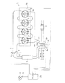
図1は、本実施例に係る内燃機関とその吸排気系の概略構成を示す図である。図1に示す内燃機関1は、4つの気筒2を有する水冷式の4気筒ガソリンエンジンである。
FIG. 1 is a diagram showing a schematic configuration of an internal combustion engine and its intake / exhaust system according to the present embodiment. An internal combustion engine 1 shown in FIG. 1 is a water-cooled four-cylinder gasoline engine having four
内燃機関1には、吸気通路3が接続されており、この吸気通路3は、エアクリーナボックス4に接続されている。そして、エアクリーナボックス4より下流の吸気通路3には、当該吸気通路3内を流通する吸気の質量に対応した電気信号を出力するエアフローメータ5が取り付けられている。
An
また、吸気通路3の途中には、過給機(ターボチャージャー)6のコンプレッサハウジング6aが設けられている。コンプレッサハウジング6aより下流の吸気通路3にはインタークーラ7が取り付けられている。なお、過給機6は、この過給機の回転軸6cが出力軸となるように電動機6dが内蔵されている電動機付過給機である。
A compressor housing 6 a of a supercharger (turbocharger) 6 is provided in the middle of the
インタークーラ7より下流の吸気通路3には、当該吸気通路3内を流通する吸気の流量を調整するスロットルバルブ8が設けられている。このスロットルバルブ8には、当該スロットルバルブ8を開閉駆動するアクチュエータ9が取り付けられている。
A
各気筒の燃焼室からの排気は、排気ポート、排気マニホールド10、過給機6のタービンハウジング6bなどから形成される排気通路を通る。そして、排気は、過給機6の下流の排気通路に設けられた排気浄化触媒11にて浄化された後、マフラー(図示省略)を通り、大気中に排出される。
Exhaust gas from the combustion chamber of each cylinder passes through an exhaust passage formed by an exhaust port, an
また、スロットルバルブ8の近傍には、当該スロットルバルブ8の開度に対応した電気信号を出力するスロットルポジションセンサ12が取り付けられており、当該内燃機関1が搭載された車両のアクセル13の近傍には、当該アクセル13の開度に対応した電気信号を出力するアクセルポジションセンサ14が取り付けられている。また、過給機6の回転軸6cの近傍には、当該回転軸6cの回転位相を検出する回転軸ポジションセンサ15が取り付けられており、内燃機関1のクランクシャフト(図示省略)の近傍には、当該クランクシャフトの回転位相を検出するクランクポジションセンサ16が取り付けられている。
In addition, a
以上述べたように構成された内燃機関1とその吸排気系には、電子制御ユニット(ECU:Electronic Control Unit)20が併設されている。このECU20は、CPU、ROM、RAM、バックアップRAM等からなる算術論理演算回路である。
The internal combustion engine 1 and the intake / exhaust system configured as described above are provided with an electronic control unit (ECU) 20. The
ECU20には、前述したエアフローメータ5、スロットルポジションセンサ12、アクセルポジションセンサ14、回転軸ポジションセンサ15、クランクポジションセンサ16、外気の圧力を検知する外気圧力センサ(図示省略)等の各種センサが電気配線を介して接続され、上記した各種センサの出力信号がECU20に入力されるようになっている。
Various types of sensors such as the air flow meter 5, the
そして、ECU20は、一定時間毎に実行すべき基本ルーチンにおいて、各種センサの出力信号を入力する。そして、例えば、ECU20は、一定時間毎に、回転軸ポジションセンサ15の信号の周波数から1分あたりの回転軸6cの回転数(以下、「ターボ回転速度」という。)と、クランクポジションセンサ16の信号の周波数から1分あたりのクランクシャフトの回転数(以下、「エンジン回転速度」という。)を算出する。
And ECU20 inputs the output signal of various sensors in the basic routine which should be performed for every fixed time. For example, the
一方、ECU20には、アクチュエータ9、電動機6d等が電気配線を介して接続され、ECU20が、アクチュエータ9、電動機6d等を制御することが可能になっている。
On the other hand, the
そして、電動機付過給機6を備える内燃機関用過給システムにおいては、ターボ回転速度が所望の目標ターボ回転速度となるように電動機6dを制御する。
And in the supercharging system for internal combustion engines provided with the
概略としては、ターボ回転速度の目標回転速度を算出し、回転軸ポジションセンサ15にて検出する現時点のターボ回転速度が、この目標ターボ回転速度より低い場合には電動アシストが必要であると判定し、ターボ回転速度が目標ターボ回転速度となるように電動機6dを制御する。
As an outline, the target rotational speed of the turbo rotational speed is calculated, and when the current turbo rotational speed detected by the rotary
以下に、目標ターボ回転速度の決定手法について説明する。 Hereinafter, a method for determining the target turbo rotation speed will be described.
(1)予め実験等の経験則に基づいてアクセル開度毎の最適な目標ターボ回転速度を算出し、目標ターボ回転速度とアクセル開度との相関関係を示すマップを作成しておく。このマップは、アクセル開度が0以上30%未満である場合には目標ターボ回転速度は零、アクセル開度が30%である場合の目標ターボ回転速度を3万(rpm)とし、アクセル開度が30%より大きくなるのに応じてアクセル開度に比例するように目標ターボ回転速度が3万(rpm)より大きくなるように作成されるものであることを例示することができる。そして、アクセルポジションセンサ14にて検出したアクセル開度を当該マップに代入することにより目標ターボ回転速度を算出して決定する。
(1) An optimal target turbo rotation speed for each accelerator opening is calculated in advance based on an empirical rule such as an experiment, and a map showing the correlation between the target turbo rotation speed and the accelerator opening is created. This map shows that when the accelerator opening is greater than or equal to 0 and less than 30%, the target turbo speed is zero, and when the accelerator opening is 30%, the target turbo speed is 30,000 (rpm). It can be exemplified that the target turbo rotation speed is made to be larger than 30,000 (rpm) so as to be proportional to the accelerator opening as the value becomes larger than 30%. Then, the target turbo rotation speed is calculated and determined by substituting the accelerator opening detected by the
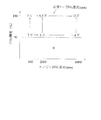
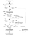
(2)予め実験等の経験則に基づいてアクセル開度及びエンジン回転速度に対する最適な目標ターボ回転速度を算出し、図2に示すような目標ターボ回転速度、アクセル開度及びエンジン回転速度の相関関係を示すマップを作成しておく。そして、アクセルポジションセンサ14にて検出したアクセル開度及びクランクポジションセンサ16にて検出したエンジン回転速度を当該マップに代入することにより目標ターボ回転速度を算出して決定する。
(2) Based on empirical rules such as experiments, the optimum target turbo speed for the accelerator opening and the engine speed is calculated in advance, and the correlation between the target turbo speed, the accelerator opening and the engine speed as shown in FIG. Create a map showing the relationship. Then, the target turbo rotation speed is calculated and determined by substituting the accelerator opening detected by the
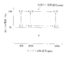
(3)予め実験等の経験則に基づいて実スロットル開度及びエンジン回転速度に対する最適な目標ターボ回転速度を算出し、図3に示すような目標ターボ回転速度、実スロットル開度及びエンジン回転速度の相関関係を示すマップを作成しておく。そして、スロット
ルポジションセンサ12にて検出した実スロットル開度及びクランクポジションセンサ16にて検出したエンジン回転速度を当該マップに代入することにより目標ターボ回転速度を算出して決定する。アクセル開度はドライバの意志であるが、変速や他の車両制御との関係でエンジンにとっての意志はスロットル開度で決まる。そのため、このようにスロットル開度を用いることによりエンジン状態に応じて適切に目標ターボ回転速度を決定することができる。
(3) Based on empirical rules such as experiments, an optimum target turbo speed for the actual throttle opening and engine speed is calculated in advance, and the target turbo speed, actual throttle opening and engine speed as shown in FIG. 3 are calculated. Create a map showing the correlation between the two. Then, the target turbo rotational speed is calculated and determined by substituting the actual throttle opening detected by the
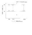
(4)予め実験等の経験則に基づいて目標スロットル開度及びエンジン回転速度に対する最適な目標ターボ回転速度を算出し、図4に示すような目標ターボ回転速度、目標スロットル開度及びエンジン回転速度の相関関係を示すマップを作成しておく。そして、アクセルポジションセンサ14にて検出したアクセル開度及びクランクポジションセンサ16にて検出したエンジン回転速度に基づいて算出される目標スロットル開度、及びクランクポジションセンサ16にて検出したエンジン回転速度を当該マップに代入することにより目標ターボ回転速度を算出して決定する。(3)においては実スロットル開度に基づいて目標ターボ回転速度を算出しているが、特に加速時などの過渡期においては、実スロットル開度がアクセル開度及びエンジン回転速度に基づいて算出される目標スロットル開度と等しくなるまでにはそれ相当の時間を要する。それゆえ、このように目標スロットル開度を用いることにより、より精度よくエンジン状態に応じて適切な目標ターボ回転速度に決定することができる。ただし、相当の時間を経過した後は、実スロットル開度と目標スロットル開度は同一であると考えられるので、単にスロットル開度センサにて検出した実スロットル開度に基づいて目標ターボ回転速度を算出する方がより簡易迅速に目標ターボ回転速度を算出することができる。
(4) An optimum target turbo speed for the target throttle opening and engine speed is calculated in advance based on empirical rules such as experiments, and the target turbo speed, target throttle opening and engine speed as shown in FIG. Create a map showing the correlation between the two. Then, the target throttle opening calculated based on the accelerator opening detected by the
なお、上述した目標ターボ回転速度を算出するために用いるマップにおいては、所定のアクセル開度、実スロットル開度あるいは目標スロットル開度以上は、エンジン回転速度毎に一定の目標ターボ回転速度とする方がより早い加速を得られる。しかしながら、図2〜4に示すように、アクセル開度、実スロットル開度あるいは目標スロットル開度の上昇に伴い段階的に目標ターボ回転速度を上昇させることで、ドライバビリティを向上させることができる。 In the map used for calculating the target turbo rotational speed described above, a predetermined target turbo rotational speed is set at a constant target turbo rotational speed for each engine rotational speed over a predetermined accelerator opening, actual throttle opening, or target throttle opening. Can get faster acceleration. However, as shown in FIGS. 2 to 4, drivability can be improved by increasing the target turbo rotation speed stepwise as the accelerator opening, the actual throttle opening, or the target throttle opening increases.
また、上述した目標ターボ回転速度を算出するために用いるマップを作成する際には、電動機にてターボ回転速度をアシストしない時(電動機非作動時)のエンジン定常状態での実ターボ回転速度に対して数%低い回転速度とすることが好適である。これにより、ターボラグ発生時のみの電動機作動が可能となる。その結果、過過給、過回転、無駄な電力消費を防止することができる。なお、エンジン定常状態でのターボ回転速度に対して低回転速度とする割合(前記数%)は、当該低められた回転速度までターボ回転速度が上昇したら、あとは排気エネルギー及び慣性力でエンジン定常状態でのターボ回転速度まで上昇するであろうと考えられる割合とするのが好適である。 Also, when creating the map used to calculate the target turbo speed described above, the actual turbo speed in the steady state of the engine when the motor does not assist the turbo speed (when the motor is not operating) is used. Therefore, it is preferable that the rotational speed be several percent lower. As a result, the electric motor can be operated only when the turbo lag is generated. As a result, it is possible to prevent supercharging, overspeeding, and wasteful power consumption. Note that the ratio of the low rotational speed to the turbo rotational speed in the steady state of the engine (several percent) is that when the turbo rotational speed is increased to the reduced rotational speed, the engine steady state is obtained by exhaust energy and inertial force. It is preferable that the ratio be considered to increase to the turbo rotational speed in the state.
以下、具体的に本実施例に係る電動アシスト制御の制御ルーチンについて図5に示すフローチャートに沿って説明する。この制御ルーチンは、予めECU10のROMに記憶されているルーチンであり、一定時間毎、あるいはクランクポジションセンサからのパルス信号の入力などをトリガとした割り込み処理としてECU10が実行するルーチンである。
Hereinafter, the control routine of the electric assist control according to the present embodiment will be specifically described along the flowchart shown in FIG. This control routine is a routine that is stored in advance in the ROM of the
本制御ルーチンでは、ECU10は、先ず、ステップ(以下、単に「S」という場合もある。)101において、アクセルポジションセンサ14、回転軸ポジションセンサ15、クランクポジションセンサ16、エアフローメータ4等からの入力信号を処理する。
In this control routine, the
その後、S102へ進み、電動アシスト実施条件が成立しているか否かを判別する。電
動アシスト実施条件が成立している場合としては、電動機の温度が高温ではない、エンジン回転速度が過給機を作動させる回転速度である、過給機がサージ領域に入っていないなどを例示することができる。そして、肯定判定された場合は、S103へ進む。一方、否定判定された場合は、S110へ進み、電動アシストを実施せずに本ルーチンの実行を終了する。
Thereafter, the process proceeds to S102, and it is determined whether or not the electric assist execution condition is satisfied. Examples of cases where the electric assist execution condition is satisfied include that the temperature of the electric motor is not high, the engine rotational speed is a rotational speed at which the turbocharger is operated, and the supercharger is not in the surge region. be able to. And when affirmation determination is carried out, it progresses to S103. On the other hand, if a negative determination is made, the process proceeds to S110, and the execution of this routine is terminated without performing the electric assist.
S103においては、目標ターボ回転速度を決定する。これは上述した手法(1)〜(4)のいずれかを用いて決定するものである。 In S103, a target turbo rotation speed is determined. This is determined using any one of the above-described methods (1) to (4).
その後、S104へ進み、S103にて決定した目標ターボ回転速度に対して、高地補正が必要であるか否かを判別する。高地の酸素濃度は低地の酸素濃度より低いため、現時点の位置が高地である場合には、通常よりもターボ回転速度を上昇させる必要がある。それゆえ、本ステップにて、高地補正が必要であるか否か、つまり外気圧力センサの検出値に基づいて把握する現在の位置が所定高度より高いか否かを判別する。 Thereafter, the process proceeds to S104, and it is determined whether or not high altitude correction is necessary for the target turbo rotation speed determined in S103. Since the oxygen concentration in the highland is lower than the oxygen concentration in the lowland, it is necessary to increase the turbo rotation speed more than usual when the current position is the highland. Therefore, in this step, it is determined whether or not the high altitude correction is necessary, that is, whether or not the current position grasped based on the detection value of the outside air pressure sensor is higher than the predetermined altitude.
そして、肯定判定、つまり現在の位置が所定高度より高く、高地補正が必要であると判定された場合には、S105へ進み、目標ターボ回転速度を補正する。これは、前記所定高度より高い場合には一律に所定回転速度だけ高くするようにしてもよいし、高度が大きくなるのに応じて回転速度を高めるようにしてもよい。 If the determination is affirmative, that is, if the current position is higher than the predetermined altitude and it is determined that high altitude correction is necessary, the process proceeds to S105, and the target turbo rotation speed is corrected. If the height is higher than the predetermined altitude, it may be uniformly increased by a predetermined rotation speed, or the rotation speed may be increased as the altitude increases.
一方、S104にて否定判定された場合は、S106へ進み、これまでのステップにて決定された目標ターボ回転速度にした場合に、気筒内のノック強度が大きいか否かを判別する。これは、各センサの出力値を基に燃焼室の温度を把握するなど、現時点の気筒の状態を把握し、当該状態でこれまでのステップにて決定された目標ターボ回転速度にした場合にノック強度が所定値より大きくなるか否かを判定するものである。 On the other hand, if a negative determination is made in S104, the process proceeds to S106, and it is determined whether or not the knock strength in the cylinder is large when the target turbo rotational speed determined in the previous steps is set. This is done by grasping the current cylinder state, such as grasping the temperature of the combustion chamber based on the output value of each sensor, and knocking when the target turbo rotation speed determined in the previous steps is reached in that state. It is determined whether or not the intensity is greater than a predetermined value.
そして、肯定判定された場合には、S107へ進み、目標ターボ回転速度を補正する。これは、ノック強度が所定値より大きい場合には一律に所定回転速度だけ低くするようにしてもよいし、ノック強度が大きくなるのに応じて回転速度を低めるようにしてもよい。所定値は予め実験等の経験則に基づいて決定されるものである。 If a positive determination is made, the process proceeds to S107, and the target turbo rotation speed is corrected. In this case, when the knock intensity is larger than a predetermined value, the rotation speed may be uniformly decreased by a predetermined rotation speed, or the rotation speed may be decreased as the knock intensity increases. The predetermined value is determined in advance based on empirical rules such as experiments.
一方、S106にて否定判定された場合は、S108へ進み、電動アシストが必要であるか否かを判別する。これは、現時点のターボ回転速度がこれまでのステップにて決定された目標ターボ回転速度より低い場合には電動アシストが必要であると判定するものである。そして、肯定判定された場合は、S109へ進み、ターボ回転速度がこれまでのステップにて決定された目標ターボ回転速度となるように電動アシストを実施する。一方、否定判定された場合は、S110へ進み、電動アシストを実施せずに本ルーチンの実行を終了する。 On the other hand, if a negative determination is made in S106, the process proceeds to S108 to determine whether or not electric assist is necessary. In this case, when the current turbo rotation speed is lower than the target turbo rotation speed determined in the steps so far, it is determined that the electric assist is necessary. If the determination is affirmative, the process proceeds to S109, and electric assist is performed so that the turbo rotation speed becomes the target turbo rotation speed determined in the steps so far. On the other hand, if a negative determination is made, the process proceeds to S110, and the execution of this routine is terminated without performing the electric assist.
なお、上述した(4)の手法で目標ターボ回転速度が決定される場合には、加速時に、先ず、アクセル開度、エンジン回転速度に基づいて目標スロットル開度が決定され、当該目標スロットル開度、エンジン回転速度及び図4に示すマップに基づいて目標ターボ回転速度が決定され、当該目標ターボ回転速度となるように電動機6にてアシストされる。そして、その後、実スロットル開度がアクセル開度及びエンジン回転速度に基づいて算出される目標スロットル開度と等しくなる相当の時間(所定期間)を経過した後は、実スロットル開度と目標スロットル開度は同一であると考えられるので、単にスロットルポジションセンサ12にて検出した実スロットル開度と図3に示すマップに基づいて目標ターボ回転速度を決定するのが好適である。かかる場合、前記相当の時間(所定期間)を、内燃機関の運転状態毎に、予め実験等の経験則に基づいて導き出しておき、電動アシスト実施開始後の経過時間が当該相当の時間(所定期間)を経過したか否かで切り替えることが好適
である。
When the target turbo rotation speed is determined by the method (4) described above, at the time of acceleration, first, the target throttle opening is determined based on the accelerator opening and the engine rotation speed. The target turbo rotation speed is determined based on the engine rotation speed and the map shown in FIG. 4 and is assisted by the
1 内燃機関
2 気筒
3 吸気通路
4 エアクリーナボックス
5 エアフローメータ
6 過給機
6c 回転軸
6d 電動機
7 インタークーラ
8 スロットルバルブ
9 アクチュエータ
10 排気マニホールド
11 排気浄化触媒
12 スロットルポジションセンサ
13 アクセル
14 アクセルポジションセンサ
15 回転軸ポジションセンサ
16 クランクポジションセンサ
20 ECU
DESCRIPTION OF SYMBOLS 1
Claims (3)
当該過給機の回転速度が目標回転速度となるように前記電動機によるアシスト力を制御する制御手段と、
を備える内燃機関用過給システムであって、
前記制御手段は、前記電動機によるアシスト開始後、所定期間は内燃機関の吸気通路に設けられたスロットルバルブの目標開度と内燃機関の回転速度とに基づいて、前記所定期間経過後は前記スロットルバルブの実開度と内燃機関の回転速度とに基づいて、前記過給機の目標回転速度を決定し、当該目標回転速度となるように前記アシスト力を制御することを特徴とする内燃機関用過給システム。 A supercharger with an electric motor that is supercharged using the exhaust energy of an internal combustion engine mounted on the vehicle and whose rotation shaft can be assisted by the electric motor;
Control means for controlling the assist force by the electric motor so that the rotational speed of the supercharger becomes the target rotational speed;
A supercharging system for an internal combustion engine comprising:
The control means is configured to start the assist by the electric motor based on a target opening degree of a throttle valve provided in an intake passage of the internal combustion engine and a rotational speed of the internal combustion engine for a predetermined period, and to perform the throttle valve after the predetermined period has elapsed. A target rotational speed of the supercharger is determined based on the actual opening of the engine and the rotational speed of the internal combustion engine, and the assist force is controlled so as to be the target rotational speed. Supply system.
Priority Applications (5)
| Application Number | Priority Date | Filing Date | Title |
|---|---|---|---|
| JP2005268422A JP4635793B2 (en) | 2005-09-15 | 2005-09-15 | Supercharging system for internal combustion engines |
| CN2006800340539A CN101268265B (en) | 2005-09-15 | 2006-07-26 | Supercharging system for internal combustion engine |
| EP06768406.8A EP1934442B1 (en) | 2005-09-15 | 2006-07-26 | Supercharging system for internal combustion engine |
| US11/991,789 US8006495B2 (en) | 2005-09-15 | 2006-07-26 | Supercharging system for internal combustion engine |
| PCT/JP2006/315251 WO2007032157A1 (en) | 2005-09-15 | 2006-07-26 | Supercharging system for internal combustion engine |
Applications Claiming Priority (1)
| Application Number | Priority Date | Filing Date | Title |
|---|---|---|---|
| JP2005268422A JP4635793B2 (en) | 2005-09-15 | 2005-09-15 | Supercharging system for internal combustion engines |
Publications (2)
| Publication Number | Publication Date |
|---|---|
| JP2007077909A JP2007077909A (en) | 2007-03-29 |
| JP4635793B2 true JP4635793B2 (en) | 2011-02-23 |
Family
ID=37102095
Family Applications (1)
| Application Number | Title | Priority Date | Filing Date |
|---|---|---|---|
| JP2005268422A Expired - Fee Related JP4635793B2 (en) | 2005-09-15 | 2005-09-15 | Supercharging system for internal combustion engines |
Country Status (5)
| Country | Link |
|---|---|
| US (1) | US8006495B2 (en) |
| EP (1) | EP1934442B1 (en) |
| JP (1) | JP4635793B2 (en) |
| CN (1) | CN101268265B (en) |
| WO (1) | WO2007032157A1 (en) |
Families Citing this family (17)
| Publication number | Priority date | Publication date | Assignee | Title |
|---|---|---|---|---|
| JP4127304B2 (en) * | 2006-09-06 | 2008-07-30 | トヨタ自動車株式会社 | Electric turbocharger |
| JP5331435B2 (en) * | 2008-10-07 | 2013-10-30 | ヤンマー株式会社 | engine |
| JP5152135B2 (en) * | 2008-12-19 | 2013-02-27 | 日産自動車株式会社 | Intake air amount control device for supercharged engine |
| EP2573356B1 (en) * | 2011-09-26 | 2018-05-30 | Kasi Technologies AB | Supercharging system and method for operation |
| US9856781B2 (en) | 2011-09-30 | 2018-01-02 | Eaton Corporation | Supercharger assembly with independent superchargers and motor/generator |
| WO2013049435A1 (en) | 2011-09-30 | 2013-04-04 | Eaton Corporation | Supercharger assembly for regeneration of throttling losses and method of control |
| WO2013049439A2 (en) | 2011-09-30 | 2013-04-04 | Eaton Corporation | Supercharger assembly with two rotor sets |
| EP3239488A3 (en) | 2012-03-29 | 2017-11-22 | Eaton Corporation | Electric energy generation using variable speed hybrid electric supercharger assembly |
| JP5518122B2 (en) * | 2012-04-02 | 2014-06-11 | 三菱電機株式会社 | Electric supercharger control device |
| EP2971640B1 (en) | 2013-03-12 | 2020-05-06 | Eaton Corporation | Adaptive state of charge regulation and control of variable speed hybrid electric supercharger assembly for efficient vehicle operation |
| JP5631465B1 (en) * | 2013-09-03 | 2014-11-26 | 三菱電機株式会社 | Electric supercharger control device and electric supercharger control method |
| JP2015137550A (en) * | 2014-01-20 | 2015-07-30 | いすゞ自動車株式会社 | Internal combustion engine turbocharging auxiliary system and internal combustion engine turbocharging auxiliary method |
| TWI553217B (en) * | 2015-11-20 | 2016-10-11 | Energy saving controller for fuel economy | |
| KR20180068186A (en) * | 2016-12-13 | 2018-06-21 | 현대자동차주식회사 | Method and system for controlling mhsg of mild hybrid electric vehicle |
| JP7021565B2 (en) * | 2018-03-05 | 2022-02-17 | トヨタ自動車株式会社 | Fuel cell system and its control method |
| CN111720204B (en) * | 2019-03-21 | 2021-08-17 | 上海汽车集团股份有限公司 | Engine control method and device |
| JP7226220B2 (en) * | 2019-09-20 | 2023-02-21 | トヨタ自動車株式会社 | Hybrid vehicle control device |
Citations (4)
| Publication number | Priority date | Publication date | Assignee | Title |
|---|---|---|---|---|
| JP2001280145A (en) * | 2000-03-30 | 2001-10-10 | Nissan Motor Co Ltd | Control device for engine with supercharger |
| JP2003239754A (en) * | 2002-02-18 | 2003-08-27 | Toyota Motor Corp | Supercharging pressure controller |
| JP2004162648A (en) * | 2002-11-14 | 2004-06-10 | Toyota Motor Corp | Protective device of generator for turbine |
| JP2004176688A (en) * | 2002-11-29 | 2004-06-24 | Nissan Motor Co Ltd | Controller for compression self-ignition engine and hybrid vehicle |
Family Cites Families (16)
| Publication number | Priority date | Publication date | Assignee | Title |
|---|---|---|---|---|
| DE3241024A1 (en) | 1982-11-06 | 1984-05-10 | Robert Bosch Gmbh, 7000 Stuttgart | METHOD AND DEVICE FOR DEMANDING CHARGER CONTROL IN INTERNAL COMBUSTION ENGINES |
| JP2782711B2 (en) | 1987-10-16 | 1998-08-06 | いすゞ自動車株式会社 | Control device for turbocharger with rotating electric machine |
| JP2893964B2 (en) * | 1990-12-28 | 1999-05-24 | いすゞ自動車株式会社 | Control device for turbocharger with rotating electric machine |
| JPH05231162A (en) | 1992-02-19 | 1993-09-07 | Isuzu Motors Ltd | Controller for turbocharger equipped with rotary electric machine |
| JPH08121183A (en) | 1994-10-27 | 1996-05-14 | Isuzu Motors Ltd | Control system for turbo charger with electrically driven power generator |
| DE19502150C1 (en) | 1995-01-25 | 1996-05-23 | Bosch Gmbh Robert | System for regulating supercharging of IC engine |
| US5906098A (en) * | 1996-07-16 | 1999-05-25 | Turbodyne Systems, Inc. | Motor-generator assisted turbocharging systems for use with internal combustion engines and control method therefor |
| DE19712850A1 (en) | 1997-03-27 | 1998-10-01 | Bosch Gmbh Robert | Device for controlling a diverter valve |
| US6705084B2 (en) | 2001-07-03 | 2004-03-16 | Honeywell International Inc. | Control system for electric assisted turbocharger |
| US6938420B2 (en) * | 2002-08-20 | 2005-09-06 | Nissan Motor Co., Ltd. | Supercharger for internal combustion engine |
| JP3952974B2 (en) * | 2003-03-17 | 2007-08-01 | トヨタ自動車株式会社 | Control device for internal combustion engine |
| JP3951951B2 (en) * | 2003-04-03 | 2007-08-01 | トヨタ自動車株式会社 | Control device for internal combustion engine |
| JP4124143B2 (en) * | 2004-03-04 | 2008-07-23 | トヨタ自動車株式会社 | Control device for supercharger with electric motor |
| JP4544106B2 (en) * | 2005-09-08 | 2010-09-15 | マツダ株式会社 | Engine supercharger |
| US7213585B2 (en) * | 2005-09-21 | 2007-05-08 | Ford Global Technologies, Llc | System and method for maintaining heated intake air |
| JP2008019835A (en) * | 2006-07-14 | 2008-01-31 | Mazda Motor Corp | Engine with supercharger |
-
2005
- 2005-09-15 JP JP2005268422A patent/JP4635793B2/en not_active Expired - Fee Related
-
2006
- 2006-07-26 EP EP06768406.8A patent/EP1934442B1/en not_active Expired - Fee Related
- 2006-07-26 WO PCT/JP2006/315251 patent/WO2007032157A1/en active Application Filing
- 2006-07-26 US US11/991,789 patent/US8006495B2/en not_active Expired - Fee Related
- 2006-07-26 CN CN2006800340539A patent/CN101268265B/en not_active Expired - Fee Related
Patent Citations (4)
| Publication number | Priority date | Publication date | Assignee | Title |
|---|---|---|---|---|
| JP2001280145A (en) * | 2000-03-30 | 2001-10-10 | Nissan Motor Co Ltd | Control device for engine with supercharger |
| JP2003239754A (en) * | 2002-02-18 | 2003-08-27 | Toyota Motor Corp | Supercharging pressure controller |
| JP2004162648A (en) * | 2002-11-14 | 2004-06-10 | Toyota Motor Corp | Protective device of generator for turbine |
| JP2004176688A (en) * | 2002-11-29 | 2004-06-24 | Nissan Motor Co Ltd | Controller for compression self-ignition engine and hybrid vehicle |
Also Published As
| Publication number | Publication date |
|---|---|
| CN101268265A (en) | 2008-09-17 |
| CN101268265B (en) | 2012-04-18 |
| WO2007032157A1 (en) | 2007-03-22 |
| JP2007077909A (en) | 2007-03-29 |
| EP1934442B1 (en) | 2013-05-29 |
| EP1934442A1 (en) | 2008-06-25 |
| US8006495B2 (en) | 2011-08-30 |
| US20080312803A1 (en) | 2008-12-18 |
Similar Documents
| Publication | Publication Date | Title |
|---|---|---|
| JP4635793B2 (en) | Supercharging system for internal combustion engines | |
| JP4650321B2 (en) | Control device | |
| US20060213194A1 (en) | Control apparatus for internal combustion engine and control method for the same | |
| JP4434174B2 (en) | Control device for an internal combustion engine with a supercharger | |
| JP2011185159A (en) | Abnormality diagnosing device of internal combustion engine with supercharger | |
| CN108463620A (en) | The control method and control device of exhaust gas by-pass valve | |
| JP2007009877A (en) | Abnormality diagnostic device for supercharging pressure control system | |
| JP2007291961A (en) | Control device of internal combustion engine with centrifugal compressor | |
| JP3544197B2 (en) | Electronic control unit for internal combustion engine | |
| JP6691498B2 (en) | Control device for internal combustion engine | |
| JP2007303294A (en) | Control device for internal combustion engine with supercharger | |
| JP4627432B2 (en) | Control device for an internal combustion engine with a supercharger | |
| JP2009002249A (en) | Device for estimating throttle upstream pressure of internal combustion engine | |
| JP2009007940A (en) | Cylinder-charged air quantity calculating apparatus for internal combustion engine | |
| JP2006144583A (en) | Control device for internal combustion engine | |
| JP4818344B2 (en) | Supercharging pressure control device for internal combustion engine | |
| JP2006029279A (en) | Control device for internal combustion engine | |
| JP4428150B2 (en) | Engine intake control device | |
| JP2001193573A (en) | Control device for internal combustion engine | |
| JP4858237B2 (en) | Control device for internal combustion engine | |
| JP4736485B2 (en) | Control device for internal combustion engine | |
| JP2008045406A (en) | Egr control device | |
| JP4241107B2 (en) | Control device for internal combustion engine | |
| JP2007009740A (en) | Control system for electric compressor | |
| JP2006017053A (en) | Fuel injection timing control device for internal combustion engine with supercharger |
Legal Events
| Date | Code | Title | Description |
|---|---|---|---|
| A621 | Written request for application examination |
Free format text: JAPANESE INTERMEDIATE CODE: A621 Effective date: 20080820 |
|
| A131 | Notification of reasons for refusal |
Free format text: JAPANESE INTERMEDIATE CODE: A131 Effective date: 20100831 |
|
| A521 | Written amendment |
Free format text: JAPANESE INTERMEDIATE CODE: A523 Effective date: 20100930 |
|
| TRDD | Decision of grant or rejection written | ||
| A01 | Written decision to grant a patent or to grant a registration (utility model) |
Free format text: JAPANESE INTERMEDIATE CODE: A01 Effective date: 20101026 |
|
| A01 | Written decision to grant a patent or to grant a registration (utility model) |
Free format text: JAPANESE INTERMEDIATE CODE: A01 |
|
| A61 | First payment of annual fees (during grant procedure) |
Free format text: JAPANESE INTERMEDIATE CODE: A61 Effective date: 20101108 |
|
| FPAY | Renewal fee payment (event date is renewal date of database) |
Free format text: PAYMENT UNTIL: 20131203 Year of fee payment: 3 |
|
| R151 | Written notification of patent or utility model registration |
Ref document number: 4635793 Country of ref document: JP Free format text: JAPANESE INTERMEDIATE CODE: R151 |
|
| FPAY | Renewal fee payment (event date is renewal date of database) |
Free format text: PAYMENT UNTIL: 20131203 Year of fee payment: 3 |
|
| LAPS | Cancellation because of no payment of annual fees |