JP4635282B2 - Autonomous inverter drive hydraulic unit - Google Patents
Autonomous inverter drive hydraulic unit Download PDFInfo
- Publication number
- JP4635282B2 JP4635282B2 JP27026499A JP27026499A JP4635282B2 JP 4635282 B2 JP4635282 B2 JP 4635282B2 JP 27026499 A JP27026499 A JP 27026499A JP 27026499 A JP27026499 A JP 27026499A JP 4635282 B2 JP4635282 B2 JP 4635282B2
- Authority
- JP
- Japan
- Prior art keywords
- pressure
- horsepower
- current
- flow rate
- maximum
- Prior art date
- Legal status (The legal status is an assumption and is not a legal conclusion. Google has not performed a legal analysis and makes no representation as to the accuracy of the status listed.)
- Expired - Lifetime
Links
Images

Classifications
-
- F—MECHANICAL ENGINEERING; LIGHTING; HEATING; WEAPONS; BLASTING
- F04—POSITIVE - DISPLACEMENT MACHINES FOR LIQUIDS; PUMPS FOR LIQUIDS OR ELASTIC FLUIDS
- F04C—ROTARY-PISTON, OR OSCILLATING-PISTON, POSITIVE-DISPLACEMENT MACHINES FOR LIQUIDS; ROTARY-PISTON, OR OSCILLATING-PISTON, POSITIVE-DISPLACEMENT PUMPS
- F04C14/00—Control of, monitoring of, or safety arrangements for, machines, pumps or pumping installations
-
- F—MECHANICAL ENGINEERING; LIGHTING; HEATING; WEAPONS; BLASTING
- F04—POSITIVE - DISPLACEMENT MACHINES FOR LIQUIDS; PUMPS FOR LIQUIDS OR ELASTIC FLUIDS
- F04D—NON-POSITIVE-DISPLACEMENT PUMPS
- F04D15/00—Control, e.g. regulation, of pumps, pumping installations or systems
- F04D15/0066—Control, e.g. regulation, of pumps, pumping installations or systems by changing the speed, e.g. of the driving engine
-
- F—MECHANICAL ENGINEERING; LIGHTING; HEATING; WEAPONS; BLASTING
- F04—POSITIVE - DISPLACEMENT MACHINES FOR LIQUIDS; PUMPS FOR LIQUIDS OR ELASTIC FLUIDS
- F04C—ROTARY-PISTON, OR OSCILLATING-PISTON, POSITIVE-DISPLACEMENT MACHINES FOR LIQUIDS; ROTARY-PISTON, OR OSCILLATING-PISTON, POSITIVE-DISPLACEMENT PUMPS
- F04C14/00—Control of, monitoring of, or safety arrangements for, machines, pumps or pumping installations
- F04C14/08—Control of, monitoring of, or safety arrangements for, machines, pumps or pumping installations characterised by varying the rotational speed
Landscapes
- Engineering & Computer Science (AREA)
- Mechanical Engineering (AREA)
- General Engineering & Computer Science (AREA)
- Control Of Positive-Displacement Pumps (AREA)
- Control Of Ac Motors In General (AREA)
Description
【0001】
【発明の属する技術分野】
この発明は、インバータで可変速モータを駆動して油圧ポンプを駆動する油圧ユニットに関する。
【0002】
【従来の技術】
従来、油圧ユニットとしては、油圧ポンプを駆動するサーボモータを、アクチュエータの動作に応じて、圧力制御時には、外部(主機側)から入力された圧力指令信号と、圧力センサが検出した油圧ポンプの吐出圧力を表す圧力信号との偏差を表す圧力制御信号で制御する一方、流量制御時には、外部から入力された流量指令信号と、回転センサが検出した流量に相当するサーボモータの回転速度信号との偏差を表す流量制御信号で制御するようにしたものがある(特開平5−196001号公報)。
【0003】
【発明が解決しようとする課題】
しかしながら、上記従来の油圧ユニットでは、外部から圧力指令信号と流量指令信号を入力するために、入力信号線が必要であるため、油圧ユニットの回りがこの入力信号線と電源線とで煩雑になるという問題があった。
【0004】
そこで、この発明の課題は、外部から入力信号線を接続する必要のない油圧ユニットを提供することにある。
【0005】
【課題を解決するための手段】
【0006】
【0007】
【0008】
【0009】
この発明の自律形インバータ駆動油圧ユニットは、
油圧ポンプと、
この油圧ポンプを駆動する可変速モータと、
この可変速モータを駆動するインバータと、
この油圧ポンプの負荷を検出する負荷センサと、
上記可変速モータまたは油圧ポンプの回転速度を検出する回転センサと、
上記油圧ポンプから吐出される流体の圧力および流量が、予め定められた目標圧力−流量特性線上の圧力および流量となるように、上記負荷センサと回転センサとの出力に基づいて、インバータに制御信号を出力するコントローラと、
上記コントローラに、電圧を降下させて直流電力を供給するコントローラ用電源回路と、
外部の交流電源から交流電力を受けて、上記インバータと上記コントローラ用電源回路とに直流電力を供給するコンバータと
を備え、
上記目標圧力−流量特性線は、最大流量直線と、最大馬力曲線または擬似最大馬力線と、最高圧力直線とからなり、
上記コントローラは、上記負荷センサと回転センサとの出力と上記目標圧力−流量特性線とに基づいて目標馬力を演算する目標馬力演算部と、上記負荷センサと回転センサとの出力に基づいて現在馬力を演算する現在馬力演算部と、上記目標馬力と現在馬力とを比較してインバータに制御信号を出力する比較部とを有し、
上記目標馬力演算部は、
上記最大流量直線と最大馬力曲線との交点と原点とを結ぶ第1直線と、最大馬力直線と最高圧力直線との交点と原点とを結ぶ第2直線とを記憶していて、縦軸と最大流量直線と第1直線とによって囲まれた第1領域と、第1直線,第2直線と最大馬力曲線とによって囲まれた第2領域と、第2直線と最高圧力直線と横軸とによって囲まれた第3領域とを定義しており、
上記目標馬力演算部は、
上記回転センサから入力された現在回転速度と、負荷センサから入力された現在圧力を表す信号とを受けて、この現在流量と現在圧力で表される現在の運転状態を表す点が、上記第1、第2及び第3領域のどの領域に属するかを演算によって識別できるようになっており、
上記目標馬力演算部は、
上記現在の運転状態を表す点が、第1領域に属するときには、最大設定流量×現在圧力=目標馬力とし、現在の運転状態を表す点が、第2領域に属するときには、最大設定馬力=目標馬力とし、また、現在の運転状態を表す点が、第3領域に属するときには、最高設定圧力×現在流量=目標馬力とし、このようにして求めた目標馬力を比較部に入力する
ことを特徴としている。
【0010】
上記構成によれば、上記コントローラの目標馬力演算部は、外部から指令信号を受けることなく、上記負荷センサと回転センサとの出力と上記目標圧力−流量特性線とに基づいて目標馬力を演算する。一方、上記現在馬力演算部は、負荷センサと回転センサとの出力に基づいて現在馬力を演算する。そして、上記比較部は、上記目標馬力と現在馬力とを比較してインバータに、現在馬力が目標馬力になるように、制御信号を出力する。このようにすることによって、簡単に、油圧ポンプから吐出される流体の流量および圧力が目標圧力−流量特性線上の値になる。
【0011】
請求項2の発明の自律形インバータ駆動油圧ユニットは、請求項1乃至3のいずれか1つに記載の自律形インバータ駆動油圧ユニットにおいて、上記負荷センサは上記可変速モータに流れる電流を検出する電流センサであることを特徴としている。
【0012】
上記構成によれば、上記負荷センサは可変速モータに流れる電流を検出する電流センサであるから、簡単に、油圧ポンプの吐出圧力を検出できる。
【0013】
請求項3の発明の自律形インバータ駆動油圧ユニットは、請求項1乃至3のいずれか1つに記載の自律形インバータ駆動油圧ユニットにおいて、上記負荷センサは油圧ポンプの吐出ラインの圧力を検出する圧力センサであることを特徴としている。
【0014】
上記構成によれば、上記負荷センサは油圧ポンプの吐出ラインの圧力を検出する圧力センサであるから、直接に、油圧ポンプの吐出ラインの圧力を正確に検出することができる。
【0015】
【発明の実施の形態】
以下、この発明を図示の実施の形態により詳細に説明する。
【0016】
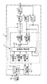
図1に示すように、この自律形インバータ駆動油圧ユニットJは、例えばギアポンプ、トロコイドポンプ、ベーンポンプ、ピストンポンプ等の固定容量形油圧ポンプ1を例えばスイッチトリラクタンスモータ、埋め込み磁石形モータ(IPM)等の可変速モータ2で駆動し、この可変速モータ2をインバータ3で駆動している。上記固定容量形油圧ポンプ1の吐出流量に相当する可変速モータ2の回転速度を回転センサ6で検出し、固定容量形油圧ポンプ1の吐出ラインの流体の圧力を負荷センサの一例としての圧力センサ6で検出している。上記インバータ3は、上記回転センサ5および圧力センサ6の出力を受けるコントローラ11からの制御信号によって、図示しないトランジスタのスイッチングを制御して、可変速モータ2を介して固定容量形油圧ポンプ1の回転数を制御している。このコントローラ11には、この自律形インバータ駆動油圧ユニットJの外部からの流量指令信号や圧力指令信号を入力していなくて、上記回転センサ5および圧力センサ6の出力に基づいて、後記するように、自律的に固定容量形油圧ポンプ1の流量および圧力を制御するようにしている。
【0017】
一方、交流電源(商用電源)15からの電源線を電源接続端子16に接続して、コンバータ17に交流電力を供給している。このコンバータ17から出力された平滑化された直流電力をインバータ3に供給すると共に、コントローラ用電源回路18に供給している。このコントローラ用電源回路18は、電圧を例えば5Vに降下させて、コントローラ11に低電圧の直流電力を供給している。上記コンバータ17とコントローラ用電源回路18とで電源装置を構成している。
【0018】
上記コントローラ1は、マイクロコンピュータからなり、設定手段の一例としての設定スイッチ21,22,23と、目標馬力演算部25と、現在馬力演算部26と、比較部27と、補償演算部28とを有する。上記設定スイッチ21,22,23は、夫々、最高設定圧力、最大設定流量、最大設定馬力を目標馬力演算部25の図示しない記憶部に予め入力する。上記目標馬力演算部25は、上記最高設定圧力、最大設定流量、最大設定馬力に基づいて、図2に示す目標圧力−流量特性線(に相当する情報)を作成して、記憶部に記憶する。この目標圧力−流量特性線は、図2に示すように、上記最大設定流量に対応する最大流量直線MVと、上記最大設定馬力に対応する双曲線からなる最大馬力曲線MHPと、上記最高設定圧力に対応する最高圧力直線MPとからなる。また、上記目標馬力演算部25は、最大流量直線MVと最大馬力曲線MHPとの交点Sと原点Oとを結ぶ直線SOと、最大馬力直線MHPと最高圧力直線MPとの交点Tと原点Oとを結ぶ直線TOとを記憶していて、縦軸(流量軸)と最大流量直線MVと直線SOとによって囲まれた領域aと、直線SO,TOと最大馬力曲線MHPとによって囲まれた領域bと、直線TOと最高圧力直線MPと横軸(圧力軸)とによって囲まれた領域cとを定義している。さらに、上記目標馬力演算部25は、上記回転センサ5から入力された回転速度、つまり、現在流量を表す信号と、圧力センサ6から入力された現在圧力を表す信号とを受けて、この現在流量と現在圧力で表される図2上の点、つまり、現在の運転状態を表す点(現在圧力,現在流量)が、上記領域a,b,cのどの領域に属するかを演算によって識別できるようになっている。この演算は、領域a,b,cの境界を定める直線あるいは曲線に対してその点(現在圧力,現在流量)がどちらにあるかを定める演算であって、上記直線あるいは曲線の式に上記点の座標(現在圧力,現在流量)を代入して正負を見るものである。
【0019】
さらにまた、上記目標馬力演算部25は、
図2において現在流量と現在圧力で表される現在の運転状態を表す点(現在圧力,現在流量)が、上記領域aに属するときには、
目標馬力=最大設定流量MV×現在圧力
とし、
また、図2において現在流量と現在圧力で表される現在の運転状態を表す点(現在圧力,現在流量)が、領域bに属するときには、
目標馬力=最大設定馬力
とし、
また、図2において現在流量と現在圧力で表される現在の運転状態を表す点(現在圧力,現在流量)が、領域cに属するときには、
目標馬力=最高設定圧力MP×現在流量
として、各領域a,b,cにおける目標馬力を演算して、比較部27に出力する。
【0020】
一方、上記現在馬力演算部26は、回転センサ5から受けた信号の表す可変速モータ2の回転速度、つまり、現在流量と、圧力センサ6から受けた信号の表す現在圧力との積である現在馬力を求めて、この現在馬力(=現在流量×現在圧力)を比較部27に出力する。この比較部27は、上記目標馬力と現在馬力との偏差を求めて、この偏差を表す制御信号を補償演算部28に出力する。この補償演算部28では、上記制御信号に、例えば、PI(比例積分)演算等の補償演算を行って、インバータ3に出力して、可変速モータ2の回転速度を制御して、現在馬力が目標馬力に一致するようにしている。すなわち、固定容量形油圧ポンプ1から出力される流体の圧力および流量を表す点(現在圧力,現在流量)が、図2に示す目標圧力−流量特性線の上に載るように、外部から指令圧力信号および指令流量信号を受けることなく、現在圧力および現在流量に基づいて、自律的な制御をするようになっている。
【0021】
上記構成の自律形インバータ駆動油圧ユニットにおいて、今、回転センサ5で検出した現在流量と、圧力センサ6で検出して現在圧力で表される現在の運転状態を表す点(現在圧力,現在流量)が、図2の領域aに属するときには、目標馬力演算部25は、最大設定流量MV×現在圧力=目標馬力とする。また、目標馬力演算部25は、現在の運転状態を表す点(現在圧力,現在流量)が、図2の領域bに属するときには、最大設定馬力=目標馬力とし、また、現在の運転状態を表す点(現在圧力,現在流量)が、図2の領域cに属するときには、最高設定圧力MP×現在流量=目標馬力とする。目標馬力演算部25は、このようにして求めた目標馬力を比較部27に入力する。この比較部27は、この目標馬力と現在馬力演算部26から受けた現在馬力との偏差を求めて、この偏差を表す制御信号を補償演算部28を介してインバータ3に入力して、可変速モータ2の回転数を制御して、現在馬力が目標馬力に一致するようにする。したがって、固定容量形油圧ポンプ1から出力される流体の圧力および流量を表す点(現在圧力,現在流量)が、図2に示す目標圧力−流量特性線の上に載る。
【0022】
このように、この自律形インバータ駆動油圧ユニットは、外部から指令圧力信号および指令流量信号を受けることなく、現在圧力および現在流量に基づいて、固定容量形油圧ポンプ1から出力される流体の圧力および流量を表す点(現在圧力,現在流量)が、図2に示す目標圧力−流量特性線の上に載るように、自律的な制御を行うのである。したがって、この自律形インバータ駆動油圧ユニットは、指令圧力信号および指令流量信号のための入力信号線を接続する必要がなくて、周りの配線が簡単になる。
【0023】
また、例えば、図2の領域cの保圧時においては、縦軸(流量軸)に略平行な最高圧力線MP上の点の小流量を固定容量形油圧ポンプ1が吐出するように、コントローラ11はインバータ3を介して可変速モータ2を低速で回転させて、少ない吐出流量の状態で、圧力を最高設定圧力MPに保持する。したがって、可変速モータ2および固定容量形油圧ポンプ1は必要以上の回転速度で回転することがなくなって、ロス馬力が少なくて省エネルギーを達成でき、かつ、騒音を低減できる。一方、図2の領域aで示す大きな流量を必要とするが圧力を必要としないときには、横軸(圧力軸)に略平行な最大流量直線MV上の点の小さな圧力に固定容量形油圧ポンプ1の吐出圧力がなるように、コントローラ11はインバータ3を介して可変速モータ2を回転させる。したがって、可変速モータ2および固定容量形油圧ポンプ1は必要以上の回転速度で回転することがなくなって、ロス馬力が少なくて省エネルギーを達成でき、かつ、騒音を低減できる。また、最大馬力を必要とするときには、最大馬力曲線MHP上の値になるように、コントローラ11はインバータ3を介して可変速モータ2を回転させる。
【0024】
上記実施の形態では、コントローラ11の目標馬力演算部25で、図2の領域a,b,cのどの領域に現在の運転状態を表す点(現在圧力,現在流量)があるかによって、上記目標圧力−流量特性線に基づいて目標馬力を演算して、比較部27からインバータ3に上記目標馬力と現在馬力との偏差を表す制御信号を出力して、現在馬力が目標馬力になるようにしているので、簡単に、固定容量形油圧ポンプ1から吐出される流体の流量および圧力を表す点(現在圧力,現在流量)が目標圧力−流量特性線上の値になるようにすることができる。
【0025】
さらに、この実施の形態では、電源装置をコンバータ17とコントローラ用電源回路18とによって構成しているので、電源接続端子16に交流電源(商用電源)15の電源線を接続するだけで、指令信号のための入力信号線を接続することなく、コントローラ11およびインバータ3に電力を供給できて、固定容量形油圧ポンプ1から吐出される流体の圧力および流量を、現在圧力および現在流量に基づいて、自律的に、図2の目標圧力−流量特性線上の値にすることができる。したがって、自律形インバータ駆動油圧ユニットJの回りに入力信号線がなくなって、回りがすっきりする。
【0026】
上記実施の形態では、目標圧力−流量特性線は、最大流量直線と最大馬力曲線と最高圧力直線とからなるが、最大馬力曲線に代えて斜線あるいは折れ線からなる擬似最大馬力線を用いてもよい。また、上記目標圧力−流量特性線は、動作上最も好ましい任意の曲線あるいは折れ線であってもよい。
【0027】
また、上記実施の形態では、現在圧力と現在流量が、目標圧力−流量特性線上の値にするために、領域a,b,cごとに目標馬力を求めているが、現在の運転状態を表す点(現在圧力,現在流量)と目標圧力−流量特性線との最短距離を求め、この最短距離となる目標圧力−流量特性線上の点の圧力と流量との積を目標馬力としてもよい。
【0028】
さらに、上記実施の形態では、負荷センサとして圧力センサ6を用いたが、この圧力センサ6に代えて、可変速モータ2の電流を検出する図示しない電流センサを用いてもよい。この電流センサは、可変容量型固定容量形油圧ポンプ1の吐出流体の圧力を、その圧力に相当する値を有する電流を介して簡単に検出できる。
【0029】
また、上記実施の形態では、設定スイッチ21,22,23を用いて、最高設定圧力、最大設定流量、最大設定馬力を設定するようにしたが、EEPROMあるいはフラッシュメモリを用いて、これらに最高設定圧力、最大設定流量、最大設定馬力を出荷後あるいは出荷前に書き込むようにしてもよい。
【0030】
また、上記実施の形態では、目標馬力と現在馬力との偏差を求めて、制御信号を得るようにしているが、目標圧力と現在圧力との偏差と、目標流量と現在流量との偏差とに基づいて、制御信号を得るようにしてもよい。
【0031】
また、上記実施の形態では、交流電源(商用電源)15を用いているから、電源装置にコンバータ17を設けていたが、直流電源(バッテリ)を用いる場合には、コンバータ17は不用である。
【0032】
また、上記実施の形態では、固定容量形油圧ポンプを用いたが、流量の上限値が変更できる可変容量形油圧ポンプを用いてもよい。
【0033】
【発明の効果】
【0034】
【0035】
この発明の自律形インバータ駆動油圧ユニットによれば、コントローラの目標馬力演算部が、外部から指令信号を受けることなく、負荷センサと回転センサとの出力と目標圧力−流量特性線とに基づいて目標馬力を演算する一方、現在馬力演算部が、負荷センサと回転センサとの出力に基づいて現在馬力を演算すると共に、比較部が、上記目標馬力と現在馬力とを比較して、現在馬力が目標馬力になるように、インバータに制御信号を出力するので、簡単に、油圧ポンプから吐出される流体の流量および圧力が目標圧力−流量特性線上の値になるようにすることができる。
【0036】
請求項2の発明の自律形インバータ駆動油圧ユニットによれば、負荷センサは可変速モータに流れる電流を検出する電流センサであるので、簡単に、油圧ポンプの吐出圧力を検出できる。
【0037】
請求項3の発明の自律形インバータ駆動油圧ユニットによれば、負荷センサは油圧ポンプの吐出ラインの圧力を検出する圧力センサであるので、直接に、油圧ポンプの吐出ラインの圧力を正確に検出することができる。
【図面の簡単な説明】
【図1】 この発明の実施の形態の自律形インバータ駆動油圧ユニットのブロック図である。
【図2】 目標圧力−流量特性線図である。
【符号の説明】
1 固定容量形油圧ポンプ
2 可変速モータ
3 インバータ
5 回転センサ
6 圧力センサ
11 コントローラ
17 コンバータ
18 コントローラ用電源回路
25 目標馬力演算部
26 現在馬力演算部
27 比較部[0001]
BACKGROUND OF THE INVENTION
The present invention relates to a hydraulic unit that drives a hydraulic pump by driving a variable speed motor with an inverter.
[0002]
[Prior art]
Conventionally, as a hydraulic unit, a servo motor that drives a hydraulic pump is controlled by a pressure command signal input from the outside (main machine side) according to the operation of the actuator, and the discharge of the hydraulic pump detected by the pressure sensor. While controlling with a pressure control signal that represents the deviation from the pressure signal that represents the pressure, during flow control, the deviation between the flow command signal input from the outside and the rotation speed signal of the servo motor corresponding to the flow detected by the rotation sensor Is controlled by a flow rate control signal representing the above (Japanese Patent Laid-Open No. 5-196001).
[0003]
[Problems to be solved by the invention]
However, since the conventional hydraulic unit requires an input signal line in order to input a pressure command signal and a flow rate command signal from the outside, the input signal line and the power supply line are complicated around the hydraulic unit. There was a problem.
[0004]
Therefore, an object of the present invention is to provide a hydraulic unit that does not require an input signal line to be connected from the outside.
[0005]
[Means for Solving the Problems]
[0006]
[0007]
[0008]
[0009]
The autonomous inverter drive hydraulic unit of this invention is
A hydraulic pump;
A variable speed motor that drives the hydraulic pump;
An inverter that drives the variable speed motor;
A load sensor for detecting the load of the hydraulic pump;
A rotation sensor for detecting the rotation speed of the variable speed motor or the hydraulic pump;
A control signal is sent to the inverter based on outputs of the load sensor and the rotation sensor so that the pressure and flow rate of the fluid discharged from the hydraulic pump become a pressure and flow rate on a predetermined target pressure-flow rate characteristic line. A controller that outputs
A controller power supply circuit for supplying DC power to the controller by dropping a voltage;
A converter that receives AC power from an external AC power source and supplies DC power to the inverter and the controller power supply circuit;
The target pressure-flow characteristic line consists of a maximum flow line, a maximum horsepower curve or pseudo maximum horsepower line, and a maximum pressure line.
The controller includes a target horsepower calculation unit that calculates a target horsepower based on outputs of the load sensor and the rotation sensor and the target pressure-flow rate characteristic line, and a current horsepower based on outputs of the load sensor and the rotation sensor. A current horsepower calculation unit that calculates the above, and a comparison unit that compares the target horsepower and the current horsepower and outputs a control signal to the inverter,
The target horsepower calculation unit is
The first straight line connecting the intersection of the maximum flow rate straight line and the maximum horsepower curve and the origin, and the second straight line connecting the intersection of the maximum horsepower straight line and the maximum pressure straight line and the origin are stored, and the vertical axis and the maximum Surrounded by the first region surrounded by the flow rate straight line and the first straight line, the second region surrounded by the first straight line, the second straight line and the maximum horsepower curve, the second straight line, the maximum pressure straight line and the horizontal axis. Defined third region,
The target horsepower calculation unit is
The first rotational speed inputted from the rotation sensor and the signal representing the current pressure inputted from the load sensor are received, and the point representing the current operation state represented by the current flow rate and the current pressure is the first. , Which region of the second and third regions can be identified by calculation,
The target horsepower calculation unit is
When the point representing the current operation state belongs to the first region, the maximum set flow rate × current pressure = target horsepower, and when the point representing the current operation state belongs to the second region, the maximum set horsepower = target horsepower. When the point representing the current operating state belongs to the third region, the maximum set pressure × current flow rate = target horsepower is set, and the target horsepower thus obtained is input to the comparison unit. .
[0010]
According to the above configuration, the target horsepower calculation unit of the controller calculates the target horsepower based on the output of the load sensor and the rotation sensor and the target pressure-flow rate characteristic line without receiving a command signal from the outside. . On the other hand, the current horsepower calculation unit calculates the current horsepower based on the outputs of the load sensor and the rotation sensor. The comparison unit compares the target horsepower with the current horsepower and outputs a control signal to the inverter so that the current horsepower becomes the target horsepower. By doing so, the flow rate and pressure of the fluid discharged from the hydraulic pump can be simply set to values on the target pressure-flow rate characteristic line.
[0011]
The autonomous inverter-driven hydraulic unit according to claim 2 is the autonomous inverter-driven hydraulic unit according to any one of claims 1 to 3, wherein the load sensor detects a current flowing through the variable speed motor. It is a sensor.
[0012]
According to the above configuration, since the load sensor is a current sensor that detects a current flowing through the variable speed motor, the discharge pressure of the hydraulic pump can be easily detected.
[0013]
The autonomous inverter-driven hydraulic unit according to a third aspect of the invention is the autonomous inverter-driven hydraulic unit according to any one of the first to third aspects, wherein the load sensor detects a pressure in a discharge line of a hydraulic pump. It is a sensor.
[0014]
According to the above configuration, since the load sensor is a pressure sensor that detects the pressure of the discharge line of the hydraulic pump, it can directly detect the pressure of the discharge line of the hydraulic pump.
[0015]
DETAILED DESCRIPTION OF THE INVENTION
Hereinafter, the present invention will be described in detail with reference to the illustrated embodiments.
[0016]
As shown in FIG. 1, this autonomous inverter-driven hydraulic unit J includes a fixed displacement hydraulic pump 1 such as a gear pump, a trochoid pump, a vane pump, and a piston pump, for example, a switched reluctance motor, an embedded magnet motor (IPM), or the like. This variable speed motor 2 is driven by an inverter 3. The rotational speed of the variable speed motor 2 corresponding to the discharge flow rate of the fixed displacement hydraulic pump 1 is detected by the rotation sensor 6, and the pressure of the fluid in the discharge line of the fixed displacement hydraulic pump 1 is a pressure sensor as an example of a load sensor. 6 is detected. The inverter 3 controls the switching of a transistor (not shown) by a control signal from the controller 11 that receives the outputs of the
[0017]
On the other hand, a power line from an AC power source (commercial power source) 15 is connected to the
[0018]
The controller 1 is composed of a microcomputer, and includes setting switches 21, 22, and 23 as an example of setting means, a target
[0019]
Furthermore, the target
When the point (current pressure, current flow rate) representing the current operation state represented by the current flow rate and the current pressure in FIG. 2 belongs to the region a,
Target horsepower = maximum set flow rate MV x current pressure,
In addition, when the point (current pressure, current flow rate) representing the current operation state represented by the current flow rate and the current pressure in FIG.
Target horsepower = maximum set horsepower,
In addition, when the point (current pressure, current flow rate) representing the current operation state represented by the current flow rate and the current pressure in FIG. 2 belongs to the region c,
Target horsepower in each region a, b, c is calculated as target horsepower = maximum set pressure MP × current flow rate, and is output to the
[0020]
On the other hand, the current
[0021]
In the autonomous inverter-driven hydraulic unit configured as described above, the current flow rate detected by the
[0022]
As described above, the autonomous inverter-driven hydraulic unit receives the pressure of the fluid output from the fixed displacement hydraulic pump 1 based on the current pressure and the current flow rate without receiving the command pressure signal and the command flow rate signal from the outside. The autonomous control is performed so that the point (current pressure, current flow rate) representing the flow rate is placed on the target pressure-flow rate characteristic line shown in FIG. Therefore, the autonomous inverter-driven hydraulic unit does not need to connect input signal lines for the command pressure signal and the command flow rate signal, and the surrounding wiring is simplified.
[0023]
Further, for example, at the time of holding pressure in the region c of FIG. 2, the controller is configured so that the fixed displacement hydraulic pump 1 discharges a small flow rate at a point on the maximum pressure line MP substantially parallel to the vertical axis (flow rate axis). 11 rotates the variable speed motor 2 at a low speed via the inverter 3 to maintain the pressure at the maximum set pressure MP with a small discharge flow rate. Therefore, the variable speed motor 2 and the fixed displacement hydraulic pump 1 can be prevented from rotating at an unnecessarily high rotational speed, energy loss can be achieved with less loss horsepower, and noise can be reduced. On the other hand, when a large flow rate shown in the region a of FIG. 2 is required but no pressure is required, the fixed displacement hydraulic pump 1 is adjusted to a small pressure at a point on the maximum flow straight line MV substantially parallel to the horizontal axis (pressure axis). The controller 11 rotates the variable speed motor 2 via the inverter 3 so that the discharge pressure becomes the same. Therefore, the variable speed motor 2 and the fixed displacement hydraulic pump 1 can be prevented from rotating at an unnecessarily high rotational speed, energy loss can be achieved with less loss horsepower, and noise can be reduced. When the maximum horsepower is required, the controller 11 rotates the variable speed motor 2 via the inverter 3 so that the value on the maximum horsepower curve MHP is obtained.
[0024]
In the above embodiment, the target
[0025]
Further, in this embodiment, since the power supply device is constituted by the
[0026]
In the above embodiment, the target pressure-flow rate characteristic line is composed of a maximum flow rate line, a maximum horsepower curve, and a maximum pressure line, but a pseudo maximum horsepower line composed of a diagonal line or a broken line may be used instead of the maximum horsepower curve. . The target pressure-flow rate characteristic line may be an arbitrary curve or a broken line that is most preferable in operation.
[0027]
In the above embodiment, the target horsepower is obtained for each of the regions a, b, and c so that the current pressure and the current flow rate are values on the target pressure-flow rate characteristic line. The shortest distance between the point (current pressure, current flow rate) and the target pressure-flow rate characteristic line may be obtained, and the product of the pressure and the flow rate at the point on the target pressure-flow rate characteristic line that will be the shortest distance may be used as the target horsepower.
[0028]
Furthermore, in the above embodiment, the pressure sensor 6 is used as the load sensor. However, a current sensor (not shown) that detects the current of the variable speed motor 2 may be used instead of the pressure sensor 6. This current sensor can easily detect the pressure of the fluid discharged from the variable displacement fixed displacement hydraulic pump 1 via a current having a value corresponding to the pressure.
[0029]
In the above embodiment, the setting switches 21, 22, and 23 are used to set the maximum setting pressure, the maximum setting flow rate, and the maximum setting horsepower, but these are set to the maximum setting using an EEPROM or flash memory. The pressure, the maximum set flow rate, and the maximum set horsepower may be written after shipment or before shipment.
[0030]
In the above embodiment, the control signal is obtained by obtaining the deviation between the target horsepower and the current horsepower. However, the deviation between the target pressure and the current pressure and the deviation between the target flow rate and the current flow rate are obtained. Based on this, a control signal may be obtained.
[0031]
Moreover, in the said embodiment, since AC power supply (commercial power supply) 15 was used, the
[0032]
In the above embodiment, the fixed displacement hydraulic pump is used. However, a variable displacement hydraulic pump capable of changing the upper limit value of the flow rate may be used.
[0033]
【The invention's effect】
[0034]
[0035]
According to the autonomous inverter-driven hydraulic unit of the present invention, the target horsepower calculation unit of the controller receives the command signal from the outside and receives the target based on the output of the load sensor and the rotation sensor and the target pressure-flow rate characteristic line. While calculating the horsepower, the current horsepower calculation unit calculates the current horsepower based on the outputs of the load sensor and the rotation sensor, and the comparison unit compares the target horsepower with the current horsepower to determine the current horsepower. Since the control signal is output to the inverter so as to achieve horsepower, the flow rate and pressure of the fluid discharged from the hydraulic pump can be easily set to values on the target pressure-flow rate characteristic line.
[0036]
According to the autonomous inverter-driven hydraulic unit of the second aspect of the invention, since the load sensor is a current sensor that detects the current flowing through the variable speed motor, the discharge pressure of the hydraulic pump can be easily detected.
[0037]
According to the autonomous inverter-driven hydraulic unit of the invention of claim 3 , since the load sensor is a pressure sensor that detects the pressure of the discharge line of the hydraulic pump, it directly detects the pressure of the discharge line of the hydraulic pump directly. be able to.
[Brief description of the drawings]
FIG. 1 is a block diagram of an autonomous inverter-driven hydraulic unit according to an embodiment of the present invention.
FIG. 2 is a target pressure-flow rate characteristic diagram.
[Explanation of symbols]
DESCRIPTION OF SYMBOLS 1 Fixed displacement hydraulic pump 2 Variable speed motor 3
Claims (3)
この油圧ポンプ(1)を駆動する可変速モータ(2)と、
この可変速モータ(2)を駆動するインバータ(3)と、
この油圧ポンプ(1)の負荷を検出する負荷センサ(6)と、
上記可変速モータ(2)または油圧ポンプ(1)の回転速度を検出する回転センサ(5)と、
上記油圧ポンプ(1)から吐出される流体の圧力および流量が、予め定められた目標圧力−流量特性線上の圧力および流量となるように、上記負荷センサ(6)と回転センサ(5)との出力に基づいて、インバータ(3)に制御信号を出力するコントローラ(11)と、
上記コントローラ(11)に、電圧を降下させて直流電力を供給するコントローラ用電源回路(18)と、
外部の交流電源(15)から交流電力を受けて、上記インバータ(3)と上記コントローラ用電源回路(18)とに直流電力を供給するコンバータ(17)と
を備え、
上記目標圧力−流量特性線は、最大流量直線(MV)と、最大馬力曲線(MHP)または擬似最大馬力線と、最高圧力直線(MP)とからなり、
上記コントローラ(11)は、上記負荷センサ(6)と回転センサ(5)との出力と上記目標圧力−流量特性線とに基づいて目標馬力を演算する目標馬力演算部(25)と、上記負荷センサ(6)と回転センサ(5)との出力に基づいて現在馬力を演算する現在馬力演算部(26)と、上記目標馬力と現在馬力とを比較してインバータ(3)に制御信号を出力する比較部(27)とを有し、
上記目標馬力演算部(25)は、
上記最大流量直線(MV)と最大馬力曲線(MH)との交点(S)と原点(O)とを結ぶ第1直線(SO)と、最大馬力直線(MHP)と最高圧力直線(MP)との交点(T)と原点(O)とを結ぶ第2直線(TO)とを記憶していて、縦軸と最大流量直線(MV)と第1直線(SO)とによって囲まれた第1領域(a)と、第1直線(SO),第2直線(TO)と最大馬力曲線(MHP)とによって囲まれた第2領域(b)と、第2直線(TO)と最高圧力直線(MP)と横軸とによって囲まれた第3領域(c)とを定義しており、
上記目標馬力演算部(25)は、
上記回転センサ(5)から入力された現在回転速度と、負荷センサ(6)から入力された現在圧力を表す信号とを受けて、この現在流量と現在圧力で表される現在の運転状態を表す点が、上記第1、第2及び第3領域(a,b,c)のどの領域に属するかを演算によって識別できるようになっており、
上記目標馬力演算部(25)は、
上記現在の運転状態を表す点が、第1領域(a)に属するときには、最大設定流量(MV)×現在圧力=目標馬力とし、現在の運転状態を表す点が、第2領域(b)に属するときには、最大設定馬力=目標馬力とし、また、現在の運転状態を表す点が、第3領域(c)に属するときには、最高設定圧力(MP)×現在流量=目標馬力とし、このようにして求めた目標馬力を比較部に入力する
ことを特徴とする自律形インバータ駆動油圧ユニット。A hydraulic pump (1);
A variable speed motor (2) for driving the hydraulic pump (1);
An inverter (3) for driving the variable speed motor (2);
A load sensor (6) for detecting the load of the hydraulic pump (1);
A rotation sensor (5) for detecting the rotation speed of the variable speed motor (2) or the hydraulic pump (1);
The load sensor (6) and the rotation sensor (5) are arranged so that the pressure and flow rate of the fluid discharged from the hydraulic pump (1) are the pressure and flow rate on a predetermined target pressure-flow rate characteristic line. A controller (11) for outputting a control signal to the inverter (3) based on the output;
A controller power supply circuit (18) for supplying DC power to the controller (11) by dropping a voltage;
A converter (17) that receives AC power from an external AC power supply (15) and supplies DC power to the inverter (3) and the controller power supply circuit (18);
The target pressure-flow rate characteristic line is composed of a maximum flow rate line (MV), a maximum horsepower curve (MHP) or a pseudo maximum horsepower line, and a maximum pressure line (MP).
The controller (11) includes a target horsepower calculation unit (25) for calculating a target horsepower based on outputs of the load sensor (6) and the rotation sensor (5) and the target pressure-flow rate characteristic line, and the load A current horsepower calculation unit (26) that calculates the current horsepower based on outputs of the sensor (6) and the rotation sensor (5), and compares the target horsepower with the current horsepower and outputs a control signal to the inverter (3). A comparison unit (27)
The target horsepower calculation unit (25)
A first straight line (SO) connecting the intersection (S) of the maximum flow rate straight line (MV) and the maximum horsepower curve (MH) and the origin (O), a maximum horsepower straight line (MHP), and a maximum pressure straight line (MP); A first straight line (TO) connecting the intersection (T) and the origin (O), and a first region surrounded by the vertical axis, the maximum flow straight line (MV), and the first straight line (SO). (A), a second region (b) surrounded by a first straight line (SO), a second straight line (TO) and a maximum horsepower curve (MHP), a second straight line (TO) and a maximum pressure straight line (MP ) And the third region (c) surrounded by the horizontal axis,
The target horsepower calculation unit (25)
Receiving the current rotation speed input from the rotation sensor (5) and the signal indicating the current pressure input from the load sensor (6), the current operation state represented by the current flow rate and the current pressure is expressed. It is possible to identify by calculation whether the point belongs to one of the first, second and third regions (a, b, c),
The target horsepower calculation unit (25)
When the point representing the current operating state belongs to the first region (a), the maximum set flow rate (MV) × current pressure = target horsepower, and the point representing the current operating state is in the second region (b). When belonging, the maximum set horsepower = target horsepower is set, and when the point representing the current operating state belongs to the third region (c), the maximum set pressure (MP) × current flow rate = target horsepower is set. An autonomous inverter-driven hydraulic unit, wherein the obtained target horsepower is input to a comparison unit.
Priority Applications (7)
| Application Number | Priority Date | Filing Date | Title |
|---|---|---|---|
| JP27026499A JP4635282B2 (en) | 1999-09-24 | 1999-09-24 | Autonomous inverter drive hydraulic unit |
| EP00961010A EP1134421B1 (en) | 1999-09-24 | 2000-09-14 | Autonomous inverter driving hydraulic unit |
| CNB008027943A CN1201087C (en) | 1999-09-24 | 2000-09-14 | Autonomous inverter driving hydraulic unit |
| PCT/JP2000/006299 WO2001021959A1 (en) | 1999-09-24 | 2000-09-14 | Autonomous inverter driving hydraulic unit |
| US09/856,664 US6537032B1 (en) | 1999-09-24 | 2000-09-14 | Load dependent variable speed hydraulic unit |
| DE60041866T DE60041866D1 (en) | 1999-09-24 | 2000-09-14 | AUTONOMOUS HYDRAULIC DRIVE UNIT FOR AN INVERTER |
| KR10-2001-7006519A KR100399288B1 (en) | 1999-09-24 | 2000-09-14 | Autonomous inverter-driven hydraulic unit |
Applications Claiming Priority (1)
| Application Number | Priority Date | Filing Date | Title |
|---|---|---|---|
| JP27026499A JP4635282B2 (en) | 1999-09-24 | 1999-09-24 | Autonomous inverter drive hydraulic unit |
Publications (2)
| Publication Number | Publication Date |
|---|---|
| JP2001090671A JP2001090671A (en) | 2001-04-03 |
| JP4635282B2 true JP4635282B2 (en) | 2011-02-23 |
Family
ID=17483838
Family Applications (1)
| Application Number | Title | Priority Date | Filing Date |
|---|---|---|---|
| JP27026499A Expired - Lifetime JP4635282B2 (en) | 1999-09-24 | 1999-09-24 | Autonomous inverter drive hydraulic unit |
Country Status (7)
| Country | Link |
|---|---|
| US (1) | US6537032B1 (en) |
| EP (1) | EP1134421B1 (en) |
| JP (1) | JP4635282B2 (en) |
| KR (1) | KR100399288B1 (en) |
| CN (1) | CN1201087C (en) |
| DE (1) | DE60041866D1 (en) |
| WO (1) | WO2001021959A1 (en) |
Families Citing this family (33)
| Publication number | Priority date | Publication date | Assignee | Title |
|---|---|---|---|---|
| US8337166B2 (en) * | 2001-11-26 | 2012-12-25 | Shurflo, Llc | Pump and pump control circuit apparatus and method |
| JP4438281B2 (en) * | 2002-11-15 | 2010-03-24 | ダイキン工業株式会社 | Pump driving method and apparatus |
| US8540493B2 (en) * | 2003-12-08 | 2013-09-24 | Sta-Rite Industries, Llc | Pump control system and method |
| JP4272112B2 (en) * | 2004-05-26 | 2009-06-03 | 株式会社日立製作所 | Motor-integrated internal gear pump and electronic equipment |
| US8019479B2 (en) | 2004-08-26 | 2011-09-13 | Pentair Water Pool And Spa, Inc. | Control algorithm of variable speed pumping system |
| US7845913B2 (en) * | 2004-08-26 | 2010-12-07 | Pentair Water Pool And Spa, Inc. | Flow control |
| US7874808B2 (en) | 2004-08-26 | 2011-01-25 | Pentair Water Pool And Spa, Inc. | Variable speed pumping system and method |
| US8469675B2 (en) | 2004-08-26 | 2013-06-25 | Pentair Water Pool And Spa, Inc. | Priming protection |
| US7686589B2 (en) | 2004-08-26 | 2010-03-30 | Pentair Water Pool And Spa, Inc. | Pumping system with power optimization |
| US8480373B2 (en) | 2004-08-26 | 2013-07-09 | Pentair Water Pool And Spa, Inc. | Filter loading |
| US7854597B2 (en) | 2004-08-26 | 2010-12-21 | Pentair Water Pool And Spa, Inc. | Pumping system with two way communication |
| US8602745B2 (en) | 2004-08-26 | 2013-12-10 | Pentair Water Pool And Spa, Inc. | Anti-entrapment and anti-dead head function |
| JP4356623B2 (en) | 2005-02-03 | 2009-11-04 | ダイキン工業株式会社 | Fluid pressure unit and method for controlling fluid pressure unit |
| DE102006041317A1 (en) * | 2006-09-01 | 2008-03-20 | Oase Gmbh | Water pump for suspended waters containing water |
| DE502007004387D1 (en) * | 2007-03-23 | 2010-08-26 | Grundfos Management As | Method for detecting faults in pump sets |
| JP4424370B2 (en) * | 2007-05-02 | 2010-03-03 | ダイキン工業株式会社 | Hydraulic unit and construction machine having the same |
| WO2008143859A1 (en) * | 2007-05-14 | 2008-11-27 | Environment One Corporation | Wattmeter circuit for operating a grinder pump assembly to inhibit operating under run dry or blocked conditions |
| KR100859075B1 (en) * | 2007-06-13 | 2008-09-17 | 주식회사 대우일렉트로닉스 | Apparatus and method for controlling a compressor |
| JP4548488B2 (en) * | 2008-01-22 | 2010-09-22 | ダイキン工業株式会社 | Merge control system |
| EP2107237A1 (en) * | 2008-03-31 | 2009-10-07 | AMSC Windtec GmbH | Wind energy converter comprising a superposition gear |
| ES2773888T3 (en) | 2008-10-06 | 2020-07-15 | Danfoss Low Power Drives | Method of operating a vacuum release safety system |
| US9556874B2 (en) | 2009-06-09 | 2017-01-31 | Pentair Flow Technologies, Llc | Method of controlling a pump and motor |
| US8564233B2 (en) | 2009-06-09 | 2013-10-22 | Sta-Rite Industries, Llc | Safety system and method for pump and motor |
| US9243413B2 (en) | 2010-12-08 | 2016-01-26 | Pentair Water Pool And Spa, Inc. | Discharge vacuum relief valve for safety vacuum release system |
| EP2774009B1 (en) | 2011-11-01 | 2017-08-16 | Pentair Water Pool and Spa, Inc. | Flow locking system and method |
| JP2013231389A (en) * | 2012-04-27 | 2013-11-14 | Daikin Industries Ltd | Hydraulic device and industrial machine |
| US9022165B2 (en) * | 2012-07-03 | 2015-05-05 | GM Global Technology Operations LLC | Vehicle lubrication flow control |
| US9885360B2 (en) | 2012-10-25 | 2018-02-06 | Pentair Flow Technologies, Llc | Battery backup sump pump systems and methods |
| DE102015207682B4 (en) * | 2015-04-27 | 2018-10-11 | Continental Automotive Gmbh | Method for controlling a fuel delivery pump |
| EP3469444B1 (en) * | 2016-06-14 | 2024-02-14 | S. A. Armstrong Limited | Self-regulating open circuit pump unit |
| DE102017117595A1 (en) * | 2017-08-03 | 2019-02-07 | Voith Patent Gmbh | METHOD FOR CONTROLLING THE OUTPUT PRESSURE OF A HYDRAULIC DRIVE SYSTEM, USE OF THE METHOD AND HYDRAULIC DRIVE SYSTEM |
| KR102569439B1 (en) | 2017-09-25 | 2023-08-22 | 존슨 컨트롤스 테크놀러지 컴퍼니 | Variable speed drive input current control |
| CN109768756A (en) * | 2019-03-21 | 2019-05-17 | 珠海格力电器股份有限公司 | A kind of motor control method, device, motor and computer readable storage medium |
Citations (9)
| Publication number | Priority date | Publication date | Assignee | Title |
|---|---|---|---|---|
| JPS4858282A (en) * | 1971-11-24 | 1973-08-15 | ||
| JPS6072997U (en) * | 1983-10-26 | 1985-05-22 | 株式会社日立製作所 | pressure control device |
| JPS60184994A (en) * | 1984-03-02 | 1985-09-20 | Hitachi Ltd | Pump feed water supply system |
| JPH02213640A (en) * | 1989-02-13 | 1990-08-24 | Matsushita Refrig Co Ltd | Air conditioner |
| JPH05196001A (en) * | 1992-01-17 | 1993-08-06 | Tokimec Inc | Flow rate and pressure control device for servomotor drive hydraulic pump |
| JPH07337072A (en) * | 1994-06-07 | 1995-12-22 | Nippondenso Co Ltd | Protector for sealed compressor |
| JPH10131866A (en) * | 1996-10-31 | 1998-05-19 | Ebara Corp | Control device integrated rotating machine |
| JPH11159465A (en) * | 1997-11-27 | 1999-06-15 | Hitachi Constr Mach Co Ltd | High and low speed switching circuit for earth drill |
| JPH11210635A (en) * | 1998-01-29 | 1999-08-03 | Ebara Corp | Rotary machine integratedly formed with control device |
Family Cites Families (9)
| Publication number | Priority date | Publication date | Assignee | Title |
|---|---|---|---|---|
| DE2355966A1 (en) * | 1973-11-09 | 1975-05-22 | Medac Klinische Spezialpraep | PUMP ARRANGEMENT, ESPECIALLY FOR BLOOD PUMPS |
| US4225290A (en) * | 1979-02-22 | 1980-09-30 | Instrumentation Specialties Company | Pumping system |
| US4474104A (en) * | 1983-04-11 | 1984-10-02 | Double A Products Co. | Control system for variable displacement pumps and motors |
| US4595495A (en) * | 1985-02-22 | 1986-06-17 | Eldex Laboratories, Inc. | Programmable solvent delivery system and process |
| US4617637A (en) * | 1985-07-09 | 1986-10-14 | Lifecare Services, Inc. | Servo control system for a reciprocating piston respirator |
| US4850805A (en) * | 1987-03-13 | 1989-07-25 | Critikon, Inc. | Pump control system |
| US4795314A (en) * | 1987-08-24 | 1989-01-03 | Cobe Laboratories, Inc. | Condition responsive pump control utilizing integrated, commanded, and sensed flowrate signals |
| JPH0668189B2 (en) | 1988-06-29 | 1994-08-31 | 小松ウォール工業株式会社 | Suspended ceiling system |
| US5240380A (en) * | 1991-05-21 | 1993-08-31 | Sundstrand Corporation | Variable speed control for centrifugal pumps |
-
1999
- 1999-09-24 JP JP27026499A patent/JP4635282B2/en not_active Expired - Lifetime
-
2000
- 2000-09-14 KR KR10-2001-7006519A patent/KR100399288B1/en active IP Right Grant
- 2000-09-14 US US09/856,664 patent/US6537032B1/en not_active Expired - Lifetime
- 2000-09-14 DE DE60041866T patent/DE60041866D1/en not_active Expired - Lifetime
- 2000-09-14 EP EP00961010A patent/EP1134421B1/en not_active Expired - Lifetime
- 2000-09-14 WO PCT/JP2000/006299 patent/WO2001021959A1/en active IP Right Grant
- 2000-09-14 CN CNB008027943A patent/CN1201087C/en not_active Expired - Lifetime
Patent Citations (9)
| Publication number | Priority date | Publication date | Assignee | Title |
|---|---|---|---|---|
| JPS4858282A (en) * | 1971-11-24 | 1973-08-15 | ||
| JPS6072997U (en) * | 1983-10-26 | 1985-05-22 | 株式会社日立製作所 | pressure control device |
| JPS60184994A (en) * | 1984-03-02 | 1985-09-20 | Hitachi Ltd | Pump feed water supply system |
| JPH02213640A (en) * | 1989-02-13 | 1990-08-24 | Matsushita Refrig Co Ltd | Air conditioner |
| JPH05196001A (en) * | 1992-01-17 | 1993-08-06 | Tokimec Inc | Flow rate and pressure control device for servomotor drive hydraulic pump |
| JPH07337072A (en) * | 1994-06-07 | 1995-12-22 | Nippondenso Co Ltd | Protector for sealed compressor |
| JPH10131866A (en) * | 1996-10-31 | 1998-05-19 | Ebara Corp | Control device integrated rotating machine |
| JPH11159465A (en) * | 1997-11-27 | 1999-06-15 | Hitachi Constr Mach Co Ltd | High and low speed switching circuit for earth drill |
| JPH11210635A (en) * | 1998-01-29 | 1999-08-03 | Ebara Corp | Rotary machine integratedly formed with control device |
Also Published As
| Publication number | Publication date |
|---|---|
| CN1201087C (en) | 2005-05-11 |
| EP1134421A1 (en) | 2001-09-19 |
| EP1134421B1 (en) | 2009-03-25 |
| CN1336988A (en) | 2002-02-20 |
| JP2001090671A (en) | 2001-04-03 |
| KR20010093111A (en) | 2001-10-27 |
| EP1134421A4 (en) | 2003-01-29 |
| KR100399288B1 (en) | 2003-09-26 |
| WO2001021959A1 (en) | 2001-03-29 |
| US6537032B1 (en) | 2003-03-25 |
| DE60041866D1 (en) | 2009-05-07 |
Similar Documents
| Publication | Publication Date | Title |
|---|---|---|
| JP4635282B2 (en) | Autonomous inverter drive hydraulic unit | |
| JP4425253B2 (en) | Hydraulic unit and motor speed control method in hydraulic unit | |
| CA2420903C (en) | Fan arrangement | |
| CA2421053C (en) | Direct current machine with a controllable arrangement for limiting current | |
| JP4218261B2 (en) | Pumping unit | |
| CA2421129C (en) | Method of controlling or regulating the current in a direct current machine for a fan | |
| KR101875241B1 (en) | Hybrid construction machine | |
| JP4341232B2 (en) | Temperature increase control method and apparatus for autonomous inverter-driven hydraulic unit | |
| EP3128172A1 (en) | Air compressor | |
| JP3744281B2 (en) | Autonomous inverter drive hydraulic unit | |
| JP4329435B2 (en) | Pump operation system | |
| JP2000274377A (en) | Inverter driving hydraulic unit | |
| JP2002122078A (en) | Control method of compressor | |
| JP2008232445A (en) | Hydraulic unit, and speed control method of motor of hydraulic unit | |
| JP4678798B2 (en) | Water supply apparatus and water supply apparatus control method | |
| JP2004260886A (en) | Refrigeration cycle controller | |
| JP2002195164A (en) | Discharge flow rate controller | |
| JP2012017676A (en) | Control system in hybrid construction machine | |
| JPH1045012A (en) | Failure detecting method for hydraulic powder steering device using brushless motor | |
| JP2009274777A (en) | Cargo-handling regeneration device of forklift | |
| JP4900366B2 (en) | Temperature increase control method for autonomous inverter drive hydraulic unit and temperature increase control device for autonomous inverter drive hydraulic unit | |
| JP2004254460A (en) | Refrigeration cycle control device | |
| JP2021058003A (en) | Motor drive device and electric oil pump device | |
| JP2006087185A (en) | Motor driving unit and air conditioner using it | |
| JPS63167699A (en) | Speed controller for motor |
Legal Events
| Date | Code | Title | Description |
|---|---|---|---|
| A621 | Written request for application examination |
Free format text: JAPANESE INTERMEDIATE CODE: A621 Effective date: 20060726 |
|
| A131 | Notification of reasons for refusal |
Free format text: JAPANESE INTERMEDIATE CODE: A131 Effective date: 20091110 |
|
| A521 | Written amendment |
Free format text: JAPANESE INTERMEDIATE CODE: A523 Effective date: 20091217 |
|
| A131 | Notification of reasons for refusal |
Free format text: JAPANESE INTERMEDIATE CODE: A131 Effective date: 20100216 |
|
| A521 | Written amendment |
Free format text: JAPANESE INTERMEDIATE CODE: A523 Effective date: 20100406 |
|
| A131 | Notification of reasons for refusal |
Free format text: JAPANESE INTERMEDIATE CODE: A131 Effective date: 20100615 |
|
| A521 | Written amendment |
Free format text: JAPANESE INTERMEDIATE CODE: A523 Effective date: 20100730 |
|
| TRDD | Decision of grant or rejection written | ||
| A01 | Written decision to grant a patent or to grant a registration (utility model) |
Free format text: JAPANESE INTERMEDIATE CODE: A01 Effective date: 20101026 |
|
| A01 | Written decision to grant a patent or to grant a registration (utility model) |
Free format text: JAPANESE INTERMEDIATE CODE: A01 |
|
| A61 | First payment of annual fees (during grant procedure) |
Free format text: JAPANESE INTERMEDIATE CODE: A61 Effective date: 20101108 |
|
| FPAY | Renewal fee payment (event date is renewal date of database) |
Free format text: PAYMENT UNTIL: 20131203 Year of fee payment: 3 |
|
| R151 | Written notification of patent or utility model registration |
Ref document number: 4635282 Country of ref document: JP Free format text: JAPANESE INTERMEDIATE CODE: R151 |
|
| FPAY | Renewal fee payment (event date is renewal date of database) |
Free format text: PAYMENT UNTIL: 20131203 Year of fee payment: 3 |
|
| EXPY | Cancellation because of completion of term |