JP4635160B2 - Anti-counterfeit printed matter - Google Patents
Anti-counterfeit printed matter Download PDFInfo
- Publication number
- JP4635160B2 JP4635160B2 JP2009531253A JP2009531253A JP4635160B2 JP 4635160 B2 JP4635160 B2 JP 4635160B2 JP 2009531253 A JP2009531253 A JP 2009531253A JP 2009531253 A JP2009531253 A JP 2009531253A JP 4635160 B2 JP4635160 B2 JP 4635160B2
- Authority
- JP
- Japan
- Prior art keywords
- image
- line
- image line
- invisible
- printed matter
- Prior art date
- Legal status (The legal status is an assumption and is not a legal conclusion. Google has not performed a legal analysis and makes no representation as to the accuracy of the status listed.)
- Active
Links
- 239000011159 matrix material Substances 0.000 claims abstract description 44
- 239000000463 material Substances 0.000 claims description 161
- 238000007639 printing Methods 0.000 claims description 84
- 239000000976 ink Substances 0.000 claims description 83
- 230000002265 prevention Effects 0.000 claims description 37
- 239000012780 transparent material Substances 0.000 claims description 26
- 239000007787 solid Substances 0.000 claims description 13
- 239000003086 colorant Substances 0.000 claims description 6
- 238000000034 method Methods 0.000 description 101
- 238000010586 diagram Methods 0.000 description 57
- 230000000694 effects Effects 0.000 description 49
- 238000013461 design Methods 0.000 description 45
- 239000011295 pitch Substances 0.000 description 36
- 238000005286 illumination Methods 0.000 description 28
- BQCADISMDOOEFD-UHFFFAOYSA-N Silver Chemical compound [Ag] BQCADISMDOOEFD-UHFFFAOYSA-N 0.000 description 23
- 229910052709 silver Inorganic materials 0.000 description 23
- 239000004332 silver Substances 0.000 description 23
- 230000000007 visual effect Effects 0.000 description 20
- 239000000758 substrate Substances 0.000 description 9
- 238000012217 deletion Methods 0.000 description 7
- 230000037430 deletion Effects 0.000 description 7
- 239000002932 luster Substances 0.000 description 7
- 238000007645 offset printing Methods 0.000 description 7
- 230000014509 gene expression Effects 0.000 description 6
- 239000002966 varnish Substances 0.000 description 6
- 238000005516 engineering process Methods 0.000 description 4
- -1 for example Substances 0.000 description 2
- 238000002372 labelling Methods 0.000 description 2
- 238000004519 manufacturing process Methods 0.000 description 2
- 230000003287 optical effect Effects 0.000 description 2
- 238000012545 processing Methods 0.000 description 2
- 238000004040 coloring Methods 0.000 description 1
- 238000005520 cutting process Methods 0.000 description 1
- 238000012850 discrimination method Methods 0.000 description 1
- 238000012986 modification Methods 0.000 description 1
- 230000004048 modification Effects 0.000 description 1
Images


Classifications
-
- G—PHYSICS
- G03—PHOTOGRAPHY; CINEMATOGRAPHY; ANALOGOUS TECHNIQUES USING WAVES OTHER THAN OPTICAL WAVES; ELECTROGRAPHY; HOLOGRAPHY
- G03G—ELECTROGRAPHY; ELECTROPHOTOGRAPHY; MAGNETOGRAPHY
- G03G21/00—Arrangements not provided for by groups G03G13/00 - G03G19/00, e.g. cleaning, elimination of residual charge
- G03G21/04—Preventing copies being made of an original
- G03G21/043—Preventing copies being made of an original by using an original which is not reproducible or only reproducible with a different appearence, e.g. originals with a photochromic layer or a colour background
-
- B—PERFORMING OPERATIONS; TRANSPORTING
- B42—BOOKBINDING; ALBUMS; FILES; SPECIAL PRINTED MATTER
- B42D—BOOKS; BOOK COVERS; LOOSE LEAVES; PRINTED MATTER CHARACTERISED BY IDENTIFICATION OR SECURITY FEATURES; PRINTED MATTER OF SPECIAL FORMAT OR STYLE NOT OTHERWISE PROVIDED FOR; DEVICES FOR USE THEREWITH AND NOT OTHERWISE PROVIDED FOR; MOVABLE-STRIP WRITING OR READING APPARATUS
- B42D25/00—Information-bearing cards or sheet-like structures characterised by identification or security features; Manufacture thereof
- B42D25/30—Identification or security features, e.g. for preventing forgery
- B42D25/333—Watermarks
-
- B—PERFORMING OPERATIONS; TRANSPORTING
- B42—BOOKBINDING; ALBUMS; FILES; SPECIAL PRINTED MATTER
- B42D—BOOKS; BOOK COVERS; LOOSE LEAVES; PRINTED MATTER CHARACTERISED BY IDENTIFICATION OR SECURITY FEATURES; PRINTED MATTER OF SPECIAL FORMAT OR STYLE NOT OTHERWISE PROVIDED FOR; DEVICES FOR USE THEREWITH AND NOT OTHERWISE PROVIDED FOR; MOVABLE-STRIP WRITING OR READING APPARATUS
- B42D25/00—Information-bearing cards or sheet-like structures characterised by identification or security features; Manufacture thereof
- B42D25/20—Information-bearing cards or sheet-like structures characterised by identification or security features; Manufacture thereof characterised by a particular use or purpose
- B42D25/29—Securities; Bank notes
-
- G—PHYSICS
- G06—COMPUTING; CALCULATING OR COUNTING
- G06T—IMAGE DATA PROCESSING OR GENERATION, IN GENERAL
- G06T1/00—General purpose image data processing
- G06T1/0021—Image watermarking
-
- H—ELECTRICITY
- H04—ELECTRIC COMMUNICATION TECHNIQUE
- H04N—PICTORIAL COMMUNICATION, e.g. TELEVISION
- H04N1/00—Scanning, transmission or reproduction of documents or the like, e.g. facsimile transmission; Details thereof
- H04N1/32—Circuits or arrangements for control or supervision between transmitter and receiver or between image input and image output device, e.g. between a still-image camera and its memory or between a still-image camera and a printer device
- H04N1/32101—Display, printing, storage or transmission of additional information, e.g. ID code, date and time or title
- H04N1/32144—Display, printing, storage or transmission of additional information, e.g. ID code, date and time or title embedded in the image data, i.e. enclosed or integrated in the image, e.g. watermark, super-imposed logo or stamp
- H04N1/32149—Methods relating to embedding, encoding, decoding, detection or retrieval operations
- H04N1/32203—Spatial or amplitude domain methods
-
- H—ELECTRICITY
- H04—ELECTRIC COMMUNICATION TECHNIQUE
- H04N—PICTORIAL COMMUNICATION, e.g. TELEVISION
- H04N1/00—Scanning, transmission or reproduction of documents or the like, e.g. facsimile transmission; Details thereof
- H04N1/32—Circuits or arrangements for control or supervision between transmitter and receiver or between image input and image output device, e.g. between a still-image camera and its memory or between a still-image camera and a printer device
- H04N1/32101—Display, printing, storage or transmission of additional information, e.g. ID code, date and time or title
- H04N1/32144—Display, printing, storage or transmission of additional information, e.g. ID code, date and time or title embedded in the image data, i.e. enclosed or integrated in the image, e.g. watermark, super-imposed logo or stamp
- H04N1/32352—Controlling detectability or arrangements to facilitate detection or retrieval of the embedded information, e.g. using markers
-
- B—PERFORMING OPERATIONS; TRANSPORTING
- B41—PRINTING; LINING MACHINES; TYPEWRITERS; STAMPS
- B41M—PRINTING, DUPLICATING, MARKING, OR COPYING PROCESSES; COLOUR PRINTING
- B41M3/00—Printing processes to produce particular kinds of printed work, e.g. patterns
- B41M3/14—Security printing
-
- B—PERFORMING OPERATIONS; TRANSPORTING
- B41—PRINTING; LINING MACHINES; TYPEWRITERS; STAMPS
- B41M—PRINTING, DUPLICATING, MARKING, OR COPYING PROCESSES; COLOUR PRINTING
- B41M3/00—Printing processes to produce particular kinds of printed work, e.g. patterns
- B41M3/14—Security printing
- B41M3/148—Transitory images, i.e. images only visible from certain viewing angles
-
- B42D2035/14—
-
- B42D2035/20—
-
- B42D2035/34—
-
- B42D2035/44—
-
- H—ELECTRICITY
- H04—ELECTRIC COMMUNICATION TECHNIQUE
- H04N—PICTORIAL COMMUNICATION, e.g. TELEVISION
- H04N2201/00—Indexing scheme relating to scanning, transmission or reproduction of documents or the like, and to details thereof
- H04N2201/32—Circuits or arrangements for control or supervision between transmitter and receiver or between image input and image output device, e.g. between a still-image camera and its memory or between a still-image camera and a printer device
- H04N2201/3201—Display, printing, storage or transmission of additional information, e.g. ID code, date and time or title
- H04N2201/3225—Display, printing, storage or transmission of additional information, e.g. ID code, date and time or title of data relating to an image, a page or a document
- H04N2201/3233—Display, printing, storage or transmission of additional information, e.g. ID code, date and time or title of data relating to an image, a page or a document of authentication information, e.g. digital signature, watermark
-
- H—ELECTRICITY
- H04—ELECTRIC COMMUNICATION TECHNIQUE
- H04N—PICTORIAL COMMUNICATION, e.g. TELEVISION
- H04N2201/00—Indexing scheme relating to scanning, transmission or reproduction of documents or the like, and to details thereof
- H04N2201/32—Circuits or arrangements for control or supervision between transmitter and receiver or between image input and image output device, e.g. between a still-image camera and its memory or between a still-image camera and a printer device
- H04N2201/3201—Display, printing, storage or transmission of additional information, e.g. ID code, date and time or title
- H04N2201/3269—Display, printing, storage or transmission of additional information, e.g. ID code, date and time or title of machine readable codes or marks, e.g. bar codes or glyphs
- H04N2201/327—Display, printing, storage or transmission of additional information, e.g. ID code, date and time or title of machine readable codes or marks, e.g. bar codes or glyphs which are undetectable to the naked eye, e.g. embedded codes
Landscapes
- Engineering & Computer Science (AREA)
- Physics & Mathematics (AREA)
- General Physics & Mathematics (AREA)
- Multimedia (AREA)
- Signal Processing (AREA)
- Business, Economics & Management (AREA)
- Accounting & Taxation (AREA)
- Finance (AREA)
- Theoretical Computer Science (AREA)
- Printing Methods (AREA)
- Credit Cards Or The Like (AREA)
Abstract
Description
本発明は、銀行券、株券、債券等の有価証券、各種証明書及び重要書類等の偽造防止又は複製防止が必要とされる印刷物に関するものである。 The present invention relates to a printed matter that requires prevention of counterfeiting or copying of securities such as banknotes, stock certificates, bonds, various certificates, and important documents.
一般的に証明書類の貴重印刷物では、偽造防止効果を与えるために様々な技術が適用されているが、近年、カラー複写機の高画質化及びカラー製版技術のコンピュータ化に伴い、証明書類の偽造技術が多様化する傾向にある。これに伴う証明書類の偽造防止策も、高度化することによって対応してきた。しかし、その一方で、偽造防止策に費やす製造コストも上がり、偽造防止効果を確認する環境を得るために特殊な機械器具から成る専用設備を導入する等、真偽判定にて高コストとなる場合があった。 In general, various technologies have been applied to valuable printed matter of certificates in order to provide an effect of preventing forgery. However, in recent years, forgery of certificates has been accompanied by the improvement in image quality of color copiers and computerization of color platemaking technology. Technology tends to diversify. The accompanying measures to prevent forgery of certificates have been dealt with by upgrading them. However, on the other hand, the manufacturing cost for anti-counterfeiting measures also rises, and it is expensive to authenticate, such as introducing special equipment consisting of special machinery and equipment to obtain an environment for confirming the anti-counterfeit effect was there.
低コストで真偽判定を可能にする有用な方法に、印刷物上に判別具を重ねて行う技術がある。つまり、不可視画像が施されている印刷物に判別具を重ねることによって、不可視画像を可視画像として発現させるもので、この判別具の主な形態は、平行線スクリーンを印刷した透明シート(以下「万線フィルタ」という。)であったり、レンチキュラーレンズであったりする。この判別具を用いて不可視画像を発現させる技術は、主に2種類の方法があり、点位相変調(Dot phase modulation)と線位相変調(Line phase modulation)とが存在する。 As a useful method for enabling authenticity determination at low cost, there is a technique in which a discrimination tool is stacked on a printed material. In other words, an invisible image is expressed as a visible image by overlaying a discriminating tool on a printed material on which an invisible image is applied. The main form of the discriminating tool is a transparent sheet printed with a parallel line screen (hereinafter referred to as “ten thousand”). Line filters ”) or lenticular lenses. There are mainly two types of techniques for expressing an invisible image using this discriminator, and there are point phase modulation and line phase modulation.
このような万線フィルタから成る判別具を重ね合わせることにより潜像画像が発現する印刷物とその真偽判別方法としては、万線(又は網点)画線で印刷した背景画像部と、背景画像部と異なる位相の万線(又は網点)画線で印刷した潜像画像部とを有する印刷物が存在する。当該印刷物の背景画像部と潜像画像部は、区分けして視認することが一見困難であるが、万線フィルタを印刷物に所定の位置で重ね合わせた場合には、背景画像部と潜像画像部を区分けして視認できる方法が知られている。 A printed material on which a latent image appears by superimposing such discriminating tools composed of line filters, and its true / false discrimination method include a background image portion printed with a line (or halftone) line, and a background image. There is a printed matter having a latent image portion printed with a line (or halftone dot) line having a phase different from that of the portion. The background image portion and the latent image portion of the printed matter are difficult to see at a glance, but when the line filter is superimposed on the printed matter at a predetermined position, the background image portion and the latent image portion are visible. There is known a method in which a part can be divided and visually recognized.
点位相変調(Dot phase modulation)の一例としては、第1の方向と第2の方向に位相変調されたパターンが形成された印刷物と、当該印刷物の第1の方向と万線状フィルタの万線状パターンの方向とを一致するように万線状フィルタを重ね合わせることにより形成される第1の多階調画像と、万線状フィルタの重ね合わせる角度を印刷物の第2の方向に一致するように変えると第2の多階調画像が形成された印刷物及び画像形成法がある(例えば、特許文献1参照)。 As an example of dot phase modulation (Dot phase modulation), a printed material on which a pattern phase-modulated in a first direction and a second direction is formed, a first direction of the printed material, and a line of a line filter The first multi-tone image formed by superimposing the line filters so as to match the direction of the line pattern and the angle at which the line filters are overlapped coincide with the second direction of the printed matter. In other words, there is a printed matter on which a second multi-tone image is formed and an image forming method (see, for example, Patent Document 1).
また、点位相変調(Dot phase modulation)の一例としては、基材上に、レンズアレイ(ハエの目レンズ、ハニカムレンズ、レンチキュラーレンズ等)を重ねることにより画像が現れるドットパターンを構成するそれぞれのドットが、少なくとも2種類以上のスクリーン線数で、かつ、少なくとも2種類以上のスクリーン角度の網点から成る印刷物において、真正物であればドットパターンを構成するそれぞれのドットの網点面積率が同じであるため、レンズアレイを重ねることにより不可視画像が発現し、複写物の場合は、コピーすることによりスクリーン線数の大きさ又は網点角度で再現されるドットが潰れ、ドットの濃度が変化することにより不可視画像と異なる画像が発現する印刷物がある(例えば、特許文献2参照)。 In addition, as an example of dot phase modulation, each dot constituting a dot pattern in which an image appears by overlapping a lens array (fly eye lens, honeycomb lens, lenticular lens, etc.) on a base material. However, if the printed material is composed of halftone dots having at least two types of screen lines and at least two types of screen angles, the dot area ratio of each dot constituting the dot pattern is the same if it is genuine. Therefore, an invisible image appears by overlapping the lens array, and in the case of a copy, the dots that are reproduced with the size of screen lines or the dot angle are crushed by copying and the dot density changes. There is a printed matter in which an image different from an invisible image appears (see, for example, Patent Document 2).
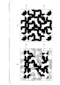
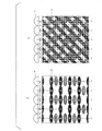
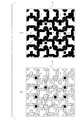
また、海外の点位相変調(Dot phase modulation)の一例としては、アストロン・デザイン社(オランダ)のイソグラム(Isogram)がある(例えば、非特許文献1340頁参照)。これは、図27(a)に示された印刷物のように、一見して均一な濃度を有する平坦な模様の中に、拡大すると図27(b)に示されたような微細な網点の位相によって不可視画像が施され、印刷物上に専用のシートを重ねると、図27(c)又は図27(d)に示されるようにネガポジ状のどちらかに可視画像化されたものである。しかし、これは、均一な濃度を有する平坦な模様故に、鮮明に画像を発現させることができない。 As an example of overseas dot phase modulation, there is an isogram from Astron Design (Netherlands) (for example, see page 1340 of Non-Patent Document). As shown in FIG. 27 (a), a fine halftone dot as shown in FIG. 27 (b) is obtained by enlarging a flat pattern having a uniform density at first glance. When an invisible image is applied according to the phase and a dedicated sheet is overlaid on the printed material, the image is formed into a negative-positive image as shown in FIG. 27 (c) or FIG. 27 (d). However, since this is a flat pattern having a uniform density, an image cannot be clearly expressed.
また、本願出願人等は、点位相変調(Dot phase modulation)を用いた印刷物に関する特許出願を行っている。これは、基材上に複数の等色の画素が規則的に配列されて二つの潜像模様が形成された潜像印刷物であって、複数の画素において、第1の方向に位相をずらして配列された第1の領域による第1の潜像模様(不可視画像)と、機能性を有するインキにより印刷された第2の領域による第2の潜像模様(不可視画像)とを有する(例えば、特許文献3参照)。 In addition, the applicant of the present application has filed a patent application relating to a printed matter using dot phase modulation. This is a latent image printed matter in which a plurality of pixels of the same color are regularly arranged on a substrate to form two latent image patterns, and the phases of the plurality of pixels are shifted in the first direction. A first latent image pattern (invisible image) formed by the arranged first regions, and a second latent image pattern (invisible image) formed by the second region printed by the functional ink (for example, (See Patent Document 3).
線位相変調(Line phase modulation)の一例としては、基材上に、線部と非線部を有し、同一ピッチ及び幅から成る万線パターンに対し、万線位相を2分の1ピッチずらして形成された潜像部を備えている複数種の潜像万線パターンが、それぞれ異なる角度で重ね合わされて印刷された潜像を有する印刷物であって、複数種の潜像万線パターンがそれぞれ色違いであることを特徴とする印刷物と、印刷物の万線パターンと同一ピッチのフィルムを複数種の不可視画像に重ね合わせることにより潜像部を可視画像化されたものがある(例えば、特許文献4参照)。 As an example of line phase modulation, the line phase is shifted by a half pitch with respect to the line pattern having the line part and the non-line part on the base material and having the same pitch and width. A plurality of types of latent image line patterns each having a latent image portion formed in this manner are printed matter having latent images printed by being superimposed at different angles. There are prints characterized by different colors, and a latent image portion made visible by superimposing a plurality of invisible images on a film having the same pitch as the line pattern of the print (for example, Patent Documents) 4).
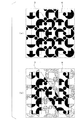
また、海外の線位相変調(Line phase modulation)を用いた印刷物には、ユラ社(ハンガリー)のHIT(Hidden Image Technology)がある(非特許文献1341頁参照)。図28(a)に示されたように、一見して均一な濃度を有する平坦な模様の中に、拡大すると図28(b)に示されたような微細な万線の位相によって不可視画像が施され、印刷物上に専用のシートを重ねると、図28(c)又は図28(d)に示されるようにネガポジ状のどちらかに可視画像化されている。なお、図28(a)の印刷物では通常視でも不可視画像が確認できてしまうおそれがあるため、図28(b)に示されたように、カムフラージュ模様として万線の一部の画線幅を変化させて可視画像を設けている。また、白抜き画線によって可視画像を設けても良い。ただし、このカムフラージュ模様は、専用のシートを重ねて不可視画像を可視画像化した際、カモフラージュ模様も可視画像として同時に発現しているので、不可視画像の発現時の視認性を阻害するという問題がある。 Moreover, HIT (Hidden Image Technology) of Yura (Hungary) is a printed material using overseas line phase modulation (see page 1341). As shown in FIG. 28A, when an image is enlarged in a flat pattern having a uniform density at first glance, an invisible image is formed due to the phase of fine lines as shown in FIG. When a dedicated sheet is superimposed on the printed material, a visible image is formed in either a negative or positive shape as shown in FIG. 28 (c) or FIG. 28 (d). In addition, in the printed matter of FIG. 28 (a), an invisible image may be confirmed even with normal viewing. Therefore, as shown in FIG. 28 (b), a part of the line width of the line is set as a camouflage pattern. A visible image is provided by changing. Moreover, you may provide a visible image with a white drawing line. However, this camouflage pattern has a problem that when the invisible image is made visible by overlapping a dedicated sheet, the camouflage pattern also appears as a visible image at the same time. .
一般的に、点位相変調(Dot phase modulation)又は線位相変調(Line phase modulation)により形成された模様は、平坦な形状となっている。 In general, a pattern formed by dot phase modulation or line phase modulation has a flat shape.
また、画像形成シート上に、単位ブロック内をm列n行に等形状分割した各々最小単位ブロックb1、b2、b3、b4、・・・を、それぞれ1単位画素g1、g2、g3、g4、・・・とする各々潜像画像G1、G2、G3、G4、・・・が形成され、その単位画素g1、g2、g3、g4、・・・は、万線本数1本分以上の万線により構成される万線パターンであって、ピッチp1、p2、p3、p4、・・・の各々万線ピッチpと、角度θ1、θ2、θ3、θ4・・・の各々万線角度θの万線により構成される異なる各々万線パターンのうち、いずれかの万線パターンにより構成された偽造防止用画像印刷物であり、1単位画素g1、g2、g3、g4、・・・を構成する万線パターンと、同一の万線ピッチp及び万線角度θの万線により構成されるそれぞれ異なる万線パターンを、透明シートに形成した顕像化用の万線シートを重ね合わせることで、潜像画像G1、G2、G3、G4、・・・を顕像化するようにした偽造防止用画像印刷物が提案されている(例えば、特許文献5参照)。 Further, on the image forming sheet, the minimum unit blocks b1, b2, b3, b4,... Obtained by equally dividing the unit block into m columns and n rows are respectively converted into 1 unit pixels g1, g2, g3, g4,. Are formed as latent image images G1, G2, G3, G4,..., And unit pixels g1, g2, g3, g4,. Are each a line pattern p of pitches p1, p2, p3, p4,... And a line angle θ of each of angles θ1, θ2, θ3, θ4. An anti-counterfeit image printed matter constituted by any one of the different line patterns constituted by lines, and each line constituting one unit pixel g1, g2, g3, g4,. With the pattern and the lines with the same line pitch p and line angle θ The latent image G1, G2, G3, G4,... Is visualized by superimposing the different line patterns formed on the transparent sheet on the transparent sheet. An anti-counterfeit image printed matter has been proposed (see, for example, Patent Document 5).
この特許文献5による偽造防止用画像印刷物は、各々の単位画素において万線パターンのピッチ及び角度を異ならせることにより、複数の潜像画像を顕像化するものではあるが、可視画像としては、一様な背景模様としか表現できず、更に潜像画像を顕像化するためには、その潜像画像を構成する単位画素の万線パターンに合ったピッチ及び角度を要する透明シートが必要となり、複数の判別具を用意しなければならないという問題があった。
上述した従来の印刷物では、潜像模様が平坦な濃度を有する印刷画線から成るため、鮮明に発現可能な不可視画像を形成することができなかった。 In the conventional printed matter described above, since the latent image pattern is formed of a printed image line having a flat density, an invisible image that can be clearly expressed cannot be formed.
また、何らかの可視画像を設けたとしても、特許文献2に記載された印刷物のように単純な白抜き画線から成るため、不可視画像を発現させた時の視認性を阻害するという問題があった。更に、特許文献5に記載された印刷物のように複数の判別具を必要とするものもあった。
In addition, even if some visible image is provided, the printed image described in
本発明は、上記事情にかんがみ、単一の判別具により鮮明な発現が可能な不可視画像を形成するとともに、不可視画像を発現させた時に可視画像によって視認性が阻害されない偽造防止用印刷物を提供することを目的とする。 In view of the above circumstances, the present invention provides an anti-counterfeit printed matter that forms an invisible image that can be clearly expressed with a single discriminator and that does not impair visibility by the visible image when the invisible image is expressed. For the purpose.
本発明による偽造防止用印刷物は、基材に、第1の方向に沿って、中心を境に対向するように配置された第1の画線及び第2の画線と、第1の方向と直交する第2の方向に沿って、中心を境に対向するように配置された第3の画線及び第4の画線とを有する画線要素が、一定のピッチで複数マトリクス状に配置されており、各々の画線要素における第1の画線と第2の画線とはネガポジの関係にあり、かつ、面積が同一であり、第1の画線により第1の不可視画像のポジ画像又はネガ画像が形成され、第2の画線により第1の不可視画像のネガ画像又はポジ画像が形成され、各々の画線要素における第3の画線と第4の画線とはネガポジの関係にあり、かつ、面積が同一であり、第3の画線により第2の不可視画像のポジ画像又はネガ画像が形成され、第4の画線により第2の不可視画像のネガ画像又はポジ画像が形成され、第1の画線、第2の画線、第3の画線及び第4の画線が存在しない領域で、かつ、第1の不可視画像を可視化する際に重ねる判別具の中心線上及び第2の不可視画像を可視化する際に重ねる判別具の中心線上からずれた位置に中心を有する第5の画線により可視画像が形成されたことを特徴とする偽造防止用印刷物である。 The printed matter for preventing forgery according to the present invention includes a first image line, a second image line, and a first direction, which are arranged on the base material so as to face the boundary along the first direction. Image line elements having a third image line and a fourth image line arranged so as to be opposed to the center along the second direction orthogonal to each other are arranged in a matrix at a constant pitch. The first image line and the second image line in each image line element are in a negative-positive relationship and have the same area, and the positive image of the first invisible image by the first image line. Alternatively, a negative image is formed, and a negative image or positive image of the first invisible image is formed by the second image line, and the third image line and the fourth image line in each image line element have a negative-positive relationship. And the area is the same, and the positive or negative image of the second invisible image is formed by the third image line. Made, by the fourth image line formed negative image or positive image of the second invisible image, the first image line, not the second image line, the third image line and the fourth image line exists A fifth image having a center in a region and at a position shifted from the center line of the discriminator superimposed when visualizing the first invisible image and the center line of the discriminator superimposed when visualizing the second invisible image. A printed matter for preventing forgery, wherein a visible image is formed by a line .
また、本発明の偽造防止用印刷物における画線要素は、正方形の形状を有し、一辺の長さが1mm以下であっても良い。 Further, the image line element in the forgery-preventing printed material of the present invention may have a square shape and a side length of 1 mm or less.
本発明の偽造防止用印刷物における第1の画線、第2の画線、第3の画線及び第4の画線は、それぞれ円形の形状又はそれぞれ多角形の形状を有することもできる。 The first image line, the second image line, the third image line, and the fourth image line in the anti-counterfeit printed matter of the present invention can each have a circular shape or a polygonal shape.
本発明の偽造防止用印刷物における第1の画線、第2の画線、第3の画線及び第4の画線は、それぞれ半円の形状を有し、第1の画線と第2の画線とが対向するように配置されて第1の画線及び第2の画線により一つの円を形成し、第3の画線と第4の画線とが対向するように配置されて第3の画線及び第4の画線により一つの円を形成し、第1の画線の2分の1と第3の画線の2分の1とが重複し、第1の画線の2分の1と第4の画線の2分の1とが重複し、第2の画線の2分の1と第3の画線の2分の1とが重複し、第2の画線の2分の1と第4の画線の2分の1とが重複することで、第1の画線、第2の画線、第3の画線及び第4の画線により一つの円を形成するものであっても良い。 The first image line, the second image line, the third image line, and the fourth image line in the anti-counterfeit printed matter of the present invention each have a semicircular shape, and the first image line and the second image line Are arranged so as to face each other and form a circle by the first and second lines, and the third and fourth lines are arranged to face each other. The third image line and the fourth image line form a circle, and half of the first image line and half of the third image line overlap, Half of the line and half of the fourth line overlap, half of the second line and half of the third line overlap, The second image line and the second image line are overlapped with each other so that the first image line, the second image line, the third image line, and the fourth image line A single circle may be formed.
本発明の偽造防止用印刷物における第1の画線、第2の画線、第3の画線及び第4の画線は、それぞれ二等辺三角形の形状を有し、第1の画線と第2の画線とが対向するように配置されて第1の画線及び第2の画線により一つの四角形を形成し、第3の画線と第4の画線とが対向するように配置されて第3の画線及び第4の画線により一つの四角形を形成し、第1の画線の2分の1と第3の画線の2分の1とが重複し、第1の画線の2分の1と第4の画線の2分の1とが重複し、第2の画線の2分の1と第3の画線の2分の1とが重複し、第2の画線の2分の1と第4の画線の2分の1とが重複することで、第1の画線、第2の画線、第3の画線及び第4の画線により一つの四角形を形成するものであっても良い。 The first image line, the second image line, the third image line, and the fourth image line in the anti-counterfeit printed matter of the present invention each have an isosceles triangle shape, and the first image line and the second image line The first image line and the second image line form a single quadrangle, and the third image line and the fourth image line are opposed to each other. The third image line and the fourth image line form a quadrangle, and one half of the first image line and one half of the third image line overlap, Half of the stroke and half of the fourth stroke overlap, half of the second stroke and half of the third stroke overlap, The first image line, the second image line, the third image line, and the fourth image line are obtained by overlapping one half of the second image line and one half of the fourth image line. May form one square.
本発明の偽造防止用印刷物は、第5の画線が画線要素の中心に配置され、第5の画線により第1の可視画像が形成され、第1の画線と第2の画線とが、第5の画線を間に対向するように配置され、第3の画線と第4の画線とが、第5の画線を間に対向するように配置され、第6の画線が画線要素の四隅に配置され、第6の画線により第2の可視画像が形成されているものであっても良い。 In the forgery prevention printed matter of the present invention, the fifth image line is arranged at the center of the image element, the first visible image is formed by the fifth image line, and the first image line and the second image line. Are arranged so as to face the fifth image line in between, and the third image line and the fourth image line are arranged so as to face the fifth image line in between, The image line may be arranged at the four corners of the image line element, and the second visible image may be formed by the sixth image line.
本発明の偽造防止用印刷物は、第1の画線、第2の画線、第3の画線、第4の画線、第5の画線及び第6の画線は光輝性材料を含むインキで印刷され、光輝性材料を有するインキで印刷された第5の画線及び/又は第6の画線上における少なくとも一部に、第5の画線及び/又は第6の画線と各々の大きさが同じ若しくは小さい画線面積からなる任意の有色インキで印刷された第7の画線を更に備え、第7の画線によって第3の可視画像が形成されているものであっても良い。 In the forgery-preventing printed matter of the present invention, the first image line, the second image line, the third image line, the fourth image line, the fifth image line, and the sixth image line contain a glittering material. The fifth image line and / or the sixth image line and at least part of the fifth image line and / or the sixth image line printed with ink and printed with ink having a glittering material, The image forming apparatus may further include a seventh image line printed with any colored ink having the same or smaller image area, and the third visible image may be formed by the seventh image line. .
本発明の偽造防止用印刷物は、第1の画線、第2の画線、第3の画線、第4の画線、第5の画線及び/又は第6の画線は光輝性材料を含むインキで印刷され、第1の画線、第2の画線、第3の画線、第4の画線、第5の画線及び/又は第6の画線上における少なくとも一部の画線上に、無色透明材料を用いてベタ刷りにより所望の模様を形成されているものであっても良い。 In the printed matter for preventing forgery of the present invention, the first image line, the second image line, the third image line, the fourth image line, the fifth image line and / or the sixth image line are glittering materials. At least a portion of the image on the first image line, the second image line, the third image line, the fourth image line, the fifth image line, and / or the sixth image line. On the line, a desired pattern may be formed by solid printing using a colorless and transparent material.
本発明による偽造防止用印刷物は、基材に、中心を境に対向するように配置された第1の画線及び第2の画線から成る第1の画線要素が、一定の方向に沿って規則的に一定ピッチで複数配置された第1の不可視画像要素と、中心を境に対向するように配置された第3の画線及び第4の画線から成る第2の画線要素が、一定の方向と同一方向であって、かつ、一定ピッチと同じピッチであり、規則的に複数配置された第2の不可視画像要素とが交互に複数配列されており、第1の不可視画像要素と第2の不可視画像要素は、一定の方向に沿って一定のピッチの1/4ピッチずれて形成され、各々の第1の画線要素における第1の画線と第2の画線とはネガポジの関係にあり、かつ、面積及び色が同一であり、第1の画線により第1の不可視画像のポジ画像又はネガ画像が形成され、第2の画線により第1の不可視画像のネガ画像又はポジ画像が形成され、各々の第2の画線要素における第3の画線と第4の画線とはネガポジの関係であって、かつ、面積及び色が同一であり、第3の画線により第2の不可視画像のポジ画像又はネガ画像が形成され、第4の画線により第2の不可視画像のネガ画像又はポジ画像が形成されていることを特徴とする偽造防止用印刷物である。 In the forgery-preventing printed matter according to the present invention, the first image element composed of the first image line and the second image line arranged on the base so as to face the center is located along a certain direction. A plurality of first invisible image elements arranged regularly at a constant pitch, and a second image element composed of a third image line and a fourth image line arranged so as to face the center. A plurality of second invisible image elements that are arranged in the same direction as the constant direction and the same pitch as the constant pitch, and a plurality of regularly arranged second invisible image elements. And the second invisible image element are formed by shifting by a quarter pitch of a certain pitch along a certain direction, and the first image line and the second image line in each first image line element are The first invisible image has a negative-positive relationship, the same area and color, and the first image line. A positive image or a negative image is formed, and a negative image or a positive image of the first invisible image is formed by the second image line, and the third image line and the fourth image line in each second image element. Is a negative-positive relationship, and has the same area and color, the positive image or negative image of the second invisible image is formed by the third image line, and the second invisible image is formed by the fourth image line. An anti-counterfeit printed matter in which a negative image or a positive image of an image is formed.
また、本発明の偽造防止用印刷物は、第1の画線要素のピッチ及び第2の画線要素のピッチが1mm以下であることを特徴とする。 In the forgery-preventing printed matter of the present invention, the pitch of the first image element and the pitch of the second image element are 1 mm or less.
また、本発明の偽造防止用印刷物は、第1の画線要素を構成する第1の画線と第2の画線及び第2の画線要素を構成する第3の画線及び第4の画線が、互いに形状が同一であることを特徴とする。 The printed matter for preventing forgery of the present invention includes a first image line, a second image line, and a third image line forming the second image element, and a fourth image line forming the first image element. The image lines are characterized by having the same shape.
また、本発明の偽造防止用印刷物は、第1の画線、第2の画線、第3の画線及び第4の画線の形状及び色が、同一であることを特徴とする。 In the forgery-preventing printed matter of the present invention, the first image line, the second image line, the third image line, and the fourth image line have the same shape and color.
また、本発明の偽造防止用印刷物は、第1の画線と前記第2の画線から成る第1の画線要素と、第3の画線と第4の画線から成る第2の画線要素の色が異なることを特徴とする。 The forgery-preventing printed material according to the present invention includes a first image element composed of a first image line and the second image line, and a second image composed of a third image line and a fourth image line. The line elements are different in color.
また、本発明の偽造防止用印刷物は、第1の不可視画像要素及び第2の不可視画像要素において、第1の画線、第2の画線、第3の画線及び第4の画線の一部の画線と重複する位置に第5の画線が配置され、第5の画線は、第1の画線、第2の画線、第3の画線及び第4の画線と面積が同一か、又は大きく、第5の画線により可視画像が形成されていることを特徴とする。 In addition, the forgery-preventing printed matter of the present invention includes a first image line, a second image line, a third image line, and a fourth image line in the first invisible image element and the second invisible image element. The fifth image line is arranged at a position overlapping with some image lines, and the fifth image line includes the first image line, the second image line, the third image line, and the fourth image line. The area is the same or large, and a visible image is formed by the fifth image line.
また、本発明の偽造防止用印刷物は、第5の画線の色濃度は、第1の画線、第2の画線、第3の画線及び第4の画線の色濃度と同一か、又は低いことを特徴とする。 In the forgery-preventing printed matter of the present invention, the color density of the fifth image line is the same as the color densities of the first image line, the second image line, the third image line, and the fourth image line. Or low.
また、本発明の偽造防止用印刷物は、第5の画線は、第1の画線、第2の画線、第3の画線及び第4の画線と同じ形状であることを特徴とする。 In the forgery prevention printed matter of the present invention, the fifth image line has the same shape as the first image line, the second image line, the third image line, and the fourth image line. To do.
また、本発明の偽造防止用印刷物における第5の画線が、第1の画線、第2の画線、第3の画線及び第4の画線の一部の画線と重複する位置に配置されているというのは、第1の不可視画像要素及び第2の不可視画像要素を規則的に複数配列する際に、本来配置されるべく一部の画線の位置に、一部の画線が配置されずに第5の画線のみが配置されている又は一部の画線が配置された上に、第5の画線が重ね刷りして配置されたことを特徴とする。 Further, the fifth image line in the forgery-preventing printed matter of the present invention overlaps with the first image line, the second image line, the third image line, and a part of the fourth image line. Is arranged at a position of a part of the line to be originally arranged when a plurality of the first invisible image elements and the second invisible image elements are regularly arranged. Only the fifth image line is arranged without arranging the line, or a part of the image line is arranged, and the fifth image line is overprinted.
また、本発明の偽造防止印刷物における第1乃至第4の画線又は第1乃至第5の画線は光輝性材料を含むインキで印刷され、光輝性材料を有するインキで印刷された第1乃至第4の画線又は第1乃至第5の画線から選択される少なくとも一部の画線上に、第1乃至第4又は第1乃至第5の画線と各々の大きさが同じ若しくは小さい画線面積から成る任意の有色インキで印刷された第6の画線を更に備え、第6の画線によって第3の可視画像が形成されていることを特徴としている。 In addition, the first to fourth lines or the first to fifth lines in the anti-counterfeit printed matter of the present invention are printed with ink containing a glittering material, and are printed with ink having a glittering material. An image having the same or smaller size as each of the first to fourth or first to fifth image lines on at least a part of the image lines selected from the fourth image line or the first to fifth image lines. A sixth image line printed with an arbitrary colored ink having a line area is further provided, and a third visible image is formed by the sixth image line.
また、本発明の偽造防止印刷物における第1乃至第4の画線又は第1乃至第5の画線は光輝性材料を含むインキで印刷され、第1乃至第4の画線又は第1乃至第5の画線上における少なくとも一部の画線上に、無色透明材料を用いてベタ刷りにより所望の模様が形成されていることを特徴としている。
In addition, the first to fourth image lines or the first to fifth image lines in the forgery-preventing printed matter of the present invention are printed with ink containing a glittering material, and the first to fourth image lines or the first to first image lines are printed. A desired pattern is formed on at least a part of the
本発明は、基材に、第1の方向に沿って、中心を境に対向するように(隙間なく)配置された第1の画線及び第2の画線から成るunitが、所定の領域に、規則的に一定ピッチで複数配置され、複数配置された各々のunitにおいて、第1の画線と第2の画線とはネガポジの関係にあり、かつ、面積及び色が同一であり、第1の画線と第2の画線において、一方をオン、他方をオフとの組み合わせにより不可視画像が形成され、不可視画像を形成するために配置された第1の画線及び第2の画線のうち、複数隣接して配置されたunitのうち、オフとなっている部分が隣接して配置されている位置に、所定の領域における濃度の不均衡を緩和するため、第1の画線及び第2の画線における略半分の画線面積率、かつ、略同色である第3の画線が、第1の画線と第2の画線の境界線を中心として配置されて成る偽造防止用印刷物である。 According to the present invention, a unit composed of a first image line and a second image line arranged on a base material so as to be opposed to each other with no gap along the first direction has a predetermined region. In addition, a plurality of units are regularly arranged at a constant pitch, and in each of the units arranged in a plurality, the first image line and the second image line are in a negative-positive relationship and have the same area and color. An invisible image is formed by combining one of the first image line and the second image line with one on and the other image off, and the first image line and the second image arranged to form the invisible image. In order to alleviate the density imbalance in the predetermined region at the position where the off part of the units arranged adjacent to each other is arranged adjacent to the first drawing line, And a third half-line area ratio and substantially the same color in the second line. Streak is a anti-counterfeit printed matter consisting disposed around the boundary of the first image line and the second image line.
本発明は、unit同士の一定のピッチが、1mm以下であることを特徴とする偽造防止用印刷物である。 The present invention is the anti-counterfeit printed matter, wherein a constant pitch between the units is 1 mm or less.
本発明は、第1の画線及び/又は第2の画線が本来不可視画像を形成する一部の画線の位置に、第4の画線が重ね刷りにより又は前記第4の画線のみが配置され、第4の画線は、第1の画線及び第2の画線と面積が同一又は大きく、第4の画線により可視画像が形成されていることを特徴とする偽造防止用印刷物である。 According to the present invention, the first image line and / or the second image line is formed at the position of a part of the image line that originally forms an invisible image, and the fourth image line is overprinted or only the fourth image line. And the fourth image line has the same or larger area as the first image line and the second image line, and a visible image is formed by the fourth image line. It is printed matter.
本発明における第4の画線の色濃度は、第1の画線及び第2の画線の色濃度と同一か、又は低いことを特徴とする偽造防止用印刷物である。 In the present invention, the color density of the fourth image line is the same or lower than that of the first image line and the second image line.
本発明は、第1の画線、第2の画線、第3の画線、第4の画線は光輝性材料を含むインキで印刷され、第1の画線、第2の画線、第3の画線、第4の画線の画線の一部の画線上に、無色透明材料を用いてベタ刷りにより所望の模様を形成することを特徴とする偽造防止用印刷物である。 In the present invention, the first image line, the second image line, the third image line, and the fourth image line are printed with ink containing a glittering material, and the first image line, the second image line, A forgery-preventing printed matter characterized in that a desired pattern is formed by solid printing on a part of the third and fourth image lines using a colorless and transparent material.
本発明は、基材に、第1の方向に沿って、中心を境に対向するように配置された第1の画線及び第2の画線と、第1の方向に直行する第2の方向に沿って、中心を境に対向するように配置された第3の画線及び第4の画線とを有するunitが、所定の領域に、規則的に一定ピッチで複数配置され、複数配置された各々のunitにおいて、第1の画線と第2の画線とはネガポジの関係にあり、かつ、第3の画線と第4の画線とはネガポジの関係にあり、第1の画線、第2の画線、第3の画線及び第4の画線は、面積及び色が同一であり、第1の画線と第2の画線において、一方をオン、他方をオフとの組み合わせにより第1の不可視画像が形成され、 第1の不可視画像を形成するために配置された第1の画線及び第2の画線のうち、複数隣接して配置されたunitのうち、オフとなっている部分が隣接して配置されている位置に、所定の領域における濃度の不均衡を緩和するために、第1の画線及び第2の画線における略半分の画線面積率を有する第5の画線が、unit同士の境界線を中心として配置され、第3の画線と第4の画線において、一方をオン、他方をオフとの組み合わせにより第2の不可視画像が形成され、第2の不可視画像を形成するために配置された第3の画線及び第4の画線のうち、複数隣接して配置されたunitのうち、オフとなっている部分が隣接して配置されている位置に、所定の領域における濃度の不均衡を緩和するために、第3の画線及び第4の画線における略半分の画線面積率を有する第6の画線が、unit同士の境界線を中心として配置されて成る偽造防止用印刷物である。 According to the present invention, a first image line and a second image line that are arranged on the base material so as to face the center along the first direction and the second image line that is orthogonal to the first direction. A plurality of units having a third image line and a fourth image line arranged so as to be opposed to the center along the direction are regularly arranged in a predetermined area at a constant pitch. In each unit, the first image line and the second image line are in a negative-positive relationship, and the third image line and the fourth image line are in a negative-positive relationship. The drawing line, the second drawing line, the third drawing line, and the fourth drawing line have the same area and color. One of the first drawing line and the second drawing line is turned on, and the other is turned off. A first invisible image is formed by a combination of and a plurality of first and second lines arranged to form the first invisible image. In order to alleviate the density imbalance in a predetermined area at the position where the off part of the units arranged in contact is adjacent, the first image line and the second image A fifth drawing line having a drawing line area ratio that is substantially half of the drawing line is arranged around the boundary line between the units, and one of the third drawing line and the fourth drawing line is turned on and the other is turned off. A second invisible image is formed by the combination of, among the units arranged adjacent to each other among the third image line and the fourth image line arranged to form the second invisible image, In order to alleviate the density imbalance in the predetermined area at the position where the part that is off is adjacently arranged, the area ratio of the half of the third and fourth lines is approximately half. The 6th drawing line with a centered on the boundary line between units This is an anti-counterfeit printed matter.
本発明は、unitは正方形の形状を有し、一辺の長さが1mm以下であることを特徴とする偽造防止用印刷物である。 The present invention is the anti-counterfeit printed matter, wherein the unit has a square shape, and the length of one side is 1 mm or less.
本発明におけるunitは、第1の画線、第2の画線、第3の画線及び第4の画線が存在しない領域に配置された第7の画線を更に有し、第7の画線により可視画像が形成されていることを特徴とする偽造防止用印刷物である。 The unit in the present invention further includes a seventh image line arranged in a region where the first image line, the second image line, the third image line, and the fourth image line do not exist. A printed matter for preventing counterfeiting, wherein a visible image is formed by an image line.
本発明における第1の画線、第2の画線、第3の画線及び第4の画線は、それぞれ円形又は多角形の形状を有することを特徴とする偽造防止用印刷物である。 The first image line, the second image line, the third image line, and the fourth image line in the present invention are forgery-preventing printed materials characterized by having a circular or polygonal shape, respectively.
本発明における第1の画線、第2の画線、第3の画線及び第4の画線は、それぞれ半円の形状又は二等辺三角形を有し、第1の画線と第2の画線が半円の形状のときには、第1の画線と第2の画線により一つの円が形成され、第1の画線と第2の画線が二等辺三角形のときには、第1の画線と第2の画線により一つの四角形が形成され、第3の画線と第4の画線が半円の形状のときには、第3の画線と第4の画線により一つの円が形成され、第3の画線と第4の画線が二等辺三角形のときには、第3の画線と第4の画線により一つの四角形が形成され、第1の画線の2分の1と第3の画線の2分の1とが重複し、第1の画線の2分の1と第4の画線の2分の1とが重複し、第2の画線の2分の1と第3の画線の2分の1とが重複し、第2の画線の2分の1と第4の画線の2分の1とが重複することで、第1の画線、第2の画線、第3の画線及び第4の画線により一つの円又は一つの四角形が形成されていることを特徴とする偽造防止用印刷物である。
The first image line, the second image line, the third image line, and the fourth image line in the present invention each have a semicircular shape or an isosceles triangle, and the first image line and the second image line When the image line is a semicircle, a first circle is formed by the first image line and the second image line, and when the first image line and the second image line are isosceles triangles, When the drawing line and the second drawing line form a quadrangle, and the third drawing line and the fourth drawing line have a semicircular shape, one circle is formed by the third drawing line and the fourth drawing line. Is formed, and when the third and fourth image lines are isosceles triangles, a single quadrangle is formed by the third and fourth image lines, which is half of the first image line. 1 and half of the third drawing line overlap, half of the first drawing line and half of the fourth drawing line overlap, and 2 of the second drawing line 1st and half of the 3rd line overlap and the
本発明は、第7の画線がunitの中心に配置され、第7の画線により第1の可視画像が形成され、第1の画線と第2の画線とが、第7の画線を挟んで対向するように配置され、かつ、第3の画線と第4の画線とが、第7の画線を挟んで対抗するように配置され、さらに、第8の画線がunitの四隅に配置され、第8の画線により第2の可視画像が形成されていることを特徴とする偽造防止用印刷物である。 In the present invention, the seventh image line is arranged at the center of the unit, the first visible image is formed by the seventh image line, and the first image line and the second image line are the seventh image line. Arranged so as to face each other across the line, the third image line and the fourth image line are arranged so as to face each other across the seventh image line, and the eighth image line The anti-counterfeit printed matter is characterized in that the second visible image is formed by the eighth image line disposed at the four corners of the unit.
本発明は、第1の画線と第2の画線が、第1の方向に隣接して配置されて第1の不可視画像を形成するために本来存在する位置、及び第3の画線と第4の画線が、第2の方向に隣接して配置されて第2の不可視画像を形成するために本来存在する位置において、所定の領域における濃度の不均衡を緩和するために、第1の画線、第2の画線、第3の画線及び第4の画線における略半分の画線面積率を有する第9の画線が、unitの中心に配置されたことを特徴とする偽造防止用印刷物である。 In the present invention, the first image line and the second image line are arranged adjacent to each other in the first direction to form a first invisible image, and the third image line. In order to alleviate the density imbalance in the predetermined area at the position where the fourth image line is originally located adjacent to the second direction to form the second invisible image, The ninth image line having a substantially half of the image line area ratio of the image line, the second image line, the third image line, and the fourth image line is arranged at the center of the unit. This is a printed matter for preventing counterfeiting.
本発明は、第1の画線、第2の画線、第3の画線及び第4の画線が存在しないunitにおいて、unitの中心に配置された第9の画線を更に有し、第9の画線が、第1の画線、第2の画線、第3の画線又は第4の画線と略同一の画線面積であることを特徴とする偽造防止用印刷物である。 The present invention further includes a ninth image line arranged at the center of the unit in the unit where the first image line, the second image line, the third image line, and the fourth image line do not exist, The ninth image line is an anti-counterfeit printed matter having an image area substantially the same as the first image line, the second image line, the third image line, or the fourth image line. .
本発明における第1の画線、第2の画線、第3の画線、第4の画線、第5の画線、第6の画線、第7の画線、第8の画線及び第9の画線は、光輝性材料を含むインキで印刷され、光輝性材料を有するインキで印刷された第7の画線及び/又は第8の一部の画線上に、第7の画線及び/又は第8と同じ若しくは小さい画線面積から成る任意の有色インキで印刷された第10の画線を更に備え、
第10の画線によって第3の可視画像が形成されていることを特徴とする偽造防止用印刷物である。The first image line, the second image line, the third image line, the fourth image line, the fifth image line, the sixth image line, the seventh image line, and the eighth image line in the present invention. And the ninth image line is printed with an ink containing a glittering material, and the seventh image line and / or the eighth partial image printed with the ink having the glittering material are printed on the seventh image line. A tenth line printed with any colored ink consisting of the line and / or the same or smaller line area as the eighth;
A forgery-preventing printed matter, wherein a third visible image is formed by a tenth image line.
本発明における第1の画線、第2の画線、第3の画線、第4の画線、第5の画線、第6の画線、第7の画線、第8の画線及び第9の画線は、光輝性材料を含むインキで印刷され、第1の画線、第2の画線、第3の画線、第4の画線、第5の画線、第6の画線、第7の画線、第8の画線及び第9の画線の一部の画線上に、無色透明材料を用いてベタ刷りにより所望の模様を形成することを特徴とする偽造防止用印刷物である。 The first image line, the second image line, the third image line, the fourth image line, the fifth image line, the sixth image line, the seventh image line, and the eighth image line in the present invention. And the ninth image line are printed with ink containing a glittering material, and the first image line, the second image line, the third image line, the fourth image line, the fifth image line, the sixth image line, Forgery characterized in that a desired pattern is formed by solid printing using a colorless transparent material on a part of the image lines of No. 7, No. 7, No. 8, and No. 9 Print for prevention.
本発明は、基材に、第1の方向に沿って配置された第1の画線と、第1の画線と同一方向に配置された第2の画線が一対となって形成された第1の画線要素が一定のピッチで複数配置され、第1の方向と異なる方向である第2の方向に沿って配置された第3の画線と、第3の画線と同一方向に配置された第4の画線が一対となって形成された第2の画線要素が一定のピッチで複数配置され、第1の方向及び第2の方向と異なる方向である第3の方向に沿って配置された第5の画線と、第5の画線と同一方向に配置された第6の画線が一対となって形成された第3の画線要素が一定のピッチで複数配置され、一対となって形成された第1の画線と第2の画線の面積が同一であり、一対となって形成された第3の画線と第4の画線の面積が同一であり、一対となって形成された第5の画線と第6の画線の面積が同一であり、第1の画線要素が形成された第1の方向を0度とした場合に、第2の画線要素が配列される第2の方向が60度であり、第3の画線要素が配列される第3の方向が120度で形成され、第1の画線と第2の画線からなる各々の第1の画線要素はオンオフの関係によって第1の不可視画像を形成し、第1の画線によって第1の不可視画像のポジ画像又はネガ画像の一方が形成され、第2の画線によって第1の不可視画像のネガ画像又はポジ画像の他方が形成され、第3の画線と第4の画線からなる各々の第2の画線要素はオンオフの関係によって第2の不可視画像を形成し、第3の画線によって第2の不可視画像のポジ画像又はネガ画像の一方が形成され、第4の画線によって第2の不可視画像のネガ画像又はポジ画像の他方が形成され、第5の画線と第6の画線からなる各々の第3の画線要素はオンオフの関係によって第3の不可視画像を形成し、第5の画線によって第3の不可視画像のポジ画像又はネガ画像の一方が形成され、第6の画線によって第3の不可視画像のネガ画像又はポジ画像の他方が形成され、第1の画線、第2の画線、第3の画線、第4の画線、第5の画線及び第6の画線が存在しない領域で、かつ、第1の不可視画像を可視化する際に重ねる判別具の中心線上、第2の不可視画像を可視化する際に重ねる判別具の中心線上及び第3の不可視画像を可視化する際に重ねる判別具の中心線上からずれた位置に中心を有する第7の画線により第1の可視画像が形成されたことを特徴とする偽造防止用印刷物である。 The present invention, on a substrate, a first image lines arranged along a first direction, the second image lines disposed in a first image line and the same direction are formed is a pair A plurality of first drawing elements are arranged at a constant pitch, and a third drawing line arranged along a second direction that is different from the first direction, and in the same direction as the third drawing line. A plurality of second image line elements formed with a pair of arranged fourth image lines are arranged at a constant pitch, in a third direction that is different from the first direction and the second direction. A plurality of third image line elements formed by a pair of a fifth image line arranged along with a sixth image line arranged in the same direction as the fifth image line are arranged at a constant pitch. The area of the first image line and the second image line formed as a pair is the same, and the area of the third image line and the fourth image line formed as a pair are the same. Ri, the area of the fifth image line and the sixth image lines formed becomes a pair are identical, when the first direction in which the first image line element is formed as 0 degrees, the The second direction in which the second line element is arranged is 60 degrees, the third direction in which the third line element is arranged is 120 degrees, and the first line and the second line are formed. Each first line element formed of lines forms a first invisible image according to an on / off relationship, and the first line forms one of a positive image or a negative image of the first invisible image, The negative image of the first invisible image or the positive image is formed by the image line, and each second image element composed of the third image line and the fourth image line has the second on-off relationship. An invisible image is formed, and a positive image or a negative image of the second invisible image is formed by the third image line, and the fourth image is formed. To form the other of the negative image or the positive image of the second invisible image, and each third image element composed of the fifth image line and the sixth image line changes the third invisible image according to the on / off relationship. Forming a positive image or negative image of the third invisible image by the fifth image line, and forming a negative image or positive image of the third invisible image by the sixth image line . The first invisible image is visualized in a region where the first image line, the second image line, the third image line, the fourth image line, the fifth image line, and the sixth image line do not exist. Centered on the center line of the discriminator to be overlapped, on the center line of the discriminator to be overlapped when visualizing the second invisible image, and on the center line of the discriminator to be overlapped when visualizing the third invisible image False, characterized in that the first visible image is formed by the seventh image line It is a printed matter for preventing manufacturing.
また、本発明は、前記第1の画線、前記第2の画線、前記第3の画線、前記第4の画線、前記第5の画線及び前記第6の画線の形状及び色が同一であることを特徴とする偽造防止用印刷物である。 The present invention also provides the shapes of the first image line, the second image line, the third image line, the fourth image line, the fifth image line, and the sixth image line, and It is a forgery-preventing printed matter characterized by having the same color.
また、本発明は、前記第1の画線と前記第2の画線から成る第1の画線要素と、前記第3の画線と前記第4の画線から成る第2の画線要素と、前記第5の画線及び前記第6の画線から成る第3の画線要素の色が互いに異なることを特徴とする偽造防止用印刷物である。 The present invention also provides a first image element composed of the first image line and the second image line, and a second image element composed of the third image line and the fourth image line. And the third image element composed of the fifth image line and the sixth image line are different in color from each other.
また、本発明は、前記第1の画線、前記第2の画線、前記第3の画線、前記第4の画線、前記第5の画線及び前記第6の画線は、光輝性材料を含むインキで印刷され、 前記第1の画線、前記第2の画線、前記第3の画線、前記第4の画線、前記第5の画線及び前記第6の画線の少なくとも一部の画線上に、無色透明材料を用いてベタ刷りにより所望の模様を形成することを特徴とする偽造防止用印刷物である。 In the present invention, the first image line, the second image line, the third image line, the fourth image line, the fifth image line, and the sixth image line are bright. The first image line, the second image line, the third image line, the fourth image line, the fifth image line, and the sixth image line. A forgery-preventing printed matter characterized in that a desired pattern is formed by solid printing on at least a part of the image lines of a transparent and colorless material.
また、本発明は、前記第1の画線、前記第2の画線、前記第3の画線、前記第4の画線、前記第5の画線、前記第6の画線及び前記第7の画線が存在しない領域で、かつ、前記第1の不可視画像を可視化する際に重ねる判別具の中心線上、前記第2の不可視画像を可視化する際に重ねる判別具の中心線上及び前記第3の不可視画像を可視化する際に重ねる判別具の中心線上からずれた位置に中心を有する第8の画線により第2の可視画像が形成されたことを特徴とする偽造防止用印刷物である。
The present invention also provides the first image line, the second image line, the third image line, the fourth image line, the fifth image line, the sixth image line, and the first image line. 7 on the center line of the discriminating tool to be overlapped when visualizing the first invisible image, the center line of the discriminating tool to be overlapped when visualizing the second invisible image, and the
また、本発明は、前記第7の画線及び/又は前記第8の画線は、前記第1の画線、前記第2の画線、前記第3の画線、前記第4の画線、前記第5の画線及び前記第6の画線のいずれかの画線で配列された六角形配列内又は三角形配列内の中心に配置されて形成されていることを特徴とする偽造防止用印刷物である。 According to the present invention, the seventh image line and / or the eighth image line are the first image line, the second image line, the third image line, and the fourth image line. Forgery prevention characterized by being arranged in the center of a hexagonal array or a triangular array arranged by any one of the fifth and sixth lines It is printed matter.
また、本発明における前記第1の画線、前記第2の画線、前記第3の画線、前記第4の画線、前記第5の画線及び前記第6の画線は、それぞれ円形の形状、それぞれ半円形以下の形状、それぞれ多角形の形状を有することを特徴とする偽造防止用印刷物である。 In the present invention, the first image line, the second image line, the third image line, the fourth image line, the fifth image line, and the sixth image line are each circular. The anti-counterfeit printed matter is characterized by having a shape of a half-circle or less, a polygonal shape, respectively.
また、本発明における前記第7の画線及び/又は前記第8の画線は、それぞれ円形の形状、それぞれ多角形の形状を有することを特徴とする偽造防止用印刷物である。 The seventh image line and / or the eighth image line in the present invention are forgery-preventing printed materials characterized by having a circular shape and a polygonal shape, respectively.
また、本発明における前記第7の画線及び前記第8の画線は、光輝性材料を含むインキで印刷され、前記第7の画線及び前記第8の画線の少なくとも一部の画線上に、無色透明材料を用いてベタ刷りにより所望の模様を形成することを特徴とする偽造防止用印刷物である。 Further, the seventh image line and the eighth image line in the present invention are printed with ink containing a glittering material, and are on at least part of the image lines of the seventh image line and the eighth image line. In addition, it is a forgery-preventing printed matter characterized in that a desired pattern is formed by solid printing using a colorless transparent material.
また、本発明は、前記第1の画線、前記第2の画線、前記第3の画線、前記第4の画線、前記第5の画線及び前記第6の画線は、光輝性材料を含むインキで印刷され、前記第7の画線及び/又は前記第8の画線の一部の画線上に、前記第7の画線及び/又は前記第8の画線と同じ若しくは小さい画線面積から成る任意の有色インキで印刷された第9の画線を更に備え、前記第9の画線によって第3の可視画像が形成されていることを特徴とする偽造防止用印刷物である。 In the present invention, the first image line, the second image line, the third image line, the fourth image line, the fifth image line, and the sixth image line are bright. Printed with an ink containing a functional material, and is the same as the seventh image line and / or the eighth image line on the seventh image line and / or a partial image line of the eighth image line, or An anti-counterfeit printed matter, further comprising a ninth image line printed with an arbitrary colored ink having a small image area, wherein a third visible image is formed by the ninth image line. is there.
本発明の偽造防止用印刷物によれば、単一の判別具により鮮明な発現が可能な不可視画像が形成されるとともに、不可視画像を発現させた時に可視画像によって視認性が阻害されず、印刷再現上の不具合を解消した偽造防止用印刷物が提供される。 According to the anti-counterfeit printed matter of the present invention, an invisible image that can be clearly expressed is formed by a single discriminator, and the visibility is not hindered by the visible image when the invisible image is expressed, and the print reproduction An anti-counterfeit printed matter that solves the above problems is provided.
以下、本発明の実施の形態1〜23による偽造防止用印刷物について、図面を用いて説明する。しかし、本発明は、以下に述べる実施の形態1〜23に限定されるものではなく、特許請求の範囲に記載された技術的範囲内であれば、その他の様々な変形が含まれる。
Hereinafter, forgery prevention printed matter according to
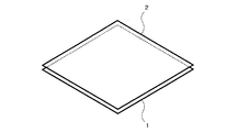
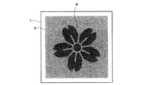
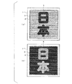
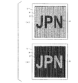
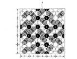
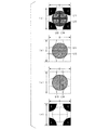
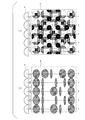
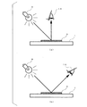
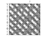
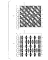
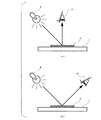
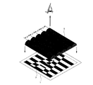
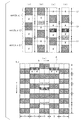
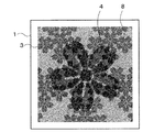
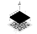
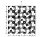
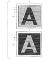
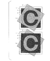
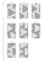
本発明の実施の形態1〜3による偽造防止用印刷物は、図1に示されたように、印刷物1に判別具2を重ね合わせることにより、容易に不可視画像を発現させて真偽性を判別することができるものである。判別具2は、透明性を有するフィルタに複数の直線が万線状に一方向に沿って形成された万線フィルタ又はレンチキュラーレンズ等である。印刷物1の印刷模様3を通常の可視条件において目視により観察すると、図2に示されたように、任意の図形及び文字等から成る模様4が視認される。そして、印刷物1上に判別具2を所定の角度(これを0度とする)を持って重ね合わせると、図3(a)又は図3(b)に示されたような第1の不可視画像5が可視画像となって発現する。また、印刷物1上に判別具2を所定の角度に対して90度を成す角度を持って重ね合わせると、図4(a)又は図4(b)に示されたような第2の不可視画像6が可視画像となって発現する。図3(a)又は図3(b)並びに図4(a)又は図4(b)に示されるようにネガポジ状のどちらかに見えるのは、判別具2と印刷物1との間の相対的な位置によって生ずるものであり、本発明の効果の範囲内である。
As shown in FIG. 1, the anti-counterfeit printed matter according to the first to third embodiments of the present invention easily discriminates authenticity by easily displaying an invisible image by overlaying the
(1)実施の形態1
本発明の実施の形態1による偽造防止用印刷物について説明する。(1)
A forgery prevention printed matter according to
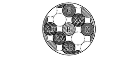
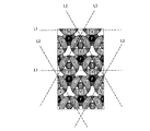
図5に、本実施の形態1における印刷物に対する印刷模様の一画線の構成を部分的に拡大して示す。ここで、縦横の寸法Sは、例えば、340μmというように1mm以下の大きさである。このような画線が、印刷物の表面上においてマトリクス状に規則的に配置される。各画線は、少なくとも三つ以上の画線要素を備えている。画線Aと画線A’とは、対を成しており、相互にネガポジの関係にある。このネガポジの関係とは、例えば、一方が黒(オン)のときは他方は白(オフ)、一方が有着色のときは他方は無着色であり、双方ともに黒又は双方ともに白であることがないということである。そして、画線Aと画線A’とは、面積が同一である。このような画線Aと画線A’とが存在することで通常の可視条件下では視認されず、画線Aのみにより第1の不可視画像(ネガ又はポジ)、画線A’のみにより第1の不可視画像(ポジ又はネガ)がそれぞれ形成されている。 FIG. 5 shows a partially enlarged configuration of one stroke of the printed pattern for the printed matter in the first embodiment. Here, the vertical and horizontal dimensions S are 1 mm or less, for example, 340 μm. Such image lines are regularly arranged in a matrix on the surface of the printed material. Each drawing line includes at least three drawing line elements. The image line A and the image line A ′ are paired and have a negative-positive relationship with each other. The negative / positive relationship is, for example, that when one is black (on), the other is white (off), and when one is colored, the other is uncolored, and both are black or both are white. That is not. The image line A and the image line A ′ have the same area. Due to the presence of the image line A and the image line A ′, the image is not visually recognized under normal visible conditions, and only the image line A is the first invisible image (negative or positive), and only the image line A ′ is the first image. One invisible image (positive or negative) is formed.
同様に、画線Bと画線B’とは、対を成してネガポジの関係にあり、かつ、面積が同一である。画線Bのみにより第2の不可視画像(ネガ又はポジ)、画線B’のみにより第2の不可視画像(ポジ又はネガ)がそれぞれ形成されている。 Similarly, the image line B and the image line B ′ form a pair and are in a negative-positive relationship and have the same area. A second invisible image (negative or positive) is formed only by the image line B, and a second invisible image (positive or negative) is formed only by the image line B ′.
画線Cは、可視画像(デザイン:模様)を構成するものであり、通常の視認状態において肉眼で視認される任意の図形及び文字等から成る模様を構成する。 The drawing line C constitutes a visible image (design: pattern), and constitutes a pattern made up of arbitrary figures and characters that are visually recognized with the naked eye in a normal viewing state.
ここで、可視画像とは、通常の可視光のもとで目視により視認され得る画像であり、不可視画像とは、通常の可視光のもとで目視により視認され得ない、あるいは極めて視認され難い画像である。 Here, the visible image is an image that can be visually recognized under normal visible light, and the invisible image cannot be visually recognized under normal visible light, or is extremely difficult to be visually recognized. It is an image.
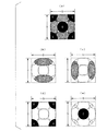
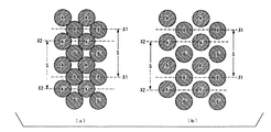
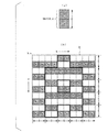
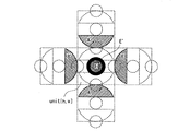
画線Aと画線A’、画線Bと画線B’に関し、縦横の長さがSである四角形内において、縦軸方向に円形の画線Aと画線A’とを長さSの約半分の長さをそれぞれ持って配置し、横軸方向に円形の画線Bと画線B’とを長さSの約半分の長さをそれぞれ持って配置している。更に、四角形の四隅に画線Cの中心が来るように、それぞれ4分の1ずつを配置している。 Regarding the image line A and the image line A ′, and the image line B and the image line B ′, in the quadrangle whose vertical and horizontal lengths are S, the circular image line A and the image line A ′ are length S in the vertical axis direction. The circular image line B and the image line B ′ are disposed so as to have approximately half the length S in the horizontal axis direction. Further, a quarter of each is arranged so that the center of the drawing line C comes to the four corners of the rectangle.
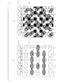
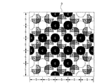
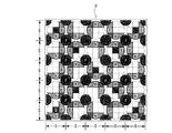
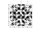
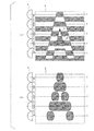
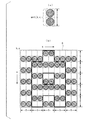
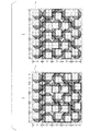
このような構成を有する画線を印刷物上にマトリクス状に隙間なく、連続的かつ規則的に配置すると図6のようである。この図6は、印刷物に印刷された印刷模様3を構成するマトリクス状に配置された複数の画線を、第1の不可視画像、第2の不可視画像及び第1の可視画像のそれぞれの構成が解るように簡易的に示した模式図である。印刷模様3において、画線Aの総画線面積と画線A’の総画線面積とが等しく、それぞれ対になっているもの同士がネガポジの関係にあることによって、第1の不可視画像が通常の目視では不可視の状態になっている。同様に、画線Bと画線B’により構成される第2の不可視画像が不可視の状態になっている。
When the image lines having such a configuration are arranged continuously and regularly on the printed matter in a matrix without any gaps, it is as shown in FIG. FIG. 6 shows a plurality of image lines arranged in a matrix that constitutes the printed
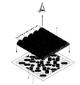
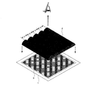
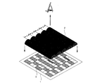
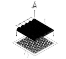
この状態で、図7に示されたように、例えば、レンチキュラーレンズから成る判別具2を印刷物1上の印刷模様3に重ね合わせ、正面から目視で観察することによって、印刷模様3に施されている不可視画像を可視画像として発現させることができる。なお、本実施の形態1では、長さSが340μmで、印刷模様3がオフセット印刷によりコート紙に印刷されている。しかし、長さS、印刷物の基材、印刷方法、印刷材料、印刷装置等について何ら限定するものでない。
In this state, as shown in FIG. 7, for example, the discriminating
通常の目視では、可視画像が視認されるが、不可視画像は、視認されない。判別具を印刷模様上の所定の位置に重ね合わせると、それまで視認されていた可視画像が全く確認できなくなり、逆に不可視画像が視認されるようになる。このような本実施の形態1による印刷物における画像のスイッチ効果の原理について、以下に説明する。 In normal visual observation, a visible image is visually recognized, but an invisible image is not visually recognized. When the discriminating tool is overlaid at a predetermined position on the printed pattern, the visible image that has been viewed until then cannot be confirmed at all, and the invisible image can be viewed. The principle of the image switching effect in the printed matter according to the first embodiment will be described below.
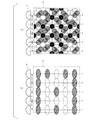
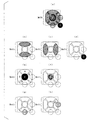
可視画像が視認され不可視画像が視認されていないとき、その可視画像を構成しているのは画線Cであり、その背景一面を構成しているのが不可視画像を構成する画線A又はA’及び画線B又はB’である。画線A及び画線A’、画線B及びB’はそれぞれネガポジの関係にあるとともに面積が同一であるため、画像(模様)として確認されることはない。 When the visible image is visually recognized and the invisible image is not visually recognized, it is the image line C that constitutes the visible image, and the image line A or A that constitutes the background image constitutes the entire surface of the background. 'And the image line B or B'. The image line A, the image line A ′, and the image lines B and B ′ have a negative-positive relationship and the same area, and thus are not confirmed as an image (pattern).
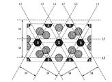
印刷物上の所定の位置に、判別具であるレンチキュラーレンズにおける各レンズの中心線が画線Aの中心、すなわち図5における線L1に一致するように載置する。この場合、画線Aが拡大された状態となるため、画線Aにより構成されている画像(模様)が確認できることとなる。その際、可視画像を構成していた画線C及び不可視画像を構成している画線B及びB’は、拡大されている画線Aよりも面積が相対的に小さくなる。更に、画線B及びB’は、相互にネガポジの関係にある。これにより、画像としてではなく、一様な背景としてしか視認されないため、実際上には画像がスイッチすることとなる。画線A’が拡大されるように縦軸方向に沿って判別具を移動させた場合、画線Aにより視認された第1の不可視画像のネガポジが反転して視認される。また、判別具を90度回転させ、レンチキュラーレンズの各レンズの中心線が図5における線L3と一致するようにすることで、画線Bが拡大されるように判別具を載置した場合、更にこの状態から横軸方向に沿って画線B’が拡大されるように載置した場合にも、同様の原理で第2の不可視画像のネガポジが反転して視認される。 The lens is placed at a predetermined position on the printed material so that the center line of each lens in the lenticular lens as a discriminator coincides with the center of the image line A, that is, the line L1 in FIG. In this case, since the image line A is in an enlarged state, an image (pattern) constituted by the image line A can be confirmed. At this time, the area of the image line C constituting the visible image and the image lines B and B ′ constituting the invisible image are relatively smaller than those of the enlarged image line A. Further, the image lines B and B 'are in a negative-positive relationship with each other. As a result, since the image is viewed only as a uniform background, not as an image, the image is actually switched. When the discriminator is moved along the vertical axis direction so that the image line A ′ is enlarged, the negative / positive of the first invisible image visually recognized by the image line A is viewed in an inverted manner. Also, when the discriminator is placed so that the image line B is enlarged by rotating the discriminator 90 degrees so that the center line of each lens of the lenticular lens matches the line L3 in FIG. Further, when the image B is placed so that the image line B ′ is enlarged along the horizontal axis direction from this state, the negative / positive of the second invisible image is reversed and visually recognized by the same principle.
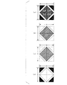
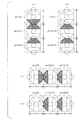
印刷模様3に、所定の角度、より具体的には図5における線L1と各レンズの中心線とが一致するように、レンチキュラーレンズから成る判別具2を印刷物1上の印刷模様3に重ね合わせ、正面から目視で観察した状態を図8に示す。レンチキュラーレンズの中心線7が図5における線L1と一致するように図8(a)に示された位置にあるとき、中心線7に位置するのは、画線Aとなっている。レンチキュラーレンズの特性によって中心線7に位置する画線Aが膨張して見えるため、目視では図8(b)に示されたような図形の可視画像が発現する。また、レンチキュラーレンズの中心線7が図5における線L2と一致し、図9(a)に示された位置にあるとき、中心線7に位置するのは、画線A’となっている。レンチキュラーレンズの特性によって中心線7に位置する画線A’が膨張して見えるため、目視では図9(b)に示されたような図形の可視画像が発現する。ここで、画線Aと画線A’とはネガポジの関係にある。よって、上述の図3(a)又は図3(b)に示されたような第1の不可視画像がネガポジ状のどちらかに見える可視画像となって発現する。
A
図5における線L2とレンチキュラーレンズの各レンズの中心線が図5における線L3と一致するように、印刷模様3に90度の角度を持って判別具2を印刷物1上の印刷模様3に重ね合わせ、正面から目視で観察した状態を図10に示す。この場合、レンチキュラーレンズの中心線7が図10(a)に示された位置にあり、中心線7に位置するのは画線Bとなっている。レンチキュラーレンズの特性によって中心線7に位置する画線Bが膨張して見えるため、目視では図10(b)に示されたような図形の可視画像が発現する。また、レンチキュラーレンズの中心線7が図5における線L4と一致し、図11(a)に示された位置にあるとき、中心線7に位置するのは、画線B’となっている。レンチキュラーレンズの特性によって中心線7に位置する画線B’が膨張して見えるため、目視では図11(b)に示されたような図形の可視画像が発現する。つまり、前述の図4(a)又は図4(b)に示されたような第2の不可視画像が、ネガポジ状のどちらかに見える可視画像となって発現するものである。
The
なお、判別具を用いた第1、第2の不可視画像を判別する際において、画線Cにより形成される可視画像は、ほとんど見えなく、あるいは見え難くなる。このため、第1の不可視画像及び第2の不可視画像が可視画像として発現したときに、これらの視認性を阻害することはない。 When discriminating the first and second invisible images using the discriminator, the visible image formed by the image line C is hardly visible or difficult to see. For this reason, when a 1st invisible image and a 2nd invisible image are expressed as a visible image, these visibility is not inhibited.
ここで判別具2は、レンチキュラーレンズにかかわらず、例えば、万線フィルタであっても同様の効果が得られる。この万線フィルタの場合は、フィルタ上の万線に該当する部分が可視画像を構成する画線を隠蔽することで、不可視画像を構成する画線のみが確認できることとなるが、可視画像を完全には隠蔽することができずに若干視認されてしまうことがある。ただし、これによって本発明の効果を損なうことはないため、簡易的に判別を行うには、万線フィルタを用いても充分である。なお、後述する実施の形態2及び3についても同様である。
Here, regardless of the lenticular lens, the
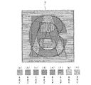
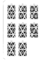
ところで、本実施の形態1における印刷物1の一画線の画線A、A’、B、B’は円形形状を有している。しかしこのような形状には限定されず、例えば、図29に示された画線のように四角形等の多角形形状であっても良い。一画線が、少なくとも三つ以上の画線要素を有し、画線Aと画線A’とが対を成してネガポジの関係にあり、かつ、面積が同一であって第1の不可視画像を構成し、画線Bと画線B’とが対を成してネガポジの関係にあり、かつ、面積が同一であって第2の不可視画像を構成し、更に画線Cが第1の可視画像(デザイン:模様)として視認されるものであれば、画線の形状は何ら限定するものではない。
By the way, the image lines A, A ′, B, and B ′ of the one line of the printed
本実施の形態1によれば、画線Cを用いて自由度が高く意匠性を有する鮮明な可視画像を、不可視画像の発現時における視認性を阻害することなく形成することができるため、有価証券等の印刷物においても有用である。また、印刷物上に単一の判別具を重ね合わせることによって、画線A及びA’、画線B及びB’で形成される不可視画像を容易に、かつ、鮮明に発現させることが可能である。更に、本発明における印刷物を構成する各画線を同一色とした単色印刷のみでも十分な偽造防止効果が得られる上に、製版及び印刷方法等について何ら限定しないため、コストを低減させることができる。 According to the first embodiment, it is possible to form a clear visible image having a high degree of freedom and design using the image line C without impairing the visibility when the invisible image is expressed. It is also useful for printed materials such as securities. Also, by overlaying a single discriminator on the printed material, it is possible to easily and clearly express invisible images formed by the image lines A and A ′ and the image lines B and B ′. . Furthermore, a sufficient anti-counterfeit effect can be obtained only by monochromatic printing in which the image lines constituting the printed matter in the present invention have the same color, and the plate making and printing methods are not limited at all, and thus the cost can be reduced. .
(2)実施の形態2
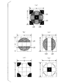
図12に、本発明の実施の形態2における印刷物に対する印刷模様の一画線の構成要素を拡大して示す。図12(a)に示されたように、印刷模様3は、少なくとも三つ以上の画線要素で構成されている。図12(b)に示されたように、画線Aと画線A’とは、対を成し、ネガポジの関係にあり、かつ、面積が同一であって、第1の不可視画像を構成する。画線Aと画線A’とが四角形内において中心から上下に対称に配置されている。(2)
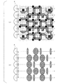
FIG. 12 shows an enlarged view of the components of one stroke of the printed pattern for the printed matter in the second embodiment of the present invention. As shown in FIG. 12A, the printed
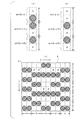
画線Bと画線B’とは、図12(c)に示されたように対を成してネガポジの関係にあり、かつ、面積が同一であって第2の不可視画像を構成する。画線Bと画線B’とが四角形内において中心から左右対称に配置されている。更に、画線Cは、図12(d)に示されたように、四角形の四隅に画線Cの中心が位置し4分の1ずつに分割して配置されている。この画線Cが第1可視画像(デザイン:模様)を構成する。 The image line B and the image line B 'are paired as shown in FIG. 12C and have a negative-positive relationship, and have the same area and constitute a second invisible image. The image line B and the image line B 'are arranged symmetrically from the center in the rectangle. Furthermore, as shown in FIG. 12 (d), the image line C is divided into quarters with the center of the image line C positioned at the four corners of the quadrangle. This drawing line C constitutes a first visible image (design: pattern).
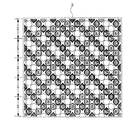
図13に、画線A及びA’により第1の不可視画像が形成され、画線B及びB’により第2の不可視画像が形成され、画線Cにより第1の可視画像が形成されることを簡易的に模式図として示す。 In FIG. 13, the first invisible image is formed by the lines A and A ′, the second invisible image is formed by the lines B and B ′, and the first visible image is formed by the line C. Is simply shown as a schematic diagram.
通常の目視状態では、画線Aの総画線面積と画線A’の総画線面積とが等しいことによって、第1の不可視画像が不可視の状態になっている。また、画線Bの総画線面積と画線B’の総画線面積とが等しいことによって、第2の不可視画像が不可視の状態になっている。 In a normal visual state, the first invisible image is invisible because the total area of the image A is equal to the total area of the image A ′. Further, since the total image area of the image line B is equal to the total image area of the image line B ′, the second invisible image is in an invisible state.
これに対し、図14に示されるように、判別具2を印刷物1上の印刷模様3の所定位置に重ね合わせ、正面から目視で観察することによって、第1又は第2の不可視画像を可視画像として発現させることができる。なお、本実施の形態2でも、前述の実施の形態1と同様に、長さSを340μmとし、印刷模様3は、オフセット印刷によってコート紙に印刷したが、長さS、印刷方法、印刷材料及び印刷装置について何ら限定するものではない。
On the other hand, as shown in FIG. 14, the discriminating
印刷模様3に対して、レンチキュラーレンズの各レンズの中心線7が図12における線L11と一致するように、レンチキュラーレンズから成る判別具2を印刷物1上の印刷模様3に重ね合わせ、正面から目視で観察した状態を図15に示す。この場合、レンチキュラーレンズの中心線7が図15(a)に示された位置にあり、中心線7上に位置するのは画線A、B及びB’となっている。レンチキュラーレンズの特性により、中心線7に位置する画線A、B及びB’のうち、相対的に面積の大きい画線Aがより膨張して大きく見える。このため、目視では図15(b)に示されるような面積の大きい画線Aと相対的に小さい画線B、B’とで形成される図形の可視画像が発現する。ここで、画線BとB’とは、ネガポジの関係にあり、かつ、面積が同一であるため、結果的に画線Aにより形成される図形が可視画像として視認されることになる。
The
レンチキュラーレンズの中心線7が図12における線L12と一致し、図16(a)に示された位置にあるとき、中心線7に位置するのは画線A’、B及びB’となっている。レンチキュラーレンズの特性によって、中心線7に位置する画線A’、B及びB’が膨張して見える。特に面積の大きいA’がより膨張して見えるため、目視では図16(b)に示されたような図形の可視画像が発現する。画線BとB’とがネガポジの関係にあり、かつ、面積が同一のゆえ、画線A’により形成される図形が可視画像として視認される。つまり、図3(a)又は図3(b)に示されたような第1の不可視画像がネガポジ状のどちらかに見える可視画像となって発現する。
When the
印刷模様3に対し、レンチキュラーレンズの各レンズの中心線7が図12における線L13に一致するように、レンチキュラーレンズから成る判別具2を印刷物1上の印刷模様3に重ね合わせ、正面から目視で観察した状態を図17に示す。この場合、レンチキュラーレンズの中心線7が図17(a)に示された位置にあり、中心線7に位置するのは画線B、A及びA’となっている。レンチキュラーレンズの特性によって中心線7に位置する画線Bが、より膨張して見え、また、画線A及びA’は、ネガポジの関係にあることから、目視では図17(b)に示されたような図形の可視画像が発現する。また、レンチキュラーレンズの中心線7が図12の線L14に一致し、図18(a)に示された位置にあるとき、中心線7に位置するのは、画線B’、A及びA’となっている。レンチキュラーレンズの特性により、また、画線A及びA’がネガポジの関係にあることから、中心線7に位置する画線B’が膨張して見えて、目視では図18(b)に示されたような図形の可視画像が発現する。つまり、前述の図4(a)又は図4(b)に示された第2の不可視画像がネガポジ状のどちらかに見える可視画像となって発現するものである。
The
上記実施の形態1において述べたように、判別具2は、レンチキュラーレンズに限らず、例えば、万線フィルタであっても同様の効果が得られる。判別具2を用いた観察時において、画線Cは極めて視認が困難になるため、第1の不可視画像並びに第2の不可視画像が可視画像として発現したときの視認性を阻害することはない。
As described in the first embodiment, the
本実施の形態2における印刷物1の印刷模様3の画線構成は、図12に示されたような円形の画線形状に限らず、図30(a)に示されたような四角形等の多角形の画線形状であっても良い。すなわち、印刷模様3は、少なくとも三つ以上の画線要素で構成し、それぞれの画線要素を詳しく説明すると、画線Aと画線A’は、図30(b)に示されたようにペア構成で第1不可視画像が施され、画線Aと画線A’は四角形内において中心から上下対称に配置し、また、画線Bと画線B’は図30(c)に示されたようにペア構成で第2不可視画像が施され、画線Bと画線B’が四角形内において中心から左右対称に配置し、更に、画線Cは図30(d)に示されたように第1可視画像(デザイン:模様)として視認されるものであれば、本実施の形態2の画線形状を何ら限定するものではない。また、画線Aと画線A’とで画線面積率が一致していれば、個々の形を限定するものではない。また更に、画線Bと画線B’とで画線面積率が一致していれば、個々の形を限定するものではない。
The image line configuration of the printed
本実施の形態2によれば、画線Cを用いて自由度が高く意匠性を有する鮮明な可視画像を、不可視画像の発現時における視認性を阻害することなく形成することができるため、有価証券等の印刷物においても有用である。また、印刷物上に単一の判別具を重ね合わせることによって、画線A及びA’、画線B及びB’で形成される不可視画像を容易に、かつ、鮮明に発現させることが可能である。更に、本発明における印刷物を構成する各画線を同一色とした単色印刷のみでも十分な偽造防止効果が得られる上に、製版及び印刷方法等について何ら限定しないため、コストを低減させることができる。 According to the second embodiment, it is possible to form a clear visible image having a high degree of freedom and design using the image line C without impairing the visibility when the invisible image is expressed. It is also useful for printed materials such as securities. Also, by overlaying a single discriminator on the printed material, it is possible to easily and clearly express invisible images formed by the image lines A and A ′ and the image lines B and B ′. . Furthermore, a sufficient anti-counterfeit effect can be obtained only by monochromatic printing in which the image lines constituting the printed matter in the present invention have the same color, and the plate making and printing methods are not limited at all, and thus the cost can be reduced. .
(3)実施の形態3
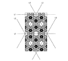
上記実施の形態1及び実施の形態2において、印刷物1の印刷模様3を通常の条件下で目視により観察すると、図2に示されたような図形及び文字から成る模様4が視認される。これに対し本実施の形態3においては、図19に示されたように、模様4に加えて更に任意の図形及び文字から成る模様8を施すことができる。例えば、図19に示された模様4と模様8とは重畳するような配置となっており、これに限らず様々なデザイン表現を施すことができる。(3)
In the first embodiment and the second embodiment, when the printed
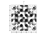
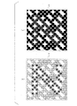
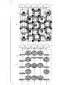
図20に、実施の形態3における印刷物に形成された印刷模様の一画線の構成要素を拡大して示す。図20(a)に示されるように、印刷模様3は、少なくとも四つ以上の画線要素で構成されている。図20(b)に示されるように、画線Aと画線A’とは、対を成して第1の不可視画像を形成し、画線Aと画線A’とがそれぞれ四角形内において中心から上下対称に配置されている。図20(c)に示されたように画線Bと画線B’とが対を成して第2の不可視画像を形成し、画線Bと画線B’とは、それぞれ四角形内において中心から左右対称に配置されている。図20(d)に示されたように画線Cは、第1可視画像(デザイン:模様)を形成し、図19に示されたような任意の図形及び文字から成る模様4を構成する画線となり、四角形の四隅に画線Cの中心がくるように4分の1ずつが配置されている。更に、画線Dは図20(e)に示されたように、第2可視画像(デザイン:模様)を形成し、図19に示されたような任意の図形及び文字から成る模様8を構成する画線となり、四角形の中心に画線Dの中心が一致するように配置されている。
FIG. 20 shows an enlargement of the components of one stroke of the printed pattern formed on the printed matter in the third embodiment. As shown in FIG. 20A, the printed
図21に、印刷模様3を構成する各画線の位置関係を簡易的に示す。ネガポジの関係にある画線Aの総画線面積と画線A’の総画線面積とが等しいことによって、第1の不可視画像が不可視の状態になっている。同様に、ネガポジの関係にある画線Bと画線B’との総画線面積が等しいことによって、第2の不可視画像が不可視の状態になっている。例えば、図22に示されたように、判別具2を印刷物1上の印刷模様3に重ね合わせ、正面から目視で観察することによって、印刷模様3に施されている不可視画像を可視画像として発現させることができる。なお、本実施の形態3では、前述の実施の形態1及び2と同様に、長さSが340μm、印刷模様3をオフセット印刷によりコート紙に印刷したが、長さS、印刷方法、印刷材料及び印刷装置については何ら限定するものではない。
FIG. 21 simply shows the positional relationship between the image lines constituting the printed
印刷模様3に対して、レンチキュラーレンズの各レンズの中心線7が図20における線L21に一致するように、レンチキュラーレンズから成る判別具2を印刷物1上の印刷模様3に重ね合わせ、正面から目視で観察した状態を図23に示す。この場合、レンチキュラーレンズの中心線7が図23(a)に示された位置にあり、中心線7上に位置するのは画線Aと、画線B及びB’となっている。レンチキュラーレンズの特性によって、中心線7に位置する画線A、B及びB’が膨張して見えるため、目視では図23(b)に示されたような図形の可視画像が発現する。ここで、画線B及びB’は、ネガポジの関係にあり、かつ、面積が同一であるため、これらにより形成される画像は視認されない。このため、画線Aにより形成される第1の不可視画像のみが視認される。
The
レンチキュラーレンズの中心線7が図20における線L22に一致し、図24(a)に示された位置にあるとき、中心線7に位置するのは、画線A’、B及びB’となっている。レンチキュラーレンズの特性によって中心線7に位置する画線A’、B及びB’が膨張して見えるため、目視では図24(b)に示されたような図形の可視画像が発現する。この場合も、画線B及びB’により形成される画像は視認されず、画線A’により形成され、画線Aによるものとはネガポジが反転した関係にある第1の不可視画像が視認される。すなわち、図3(a)又は図3(b)に示されたような第1の不可視画像がネガポジのいずれかの状態で可視画像となって発現する。
When the
印刷物1の模様3に対し、レンチキュラーレンズにおける各レンズの中心線7が図20における線L23と一致するように、レンチキュラーレンズから成る判別具2を印刷物1上の印刷模様3に重ね合わせ、正面から目視で観察した状態を図25に示す。この場合、レンチキュラーレンズの中心線7が図25(a)に示された位置にあり、中心線7に位置するのは画線B、A及びA’となっている。レンチキュラーレンズの特性によって中心線7に位置する画線B、A及びA’が膨張して見えるため、目視では図25(b)に示されたような図形の可視画像が発現する。しかし、画線A及びA’は、ネガポジの関係にあり、かつ面積が同一である。このため、画線Bにより形成される第2の不可視画像が視認される。
The
レンチキュラーレンズの中心線7が図20における線L24と一致して図26(a)に示された位置にあるとき、中心線7に位置するのは、画線B’、A及びA’となっている。レンチキュラーレンズの特性によって中心線7に位置する画線B’、A及びA’が膨張して見えるため、目視では図26(b)に示されたような図形の可視画像が発現する。この場合も同様の理由で、画線B’により形成される第2の不可視画像が視認される。
When the
つまり、前述した図4(a)又は図4(b)に示されたような第2の不可視画像がネガポジ状のいずれかにより可視画像となって発現する。 That is, the second invisible image as shown in FIG. 4 (a) or FIG. 4 (b) described above appears as a visible image by either negative-positive shape.
本実施の形態3では、判別具としてレンチキュラーレンズを用いているが、前述した実施の形態1及び2の場合と同様に、例えば、万線フィルタであっても同様の効果が得られる。レンチキュラーレンズでの観察時において、画線Cはほとんど視認されないため、第1の不可視画像及び第2の不可視画像が可視画像として発現したときの視認性を阻害することはない。 In the third embodiment, a lenticular lens is used as a discriminator. However, as in the first and second embodiments described above, for example, the same effect can be obtained even with a line filter. At the time of observation with the lenticular lens, the image line C is hardly visually recognized, so that the visibility when the first invisible image and the second invisible image appear as visible images is not hindered.
本実施の形態3における印刷物1の印刷模様3の画線は、図20に示されたような円形の形状に限らず、図31(a)に示されたような楕円形であっても良い。印刷模様3は、少なくとも四つ以上の画線要素を備える。画線Aと画線A’は、図31(b)に示されたように対を成して第1の不可視画像を構成し、画線Aと画線A’とが四角形内において中心に対して上下に対称に配置される。画線Bと画線B’は、図31(c)に示されたように対を成して第2の不可視画像を構成し、画線Bと画線B’とが四角形内において中心に対して左右に対称に配置される。画線Cは、図31(d)に示されたように第1の可視画像(デザイン:模様)として視認され、画線Dは、図31(e)に示されたように第2可視画像(デザイン:模様)として視認される。画線Aと画線A’とは面積が同一であり、また、画線Bと画線B’も面積が同一である。このような構成を備えるものであれば、各々の画線の形状については限定するものではない。
The image line of the printed
本実施の形態3によれば、画線C及びDを用いて自由度が高く意匠性を有する鮮明な可視画像を、不可視画像の発現時における視認性を阻害することなく形成することができるため、有価証券等の印刷物においても有用である。また、印刷物上に単一の判別具を重ね合わせることによって、画線A及びA’、画線B及びB’で形成される不可視画像を容易、かつ、鮮明に発現させることが可能である。更に、本発明における印刷物を構成する各画線を同一色とした単色印刷のみでも十分な偽造防止効果が得られる上に、製版及び印刷方法等について何ら限定しないため、コストを低減させることができる。 According to the third embodiment, it is possible to form a clear visible image having a high degree of freedom and design using the lines C and D without impairing the visibility when the invisible image is expressed. It is also useful for printed materials such as securities. Further, by overlaying a single discriminating tool on the printed material, it is possible to easily and clearly express an invisible image formed by the image lines A and A ′ and the image lines B and B ′. Furthermore, a sufficient anti-counterfeit effect can be obtained only by monochromatic printing in which the image lines constituting the printed matter in the present invention have the same color, and the plate making and printing methods are not limited at all, and thus the cost can be reduced. .
(4)実施の形態4
実施の形態1乃至3では、レンチキュラーレンズ等の判別具を用いて視認することができる少なくとも一種類以上の不可視画像を設けた偽造防止用印刷物を説明したが、実施の形態4による偽造防止用印刷物では、レンチキュラーレンズ等の判別具を用いて視認することができる少なくとも一種類以上の不可視画像に加え、判別具を用いずとも視認できる不可視画像を施した例について説明する。(4)
In the first to third embodiments, the forgery prevention printed matter provided with at least one invisible image that can be visually recognized using a discriminator such as a lenticular lens has been described. However, the forgery prevention printed matter according to the fourth embodiment is described. Now, an example will be described in which an invisible image that can be visually recognized without using a discriminator is provided in addition to at least one invisible image that can be viewed using a discriminator such as a lenticular lens.
図32は、本実施の形態4における画線構成を示したものである。基本的な画線構成は、図21に示された画線の配置と同様である。図32に示される画線A、A’、B、B’、C、及びDは、光輝性材料を含むインキ、例えば金属光沢を有する銀インキ等で印刷された印刷模様3を構成している。そして、印刷模様3における画線C上に、任意の有色、例えば薄紫色インキから成る画線Fを印刷している。この画線Fは、画線Cにて構成される第1可視画像並びに画線Dにて構成される第2可視画像とは別に、印刷物の観察条件によって現出する画像を構成するものである。本実施の形態4では、画線Fの配置にて「N」の文字を構成している。また、本実施の形態4における画線Cの画線面積は、画線Fと同じ又は画線Fよりも大きい。なお、本実施の形態4における光輝性材料並びに有色インキは何ら限定するものではい。
FIG. 32 shows an image line configuration in the fourth embodiment. The basic image line configuration is the same as the image line arrangement shown in FIG. The image lines A, A ′, B, B ′, C, and D shown in FIG. 32 constitute a printed
図33は、本実施の形態4における印刷模様3が印刷された印刷物1において、印刷物1を拡散光領域と正反射光領域とで観察したときのそれぞれの照明光源9と視点10と印刷物1の三つの位置関係を図示したものである。照明光源9と視点10と印刷物1が図33(a)の位置関係にあるとき、拡散光領域で観察したことになり、照明光源9と視点10と印刷物1が図33(b)の位置関係にあるとき、正反射光領域で観察したことになる。
FIG. 33 shows the
図33(a)で示されたように、拡散光領域で印刷物1を目視で観察した場合、図34(a)で示されたように、印刷模様3上に施された薄紫色の画線Fが視認され難くなり、主として銀インキから成る画線C及びDで構成された二種類の可視画像が視認できる状態となる。一方、図33(b)に示されたように、正反射光領域で印刷物1を目視で観察した場合、図34(b)で示されたように、銀インキから成る画線A、A’、B、B’、C及びDは、正反射光がもたらす光輝性の作用によって明度が高まり、光輝性の作用を有さない薄紫色インキから成る画線Fのみが強調されて視認される。したがって、画線Fの配置で構成した「N」の文字が観察される。
As shown in FIG. 33 (a), when the printed
(5)実施の形態5
本実施の形態5は実施の形態4と同様に、レンチキュラーレンズ等の判別具を用いて視認することができる少なくとも一種類以上の不可視画像に加え、判別具を用いずとも視認できる不可視画像を施した例について説明する。(5)
In the fifth embodiment, similarly to the fourth embodiment, in addition to at least one type of invisible image that can be visually recognized using a discriminator such as a lenticular lens, an invisible image that can be viewed without using the discriminator is applied. An example will be described.
図35は、本実施の形態5における画線構成を示したものである。基本的な画線構成は、図21に示された画線の配置と同様である。図35に示される画線A、A’、B、B’、C及びDは、光輝性材料を含むインキ、例えば金属光沢を有する銀インキ等で印刷された印刷模様3を構成している。そして、印刷模様3上に無色透明材料、例えば透明ニス等から成る模様Gを印刷している。この模様Gは、画線A、A’、B、B’、C及びDの配置と特別な位置関係は無い。本実施の形態5では、模様Gの配置にて「N」の文字を構成している。なお、本実施の形態5における光輝性材料及び無色透明材料は何ら限定するものではい。
FIG. 35 shows an image line configuration in the fifth embodiment. The basic image line configuration is the same as the image line arrangement shown in FIG. The image lines A, A ′, B, B ′, C and D shown in FIG. 35 constitute a printed
図33は、本実施の形態5における印刷模様3が印刷された印刷物1において、印刷物1を拡散光領域と正反射光領域とで観察したときのそれぞれの照明光源9と視点10と印刷物1の三つの位置関係を図示したものである。照明光源9と視点10と印刷物1が図33(a)の位置関係にあるとき、拡散光領域で観察したことになり、照明光源9と視点10と印刷物1が図33(b)の位置関係にあるとき、正反射光領域で観察したことになる。
FIG. 33 shows the
図33(a)で示されたように、拡散光領域で印刷物1を目視で観察した場合、図36(a)で示されたように、印刷模様3上に施された無色透明材料から成る模様Gは完全に透過しているので、主として銀インキから成る画線C及びDで構成された二種類の可視画像が視認できる状態となる。一方、図33(b)に示されたように、正反射光領域で印刷物1を目視で観察した場合、図36(b)で示されたように、銀インキから成る画線A、A’、B、B’、C及びDは、正反射光がもたらす光輝性の作用によって明度が高まり、無色透明材料から成る模様Gの部分については、画線A、A’、B、B’、C及びDの光輝性の作用が抑制される。これにより、模様Gのみが光輝性の違いで強調されて視認される。したがって、模様Gの配置で構成した「N」の文字が観察される。
As shown in FIG. 33 (a), when the printed
以下に説明する実施の形態6〜8では、印刷物1上に判別具2を所定の角度(これを0度とする。)を持って重ね合わせると、図37(a)に示されたような第1の不可視画像5が可視画像となって発現し、その位置から判別具2をわずかに縦軸方向にずらすと、図37(b)に示されたような第2の不可視画像6が可視画像となって出現する。また、更に判別具2を縦軸方向にわずかにずらして重ね合わせると、図38(a)に示されたような第1の不可視画像5がポジ状態で出現し、その位置から判別具2をわずかに縦軸方向にずらすと、図38(b)に示されたような第2の不可視画像6がポジ状態となって出現する。図37(a)又は図38(a)及び図37(b)又は図38(b)に示されるようにネガポジ状のどちらかに見えるのは、判別具2と印刷物1との間の相対的な位置によって生ずるものであり、本発明の効果の範囲内である。
In
(6)実施の形態6
以下、本発明の実施の形態6による偽造防止用印刷物について説明する。(6)
The forgery prevention printed matter according to
図39は、実施の形態6の偽造防止用印刷物1の不可視画像を構成する画線である。図39(a)に示すように、画線Aと画線A’は、仮想の中心線X1に対して対向しており、相互にネガポジの関係にある。このネガポジの関係とは、例えば、一方が黒(オン)のときは他方は白(オフ)、一方が有着色のときは他方は無着色であり、双方共に黒又は白であることがないということである。そして、この画線Aと画線A’とは面積が同一であり、これらの画線により第1の画線要素8を構成している。
FIG. 39 is an image line constituting an invisible image of the forgery prevention printed
また、図39(b)については、図39(a)と同じように、画線Bと画線B’とが仮想の中心線X2に対して対向しており、相互にネガポジの関係にある。この画線Bと画線B’とは面積が同一であり、これらの画線により第2の画線要素9を構成している。
In FIG. 39 (b), as in FIG. 39 (a), the image line B and the image line B ′ are opposed to the virtual center line X2, and are in a negative-positive relationship with each other. . The image line B and the image line B 'have the same area, and the second
図40は、前述した各画線要素を一定の方向Yに複数配置したものである。図40(a)は、第1の画線要素8を一定の方向Yに複数配置した第1の不可視画像要素10であり、図40(b)は、第2の画線要素9を第1の画線要素8が配置されている方向と同じ一定の方向Yに複数配置した第2の不可視画像要素11である。第1の不可視画像要素10を構成している各画線要素の中心線X1同士の距離(ピッチ)Sは一定であり、また、第2の不可視画像要素11を構成している各画線要素の中心線X2同士の距離(ピッチ)Sも一定であり、第1の不可視画像要素10におけるピッチSと第2の不可視画像要素11におけるピッチSは同じである。なお、このピッチSについては、可視状態におけるデザインを考慮して1mm以下となる。
FIG. 40 shows a plurality of the above-described image line elements arranged in a certain direction Y. FIG. 40A shows the first
図41は、前述した第1の不可視画像要素10と第2の不可視画像要素11が規則的に複数配列されている図である。この規則的な配列とは、第1の不可視画像要素10を構成している第1の画線要素8の中心線X1の位置に、第2の不可視画像要素11を構成している第2の画線要素9の各画線B及びB’の中心がくるように配置されることであり、第1の不可視画像要素10のピッチSと第2の不可視画像要素11のピッチSは同じであるから、第1の不可視画像要素10に対して、第2の不可視画像要素11を1/4ピッチずらして配列していることとなる。なお、図41(a)は、第1の不可視画像要素10と第2の不可視画像要素11とが接して配列されている図であり、図41(b)は、第1の不可視画像要素10と第2の不可視画像要素11とが接していないように配列されている図である。可視状態におけるデザインを考慮すると、図41(a)のように接している方が好ましい。
FIG. 41 is a diagram in which a plurality of the first
このような不可視画像要素10及び不可視画像要素11を、基材上にマトリクス状に透き間なく、連続的に、かつ、規則的に配置すると図42のようになる。この図42は、印刷物に印刷された印刷模様3を構成するマトリクス状に配置された複数の画線を、第1の不可視画像、第2の不可視画像及び可視画像のそれぞれの構成が分るように簡易的に示した模式図であり、図43は、図42において丸で囲んだ一部分の拡大図を示す。なお、この図において、点線囲いの空白画線は、前述のとおり、各画線要素は二つの画線が対となって配置されており、ネガポジの関係を有しているため、一方が黒(オン)のときには、他方は白(オフ)の状態となっているものである。
When such
また、図42における画線Cについては、印刷物において可視画像(デザイン:模様)を構成するものであり、通常の視認状態において肉眼で視認される任意の図形及び文字等から成る模様を示す。ここで可視画像とは、通常の可視光の下で目視により視認され得る画像であり、不可視画像とは、通常の可視光の下で目視により視認され得ないか、又は極めて視認され難い画像のことである。この画線Cは、図42に示されたように、不可視画像を構成する画線A、A’、B及びB’の一部の画線と重複する位置に配置されて可視画像を構成する。また、画線Cから構成される可視画像(デザイン:模様)が、画線A、A’、B及びB’を完全に隠さないように交互に配置するなどといった、可視画像を構成する画線Cの数を少なくとも全体の画線数の半分程度に抑えることが好ましい。 Further, the image line C in FIG. 42 constitutes a visible image (design: pattern) in the printed matter, and shows a pattern made up of arbitrary figures, characters, and the like visually recognized with the naked eye in a normal viewing state. Here, the visible image is an image that can be visually recognized under normal visible light, and the invisible image is an image that cannot be visually observed under normal visible light or is extremely difficult to be visually recognized. That is. As shown in FIG. 42, the image line C is arranged at a position overlapping with some image lines of the image lines A, A ′, B, and B ′ forming the invisible image to form the visible image. . In addition, a visible image (design: pattern) composed of the image line C is alternately arranged so as not to completely hide the image lines A, A ′, B, and B ′. It is preferable to suppress the number of C to at least about half of the total number of lines.
画線Cと不可視画像を構成する各画線A、A’、B及びB’との位置関係は、前述のとおり各画線の一部の画線と重複する位置に配置されるものであるが、可視画像を明確に視認させるために、その大きさについては、図44(a)に示すように同じ又は図44(b)に示すように、それ以上、いわゆる「画線Cの面積≧画線A、A’、B及びB’の面積」の関係となり、好ましくはすべての画線の大きさが同じとなることである。本実施の形態6においては、すべての画線の大きさを同じに構成している。 As described above, the positional relationship between the image line C and each image line A, A ′, B, and B ′ that configure the invisible image is arranged at a position that overlaps a part of the image lines. However, in order to make the visible image clearly visible, the size thereof is the same as shown in FIG. 44A or more so-called “the area of the image line C ≧ It is a relationship of “areas of image lines A, A ′, B and B ′”, and preferably all image lines have the same size. In the sixth embodiment, all the image lines are configured to have the same size.
また、画線Cを画線A、A’、B及びB’の一部の画線に重複する位置に配置することについては、例えば、本来画線Aを配置する箇所に画線Aを配置せずに、画線Cを配置しても良く、また先に画線Aを配置した上に、重ね刷りにより画線Cを配置してもよい。 In addition, regarding the arrangement of the image line C at a position overlapping with some image lines of the image lines A, A ′, B, and B ′, for example, the image line A is arranged at a position where the image line A is originally arranged. However, the image line C may be arranged, or the image line C may be arranged by overprinting after the image line A is arranged first.
不可視画像を構成する各画線A、A’、B及びB’並びに可視画像を構成する画線Cの色については、コスト面を考慮して単色(すべて同じ色)でも可能であるが、色彩観を持たせるために複数色であっても良い。ただし、不可視画像の画線要素である画線A及び画線A’と画線B及び画線B’はそれぞれが対を成していることから、画線A及び画線A’が同色、画線B及び画線B’が同色であることが必要となる。また、可視画像を構成する画線Cと不可視画像を構成する画線A、A’、B及びB’との色の関係については、画線Cが各画線A、A’、B及びB’よりも濃度が高くなると、判別具を重ねて不可視画像を出現させる際に、不可視画像の出現を阻害してしまうこととなる。したがって、画線Cの濃度は、画線A、A’、B及びB’の濃度と同じか、又は低くすることが好ましい。特に、画線Cを画線A、A’、B及びB’の一部の画線に重ね刷りして配置する場合には、重ね刷りする分だけ、どうしても混合色となることから濃度が高くなってしまうため、その濃度の上昇を極力抑えるためにも、画線Cの濃度を低くする必要がある。 Regarding the colors of the image lines A, A ′, B and B ′ constituting the invisible image and the image line C constituting the visible image, it is possible to use a single color (all the same color) in consideration of cost. Multiple colors may be used to give a view. However, since the line A and the line A ′, which are the line elements of the invisible image, and the line B and the line B ′ are respectively paired, the line A and the line A ′ are the same color, It is necessary that the image line B and the image line B ′ have the same color. Further, regarding the color relationship between the drawing line C constituting the visible image and the drawing lines A, A ′, B, and B ′ constituting the invisible image, the drawing line C corresponds to the drawing lines A, A ′, B, and B. If the density is higher than ', the appearance of the invisible image will be hindered when the invisible image appears by overlapping the discriminator. Therefore, the density of the image line C is preferably the same as or lower than the image lines A, A ′, B, and B ′. In particular, when the image line C is overprinted and arranged on a part of the image lines A, A ′, B, and B ′, the mixed color is inevitably produced by the amount of overprinting, so the density is high. Therefore, in order to suppress the increase in the density as much as possible, it is necessary to reduce the density of the image line C.
この状態で、図45に示されたように、例えば、レンチキュラーレンズから成る判別具2を印刷物1上の印刷模様3に重ね合わせ、正面から目視で観察することによって、印刷模様3に施されている不可視画像を可視画像として発現させることができる。なお、本実施の形態6では距離(ピッチ)Sを340μmで、印刷模様3はオフセット印刷によってコート紙に印刷されている。しかし、距離(ピッチ)S、印刷物の基材、印刷方法、印刷材料、印刷装置等について何ら限定するものはない。
In this state, as shown in FIG. 45, for example, the discriminating
通常の目視では可視画像が視認されるが、不可視画像は視認されない。判別具を印刷模様上の所定の位置に重ね合わせると、それまで視認されていた可視画像が全く確認できなくなり、逆に不可視画像が視認されるようになる。このような本実施の形態6による印刷物における画像のスイッチ効果の原理について、以下に説明する。 The visible image is visually recognized by normal visual observation, but the invisible image is not visually recognized. When the discriminating tool is overlaid at a predetermined position on the printed pattern, the visible image that has been viewed until then cannot be confirmed at all, and the invisible image can be viewed. The principle of the image switching effect in the printed matter according to the sixth embodiment will be described below.
可視画像が視認され不可視画像が視認されていないとき、その可視画像を構成しているのは画線Cであり、その背景一面を構成しているのは不可視画像を構成する画線A又はA’及び画線B又はB’である。画線A及び画線A’と画線B及びB’は、それぞれネガポジの関係にあるとともに、面積が同一であるため、画像(模様)として確認されることはない。 When the visible image is visually recognized and the invisible image is not visually recognized, it is the image line C that configures the visible image, and the background A or A that configures the entire surface of the background image is A or A. 'And the image line B or B'. The image line A and the image line A ′ and the image lines B and B ′ are in a negative-positive relationship and have the same area, and thus are not confirmed as an image (pattern).
印刷物上の所定の位置に、判別具であるレンチキュラーレンズにおける各レンズの中心線が画線Aの中心、すなわち図39における線L1に一致するように載置する。この場合、画線Aが拡大された状態となるため、画線Aにより構成されている画像(模様)が確認できることとなる。その際、可視画像を構成していた画線C及び不可視画像を構成している画線B及びB’は、拡大されている画線Aよりも面積が相対的に小さくなる。さらに、画線B及びB’は、相互にネガポジの関係にある。これにより、画像としてではなく、一様な背景としてしか視認されないため、実際上には画像がスイッチすることとなる。また、画線A’が拡大されるように、縦軸方向に沿って判別具2の各レンズの中心線が図39における線L2と一致するように移動させた場合、画線Aにより視認された第1の不可視画像がネガポジ反転して視認される。
The lens is placed at a predetermined position on the printed material so that the center line of each lens in the lenticular lens as a discriminator coincides with the center of the image line A, that is, the line L1 in FIG. In this case, since the image line A is in an enlarged state, an image (pattern) constituted by the image line A can be confirmed. At this time, the area of the image line C constituting the visible image and the image lines B and B ′ constituting the invisible image are relatively smaller than those of the enlarged image line A. Further, the image lines B and B 'are in a negative-positive relationship with each other. As a result, since the image is viewed only as a uniform background, not as an image, the image is actually switched. Further, when the center line of each lens of the
また、判別具を縦軸方向にずらし、レンチキュラーレンズの各レンズの中心線が図39における線L3と一致するようにすることで、画線Bが拡大されるように判別具を載置した場合、更に、この状態から縦軸方向に沿って判別具2の各レンズの中心線が図39における線L4と一致するように移動させた場合にも、同様の原理で第2の不可視画像のネガポジが反転して視認される。
Further, when the discriminator is placed so that the image line B is enlarged by shifting the discriminator in the vertical axis direction so that the center line of each lens of the lenticular lens coincides with the line L3 in FIG. Furthermore, even when the center line of each lens of the
印刷模様3に、より具体的には図39における線L1と各レンズの中心線とが一致するように、レンチキュラーレンズから成る判別具2を印刷物1上の印刷模様3に重ね合わせ、正面から目視で観察した状態を図46に示す。レンチキュラーレンズの中心線7が図39における線L1と一致するように図46(a)に示された位置にあるとき、中心線7に位置するのは画線Aとなっている。レンチキュラーレンズの特性によって中心線7に位置する画線Aが膨張して見えるため、目視では図46(b)に示されたような図形の可視画像が発現する。また、レンチキュラーレンズの中心線7が図39における線L2と一致し、図47(a)に示された位置にあるとき、中心線7に位置するのは、画線A’となっている。レンチキュラーレンズの特性によって中心線7に位置する画線A’が膨張して見えるため、目視では図47(b)に示されたような図形の可視画像が発現する。ここで、画線Aと画線A’とは、ネガポジの関係にある。よって、上述の図37(a)又は図38(a)に示されたような第1の不可視画像がネガポジ状のどちらかに見える可視画像となって発現する。
39. More specifically, the
次に、図39における線L3とレンチキュラーレンズの各レンズの中心線が一致するように、印刷模様3に縦軸方向にずらして判別具2を印刷物1上の印刷模様3に重ね合わせ、正面から目視で観察した状態を図48に示す。この場合、レンチキュラーレンズの中心線7が図48(a)に示された位置にあり、中心線7に位置するのは画線Bとなっている。レンチキュラーレンズの特性によって中心線7に位置する画線Bが膨張して見えるため、目視では図48(b)に示されたような図形の可視画像が発現する。また、レンチキュラーレンズの中心線7が図39における線L4と一致し、図39(a)に示された位置にあるとき、中心線7に位置するのは画線B’となっている。レンチキュラーレンズの特性によって中心線7に位置する画線B’が膨張して見えるため、目視では図49(b)に示されたような図形の可視画像が発現する。つまり、前述の図37(b)又は図38(b)に示されたような第2の不可視画像が、ネガポジ状のどちらかに見える可視画像となって発現するものである。
Next, the
なお、判別具を用いた第1、第2の不可視画像を判別する際において、画線Cにより形成される可視画像はほとんど見えなくなるか、又は見え難くなる。このため、第1の不可視画像及び第2の不可視画像が可視画像として発現したときに、これらの視認性を阻害することはない。 When discriminating the first and second invisible images using the discriminator, the visible image formed by the image line C becomes almost invisible or difficult to see. For this reason, when a 1st invisible image and a 2nd invisible image are expressed as a visible image, these visibility is not inhibited.
ここで判別具2は、レンチキュラーレンズにかかわらず、例えば、万線フィルタであっても同様の効果が得られる。この万線フィルタの場合は、フィルタ上の万線に該当する部分が可視画像を構成する画線を隠蔽することで、不可視画像を構成する画線のみが確認できることとなるが、可視画像を完全には隠蔽することができずに若干視認されてしまうことがある。ただし、これによって本発明の効果を損なうことはないため、簡易的に判別を行うには、万線フィルタを用いても充分である。
Here, regardless of the lenticular lens, the
ところで、本実施の形態6における印刷物1の一画線の画線A、A’、B及びB’は、円形を有している。しかし、このような形状には限定されず、図50のように、円形(a)、四角形(b)、六角形(c)、楕円形(d)、長方形(e)又は菱形(f)等、色々な形状を用いることが可能である。この場合、各画線A、A’、B、B’及びCがそれぞれ異なっていても良い。画線Aと画線A’とが対を成してネガポジの関係であって、かつ、面積が同一であって第1の不可視画像を構成し、画線Bと画線B’とが対を成してネガポジの関係であって、かつ、面積が同一であり、第2の不可視画像を構成し、さらに画線Cが可視画像(デザイン:模様)として視認されるものであれば、画線の形状は何ら限定するものではない。
By the way, the image lines A, A ′, B and B ′ of the one line of the printed
図51に、各画線の形状を異ならせて構成した印刷物の模式図を示す。 FIG. 51 is a schematic diagram of a printed material configured by changing the shape of each image line.
第1の画線要素を構成する画線A及び画線A’は円形、第2の画線要素を構成する画線B及び画線B’は六角形、可視画像を構成する画線Cは菱形によって形成している。この形態においても、第1の画線要素を構成する画線A及び画線A’の面積は同一であって、かつ、同色であり、第2の画線要素を構成する画線B及び画線B’の面積は同一であって、かつ、同色であり、可視画像を構成する画線Cについては、他の画線と面積は同一であるが、色は異なっている。また、第1の不可視画像要素と第2の不可視画像要素とは、接しないように配列してある。 The line A and the line A ′ constituting the first line element are circular, the line B and the line B ′ constituting the second line element are hexagons, and the line C constituting the visible image is It is formed by rhombus. Also in this form, the areas of the image line A and the image line A ′ constituting the first image line element are the same and of the same color, and the image line B and the image image forming the second image line element are the same. The area of the line B ′ is the same and has the same color, and the image C constituting the visible image has the same area as the other image lines, but the color is different. In addition, the first invisible image element and the second invisible image element are arranged so as not to contact each other.
この図51の配置によっても、判別具2であるレンチキュラーレンズにおける各レンズの中心線が各画線の中心、すなわち、L1、L2、L3及びL4に一致するように、それぞれ位置を縦軸方向にわずかにすらしながら載置することで、画線Aが構成する不可視画像、画線A’が構成する不可視画像(画線Aが構成する不可視画像のポジ画像)、画線Bが構成する不可視画像及び画線B’が構成する不可視画像(画線Bが構成する不可視画像のポジ画像)がそれぞれ出現する。
51, the position of each lens in the lenticular lens that is the
本実施の形態6によれば、画線Cを用いて自由度が高く意匠性を有する鮮明な可視画像を、不可視画像の発現時における視認性を阻害することなく形成することができるため、有価証券等の印刷物においても有用である。また、印刷物上に単一の判別具を重ね合わせることによって、画線A及びA’と画線B及びB’で形成される不可視画像を容易とし、かつ、鮮明に発現させることが可能である。さらに、本実施の形態6における印刷物を構成する各画線を同一色とした単色印刷のみでも十分な偽造防止効果が得られる上に、製版、印刷方法等について何ら限定しないため、コストを低減させることができる。 According to the sixth embodiment, it is possible to form a clear visible image having a high degree of freedom and design using the image line C without impairing the visibility when the invisible image is expressed. It is also useful for printed materials such as securities. Also, by overlaying a single discriminator on the printed material, it is possible to easily and clearly express an invisible image formed by the lines A and A ′ and the lines B and B ′. . Furthermore, a sufficient anti-counterfeiting effect can be obtained only by monochromatic printing in which the image lines constituting the printed matter in the sixth embodiment are the same color, and the plate making, printing method, etc. are not limited at all, thereby reducing the cost. be able to.
(7)実施の形態7
本発明の実施の形態7について説明する。上記実施の形態6では、レンチキュラーレンズ等の判別具を用いて認証することができる少なくとも一種類以上の不可視画像を設けた偽造防止用印刷物を説明したが、レンチキュラーレンズ等の判別具を用いることなく視認できる潜像模様を施した形態について説明する。(7)
図52は、本実施の形態7における画線構成を示したものである。基本的な画線構成は、図42に示された画線の配置と同様である。図52に示される画線A、A’、B、B’及びCは、光輝性材料を含むインキ、例えば、金属光沢を有する銀インキ等で印刷された印刷模様を構成している。そして、前述の画線から選択される任意の画線上に任意の有色インキ、例えば、薄紫色インキからなる画線Dを印刷する。この画線Dは、画線Cにて構成される可視画像とは別に印刷物の観察条件によって出現する潜像画像を構成するものである。また、本実施の形態7における画線Dの面積は、画線A、A’、B、B’及びCと同じ又は小さい構成となっている。なお、本実施の形態7における光輝性材料及び有色インキは何ら限定されるものではない。 FIG. 52 shows an image line configuration in the seventh embodiment. The basic drawing line configuration is the same as the arrangement of drawing lines shown in FIG. The image lines A, A ′, B, B ′ and C shown in FIG. 52 constitute a printed pattern printed with ink containing a glittering material, for example, silver ink having a metallic luster. Then, an image line D made of an arbitrary colored ink, for example, a light purple ink, is printed on an arbitrary image line selected from the aforementioned image lines. This image line D constitutes a latent image that appears under the print viewing conditions separately from the visible image formed by the image line C. In addition, the area of the image line D in the seventh embodiment has the same or smaller configuration as the image lines A, A ′, B, B ′, and C. Note that the glittering material and the colored ink in the seventh embodiment are not limited at all.
図53は、本実施の形態7における印刷模様が印刷された印刷物1において、印刷物1を拡散光領域と正反射光領域とで観察したときのそれぞれの照明光源8と視点9と印刷物1の三つの位置関係を図示したものである。照明光源8と視点9と印刷物1が図53(a)の位置関係にあるとき、拡散光領域で観察したことになり、照明光源8と視点9と印刷物1が図53(b)の位置関係にあるとき、正反射光領域で観察したことになる。
FIG. 53 shows three of the
図53(a)で示されたように、拡散光領域で印刷物1を目視で観察した場合、図54(a)で示されたように、印刷模様上に施された薄紫色の画線Dが視認され難くなり、主として銀インキから成る画線Cで構成された可視画像が視認できる状態となる。一方、図53(b)に示されたように、正反射光領域で印刷物1を目視で観察した場合、図54(b)で示されたように、銀インキから成る画線A、A’、B、B’及びCは、正反射光がもたらす光輝性の作用によって明度が高まり、光輝性の作用を有さない薄紫色インキから成る画線Dのみが強調されて視認される。したがって、画線Dの配置で構成した「N」の文字が観察される。
As shown in FIG. 53 (a), when the printed
(8)実施の形態8
次に、上記実施の形態6、7とは別の手法により潜像模様を形成する実施の形態8について説明する。図55は、本実施の形態8における画線構成を示したものである。基本的な画線構成は図42の構成と同様であり、画線A、A’、B、B’及びCは、光輝性材料を含むインキで構成されている。そして、印刷模様上に無色透明材料、例えば、透明ニス等からなる模様を印刷している。この模様は、画線A、A’、B、B’及びCの配置とは特別な関係はなく、任意の模様を形成することが可能である。(8)
Next, an eighth embodiment in which a latent image pattern is formed by a method different from the sixth and seventh embodiments will be described. FIG. 55 shows an image line configuration according to the eighth embodiment. The basic image line configuration is the same as the configuration of FIG. 42, and the image lines A, A ′, B, B ′, and C are formed of ink containing a glittering material. And the pattern which consists of a colorless and transparent material, for example, a transparent varnish etc., is printed on a printing pattern. This pattern has no special relationship with the arrangement of the image lines A, A ′, B, B ′, and C, and an arbitrary pattern can be formed.
図53は、本実施の形態8における印刷模様が印刷された印刷物1において、印刷物1を拡散光領域と正反射光領域とで観察したときのそれぞれの照明光源8と視点9と印刷物1の三つの位置関係を図示したものである。照明光源8と視点9と印刷物1が図53(a)の位置関係にあるとき、拡散光領域で観察したことになり、照明光源8と視点9と印刷物1が図53(b)の位置関係にあるとき、正反射光領域で観察したことになる。
FIG. 53 shows three of the
図53(a)で示されたように、拡散光領域で印刷物1を目視で観察した場合、図56(a)で示されたように、印刷模様上に施された透明ニスの画線Eが視認され難くなり、主として銀インキから成る画線Cで構成された可視画像が視認できる状態となる。一方、図53(b)に示されたように、正反射光領域で印刷物1を目視で観察した場合、図56(b)で示されたように、銀インキから成る画線A、A’、B、B’及びCは、正反射光がもたらす光輝性の作用によって明度が高まり、光輝性の作用を有さない透明ニスから成る画線Eのみが強調されて視認される。したがって、画線Eの配置で構成した「N」の文字が観察される。
As shown in FIG. 53 (a), when the printed
ところで、点位相変調(Dot phase modulation)又は線位相変調(Line phase modulation)に関わらず、特許文献5に示されたような単位ブロック境界における万線模様の切断、あるいは、模様に施された不可視画像の境界の状態によって、印刷再現上の不具合が生ずることがある。例えば、図57に示されたように、340μmの万線ピッチの寸法Sを有する印刷模様3を施した印刷物1において、例えば、レンチキュラーレンズから成る判別具2を印刷物1上の印刷模様3に重ね合わせたとき、正面から目視で観察した状態を図58に示す。レンチキュラーレンズの中心線7が図58(a)に示された位置にあるとき、中心線7に位置するのは、画線Aとなっている。レンチキュラーレンズの特性によって中心線7に位置する画線Aが膨張して見えるため、目視では図58(b)に示されたような図形の可視画像が発現する。
By the way, regardless of the point phase modulation or the line phase modulation, the cutting of the line pattern at the unit block boundary as shown in
しかし、印刷方式、例えば凸版方式、凹版方式及び孔版(シルクスクリーン)方式等の最低画線幅が製版基材の再現性や、デジタル製版(例えばCTP等)の画像解像度設定等に画像再現性が依存する場合において、図58(a)に示す画線部x1の最小画線幅は30μm以下となっているため、製版工程又は印刷工程にて消失する恐れがあり、印刷再現困難な部位として印刷物品質の不安定要素となる。また、非画線部x2の最短非画線幅は30μm以下となっているため、製版工程又は印刷工程にて周囲の画線の膨張により埋まってしまう虞があり、印刷再現困難な部位として印刷物品質の不安定要素となる。 However, the minimum image line width, such as a printing method, for example, a relief printing method, an intaglio printing method, and a stencil printing (silk screen) method, has a reproducibility of the plate making substrate, and an image reproducibility in an image resolution setting of a digital printing plate making (eg CTP) In this case, since the minimum image line width of the image line part x1 shown in FIG. 58 (a) is 30 μm or less, there is a risk of disappearing in the plate making process or the printing process, and the printed matter is difficult to reproduce. It becomes an unstable factor of quality. In addition, since the shortest non-image line width of the non-image part x2 is 30 μm or less, there is a risk of being buried due to expansion of surrounding image lines in the plate making process or printing process, and printed matter is difficult to reproduce. It becomes an unstable factor of quality.
また、何らかの不可視画像を設けたとしても、不可視画像の境界の状態によって該境界部が印刷再現困難な部位となる場合があり、印刷再現上の不具合が生ずることもあった。 Further, even if some invisible image is provided, the boundary portion may be a portion where printing is difficult to reproduce depending on the boundary state of the invisible image, which may cause problems in printing reproduction.
以下に説明する本発明の実施の形態9〜14は、上記印刷再現上の不具合に関する問題を解決するものである。
(9)実施の形態9
本発明の実施の形態9による偽造防止用印刷物について説明する。図59は、本実施の形態9における印刷物に対する印刷模様の一画線の構成の部分的な拡大と、印刷物に印刷された印刷模様3を構成するマトリクス状に配置された構成が解るように簡易的に示した模式図である。ここで、縦の寸法Sは、例えば、340μmというように1mm以下の大きさである。図59(a)の画線はunitと称する最小単位であり、画線Aと画線A’とで構成されている。この図59(a)の画線が、印刷物の表面上においてマトリクス状に規則的に配置される。画線Aと画線A’とは、対を成しており、相互にオンオフの関係にある。このオンオフの関係とは、例えば、一方が黒(オン)のときは他方は白(オフ)、一方が有着色のときは他方は無着色であり、基本的には双方ともに黒又は双方ともに白であることがないということである。そして、画線Aと画線A’とは、面積が同一である。このような画線Aと画線A’とが存在することで通常の可視条件下では視認されず、画線Aのみにより不可視画像(ネガ又はポジ)、画線A’のみにより不可視画像(ポジ又はネガ)がそれぞれ形成されている。(9)
A forgery prevention printed matter according to
このような構成を有する画線を印刷物上にマトリクス状に縦横隙間なく、連続的かつ規則的に配置すると図59(b)となる。この図59(b)は、印刷物に印刷された印刷模様3を構成するマトリクス状に、縦ステップ数vと横ステップ数hをもって配置された複数の画線と、不可視画像がその構成が解るように太実線で簡易的に示した模式図である。なお、本実施の形態9でいうステップ数とは、印刷模様3上で繰り返されるunitの数のことを指すもので、ステップ数に何ら制限はなく、このステップ数によって可視画像及び不可視画像の解像度と比例している。不可視画像で示される太実線はあくまで位置を説明するものであり、実際は図59(b)のように目視できるものではない。このとき、印刷模様3における画線Aの総面積と画線A’の総面積は等しい。また、画線A及び画線A’が横方向に並ぶことによって、画線A群から成る平行万線及び画線A’群から成る平行万線が形成される。すなわち図59(b)は、線位相変調(Line phase modulation)によって、不可視画像を施している状態となっているものである。しかし、この状態では肉眼視で、複数の画線Aと複数の画線A’とがマトリクス状に配置されたunitの近傍部にて画線Aと画線A’の双方がオン(有着色)になるため、濃度が高く(濃く)見えたり、また、複数の画線Aと複数の画線A’とがマトリクス状に配置されたunitの近傍部にて画線Aと画線A’の双方がオフ(無着色)になるため、濃度が低く(淡く)見えたりして、肉眼視では濃度が不均衡となって見えることもある。
If the image lines having such a configuration are continuously and regularly arranged in a matrix on the printed matter without vertical and horizontal gaps, FIG. 59B is obtained. In FIG. 59 (b), the configuration of a plurality of image lines arranged with a vertical step number v and a horizontal step number h and an invisible image can be understood in a matrix forming the printed
この濃度の不均衡に見えるのを緩和するため、図60に示されたアルゴリズムによって最小単位であるunit[h,v]ごとに、画線の削除並びに追加を実行するものである。なお、[v]はunitを縦上から数えたステップ数で、[h]はunitを横左から数えたステップ数である。まず、処理f1にて、マトリクス状に配置した列ごとのunit[h,v]において順次画線A[h,v]及び画線A’[h,v]の検知が行われる。なお、画線A[h,v]及び画線A’[h,v]を検知する方法は、例えば、印刷模様3がビットマップ形式の2値画像の場合、処理すべきunit内において、一般的にラベリングと呼ばれる処理によって、画線A[h,v]又は画線A’[h,v]を識別して削除してもよい。
In order to alleviate the appearance of this density imbalance, deletion and addition of the image line are executed for each unit [h, v] which is the minimum unit by the algorithm shown in FIG. [V] is the number of steps obtained by counting the unit from the top and [h] is the number of steps obtained by counting the unit from the left and right. First, in the process f1, the image line A [h, v] and the image line A ′ [h, v] are sequentially detected in the unit [h, v] for each column arranged in a matrix. Note that the method for detecting the image line A [h, v] and the image line A ′ [h, v] is, for example, in the unit to be processed in the case where the
次に、処理f2にて、unit[h,v]に画線A’[h,v]を有し、かつ、unit[h,v+1]に画線A[h,v+1]を有する条件に一致したとき、処理f3にて、unit[v]における本来配置される位置である画線A’[h,v]の削除が行われる。すなわち、図61(a)に示されるように、unit[h,v]、unit[h,v+1]、unit[h,v+2]の配置の際、unit[h,v]の画線A’[h,v]とunit[h,v+1]の画線A[h,v+1]が隣接している場合、図61(b)に示めされるように、unit[h,v]の画線A’[h,v]が削除される。また、処理f2の条件に一致しない場合は処理4に移行する。なお、この処理f2、処理f3が図59(b)の印刷模様3に適用された場合、図61(c)に示される印刷模様3となる。また、部分的に画線A’が削除されることによって、画線Aの総面積に対し画線A’の総面積が少ない状態となる。
Next, in process f2, it matches the condition that the unit [h, v] has the image line A ′ [h, v] and the unit [h, v + 1] has the image line A [h, v + 1]. At this time, in process f3, the image line A ′ [h, v], which is the position where it is originally arranged in unit [v], is deleted. That is, as shown in FIG. 61A, when the unit [h, v], unit [h, v + 1], and unit [h, v + 2] are arranged, the line A ′ [ If the h, v] and unit [h, v + 1] lines A [h, v + 1] are adjacent to each other, as shown in FIG. 61 (b), the unit [h, v] line A '[H, v] is deleted. If the condition of the process f2 is not met, the process proceeds to
次に、処理f4にて、unit[h,v]に画線A[h,v]を有し、かつ、unit[h,v+1]に画線A’[h,v]を有する条件に一致したとき、処理f5にて、unit[h,v]とunit[h,v+1]との間における画線の追加を行う。すなわち、図62(b)に示されるように、unit[h,v]とunit[h,v+1]の中間に、画線A又は画線A’の半分又は略半分の画線面積を有する画線aが追加される。これにより、unit[h,v]とunit[h,v+1]間における肉眼視での濃度の不均衡が緩和される。 Next, in process f4, it matches the condition that the unit [h, v] has the line A [h, v] and the unit [h, v + 1] has the line A ′ [h, v]. Then, in process f5, an image line is added between unit [h, v] and unit [h, v + 1]. That is, as shown in FIG. 62 (b), an image having an image area that is half or substantially half of the image line A or the image line A ′ between the unit [h, v] and unit [h, v + 1]. Line a is added. As a result, the density imbalance in the naked eye between the unit [h, v] and the unit [h, v + 1] is alleviated.
次に、処理f6にて、unit[h,v]に画線A’[h,v]を有し、unit[h,v+1]に画線が無く、かつ、unit[h,v+2]に画線A[h,v+2]を有する条件に一致したとき、処理f7にて、unit[h,v+1]の中心における画線Eの追加を行う。すなわち、図62(c)に示されるように、unit[h,v+1]の中心に、画線A又は画線A’の半分又は略半分の画線面積を有する画線Eが追加される。これにより、unit[h,v]とunit[h,v+2]間における肉眼視での濃度の不均衡が緩和される。 Next, in process f6, the unit [h, v] has the image line A ′ [h, v], the unit [h, v + 1] has no image line, and the unit [h, v + 2] has the image line. When the condition having the line A [h, v + 2] is met, the image E is added at the center of unit [h, v + 1] in the process f7. That is, as shown in FIG. 62 (c), an image line E having an image area that is half or substantially half of the image line A or the image line A 'is added to the center of unit [h, v + 1]. As a result, the density imbalance in the naked eye between the unit [h, v] and the unit [h, v + 2] is alleviated.
次に、処理f8にて、unit[h,v]に画線A’[h,v]を有し、unit[h,v+1]に画線が無く、かつ、unit[h,v+2]に画線A’[h,v+2]を有する条件に一致したとき、処理f9にて、unit[h,v+1]の中心における画線E及びunit[h,v+1]とunit[h,v+2]との間に画線aの追加を行う。すなわち、図62(d)に示されるように、unit[h,v+1]の中心に、画線A又は画線A’の半分又は略半分の画線面積を有する画線Eが追加され、unit[h,v+1]とunit[h,v+2]との間に画線A又は画線A’の半分又は略半分の画線面積を有する画線aが追加される。これにより、unit[h,v]とunit[h,v+2]間における肉眼視での濃度の不均衡が緩和される。よって、これら処理f4から処理f8が図59(b)の印刷模様3に適用された場合、図62(e)に示される印刷模様3全域において、肉眼視での濃度の不均衡が緩和される。
Next, in process f8, unit [h, v] has an image line A ′ [h, v], unit [h, v + 1] has no image line, and unit [h, v + 2] has an image line. When the condition having the line A ′ [h, v + 2] is satisfied, in the process f9, between the image line E and the unit [h, v + 1] and unit [h, v + 2] at the center of the unit [h, v + 1]. The image line a is added to. That is, as shown in FIG. 62 (d), an image line E having an image area half or substantially half of the image line A or the image line A ′ is added to the center of the unit [h, v + 1], and the unit. An image line a having an image area half or substantially half of the image line A or the image line A ′ is added between [h, v + 1] and unit [h, v + 2]. As a result, the density imbalance in the naked eye between the unit [h, v] and the unit [h, v + 2] is alleviated. Therefore, when these processes f4 to f8 are applied to the
この状態で、図63に示されたように、例えば、レンチキュラーレンズから成る判別具2を印刷物1上の印刷模様3に重ね合わせ、正面から目視で観察することによって、印刷模様3に施されている不可視画像を可視画像として発現させることができる。なお、本実施の形態9では、長さSが340μmで、印刷模様3がオフセット印刷によりコート紙に印刷されている。しかし、長さS、印刷物の基材、印刷方法、印刷材料、印刷装置等について何ら限定するものでない。
In this state, as shown in FIG. 63, for example, the discriminating
印刷物上の所定の位置に、判別具であるレンチキュラーレンズにおける各レンズの中心線が画線Aの中心、すなわち図62における線L1に一致するように載置する。この場合、画線Aが拡大された状態となるため、画線Aにより構成されている画像(模様)が確認できることとなる。画線A’が拡大されるように縦軸方向に沿って判別具を移動させた場合、画線Aにより視認された第1の不可視画像のネガポジが反転して視認される。 The center line of each lens in the lenticular lens, which is a discriminator, is placed at a predetermined position on the printed material so that it matches the center of the image line A, that is, the line L1 in FIG. In this case, since the image line A is in an enlarged state, an image (pattern) constituted by the image line A can be confirmed. When the discriminator is moved along the vertical axis direction so that the image line A ′ is enlarged, the negative / positive of the first invisible image visually recognized by the image line A is viewed in an inverted manner.
印刷模様3に、所定の角度、より具体的には図62における線L1と各レンズの中心線とが一致するように、レンチキュラーレンズから成る判別具2を印刷物1上の印刷模様3に重ね合わせ、正面から目視で観察した状態を図64に示す。レンチキュラーレンズの中心線7が図62における線L1と一致するように図64(a)に示された位置にあるとき、中心線7に位置するのは、画線Aとなっている。レンチキュラーレンズの特性によって中心線7に位置する画線Aが膨張して見えるため、目視では図64(b)に示されたような図形の可視画像が発現する。ここで、画線Aと画線A’とはネガポジの関係にある。よって、第1の不可視画像がネガポジ状のどちらかに見える可視画像となって発現する。
The
ここで判別具2は、レンチキュラーレンズにかかわらず、例えば、万線フィルタであっても同様の効果が得られる。この万線フィルタの場合は、フィルタ上の万線に該当する部分が可視画像を構成する画線を隠蔽することで、不可視画像を構成する画線のみが確認できることとなるが、可視画像を完全には隠蔽することができずに若干視認されてしまうことがある。ただし、これによって本発明の効果を損なうことはないため、簡易的に判別を行うには、万線フィルタを用いても充分である。なお、後述する実施の形態10及び14についても同様である。
Here, regardless of the lenticular lens, the
本実施の形態9によれば、印刷物上に単一の判別具を重ね合わせることによって、画線A及びA’で形成される不可視画像を容易に、かつ、鮮明に発現させることが可能である。さらに、本実施の形態9における印刷物を構成する各画線を同一色とした単色印刷のみでも十分な偽造防止効果が得られる上に、製版及び印刷方法等について何ら限定しないため、コストを低減させることができる。また、画線a及び画線Eにおける最短幅を印刷物品質が維持できる最低画線幅以上にしておくことにより、必然的に印刷物品質の不安定要素を解消することができる。 According to the ninth embodiment, it is possible to easily and clearly express an invisible image formed by the image lines A and A ′ by superimposing a single discriminator on the printed matter. . Furthermore, a sufficient anti-counterfeit effect can be obtained only by single color printing in which the image lines constituting the printed matter in the ninth embodiment are the same color, and the plate making and printing method are not limited at all, thereby reducing the cost. be able to. Further, by making the shortest widths of the image line a and the image line E equal to or larger than the minimum image line width that can maintain the print product quality, it is inevitably possible to eliminate the unstable element of the print product quality.
(10)実施の形態10
次に、本発明の実施の形態10による偽造防止用印刷物について説明する。(10)
Next, a forgery prevention printed matter according to
上記実施の形態9では線位相変調(Line phase modulation)の一例を示したものであるが、本発明の実施の形態10は点位相変調(Dot phase modulation)の一例を示すものである。図65は、本実施の形態10における印刷物に対する印刷模様の一画線の構成の部分的な拡大と、印刷物に印刷された印刷模様3を構成するマトリクス状に配置された構成が解るように簡易的に示した模式図である。ここで、縦の寸法Sは、例えば、340μmというように1mm以下の大きさである。図65(a)の画線はunitと称する最小単位であり、画線Aと画線A’とで構成されている。この図65(a)の画線が、印刷物の表面上においてマトリクス状に規則的に配置される。画線Aと画線A’とは、対を成しており、相互にオンオフの関係にある。このオンオフの関係とは、例えば、一方が黒(オン)のときは他方は白(オフ)、一方が有着色のときは他方は無着色であり、基本的には双方ともに黒又は双方ともに白であることがないということである。そして、画線Aと画線A’とは、面積が同一である。このような画線Aと画線A’とが存在することで通常の可視条件下では視認されず、画線Aのみにより不可視画像(ネガ又はポジ)、画線A’のみにより不可視画像(ポジ又はネガ)がそれぞれ形成されている。
Although the ninth embodiment shows an example of line phase modulation, the tenth embodiment of the present invention shows an example of point phase modulation. FIG. 65 is simple so that a partial enlargement of the configuration of one stroke of the printed pattern for the printed material in
このような構成を有する画線を印刷物上にマトリクス状に縦横隙間なく、連続的かつ規則的に配置すると図65(b)となる。この図65(b)は、印刷物に印刷された印刷模様3を構成するマトリクス状に、縦ステップ数vと横ステップ数hをもって配置された複数の画線と、不可視画像がその構成が解るように太実線で簡易的に示した模式図である。なお、本実施の形態10でいうステップ数とは、印刷模様3上で繰り返されるunitの数のことを指すもので、ステップ数に何ら制限はなく、このステップ数によって可視画像及び不可視画像の解像度と比例している。不可視画像で示される太実線はあくまで位置を説明するものであり、実際は図65(b)のように目視できるものではない。このとき、印刷模様3における画線Aの総面積と画線A’の総面積は等しい。また、画線A及び画線A’が横方向に並ぶことによって、画線A群から成る平行万線及び画線A’群から成る点群が形成される。すなわち図65(b)は、点位相変調(Dot phase modulation)によって、不可視画像を施している状態となっているものである。しかし、この状態では肉眼視で、複数の画線Aと複数の画線A’とがマトリクス状に配置されたunitの近傍部にて画線Aと画線A’の双方がオン(有着色)になるため濃度が高く(濃く)見えたり、また、複数の画線Aと複数の画線A’とがマトリクス状に配置されたunitの近傍部にて画線Aと画線A’の双方がオフ(無着色)になるため濃度が低く(淡く)見えたりして、肉眼視では濃度が不均衡となって見えることもある。
When the image lines having such a configuration are continuously and regularly arranged in a matrix on the printed matter without vertical and horizontal gaps, FIG. 65B is obtained. FIG. 65 (b) shows the structure of a plurality of lines and invisible images arranged in a matrix form of the printed
この濃度の不均衡に見えるのを緩和するため、図60に示されたアルゴリズムによって最小単位であるunit[h,v]ごとに、画線の削除並びに追加を実行するものである。なお、[v]はunitを縦上から数えたステップ数で、[h]はunitを横左から数えたステップ数である。まず、処理f1にて、マトリクス状に配置した列ごとのunit[h,v]において順次画線A[h,v]及び画線A’[h,v]の検知が行われる。なお、画線A[h,v]及び画線A’[h,v]を検知する方法は、例えば、印刷模様3がビットマップ形式の2値画像の場合、処理すべきunit内において、一般的にラベリングと呼ばれる処理によって、画線A[h,v]又は画線A’[h,v]を識別して削除してもよい。
In order to alleviate the appearance of this density imbalance, deletion and addition of the image line are executed for each unit [h, v] which is the minimum unit by the algorithm shown in FIG. [V] is the number of steps obtained by counting the unit from the top and [h] is the number of steps obtained by counting the unit from the left and right. First, in the process f1, the image line A [h, v] and the image line A ′ [h, v] are sequentially detected in the unit [h, v] for each column arranged in a matrix. Note that the method for detecting the image line A [h, v] and the image line A ′ [h, v] is, for example, in the unit to be processed in the case where the
次に、処理f2にて、unit[h,v]に画線A’[h,v]を有し、かつ、unit[h,v+1]に画線A[h,v+1]を有する条件に一致したとき、処理f3にて、unit[v]における本来配置される位置である画線A’[h,v]の削除が行われる。すなわち、図66(a)に示めされるように、unit[h,v]、unit[h,v+1]、unit[h,v+2]の配置の際、unit[h,v]の画線A’[h,v]とunit[h,v+1]の画線A[h,v+1]が隣接している場合、図66(b)に示めされるように、unit[h,v]の画線A’[h,v]が削除される。また、処理f2の条件に一致しない場合は処理4に移行する。なお、この処理f2、処理f3が図65(b)の印刷模様3に適用された場合、図66(c)に示される印刷模様3となる。また、部分的に画線A’が削除されることによって、画線Aの総面積に対し画線A’の総面積が少ない状態となる。
Next, in process f2, it matches the condition that the unit [h, v] has the image line A ′ [h, v] and the unit [h, v + 1] has the image line A [h, v + 1]. At this time, in process f3, the image line A ′ [h, v], which is the position where it is originally arranged in unit [v], is deleted. That is, as shown in FIG. 66A, when the unit [h, v], unit [h, v + 1], and unit [h, v + 2] are arranged, the line A of the unit [h, v] When the image line A [h, v + 1] of '[h, v] and unit [h, v + 1] is adjacent, as shown in FIG. 66 (b), the image of unit [h, v] The line A ′ [h, v] is deleted. If the condition of the process f2 is not met, the process proceeds to
次に、処理f4にて、unit[h,v]に画線A[h,v]を有し、かつ、unit[h,v+1]に画線A’[h,v+1]を有する条件に一致したとき、処理f5にて、unit[h,v]とunit[h,v+1]との間における画線aの追加を行う。すなわち、図67(b)に示されるように、unit[h,v]とunit[h,v+1]の中間に、画線A又は画線A’の半分又は略半分の画線面積を有する画線aが追加される。これにより、unit[h,v]とunit[h,v+1]間における肉眼視での濃度の不均衡が緩和される。 Next, in process f4, it matches the condition that the unit [h, v] has the image line A [h, v] and the unit [h, v + 1] has the image line A ′ [h, v + 1]. Then, in process f5, the image line a is added between unit [h, v] and unit [h, v + 1]. That is, as shown in FIG. 67 (b), an image having an image area that is half or substantially half of the image line A or the image line A ′ between the unit [h, v] and unit [h, v + 1]. Line a is added. As a result, the density imbalance in the naked eye between the unit [h, v] and the unit [h, v + 1] is alleviated.
次に、処理f6にて、unit[h,v]に画線A’[h,v]を有し、unit[h,v+1]に画線が無く、かつ、unit[h,v+2]に画線A[h,v+2]を有する条件に一致したとき、処理f7にて、unit[h,v+1]の中心における画線Eの追加を行う。すなわち、図67(c)に示されるように、unit[h,v+1]の中心に、画線A又は画線A’の半分又は略半分の画線面積を有する画線Eが追加される。これにより、unit[h,v]とunit[h,v+2]間における肉眼視での濃度の不均衡が緩和される。 Next, in process f6, the unit [h, v] has the image line A ′ [h, v], the unit [h, v + 1] has no image line, and the unit [h, v + 2] has the image line. When the condition having the line A [h, v + 2] is met, the image E is added at the center of unit [h, v + 1] in the process f7. That is, as shown in FIG. 67 (c), an image line E having an image area that is half or substantially half of the image line A or the image line A ′ is added to the center of unit [h, v + 1]. As a result, the density imbalance in the naked eye between the unit [h, v] and the unit [h, v + 2] is alleviated.
次に、処理f8にて、unit[h,v]に画線A’[h,v]を有し、unit[h,v+1]に画線が無く、かつ、unit[h,v+2]に画線A’[h,v+2]を有する条件に一致したとき、処理f9にて、unit[h,v+1]の中心における画線E及びunit[h,v+1]とunit[h,v+2]との間に画線aの追加を行う。すなわち、図67(d)に示されるように、unit[h,v+1]の中心に、画線A又は画線A’の半分又は略半分の画線面積を有する画線Eが追加され、unit[h,v+1]とunit[h,v+2]との間に画線A又は画線A’の半分又は略半分の画線面積を有する画線aが追加される。これにより、unit[h,v]とunit[h,v+2]間における肉眼視での濃度の不均衡が緩和される。よって、これら処理f4から処理f8が図65(b)の印刷模様3に適用された場合、図67(e)に示される印刷模様3全域において、肉眼視での濃度の不均衡が緩和される。
Next, in process f8, unit [h, v] has an image line A ′ [h, v], unit [h, v + 1] has no image line, and unit [h, v + 2] has an image line. When the condition having the line A ′ [h, v + 2] is satisfied, in the process f9, between the image line E and the unit [h, v + 1] and unit [h, v + 2] at the center of the unit [h, v + 1]. The image line a is added to. That is, as shown in FIG. 67 (d), an image line E having an image area that is half or substantially half of the image line A or the image line A ′ is added to the center of the unit [h, v + 1]. An image line a having an image area half or substantially half of the image line A or the image line A ′ is added between [h, v + 1] and unit [h, v + 2]. As a result, the density imbalance in the naked eye between the unit [h, v] and the unit [h, v + 2] is alleviated. Therefore, when these processes f4 to f8 are applied to the
この状態で、図68に示されたように、例えば、レンチキュラーレンズから成る判別具2を印刷物1上の印刷模様3に重ね合わせ、正面から目視で観察することによって、印刷模様3に施されている不可視画像を可視画像として発現させることができる。なお、本実施の形態10では、長さSが340μmで、印刷模様3がオフセット印刷によりコート紙に印刷されている。しかし、長さS、印刷物の基材、印刷方法、印刷材料、印刷装置等について何ら限定するものでない。
In this state, as shown in FIG. 68, for example, the discriminating
印刷物上の所定の位置に、判別具であるレンチキュラーレンズにおける各レンズの中心線が画線Aの中心、すなわち図67における線L1に一致するように載置する。この場合、画線Aが拡大された状態となるため、画線Aにより構成されている画像(模様)が確認できることとなる。画線A’が拡大されるように縦軸方向に沿って判別具を移動させた場合、画線Aにより視認された第1の不可視画像のネガポジが反転して視認される。 The lens is placed at a predetermined position on the printed material so that the center line of each lens in the lenticular lens as a discriminator coincides with the center of the image line A, that is, the line L1 in FIG. In this case, since the image line A is in an enlarged state, an image (pattern) constituted by the image line A can be confirmed. When the discriminator is moved along the vertical axis direction so that the image line A ′ is enlarged, the negative / positive of the first invisible image visually recognized by the image line A is viewed in an inverted manner.
印刷模様3に、所定の角度、より具体的には図67における線L1と各レンズの中心線とが一致するように、レンチキュラーレンズから成る判別具2を印刷物1上の印刷模様3に重ね合わせ、正面から目視で観察した状態を図69に示す。レンチキュラーレンズの中心線7が図62における線L1と一致するように図69(a)に示された位置にあるとき、中心線7に位置するのは、画線Aとなっている。レンチキュラーレンズの特性によって中心線7に位置する画線Aが膨張して見えるため、目視では図69(b)に示されたような図形の可視画像が発現する。ここで、画線Aと画線A’とはネガポジの関係にある。よって、第1の不可視画像がネガポジ状のどちらかに見える可視画像となって発現する。
The discriminating
ここで判別具2は、レンチキュラーレンズにかかわらず、例えば、万線フィルタであっても同様の効果が得られる。この万線フィルタの場合は、フィルタ上の万線に該当する部分が可視画像を構成する画線を隠蔽することで、不可視画像を構成する画線のみが確認できることとなるが、可視画像を完全には隠蔽することができずに若干視認されてしまうことがある。ただし、これによって本発明の効果を損なうことはないため、簡易的に判別を行うには、万線フィルタを用いても充分である。なお、後述する実施の形態11及び12についても同様である。
Here, regardless of the lenticular lens, the
ところで、本実施の形態10における印刷物1の一画線の画線A、画線A’画線a及び画線Eは円形を有している。しかし、このような形状には限定されず、円形、四角形、六角形、楕円形、長方形又は菱形等の色々な形状を用いることが可能である。この場合、画線A、画線A’、画線a及び画線Eがそれぞれ異なっていても良い。画線Aと画線A’とが対を成してオンオフの関係にあり、かつ、画線aと画線Eが、画線Aと画線A’の半分又は略半分の画線面積であれば画線の形状は何ら限定するものではない。
By the way, the image line A, the image line A ′ image line a, and the image line E of the printed
本実施の形態10によれば、印刷物上に単一の判別具を重ね合わせることによって、画線A及びA’で形成される不可視画像を容易に、かつ、鮮明に発現させることが可能である。さらに、本実施の形態10における印刷物を構成する各画線を同一色とした単色印刷のみでも十分な偽造防止効果が得られる上に、製版及び印刷方法等について何ら限定しないため、コストを低減させることができる。また、画線a及び画線Eにおける最短幅を印刷物品質が維持できる最低画線幅以上にしておくことにより、必然的に印刷物品質の不安定要素を解消することができる。 According to the tenth embodiment, it is possible to easily and clearly express an invisible image formed by the image lines A and A ′ by superimposing a single discriminating tool on a printed material. . Furthermore, a sufficient anti-counterfeit effect can be obtained only by monochromatic printing in which the image lines constituting the printed matter in the tenth embodiment are the same color, and the plate making and printing method are not limited at all, thereby reducing the cost. be able to. Further, by making the shortest widths of the image line a and the image line E equal to or larger than the minimum image line width that can maintain the print product quality, it is inevitably possible to eliminate the unstable element of the print product quality.
(11)実施の形態11
上記実施の形態9において、印刷物1の印刷模様3を通常の条件下で目視により観察すると、線位相変調(Line phase modulation)、点位相変調(Dot phase modulation)から成る図形及び文字から成る不可視画像が視認される。これに対し本実施の形態11においては、さらに複雑な図形群を形成させることによって、複数の不可視画像及び、通常観察時における可視画像を設けることができる偽造防止用印刷物について説明する。ここで、可視画像とは、通常の可視光のもとで目視により視認され得る画像であり、不可視画像とは、通常の可視光のもとで目視により視認され得ない、あるいは極めて視認され難い画像である。(11) Embodiment 11
In the ninth embodiment, when the printed
図70に示されたように、印刷物1の印刷模様3を通常の可視条件において目視により観察すると、任意の図形及び文字等から成る模様4と、任意の図形及び文字から成る模様8とが視認される。図70に示された模様4と模様8とは重畳するような配置となっており、これに限らず様々なデザイン表現を施すことができる。そして、印刷物1上に判別具2を所定の角度(これを0度とする)を持って重ね合わせると、図71(a)又は図71(b)に示されたような第1の不可視画像5が可視画像となって発現する。また、印刷物1上に判別具2を所定の角度に対して90度を成す角度を持って重ね合わせると、図72(a)又は図72(b)に示されたような第2の不可視画像6が可視画像となって発現する。図71(a)又は図71(b)並びに図72(a)又は図72(b)に示されるようにネガポジ状のどちらかに見えるのは、判別具2と印刷物1との間の相対的な位置によって生ずるものであり、本発明の効果の範囲内である。
As shown in FIG. 70, when the printed
図73に、本実施の形態11における印刷物に形成された印刷模様の一画線の構成要素を拡大して示す。図73(a)に示されるように、印刷模様3は、少なくとも七つ以上の画線要素で構成されている。図73(b)に示されるように、画線Aと画線A’とは、対を成して第1の不可視画像を形成し、画線Aと画線A’とが、それぞれ四角形内において中心から上下対称に配置されている。図73(c)に示されたように画線Bと画線B’とが対を成して第2の不可視画像を形成し、画線Bと画線B’とは、それぞれ四角形内において中心から左右対称に配置されている。図73(d)に示されたように画線Cは、第1可視画像(デザイン:模様)を形成し、図70に示されたような任意の図形及び文字から成る模様4を構成する画線となり、四角形の四隅に画線Cの中心がくるように配置されている。さらに、画線Dは図73(e)に示されたように、第2可視画像(デザイン:模様)を形成し、図70に示されたような任意の図形及び文字から成る模様8を構成する画線となり、四角形の中心に画線Dの中心が一致するように配置されている。図73(f)に示されたように画線E、図73(g)に示されたように画線a、図73(h)に示されたように画線bは、それぞれ肉眼視での濃度の不均衡を緩和するために設けられるものであるが、それら画線の追加については後述にて詳細に説明する。
FIG. 73 shows an enlargement of the components of one stroke of the printed pattern formed on the printed material in the eleventh embodiment. As shown in FIG. 73 (a), the printed
このような構成を有する画線を印刷物上にマトリクス状に縦横隙間なく、連続的、かつ、規則的に配置すると図74となる。この図74は、印刷物に印刷された印刷模様3を構成するマトリクス状に、縦ステップ数vと横ステップ数hをもって配置された複数の画線と、不可視画像がその構成が解るように太実線で簡易的に示した模式図であり、図74(a)と図74(b)は、同じ印刷模様3において不可視画像の違いを説明するものである。なお、上記実施の形態9と同じく、本実施の形態11でいうステップ数とは、印刷模様3上で繰り返されるunitの数のことを指すもので、ステップ数に何ら制限はなく、このステップ数によって可視画像及び不可視画像の解像度と比例している。不可視画像で示される太実線はあくまで位置を説明するものであり、実際は図74のように目視できるものではない。このとき、印刷模様3における画線Aの総面積と画線A’及び画線Bの総面積と画線B’の総面積は等しい。すなわち図74は、点位相変調(Dot phase modulation)によって、図74(a)と図74(b)に示される二種類の不可視画像を施している状態となっているものである。しかし、この状態では肉眼視で、複数の画線Aと複数の画線A’及び複数の画線Bと複数の画線B’とがマトリクス状に配置された近傍部の濃度が高く見えたり、また、マトリクス状に配置された空白部によって濃度が低く見えたりして、肉眼視では濃度が不均衡となって見えることもある。
If the image lines having such a configuration are arranged continuously and regularly on the printed matter in a matrix without vertical and horizontal gaps, FIG. 74 is obtained. FIG. 74 shows a plurality of lines arranged in a matrix form of the printed
この濃度の不均衡に見えるのを緩和するため、縦方向に処理を行う図60に示されたアルゴリズム及び横方向に処理を行う図75に示されたアルゴリズムによって最小単位であるunit[h,v]ごとに、画線の削除並びに追加を実行するものである。なお、[v]はunitを縦上から数えたステップ数で、[h]はunitを横左から数えたステップ数である。まず、処理f1にて、マトリクス状に配置した列ごとのunit[h,v]において順次画線A[h,v]及び画線A’[h,v]並びに画線B[h,v]及び画線B’[h,v]の検知が行われる。なお、画線A[h,v]及び画線A’[h,v]並びに画線B[h,v]及び画線B’[h,v]を検知する方法は、例えば、印刷模様3がビットマップ形式の2値画像の場合、処理すべきunit内において、一般的にラベリングと呼ばれる処理によって、画線A[h,v]又は画線A’[h,v]並びに画線B[h,v]又は画線B’[h,v]を識別して削除してもよい。
In order to alleviate the appearance of this density imbalance, the unit [h, v, which is the minimum unit, is determined by the algorithm shown in FIG. 60 that performs processing in the vertical direction and the algorithm shown in FIG. 75 that performs processing in the horizontal direction. ], The deletion and addition of the image line are executed. [V] is the number of steps obtained by counting the unit from the top and [h] is the number of steps obtained by counting the unit from the left and right. First, in the process f1, the line A [h, v], the line A ′ [h, v], and the line B [h, v] are sequentially displayed in the unit [h, v] for each column arranged in a matrix. And the image line B ′ [h, v] is detected. The method for detecting the image line A [h, v] and the image line A ′ [h, v] and the image line B [h, v] and the image line B ′ [h, v] is, for example, the printed
次に、図60に示される処理f2にて、unit[h,v]に画線A’[h,v]を有し、かつ、unit[h,v+1]に画線A[h,v+1]を有する条件に一致したとき、処理f3にて、unit[v]における本来配置される位置である画線A’[h,v]の削除が行われる。すなわち、図76(a)に示めされるように、unit[h,v]、unit[h,v+1]、unit[h,v+2]の配置の際、unit[h,v]の画線A’[h,v]とunit[h,v+1]の画線A[h,v+1]が隣接している場合、図76(b)に示めされるように、unit[h,v]の画線A’[h,v]が削除される。また、処理f2の条件に一致しない場合は処理4に移行する。一方、図75に示される処理f12にて、unit[h,v]に画線B’[h,v]を有し、かつ、unit[h+1,v]に画線B[h+1,v]を有する条件に一致したとき、処理f13にて、unit[v]における本来配置される位置である画線B’[h,v]の削除が行われる。すなわち、図76(c)に示めされるように、unit[h,v]、unit[h+1,v]、unit[h+2,v]の配置の際、unit[h,v]の画線B’[h,v]とunit[h+1,v]の画線B[h+1,v]が隣接している場合、図76(d)に示めされるように、unit[h,v]の画線B’[h,v]が削除される。また、処理f12の条件に一致しない場合は処理f14に移行する。なお、この処理f12、処理f13が図74の印刷模様3に適用された場合、図77に示される印刷模様3となる。また、部分的に画線A’及び画線B’が削除されることによって、画線Aの総面積に対し画線A’の総面積が少なく、画線Bの総面積に対し画線B’の総面積が少ない状態となる。
Next, in process f2 shown in FIG. 60, unit [h, v] has an image line A ′ [h, v], and unit [h, v + 1] has an image line A [h, v + 1]. In the process f3, the image line A ′ [h, v], which is the position where it is originally arranged, is deleted in the process f3. That is, as shown in FIG. 76A, when the unit [h, v], unit [h, v + 1], and unit [h, v + 2] are arranged, the line A of the unit [h, v] When the image line A [h, v + 1] of '[h, v] and unit [h, v + 1] is adjacent, the image of unit [h, v] is displayed as shown in FIG. The line A ′ [h, v] is deleted. If the condition of the process f2 is not met, the process proceeds to
次に、図60に示される処理f4にて、unit[h,v]に画線A[h,v]を有し、かつ、unit[h,v+1]に画線A’[h,v+1]を有する条件に一致したとき、処理f5にて、unit[h,v]とunit[h,v+1]との間における画線aの追加を行う。すなわち、図78(b)に示されるように、unit[h,v]とunit[h,v+1]の中間に、画線A又は画線A’の半分又は略半分の画線面積を有する画線aが追加される。これにより、unit[h,v]とunit[h,v+1]間における肉眼視での濃度の不均衡が緩和される。一方、図75に示される処理f14にて、unit[h,v]に画線B[h,v]を有し、かつ、unit[h+1,v]に画線B’[h+1,v]を有する条件に一致したとき、処理f15にて、unit[h,v]とunit[h+1,v]との間における画線bの追加を行う。すなわち、図78(f)に示されるように、unit[h,v]とunit[h+1,v]の中間に、画線B又は画線B’の半分又は略半分の画線面積を有する画線bが追加される。これにより、unit[h,v]とunit[h+1,v]間における肉眼視での濃度の不均衡が緩和される。 Next, in the process f4 shown in FIG. 60, the unit [h, v] has the image line A [h, v], and the unit [h, v + 1] has the image line A ′ [h, v + 1]. In the process f5, the image line a is added between unit [h, v] and unit [h, v + 1]. That is, as shown in FIG. 78 (b), an image having an image area that is half or substantially half of the image line A or the image line A ′ between the unit [h, v] and unit [h, v + 1]. Line a is added. As a result, the density imbalance in the naked eye between the unit [h, v] and the unit [h, v + 1] is alleviated. On the other hand, in process f14 shown in FIG. 75, unit [h, v] has an image line B [h, v], and unit [h + 1, v] has an image line B ′ [h + 1, v]. When the conditions match, the image line b is added between unit [h, v] and unit [h + 1, v] in process f15. That is, as shown in FIG. 78 (f), an image having an image area that is half or substantially half of the image line B or the image line B ′ between the unit [h, v] and unit [h + 1, v]. Line b is added. This alleviates the density imbalance between the unit [h, v] and the unit [h + 1, v] with the naked eye.
次に、図60に示される処理f6にて、unit[h,v]に画線A’[h,v]を有し、unit[h,v+1]に画線が無く、かつ、unit[h,v+2]に画線A[h,v]を有する条件に一致したとき、処理f7にて、unit[h,v+1]の中心における画線Eの追加を行う。すなわち、図78(c)に示されるように、unit[h,v+1]の中心に、画線A又は画線A’の半分又は略半分の画線面積を有する画線Eが追加される。これにより、unit[h,v]とunit[h,v+2]間における肉眼視での濃度の不均衡が緩和される。一方、図75に示される処理f16にて、unit[h,v]に画線B’[h,v]を有し、unit[h+1,v]に画線が無く、かつ、unit[h,v+2]に画線B[h,v]を有する条件に一致したとき、処理f17にて、unit[h+1,v]における画線Eの追加を行う。すなわち、図78(g)に示されるように、unit[h+1,v]の中心に、画線B又は画線B’の半分の画線面積を有する画線Eが追加される。これにより、unit[h,v]とunit[h+2,v]間における肉眼視での濃度の不均衡が緩和される。 Next, in process f6 shown in FIG. 60, unit [h, v] has an image line A ′ [h, v], unit [h, v + 1] has no image line, and unit [h , V + 2], the image E is added at the center of unit [h, v + 1] in the process f7 when the condition having the image A [h, v] is satisfied. That is, as shown in FIG. 78 (c), an image line E having an image area that is half or substantially half of the image line A or the image line A ′ is added to the center of unit [h, v + 1]. As a result, the density imbalance in the naked eye between the unit [h, v] and the unit [h, v + 2] is alleviated. On the other hand, in the process f16 shown in FIG. 75, the unit [h, v] has the image line B ′ [h, v], the unit [h + 1, v] has no image line, and the unit [h, v] When the condition having the image line B [h, v] in v + 2] is met, the image line E at unit [h + 1, v] is added in the process f17. That is, as shown in FIG. 78 (g), an image line E having an image area that is half of the image line B or the image line B 'is added to the center of unit [h + 1, v]. As a result, the density imbalance in the naked eye between the unit [h, v] and the unit [h + 2, v] is alleviated.
次に、図60に示される処理f8にて、unit[h,v]に画線A’[h,v]を有し、unit[h,v+1]に画線が無く、かつ、unit[h,v+2]に画線A’[h,v+2]を有する条件に一致したとき、処理f9にて、unit[h,v+1]における画線E及びunit[h,v+1]とunit[h,v+2]との間に画線aの追加を行う。すなわち、図78(d)に示されるように、unit[h,v+1]の中心に、画線A又は画線A’の半分又は略半分の画線面積を有する画線Eが追加される。これにより、unit[h,v]とunit[h,v+2]間における肉眼視での濃度の不均衡が緩和される。一方、図75に示される処理f18にて、unit[h,v]に画線B’[h+2,v]を有し、unit[h+1,v]に画線が無く、かつ、unit[h+2,v]に画線B’[h+2,v]を有する条件に一致したとき、処理f19にて、unit[h+1,v]における画線E及びunit[h+1,v]とunit[h+2,v]との間に、画線bの追加を行う。すなわち、図78(h)に示されるように、unit[h+1,v]の中心に、画線B又は画線B’の半分又は略半分の画線面積を有する画線Eが追加され、unit[h+1,v]とunit[h+2,v]との間に画線B又は画線B’の半分又は略半分の画線面積を有する画線bが追加される。これにより、unit[h,v]とunit[h+2,v]間における肉眼視での濃度の不均衡が緩和される。よって、これら図60における処理f4から処理f9及び図75における処理f14から処理f19が図65(b)の印刷模様3に適用された場合、図79に示される印刷模様3全域において、肉眼視での濃度の不均衡が緩和される。
Next, in the process f8 shown in FIG. 60, the unit [h, v] has the image line A ′ [h, v], the unit [h, v + 1] has no image line, and the unit [h , V + 2] match the condition having the image line A ′ [h, v + 2] in the process f9, the image line E and unit [h, v + 1] and unit [h, v + 2] at unit [h, v + 1] are obtained in the process f9. The drawing line a is added between the two. That is, as shown in FIG. 78 (d), an image line E having an image area half or substantially half of the image line A or the image line A ′ is added to the center of unit [h, v + 1]. As a result, the density imbalance in the naked eye between the unit [h, v] and the unit [h, v + 2] is alleviated. On the other hand, in process f18 shown in FIG. 75, unit [h, v] has image line B ′ [h + 2, v], unit [h + 1, v] has no image line, and unit [h + 2, v]. When the condition having the image line B ′ [h + 2, v] in v] is met, the image line E and unit [h + 1, v] and unit [h + 2, v] at unit [h + 1, v] During this time, the drawing line b is added. That is, as shown in FIG. 78 (h), an image line E having an image area half or substantially half of the image line B or the image line B ′ is added to the center of the unit [h + 1, v]. An image line b having an image area half or substantially half of the image line B or the image line B ′ is added between [h + 1, v] and unit [h + 2, v]. As a result, the density imbalance in the naked eye between the unit [h, v] and the unit [h + 2, v] is alleviated. Therefore, when the process f4 to the process f9 in FIG. 60 and the process f14 to the process f19 in FIG. 75 are applied to the
次に図80に示されるように、画線Cと画線Dとを配置する。画線Cは、第1可視画像(デザイン:模様)を形成し、図70に示されたような任意の図形及び文字から成る模様4を構成する画線となり、画線Dは、第2可視画像(デザイン:模様)を形成し、図70に示されたような任意の図形及び文字から成る模様8を構成する画線となる。この状態で、図81に示されたように、例えば、レンチキュラーレンズから成る判別具2を印刷物1上の印刷模様3に重ね合わせ、正面から目視で観察することによって、印刷模様3に施されている不可視画像を可視画像として発現させることができる。なお、本実施の形態11では、長さSが340μmで、印刷模様3がオフセット印刷によりコート紙に印刷されている。しかし、長さS、印刷物の基材、印刷方法、印刷材料、印刷装置等について何ら限定するものでない。
Next, as shown in FIG. 80, an image line C and an image line D are arranged. The drawing line C forms a first visible image (design: pattern) and becomes a drawing line constituting a
印刷模様3に対して、レンチキュラーレンズの各レンズの中心線7が図78における線L1に一致するように、レンチキュラーレンズから成る判別具2を印刷物1上の印刷模様3に重ね合わせ、正面から目視で観察した状態を図82に示す。この場合、レンチキュラーレンズの中心線7が図82(a)に示された位置にあり、中心線7上に位置するのは画線Aと、画線B及びB’となっている。レンチキュラーレンズの特性によって、中心線7に位置する画線A、B及びB’が膨張して見えるため、目視では図82(b)に示されたような図形の可視画像が発現する。ここで、画線B及びB’は、画線Aに対して中心線7との接線が少ないので、これらにより形成される画像は視認され難い。このため、画線Aにより形成される第1の不可視画像のみが視認される。
The
印刷物1の模様3に対し、レンチキュラーレンズにおける各レンズの中心線7が図78における線L2と一致するように、レンチキュラーレンズから成る判別具2を印刷物1上の印刷模様3に重ね合わせ、正面から目視で観察した状態を図83に示す。この場合、レンチキュラーレンズの中心線7が図83(a)に示された位置にあり、中心線7に位置するのは画線B、A及びA’となっている。レンチキュラーレンズの特性によって中心線7に位置する画線B、A及びA’が膨張して見えるため、目視では図83(b)に示されたような図形の可視画像が発現する。ここで、画線A及びA’は、画線Bに対して中心線7との接線が少ないので、これらにより形成される画像は視認され難い。このため、画線Bにより形成される第2の不可視画像のみが視認される。
The
本実施の形態11では、判別具としてレンチキュラーレンズを用いているが、前述した実施の形態9の場合と同様に、例えば、万線フィルタであっても同様の効果が得られる。レンチキュラーレンズでの観察時において、画線a、画線b、画線C、画線D及び画線Eはほとんど視認されないため、第1の不可視画像及び第2の不可視画像が可視画像として発現したときの視認性を阻害することはない。 In the eleventh embodiment, a lenticular lens is used as a discriminator, but the same effect can be obtained even with a line filter, for example, as in the case of the ninth embodiment described above. At the time of observation with the lenticular lens, the image line a, the image line b, the image line C, the image line D, and the image line E are hardly visible, so the first invisible image and the second invisible image are expressed as visible images. Visibility at the time is not disturbed.
本実施の形態11における印刷物1の印刷模様3の画線は、図73に示されたような円形の形状に限らず、図84に示されたような楕円形であっても良い。図84(a)に示されるように、印刷模様3は、少なくとも七つ以上の画線要素で構成されている。図84(b)に示されるように、画線Aと画線A’とは、対を成して第1の不可視画像を形成し、画線Aと画線A’とがそれぞれ四角形内において中心から上下対称に配置されている。図84(c)に示されたように画線Bと画線B’とが対を成して第2の不可視画像を形成し、画線Bと画線B’とは、それぞれ四角形内において中心から左右対称に配置されている。図84(d)に示されたように画線Cは、第1可視画像(デザイン:模様)を形成し、図70に示されたような任意の図形及び文字から成る模様4を構成する画線となり、四角形の四隅に画線Cの中心がくるように配置されている。さらに、画線Dは図84(e)に示されたように、第2可視画像(デザイン:模様)を形成し、図70に示されたような任意の図形及び文字から成る模様8を構成する画線となり、四角形の中心に画線Dの中心が一致するように配置されている。図84(f)に示されたように画線E、図84(g)に示されたように画線a、図84(h)に示されたように画線bは、それぞれ肉眼視での濃度の不均衡を緩和するために設けられている。このような構成を備えるものであれば、各々の画線の形状については限定するものではない。
The image line of the printed
本実施の形態11によれば、画線C及びDを用いて自由度が高く意匠性を有する鮮明な可視画像を、不可視画像の発現時における視認性を阻害することなく形成することができるため、有価証券等の印刷物においても有用である。また、印刷物上に単一の判別具を重ね合わせることによって、画線A及びA’で形成される不可視画像を容易に、かつ、鮮明に発現させることが可能である。さらに、本実施の形態11における印刷物を構成する各画線を同一色とした単色印刷のみでも十分な偽造防止効果が得られる上に、製版及び印刷方法等について何ら限定しないため、コストを低減させることができる。また、画線a、画線b及び画線Eにおける最短幅を印刷物品質が維持できる最低画線幅以上にしておくことにより、必然的に印刷物品質の不安定要素を解消することができる。 According to the eleventh embodiment, it is possible to form a clear visible image having a high degree of freedom and design using the lines C and D without impairing the visibility when the invisible image is expressed. It is also useful for printed materials such as securities. In addition, by overlaying a single discriminating tool on a printed material, an invisible image formed by the image lines A and A ′ can be expressed easily and clearly. Furthermore, a sufficient anti-counterfeit effect can be obtained only by single color printing in which the image lines constituting the printed matter in the eleventh embodiment are the same color, and the plate making and printing method are not limited at all, thereby reducing the cost. be able to. Further, by making the shortest widths of the image line a, the image line b, and the image line E equal to or larger than the minimum image line width that can maintain the print product quality, it is inevitably possible to eliminate an unstable element of the print product quality.
(12)実施の形態12
上記実施の形態11では、印刷物1の印刷模様3に第1の不可視画像と第2の不可視画像の二種類の不可視画像を設けたものである。しかし、第1の不可視画像と第2の不可視画像のそれぞれを設ける処理を行った際、印刷模様3を構成する画線中に、図90に示されるunit[h,v]ように画線A又はA’及び画線B又はB’が完全に欠落したものができることがある。そこで、本実施の形態12のように、unit[h,v]の中心に画線A、A’、B又はB’と略同じ画線面積を有する画線Eを追加することが望ましい。これにより、肉眼視での濃度の不均衡が一層緩和される。(12) Embodiment 12
In the eleventh embodiment, two types of invisible images, a first invisible image and a second invisible image, are provided on the printed
(13)実施の形態13
上記実施の形態9乃至12では、レンチキュラーレンズ等の判別具を用いて視認することができる少なくとも一種類以上の不可視画像を設けた偽造防止用印刷物を説明したが、本実施の形態13による偽造防止用印刷物では、レンチキュラーレンズ等の判別具を用いて視認することができる少なくとも一種類以上の不可視画像に加え、判別具を用いずとも視認できる不可視画像を施した例について説明する。(13) Embodiment 13
In the ninth to twelfth embodiments, the forgery prevention printed matter provided with at least one invisible image that can be visually recognized using a discriminator such as a lenticular lens has been described. However, the forgery prevention according to the thirteenth embodiment is described. In the printed matter, an example in which an invisible image that can be visually recognized without using a discriminator, in addition to at least one invisible image that can be visually recognized using a discriminator such as a lenticular lens, will be described.
図85は、本実施の形態13における画線構成を示したものである。基本的な画線構成は、図80に示された画線の配置と同様である。図85に示される画線A、A’、a、B、B’、b、C、D及びEは、光輝性材料を含むインキ、例えば金属光沢を有する銀インキ等で印刷された印刷模様3を構成している。そして、印刷模様3における画線C上に、任意の有色、例えば薄紫色インキから成る画線Fを印刷している。この画線Fは、画線Cにて構成される第1可視画像並びに画線Dにて構成される第2可視画像とは別に、印刷物の観察条件によって現出する画像を構成するものである。本実施の形態13では、画線Fの配置にて「N」の文字を構成している。また、本実施の形態13における画線Cの画線面積は、画線Fと同じ又は画線Fよりも大きい。なお、本実施の形態13における光輝性材料並びに有色インキは何ら限定するものではない。
FIG. 85 shows an image line configuration in the thirteenth embodiment. The basic image line configuration is the same as the image line arrangement shown in FIG. The image lines A, A ′, a, B, B ′, b, C, D, and E shown in FIG. 85 are printed
図86は、本実施の形態13における印刷模様3が印刷された印刷物1において、印刷物1を拡散光領域と正反射光領域とで観察したときのそれぞれの照明光源9と視点10と印刷物1の三つの位置関係を図示したものである。照明光源9と視点10と印刷物1が図86(a)の位置関係にあるとき、拡散光領域で観察したことになり、照明光源9と視点10と印刷物1が図86(b)の位置関係にあるとき、正反射光領域で観察したことになる。
FIG. 86 shows the
図86(a)で示されたように、拡散光領域で印刷物1を目視で観察した場合、図87(a)で示されたように、印刷模様3上に施された薄紫色の画線Fが視認され難くなり、主として銀インキから成る画線C及びDで構成された可視画像二種類が視認できる状態となる。一方、図86(b)に示されたように、正反射光領域で印刷物1を目視で観察した場合、図87(b)で示されたように、銀インキから成る画線A、A’、a、B、B’、b、C、D及びEは、正反射光がもたらす光輝性の作用によって明度が高まり、光輝性の作用を有さない薄紫色インキから成る画線Fのみが強調されて視認される。したがって、画線Fの配置で構成した「N」の文字が観察される。
As shown in FIG. 86 (a), when the printed
(14)実施の形態14
本実施の形態14は上記実施の形態13と同様に、レンチキュラーレンズ等の判別具を用いて視認することができる少なくとも一種類以上の不可視画像に加え、判別具を用いずとも視認できる不可視画像を施した例について説明する。(14) Embodiment 14
In Embodiment 14, in the same manner as Embodiment 13, in addition to at least one type of invisible image that can be viewed using a discriminator such as a lenticular lens, an invisible image that can be viewed without using the discriminator is used. The applied example will be described.
図88は、本実施の形態14における画線構成を示したものである。基本的な画線構成は、図80に示された画線の配置と同様である。図88に示される画線A、A’、a、B、B’、b、C、D及びEは、光輝性材料を含むインキ、例えば金属光沢を有する銀インキ等で印刷された印刷模様3を構成している。そして、印刷模様3上に無色透明材料、例えば透明ニス等から成る模様Gを印刷している。この模様Gは、画線A、A’、a、B、B’、b、C、D及びEの配置と特別な位置関係は無い。本実施の形態14では、模様Gの配置にて「N」の文字を構成している。なお、本実施の形態14における光輝性材料及び無色透明材料は何ら限定するものではい。
FIG. 88 shows an image line configuration in the fourteenth embodiment. The basic image line configuration is the same as the image line arrangement shown in FIG. The image lines A, A ′, a, B, B ′, b, C, D, and E shown in FIG. 88 are printed
図86は、本実施の形態14における印刷模様3が印刷された印刷物1において、印刷物1を拡散光領域と正反射光領域とで観察したときのそれぞれの照明光源9と視点10と印刷物1の三つの位置関係を図示したものである。照明光源9と視点10と印刷物1が図86(a)の位置関係にあるとき、拡散光領域で観察したことになり、照明光源9と視点10と印刷物1が図86(b)の位置関係にあるとき、正反射光領域で観察したことになる。
FIG. 86 shows the
図86(a)で示されたように、拡散光領域で印刷物1を目視で観察した場合、図89(a)で示されたように、印刷模様3上に施された無色透明材料から成る模様Gは完全に透過しているので、主として銀インキから成る画線C及びDで構成された二種類の可視画像が視認できる状態となる。一方、図86(b)に示されたように、正反射光領域で印刷物1を目視で観察した場合、図89(b)で示されたように、銀インキから成る画線A、A’、a、B、B’、b、C、D及びEは、正反射光がもたらす光輝性の作用によって明度が高まり、無色透明材料から成る模様Gの部分については、画線A、A’、a、B、B’、b、C、D及びEの光輝性の作用が抑制される。これにより、模様Gのみが光輝性の違いで強調されて視認される。したがって、模様Gの配置で構成した「N」の文字が観察される。
As shown in FIG. 86 (a), when the printed
(15)実施の形態15
本発明の実施の形態15は、一種類の不可視画像及び可視画像を設けた例である。(15) Embodiment 15
Embodiment 15 of the present invention is an example in which one type of invisible image and visible image are provided.
図91(a)に示されるように、印刷模様3は、少なくとも四つ以上の画線要素で構成されている。図91(b)に示されるように、画線Aと画線A’とは、対を成して第1の不可視画像を形成し、画線Aと画線A’とがそれぞれ四角形内において中心から上下対称に配置されている。図91(c)に示されたように画線Cは、画線Cは、画線A及び画線A’と面積が同一又は大きく、この画線Cにより可視画像(デザイン:模様)を形成し、図70に示されたような任意の図形及び文字から成る模様4を構成する画線となり、四角形の略中央に画線Cの中心がくるように配置されている。図91(d)に示されたように画線E、図91(e)に示されたように画線aは、肉眼視での濃度の不均衡を緩和するために設けられている。このような構成を備えるものであれば、各々の画線の形状については限定するものではない。なお、画線Cと画線Eとは、位置を共有しているが、本発明の効果には何ら影響はない。
As shown in FIG. 91A, the printed
上記実施の形態9〜15によれば、第5の画線によって可視画像を設けることができ、これらの可視画像から成る自由度の高い有価証券に特有な高級感のある美麗な意匠を奏することができる。 According to the ninth to fifteenth embodiments, a visible image can be provided by the fifth image line, and a beautiful design with a high-class feeling peculiar to securities with a high degree of freedom composed of these visible images can be achieved. Can do.
印刷模様に備える意匠性を有する美麗な可視画像が、不可視画像の発現時において視認性を阻害することはなく、印刷物に判別具を重ね合わせることによって、不可視画像が容易であって、かつ、鮮明に可視画像となって発現する。 A beautiful visible image having a design property for a printed pattern does not hinder the visibility when the invisible image appears, and the invisible image is easy and clear by overlaying the discriminator on the printed matter. It appears as a visible image.
画線構成によって単色印刷のみで偽造防止効果をもたらすことが可能なため、コストパフォーマンスに優れ、製版及び印刷方法も何ら限定されないため、印刷方式にも自由度がある。 Since the image line structure can provide an anti-counterfeit effect only by monochromatic printing, the cost performance is excellent, and the plate making and printing methods are not limited at all, and the printing method is also flexible.
(16)実施の形態16
以下に説明する本発明の実施の形態16〜22では、印刷物1上に判別具2を所定の角度(これを0度とする)をもって重ね合わせると、図92(a)又は図92(b)に示されたような第1の不可視画像5が可視画像となって発現する。また、印刷物1上に判別具2を所定の角度に対して120度を成す角度をもって重ね合わせると、図93(a)又は図93(b)に示されたような第2の不可視画像6が可視画像となって発現される。さらに、印刷物1上に判別具2を所定の角度に対して60度を成す角度をもって重ね合わせると、図94(a)又は図94(b)に示されたような第3の不可視画像7が可視画像となって発現する。図92(a)又は図92(b)、図93(a)又は図93(b)、図94(a)又は図94(b)に示されるようにネガポジ状のどちらかに見えるのは、判別具2と印刷物1との間の相対的な位置によって生ずるものであり、本発明の効果の範囲内である。(16) Embodiment 16
In Embodiments 16 to 22 of the present invention described below, when the discriminating
本実施の形態16〜22における基本的な画線構成は、図95の印刷模様3に示されるような六角形配列から成る微細な画線群である。このような模様を、図96に示されたように、例えば、レンチキュラーレンズから成る判別具2を印刷物1上の印刷模様3に重ね合わせ、正面から目視で観察することによって、印刷模様3に施されている不可視画像を可視画像として発現させることができる。判別具2は、透明性を有するフィルタに複数の直線が万線状に一方向に沿って形成されたものであり、この六角形配列において、万線フィルタ又はレンチキュラーレンズ等の判別具2を重ねる際の有効角度は、角度Laが0度、角度Lzが30度、角度Lcが60度、角度Lyが90度、角度Lbが120度、角度Lxが150度で、計6種類の角度が使用できる。
The basic image line configuration in the sixteenth to twenty-second embodiments is a fine image line group composed of a hexagonal array as shown in the printed
また、図96に示されるレンチキュラーレンズの万線ピッチの間隔Sは、図95に示される例によると、一方は角度La、角度Lb、角度Lcと、他方は角度Lx、角度Ly、角度Lzの2系統に分類される。これら角度によって不可視画像を解像できる間隔Sは図97に示す5種類となる。図97に示されるように、角度Lx、角度Ly、角度Lzでは、間隔S1、間隔S2、間隔S3であり、角度La、角度Lb、角度Lcでは、間隔S4、間隔S5となる。これらの違いは、実施の形態16〜22で説明するレンチキュラーレンズ等の判別具2を重ねる際の有効角度と不可視画像の有効面積に関わるものである。
Also, according to the example shown in FIG. 95, the spacing S between the line pitches of the lenticular lenses shown in FIG. 96 is one of the angle La, the angle Lb, the angle Lc, and the other is the angle Lx, the angle Ly, the angle Lz. It is classified into two systems. The intervals S at which the invisible image can be resolved by these angles are five types shown in FIG. As shown in FIG. 97, the angle Lx, the angle Ly, and the angle Lz are the interval S1, the interval S2, and the interval S3, and the angle La, the angle Lb, and the angle Lc are the interval S4 and the interval S5. These differences relate to the effective angle and the effective area of the invisible image when the discriminating
さらに、本実施の形態16〜22は、unitと称する8種類の画線の集合体によって構成されるものである。例えば図98に示されたような図形領域に、可視画像と不可視画像を構成する画線群から成る8種類のunit(a)〜(h)をマトリクス状に規則的に配置することによって、図92に示される第1の不可視画像5又は図93に示される第2の不可視画像6又は図94に示される第3の不可視画像7が印刷模様3に適用される。このunit(a)〜(h)に含まれる画線要素は、画線A及び画線A’のいずれか又はその複数と、複数の画線B及び画線B’いずれか又はその複数と、複数の画線C及び画線C’いずれか又はその複数とによって構成される。
Further, the sixteenth to twenty-second embodiments are constituted by an assembly of eight types of image lines called units. For example, by arranging eight types of units (a) to (h), which are made up of a group of lines constituting a visible image and an invisible image, in a graphic area as shown in FIG. The first
尚かつ、画線Aと画線A’とは、図91に示される線L1の角度である0度の軸もって対向しており、相互にオンオフの関係にある。このオンオフの関係とは、例えば、一方が黒(オン)のときは他方は白(オフ)、一方が有着色のときは他方は無着色であり、基本的には双方ともに黒又は双方ともに白であることがないということである。そして、画線Aと画線A’とは、面積が同一である。このような画線Aと画線A’とが存在することで通常の可視条件下では視認されず、画線Aのみにより第1の不可視画像(ネガ又はポジ)、画線A’のみにより第1の不可視画像(ポジ又はネガ)がそれぞれ形成されている。 In addition, the image line A and the image line A ′ are opposed to each other with an axis of 0 degree that is the angle of the line L1 shown in FIG. 91 and are in an on-off relationship with each other. For example, when one is black (on), the other is white (off), and when one is colored, the other is uncolored. Basically, both are black or both are white. It is not that. The image line A and the image line A ′ have the same area. Due to the presence of the image line A and the image line A ′, the image is not visually recognized under normal visible conditions, and only the image line A is the first invisible image (negative or positive), and only the image line A ′ is the first image. One invisible image (positive or negative) is formed.
同様に、画線Bと画線B’とは、線L2の軸もって対向してオンオフの関係にあり、かつ、面積が同一である。画線Bのみにより第2の不可視画像(ネガ又はポジ)、画線B’のみにより第2の不可視画像(ポジ又はネガ)がそれぞれ形成されている。さらに同様に、画線Cと画線C’とは、線L3の角度の軸もって対向してオンオフの関係にあり、かつ、面積が同一である。画線Cのみにより第3の不可視画像(ネガ又はポジ)、画線C’のみにより第3の不可視画像(ポジ又はネガ)がそれぞれ形成されている。 Similarly, the image line B and the image line B ′ are opposed to each other with the axis of the line L <b> 2 and are in an on / off relationship, and have the same area. A second invisible image (negative or positive) is formed only by the image line B, and a second invisible image (positive or negative) is formed only by the image line B ′. Further, similarly, the image line C and the image line C ′ are opposed to each other with the angle axis of the line L3 and are in an on / off relationship, and have the same area. A third invisible image (negative or positive) is formed only by the image line C, and a third invisible image (positive or negative) is formed only by the image line C ′.
次に、unit(a)〜(h)における個別の画線構成を図100を用いて説明する。まず、unit(a)にて構成される画線は、画線Aがオンであり、その他はオフとしている。すなわち、画線Aと、画線B’と、画線C’とがunit(a)における主要画線となっている。次に、unit(b)にて構成される画線は、画線Bがオンであり、その他はオフとしている。すなわち、画線Bと、画線A’と、画線C’とがunit(b)における主要画線となっている。次に、unit(c)にて構成される画線は、画線Cがオンであり、その他はオフとしている。すなわち、画線Cと、画線A’と、画線B’とがunit(c)における主要画線となっている。次に、unit(d)にて構成される画線は、画線Aと画線Bがオンであり、その他はオフとしている。すなわち、画線Aと、画線Bと、画線C’とがunit(d)における主要画線となっている。次に、unit(e)にて構成される画線は、画線Bと画線Cがオンであり、その他はオフとしている。すなわち、画線Bと、画線Cと、画線A’とがunit(e)における主要画線となっている。次に、unit(f)にて構成される画線は、画線Aと画線Cがオンであり、その他はオフとしている。すなわち、画線Aと、画線Cと、画線B’とがunit(f)における主要画線となっている。次に、unit(g)にて構成される画線は、画線Aと画線Bと画線Cとがオンであり、オフの画線は無い。すなわち、画線Aと、画線Bと、画線Cとがunit(g)における主要画線となっている。次に、unit(h)にて構成される画線は、画線A’と画線B’画線C’がオンであり、その他はオフとしている。すなわち、画線A’と、画線B’と、画線C’とがunit(h)における主要画線となっている。 Next, individual image line configurations in units (a) to (h) will be described with reference to FIG. First, in the image line constituted by unit (a), the image line A is on, and the others are off. That is, the image line A, the image line B ′, and the image line C ′ are the main image lines in unit (a). Next, in the image line constituted by unit (b), the image line B is on, and the others are off. That is, the image line B, the image line A ′, and the image line C ′ are the main image lines in unit (b). Next, in the image line constituted by unit (c), the image line C is on and the others are off. That is, the image line C, the image line A ′, and the image line B ′ are the main image lines in unit (c). Next, in the image line constituted by unit (d), the image line A and the image line B are on, and the others are off. That is, the image line A, the image line B, and the image line C ′ are main image lines in unit (d). Next, in the image line constituted by unit (e), the image line B and the image line C are on, and the others are off. That is, the image line B, the image line C, and the image line A ′ are main image lines in unit (e). Next, in the image line constituted by unit (f), the image line A and the image line C are on, and the others are off. That is, the image line A, the image line C, and the image line B ′ are main image lines in unit (f). Next, in the image line constituted by unit (g), the image line A, the image line B, and the image line C are on, and there is no image line that is off. That is, the image line A, the image line B, and the image line C are the main image lines in unit (g). Next, in the image line constituted by unit (h), the image line A ′ and the image line B ′ image line C ′ are on, and the others are off. That is, the image line A ′, the image line B ′, and the image line C ′ are main image lines in unit (h).
(17)実施の形態17
本発明の実施の形態17による偽造防止用印刷物について説明する。(17) Embodiment 17
A forgery prevention printed matter according to Embodiment 17 of the present invention will be described.
図99は、本実施の形態17における印刷物に印刷された印刷模様3を構成するマトリクス状に配置されるunitを示した模式図である。線L1、線L2、線L3は、判別具であるレンチキュラーレンズの中心線の角度と一致するもので、線L1は0度、線L2は120度、線L3は60度となっている。また、線L1、線L2、線L3それぞれ間隔は、図97で示された不可視画像を解像するための間隔S2の2倍に相当し、本実施の形態17では、例えば340μmというように1mm以下の寸法としている。
FIG. 99 is a schematic diagram showing units arranged in a matrix that constitutes the printed
図100は、図99の模式図に示される画線の配置に基づいて本実施の形態17における8種類のunit(a)〜(h)の画線構成を示したものである。これら8種類のunitは、図98に示される画線領域(a)〜(h)に適用される。図100(a)は、本実施の形態17におけるunit(a)を構成するものであり、画線Aと、画線B’と、画線C’とで構成されている。図100(b)は、本実施の形態17におけるunit(b)を構成するものであり、画線Bと、画線A’と、画線C’とで構成されている。図100(c)は、本実施の形態17におけるunit(c)を構成するものであり、画線Cと、画線A’と、画線B’とで構成されている。図100(d)は、本実施の形態17におけるunit(d)を構成するものであり、画線Aと、画線Bと、画線C’とで構成されている。図100(e)は、本実施の形態17におけるunit(e)を構成するものであり、画線Bと、画線Cと、画線A’とで構成されている。図100(f)は、本実施の形態17におけるunit(f)を構成するものであり、画線Aと、画線Cと、画線B’とで構成されている。図100(g)は、本実施の形態17におけるunit(g)を構成するものであり、画線Aと、画線Bと、画線Cとで構成されている。図100(h)は、本実施の形態17におけるunit(h)を構成するものであり、画線A’と、画線B’と、画線C’とで構成されている。 FIG. 100 shows eight types of unit configurations (a) to (h) in the seventeenth embodiment based on the arrangement of the image lines shown in the schematic diagram of FIG. These eight types of units are applied to the image area (a) to (h) shown in FIG. FIG. 100 (a) constitutes unit (a) in the seventeenth embodiment, and is composed of an image line A, an image line B ', and an image line C'. FIG. 100 (b) constitutes unit (b) in the seventeenth embodiment, and is composed of an image line B, an image line A ', and an image line C'. FIG. 100 (c) constitutes unit (c) in the seventeenth embodiment, and is composed of an image line C, an image line A ', and an image line B'. FIG. 100 (d) constitutes unit (d) in the seventeenth embodiment, and is composed of an image line A, an image line B, and an image line C '. FIG. 100 (e) constitutes unit (e) in the seventeenth embodiment, and is composed of an image line B, an image line C, and an image line A '. FIG. 100 (f) constitutes unit (f) in the seventeenth embodiment, and is composed of an image line A, an image line C, and an image line B '. FIG. 100 (g) constitutes unit (g) in the seventeenth embodiment, and is composed of an image line A, an image line B, and an image line C. FIG. 100 (h) constitutes unit (h) in the seventeenth embodiment, and is composed of an image line A ', an image line B', and an image line C '.
本実施の形態17は、図100に示される画線の配置と構成をもって図98に示される各々の領域に適用されたものである。これによって、図96に示されたように、例えば、レンチキュラーレンズから成る判別具2を印刷物1上の印刷模様3に重ね合わせ、正面から目視で観察することによって、図92に示された第1の不可視画像5、又は図93に示された第2の不可視画像6、又は図94に示された第3の不可視画像7のそれぞれが可視画像となって発現される。
The seventeenth embodiment is applied to each region shown in FIG. 98 with the arrangement and configuration of the image lines shown in FIG. As a result, as shown in FIG. 96, for example, the discriminating
本実施の形態17によれば、印刷物上に単一の判別具を重ね合わせることによって、画線A及びA’、画線B及びB’、画線C及びC’で形成される不可視画像を容易に、かつ、鮮明に発現させることが可能である。さらに、本実施の形態17における印刷物を構成する各画線を同一色とした単色印刷のみでも十分な偽造防止効果が得られる上に、製版及び印刷方法等について何ら限定しないため、コストを低減させることができる。 According to the seventeenth embodiment, an invisible image formed by the image lines A and A ′, the image lines B and B ′, and the image lines C and C ′ is formed by superimposing a single discriminator on the printed material. It can be expressed easily and clearly. Furthermore, a sufficient anti-counterfeiting effect can be obtained only by monochromatic printing in which the image lines constituting the printed matter in Embodiment 17 are the same color, and the plate making and printing method are not limited at all, thereby reducing the cost. be able to.
(18)実施の形態18
本発明の実施の形態18による偽造防止用印刷物について説明する。(18) Embodiment 18
A forgery prevention printed matter according to Embodiment 18 of the present invention will be described.
図101は、本実施の形態18における印刷物に印刷された印刷模様3を構成するマトリクス状に配置されるunitを示した模式図である。線L1、線L2、線L3は、判別具であるレンチキュラーレンズの中心線の角度と一致するもので、線L1は0度、線L2は120度、線L3は60度となっている。また、線L1、線L2、線L3それぞれ間隔は、図97で示された不可視画像を解像するための間隔S4に相当し、本実施の形態18では、例えば340μmというように1mm以下の寸法としている。
FIG. 101 is a schematic diagram showing units arranged in a matrix that forms a printed
また、図101に示されたように、本実施の形態18では、対となる画線の距離が他の線画との距離よりも近く、また、対となる画線の距離は、同じ画線要素同士の距離よりも近いのが特徴である。例えば、対となる画線Aと画線A’との距離は、画線B、画線C、画線B’及び画線C’との距離よりも近い関係にあり、一方、同じ画線要素である、画線A同士及び画線A’との距離においても、対となる画線Aと画線A’との距離のほうが近い関係にあるのが特徴である。 Also, as shown in FIG. 101, in the eighteenth embodiment, the distance between the paired image lines is shorter than the distance to the other line drawings, and the distance between the paired image lines is the same image line. The feature is that it is closer than the distance between elements. For example, the distance between the paired image line A and the image line A ′ is closer than the distance between the image line B, the image line C, the image line B ′, and the image line C ′. The distance between the image lines A and the image line A ′, which are elements, is characterized in that the distance between the image line A and the image line A ′ that are paired is closer.
さらに、本実施の形態18では、対となる画線らを除く他の画線の多くは、対となる画線間の距離よりも離れている。したがって、距離の離れている画線間には必要に応じて画線D及び画線Eを設けても良い。なお、この画線D及び画線Eは、レンチキュラーレンズの中心線と一致する線L1、線L2及び線L3が、画線A、画線B、画線C、画線A’、画線B’及び画線C’のいずれかの中心に位置しているときには、レンチキュラーレンズの中心線と一致する線L1、線L2及び線L3のいずれも重ならない配置となっている。この画線D及び画線Eによって、第1の可視画像及び第2の可視画像を構成するものである。すなわち、図103に示されたように、印刷物1の印刷模様3を、判別具2を用いず通常の条件下で目視により観察すると、画線Dによって、任意の図形及び文字から成る模様4が視認され、さらに、画線Eによって、任意の図形及び文字から成る模様8が視認される。これにより、様々なデザイン表現を施すことができる。
Furthermore, in the eighteenth embodiment, many of the other image lines excluding the pair of image lines are separated from the distance between the pair of image lines. Therefore, an image line D and an image line E may be provided between image lines that are separated from each other as necessary. The image line D and the image line E are the line L1, the line L2, and the line L3, which coincide with the center line of the lenticular lens, and the image line A, the image line B, the image line C, the image line A ′, and the image line B. When it is positioned at the center of 'and the image line C', the line L1, the line L2, and the line L3 that coincide with the center line of the lenticular lens are arranged so as not to overlap. The image line D and the image line E constitute a first visible image and a second visible image. That is, as shown in FIG. 103, when the printed
図102は、図101の模式図に示される画線の配置に基づいて本実施の形態18における8種類のunit(a)〜(h)の画線構成を示したものである。なお、unit(a)〜(h)それぞれに含まれる画線A、画線B、画線C、画線A’、画線B’及び画線C’の役目は、基本的に上記実施の形態17と同様で、本実施の形態18は、図101の模式図に示される画線の配置と構成をもって図98に示される各々の領域に適用されたものである。 FIG. 102 shows the eight types of unit lines (a) to (h) in the eighteenth embodiment based on the arrangement of the image lines shown in the schematic diagram of FIG. Note that the roles of the image line A, image line B, image line C, image line A ′, image line B ′, and image line C ′ included in each of the units (a) to (h) are basically the same as those described above. Similar to Embodiment 17, Embodiment 18 is applied to each region shown in FIG. 98 with the arrangement and configuration of image lines shown in the schematic diagram of FIG.
本実施の形態18によれば、画線D及び画線Eを用いて自由度が高く意匠性を有する鮮明な可視画像を、不可視画像の発現時における視認性を阻害することなく形成することができるため、有価証券等の印刷物においても有用である。また、印刷物上に単一の判別具を重ね合わせることによって、画線A及びA’、画線B及びB’、画線C及びC’で形成される不可視画像を容易、かつ、鮮明に発現させることが可能である。さらに、本実施の形態18における印刷物を構成する各画線を同一色とした単色印刷のみでも十分な偽造防止効果が得られる上に、製版及び印刷方法等について何ら限定しないため、コストを低減させることができる。 According to the eighteenth embodiment, it is possible to form a clear visible image having a high degree of freedom and design using the image line D and the image line E without hindering the visibility when the invisible image is expressed. Therefore, it is also useful for printed materials such as securities. In addition, by overlaying a single discriminator on the printed material, an invisible image formed by the image lines A and A ′, the image lines B and B ′, and the image lines C and C ′ can be expressed easily and clearly. It is possible to make it. Furthermore, a sufficient anti-counterfeit effect can be obtained only by single color printing in which the image lines constituting the printed matter in the eighteenth embodiment have the same color, and the plate making and printing method are not limited at all, thereby reducing the cost. be able to.
(19)実施の形態19
本発明の実施の形態19による偽造防止用印刷物について説明する。(19) Nineteenth embodiment
A forgery prevention printed matter according to Embodiment 19 of the present invention will be described.
図104は、本実施の形態19における印刷物に印刷された印刷模様3を構成するマトリクス状に配置されるunitを示した模式図である。線L1、線L2、線L3は、判別具であるレンチキュラーレンズの中心線の角度と一致するもので、線L1は0度、線L2は120度、線L3は60度となっている。また、線L1、線L2、線L3それぞれ間隔Sは、図97で示された不可視画像を解像するための間隔S1の4倍に相当し、本実施の形態19では、例えば340μmというように1mm以下の寸法としている。
FIG. 104 is a schematic diagram showing units arranged in a matrix that constitutes the printed
また、図104に示されたように、本実施の形態19では、画線A又は画線A’と、画線B又は画線B’画線C又は画線C’とが共有している。一例として、画線Aと画線B’と画線C’とが共有している画線と対になる画線は、画線A’と画線Bと画線Cとが共有している画線である。このように、画線要素をそれぞれ共有していても、図92に示された第1の不可視画像5、又は図93に示された第2の不可視画像6、又は図94に示された第3の不可視画像7のそれぞれが可視画像となって発現される。
As shown in FIG. 104, in the nineteenth embodiment, the image line A or the image line A ′ and the image line B or the image line B ′ image line C or the image line C ′ are shared. . As an example, an image line that is paired with an image line shared by image line A, image line B ′, and image line C ′ is shared by image line A ′, image line B, and image line C. It is a stroke. In this way, even if the drawing element is shared, the first
さらに、本実施の形態19では、画線A又は画線A’と、画線B又は画線B’画線C又は画線C’とが共有していることにより、六角形配列の中に、画線A、画線B、画線C、画線A’、画線B’及び画線C’のいずれにも共有しない画線を設けることができる。つまり、この共有しない画線には必要に応じて画線D及び画線Eを設けても良い。なお、この画線D及び画線Eは、レンチキュラーレンズの中心線と一致する線L1、線L2及び線L3が、それぞれ共有されている画線A、画線B、画線C、画線A’、画線B’及び画線C’のいずれかの中心に位置しているときには、レンチキュラーレンズの中心線と一致する線L1、線L2及び線L3のいずれも重ならない配置となっている。この画線D及び画線Eによって、第1の可視画像を構成するものである。すなわち、図103に示されたように、印刷物1の印刷模様3を、判別具2を用いず通常の条件下で目視により観察すると、画線Dによって、任意の図形及び文字から成る模様4が視認され、さらに、画線Eによって、任意の図形及び文字から成る模様8が視認される。これにより、様々なデザイン表現を施すことができる。
Further, in the nineteenth embodiment, the drawing line A or drawing line A ′ and the drawing line B or drawing line B ′ drawing line C or drawing line C ′ share the hexagonal arrangement. The image line A, the image line B, the image line C, the image line A ′, the image line B ′, and the image line C ′ can be provided with an image line that is not shared. That is, an image line D and an image line E may be provided on the non-shared image line as necessary. The drawing line D and the drawing line E are the line A, the drawing line B, the drawing line C, and the drawing line A in which the line L1, the line L2, and the line L3 that coincide with the center line of the lenticular lens are respectively shared. When it is located at the center of any one of ', image line B' and image line C ', the lines L1, L2 and L3 which coincide with the center line of the lenticular lens are arranged so as not to overlap. The image line D and the image line E constitute a first visible image. That is, as shown in FIG. 103, when the printed
図105は、図104の模式図に示される画線の配置に基づいて本実施の形態19における8種類のunit(a)〜(h)の画線構成を示したものである。なお、unit(a)〜(h)それぞれに含まれる画線A、画線B、画線C、画線A’、画線B’及び画線C’の役目は、基本的に上記実施の形態17と同様であるが、本実施の形態19においては、画線A又は画線A’と、画線B又は画線B’と、画線C又は画線C’とが共有しているのが特徴である。また、本実施の形態19は、図104の模式図に示される画線の配置と構成をもって図98に示される各々の領域に適用されたものである。 FIG. 105 shows eight types of unit lines (a) to (h) in the nineteenth embodiment based on the arrangement of the line shown in the schematic diagram of FIG. Note that the roles of the image line A, image line B, image line C, image line A ′, image line B ′, and image line C ′ included in each of the units (a) to (h) are basically the same as those described above. In the nineteenth embodiment, the image line A or the image line A ′, the image line B or the image line B ′, and the image line C or the image line C ′ are shared. Is the feature. The nineteenth embodiment is applied to each region shown in FIG. 98 with the arrangement and configuration of the image lines shown in the schematic diagram of FIG.
本実施の形態19によれば、画線D及び画線Eを用いて自由度が高く意匠性を有する鮮明な可視画像を、不可視画像の発現時における視認性を阻害することなく形成することができるため、有価証券等の印刷物においても有用である。また、印刷物上に単一の判別具を重ね合わせることによって、画線A及びA’、画線B及びB’、画線C及びC’で形成される不可視画像を容易、かつ、鮮明に発現させることが可能である。さらに、本実施の形態19における印刷物を構成する各画線を同一色とした単色印刷のみでも十分な偽造防止効果が得られる上に、製版及び印刷方法等について何ら限定しないため、コストを低減させることができる。 According to the nineteenth embodiment, it is possible to form a clear visible image having high degree of freedom and design using the image line D and the image line E without hindering the visibility when the invisible image is expressed. Therefore, it is also useful for printed materials such as securities. In addition, by overlaying a single discriminator on the printed material, an invisible image formed by the image lines A and A ′, the image lines B and B ′, and the image lines C and C ′ can be expressed easily and clearly. It is possible to make it. Furthermore, a sufficient anti-counterfeit effect can be obtained only by monochromatic printing in which the image lines constituting the printed matter in the nineteenth embodiment have the same color, and the plate making and printing method are not limited at all, thereby reducing the cost. be able to.
(20)実施の形態20
本発明の実施の形態20による偽造防止用印刷物について説明する。(20) Embodiment 20
A forgery prevention printed matter according to Embodiment 20 of the present invention will be described.
図106は、本実施の形20における印刷物に印刷された印刷模様3を構成するマトリクス状に配置されるunitを示した模式図である。線L1、線L2、線L3は、判別具であるレンチキュラーレンズの中心線の角度と一致するもので、線L1は0度、線L2は120度、線L3は60度となっている。また、線L1、線L2、線L3それぞれ間隔Sは、図97で示された不可視画像を解像するための間隔S4の3倍に相当し、本実施の形態20では、例えば340μmというように1mm以下の寸法としている。
FIG. 106 is a schematic diagram showing units arranged in a matrix that constitutes the printed
また、図106に示されたように、本実施の形態20では、画線A又は画線A’と、画線B又は画線B’と、画線C又は画線C’とが、それぞれの位置関係を六角形配列に保ちつつ、個々の画線A、画線B、画線C、画線A’、画線B’及び画線C’が、レンチキュラーレンズの中心線である線L1、線L2、又は線L3の角度方向に、同じ画線要素ごとに少なくとも二つ以上連続して配置している。このため、本実施の形態20は、実施の形態18又は実施の形態19と比べてレンチキュラーレンズの中心線と接する画線領域が多いので、図92に示された第1の不可視画像5、又は図93に示された第2の不可視画像6、又は図94に示された第3の不可視画像7のそれぞれが上記実施の形態18又は実施の形態19よりも鮮明な可視画像となって現出される。
Further, as shown in FIG. 106, in the twentieth embodiment, the image line A or the image line A ′, the image line B or the image line B ′, and the image line C or the image line C ′ are respectively The line L1 in which the individual image lines A, B, C, A ′, B ′, and C ′ are the center lines of the lenticular lens is maintained in a hexagonal array. , Line L2 or line L3 in the angular direction, at least two or more are continuously arranged for each same drawing element. For this reason, since the present embodiment 20 has a larger image area in contact with the center line of the lenticular lens than the eighteenth or nineteenth embodiment, the first
さらに、本実施の形態20では、六角形配列の中の、画線A、画線B、画線C、画線A’、画線B’及び画線C’を除く位置に画線D及び画線Eを設けても良い。なお、この画線D及び画線Eは、レンチキュラーレンズの中心線と一致する線L1、線L2及び線L3が、画線A、画線B、画線C、画線A’、画線B’及び画線C’のいずれかの中心に位置しているときには、レンチキュラーレンズの中心線と一致する線L1、線L2及び線L3のいずれも重ならない配置となっている。この画線D及び画線Eによって、第1の可視画像及び第2の可視画像を構成するものである。すなわち、図103に示されたように、印刷物1の印刷模様3を、判別具2を用いず通常の条件下で目視により観察すると、画線Dによって、任意の図形及び文字から成る模様4が視認され、さらに、画線Eによって、任意の図形及び文字から成る模様8が視認される。これにより、様々なデザイン表現を施すことができる。
Furthermore, in the twentieth embodiment, the drawing lines D and D are located at positions other than the drawing line A, drawing line B, drawing line C, drawing line A ′, drawing line B ′, and drawing line C ′ in the hexagonal array. An image line E may be provided. The image line D and the image line E are the line L1, the line L2, and the line L3, which coincide with the center line of the lenticular lens, and the image line A, the image line B, the image line C, the image line A ′, and the image line B. When it is positioned at the center of 'and the image line C', the line L1, the line L2, and the line L3 that coincide with the center line of the lenticular lens are arranged so as not to overlap. The image line D and the image line E constitute a first visible image and a second visible image. That is, as shown in FIG. 103, when the printed
図107は、図106の模式図に示される画線の配置に基づいて本実施の形態20における8種類のunit(a)〜(h)の画線構成を示したものである。なお、unit(a)〜(h)それぞれに含まれる画線A、画線B、画線C、画線A’、画線B’及び画線C’の役目は、基本的に上記実施の形態17と同様で、本実施の形態20は、図106の模式図に示される画線の配置と構成をもって図98に示される各々の領域に適用されたものである。 FIG. 107 shows the eight types of unit lines (a) to (h) in the twentieth embodiment based on the arrangement of the image lines shown in the schematic diagram of FIG. Note that the roles of the image line A, image line B, image line C, image line A ′, image line B ′, and image line C ′ included in each of the units (a) to (h) are basically the same as those described above. Similar to Embodiment 17, Embodiment 20 is applied to each region shown in FIG. 98 with the arrangement and configuration of image lines shown in the schematic diagram of FIG.
本実施の形態20によれば、画線D及び画線Eを用いて自由度が高く意匠性を有する鮮明な可視画像を、不可視画像の発現時における視認性を阻害することなく形成することができるため、有価証券等の印刷物においても有用である。また、印刷物上に単一の判別具を重ね合わせることによって、画線A及びA’、画線B及びB’、画線C及びC’で形成される不可視画像を容易、かつ、鮮明に発現させることが可能である。さらに、本実施の形態20における印刷物を構成する各画線を同一色とした単色印刷のみでも十分な偽造防止効果が得られる上に、製版及び印刷方法等について何ら限定しないため、コストを低減させることができる。 According to the twentieth embodiment, it is possible to form a clear visible image having a high degree of freedom and design using the image line D and the image line E without hindering the visibility when the invisible image is expressed. Therefore, it is also useful for printed materials such as securities. In addition, by overlaying a single discriminator on the printed material, an invisible image formed by the image lines A and A ′, the image lines B and B ′, and the image lines C and C ′ can be expressed easily and clearly. It is possible to make it. Furthermore, a sufficient anti-counterfeiting effect can be obtained only by monochromatic printing in which the image lines constituting the printed matter in Embodiment 20 are the same color, and the plate making and printing method are not limited at all, thereby reducing the cost. be able to.
(21)実施の形態21
本発明の実施の形態21による偽造防止用印刷物について説明する。(21) Embodiment 21
A forgery prevention printed matter according to Embodiment 21 of the present invention will be described.
図108は、本実施の形態21における印刷物に印刷された印刷模様3を構成するマトリクス状に配置されるunitを示した模式図である。線L1、線L2、線L3は、判別具であるレンチキュラーレンズの中心線の角度と一致するもので、線L1は0度、線L2は120度、線L3は60度となっている。また、線L1、線L2、線L3それぞれ間隔Sは、図97で示された不可視画像を解像するための間隔S4の3倍に相当し、本実施の形態21では、例えば340μmというように1mm以下の寸法としている。なお、上記実施の形態20とは見た目の印象は異なっているが、六角形配列における各画線要素の位置関係は、上記実施の形態20と基本的に同じ画線配置となっている。
FIG. 108 is a schematic diagram showing units arranged in a matrix that constitutes the printed
また、図108に示されたように、本実施の形態21では、画線A又は画線A’と、画線B又は画線B’と、画線C又は画線C’とが、それぞれの位置関係を六角形配列に保ちつつ、個々の画線A、画線B、画線C、画線A’、画線B’及び画線C’が、レンチキュラーレンズの中心線である線L1、線L2、又は線L3の角度方向に伸長している。このため、本実施の形態21は、上記実施の形態18乃至実施の形態20と比べてレンチキュラーレンズの中心線と接する画線領域が多いので、図92に示された第1の不可視画像5、又は図93に示された第2の不可視画像6、又は図94に示された第3の不可視画像7のそれぞれが上記実施の形態18乃至実施の形態20よりも鮮明な可視画像となって現出される。
As shown in FIG. 108, in the twenty-first embodiment, the drawing line A or drawing line A ′, drawing line B or drawing line B ′, drawing line C or drawing line C ′, and The line L1 in which the individual image lines A, B, C, A ′, B ′, and C ′ are the center lines of the lenticular lens is maintained in a hexagonal array. , Line L2 or line L3. For this reason, the twenty-first embodiment has a larger image area in contact with the center line of the lenticular lens than the eighteenth to twentieth embodiments, so the first
さらに、本実施の形態21では、六角形配列の中の、画線A、画線B、画線C、画線A’、画線B’及び画線C’を除く位置に画線D及び画線Eを設けても良い。なお、この画線D及び画線Eは、レンチキュラーレンズの中心線と一致する線L1、線L2及び線L3が、画線A、画線B、画線C、画線A’、画線B’及び画線C’のいずれかの中心に位置しているときには、レンチキュラーレンズの中心線と一致する線L1、線L2及び線L3のいずれも重ならない配置となっている。この画線D及び画線Eによって、第1の可視画像及び第2の可視画像を構成するものである。また、すなわち、図103に示されたように、印刷物1の印刷模様3を、判別具2を用いず通常の条件下で目視により観察すると、画線Dによって、任意の図形及び文字から成る模様4が視認され、さらに、画線Eによって、任意の図形及び文字から成る模様8が視認される。これにより、様々なデザイン表現を施すことができる。
Furthermore, in the twenty-first embodiment, the drawing lines D and D are located at positions other than the drawing line A, drawing line B, drawing line C, drawing line A ′, drawing line B ′, and drawing line C ′ in the hexagonal array. An image line E may be provided. The image line D and the image line E are the line L1, the line L2, and the line L3, which coincide with the center line of the lenticular lens, and the image line A, the image line B, the image line C, the image line A ′, and the image line B. When it is positioned at the center of 'and the image line C', the line L1, the line L2, and the line L3 that coincide with the center line of the lenticular lens are arranged so as not to overlap. The image line D and the image line E constitute a first visible image and a second visible image. In other words, as shown in FIG. 103, when the printed
図109は、図108の模式図に示される画線の配置に基づいて本実施の形態21における8種類のunit(a)〜(h)の画線構成を示したものである。なお、unit(a)〜(h)それぞれに含まれる画線A、画線B、画線C、画線A’、画線B’及び画線C’の役目は、基本的に上記実施の形態17と同様で、本実施の形態21は、図108の模式図に示される画線の配置と構成をもって図98に示される各々の領域に適用されたものである。 FIG. 109 shows the eight types of unit lines (a) to (h) in the twenty-first embodiment based on the arrangement of the image lines shown in the schematic diagram of FIG. Note that the roles of the image line A, image line B, image line C, image line A ′, image line B ′, and image line C ′ included in each of the units (a) to (h) are basically the same as those described above. Similar to Embodiment 17, Embodiment 21 is applied to each region shown in FIG. 98 with the arrangement and configuration of the image lines shown in the schematic diagram of FIG.
本実施の形態21によれば、画線D及び画線Eを用いて自由度が高く意匠性を有する鮮明な可視画像を、不可視画像の発現時における視認性を阻害することなく形成することができるため、有価証券等の印刷物においても有用である。また、印刷物上に単一の判別具を重ね合わせることによって、画線A及びA’、画線B及びB’、画線C及びC’で形成される不可視画像を容易、かつ、鮮明に発現させることが可能である。さらに、本実施の形態21における印刷物を構成する各画線を同一色とした単色印刷のみでも十分な偽造防止効果が得られる上に、製版及び印刷方法等について何ら限定しないため、コストを低減させることができる。 According to the twenty-first embodiment, it is possible to form a clear visible image having a high degree of freedom and design using the image line D and the image line E without hindering the visibility when the invisible image is expressed. Therefore, it is also useful for printed materials such as securities. In addition, by overlaying a single discriminator on the printed material, an invisible image formed by the image lines A and A ′, the image lines B and B ′, and the image lines C and C ′ can be expressed easily and clearly. It is possible to make it. Furthermore, a sufficient anti-counterfeit effect can be obtained only by monochromatic printing in which the image lines constituting the printed matter in Embodiment 21 have the same color, and the plate making and printing method are not limited at all, thereby reducing the cost. be able to.
(22)実施の形態22
上記実施の形態17乃至実施の形態21では、レンチキュラーレンズ等の判別具を用いて視認することができる少なくとも一種類以上の不可視画像を設けた偽造防止用印刷物を説明したが、本実施の形態22による偽造防止用印刷物では、レンチキュラーレンズ等の判別具を用いて視認することができる少なくとも一種類以上の不可視画像に加え、判別具を用いずとも視認できる不可視画像を施した例について説明する。(22) Embodiment 22
In the seventeenth to twenty-first embodiments, the forgery prevention printed matter provided with at least one invisible image that can be visually recognized using a discriminator such as a lenticular lens has been described. In the anti-counterfeit printed matter, an example in which an invisible image that can be visually recognized without using a discriminator, in addition to at least one invisible image that can be visually recognized using a discriminator such as a lenticular lens, will be described.
図110は、本実施の形態22における画線構成を示したものである。基本的な画線構成は、図108に示された画線の配置と同様である。図110に画線A、画線B、画線C、画線A’、画線B’、画線C’、画線D及び画線Eは、光輝性材料を含むインキ、例えば金属光沢を有する銀インキ等で印刷された印刷模様3を構成している。そして、印刷模様3における画線D上に、任意の有色、例えば薄紫色インキから成る画線Fを印刷している。この画線Fは、画線Dにて構成される第1可視画像並びに画線Eにて構成される第2可視画像とは別に、印刷物の観察条件によって現出する画像を構成するものである。本実施の形態22では、画線Fの配置にて「N」の文字を構成している。また、本実施の形態22における画線Cの画線面積は、画線Fと同じ又は画線Fよりも大きい。なお、本実施の形態22における光輝性材料並びに有色インキは何ら限定するものではい。
FIG. 110 shows an image line configuration in the twenty-second embodiment. The basic drawing line configuration is the same as the arrangement of drawing lines shown in FIG. In FIG. 110, line A, line B, line C, line A ′, line B ′, line C ′, line D and line E are inks containing a glittering material, for example, metallic luster. The printed
図111は、本実施の形態22における印刷模様3が印刷された印刷物1において、印刷物1を拡散光領域と正反射光領域とで観察したときのそれぞれの照明光源9と視点10と印刷物1の三つの位置関係を図示したものである。照明光源9と視点10と印刷物1が図111(a)の位置関係にあるとき、拡散光領域で観察したことになり、照明光源9と視点10と印刷物1が図111(b)の位置関係にあるとき、正反射光領域で観察したことになる。
FIG. 111 shows the
図111(a)で示されたように、拡散光領域で印刷物1を目視で観察した場合、図112(a)で示されたように、印刷模様3上に施された薄紫色の画線Fが視認され難くなり、主として銀インキから成る画線D及びEで構成された可視画像1及び2が視認できる状態となる。一方、図111(b)に示されたように、正反射光領域で印刷物1を目視で観察した場合、図112(b)で示されたように、銀インキから成る画線A、画線B、画線C、画線A’、画線B’、画線C’、画線D及び画線Eは、正反射光がもたらす光輝性の作用によって明度が高まり、光輝性の作用を有さない薄紫色インキから成る画線Fのみが強調されて視認される。したがって、画線Fの配置で構成した「N」の文字が観察される。
As shown in FIG. 111 (a), when the printed
(23)実施の形態23
本実施の形態23は実施の形態22と同様に、レンチキュラーレンズ等の判別具を用いて視認することができる少なくとも一種類以上の不可視画像に加え、判別具を用いずとも視認できる不可視画像を施した例について説明する。(23) Embodiment 23
In Embodiment 23, in the same manner as Embodiment 22, in addition to at least one invisible image that can be visually recognized using a discriminator such as a lenticular lens, an invisible image that can be viewed without using a discriminator is applied. An example will be described.
本実施の形態23における基本的な画線構成は、図108に示された画線の配置と同様であり、画線A、画線B、画線C、画線A’、画線B’、画線C’、画線D及び画線Eは、光輝性材料を含むインキ、例えば金属光沢を有する銀インキ等で印刷された印刷模様3を構成している。そして、印刷模様3上に無色透明材料、例えば透明ニス等から成る模様Gを印刷している。この模様Gは、画線A、画線B、画線C、画線A’、画線B’、画線C’、画線D及び画線Eの配置と特別な位置関係は無い。本実施の形態23では、模様Gの配置にて「N」の文字を構成している。模様Gは、文字、数字、図柄、絵柄、ロゴマーク等、特に限定されるものではない。なお、本実施の形態23における光輝性材料及び無色透明材料は何ら限定するものではい。
The basic image line configuration in the twenty-third embodiment is the same as the image line arrangement shown in FIG. 108, and is the image line A, image line B, image line C, image line A ′, image line B ′. The image line C ′, the image line D, and the image line E constitute a printed
図111は、本実施の形態23における印刷模様3が印刷された印刷物1において、印刷物1を拡散光領域と正反射光領域とで観察したときのそれぞれの照明光源9と視点10と印刷物1の三つの位置関係を図示したものである。照明光源9と視点10と印刷物1が図111(a)の位置関係にあるとき、拡散光領域で観察したことになり、照明光源9と視点10と印刷物1が図111(b)の位置関係にあるとき、正反射光領域で観察したことになる。
FIG. 111 shows the
図111(a)で示されたように、拡散光領域で印刷物1を目視で観察した場合、図113(a)で示されたように、印刷模様3上に施された無色透明材料から成る模様Gは完全に透過しているので、主として銀インキから成る画線D及びEで構成された二種類の可視画像が視認できる状態となる。一方、図111(b)に示されたように、正反射光領域で印刷物1を目視で観察した場合、図113(b)で示されたように、銀インキから成る画線A、画線B、画線C、画線A’、画線B’、画線C’、画線D及び画線Eは、正反射光がもたらす光輝性の作用によって明度が高まり、無色透明材料から成る模様Gの部分については、画線A、画線B、画線C、画線A’、画線B’、画線C’、画線D及び画線Eの光輝性の作用が抑制される。これにより、模様Gのみが光輝性の違いで強調されて視認される。したがって、模様Gの配置で構成した「N」の文字が観察される。模様Gは、文字、数字、図柄、絵柄、ロゴマーク等、特に限定されるものではない。
As shown in FIG. 111 (a), when the printed
上記実施の形態17至23のいずれかにおいて、例えば、0°の方向に沿って配置された画線Aと、画線Aと同一方向に配置された画線A’が一対となって形成された第1の画線要素が一定のピッチで複数配置され、60°の方向に沿って配置された画線Bと、画線Bと同一方向に配置された画線B’が一対となって形成された第2の画線要素が一定のピッチで複数配置され、120°の方向に沿って配置された画線Cと、画線Cと同一方向に配置された画線C’が一対となって形成された第3の画線要素が一定のピッチで複数配置される。さらに、一対となって形成された画線Aと画線A’の面積が同一であり、一対となって形成された画線Bと画線B’の面積が同一であり、一対となって形成された画線Cと画線C’の面積が同一の必要がある。なお、一対となって形成された画線同士の面積が同一であれば良く、画線ABC、画線A’B’ C’のそれぞれの画線面積は異なっていても良い。さらに、ある一つの一対となって形成された画線Aと画線A’と、他の一対となって形成された画線Aと画線A’面積も異なっていても良い。また、ある一つの一対となって形成された画線Bと画線B’と、他の一対となって形成された画線Bと画線B’面積も異なっていても良い。同様に、ある一つの一対となって形成された画線Cと画線C’と、他の一対となって形成された画線Cと画線C’面積も異なっていても良い。 In any one of Embodiments 17 to 23, for example, the image line A arranged along the direction of 0 ° and the image line A ′ arranged in the same direction as the image line A are formed as a pair. A plurality of first image line elements are arranged at a constant pitch, and a line B arranged along the direction of 60 ° and a line B ′ arranged in the same direction as the image B are a pair. A plurality of the formed second image line elements are arranged at a constant pitch, and a pair of image line C arranged along the direction of 120 ° and image line C ′ arranged in the same direction as image line C are paired. A plurality of third image line elements thus formed are arranged at a constant pitch. Further, the area of the image line A and the image line A ′ formed as a pair is the same, the area of the image line B and the image line B ′ formed as a pair are the same, It is necessary that the formed image line C and the image line C ′ have the same area. Note that it is only necessary that the areas of the image lines formed as a pair have the same area, and the image areas of the image lines ABC and A′B ′ C ′ may be different. Furthermore, the image lines A and A 'formed as one pair and the image lines A and A' formed as another pair may be different. Also, the areas of the image line B and the image line B ′ formed as one pair and the image line B and the image line B ′ formed as another pair may be different. Similarly, the image lines C and C ′ formed as one pair and the image lines C and the image lines C ′ formed as another pair may be different.
上記実施の形態17乃至23のいずれかにおいて、画線Aと画線A’からなる各々の第1の画線要素はオンオフの関係によって第1の不可視画像を形成し、画線Aによって第1の不可視画像のポジ画像又はネガ画像の一方が形成され、画線A’によって第1の不可視画像のネガ画像又はポジ画像の他方が形成される。また、画線Bと画線B’からなる各々の第2の画線要素はオンオフの関係によって第2の不可視画像を形成し、画線Bによって第2の不可視画像のポジ画像又はネガ画像の一方が形成され、画線B’によって第2の不可視画像のネガ画像又はポジ画像の他方が形成される。さらに、画線Cと画線C’からなる各々の第3の画線要素はオンオフの関係によって第3の不可視画像を形成し、画線Cによって第3の不可視画像のポジ画像又はネガ画像の一方が形成され、画線C’によって第3の不可視画像のネガ画像又はポジ画像の他方が形成される。第1の不可視画像、第2の不可視画像及び第3の不可視画像は、文字、数字、図柄、絵柄、ロゴマーク等、特に限定されるものではない。 In any one of the seventeenth to twenty-third embodiments, each first image element composed of the image line A and the image line A ′ forms a first invisible image by an on / off relationship. One of the positive image or the negative image of the invisible image is formed, and the other of the negative image or the positive image of the first invisible image is formed by the image line A ′. In addition, each second image element composed of the image line B and the image line B ′ forms a second invisible image according to an on / off relationship, and the image image B forms a positive image or a negative image of the second invisible image. One is formed, and the other of the negative image or the positive image of the second invisible image is formed by the image line B ′. Further, each third image element composed of the image line C and the image line C ′ forms a third invisible image according to an on / off relationship, and the image line C includes a positive image or a negative image of the third invisible image. One is formed, and the other of the negative image or the positive image of the third invisible image is formed by the image line C ′. The first invisible image, the second invisible image, and the third invisible image are not particularly limited, such as letters, numbers, designs, pictures, logo marks, and the like.
上記実施の形態17乃至23のいずれかにおいて、画線A、画線B、画線C、画線A’、画線B’及び画線C’の形状及び色を同一の構成にすることによって、偽造防止用印刷物にレンチキュラーレンズを重ねた場合において、三つの不可視画像が同色で視認性される。また、別の形態としては、画線Aと画線A’から成る第1の画線要素と、画線Bと画線B’から成る第2の画線要素と、画線C及び画線C’から成る第3の画線要素の色が互いに異なる構成にすることによって、偽造防止用印刷物にレンチキュラーレンズを重ねた場合において、三つの不可視画像がそれぞれ異なる色で視認される。この構成では可視画像の色彩と、レンチキュラーレンズを重ねて観察した場合の不可視画像の色彩が異なるため、容易に不可視画像が確認できる効果を有する。 In any one of Embodiments 17 to 23, the shape and color of the image line A, the image line B, the image line C, the image line A ′, the image line B ′, and the image line C ′ are made the same. When the lenticular lens is overlaid on the forgery prevention printed matter, the three invisible images are visible with the same color. As another form, a first image element composed of the image line A and the image line A ′, a second image element composed of the image line B and the image line B ′, the image line C and the image line. By making the color of the third image element made of C ′ different from each other, when the lenticular lens is superimposed on the forgery prevention printed matter, the three invisible images are visually recognized in different colors. In this configuration, since the color of the visible image is different from the color of the invisible image when the lenticular lens is overlapped, the invisible image can be easily confirmed.
上記実施の形態17乃至23のいずれかにおいて、画線A、画線B、画線C、画線A’、画線B’及び画線C’の画線の形状は、それぞれ円形の形状、それぞれ半円形以下の形状、それぞれ多角形の形状を有することが好ましい。この形状によって、三つの不可視画像は、レンチキュラーレンズを重ねない段階での三つの不可視画像の不可視性に優れ、かつ、レンチキュラーレンズを重ねた場合において、三つの不可視画像の視認性が向上する。 In any one of Embodiments 17 to 23, the shapes of the drawing line A, drawing line B, drawing line C, drawing line A ′, drawing line B ′, and drawing line C ′ are circular shapes, Each preferably has a semi-circular shape or a polygonal shape. With this shape, the three invisible images are excellent in invisibility of the three invisible images when the lenticular lenses are not overlapped, and the visibility of the three invisible images is improved when the lenticular lenses are overlapped.
画線Dと画線Eは、画線A、画線B、画線C、画線A’、画線B’及び画線C’の画線が存在しない領域に配置される。また、実施の形態17〜23は、画線Dと画線Eは、画線A、画線B、画線C、画線A’、画線B’及び画線C’のいずれかの画線で配列された六角形配列内又は三角形配列内の中心に配置されることが好ましい。この形状によって、三つの不可視画像は、レンチキュラーレンズを重ねた場合において、三つの不可視画像の視認性が向上する。 The drawing line D and the drawing line E are arranged in a region where the drawing line A, the drawing line B, the drawing line C, the drawing line A ′, the drawing line B ′, and the drawing line C ′ do not exist. In Embodiments 17 to 23, the drawing line D and the drawing line E are the drawing line A, drawing line B, drawing line C, drawing line A ′, drawing line B ′, and drawing line C ′. It is preferably arranged in the center in a hexagonal array arranged in a line or in a triangular array. With this shape, the visibility of the three invisible images is improved when the three invisible images are overlapped with the lenticular lens.
上記実施の形態17〜23によれば、単一の判別具により鮮明な発現が可能な三つの不可視画像が形成されるとともに、三つの不可視画像を特定の方向で配列することにより、不可視画像を発現させた時に可視画像によって視認性が阻害されない偽造防止用印刷物が提供される。 According to Embodiments 17 to 23, three invisible images that can be clearly expressed are formed by a single discriminator, and the invisible images are arranged by arranging the three invisible images in a specific direction. Provided is an anti-counterfeit printed matter whose visibility is not hindered by a visible image when expressed.
上記実施の形態1乃至23のいずれかに記載されている「面積が同一」とは、印刷機、プリンタ等においてインキが転移された画線面積のばらつきの範囲内も含むことを意味する。
“The same area” described in any of
Claims (45)
前記第1の方向と直交する第2の方向に沿って、前記中心を境に対向するように配置された第3の画線及び第4の画線と、
を有する画線要素が、一定のピッチで複数マトリクス状に配置されており、
各々の前記画線要素における前記第1の画線と前記第2の画線とはネガポジの関係にあり、かつ、面積が同一であり、前記第1の画線により第1の不可視画像のポジ画像又はネガ画像が形成され、前記第2の画線により前記第1の不可視画像のネガ画像又はポジ画像が形成され、
各々の前記画線要素における前記第3の画線と前記第4の画線とはネガポジの関係にあり、かつ、面積が同一であり、前記第3の画線により第2の不可視画像のポジ画像又はネガ画像が形成され、前記第4の画線により前記第2の不可視画像のネガ画像又はポジ画像が形成され、
前記第1の画線、前記第2の画線、前記第3の画線及び前記第4の画線が存在しない領域で、かつ、前記第1の不可視画像を可視化する際に重ねる判別具の中心線上及び前記第2の不可視画像を可視化する際に重ねる判別具の中心線上からずれた位置に中心を有する第5の画線により可視画像が形成されたことを特徴とする偽造防止用印刷物。A first image line and a second image line arranged on the base material so as to face the boundary along the first direction;
A third image line and a fourth image line arranged to face the center along a second direction perpendicular to the first direction;
Are arranged in a matrix at a constant pitch,
The first image line and the second image line in each of the image line elements are in a negative-positive relationship and have the same area, and the first image line causes a positive image of the first invisible image. An image or a negative image is formed, and a negative image or a positive image of the first invisible image is formed by the second image line,
In each of the image line elements, the third image line and the fourth image line are in a negative-positive relationship and have the same area, and the third image line causes the position of the second invisible image to be positive. An image or a negative image is formed, and a negative image or a positive image of the second invisible image is formed by the fourth image line,
A discriminator that overlaps when the first invisible image is visualized in a region where the first image line, the second image line, the third image line, and the fourth image line do not exist. A forgery-preventing printed matter, wherein a visible image is formed by a fifth image line having a center at a position shifted from a center line and a position shifted from a center line of a discriminator overlapped when visualizing the second invisible image .
前記第1の画線と前記第2の画線とが対向するように配置されて前記第1の画線及び前記第2の画線により一つの円を形成し、
前記第3の画線と前記第4の画線とが対向するように配置されて前記第3の画線及び前記第4の画線により一つの円を形成し、
前記第1の画線の2分の1と前記第3の画線の2分の1とが重複し、前記第1の画線の2分の1と前記第4の画線の2分の1とが重複し、前記第2の画線の2分の1と前記第3の画線の2分の1とが重複し、前記第2の画線の2分の1と前記第4の画線の2分の1とが重複することで、前記第1の画線、前記第2の画線、前記第3の画線及び前記第4の画線により一つの円を形成することを特徴とする請求項1又は2記載の偽造防止用印刷物。The first image line, the second image line, the third image line, and the fourth image line each have a semicircular shape,
The first image line and the second image line are arranged to face each other to form a circle with the first image line and the second image line;
The third image line and the fourth image line are arranged so as to face each other to form one circle by the third image line and the fourth image line;
A half of the first drawing line and a half of the third drawing line overlap, and a half of the first drawing line and a half of the fourth drawing line. 1 overlaps, half of the second drawing line and half of the third drawing line overlap, half of the second drawing line and the fourth drawing line A half of the line overlaps to form a circle with the first line, the second line, the third line, and the fourth line. The printed matter for preventing forgery according to claim 1 or 2 .
前記第1の画線と前記第2の画線とが対向するように配置されて前記第1の画線及び前記第2の画線により一つの四角形を形成し、
前記第3の画線と前記第4の画線とが対向するように配置されて前記第3の画線及び前記第4の画線により一つの四角形を形成し、
前記第1の画線の2分の1と前記第3の画線の2分の1とが重複し、前記第1の画線の2分の1と前記第4の画線の2分の1とが重複し、前記第2の画線の2分の1と前記第3の画線の2分の1とが重複し、前記第2の画線の2分の1と前記第4の画線の2分の1とが重複することで、前記第1の画線、前記第2の画線、前記第3の画線及び前記第4の画線により一つの四角形を形成することを特徴とする請求項1又は2記載の偽造防止用印刷物。The first image line, the second image line, the third image line, and the fourth image line each have an isosceles triangle shape,
The first image line and the second image line are arranged so as to face each other, and a first quadrilateral is formed by the first image line and the second image line,
The third image line and the fourth image line are arranged so as to face each other and form a quadrangle by the third image line and the fourth image line;
A half of the first drawing line and a half of the third drawing line overlap, and a half of the first drawing line and a half of the fourth drawing line. 1 overlaps, half of the second drawing line and half of the third drawing line overlap, half of the second drawing line and the fourth drawing line By overlapping one half of the image line, the first image line, the second image line, the third image line, and the fourth image line form a square. The printed matter for preventing forgery according to claim 1 or 2 .
前記第1の画線と前記第2の画線とが、前記第5の画線を間に対向するように配置され、
前記第3の画線と前記第4の画線とが、前記第5の画線を間に対向するように配置され、
第6の画線が前記画線要素の四隅に配置され、前記第6の画線により第2の可視画像が形成されていることを特徴とする請求項1乃至5のいずれか1項記載の偽造防止用印刷物。The fifth image line is arranged at the center of the image line element, and a first visible image is formed by the fifth image line;
The first image line and the second image line are arranged so as to face the fifth image line,
The third image line and the fourth image line are arranged so as to face the fifth image line,
Sixth image lines are arranged at four corners of the picture line elements, as recited in any one of claims 1 to 5, characterized in that the second visible image by the sixth image lines are formed Forgery prevention printed matter.
前記光輝性材料を有するインキで印刷された前記第5の画線及び/又は前記第6画線上における少なくとも一部に、前記第5の画線及び/又は前記第6の画線と各々の大きさが同じ若しくは小さい画線面積からなる任意の有色インキで印刷された第7の画線を更に備え、
前記第7の画線によって第3の可視画像が形成されていることを特徴とする請求項6記載の偽造防止用印刷物。The first image line, the second image line, the third image line, the fourth image line, the fifth image line, and the sixth image line are printed with ink containing a glittering material. And
At least part of the fifth image line and / or the sixth image line printed with the ink having the glittering material, the size of the fifth image line and / or the sixth image line, and the size of each. A seventh image line printed with any colored ink having the same or smaller image area,
The forgery prevention printed matter according to claim 6, wherein a third visible image is formed by the seventh image line.
前記第1の画線、前記第2の画線、前記第3の画線及び前記第4の画線上における少なくとも一部に、無色透明材料を用いてベタ刷りにより所望の模様を形成することを特徴とする請求項1乃至5のいずれか1項記載の偽造防止用印刷物。The first image line, the second image line, the third image line , the fourth image line, and the fifth image line are printed with ink containing a glittering material,
Forming a desired pattern by solid printing on at least a part of the first image line, the second image line, the third image line, and the fourth image line using a colorless transparent material; The forgery prevention printed matter according to any one of claims 1 to 5 .
前記第1の画線、前記第2の画線、前記第3の画線、前記第4の画線、前記第5の画線及び前記第6の画線上における少なくとも一部に、無色透明材料を用いてベタ刷りにより所望の模様を形成することを特徴とする請求項6記載の偽造防止用印刷物。The first image line, the second image line, the third image line, the fourth image line, the fifth image line, and the sixth image line are printed with ink containing a glittering material. And
A colorless transparent material on at least part of the first image line, the second image line, the third image line, the fourth image line, the fifth image line, and the sixth image line 7. A forgery-preventing printed matter according to claim 6 , wherein a desired pattern is formed by solid printing using
中心を境に対向するように配置された第3の画線及び第4の画線から成る第2の画線要素が、前記一定の方向と同一方向であって、かつ、前記一定ピッチと同じピッチであり、規則的に複数配置された第2の不可視画像要素とが交互に複数配列されており、
前記第1の不可視画像要素と前記第2の不可視画像要素は、前記一定の方向に沿って前記一定のピッチの1/4ピッチずれて形成され、
各々の前記第1の画線要素における前記第1の画線と前記第2の画線とはネガポジの関係にあり、かつ、面積及び色が同一であり、
前記第1の画線により第1の不可視画像のポジ画像又はネガ画像が形成され、前記第2の画線により前記第1の不可視画像のネガ画像又はポジ画像が形成され、
各々の前記第2の画線要素における前記第3の画線と前記第4の画線とはネガポジの関係であって、かつ、面積及び色が同一であり、
前記第3の画線により第2の不可視画像のポジ画像又はネガ画像が形成され、前記第4の画線により前記第2の不可視画像のネガ画像又はポジ画像が形成されていることを特徴とする偽造防止用印刷物。A plurality of first image elements composed of a first image line and a second image line arranged on the base so as to face each other with the center as a boundary are regularly arranged at a constant pitch along a certain direction. A first invisible image element,
The second drawing element composed of the third drawing line and the fourth drawing line arranged so as to face each other with the center as the boundary is in the same direction as the certain direction and the same as the certain pitch. A plurality of second invisible image elements regularly arranged in a pitch, and a plurality of them are alternately arranged,
The first invisible image element and the second invisible image element are formed with a shift of ¼ pitch of the fixed pitch along the fixed direction,
The first image line and the second image line in each of the first image line elements are in a negative-positive relationship, and have the same area and color.
A positive image or negative image of the first invisible image is formed by the first image line, and a negative image or positive image of the first invisible image is formed by the second image line,
The third image line and the fourth image line in each of the second image line elements are in a negative-positive relationship and have the same area and color.
A positive image or negative image of the second invisible image is formed by the third image line, and a negative image or positive image of the second invisible image is formed by the fourth image line. Print for anti-counterfeiting.
前記第1の画線、前記第2の画線、前記第3の画線及び前記第4の画線の一部の画線と重複する位置に第5の画線が配置され、
前記第5の画線は、前記第1の画線、前記第2の画線、前記第3の画線及び前記第4の画線と面積が同一又は大きく、
前記第5の画線により可視画像が形成されていることを特徴とする請求項10乃至14のいずれか1項記載の偽造防止用印刷物。In the first invisible image element and the second invisible image element,
A fifth image line is arranged at a position overlapping with some image lines of the first image line, the second image line, the third image line, and the fourth image line;
The fifth image line has the same or larger area as the first image line, the second image line, the third image line, and the fourth image line,
The forgery prevention printed matter according to any one of claims 10 to 14 , wherein a visible image is formed by the fifth image line.
前記光輝性材料を有するインキで印刷された前記第1の画線乃至前記第4の画線又は前記第1の画線乃至前記第5の画線から選択される少なくとも一部の画線上に、前記第1の画線乃至前記第4の画線又は前記第1の画線乃至前記第5の画線と各々の大きさが同じ若しくは小さい画線面積から成る任意の有色インキで印刷された第6の画線を更に備え、
前記第6の画線によって第3の可視画像が形成されていることを特徴とする請求項10乃至18のいずれか1項記載の偽造防止用印刷物。The first image line to the fourth image line or the first image line to the fifth image line are printed with ink containing a glittering material,
On at least a part of the image lines selected from the first image line to the fourth image line or the first image line to the fifth image line printed with the ink having the glitter material, The first image line to the fourth image line or the first image line to the fifth image line are printed with any colored ink having the same or smaller size as each of the first image line to the fifth image line. 6 strokes,
The forgery prevention printed matter according to any one of claims 10 to 18 , wherein a third visible image is formed by the sixth image line.
前記第1の画線乃至前記第4の画線又は前記第1の画線乃至前記第5の画線上における少なくとも一部の画線上に、無色透明材料を用いてベタ刷りにより所望の模様が形成されていることを特徴とする請求項10乃至18のいずれか1項記載の偽造防止用印刷物。The first image line to the fourth image line or the first image line to the fifth image line are printed with ink containing a glittering material,
A desired pattern is formed by solid printing using a colorless transparent material on at least a part of the first image line to the fourth image line or the first image line to the fifth image line. The forgery-preventing printed matter according to any one of claims 10 to 18 , wherein the printed matter is forgery-preventing.
前記複数配置された各々のユニットにおいて、前記第1の画線と前記第2の画線とはネガポジの関係にあり、かつ、面積及び色が同一であり、
前記第1の画線と前記第2の画線において、一方をオン、他方をオフとの組み合わせにより不可視画像が形成され、
前記不可視画像を形成するために配置された前記第1の画線及び前記第2の画線のうち、複数隣接して配置されたユニットのうち、オフとなっている部分が隣接して配置されている位置に、前記所定の領域における濃度の不均衡を緩和するため、前記第1の画線及び前記第2の画線における略半分の画線面積率、かつ、略同色である第3の画線が、前記第1の画線と前記第2の画線の境界線を中心として配置されて成る偽造防止用印刷物。A unit composed of a first image line and a second image line arranged on the base material so as to face the center along the first direction is regularly spaced at a constant pitch in a predetermined region. Multiple placement,
In each of the plurality of units arranged, the first image line and the second image line are in a negative-positive relationship and have the same area and color,
In the first image line and the second image line, an invisible image is formed by a combination of one on and the other off.
Of the first image line and the second image line arranged to form the invisible image, among the units arranged adjacent to each other, a portion that is off is arranged adjacently. In order to alleviate the density imbalance in the predetermined region, the third image area ratio of the first image line and the second image line is approximately half of the first image line and the second image line. An anti-counterfeit printed matter in which an image line is arranged around a boundary line between the first image line and the second image line.
前記第4の画線は、前記第1の画線及び前記第2の画線と面積が同一又は大きく、
前記第4の画線により可視画像が形成されていることを特徴とする請求項21又は22記載の偽造防止用印刷物。The first image line and / or the second image line may be at the position of a part of the image line that originally forms the invisible image, or the fourth image line may be overprinted or only the fourth image line may be present. Arranged,
The fourth drawing line has the same or larger area as the first drawing line and the second drawing line,
23. The printed matter for preventing forgery according to claim 21 or 22, wherein a visible image is formed by the fourth image line.
前記第1の画線、前記第2の画線、前記第3の画線、前記第4の画線の画線の一部の画線上に、無色透明材料を用いてベタ刷りにより所望の模様を形成することを特徴とする請求項21乃至24のいずれか1項記載の偽造防止用印刷物。The first image line, the second image line, the third image line, and the fourth image line are printed with ink containing a glittering material,
A desired pattern by solid printing using a colorless transparent material on a part of the image lines of the first image line, the second image line, the third image line, and the fourth image line. The forgery-preventing printed matter according to any one of claims 21 to 24 , wherein:
前記複数配置された各々のユニットにおいて、前記第1の画線と前記第2の画線とはネガポジの関係にあり、かつ、前記第3の画線と前記第4の画線とはネガポジの関係にあり、
前記第1の画線、前記第2の画線、前記第3の画線及び前記第4の画線は、面積及び色が同一であり、
前記第1の画線と前記第2の画線において、一方をオン、他方をオフとの組み合わせにより第1の不可視画像が形成され、
前記第1の不可視画像を形成するために配置された前記第1の画線及び前記第2の画線のうち、複数隣接して配置されたユニットのうち、オフとなっている部分が隣接して配置されている位置に、前記所定の領域における濃度の不均衡を緩和するために、前記第1の画線及び前記第2の画線における略半分の画線面積率を有する第5の画線が、ユニット同士の境界線を中心として配置され、
前記第3の画線と前記第4の画線において、一方をオン、他方をオフとの組み合わせにより第2の不可視画像が形成され、
前記第2の不可視画像を形成するために配置された前記第3の画線及び前記第4の画線のうち、複数隣接して配置されたユニットのうち、オフとなっている部分が隣接して配置されている位置に、前記所定の領域における濃度の不均衡を緩和するために、前記第3の画線及び前記第4の画線における略半分の画線面積率を有する第6の画線が、前記ユニット同士の境界線を中心として配置されて成る偽造防止用印刷物。A first image line and a second image line arranged on the base material so as to face the center along the first direction, and along a second direction perpendicular to the first direction. A plurality of units having a third image line and a fourth image line arranged so as to face each other with the center as a boundary, are regularly arranged at a predetermined pitch in a predetermined region,
In each of the plurality of units arranged, the first image line and the second image line are in a negative positive relationship, and the third image line and the fourth image line are in a negative positive image. In relation
The first image line, the second image line, the third image line, and the fourth image line have the same area and color,
In the first image line and the second image line, a first invisible image is formed by a combination of one on and the other off.
Of the first image line and the second image line arranged to form the first invisible image, among the units arranged adjacent to each other, an off part is adjacent. In order to alleviate the density imbalance in the predetermined region, the fifth image having a substantially half image area ratio in the first image line and the second image line. The line is centered on the boundary between units ,
In the third image line and the fourth image line, a second invisible image is formed by a combination of one on and the other off.
Of the third image line and the fourth image line arranged to form the second invisible image, among the units arranged adjacent to each other, an off part is adjacent. In order to alleviate the density imbalance in the predetermined region, the sixth image having an area ratio approximately half that of the third image line and the fourth image line. An anti-counterfeit printed matter in which a line is arranged around a boundary line between the units .
前記第7の画線により可視画像が形成されていることを特徴とする請求項26又は27記載の偽造防止用印刷物。The unit further includes a seventh image line arranged in an area where the first image line, the second image line, the third image line, and the fourth image line do not exist;
28. The printed matter for preventing forgery according to claim 26 or 27, wherein a visible image is formed by the seventh image line.
前記第1の画線と前記第2の画線が半円の形状のときには、前記第1の画線と前記第2の画線により一つの円が形成され、前記第1の画線と前記第2の画線が二等辺三角形のときには、前記第1の画線と前記第2の画線により一つの四角形が形成され、
前記第3の画線と前記第4の画線が半円の形状のときには、前記第3の画線と前記第4の画線により一つの円が形成され、前記第3の画線と前記第4の画線が二等辺三角形のときには、前記第3の画線と前記第4の画線により一つの四角形が形成され、
前記第1の画線の2分の1と前記第3の画線の2分の1とが重複し、前記第1の画線の2分の1と前記第4の画線の2分の1とが重複し、前記第2の画線の2分の1と前記第3の画線の2分の1とが重複し、前記第2の画線の2分の1と前記第4の画線の2分の1とが重複することで、前記第1の画線、前記第2の画線、前記第3の画線及び前記第4の画線により一つの円又は一つの四角形が形成されていることを特徴とする請求項26乃至28のいずれか1項記載の偽造防止用印刷物。The first image line, the second image line, the third image line, and the fourth image line each have a semicircular shape or an isosceles triangle,
When the first image line and the second image line have a semicircular shape, a circle is formed by the first image line and the second image line, and the first image line and the second image line are When the second image line is an isosceles triangle, the first image line and the second image line form a square,
When the third image line and the fourth image line have a semicircular shape, a circle is formed by the third image line and the fourth image line, and the third image line and the fourth image line are When the fourth drawing line is an isosceles triangle, a single quadrangle is formed by the third drawing line and the fourth drawing line,
A half of the first drawing line and a half of the third drawing line overlap, and a half of the first drawing line and a half of the fourth drawing line. 1 overlaps, half of the second drawing line and half of the third drawing line overlap, half of the second drawing line and the fourth drawing line By overlapping one half of the line, one circle or one quadrangle is formed by the first line, the second line, the third line, and the fourth line. 29. The printed matter for preventing forgery according to any one of claims 26 to 28 , which is formed.
前記第1の画線と前記第2の画線とが、前記第7の画線を挟んで対向するように配置され、かつ、前記第3の画線と前記第4の画線とが、前記第7の画線を挟んで対抗するように配置され、
さらに、第8の画線が前記ユニットの四隅に配置され、前記第8の画線により第2の可視画像が形成されていることを特徴とする請求項26乃至30のいずれか1項記載の偽造防止用印刷物。The seventh image line is arranged at the center of the unit, and a first visible image is formed by the seventh image line;
The first image line and the second image line are arranged so as to face each other across the seventh image line, and the third image line and the fourth image line are Arranged to oppose the seventh image line,
Further, streak eighth disposed at four corners of the unit, according to any one of claims 26 to 30, characterized in that the second visible image by image lines of the first 8 is formed Forgery prevention printed matter.
前記第9の画線が、前記第1の画線、前記第2の画線、前記第3の画線又は前記第4の画線と略同一の画線面積であることを特徴とする請求項26乃至29のいずれか1項記載の偽造防止用印刷物。It said first streaked in the second streaked, the third image line and the fourth unit streaking absence of further includes a ninth image lines arranged in the center of the unit ,
The ninth image line has an image area substantially the same as the first image line, the second image line, the third image line, or the fourth image line. Item 30. A printed matter for preventing forgery according to any one of Items 26 to 29 .
前記光輝性材料を有するインキで印刷された前記第7の画線及び/又は前記第8の一部の画線上に、前記第7の画線及び/又は前記第8と同じ若しくは小さい画線面積から成る任意の有色インキで印刷された第10の画線を更に備え、
前記第10の画線によって第3の可視画像が形成されていることを特徴とする請求項26乃至33のいずれか1項記載の偽造防止用印刷物。The first image line, the second image line, the third image line, the fourth image line, the fifth image line, the sixth image line, the seventh image line, The eighth image line and the ninth image line are printed with ink containing a glittering material,
On the seventh image line and / or the eighth partial image line printed with the ink having the glittering material, the image area equal to or smaller than the seventh image line and / or the eighth image line. A tenth line printed with any colored ink consisting of:
34. The forgery-preventing printed matter according to claim 26, wherein a third visible image is formed by the tenth image line.
前記第1の画線、前記第2の画線、前記第3の画線、前記第4の画線、前記第5の画線、前記第6の画線、前記第7の画線、前記第8の画線及び前記第9の画線の一部の画線上に、無色透明材料を用いてベタ刷りにより所望の模様を形成することを特徴とする請求項26乃至33のいずれか1項記載の偽造防止用印刷物。The first image line, the second image line, the third image line, the fourth image line, the fifth image line, the sixth image line, the seventh image line, The eighth image line and the ninth image line are printed with ink containing a glittering material,
The first image line, the second image line, the third image line, the fourth image line, the fifth image line, the sixth image line, the seventh image line, on the eighth image line and the ninth image line of a portion of the image line, any one of claims 26 to 33 and forming a desired pattern by solid printing using a colorless transparent material The printed matter for preventing forgery described.
前記第1の方向と異なる方向である第2の方向に沿って配置された第3の画線と、前記第3の画線と同一方向に配置された第4の画線が一対となって形成された第2の画線要素が一定のピッチで複数配置され、
前記第1の方向及び前記第2の方向と異なる方向である第3の方向に沿って配置された第5の画線と、前記第5の画線と同一方向に配置された第6の画線が一対となって形成された第3の画線要素が一定のピッチで複数配置され、
前記一対となって形成された前記第1の画線と前記第2の画線の面積が同一であり、前記一対となって形成された前記第3の画線と前記第4の画線の面積が同一であり、前記一対となって形成された前記第5の画線と前記第6の画線の面積が同一であり、
前記第1の画線要素が形成された前記第1の方向を0度とした場合に、前記第2の画線要素が配列される前記第2の方向が60度であり、前記第3の画線要素が配列される前記第3の方向が120度で形成され、
前記第1の画線と前記第2の画線からなる各々の前記第1の画線要素はオンオフの関係によって第1の不可視画像を形成し、前記第1の画線によって前記第1の不可視画像のポジ画像又はネガ画像の一方が形成され、前記第2の画線によって前記第1の不可視画像のネガ画像又はポジ画像の他方が形成され、
前記第3の画線と前記第4の画線からなる各々の前記第2の画線要素はオンオフの関係によって第2の不可視画像を形成し、前記第3の画線によって前記第2の不可視画像のポジ画像又はネガ画像の一方が形成され、前記第4の画線によって前記第2の不可視画像のネガ画像又はポジ画像の他方が形成され、
前記第5の画線と前記第6の画線からなる各々の前記第3の画線要素はオンオフの関係によって第3の不可視画像を形成し、前記第5の画線によって前記第3の不可視画像のポジ画像又はネガ画像の一方が形成され、前記第6の画線によって前記第3の不可視画像のネガ画像又はポジ画像の他方が形成され、
前記第1の画線、前記第2の画線、前記第3の画線、前記第4の画線、前記第5の画線及び前記第6の画線が存在しない領域で、かつ、前記第1の不可視画像を可視化する際に重ねる判別具の中心線上、前記第2の不可視画像を可視化する際に重ねる判別具の中心線上及び前記第3の不可視画像を可視化する際に重ねる判別具の中心線上からずれた位置に中心を有する第7の画線により第1の可視画像が形成されたことを特徴とする偽造防止用印刷物。A first image formed by a pair of a first image line arranged along a first direction and a second image line arranged in the same direction as the first image line on the base material A plurality of stroke elements are arranged at a constant pitch,
A pair of a third image line arranged along a second direction that is different from the first direction and a fourth image line arranged in the same direction as the third image line. A plurality of formed second image elements are arranged at a constant pitch,
A fifth image line disposed along a third direction that is different from the first direction and the second direction, and a sixth image line disposed in the same direction as the fifth image line. A plurality of third line elements formed by a pair of lines are arranged at a constant pitch,
The areas of the first image line and the second image line formed as the pair are the same, and the third image line and the fourth image line formed as the pair The area is the same, and the area of the fifth image line and the sixth image line formed as the pair is the same,
When the first direction in which the first image element is formed is set to 0 degree, the second direction in which the second image element is arranged is 60 degrees, and the third direction The third direction in which the streak elements are arranged is formed at 120 degrees;
Each of the first image elements composed of the first image line and the second image line forms a first invisible image by an on / off relationship, and the first image line causes the first invisible image to be invisible. One of a positive image or a negative image of the image is formed, and the other of the negative image or the positive image of the first invisible image is formed by the second image line,
Each of the second image line elements composed of the third image line and the fourth image line forms a second invisible image by an on / off relationship, and the second image line is invisible by the third image line. One of the positive image or negative image of the image is formed, and the other of the negative image or positive image of the second invisible image is formed by the fourth image line,
Each of the third image line elements including the fifth image line and the sixth image line forms a third invisible image by an on / off relationship, and the third image line element is formed by the fifth image line. One of a positive image or a negative image of the image is formed, and the other of the negative image or the positive image of the third invisible image is formed by the sixth image line,
A region where the first image line, the second image line, the third image line, the fourth image line, the fifth image line, and the sixth image line do not exist; and A discriminator superimposed on the center line of the discriminator superimposed when visualizing the first invisible image, on the center line of the discriminator superimposed on visualizing the second invisible image, and on the third invisible image; An anti-counterfeit printed matter, wherein a first visible image is formed by a seventh image line having a center at a position shifted from the center line .
前記第1の画線、前記第2の画線、前記第3の画線、前記第4の画線、前記第5の画線及び前記第6の画線の少なくとも一部の画線上に、無色透明材料を用いてベタ刷りにより所望の模様を形成することを特徴とする請求項36又は37項記載の偽造防止用印刷物。The first image line, the second image line, the third image line, the fourth image line, the fifth image line, and the sixth image line are inks containing a glittering material. Printed,
On at least a part of the first image line, the second image line, the third image line, the fourth image line, the fifth image line, and the sixth image line, 38. The forgery-preventing printed matter according to claim 36 or 37, wherein a desired pattern is formed by solid printing using a colorless and transparent material.
前記第7の画線及び前記第8の画線の少なくとも一部の画線上に、無色透明材料を用いてベタ刷りにより所望の模様を形成することを特徴とする請求項40乃至43のいずれか1項記載の偽造防止用印刷物。The seventh image line and the eighth image line are printed with ink containing a glittering material,
On at least a portion of the field lines of the seventh image line and the eighth image line, any one of claims 40 to 43 and forming a desired pattern by solid printing using a colorless transparent material Item 1. An anti-counterfeit printed matter according to item 1.
前記第7の画線及び/又は前記第8の画線の一部の画線上に、前記第7の画線及び/又は前記第8の画線と同じ若しくは小さい画線面積から成る任意の有色インキで印刷された第9の画線を更に備え、前記第9の画線によって第3の可視画像が形成されていることを特徴とする請求項40乃至44のいずれか1項記載の偽造防止用印刷物。The first image line, the second image line, the third image line, the fourth image line, the fifth image line, the sixth image line, the seventh image line, and the The eighth image line is printed with ink containing a glittering material,
Arbitrary colors having the same or smaller image area as the seventh image line and / or the eighth image line on the image line that is a part of the seventh image line and / or the eighth image line further comprising a ninth image line printed by the ink, preventing forgery according to any one of claims 40 to 44, characterized in that it is the third visible image by the ninth image line formed Printed matter.
Applications Claiming Priority (13)
| Application Number | Priority Date | Filing Date | Title |
|---|---|---|---|
| JP2007227564 | 2007-09-03 | ||
| JP2007227564 | 2007-09-03 | ||
| JP2007295146 | 2007-11-14 | ||
| JP2007295146 | 2007-11-14 | ||
| JP2008111008 | 2008-04-22 | ||
| JP2008111008 | 2008-04-22 | ||
| JP2008161350 | 2008-06-20 | ||
| JP2008161350 | 2008-06-20 | ||
| JP2008199732 | 2008-08-01 | ||
| JP2008199732 | 2008-08-01 | ||
| JP2008199731 | 2008-08-01 | ||
| JP2008199731 | 2008-08-01 | ||
| PCT/JP2008/065845 WO2009031570A1 (en) | 2007-09-03 | 2008-09-03 | Forgery prevention printed matter |
Publications (2)
| Publication Number | Publication Date |
|---|---|
| JPWO2009031570A1 JPWO2009031570A1 (en) | 2010-12-16 |
| JP4635160B2 true JP4635160B2 (en) | 2011-02-16 |
Family
ID=40428884
Family Applications (1)
| Application Number | Title | Priority Date | Filing Date |
|---|---|---|---|
| JP2009531253A Active JP4635160B2 (en) | 2007-09-03 | 2008-09-03 | Anti-counterfeit printed matter |
Country Status (9)
| Country | Link |
|---|---|
| US (2) | US20100194094A1 (en) |
| EP (1) | EP2191974B1 (en) |
| JP (1) | JP4635160B2 (en) |
| KR (1) | KR101437031B1 (en) |
| CN (1) | CN101821106B (en) |
| AU (1) | AU2008295964B2 (en) |
| CA (1) | CA2702654C (en) |
| RU (1) | RU2432262C1 (en) |
| WO (1) | WO2009031570A1 (en) |
Cited By (4)
| Publication number | Priority date | Publication date | Assignee | Title |
|---|---|---|---|---|
| JP2015116708A (en) * | 2013-12-18 | 2015-06-25 | 独立行政法人 国立印刷局 | Anticounterfeit printed matter |
| JP2019213107A (en) * | 2018-06-07 | 2019-12-12 | 独立行政法人 国立印刷局 | Method of reading and inspecting printed matter, device thereof, and software for reading and inspecting printed matter |
| JP7164855B1 (en) | 2021-10-20 | 2022-11-02 | 独立行政法人 国立印刷局 | anti-counterfeit printed matter |
| JP7352232B2 (en) | 2022-12-21 | 2023-09-28 | 独立行政法人 国立印刷局 | Copy check prints and methods for creating copy check prints |
Families Citing this family (18)
| Publication number | Priority date | Publication date | Assignee | Title |
|---|---|---|---|---|
| DE102007029204A1 (en) * | 2007-06-25 | 2009-01-08 | Giesecke & Devrient Gmbh | security element |
| JP5099638B2 (en) * | 2008-07-25 | 2012-12-19 | 独立行政法人 国立印刷局 | True / false discrimination printed matter |
| JP5103582B2 (en) * | 2008-11-07 | 2012-12-19 | 独立行政法人 国立印刷局 | Anti-counterfeit printed matter |
| JP5481691B2 (en) * | 2009-04-23 | 2014-04-23 | 独立行政法人 国立印刷局 | Anti-counterfeit molded body |
| JP5557187B2 (en) * | 2010-01-29 | 2014-07-23 | 独立行政法人 国立印刷局 | Anti-counterfeit molded body |
| JP5424266B2 (en) * | 2010-07-06 | 2014-02-26 | 独立行政法人 国立印刷局 | Anti-counterfeit printed matter |
| DE112011102475B4 (en) * | 2010-08-23 | 2024-02-01 | Ccl Secure Pty Ltd | Optically variable multi-channel device |
| AP2013006993A0 (en) * | 2010-09-03 | 2013-07-31 | Securency Int Pty Ltd | Optically variable device |
| JP5709132B2 (en) * | 2011-06-01 | 2015-04-30 | 独立行政法人 国立印刷局 | Printed material for preventing forgery, method for creating printed matter for preventing forgery, and system for creating printed matter for preventing forgery |
| WO2013039474A1 (en) | 2011-09-12 | 2013-03-21 | Hewlett-Packard Development Company, L.P. | Distance-based image analysis |
| JP5990791B2 (en) * | 2012-04-02 | 2016-09-14 | 独立行政法人 国立印刷局 | Anti-counterfeit printed matter |
| RU154316U1 (en) * | 2012-11-23 | 2015-08-20 | Общество С Ограниченной Ответственностью "Специализированное Предприятие "Голография" | SECURITY ELEMENT FOR SECURITIES AND DOCUMENTS |
| WO2015185724A1 (en) | 2014-06-06 | 2015-12-10 | Gemalto Ag | Security element and identification document |
| WO2016111334A1 (en) * | 2015-01-09 | 2016-07-14 | 大日本印刷株式会社 | Light-emitting medium and method for reading light-emitting medium |
| KR101688970B1 (en) * | 2015-06-18 | 2017-01-02 | 조성재 | The M-hologram to limit movable direction and rage of the pattern |
| GB2542783B (en) * | 2015-09-29 | 2018-02-07 | De La Rue Int Ltd | Security print media and method of manufacture thereof |
| JP7302828B2 (en) * | 2018-01-03 | 2023-07-04 | ビジュアル フィジクス エルエルシー | Micro-optical security device with interactive dynamic security features |
| FR3079052A1 (en) * | 2018-03-16 | 2019-09-20 | Idemia France | DOCUMENT TO GENERATE A COLOR IMAGE |
Citations (8)
| Publication number | Priority date | Publication date | Assignee | Title |
|---|---|---|---|---|
| JPH023397A (en) * | 1987-12-29 | 1990-01-08 | Nimslo Corp | Security card |
| JPH06337622A (en) * | 1993-05-27 | 1994-12-06 | Dainippon Printing Co Ltd | Hologram recording medium and method and device for generating the medium |
| JP2000153675A (en) * | 1998-11-19 | 2000-06-06 | Toppan Printing Co Ltd | Production of variable image display body, and variable image display body |
| JP2004202951A (en) * | 2002-12-26 | 2004-07-22 | Toppan Printing Co Ltd | Image forming body having latent image |
| JP2004535963A (en) * | 2001-07-25 | 2004-12-02 | レオナード クルツ ゲーエムベーハー ウント コンパニー カーゲー | Halftone image created by printing |
| JP2005262492A (en) * | 2004-03-16 | 2005-09-29 | National Printing Bureau | Printed matter having image with embedded message |
| JP2007144671A (en) * | 2005-11-25 | 2007-06-14 | National Printing Bureau | Authenticity discriminable printed matter |
| JP2010030056A (en) * | 2008-07-25 | 2010-02-12 | National Printing Bureau | Authenticity determination printed matter |
Family Cites Families (27)
| Publication number | Priority date | Publication date | Assignee | Title |
|---|---|---|---|---|
| JPS4838698A (en) * | 1971-09-18 | 1973-06-07 | ||
| JPS62170527A (en) | 1986-01-22 | 1987-07-27 | Osaka Gas Co Ltd | Production of pitch-based carbon fiber |
| JP2540339B2 (en) * | 1987-08-10 | 1996-10-02 | 新富士製紙株式会社 | Offset ink for watermark printing |
| EP0375833B1 (en) * | 1988-12-12 | 1993-02-10 | Landis & Gyr Technology Innovation AG | Optically variable planar pattern |
| CN1106344A (en) * | 1994-02-05 | 1995-08-09 | 苏斌 | Plane mark for preventing forging and plane mark for preventing copy forging |
| US7114750B1 (en) * | 1995-11-29 | 2006-10-03 | Graphic Security Systems Corporation | Self-authenticating documents |
| JP4132122B2 (en) | 1996-12-20 | 2008-08-13 | 大日本印刷株式会社 | Printed matter, discriminating tool, image forming method, and copy discrimination method |
| US6104812A (en) * | 1998-01-12 | 2000-08-15 | Juratrade, Limited | Anti-counterfeiting method and apparatus using digital screening |
| US20020117845A1 (en) * | 2000-01-03 | 2002-08-29 | Bundesdruckerei Gmbh | Security and/or valve document |
| US6103353A (en) * | 1998-07-08 | 2000-08-15 | Eastman Kodak Company | Copy restrictive documents |
| JP3449688B2 (en) * | 1998-07-21 | 2003-09-22 | 独立行政法人 国立印刷局 | Authenticated printed matter and method for producing the same |
| JP4013450B2 (en) * | 2000-05-16 | 2007-11-28 | 凸版印刷株式会社 | Dot pattern display medium and manufacturing method thereof |
| DE10127979C1 (en) * | 2001-06-08 | 2002-11-07 | Ovd Kinegram Ag Zug | Diffractive security element for verifying document validity has mosaic of optical structure elements overlaid by individual cell pattern |
| EP1421705A4 (en) * | 2001-08-07 | 2009-08-05 | Pacific Holographics Inc | System and method for encoding and decoding an image or document and document encoded thereby |
| JP4415542B2 (en) | 2002-11-28 | 2010-02-17 | 凸版印刷株式会社 | Printed material having latent image and method for visualizing the same |
| DE10255639A1 (en) * | 2002-11-28 | 2004-06-17 | Giesecke & Devrient Gmbh | Security element and method of manufacturing the same |
| US6980654B2 (en) * | 2003-09-05 | 2005-12-27 | Graphic Security Systems Corporation | System and method for authenticating an article |
| ES2505118T3 (en) * | 2003-11-21 | 2014-10-09 | Visual Physics, Llc | Imaging system and micro-optical security |
| KR100574871B1 (en) | 2003-12-19 | 2006-04-27 | 한국조폐공사 | Printed document resistant to copying and computer pringting, method of preparing the same, and method of verifying a couterfeit by a filter |
| JP2006051646A (en) * | 2004-08-11 | 2006-02-23 | National Printing Bureau | Printed matter whose genuineness can be determined |
| JP2008517485A (en) * | 2004-09-07 | 2008-05-22 | ドキュメント セキュリティ システムズ,インク. | Documents with security patterns that can withstand scanning |
| DE102005028162A1 (en) * | 2005-02-18 | 2006-12-28 | Giesecke & Devrient Gmbh | Security element for protecting valuable objects, e.g. documents, includes focusing components for enlarging views of microscopic structures as one of two authenication features |
| JP4760167B2 (en) | 2005-07-05 | 2011-08-31 | 凸版印刷株式会社 | Image forming body for forgery prevention |
| KR100706792B1 (en) | 2005-08-01 | 2007-04-12 | 삼성전자주식회사 | Apparatus for manufacturing semiconductor device with a pump unit and method for cleaning the pump unit |
| JP4682283B2 (en) * | 2005-09-16 | 2011-05-11 | 独立行政法人 国立印刷局 | Latent image print using gloss difference |
| JP3120531U (en) * | 2006-01-19 | 2006-04-06 | 廣川株式会社 | Hidden image expression device |
| US8284492B2 (en) * | 2006-05-12 | 2012-10-09 | Crane & Co., Inc. | Micro-optic film structure that alone or together with a security document or label projects images spatially coordinated with static images and/or other projected images |
-
2008
- 2008-09-03 AU AU2008295964A patent/AU2008295964B2/en not_active Ceased
- 2008-09-03 RU RU2010112862/12A patent/RU2432262C1/en not_active IP Right Cessation
- 2008-09-03 CN CN200880105411XA patent/CN101821106B/en not_active Expired - Fee Related
- 2008-09-03 KR KR1020107004703A patent/KR101437031B1/en not_active IP Right Cessation
- 2008-09-03 JP JP2009531253A patent/JP4635160B2/en active Active
- 2008-09-03 EP EP08829261.0A patent/EP2191974B1/en not_active Not-in-force
- 2008-09-03 WO PCT/JP2008/065845 patent/WO2009031570A1/en active Application Filing
- 2008-09-03 CA CA2702654A patent/CA2702654C/en not_active Expired - Fee Related
- 2008-09-03 US US12/676,108 patent/US20100194094A1/en not_active Abandoned
-
2016
- 2016-03-02 US US15/058,788 patent/US20160176220A1/en not_active Abandoned
Patent Citations (8)
| Publication number | Priority date | Publication date | Assignee | Title |
|---|---|---|---|---|
| JPH023397A (en) * | 1987-12-29 | 1990-01-08 | Nimslo Corp | Security card |
| JPH06337622A (en) * | 1993-05-27 | 1994-12-06 | Dainippon Printing Co Ltd | Hologram recording medium and method and device for generating the medium |
| JP2000153675A (en) * | 1998-11-19 | 2000-06-06 | Toppan Printing Co Ltd | Production of variable image display body, and variable image display body |
| JP2004535963A (en) * | 2001-07-25 | 2004-12-02 | レオナード クルツ ゲーエムベーハー ウント コンパニー カーゲー | Halftone image created by printing |
| JP2004202951A (en) * | 2002-12-26 | 2004-07-22 | Toppan Printing Co Ltd | Image forming body having latent image |
| JP2005262492A (en) * | 2004-03-16 | 2005-09-29 | National Printing Bureau | Printed matter having image with embedded message |
| JP2007144671A (en) * | 2005-11-25 | 2007-06-14 | National Printing Bureau | Authenticity discriminable printed matter |
| JP2010030056A (en) * | 2008-07-25 | 2010-02-12 | National Printing Bureau | Authenticity determination printed matter |
Cited By (5)
| Publication number | Priority date | Publication date | Assignee | Title |
|---|---|---|---|---|
| JP2015116708A (en) * | 2013-12-18 | 2015-06-25 | 独立行政法人 国立印刷局 | Anticounterfeit printed matter |
| JP2019213107A (en) * | 2018-06-07 | 2019-12-12 | 独立行政法人 国立印刷局 | Method of reading and inspecting printed matter, device thereof, and software for reading and inspecting printed matter |
| JP7164855B1 (en) | 2021-10-20 | 2022-11-02 | 独立行政法人 国立印刷局 | anti-counterfeit printed matter |
| JP2023061665A (en) * | 2021-10-20 | 2023-05-02 | 独立行政法人 国立印刷局 | anti-counterfeit printed matter |
| JP7352232B2 (en) | 2022-12-21 | 2023-09-28 | 独立行政法人 国立印刷局 | Copy check prints and methods for creating copy check prints |
Also Published As
| Publication number | Publication date |
|---|---|
| AU2008295964B2 (en) | 2013-03-21 |
| CN101821106A (en) | 2010-09-01 |
| CA2702654A1 (en) | 2009-03-12 |
| EP2191974A1 (en) | 2010-06-02 |
| US20160176220A1 (en) | 2016-06-23 |
| KR101437031B1 (en) | 2014-09-03 |
| WO2009031570A1 (en) | 2009-03-12 |
| EP2191974B1 (en) | 2016-05-04 |
| EP2191974A4 (en) | 2015-11-04 |
| AU2008295964A1 (en) | 2009-03-12 |
| RU2432262C1 (en) | 2011-10-27 |
| CA2702654C (en) | 2017-03-14 |
| US20100194094A1 (en) | 2010-08-05 |
| CN101821106B (en) | 2012-07-11 |
| KR20100050538A (en) | 2010-05-13 |
| JPWO2009031570A1 (en) | 2010-12-16 |
Similar Documents
| Publication | Publication Date | Title |
|---|---|---|
| JP4635160B2 (en) | Anti-counterfeit printed matter | |
| JP4931265B2 (en) | Anti-counterfeit printed matter | |
| JP5424266B2 (en) | Anti-counterfeit printed matter | |
| JP4760167B2 (en) | Image forming body for forgery prevention | |
| JP4649612B2 (en) | Authentic printed material | |
| JP5493109B2 (en) | Latent image pattern former | |
| JP5527528B2 (en) | Anti-counterfeit printed matter | |
| JP5365133B2 (en) | Image forming body and image making method | |
| JP4288502B2 (en) | 3D pattern printed matter | |
| JP3686953B2 (en) | Anti-counterfeit printed matter and its production method | |
| JP5392725B2 (en) | Special latent image pattern former | |
| JP5481691B2 (en) | Anti-counterfeit molded body | |
| JP4595068B2 (en) | Authentic printed material | |
| JP7352232B2 (en) | Copy check prints and methods for creating copy check prints | |
| JP5103582B2 (en) | Anti-counterfeit printed matter | |
| JP6060830B2 (en) | Special latent image pattern former | |
| AU2014203192B2 (en) | Forgery preventive printed matter |
Legal Events
| Date | Code | Title | Description |
|---|---|---|---|
| A521 | Request for written amendment filed |
Free format text: JAPANESE INTERMEDIATE CODE: A523 Effective date: 20100315 Free format text: JAPANESE INTERMEDIATE CODE: A523 Effective date: 20100401 |
|
| A871 | Explanation of circumstances concerning accelerated examination |
Free format text: JAPANESE INTERMEDIATE CODE: A871 Effective date: 20100401 |
|
| A621 | Written request for application examination |
Free format text: JAPANESE INTERMEDIATE CODE: A621 Effective date: 20100303 |
|
| A975 | Report on accelerated examination |
Free format text: JAPANESE INTERMEDIATE CODE: A971005 Effective date: 20100610 |
|
| A131 | Notification of reasons for refusal |
Free format text: JAPANESE INTERMEDIATE CODE: A131 Effective date: 20100618 |
|
| A521 | Request for written amendment filed |
Free format text: JAPANESE INTERMEDIATE CODE: A523 Effective date: 20100809 |
|
| TRDD | Decision of grant or rejection written | ||
| A01 | Written decision to grant a patent or to grant a registration (utility model) |
Free format text: JAPANESE INTERMEDIATE CODE: A01 Effective date: 20100924 |
|
| A01 | Written decision to grant a patent or to grant a registration (utility model) |
Free format text: JAPANESE INTERMEDIATE CODE: A01 |
|
| A61 | First payment of annual fees (during grant procedure) |
Free format text: JAPANESE INTERMEDIATE CODE: A61 Effective date: 20101022 |
|
| FPAY | Renewal fee payment (event date is renewal date of database) |
Free format text: PAYMENT UNTIL: 20131203 Year of fee payment: 3 |
|
| R150 | Certificate of patent or registration of utility model |
Ref document number: 4635160 Country of ref document: JP Free format text: JAPANESE INTERMEDIATE CODE: R150 Free format text: JAPANESE INTERMEDIATE CODE: R150 |
|
| R250 | Receipt of annual fees |
Free format text: JAPANESE INTERMEDIATE CODE: R250 |
|
| R250 | Receipt of annual fees |
Free format text: JAPANESE INTERMEDIATE CODE: R250 |
|
| S531 | Written request for registration of change of domicile |
Free format text: JAPANESE INTERMEDIATE CODE: R313531 |
|
| R350 | Written notification of registration of transfer |
Free format text: JAPANESE INTERMEDIATE CODE: R350 |
|
| R250 | Receipt of annual fees |
Free format text: JAPANESE INTERMEDIATE CODE: R250 |
|
| R250 | Receipt of annual fees |
Free format text: JAPANESE INTERMEDIATE CODE: R250 |
|
| R250 | Receipt of annual fees |
Free format text: JAPANESE INTERMEDIATE CODE: R250 |
|
| R250 | Receipt of annual fees |
Free format text: JAPANESE INTERMEDIATE CODE: R250 |
|
| R250 | Receipt of annual fees |
Free format text: JAPANESE INTERMEDIATE CODE: R250 |
|
| R250 | Receipt of annual fees |
Free format text: JAPANESE INTERMEDIATE CODE: R250 |
|
| R250 | Receipt of annual fees |
Free format text: JAPANESE INTERMEDIATE CODE: R250 |
|
| R250 | Receipt of annual fees |
Free format text: JAPANESE INTERMEDIATE CODE: R250 |
|
| R250 | Receipt of annual fees |
Free format text: JAPANESE INTERMEDIATE CODE: R250 |