JP4633886B2 - Disk array device - Google Patents
Disk array device Download PDFInfo
- Publication number
- JP4633886B2 JP4633886B2 JP2000159552A JP2000159552A JP4633886B2 JP 4633886 B2 JP4633886 B2 JP 4633886B2 JP 2000159552 A JP2000159552 A JP 2000159552A JP 2000159552 A JP2000159552 A JP 2000159552A JP 4633886 B2 JP4633886 B2 JP 4633886B2
- Authority
- JP
- Japan
- Prior art keywords
- hdu
- information
- raid
- hdus
- mapping information
- Prior art date
- Legal status (The legal status is an assumption and is not a legal conclusion. Google has not performed a legal analysis and makes no representation as to the accuracy of the status listed.)
- Expired - Fee Related
Links
Images


Classifications
-
- G—PHYSICS
- G06—COMPUTING; CALCULATING OR COUNTING
- G06F—ELECTRIC DIGITAL DATA PROCESSING
- G06F3/00—Input arrangements for transferring data to be processed into a form capable of being handled by the computer; Output arrangements for transferring data from processing unit to output unit, e.g. interface arrangements
- G06F3/06—Digital input from, or digital output to, record carriers, e.g. RAID, emulated record carriers or networked record carriers
- G06F3/0601—Interfaces specially adapted for storage systems
-
- G—PHYSICS
- G06—COMPUTING; CALCULATING OR COUNTING
- G06F—ELECTRIC DIGITAL DATA PROCESSING
- G06F3/00—Input arrangements for transferring data to be processed into a form capable of being handled by the computer; Output arrangements for transferring data from processing unit to output unit, e.g. interface arrangements
- G06F3/06—Digital input from, or digital output to, record carriers, e.g. RAID, emulated record carriers or networked record carriers
- G06F2003/0697—Digital input from, or digital output to, record carriers, e.g. RAID, emulated record carriers or networked record carriers device management, e.g. handlers, drivers, I/O schedulers
Landscapes
- Engineering & Computer Science (AREA)
- Theoretical Computer Science (AREA)
- Human Computer Interaction (AREA)
- Physics & Mathematics (AREA)
- General Engineering & Computer Science (AREA)
- General Physics & Mathematics (AREA)
- Information Retrieval, Db Structures And Fs Structures Therefor (AREA)
- Signal Processing For Digital Recording And Reproducing (AREA)
Description
【0001】
【発明の属する技術分野】
本発明は、ディスクアレイ装置のハードディスクユニット制御方法に関する。
【0002】
【従来の技術】
ディスクアレイ装置は、通常複数のハードディスクユニット(HDU)を搭載して構成される。従来のディスクアレイの特徴の一つとして、搭載されたHDUに障害が発生した場合、そのHDUを取り外して、障害の無いHDUを取り付け、そこにデータを復元可能とすることが挙げられる。
【0003】
従来技術は障害の発生するHDUは通常1回に1つを想定しているため、ディスクコントロール側で、実際に挿入されたHDUの個別情報を管理することは不要であった。つまり、一度抜いたHDUを別の位置に挿入した場合、(例えば空いていた隣のスロット)データの整合が取れなくなり、ディスク情報を破壊することになる。
【0004】
【発明が解決しようとする課題】
従来の技術でも述べた通り、例えば、コントローラの下に複数のポートが存在して、そこに複数のHDUが接続されていた場合、使用するポートの数とポートの下に連結されるHDUのバランスを調整することで伝達効率の改善を試みる場合、従来の技術ではデータを全てバックアップして構成を変更後、再度データをロードして構築する必要があった。
【0005】
また、他の問題点として、ディスクアレイ装置の移転作業時、例えば、HDUの輸送時の振動による障害を回避するため、HDUをディスクアレイ装置の筐体から全て抜き取り個別に輸送する場合が想定される。そして大規模なディスクアレイ装置では、HDUが100個にも及ぶ場合が想定される。輸送先で、抜き取られたHDUを再度挿入する時、装着位置を間違えてしまう可能性がある。万が一、挿入場所を間違えた場合、最悪はデータを破壊する恐れもある。通常のHDU1個の障害と違い、実際に全ての組み合わせを実際に試してみることも現実的に不可能である。
【0006】
【課題を解決するための手段】
本発明では、上記問題を解決する手段として、複数のポートを有するディスクコントローラと、前記複数のポートのいずれかに接続され、前記ディスクコントローラにより制御される、脱着可能な少なくとも2つ以上のハードディスクユニット(HDU)と、を有し、前記ディスクコントローラは、前記各HDUのシリアル番号と、複数の前記HDUにより構成されるRAIDの論理構成情報のうち前記各HDUに該当する情報とが対応付けられたRAIDを構成するための情報を記憶し、複数の前記HDUが筺体に装着された場合に、前記HDUのシリアル番号と前記HDUの実装位置とを対応付けて前記HDUの相対関係位置情報を生成し、前記複数のHDUの前記RAIDの論理構成情報および前記相対位置関係情報生成部により生成される前記相対位置関係情報から、前記HDUの実装位置と前記HDUのシリアル番号と前記HDUの前記RAIDの論理構成情報とが対応付けられたマッピング情報を生成し、前記HDUが筺体に取り外される前に生成された前記HDUの相対関係位置情報と前記取り外されたHDUが前記筺体に装着された後の前記HDUの相対関係位置情報とが異なる場合に、前記RAIDの論理構成情報に対応付けられた前記HDUの実装位置を、前記筺体に装着後の前記HDUのシリアル番号に対応する前記HDUの実装位置に変更して、前記マッピング情報を更新し、複数の前記HDUが前記筺体から取り外される前に、前記マッピング情報生成部により生成された前記マッピング情報のうち、前記各HDUの実装位置と前記各HDUのシリアル番号と前記RAIDの論理構成情報のうち前記各HDUに該当する情報を前記各HDUに書き込む。
【0007】
また、上記ディスクコントローラは、前記HDUが前記筺体に挿入された場合に、前記マッピング情報生成部により生成された前記マッピング情報に基づいて、前記HDUのシリアル番号に対応する前記HDUの実装位置を表示画面に表示させる。
【0008】
また、前記ディスクコントローラは、複数の前記HDUが前記筺体から取り外された後に前記筺体に装着された場合に、前記マッピング情報更新部により更新された前記マッピング情報に基づいて、複数の前記HDUから構成される前記RAIDの論理構成情報を復元する。
【0009】
これら技術により、ディスクの挿入位置が変更されてもデータの保証が可能となり、配列変更時のバックアップ等も不要とすることができる。また、輸送時に多量にHDUを筐体と別輸送する場合においても、輸送先で組み立て時に、挿入位置不良によるデータの破損を防止することができる。
【0010】
【発明の実施の形態】
以下、本発明によるディスクアレイ装置の一実施例を図面により詳細に説明する。
【0011】
図1は、一実施例によるディスク配列図であり、上段が、配列変更前の配列図であり、下段が配列変更後の配列図である。本発明は、図1の様に配列変更をした場合でも、バックアップ等の退避手段を用いる事なく、ディスクアレイのデータを保証することを特徴とするものである。実際の一実施例を以下に示す。
【0012】
図1は、ホスト(101)とディスクアレイ装置(126)の接続図で、ホストとディスクアレイ装置は、SCSIまたはファイバチャネル(102)をインタフェースとして接続される。ディスクアレイ装置の筐体(126)の中にはディスクコントローラ(103)があり、そこにはポート#0から#5が存在する。この各ポートの下にはハードディスクユニット(HDU)(104〜125)が接続されており、これらのHDUによりRAIDが構成されている。この例では、ポートは#0から#3までが使用されている。このポート#4から#5は未使用の状態である。このような構成においては、各ポートに接続されるHDUが多くアクセス効率が良い状態とは言えない。いわゆる不安定な状態になり易い。
【0013】
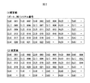
そこで、このような配列構成を下段に示す接続に変更する場合がある。この図ではディスクコントローラ(156)上の全てのポートを使用することになる。これにより各ポートに接続されるHDU(134〜155)の数は少なくなり安定状態にすることが可能である。従来このような配列の変更をする場合は、ディスクアレイのデータを全て他の記録媒体に退避した後、配列構成を変更して、その状態で退避したデータをロードするしか方法が無かった。この方法では、退避するための膨大な記録媒体が必要とされ、退避、回復のための時間も膨大な時間と工数を必要とされた。このような問題を解決するのが以下に示す本発明である。図2に示すように例えばディスクコントローラ側で、ポート番号、列、HDU固有番号の相対関係を示す情報を管理する。
【0014】
これに、実際のRAID構成の論理構成として、例えば、1つのRAID構成(ロジカルユニット(LU))は(0,0)(1,0)(2,0)で構成され、それぞれに物理接続情報としてHDUの001,002,003が接続されているという情報をマッピングする。
【0015】
図1では(0,1)(1,1)(2,1)は他のLUを構成する。同様に(112〜4)、(116〜8)、(120〜2)、(123〜5)で別のLUを構成する。(107)(111)(115)(119)は、予備HDUとする。
【0016】
このような構成のRAIDにおいて、ポートの使用方法を変更して、図1の下段に示す構成にする実施例を示す。
【0017】
本発明では、ディスクが挿入された時、マッピング情報に関連付けられた相対情報と、HDUの固有情報を比較する。例えば、HDU(104)は(134)に挿入される。これをマッピング情報で検証すると、HDUの固有番号は、共に001で同じなのでマッピング情報の変更は発生しない。同様にHDUが挿入されるたびに同様の検証を実施していく。例えば、HDU(108)が(138)に挿入された場合、HUDの固有情報から挿入されたHDUは005番で、005番はマッピング情報から2番目のLUの先頭で以前は(0,1)番地に装着されていたことが確認できる。
【0018】
ここで、マッピング情報に変更が発生することになる。例えば、2番目のLUは、(0,1)(1,1)(2,1)の順で構成されという情報を2番目のLUは、(4,0)(1,1)(2,1)の順で構成されるというように変更される。実際のデータの読み書きでは、どのLUのデータをI/Oするというように命令をだせば、LUの構成はマッピングにより補正されているため、以前と同じデータのI/Oが可能となる。このようにマッピング管理をすることで作業者はHDUの従来の挿入位置を意識することなく組み立てが可能となる。従来技術の問題点であった構成変更も、このような管理をすることでHDUのバックアップを取ることなく、実施可能とすることができる。
【0019】
ここで説明したマッピング情報は、例えばディスクコントローラの不揮発性メモリで管理される。ディスクコントローラが2重化されていれば当然双方で2重に管理される。以上に述べたマッピングの方法は一例にすぎず、実際の使用時には、さらに最適化された多数のマッピング手法が適用可能である。本発明の特徴は、このマッピング技術を有するディスクアレイ装置であり、また、以前のディスクの挿入位置を意識しなくても良い機能を有することを特徴とする発明である。
【0020】
また他の実施例として図3に示す通り、例えば今後の拡張のため筐体をHDUスロットの多い筐体に変更したい場合、従来はバックアップを作成後、新しい筐体で復元する作業が必要であった。この様な場合でも図1、図2で示したようなマッピング情報を移転先の筐体ディスクコントローラにインストールすることで、移転先筐体の自由なHDUスロットに自由にHDUを挿入することが可能で、データの内容も保証することが可能となる。本発明はマッピング情報をHDUに先駆けて移動先のディスクアレイ装置にインストールすることで移動前のディスク情報を再構築可能とすることを特徴とするディスクアレイ装置である。また、マッピング情報をLU単位に切り出して追加、削除することは当該技術者なら容易に可能であり、この利用により、LU単位の移動においても作業者は挿入位置を意識することなく移動が可能となる。
【0021】
また他の実施例として、HDUの固有情報を認識する一実施例としてディスクアレイ装置に新規にHDUが挿入された場合、または、マッピング情報に該当するHDUの情報が登録されていない場合、ディスクアレイ装置は、挿入されたHDUの例えば管理情報にユニークな認識番号を書き込むものとする。HDUの移動範囲をグローバルにするため、この番号は世界レベルで固有であるものとする。このHDUの固有情報を読み込むことで、上記で述べたマッピングが容易に実現可能である。また、ディスクアレイ装置において、HDUの固有情報を読み込んで、その結果を例えば、装置のディスプレイに表示する機能を備えることで、そのHDUの固有番号をユーザが目視でも認識可能となる。
【0022】
さらに、マッピング情報を表示する機能を併用することで、例えば、移動先でHDUを組み込む場合、先にマッピング情報を表示しておき、とりあえず作業者は適当にHDUを挿入すると、その固有番号が認識できるので、マッピング情報と照らし合わせ、正しい位置に挿入し直せばよい。マッピング情報とは、例えば図2の表のようなものである。近年のディスクアレイ装置は表示機能にWebを利用している製品も多数あるので、表示には例えばWebを利用することも可能である。当該技術者なら例えばWeb上にマッピング情報と、挿入されたHDUの情報を表示して、例えば音声ガイド等で変更指示を与えるなどの応用は、容易に類推、実効可能であり、このような技術は、本発明の上に成り立つ発明である。
【0023】
図4にWebを利用した挿入作業の一例を示す。例えばディスクアレイ装置(401)にHDU(402)を挿入する。ディスクアレイ装置(401)とPC(404)はネットワーク回線(403)で接続されており、ディスクアレイ装置のマッピング情報は、ネットワーク経由でPC上のWebでその内容を確認できる。マッピング画面は(404)の様に表示され、その下に、挿入したHDUの固有番号が表示される。そして、さらに、そのHDUの正しい挿入位置が表示、さらに音声でガイドされる。このような機能を利用することによりHDUが100個以上に増えた場合でも、間違えなく、基の配置状態を復元することが容易に可能である。
【0024】
また他の実施例を図5により説明する。例えば、RAID装置の初期設定作業が完了した状態でRAID構成論理情報をHDUに書き込む処理を実施する。RAID構成論理情報とは図5に示すように、LUの1はデータドライブとしてドライブシリアル番号001、002、003で構成され、パリティドライブとしてドライブシリアル番号004により構成される。以下LUの2,3以降についても同様の情報をRAID構成論理情報とする。また、スペアディスクについても、どのシリアル番号のHDUがスペアディスクかを管理する。このRAID構成論理情報を個々のHDUに該当する情報のみ書き込む。
【0025】
例えばシリアル番号001のHDUには、自分のシリアル番号は001番で、LUの1番目を構成するHDUであるという情報、例えば(001、LU1、1)という情報をHDUに書き込む。004では(004,LU1、P)となる。このように全てのHDUに自分の役割を示す情報を書き込んでおく。
【0026】
次に、例えば移設作業でHDUを一旦取り外し、再度装着する場合、まず、全てのディスクを一旦装着する。この時装着する位置は、以前の場所を意識する必要なく自由な位置に装着可能とする。全てのディスクが装着完了した時点でディスクの再構築プログラムを実施する。このプログラムは装着されたHDUから個々のRAID構成論理情報を読み込み、それらを全て読み込んだ時点でRAID構成論理情報と実装位置の相対位置関係情報を生成してディスクコントローラにその情報を引き渡すことで、ディスクコントローラは、以前のデータを復元可能とする。ここで、もし、再構築を実施しようとしたときに、例えばHDUが一つ不足している状況が発生することも想定される。このような場合には、再構築のプログラムが、メッセージとして警告を出力して、該当するHDUの挿入を待つか、スペアのHDU割り当てを要請すればいい。
【0027】
HDUの不良に関しても同様の処理で対処可能である。メッセージは例えば筐体に接続されたPCのWeb画面とか特に手段を限定するものではない。この実施例では初期設置の時HDUに書き込み処理を実施する例を述べたが、例えばHDUの障害により1つを交換した場合なども、交換後に個々に書き込み処理を実施しておけば良い。また、移設作業の前に再度書き込み処理を実施して最新の状態にしておくことも可能である。このような機能を利用することにより保守作業者はHDUの挿入位置を意識することなく移設作業が可能になり誤作業によるデータ破壊を防止することも可能である。
【0028】
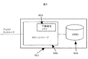
次にHDUへのデータ書き込みの一実施例を図6により説明する。HDUは通常図6に示す通り、HDUコントローラとHDDで構成される。HDUコントローラ上には通常不揮発性のメモリが搭載されており、ここにファームウエア等が書き込まれている。このメモリに前記で述べたRAIDを構成する上で必要な情報を書き込むことで前記の発明は実現可能である。このメモリは不揮発性のため、輸送により脱着しても情報は消えることがないので問題ない。また、新規に使用する場合はイニシャル処理をすれば良い。
【0029】
HDUへの書き込みの他の実施例としては、直接HDDドライブの管理レコードに情報を書き込むことも可能である。通常は一つのHDUには円盤が複数枚使用されているので、例えば1枚目の先頭何バイトかを管理レコードとしてそこに書き込む方式をとることも可能である。管理レコードの管理、書き込み読み込みはHDUコントローラで制御することは容易に可能であり、さらに上位のディスクコントローラで管理することも可能である。
【0030】
次にRAID筐体を移設するとき、搭載されたHDUをすべてはずして搬送する場合の本発明による一実施例を図7に示すフローチャートを用いて説明する。
【0031】
まず、筐体の移設用スイッチを押す。するとディスクコントローラは、接続された全てのHDUに対して、各HDUの実装位置、シリアル番号、RAIDを構成するための情報(自分は、どのロジカルユニットの何番目のディスク他)を書き込む。この情報は全てディスクコントローラにマッピング情報として格納される。全ての書き込み処理が終了すると、作業終了を筐体の表示装置が知らせる。この知らせの出た後、実際にHDUの抜き取り作業を開始する。
【0032】
次に搬送先での移設作業を図8により説明する。まず、HDUをすべて挿入する。次に以前の状態でRAIDを構成するモードのスイッチを押す。すると、ディスクコントローラは、各HDUに書き込まれた実装位置、シリアル番号、RAIDを構成するための情報を読み込む。この情報から作成したマッピング情報と、ディスクコントローラに格納された以前のマッピング情報をコンペアして、実装位置を新しい位置に置き換えてマッピングし直すことで、従来のRAID構成を復元することができる。マッピングの修復が完了したら、通常の運用状態になったことを表示装置により作業者に知らせる。このようにして実際の作業は実施される。
【0033】
移設後の筐体が異なる場合は、ディスクコントローラに格納されたマッピングファイルを新たに移設する筐体のディスクコントローラに事前にインストールしておけば良い。増設の場合も、増設モードでファイルの追加をすることは容易に可能である。
【0034】
上記の実施例はディスクアレイの内部HDU接続にSCSI接続を利用した例で説明したが、ファイバチャネル接続、その他の接続についても本発明は適用可能である。
【0035】
本発明は、上記実施例に限られるものではなく、その主旨に逸脱しない範囲で種々変形して実施することが可能である。
【0036】
【発明の効果】
本発明によれば、1つのディスクコントローラの下に2つ以上のハードディスクユニット(HDU)を持つディスクアレイ装置において、HDUを筐体から抜き出し、再度挿入する時、抜き取り前の実装位置を意識することなく挿入することが可能となり、実装位置不良によるデータ破壊の防止を可能とする効果がある。
【0037】
例えば筐体の切り替え等を実施する時、マッピング機能を利用することで、データの退避、インストールといった入れ替え作業をしなくても、HDUの移設が可能となる効果がある。
【0038】
また、他の効果として例えばディスクアレイ装置の移転作業時に安全のためHDUを取り外して輸送するケースなど、輸送先での作業において、実装位置を意識しなくて良いので作業効率を向上させる効果がある。
【0039】
また、他の効果としてマッピング情報を表示、実際の実装情報と検証する機能によりHDUの抜き取り前の位置を明確に確認可能とるため、上記同様、移設による障害を未然に防止する効果がある。
【図面の簡単な説明】
【図1】ディスクアレイ装置の構成変更実施例
【図2】ディスクアレイ装置のHDUマッピング情報の例
【図3】ディスクアレイ装置の筐体を変更する場合の実施例
【図4】ディスクアレイ装置のHDU挿入支援実施例
【図5】ディスクアレイ装置RAID構成論理情報の例
【図6】ディスクアレイ装置HDU書き込みの実施例
【図7】ディスクアレイ装置HDU交換時の実施例
【図8】ディスクアレイ装置HDU交換時の実施例
【符号の説明】
101… ホストプロセッサ、102… SCSI、ファイバチャネルインタフェース、103… ディスクアレイコントローラ、104〜125… HDU、126… ディスクアレイ装置、201… ホストプロセッサ、202… SCSI、ファイバチャネルインタフェース、203… ディスクアレイコントローラ、204〜225… HDU、226… ディスクアレイ装置
301… ホストプロセッサ、302… SCSI、ファイバチャネルインタフェース、303… ディスクアレイコントローラ、304〜315… HDU、316… ディスクアレイ装置、
321… ホストプロセッサ、322… SCSI、ファイバチャネルインタフェース、323… ディスクアレイコントローラ、324〜335… HDU、336… ディスクアレイ装置、
401… ディスクアレイ装置、402… HDU 、403… ネットワーク回線 、404… PC
601… HDU、602… HDUコントローラ 、603… 不揮発性メモリ 、604… HDDドライブ[0001]
BACKGROUND OF THE INVENTION
The present invention relates to a hard disk unit control method for a disk array device.
[0002]
[Prior art]
A disk array device is usually configured by mounting a plurality of hard disk units (HDUs). One of the features of a conventional disk array is that when a failure occurs in an installed HDU, the HDU is removed, an HDU having no failure is attached, and data can be restored there.
[0003]
Since the conventional technology normally assumes one HDU in which a failure occurs at a time, it is not necessary to manage the individual information of the actually inserted HDU on the disk control side. That is, when an HDU that has been removed is inserted into another position (for example, an adjacent slot that has been vacated), data cannot be matched, and disk information is destroyed.
[0004]
[Problems to be solved by the invention]
As described in the prior art, for example, when there are multiple ports under the controller and multiple HDUs are connected to them, the number of ports to be used and the balance of HDUs connected under the ports When trying to improve the transmission efficiency by adjusting, the conventional technology had to back up all the data, change the configuration, then load the data again and build it.
[0005]
As another problem, in order to avoid troubles due to vibration during the transfer of the disk array device, for example, when transporting the HDU, it is assumed that the HDU is all removed from the housing of the disk array device and transported individually. The In a large-scale disk array device, it is assumed that there are as many as 100 HDUs. When the extracted HDU is reinserted at the transport destination, the mounting position may be mistaken. In the unlikely event that the insertion location is wrong, there is a danger that the data will be destroyed at worst. Unlike a normal HDU failure, it is practically impossible to actually try all combinations.
[0006]
[Means for Solving the Problems]
In the present invention, as means for solving the above problem, a disk controller having a plurality of ports, and at least two or more removable hard disk units connected to any of the plurality of ports and controlled by the disk controller. (HDU), and the disk controller associates the serial number of each HDU with information corresponding to each HDU among the RAID logical configuration information composed of the plurality of HDUs. Stores information for configuring a RAID, and generates a relative position information of the HDU by associating the serial number of the HDU with the mounting position of the HDU when a plurality of the HDUs are mounted on the chassis. Generated by the RAID logical configuration information and the relative positional relationship information generation unit of the plurality of HDUs Mapping information in which the mounting position of the HDU, the serial number of the HDU, and the logical configuration information of the RAID of the HDU are associated with each other is generated from the relative positional relationship information, and before the HDU is removed from the chassis When the relative position information of the generated HDU is different from the relative position information of the HDU after the removed HDU is mounted on the housing, the relative information on the RAID is associated with the logical configuration information of the RAID. The mounting position of the HDU is changed to the mounting position of the HDU corresponding to the serial number of the HDU after being mounted on the chassis, the mapping information is updated, and before the plurality of HDUs are removed from the chassis, Of the mapping information generated by the mapping information generation unit, the mounting position of each HDU and the serial number of each HDU Writing No. and the information corresponding to each HDU among the logical configuration information of the RAID to each HDU.
[0007]
In addition, when the HDU is inserted into the housing, the disk controller displays the mounting position of the HDU corresponding to the serial number of the HDU based on the mapping information generated by the mapping information generation unit. Display on the screen.
[0008]
Further, the disk controller is configured from a plurality of the HDUs based on the mapping information updated by the mapping information update unit when the plurality of HDUs are mounted on the chassis after being removed from the chassis. The RAID logical configuration information to be restored is restored.
[0009]
With these technologies, data can be guaranteed even when the insertion position of the disk is changed, and backup at the time of array change can be made unnecessary. In addition, even when a large amount of HDU is transported separately from the housing during transportation, it is possible to prevent data from being damaged due to a poor insertion position during assembly at the transportation destination.
[0010]
DETAILED DESCRIPTION OF THE INVENTION
Hereinafter, an embodiment of a disk array device according to the present invention will be described in detail with reference to the drawings.
[0011]
FIG. 1 is a disk arrangement diagram according to an embodiment, and the upper part is an arrangement figure before the arrangement change, and the lower part is an arrangement figure after the arrangement change. The present invention is characterized by guaranteeing data in a disk array without using a backup means such as a backup even when the arrangement is changed as shown in FIG. An actual example is shown below.
[0012]
FIG. 1 is a connection diagram of a host (101) and a disk array device (126). The host and the disk array device are connected using SCSI or Fiber Channel (102) as an interface. There is a disk controller (103) in the housing (126) of the disk array device, and there are
[0013]
Therefore, there is a case where such an arrangement is changed to the connection shown in the lower part. In this figure, all ports on the disk controller (156) are used. As a result, the number of HDUs (134 to 155) connected to each port is reduced, and a stable state can be achieved. Conventionally, in order to change the arrangement, there is only a method of saving all the data of the disk array to another recording medium, then changing the arrangement configuration, and loading the saved data in that state. This method requires an enormous recording medium for evacuation and also requires an enormous amount of time and man-hours for evacuation and recovery. The present invention described below solves such a problem. As shown in FIG. 2, for example, on the disk controller side, information indicating the relative relationship between port numbers, columns, and HDU unique numbers is managed.
[0014]
In addition, as a logical configuration of an actual RAID configuration, for example, one RAID configuration (logical unit (LU)) is composed of (0, 0) (1, 0) (2, 0), and each has physical connection information. To map information that HDU's 001, 002 and 003 are connected.
[0015]
In FIG. 1, (0, 1) (1, 1) (2, 1) constitute another LU. Similarly, another LU is configured with (112-4), (116-8), (120-2), and (123-5). (107) (111) (115) (119) are reserved HDUs.
[0016]
In the RAID having such a configuration, an embodiment in which the port usage method is changed to the configuration shown in the lower part of FIG. 1 will be described.
[0017]
In the present invention, when a disc is inserted, the relative information associated with the mapping information is compared with the unique information of the HDU. For example, HDU (104) is inserted into (134). When this is verified with the mapping information, the unique number of the HDU is both 001 and the same, so the mapping information does not change. Similarly, the same verification is performed every time an HDU is inserted. For example, when the HDU (108) is inserted into (138), the HDU inserted from the unique information of the HUD is No. 005, No. 005 is the head of the second LU from the mapping information, and the previous (0, 1) It can be confirmed that it was attached to the address.
[0018]
Here, a change occurs in the mapping information. For example, information indicating that the second LU is configured in the order of (0, 1) (1, 1) (2, 1) indicates that the second LU is (4, 0) (1, 1) (2, It is changed to be configured in the order of 1). In actual data reading and writing, if an instruction is issued to I / O which LU data, the LU configuration is corrected by mapping, so that the same data I / O as before can be performed. By managing the mapping in this way, the operator can assemble without being aware of the conventional insertion position of the HDU. The configuration change that has been a problem of the prior art can be implemented without taking backup of the HDU by performing such management.
[0019]
The mapping information described here is managed by, for example, a nonvolatile memory of the disk controller. If the disk controller is duplicated, it is naturally managed by both sides. The mapping method described above is merely an example, and many more optimized mapping methods can be applied in actual use. A feature of the present invention is a disk array device having this mapping technology, and is an invention characterized by having a function that does not require the user to be aware of the previous disk insertion position.
[0020]
As another embodiment, as shown in FIG. 3, for example, when it is desired to change the chassis to a chassis with many HDU slots for future expansion, it has been necessary to restore a new chassis after creating a backup. It was. Even in such a case, installing the mapping information as shown in FIG. 1 and FIG. 2 in the transfer destination case disk controller allows the HDU to be freely inserted into the free HDU slot of the transfer destination case. Thus, it is possible to guarantee the contents of the data. The present invention is a disk array apparatus characterized in that the disk information before movement can be reconstructed by installing the mapping information in the movement destination disk array apparatus prior to the HDU. In addition, mapping information can be easily extracted and added / deleted by LU in units of LUs. By using this, it is possible for an operator to move LU units without being aware of the insertion position. Become.
[0021]
As another embodiment, when an HDU is newly inserted into the disk array device as an embodiment for recognizing the unique information of the HDU, or when the HDU information corresponding to the mapping information is not registered, the disk array It is assumed that the device writes a unique identification number in, for example, management information of the inserted HDU. In order to make the HDU movement range global, this number shall be unique at the world level. The mapping described above can be easily realized by reading the unique information of the HDU. In addition, the disk array apparatus has a function of reading the unique information of the HDU and displaying the result on the display of the apparatus, for example, so that the user can visually recognize the unique number of the HDU.
[0022]
Furthermore, by combining the function to display the mapping information, for example, when incorporating the HDU at the destination, the mapping information is displayed first, and when the operator inserts the HDU for the time being, the unique number is recognized. It is possible to check the mapping information and insert it again at the correct position. The mapping information is, for example, as shown in the table of FIG. Since there are many products that use the Web for display functions in recent disk array devices, for example, the Web can be used for display. For example, such an engineer can easily apply analogy, such as displaying mapping information and inserted HDU information on the Web, and giving a change instruction using, for example, a voice guide. Is an invention that stands on top of the present invention.
[0023]
FIG. 4 shows an example of insertion work using the Web. For example, the HDU (402) is inserted into the disk array device (401). The disk array device (401) and the PC (404) are connected by a network line (403), and the mapping information of the disk array device can be confirmed on the PC on the PC via the network. The mapping screen is displayed as ( 404 ), and the unique number of the inserted HDU is displayed below it. Further, the correct insertion position of the HDU is displayed and further guided by voice. Even if the HDU is increased to 100 or more by using such a function, it is possible to easily restore the arrangement state of the groups without making a mistake.
[0024]
Another embodiment will be described with reference to FIG. For example, the RAID configuration logical information is written to the HDU in a state where the initial setting work of the RAID device is completed. As shown in FIG. 5, the RAID configuration logical information includes 1 in the LU as drive
[0025]
For example, in the HDU having the
[0026]
Next, when the HDU is temporarily removed and remounted, for example, by relocation work, all the disks are first mounted. The mounting position at this time can be mounted at any position without having to be aware of the previous location. When all the disks have been installed, the disk reconstruction program is executed. This program reads the individual RAID configuration logical information from the mounted HDU, and when all of them are read, generates the RAID configuration logical information and the relative positional relationship information of the mounting position, and delivers the information to the disk controller. The disk controller can restore previous data. Here, it is assumed that, for example, a situation in which one HDU is insufficient occurs when reconstruction is performed. In such a case, the reconstruction program may output a warning as a message and wait for insertion of the corresponding HDU or request a spare HDU assignment.
[0027]
It is possible to deal with an HDU defect by the same processing. For example, the message is not limited to a Web screen of a PC connected to the casing or the means. In this embodiment, the example in which the write process is performed on the HDU at the time of initial installation has been described. However, even when one is replaced due to a failure of the HDU, the write process may be performed individually after the replacement. It is also possible to perform the writing process again before the relocation work so as to keep the latest state. By using such a function, the maintenance worker can perform the relocation work without being aware of the insertion position of the HDU, and can prevent data destruction due to erroneous work.
[0028]
Next, an embodiment of data writing to the HDU will be described with reference to FIG. As shown in FIG. 6, the HDU is usually composed of an HDU controller and an HDD. A nonvolatile memory is usually mounted on the HDU controller, and firmware and the like are written therein. The present invention can be realized by writing information necessary for configuring the above-described RAID in this memory. Since this memory is non-volatile, information is not lost even if it is removed by transportation. In addition, when newly used, initial processing may be performed.
[0029]
As another example of writing to the HDU, it is also possible to directly write information to the management record of the HDD drive. Usually, since a plurality of disks are used for one HDU, for example, it is possible to adopt a method of writing the first several bytes as a management record there. Management, management and writing / reading of management records can be easily controlled by the HDU controller, and can also be managed by a higher-level disk controller.
[0030]
Next, an embodiment according to the present invention will be described with reference to the flowchart shown in FIG. 7 in the case of transferring all mounted HDUs when transferring a RAID chassis.
[0031]
First, press the switch for moving the housing. Then, the disk controller writes the information for configuring the mounting position, serial number, and RAID of each HDU (that is, what number disk of which logical unit, etc.) to all connected HDUs. All of this information is stored as mapping information in the disk controller. When all the writing processes are completed, the display device of the housing notifies the end of the work. After this notification is issued, the HDU extraction operation is actually started.
[0032]
Next, the transfer operation at the transport destination will be described with reference to FIG. First, all the HDUs are inserted. Next, the switch of the mode which comprises RAID in the previous state is pushed. Then, the disk controller reads the information for configuring the mounting position, serial number, and RAID written in each HDU. The conventional RAID configuration can be restored by comparing the mapping information created from this information with the previous mapping information stored in the disk controller and replacing the mounting position with the new position and re-mapping. When the repair of the mapping is completed, the display device informs the operator that the normal operation state has been achieved. In this way, the actual work is performed.
[0033]
If the housing after the transfer is different, the mapping file stored in the disk controller may be installed in advance on the disk controller of the housing to be transferred. Even in the case of expansion, it is easy to add files in the expansion mode.
[0034]
The above embodiment has been described using an example in which SCSI connection is used for internal HDU connection of the disk array. However, the present invention can also be applied to fiber channel connection and other connections.
[0035]
The present invention is not limited to the above-described embodiments, and various modifications can be made without departing from the spirit of the present invention.
[0036]
【The invention's effect】
According to the present invention, in a disk array device having two or more hard disk units (HDUs) under one disk controller, when the HDU is extracted from the housing and reinserted, the mounting position before the extraction is conscious. Therefore, there is an effect that it is possible to prevent data destruction due to a defective mounting position.
[0037]
For example, when switching cases or the like, the mapping function is used, so that there is an effect that the HDU can be relocated without performing a replacement operation such as saving or installing data.
[0038]
In addition, as another effect, for example, a case where the HDU is removed and transported for safety during the transfer operation of the disk array device, for example, there is an effect of improving work efficiency because it is not necessary to be aware of the mounting position in the work at the transport destination. .
[0039]
In addition, as another effect, since the mapping information is displayed and the function of verifying with the actual mounting information makes it possible to clearly check the position before extracting the HDU, as described above, there is an effect of preventing a failure due to relocation.
[Brief description of the drawings]
FIG. 1 shows an example of configuration change of a disk array device. FIG. 2 shows an example of HDU mapping information of the disk array device. FIG. 3 shows an example of changing the housing of the disk array device. Example of HDU insertion support [FIG. 5] Example of disk array device RAID configuration logical information [FIG. 6] Example of disk array device HDU writing [FIG. 7] Example of replacing disk array device HDU [FIG. 8] Disk array device Example of HDU replacement [Explanation of symbols]
DESCRIPTION OF SYMBOLS 101 ... Host processor, 102 ... SCSI, fiber channel interface, 103 ... Disk array controller, 104-125 ... HDU, 126 ... Disk array apparatus, 201 ... Host processor, 202 ... SCSI, Fiber channel interface, 203 ... Disk array controller, 204-225 ... HDU, 226 ... disk array device 301 ... host processor, 302 ... SCSI, fiber channel interface, 303 ... disk array controller, 304-315 ... HDU, 316 ... disk array device,
321 ... Host processor, 322 ... SCSI, Fiber Channel interface, 323 ... Disk array controller, 324 to 335 ... HDU, 336 ... Disk array device,
401 ... Disk array device, 402 ... HDU, 403 ... Network line, 404 ... PC
601... HDU, 602...
Claims (1)
前記複数のポートのいずれかに接続され、前記ディスクコントローラにより制御される、脱着可能な少なくとも2つ以上のハードディスクユニット(HDU)と、
を有し、
前記ディスクコントローラは、
前記各HDUのシリアル番号と、複数の前記HDUにより構成されるRAIDの論理構成情報のうち前記各HDUに該当する情報とが対応付けられたRAIDを構成するための情報を記憶するRAID構成情報記憶部と、
複数の前記HDUが筺体に装着された場合に、前記HDUのシリアル番号と前記HDUの実装位置とを対応付けて前記HDUの相対関係位置情報を生成する相対関係位置情報生成部と、
前記複数のHDUの前記RAIDの論理構成情報および前記相対位置関係情報生成部により生成される前記相対位置関係情報から、前記HDUの実装位置と前記HDUのシリアル番号と前記HDUの前記RAIDの論理構成情報とが対応付けられたマッピング情報を生成するマッピング情報生成部と、
前記HDUが筺体に取り外される前に生成された前記HDUの相対関係位置情報と前記取り外されたHDUが前記筺体に装着された後の前記HDUの相対関係位置情報とが異なる場合に、前記RAIDの論理構成情報に対応付けられた前記HDUの実装位置を、前記筺体に装着後の前記HDUのシリアル番号に対応する前記HDUの実装位置に変更して、前記マッピング情報を更新するマッピング情報更新部と、
複数の前記HDUが前記筺体から取り外される前に、前記マッピング情報生成部により生成された前記マッピング情報のうち、前記各HDUの実装位置と前記各HDUのシリアル番号と前記RAIDの論理構成情報のうち前記各HDUに該当する情報を前記各HDUに書き込む書き込み部と、
前記HDUが前記筺体に挿入された場合に、前記マッピング情報生成部により生成された前記マッピング情報に基づいて、前記HDUのシリアル番号に対応する前記HDUの実装位置を表示画面に表示させる表示制御部と、
複数の前記HDUが前記筺体から取り外された後に前記筺体に装着された場合に、前記マッピング情報更新部により更新された前記マッピング情報に基づいて、複数の前記HDUから構成される前記RAIDの論理構成情報を復元するRAID構成復元部と、
を備えることを特徴とする、ディスクアレイ装置。A disk controller having a plurality of ports;
At least two or more removable hard disk units (HDUs) connected to any of the plurality of ports and controlled by the disk controller;
Have
The disk controller is
RAID configuration information storage for storing information for configuring a RAID in which the serial number of each HDU is associated with the information corresponding to each HDU among the logical configuration information of the RAID configured by the plurality of HDUs And
A relative position information generating unit that generates a relative position information of the HDU by associating the serial number of the HDU and the mounting position of the HDU when a plurality of the HDUs are mounted on a housing;
From the logical configuration information of the RAID of the plurality of HDUs and the relative positional relationship information generated by the relative positional relationship information generation unit, the mounting location of the HDU, the serial number of the HDU, and the logical configuration of the RAID of the HDU a mapping information generating unit which generates mapping information which the information and is associated,
When the relative position information of the HDU generated before the HDU is removed from the chassis and the relative position information of the HDU after the removed HDU is installed in the chassis are different, the RAID A mapping information update unit for updating the mapping information by changing the mounting position of the HDU associated with the logical configuration information to the mounting position of the HDU corresponding to the serial number of the HDU after being mounted on the chassis; ,
Among the mapping information generated by the mapping information generation unit before a plurality of the HDUs are removed from the chassis, the mounting position of each HDU, the serial number of each HDU, and the logical configuration information of the RAID A writing unit for writing information corresponding to each HDU to each HDU;
When the HDU is inserted into the housing, a display control unit that displays the mounting position of the HDU corresponding to the serial number of the HDU on the display screen based on the mapping information generated by the mapping information generation unit When,
When the plurality of HDUs are attached to the chassis after being removed from the chassis, the RAID logical configuration composed of the plurality of HDUs based on the mapping information updated by the mapping information update unit A RAID configuration restoration unit for restoring information;
A disk array device comprising:
Priority Applications (3)
| Application Number | Priority Date | Filing Date | Title |
|---|---|---|---|
| JP2000159552A JP4633886B2 (en) | 2000-05-25 | 2000-05-25 | Disk array device |
| EP01103890A EP1158407A3 (en) | 2000-05-25 | 2001-02-16 | Disk array system |
| US09/790,015 US6877110B2 (en) | 2000-05-25 | 2001-02-20 | Disk array system |
Applications Claiming Priority (1)
| Application Number | Priority Date | Filing Date | Title |
|---|---|---|---|
| JP2000159552A JP4633886B2 (en) | 2000-05-25 | 2000-05-25 | Disk array device |
Publications (3)
| Publication Number | Publication Date |
|---|---|
| JP2001337792A JP2001337792A (en) | 2001-12-07 |
| JP2001337792A5 JP2001337792A5 (en) | 2007-06-21 |
| JP4633886B2 true JP4633886B2 (en) | 2011-02-16 |
Family
ID=18663855
Family Applications (1)
| Application Number | Title | Priority Date | Filing Date |
|---|---|---|---|
| JP2000159552A Expired - Fee Related JP4633886B2 (en) | 2000-05-25 | 2000-05-25 | Disk array device |
Country Status (3)
| Country | Link |
|---|---|
| US (1) | US6877110B2 (en) |
| EP (1) | EP1158407A3 (en) |
| JP (1) | JP4633886B2 (en) |
Families Citing this family (21)
| Publication number | Priority date | Publication date | Assignee | Title |
|---|---|---|---|---|
| US6910083B2 (en) * | 2003-06-26 | 2005-06-21 | Promise Technology, Inc. | Method for detecting channels of a host to which hard disk controllers belong |
| JP4426333B2 (en) * | 2004-02-18 | 2010-03-03 | 株式会社日立製作所 | Disk array device |
| JP2005267038A (en) * | 2004-03-17 | 2005-09-29 | Hitachi Ltd | Operation method for storage system |
| JP2006227818A (en) * | 2005-02-16 | 2006-08-31 | Fujitsu Ltd | Diagnosing method for identification information and input/output device |
| US20060288155A1 (en) * | 2005-06-03 | 2006-12-21 | Seagate Technology Llc | Storage-centric computer system |
| JP2007065984A (en) * | 2005-08-31 | 2007-03-15 | Hitachi Ltd | Storage control device and discrete type storage device |
| JP2007241847A (en) * | 2006-03-10 | 2007-09-20 | Nec Corp | Data storage apparatus |
| JP4920390B2 (en) * | 2006-12-05 | 2012-04-18 | 株式会社東芝 | Storage device |
| US7539799B2 (en) * | 2007-02-08 | 2009-05-26 | Dot Hill Systems Corp. | Method and apparatus for identifying enclosures and devices |
| US20080288414A1 (en) * | 2007-05-15 | 2008-11-20 | Casio Computer Co., Ltd. | Sales data processor and computer readable medium |
| US8131919B1 (en) * | 2007-12-21 | 2012-03-06 | Emc Corporation | Techniques for controlling storage device use by performing a storage device location assessment operation based on a current storage device identifier |
| JP5637552B2 (en) * | 2009-02-17 | 2014-12-10 | 日本電気株式会社 | Storage system |
| JP5333592B2 (en) * | 2009-09-07 | 2013-11-06 | 富士通株式会社 | Member management system, member management apparatus, and program |
| JP5560825B2 (en) * | 2010-03-26 | 2014-07-30 | パナソニック株式会社 | Display device |
| JP5817498B2 (en) * | 2011-12-15 | 2015-11-18 | 富士通株式会社 | Management system, management apparatus, and electronic device management method |
| US8464095B1 (en) * | 2012-11-15 | 2013-06-11 | DSSD, Inc. | Method and system for multi-dimensional raid reconstruction and defect avoidance |
| JP2015082313A (en) * | 2013-10-24 | 2015-04-27 | 富士通株式会社 | Raid configuration management device, raid configuration management program, and raid configuration management method |
| JP5949801B2 (en) | 2014-01-29 | 2016-07-13 | 日本電気株式会社 | Disk array device, control method, and program |
| CN105893282B (en) * | 2015-01-04 | 2019-11-12 | 伊姆西公司 | Hard disk mobile identification method and system |
| JP5910767B2 (en) * | 2015-02-10 | 2016-04-27 | ヤマハ株式会社 | Terminal device and communication system |
| US11347675B2 (en) * | 2020-02-18 | 2022-05-31 | Dell Products L.P. | System and method for dynamically configuring storage mapping |
Citations (6)
| Publication number | Priority date | Publication date | Assignee | Title |
|---|---|---|---|---|
| JPH07261945A (en) * | 1994-03-17 | 1995-10-13 | Hitachi Ltd | Disk array device and disk array dividing method |
| JPH08190461A (en) * | 1995-01-10 | 1996-07-23 | Hitachi Ltd | Disk array system |
| JPH08305499A (en) * | 1995-05-10 | 1996-11-22 | Mitsubishi Electric Corp | Mirror disk control method and mirror disk device |
| JPH096549A (en) * | 1995-06-26 | 1997-01-10 | Hitachi Ltd | Laminated disk array device |
| JPH09330184A (en) * | 1996-06-12 | 1997-12-22 | Hitachi Ltd | Disk housing management system |
| JP2000099283A (en) * | 1998-09-21 | 2000-04-07 | Nec Eng Ltd | Disk array device and its control method |
Family Cites Families (15)
| Publication number | Priority date | Publication date | Assignee | Title |
|---|---|---|---|---|
| US4870643A (en) * | 1987-11-06 | 1989-09-26 | Micropolis Corporation | Parallel drive array storage system |
| JPH0786811B2 (en) * | 1990-06-19 | 1995-09-20 | 富士通株式会社 | Array disk drive drive position confirmation method |
| US5369758A (en) * | 1991-11-15 | 1994-11-29 | Fujitsu Limited | Checking for proper locations of storage devices in a storage array |
| US5511227A (en) * | 1993-09-30 | 1996-04-23 | Dell Usa, L.P. | Method for configuring a composite drive for a disk drive array controller |
| JPH07210336A (en) | 1994-01-17 | 1995-08-11 | Hitachi Ltd | Data storing device |
| US5752257A (en) * | 1994-07-29 | 1998-05-12 | Nomai Sa | Redundant array of removable cartridge disk drives |
| US5822782A (en) * | 1995-10-27 | 1998-10-13 | Symbios, Inc. | Methods and structure to maintain raid configuration information on disks of the array |
| JPH10105345A (en) * | 1996-09-27 | 1998-04-24 | Fujitsu Ltd | Array disk device |
| US6092169A (en) * | 1997-04-02 | 2000-07-18 | Compaq Computer Corporation | Apparatus and method for storage subsystem drive movement and volume addition |
| US5950230A (en) * | 1997-05-28 | 1999-09-07 | International Business Machines Corporation | RAID array configuration synchronization at power on |
| US6567889B1 (en) * | 1997-12-19 | 2003-05-20 | Lsi Logic Corporation | Apparatus and method to provide virtual solid state disk in cache memory in a storage controller |
| US6363457B1 (en) * | 1999-02-08 | 2002-03-26 | International Business Machines Corporation | Method and system for non-disruptive addition and deletion of logical devices |
| US6671776B1 (en) * | 1999-10-28 | 2003-12-30 | Lsi Logic Corporation | Method and system for determining and displaying the topology of a storage array network having multiple hosts and computer readable medium for generating the topology |
| WO2001040925A1 (en) * | 1999-12-02 | 2001-06-07 | Fujitsu Limited | Disk array system and method of expanding storage capacity |
| US6618821B1 (en) * | 2000-01-12 | 2003-09-09 | Hewlett-Packard Development Company, L.P. | Fault tolerant network server having multiple slideably-mounted processing elements sharing a redundant array of independent disks through SCSI isolators |
-
2000
- 2000-05-25 JP JP2000159552A patent/JP4633886B2/en not_active Expired - Fee Related
-
2001
- 2001-02-16 EP EP01103890A patent/EP1158407A3/en not_active Withdrawn
- 2001-02-20 US US09/790,015 patent/US6877110B2/en not_active Expired - Fee Related
Patent Citations (6)
| Publication number | Priority date | Publication date | Assignee | Title |
|---|---|---|---|---|
| JPH07261945A (en) * | 1994-03-17 | 1995-10-13 | Hitachi Ltd | Disk array device and disk array dividing method |
| JPH08190461A (en) * | 1995-01-10 | 1996-07-23 | Hitachi Ltd | Disk array system |
| JPH08305499A (en) * | 1995-05-10 | 1996-11-22 | Mitsubishi Electric Corp | Mirror disk control method and mirror disk device |
| JPH096549A (en) * | 1995-06-26 | 1997-01-10 | Hitachi Ltd | Laminated disk array device |
| JPH09330184A (en) * | 1996-06-12 | 1997-12-22 | Hitachi Ltd | Disk housing management system |
| JP2000099283A (en) * | 1998-09-21 | 2000-04-07 | Nec Eng Ltd | Disk array device and its control method |
Also Published As
| Publication number | Publication date |
|---|---|
| EP1158407A3 (en) | 2008-01-30 |
| US20010049800A1 (en) | 2001-12-06 |
| EP1158407A2 (en) | 2001-11-28 |
| JP2001337792A (en) | 2001-12-07 |
| US6877110B2 (en) | 2005-04-05 |
Similar Documents
| Publication | Publication Date | Title |
|---|---|---|
| JP4633886B2 (en) | Disk array device | |
| US8117409B2 (en) | Method and apparatus for backup and restore in a dynamic chunk allocation storage system | |
| JP3575964B2 (en) | Disk array device | |
| JP4493321B2 (en) | Disk array device and data saving method | |
| JPWO2006123416A1 (en) | Disk failure recovery method and disk array device | |
| US7249278B2 (en) | Disk array apparatus and method for expanding storage capacity | |
| US7571291B2 (en) | Information processing system, primary storage device, and computer readable recording medium recorded thereon logical volume restoring program | |
| EP1956489A2 (en) | Storage control unit and data management method | |
| US7620786B2 (en) | Storage recovery using a delta log | |
| US20060077726A1 (en) | Data transfer method, storage apparatus and computer-readable storage medium | |
| GB2375847A (en) | Protection and restoration of RAID configuration information in disaster recovery process | |
| AU2010256179B2 (en) | Method and device for reading and writing a memory card | |
| JP2005222404A (en) | Storage control subsystem having virtual storage unit | |
| US20050033933A1 (en) | Systems and methods for modifying disk drive firmware in a raid storage system | |
| JPH10254631A (en) | Computer system | |
| US20090083503A1 (en) | System of creating logical volume and method thereof | |
| US6606693B1 (en) | Method and system for long-term digital data storage | |
| JP2002373059A (en) | Method for recovering error of disk array, and controller and device for disk array | |
| CN103605587A (en) | Tape library data backup and filing method | |
| US20090259812A1 (en) | Storage system and data saving method | |
| JP2000056934A (en) | Storage subsystem | |
| JPH0962586A (en) | Information processor and data processing method for this processor | |
| JPH06119125A (en) | Disk array device | |
| CN112784101B (en) | Video data storage method and device and data storage equipment | |
| JP2005149248A (en) | Metadata restoration system, method thereof, storage device and program therefor |
Legal Events
| Date | Code | Title | Description |
|---|---|---|---|
| RD01 | Notification of change of attorney |
Free format text: JAPANESE INTERMEDIATE CODE: A7421 Effective date: 20060418 |
|
| RD03 | Notification of appointment of power of attorney |
Free format text: JAPANESE INTERMEDIATE CODE: A7423 Effective date: 20070425 |
|
| A521 | Request for written amendment filed |
Free format text: JAPANESE INTERMEDIATE CODE: A523 Effective date: 20070509 |
|
| A621 | Written request for application examination |
Free format text: JAPANESE INTERMEDIATE CODE: A621 Effective date: 20070509 |
|
| RD04 | Notification of resignation of power of attorney |
Free format text: JAPANESE INTERMEDIATE CODE: A7424 Effective date: 20070718 |
|
| RD04 | Notification of resignation of power of attorney |
Free format text: JAPANESE INTERMEDIATE CODE: A7424 Effective date: 20090209 |
|
| A977 | Report on retrieval |
Free format text: JAPANESE INTERMEDIATE CODE: A971007 Effective date: 20100303 |
|
| A131 | Notification of reasons for refusal |
Free format text: JAPANESE INTERMEDIATE CODE: A131 Effective date: 20100317 |
|
| A521 | Request for written amendment filed |
Free format text: JAPANESE INTERMEDIATE CODE: A523 Effective date: 20100510 |
|
| A131 | Notification of reasons for refusal |
Free format text: JAPANESE INTERMEDIATE CODE: A131 Effective date: 20100628 |
|
| A521 | Request for written amendment filed |
Free format text: JAPANESE INTERMEDIATE CODE: A523 Effective date: 20100820 |
|
| TRDD | Decision of grant or rejection written | ||
| A01 | Written decision to grant a patent or to grant a registration (utility model) |
Free format text: JAPANESE INTERMEDIATE CODE: A01 Effective date: 20101026 |
|
| A01 | Written decision to grant a patent or to grant a registration (utility model) |
Free format text: JAPANESE INTERMEDIATE CODE: A01 |
|
| A61 | First payment of annual fees (during grant procedure) |
Free format text: JAPANESE INTERMEDIATE CODE: A61 Effective date: 20101118 |
|
| R150 | Certificate of patent or registration of utility model |
Ref document number: 4633886 Country of ref document: JP Free format text: JAPANESE INTERMEDIATE CODE: R150 Free format text: JAPANESE INTERMEDIATE CODE: R150 |
|
| FPAY | Renewal fee payment (event date is renewal date of database) |
Free format text: PAYMENT UNTIL: 20131126 Year of fee payment: 3 |
|
| LAPS | Cancellation because of no payment of annual fees |