JP4632517B2 - Transmission / reception wave phasing method and ultrasonic diagnostic apparatus - Google Patents
Transmission / reception wave phasing method and ultrasonic diagnostic apparatus Download PDFInfo
- Publication number
- JP4632517B2 JP4632517B2 JP2000340700A JP2000340700A JP4632517B2 JP 4632517 B2 JP4632517 B2 JP 4632517B2 JP 2000340700 A JP2000340700 A JP 2000340700A JP 2000340700 A JP2000340700 A JP 2000340700A JP 4632517 B2 JP4632517 B2 JP 4632517B2
- Authority
- JP
- Japan
- Prior art keywords
- sound speed
- medium
- delay time
- medium sound
- phasing
- Prior art date
- Legal status (The legal status is an assumption and is not a legal conclusion. Google has not performed a legal analysis and makes no representation as to the accuracy of the status listed.)
- Expired - Fee Related
Links
Images


Landscapes
- Ultra Sonic Daignosis Equipment (AREA)
- Measurement Of Velocity Or Position Using Acoustic Or Ultrasonic Waves (AREA)
Description
【0001】
【発明の属する技術分野】
本発明は、医療診断に用いる超音波診断装置に係り、特に、超音波の送受波信号の焦点合せを行なう整相処理に関する。
【0002】
【従来の技術】
超音波診断装置は、被検体の表面に超音波探触子を当て、その探触子から被検体に超音波を送信するとともに、被検体内部からの反射波を受信し、その受信信号に基づいて被検体の各部の状態を断層像などの画像により表示して診断に供するものである。一般に、超音波探触子は、複数の振動子を等間隔で直線状、曲線状あるいは面状に配列して形成されている。そして、複数の振動子の内から動作させる振動子群を選択して超音波の送受信が行なわれる。このように選択された振動子群により形成された口径を、例えば順次移動することによってビームを形成する。また、セクタ走査型探触子においては、口径移動は行なわずに、ビームを偏向して走査することが行なわれる。
【0003】
選択された口径の振動子群を駆動するにあたり、各振動子に供給する送波信号を遅延して供給タイミングをずらし、各振動子から放射される超音波を所望の部位(焦点)に収束させる整相処理が行なわれる。同様に、被検体からの反射波(反射エコー)は口径を形成する各振動子によって受信され、その受信信号は増幅された後、各受波信号を遅延する処理を行ない、所望の部位から同一時に反射された波形成分の位相を合せる整相処理が行なわれる。そして、整相処理された各受信信号を加算して十分大きな信号にした後、圧縮処理、フィルタリング処理、γ補正などの信号処理をした後、座標変換及び補間などのスキャン変換をして画像として表示するようになっている。
【0004】
上述した送波整相処理及び受波整相処理における各信号の遅延時間は、各振動子から焦点までの距離の差を超音波の伝播媒質の音速で割って時間に変換したものとなる。伝播媒質の音速としては、通常、仮定した設定音速を用いる。しかし、媒質である生体組織は、音速が均一でないことがあり、また個人差があるため、設定音速と実際の計測時の音速とに誤差がありうる。このような音速差があると、焦点調整が適切に行なわれず、得られる画像の質が劣ることになる。
【0005】
このような問題に対応するため、従来、特開平6−269447号公報には、生体組織中の超音波の伝播速度を適切に推定する方法が提案されている。これによれば、超音波が伝播する媒質を、音速を含む様々な係数で仮定するとともに、伝播する波形の変形を仮定した媒質係数含む理論式によって算出し、実測した波形と照合して媒質音速を含む係数を推定することにより、媒質音速の推定精度を高めるようにしている。
【0006】
また、特開平2−274235号公報には、コンソールなどの入力手段により操作者が媒質音速を指示、修正して最適な整相処理を行なうことが提案されている。また、特願平4−252576号には、人体を不均一媒質とみなし、被検体に応じて遅延時間の調整を行なうことにより、断層像上のフォーカスが合っていない領域で自動的にフォーカスを合せることが提案されている。
【0007】
【発明が解決しようとする課題】
しかしながら、特開平6−269447号公報に記載された方法は、媒質を仮定しなければならず、しかも演算が煩雑で、かつ実測波形と照合しなければならないので、処理に時間がかかる。そのため、被検体の媒質音速に適応させて設定音速を調整して計測を行なう適応計測には必ずしも適していない。
【0008】
また、特開平2−274235号公報に記載された方法は、媒質音速を自動的に推定する方法ではないことから、操作者が負担に感じるとともに、正確性に欠ける問題がある。また、特願平4−252576号の方法は、媒質音速に着目した方法ではないため、全体的に良好な画像を得難いという問題がある。
【0009】
本発明が解決しようとする課題は、整相処理に用いる設定音速を実際の媒質音速と同一又は近い値に自動的に調整することができ、被検体に応じた適応計測を可能にすることにある。
【0010】
【課題を解決するための手段】
本発明に係る整相方法は、配列された複数の振動子から被検体内に送波された超音波の反射波を前記各振動子により受波し、該受波した複数の受波信号を被検体の媒質に対応して定められた設定音速に基づいて遅延させて整相し、該整相された複数の受信信号に基づいて設定音速と実際の媒質音速との誤差を推定し、該推定誤差に基づいて前記媒質音速を推定する処理を、前記被検体の複数の計測領域について行ない、該各計測領域について得られた複数の媒質音速の推定値の確からしさを評価し、最も評価の高い媒質音速推定値を前記複数の領域に対する共通の設定音速として設定することを特徴とする。
【0011】
このような整相方法によれば、実際の被検体について超音波計測を行ない、整相された複数の受信信号に基づいて設定音速と実際の媒質音速との誤差を推定し、その誤差に基づいて設定音速を補正するようにしていることから、簡単な操作により適応計測を実現することができる。
【0012】
ここで、一般に、超音波診断においては、被検体の一定の広がりを有する複数の領域あるいは注目領域について超音波計測を実行し、これにより得られた音響情報に基づいて画像を構成する。この場合に、各計測領域ごとに媒質音速の推定値が異なることがしばしばあり、これに応じて各計測領域ごとに設定音速を調整又は設定することは可能であるが、煩雑になることは避けられない。
【0013】
そこで、複数の領域の全領域あるいは注目領域について得られた媒質音速推定値の中から、代表的な媒質音速を選定して各領域に共通の単一の媒質音速を設定するようにすれば、簡便であり、かつそれらの領域にわたってシャープな整相を行なうことができ、均質な画質の画像を得ることができる。
【0014】
このような課題は、超音波計測により得られた複数の媒質音速推定値について確からしさを評価し、最も評価の高い媒質音速推定値を前記複数の領域に対する共通の設定音速として設定することにより解決できる。
【0015】
ここで、確からしさを評価する方法の具体例としては、次に述べる評価関数による方法がある。ところで、1つの計測領域について計測される複数の受波信号は、設定音速に基づいてそれぞれ定められる遅延時間に応じて遅延することにより整相される。つまり、設定した焦点で反射された超音波が口径を形成する各振動子に入射するタイミングは、各振動子の配列位置に応じて超音波の伝播距離が異なるためにずれる。そこで、各振動子により受信された受波信号の時間軸を一致させるため、伝播距離が最も長い受波信号に対して伝播距離が短い受波信号を適宜遅延させて、受波信号の位相を一致させる整相処理が行なわれる。このときの遅延時間は、伝播距離と伝播媒質の音速に基づいて設定するが、媒質が不均一の場合は整相しても受波信号の位相がずれることになる。そこで、受波信号の位相ずれを計測して遅延時間の誤差を推定し、その推定誤差に基づいて整相に係る遅延時間を補正して、媒質に適応した遅延時間(以下、適応遅延時間ともいう。)に調整することが行なわれている。この適応遅延時間は、振動子の配列方向(アレイ方向)を横軸にしてプロットすると、上に凸状の2次曲線分布を有するものとなる。
【0016】
ところで、遅延誤差に基づいて補正した適応遅延時間分布は、設定時の遅延時間分布に対して全体的に傾きθを有する場合がある。このような現象は、例えば、高エコー(反射率が高い)の部位が存在する場合に生ずる。このような傾きθがある適応遅延時間分布に基づいて調整すると、高エコーの部位に対してフォーカス(焦点合せ)を行なうことになり、本来の超音波ビーム方向からずれた方向にビームを通過させることになる。そこで、傾きθが大きな補正後の遅延時間分布となる領域の媒質音速推定値は、確からしさが低いといえる。
【0017】
一方、受波信号の強度Aが大きいほど、確からしさが高いといえる。また、各受波信号について求めた適応遅延時間は一般に分散するが、その分散幅dが大きい場合は、確からしさが低いといえる。なお、分散幅dは、設定時の遅延時間分布に対する適応遅延時間分布の差異の絶対値でもよい。以上のことから、各領域について下記式(1)の評価関数Kを設定し、Kが最大の領域の適応遅延時間分布に対応する媒質音速を最も確からしいと評価する。
K=A/α+β/d+γ/θ (1)
式(1)におけるα、β、γは、それぞれ任意の係数であり、各評価項に対して適当な重み付けを行なう係数である。
【0018】
さらに、最も評価の高い媒質音速推定値に係る評価が一定の基準に達しない場合は、各領域の媒質音速推定値に基づいて各領域の設定遅延時間をそれぞれ定めて超音波計測を繰返すか、装置の設定高速のままで繰り返すことが好ましい。例えば、閾値Kthを設定し、評価関数Kが閾値Kthを超えるまで繰返す。なお、この繰り返しには、一定の制限回数を定めることができる。
【0019】
上述の整相方法を適用した超音波診断装置は、次の構成により実現できる。すなわち、被検体との間で超音波を送受信する複数の振動子が配列されてなる探触子と、該探触子の各振動子に供給する送波信号を被検体の媒質に対応して定められた設定音速に基づいてそれぞれ遅延させて出力する送波整相手段と、前記各振動子から出力される受波信号を前記設定遅延時間に基づいてそれぞれ遅延して出力する受波整相手段と、該受波整相手段から出力される受信信号に基づいて画像を生成して画像表示手段に表示させる画像処理手段とを備えてなる超音波診断装置において、前記受波整相手段は、複数の前記受波信号を前記設定遅延時間に基づいてそれぞれ遅延して出力する信号遅延手段と、該信号遅延手段から出力される複数の前記受波信号に基づいて前記被検体の媒質音速推定値を求める媒質音速推定手段と、前記被検体の複数の計測領域について求められる複数の前記媒質音速推定値について確からしさを評価し、最も評価の高い媒質音速推定値を選択して前記複数の計測領域に共通の設定音速として設定する代表音速選択手段とを備えてなることを特徴とする。
【0020】
この場合において、前記媒質音速推定手段は、前記信号遅延手段から出力される複数の前記受波信号の遅延誤差を推定する誤差推定手段と、複数の媒質音速と該各媒質音速に対応する複数の参照遅延時間とが格納された記憶手段と、前記設定遅延時間に推定遅延誤差を加算した適応遅延時間に一定の許容範囲で一致する前記参照遅延時間を前記記憶手段から選択する比較手段と、該選択した参照遅延時間に対応する媒質音速を媒質音速推定値として求める媒質音速選択手段とを備えてなるものとすることができる。
【0021】
【実施の形態】
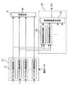
以下、本発明の整相方法を適用してなる超音波診断装置の実施の形態に基づいて本発明を説明する。図1に本実施形態の特徴部である受波整相部のブロック構成図を示し、図2に超音波診断装置の全体構成図を示す。
【0022】
図2に示すように、超音波診断装置は、超音波探触子1と、口径選択スイッチ2と、送受波分離回路3と、送波回路4及び送波整相回路5と、受波回路6と、アナログディジタルコンバータ(ADC)7と、受波整相部8と、加算部9と、信号処理部10と、表示部11と、サンプリング信号発生手段12とを備えて構成されている。受波整相部8、加算部9、信号処理部10は、ディジタル信号処理手段によって形成されている。
【0023】
超音波探触子1は、複数の振動子を直線状に配列して形成されている。そして、口径選択スイッチ2により選択された振動子を駆動して被検体に超音波を送波するとともに、被検体からの反射波を選択された振動子によって受波することにより、被検体内部の所望の部位について超音波計測を行なうようになっている。また、口径を移動することによって、超音波ビームを形成するようになっている。なお、セクタ走査型探触子の場合は、口径移動は行なわずに、超音波ビームを偏向してビームを走査するようになっている。
【0024】
送波整相回路5は、選択された口径を形成する複数の振動子に供給する複数の送波信号を、被検体の媒質に対応して定められた設定音速に基づいてそれぞれ遅延させて整相し、各振動子から放射される超音波を所望の焦点に収束させるようにしている。送波回路4は、送波整相回路5から出力される送波信号に基づいて駆動パルスに生成し、この駆動パルスを送受波分離回路3と口径選択スイッチ2を介して各振動子に供給し、被検体内に超音波ビームを放射するようになっている。
【0025】
被検体からの反射エコーは口径を形成する複数の振動子によって受波され、口径選択スイッチ2と送受波分離回路3を介して受波回路6に入力される。受波回路6は入力される複数の受波信号をそれぞれ良好なダイナミックレンジを有する受波信号に増幅する。受波回路6で増幅された複数の受波信号はADC9に入力され、それぞれディジタル信号に変換されて受波整相部8に入力される。
【0026】
受波整相部8は、複数の受波信号を被検体の媒質に対応して定められた設定音速に基づいて遅延させて整相する。つまり、焦点で反射された超音波が各振動子に入射するタイミングは、各振動子の配列位置に応じて超音波の伝播距離が異なるためにずれる。そこで、各振動子により受信された受波信号の時間軸を一致させるため、伝播距離が最も長い受波信号に対して伝播距離が短い受波信号を適宜遅延させる。これにより、受波信号のフォーカス処理が行なわれ、焦点の音響情報を得ることができる。この受波整相部8は、本発明の特徴部に係る部分であり、詳細は後述する。
【0027】
受波整相部8で整相された受波信号は、加算部9において互いに加算されて大きく成長し、信号処理部10に入力される。信号処理部10は、加算部9の出力信号に対して、log圧縮、フィルタリング、γ補正などの周知の信号処理を施し、さらに座標変換や補間等のスキャン変換を施して、表示部11に出力する。このようにして、被検体の一定の広がりを有する領域について超音波計測をすることにより、所望の画像を構成して表示部11に表示して診断に提供する。なお、サンプリング信号発生手段12は、ADC7におけるアナログディジタル変換のためのサンプリング信号を発生する。
【0028】
ここで、本発明の特徴に係る送受波の整相方法について、受波整相部8を例にして詳細に説明する。受波整相における受波信号の遅延時間は、焦点から振動子までの超音波の伝播距離と、伝播媒質の音速に基づいて設定する。しかし、媒質が生体組織の場合は、媒質が不均一であることが多く、また個人差によって被検体の媒質音速が異なってくる。このような場合、設定した媒質音速に基づく設定遅延時間で整相しても、実際の音速が設定媒質音速と異なるので、受波信号の位相がずれ、適切なフォーカス処理ができずに、画質が劣化することになる。受波整相部8は、このような問題を解決するために構成されたものである。
【0029】
図3に、受波整相部8の詳細構成図を示す。図示のように、ディジタル遅延部21と、遅延誤差推定部22と、遅延時間比較部23と、媒質音速選択部24と、ディジタル遅延制御部25と、参照遅延時間記録部27と、参照音速記録部26とを有して構成されている。ディジタル遅延部21は、図3に示すように受波信号に対応した数のディジタル遅延処理(1〜n)31を有して構成され、各ディジタル遅延処理(1〜n)31は、ディジタル遅延制御部25から入力される遅延データ(媒質音速、伝播距離、遅延時間等)に基づいて、それぞれの受波信号を遅延して加算部9に出力するようになっている。
【0030】
遅延誤差推定部22は、図3に示すように、ディジタル遅延処理31から出力される遅延された隣り合う2つのチャンネルの受波信号を取り込んで、受波信号の遅延誤差を検出する複数の遅延誤差検出処理32と、これらにより検出された誤差に基づいて遅延時間誤差を推定する遅延時間誤差推定処理33とを有して構成される。本実施形態における遅延誤差検出処理32は、例えば周知のように、隣接する2つのチャンネルの受波信号間で相互相関を取ることにより、それら2つの受波信号の位相差を検出する。検出された位相差は、遅延誤差推定処理33に入力され遅延誤差の推定がなされる。つまり、本来、実際の媒質音速が設定値と同一で均質であれば、2つの受波信号の位相差は生じないが、媒質音速に不均一があると位相差が生じるから、これに基づいて遅延時間誤差ΔDを推定することができる。この遅延時間誤差ΔDは、チャンネルごとに求められる。
【0031】
このようにして求められた各振動子に対応する遅延時間誤差ΔDは、遅延時間比較部23に入力される。この遅延時間比較部23には、ディジタル遅延制御部25から各振動子に対応した受波信号ごとの設定遅延時間Dが入力され、ここにおいて遅延時間誤差ΔDを補償した適応遅延時間DA=D+ΔDが求められる。この適応遅延時間DAは各振動子に対応した受波信号ごとに求められる。因みに、遅延時間Dを、振動子の配列方向(アレイ方向)を横軸にしてプロットすると、上に凸の2次曲線状の遅延時間分布を有する。この値を基準に補償すべき遅延誤差DAを重畳することにより適応遅延時間DAとなる。遅延時間比較部23は、求めた適応遅延時間DAに一致又は近い参照遅延時間を参照遅延時間記録部26から検索する。参照遅延時間記録部26には、複数の異なる媒質音速に対応して求めた遅延時間データが格納されており、遅延時間比較部23は最も適応遅延時間DAに近い参照遅延時間を選び出す。このとき、参照遅延時間記録部26に記録されている参照遅延時間が離散的な音速値に対応する遅延時間として記録され、かつ格納されている複数の媒質音速のデータが少ない場合は、適応遅延時間DAに一致する参照遅延時間を検索できない場合がある。この場合は、内挿又は外挿法などにより適宜補完して推定する。なお、適応遅延時間DAを2次曲面又は曲線の遅延時間分布で近似し、これに対応させて参照遅延時間を2次曲面又は曲線で近似した遅延時間分布として表わすようにすると、記録する情報量を少なくすることができる。また、遅延時間分布の階差を求めて階差遅延時間列を生成し、これに対して1次直線を当てはめるようにすると、扱う情報量をさらに低減できる。
【0032】
遅延時間比較部23で選択した参照遅延時間は、媒質音速選択部24に入力され、ここにおいて参照媒質音速記録部27を検索し、選択した参照遅延時間に対応する媒質音速を選択する。これにより、実際の媒質音速に適応した音速を推定することができる。つまり、参照媒質音速記録部27には、参照遅延時間記録部26に記録されている参照遅延時間が、いかなる媒質音速によるものかが記録されている。このようにして、媒質音速選択部24で得られた媒質音速の推定値は、設定音速としてディジタル遅延制御部25に送られる。
【0033】
ディジタル遅延制御部25は、媒質音速選択部24で得られた媒質音速の推定値に従って設定音速を変更し、変更された設定音速に基づいて各振動子に対応した受波信号の設定遅延時間を制御する。
【0034】
このように、上述した実施形態によれば、整相処理に用いる設定音速を実際の媒質音速と同一又は近い値に自動的に調整することができ、被検体に応じた適応計測を可能にできる。その結果、被検体が変わっても、また生体組織に不均一な部分が合っても、それに適応して超音波計測を実行することができ、画質の劣化を改善できる。
【0035】
ところで、これまでの説明では、一つの測定領域、すなわち超音波ビームが1ビームで、かつ1深度の超音波計測における媒質音速調整を説明した。しかし、一般には、2次元又は3次元画像を構成するために超音波ビームを深度と方位の両方向に走査して複数の領域の音響情報を計測する。この場合には、各領域に対応する複数の遅延時間誤差及び媒質音速の推定値が得られる。この場合に、各計測領域ごとに媒質音速推定値が異なることがしばしばあり、これに応じて各計測領域ごとに設定音速を調整又は設定することは可能であるが、煩雑になることは避けられない。
【0036】
すなわち、複数の領域の全領域あるいは注目領域について得られた媒質音速推定値の中から、代表的な媒質音速を選定して各領域に共通の単一の媒質音速を設定する方が有用な場合がしばしばある。例えば、ディジタル遅延部21に設定する各受波信号の遅延時間は、媒質を均質であると仮定すると解析的に求まるものであるから、代表的な媒質音速を選択して各領域に共通の媒質音速として設定すれば、計測に係る調整を簡便化できる。しかも、それらの複数の領域あるいは注目領域にわたってシャープな整相を行なうことができ、均質な画質の画像を得ることができる。
【0037】
そこで、媒質音速選択部24は、複数の領域あるいは注目領域について代表的な媒質音速を選定し、各領域に共通の単一の媒質音速を設定する機能を備えている。この機能の実施形態は、基本的には、超音波計測により得られた複数の媒質音速推定値について、確からしさを評価し、最も評価の高い媒質音速推定値を前記複数の領域に対する共通の設定音速として設定する。ここで、確からしさを評価する方法の具体例としては、次に述べる評価関数による方法がある。
【0038】
先に述べたように、適応遅延時間DAを振動子のアレイ方向を横軸にしてプロットすると、上に凸状の2次曲線分布に近似できる。この適応遅延時間DAの近似分布が設定遅延時間の分布に対して、図4に示すように、全体的に傾きθがある場合がある。このような現象は、例えば、高エコー(反射率が高い)の部位が存在する場合に生ずる。このような傾きθがある適応遅延時間分布に基づいて調整すると、高エコーの部位に対してフォーカス(焦点合せ)を行なうことになり、本来の超音波ビーム方向からずれた方向にビームを通過させることになる。そこで、傾きθが大きな補正後の遅延時間分布となる領域の媒質音速推定値は、確からしさが低いといえる。
【0039】
一方、受波信号の強度Aが大きいほど、確からしさが高いといえる。また、各受波信号について求めた適応遅延時間の分散幅dが大きい確からしさが低いといえる。なお、分散幅dは、設定時の遅延時間分布に対する適応遅延時間分布の差異の絶対値でもよい。以上のことから、各領域について前記式(1)の評価関数Kを求め、Kが最大の領域の適応遅延時間分布に対応する媒質音速を最も確からしいと評価する。
【0040】
ここで、最も評価の高い媒質音速推定値に係る評価が一定の基準に達しない場合は、各領域の媒質音速推定値に基づいて各領域の設定遅延時間をそれぞれ定めて超音波計測を繰返すことが好ましい。例えば、閾値Kthを設定し、評価関数Kが閾値Kthを超えるまで繰返す。なお、この繰り返しには、一定の制限回数を定めることができる。
【0041】
このような考え方に基づいて、図5に示す手順により最も確からしい媒質音速推定値を選択する一実施形態を説明する。先ず、ステップS1において、複数の領域(ビーム方位、深度)について超音波計測を開始し、適応遅延時間分布データを収集する。この収集データに基づいて、ステップS2において、式(1)に従って複数の領域の評価関数Kを演算する。そして、ステップS3において、最大の評価関数Kmaxを選択し、これに基づいて媒質音速を前述の方法で推定する。次いで、ステップS4において、選択した評価関数Kmaxが閾値Kthを越えているか否か、つまりKth<Kmaxを判断する。この判断が肯定的であれば、ステップS5に進んで、評価関数Kmaxに対応する媒質音速推定値をディジタル遅延制御部25に送る。これにより、ディジタル遅延制御部25は、媒質音速推定値に基づいて遅延時間データを再計算してディジタル遅延部21にフィードバックして画像化する。
【0042】
一方、ステップS4の判断が否定的な場合は、ステップS6に進んでステップS5と同様に画像化処理をした後、再び計測に戻り、Kth<Kmaxを満たすまで繰返す。この繰り返し回数は、一定の上限回数を決めておき、超えた場合は、例えば初期の設定音速に戻し、その旨を表示部11に出力することが好ましい。
【0043】
図5の評価手順に代えて、図6の評価手順にすることができる。本手順は、計測によっては、推定した媒質音速が大きくばらつくことがあるので、有り得ない媒質音速の推定値が得られた場合、音速(v)及び評価関数の評価項目(A、d、θ)に上限値又は下限値を設け、外れる場合は評価から外すことにより、媒質音速の推定精度を向上させる。例えば、信号強度の下限値AL、分散幅dの上限値dH、遅延時間分布の傾きθの上限値θHをそれぞれ設定し、また、媒質音速の下限値vLと上限値vHを設定する。そして、例えば、ステップS11において、
AL<A、d<dH、θ<θH
の条件を満たす評価関数Kを抽出する。そして、これに基づいて媒質音速の推定値を演算する(S3)。次いで、ステップS12において、
vL<v<vH
の条件を満たす評価関数Kを抽出して、図5のステップS4につなげるようにする。このようにすることにより、一層推定精度を向上することができる。
【0044】
なお、図6の評価手順の条件を満たす評価関数が抽出できない場合は、つまり繰り返し実行しても収束しない場合は、ステップS13又はステップS14において、評価関数の係数α、β、γや上下限値AL、dH、θH、及び音速範囲vL、vHを変更して、計測を繰返すことができる。
【0045】
評価関数の係数及び上記の上下限値は、他の要因、例えば探触子、観測部位及び疾患に応じて調整することが望ましい。例えば、甲状腺などの表在部位、肝硬変、脂肪肝等では、予想される音速範囲、信号強度、遅延時間精度が異なるからである。また、観測部位によって探触子は大体決まってくるから、探触子ごとに評価関数の係数及び上記の上下限値などを決めてもよい。
【0046】
これらの判断条件の変更、調整は、ファジー推論や人工知能によりさらに最適化することができる。特に、探触子、観測部位及び疾患等の計測条件を入力し、ユーザが満足する画像になったとき、その判断条件を装置に認知させる。これにより、探触子、観測部位及び疾患に対応した評価係数、評価項目の閾値、等を自動的に学習し、同じ条件の次の患者に対し、それらの判断条件の振り方、方向性を持つことができ、速やかに最適な設定に移行することができる。
【0047】
例えば、患者が肝硬変であるとすると、一般に肝硬変は通常の装置の設定音速よりも早い音速を有する。また、肝硬変が全体に硬くなっていれば、受波信号の強度の減衰量は和らぐことが予想される。そこで、音速vの範囲を1550m/s<v<1560m/sに設定し、かつALを通常より高めに設定する。その結果、判定条件を満たさなかった場合、満たさない項目の条件を緩めるか、疾患で予想される方向へ変更する。例えば、1550m/s<v<1600m/sに変更し、係数αを小さくする。この変更によって評価が収束し、さらに操作者が良好と判断したときに、それらの条件を本装置に認識させる。これにより、再び同様の患者が被検体となったとき、評価を収束させるときの知識として、αを小さくすること、又は音速条件を早めにするという知識を学習により獲得できる。その結果、最適な条件に早く調整できる。
【0048】
以上説明したように、上記の実施形態によれば、実際の被検体について超音波計測を行ない、整相された複数の受信信号に基づいて設定音速と実際の媒質音速との誤差を推定し、その誤差に基づいて設定音速を補正するようにしていることから、簡単な操作により適応計測を実現することができる。
【0049】
また、複数の領域の全領域あるいは注目領域について得られた媒質音速推定値の中から、代表的な媒質音速を選定して各領域に共通の単一の媒質音速を設定するようにしているから、媒質音速の適応調整が簡便で、かつそれらの領域にわたってシャープな整相を行なうことができるから、均質な画質の画像を得ることができる。
【0050】
上記実施形態では、遅延誤差推定部22は、隣接するチャンネル間の受波信号の相互相関を取ることにより、それらの位相差を検出して遅延時間の誤差を推定する方法について説明したが、本発明はこれに限らず公知の他の方法を適用してもよい。例えば、隣接チャンネル間の整相後の受波信号に受信中心周波数を複素乗算して差周波数成分のみを取りだし、その実部と虚部を除算してtanθより位相差を出す方法が適用できる。また、表示画像において注目領域を設定し、その領域のヒストグラムや、信号強度が最大になるように、各チャンネルの遅延時間を振りながら収束させて求める方法を適用できる。
【0051】
また、媒質音速を推定して遅延データを作り直して画像化したが、その後に遅延誤差推定部22は補正後の遅延時間に基づいて再計測した遅延時間誤差の情報を持っている。注目領域におけるこの個々の素子の遅延誤差を前記推定高速での遅延時間に加算することで遅延時間を補正して整相することにより画像化すると、全体的に平均音速を補正して画像を改善してから、さらに注目領域の画像の質を向上させることができる。
【0052】
また、媒質音速選択部24で推定した媒質音速の推定値を表示部11に表示するようにしてもよい。また、超音波探触子1について、上記実施形態では1次元配列の振動子の例を用いたが、本発明はこれに限らず、リングアレーや2次元配列振動子を用いた2次元画像や3次元画像を構成する装置にも適用できる。
また、本発明は、上述した実施形態に限定されるものではなく、本発明の要旨を逸脱しない範囲で、種々変更することができる。
【0053】
【発明の効果】
以上述べたように、本発明によれば、整相処理に用いる設定音速を実際の媒質音速と同一又は近い値に自動的に調整することができ、被検体に応じた適応計測が可能になる。
【図面の簡単な説明】
【図1】本発明に係る受波整相部の一実施形態のブロック構成図である。
【図2】本発明の超音波診断装置の一実施形態のブロック構成図である。
【図3】図1のディジタル遅延部と遅延誤差推定部の詳細機能を示す図である。
【図4】適応遅延時間の分布の一例を説明する図である。
【図5】複数領域を代表する媒質音速を選択する処理手順の一実施形態を示すフローチャートである。
【図6】複数領域を代表する媒質音速を選択する処理手順の他の実施形態を示すフローチャートである。
【符号の説明】
1 超音波探触子
2 口径選択スイッチ
5 送波整相回路
7 アナログディジタルコンバータ
8 受波整相部
21 ディジタル遅延部
22 遅延時間推定部
23 遅延時間比較部
24 媒質音速選択部
25 ディジタル遅延制御部
26 参照遅延時間記録部
27 参照媒質音速記録部[0001]
BACKGROUND OF THE INVENTION
The present invention relates to an ultrasonic diagnostic apparatus used for medical diagnosis, and more particularly to a phasing process for performing focusing of ultrasonic transmission / reception signals.
[0002]
[Prior art]
The ultrasonic diagnostic apparatus applies an ultrasonic probe to the surface of the subject, transmits ultrasonic waves from the probe to the subject, receives a reflected wave from the inside of the subject, and based on the received signal Thus, the state of each part of the subject is displayed as an image such as a tomographic image for diagnosis. In general, an ultrasonic probe is formed by arranging a plurality of transducers in a linear shape, a curved shape or a planar shape at equal intervals. Then, a transducer group to be operated is selected from the plurality of transducers, and ultrasonic waves are transmitted and received. A beam is formed by, for example, sequentially moving the aperture formed by the transducer group selected in this way. In the sector scanning probe, the beam is deflected and scanned without moving the aperture.
[0003]
When driving the transducer group of the selected diameter, the transmission signal supplied to each transducer is delayed to shift the supply timing, and the ultrasonic wave radiated from each transducer is converged to a desired part (focal point). A phasing process is performed. Similarly, the reflected wave (reflected echo) from the subject is received by each transducer forming the aperture, and the received signal is amplified and then processed to delay each received signal. A phasing process is performed to match the phases of the waveform components that are sometimes reflected. Then, after adding each received signal subjected to the phasing process to a sufficiently large signal, after performing signal processing such as compression processing, filtering processing, and γ correction, scan conversion such as coordinate conversion and interpolation is performed as an image. It is supposed to be displayed.
[0004]
The delay time of each signal in the above-described transmission phasing processing and receiving phasing processing is obtained by converting the difference in distance from each transducer to the focal point by the sound velocity of the ultrasonic propagation medium and converting it into time. As the sound speed of the propagation medium, normally, the assumed set sound speed is used. However, the biological tissue that is a medium may have an error in the set sound speed and the sound speed at the time of actual measurement because the sound speed may not be uniform and there are individual differences. When there is such a sound speed difference, focus adjustment is not performed properly, and the quality of the obtained image is poor.
[0005]
In order to cope with such a problem, Japanese Patent Laid-Open No. 6-269447 has proposed a method for appropriately estimating the propagation speed of ultrasonic waves in a living tissue. According to this, the medium through which the ultrasonic wave propagates is assumed with various coefficients including the sound velocity, and is calculated by a theoretical formula including the medium coefficient assuming the deformation of the propagating waveform, and is compared with the measured waveform to check the medium sound velocity. The estimation accuracy of the medium sound speed is improved by estimating the coefficient including the.
[0006]
Japanese Patent Laid-Open No. 2-274235 proposes that an operator instructs and corrects the medium sound speed by an input means such as a console to perform an optimum phasing process. In Japanese Patent Application No. 4-252576, the human body is regarded as an inhomogeneous medium, and the delay time is adjusted according to the subject, so that the focus is automatically adjusted in an unfocused area on the tomographic image. It has been proposed to combine.
[0007]
[Problems to be solved by the invention]
However, the method described in Japanese Patent Laid-Open No. 6-269447 requires a medium, and the calculation is complicated, and it is necessary to collate with an actually measured waveform, so that processing takes time. Therefore, it is not necessarily suitable for adaptive measurement in which measurement is performed by adjusting the set sound speed in accordance with the medium sound speed of the subject.
[0008]
Further, since the method described in Japanese Patent Laid-Open No. 2-274235 is not a method for automatically estimating the medium sound speed, there is a problem that the operator feels a burden and lacks accuracy. Further, the method of Japanese Patent Application No. 4-252576 is not a method that pays attention to the speed of sound of the medium, so that it is difficult to obtain a good image as a whole.
[0009]
The problem to be solved by the present invention is to automatically adjust the set sound speed used for the phasing process to a value that is the same as or close to the actual medium sound speed, and to enable adaptive measurement according to the subject. is there.
[0010]
[Means for Solving the Problems]
In the phasing method according to the present invention, a reflected wave of an ultrasonic wave transmitted from a plurality of arranged transducers into a subject is received by each transducer, and the received plurality of received signals are received. Delaying and phasing based on a set sound speed determined corresponding to the medium of the subject, estimating an error between the set sound speed and the actual medium sound speed based on the phased received signals, The processing for estimating the medium sound speed based on the estimation error is performed for a plurality of measurement regions of the subject, and the accuracy of the estimated values of the plurality of medium sound speeds obtained for the respective measurement regions is evaluated. A high medium sound speed estimation value is set as a common set sound speed for the plurality of regions.
[0011]
According to such a phasing method, an ultrasonic measurement is performed on an actual subject, an error between a set sound speed and an actual medium sound speed is estimated based on a plurality of phased received signals, and based on the error. Since the set sound speed is corrected, adaptive measurement can be realized by a simple operation.
[0012]
Here, in general, in ultrasonic diagnosis, ultrasonic measurement is performed on a plurality of regions or regions of interest having a certain spread of a subject, and an image is constructed based on the acoustic information obtained thereby. In this case, the estimated value of the medium sound speed is often different for each measurement region, and the set sound speed can be adjusted or set for each measurement region according to this, but it is not complicated. I can't.
[0013]
Therefore, if a representative medium sound speed is selected from the medium sound speed estimation values obtained for all areas of the plurality of areas or the attention area, and a single medium sound speed common to each area is set, It is simple and sharp phasing can be performed over these regions, and an image with uniform image quality can be obtained.
[0014]
Such a problem is solved by evaluating the certainty of a plurality of medium sound speed estimation values obtained by ultrasonic measurement, and setting the highest estimated medium sound speed estimation value as a common set sound speed for the plurality of regions. it can.
[0015]
Here, as a specific example of the method for evaluating the probability, there is a method using an evaluation function described below. By the way, a plurality of received signals measured for one measurement region are phased by being delayed according to delay times respectively determined based on the set sound speed. That is, the timing at which the ultrasonic wave reflected by the set focal point enters each transducer forming the aperture is shifted because the propagation distance of the ultrasonic wave differs depending on the arrangement position of each transducer. Therefore, in order to match the time axis of the received signal received by each transducer, the received signal with the shortest propagation distance is appropriately delayed with respect to the received signal with the longest propagation distance, and the phase of the received signal is adjusted. Phase matching is performed. The delay time at this time is set based on the propagation distance and the sound speed of the propagation medium. If the medium is not uniform, the phase of the received signal will be shifted even if the phase is adjusted. Therefore, the phase shift of the received signal is measured to estimate the delay time error, the delay time related to phasing is corrected based on the estimated error, and the delay time adapted to the medium (hereinafter also referred to as the adaptive delay time). Adjustment). When this adaptive delay time is plotted with the transducer arrangement direction (array direction) as the horizontal axis, the adaptive delay time has an upward convex quadratic curve distribution.
[0016]
By the way, the adaptive delay time distribution corrected based on the delay error may have an overall inclination θ with respect to the delay time distribution at the time of setting. Such a phenomenon occurs, for example, when there is a portion of high echo (high reflectance). When adjustment is made based on such an adaptive delay time distribution with a slope θ, the high-echo part is focused (focused), and the beam is passed in a direction deviated from the original ultrasonic beam direction. It will be. Therefore, it can be said that the medium sound speed estimation value in the region having the corrected delay time distribution with a large slope θ is low in accuracy.
[0017]
On the other hand, the greater the intensity A of the received signal, the higher the probability. In addition, the adaptive delay time obtained for each received signal is generally dispersed, but if the dispersion width d is large, it can be said that the probability is low. Note that the dispersion width d may be an absolute value of the difference in the adaptive delay time distribution with respect to the delay time distribution at the time of setting. From the above, the evaluation function K of the following formula (1) is set for each region, and the medium sound speed corresponding to the adaptive delay time distribution in the region where K is maximum is evaluated as most likely.
K = A / α + β / d + γ / θ (1)
In Equation (1), α, β, and γ are arbitrary coefficients, and are coefficients that appropriately weight each evaluation term.
[0018]
Furthermore, if the evaluation related to the highest estimated sound speed of the medium does not reach a certain standard, the set delay time for each area is determined based on the medium sound speed estimation value of each area, or the ultrasonic measurement is repeated. It is preferable to repeat the setting at the high speed of the apparatus. For example, the threshold value Kth is set, and the process is repeated until the evaluation function K exceeds the threshold value Kth. It should be noted that a certain limited number of times can be determined for this repetition.
[0019]
An ultrasonic diagnostic apparatus to which the above phasing method is applied can be realized by the following configuration. That is, a probe in which a plurality of transducers that transmit and receive ultrasonic waves to and from the subject are arranged, and a transmission signal supplied to each transducer of the probe is associated with the subject's medium. Transmission phasing means for delaying and outputting each of the signals based on a set sound velocity, and receiving phasing for outputting the received signals output from the transducers with delay based on the set delay time. And an image processing means for generating an image on the basis of a received signal output from the wave phasing means and displaying the image on the image display means. The wave phasing means comprises: A signal delay means for delaying and outputting the plurality of received signals based on the set delay time; and a medium sound speed estimation of the subject based on the plurality of received signals output from the signal delay means Medium sound speed estimation means for obtaining a value; A representative sound speed that evaluates the probability of a plurality of medium sound speed estimation values obtained for a plurality of measurement areas of a specimen, selects the highest estimated medium sound speed estimation value, and sets it as a set sound speed common to the plurality of measurement areas And selecting means.
[0020]
In this case, the medium sound speed estimation means includes error estimation means for estimating delay errors of the plurality of received signals output from the signal delay means, a plurality of medium sound speeds, and a plurality of medium sound speeds corresponding to the medium sound speeds. Storage means for storing a reference delay time, comparison means for selecting from the storage means the reference delay time that matches an adaptive delay time obtained by adding an estimated delay error to the set delay time within a certain allowable range, Medium sound speed selection means for obtaining a medium sound speed corresponding to the selected reference delay time as a medium sound speed estimated value may be provided.
[0021]
Embodiment
Hereinafter, the present invention will be described based on an embodiment of an ultrasonic diagnostic apparatus to which the phasing method of the present invention is applied. FIG. 1 shows a block configuration diagram of a wave receiving phasing unit which is a characteristic portion of the present embodiment, and FIG. 2 shows an overall configuration diagram of an ultrasonic diagnostic apparatus.
[0022]
As shown in FIG. 2, the ultrasonic diagnostic apparatus includes an
[0023]
The
[0024]
The
[0025]
The reflected echo from the subject is received by a plurality of transducers forming a diameter, and is input to the wave receiving circuit 6 via the
[0026]
The received wave phasing unit 8 delays a plurality of received signals based on a set sound speed determined corresponding to the medium of the subject, and phasing. That is, the timing at which the ultrasonic wave reflected by the focal point enters each transducer is shifted because the propagation distance of the ultrasonic wave varies depending on the arrangement position of each transducer. Therefore, in order to make the time axes of the received signals received by each transducer coincide with each other, the received signal with the short propagation distance is appropriately delayed with respect to the received signal with the longest propagation distance. As a result, focus processing of the received signal is performed, and focal acoustic information can be obtained. The wave phasing unit 8 is a part related to the characteristic part of the present invention, and details will be described later.
[0027]
The received signals phased by the received wave phasing unit 8 are added to each other by the adding
[0028]
Here, the wave phasing method for transmission and reception according to the feature of the present invention will be described in detail by taking the wave phasing unit 8 as an example. The delay time of the received signal in the received wave phasing is set based on the propagation distance of the ultrasonic wave from the focal point to the vibrator and the sound speed of the propagation medium. However, when the medium is a living tissue, the medium is often non-uniform, and the medium sound speed of the subject varies depending on individual differences. In such a case, even if phasing with the set delay time based on the set medium sound speed, the actual sound speed is different from the set medium sound speed. Will deteriorate. The wave receiving phasing unit 8 is configured to solve such a problem.
[0029]
FIG. 3 shows a detailed configuration diagram of the wave receiving phasing unit 8. As shown in the figure, a
[0030]
As shown in FIG. 3, the delay
[0031]
The delay time error ΔD corresponding to each transducer thus obtained is input to the delay
[0032]
The reference delay time selected by the delay
[0033]
The digital
[0034]
Thus, according to the above-described embodiment, the set sound speed used for the phasing process can be automatically adjusted to a value that is the same as or close to the actual medium sound speed, and adaptive measurement according to the subject can be performed. . As a result, even if the subject changes or the non-uniform portion of the living tissue fits, ultrasonic measurement can be performed adaptively, and image quality degradation can be improved.
[0035]
By the way, in the description so far, the medium sound speed adjustment in one measurement region, that is, one ultrasonic beam and one depth ultrasonic measurement has been described. However, generally, in order to construct a two-dimensional or three-dimensional image, an ultrasonic beam is scanned in both the depth and azimuth directions to measure acoustic information in a plurality of regions. In this case, a plurality of delay time errors and medium sound speed estimates corresponding to each region are obtained. In this case, the estimated sound speed of the medium is often different for each measurement area, and the set sound speed can be adjusted or set for each measurement area according to this, but it is not complicated. Absent.
[0036]
In other words, when it is more useful to select a representative medium sound speed from the medium sound speed estimation values obtained for all areas of the plurality of areas or the attention area, and to set a single medium sound speed common to each area There are often. For example, since the delay time of each received signal set in the
[0037]
Therefore, the medium sound
[0038]
As described above, the adaptive delay time D A Can be approximated to an upward convex quadratic curve distribution. This adaptive delay time D A As shown in FIG. 4, there is a case where there is an overall inclination θ with respect to the distribution of the set delay time. Such a phenomenon occurs, for example, when there is a portion of high echo (high reflectance). When adjustment is made based on such an adaptive delay time distribution with a slope θ, the high-echo part is focused (focused), and the beam is passed in a direction deviated from the original ultrasonic beam direction. It will be. Therefore, it can be said that the medium sound speed estimation value in the region having the corrected delay time distribution with a large slope θ is low in accuracy.
[0039]
On the other hand, the greater the intensity A of the received signal, the higher the probability. Further, it can be said that the probability that the dispersion width d of the adaptive delay time obtained for each received signal is large is low. Note that the dispersion width d may be an absolute value of the difference in the adaptive delay time distribution with respect to the delay time distribution at the time of setting. From the above, the evaluation function K of the equation (1) is obtained for each region, and the medium sound speed corresponding to the adaptive delay time distribution in the region with the maximum K is evaluated as most likely.
[0040]
Here, when the evaluation related to the highest estimated sound speed of the medium does not reach a certain standard, the set delay time for each area is determined based on the medium sound speed estimated value of each area, and the ultrasonic measurement is repeated. Is preferred. For example, the threshold value Kth is set, and the process is repeated until the evaluation function K exceeds the threshold value Kth. It should be noted that a certain limited number of times can be determined for this repetition.
[0041]
Based on such an idea, an embodiment in which the most probable medium sound speed estimation value is selected by the procedure shown in FIG. 5 will be described. First, in step S1, ultrasonic measurement is started for a plurality of regions (beam orientation and depth), and adaptive delay time distribution data is collected. Based on the collected data, the evaluation function K for a plurality of regions is calculated in step S2 according to the equation (1). In step S3, the maximum evaluation function Kmax is selected, and based on this, the medium sound speed is estimated by the method described above. Next, in step S4, it is determined whether or not the selected evaluation function Kmax exceeds the threshold value Kth, that is, Kth <Kmax. If this determination is affirmative, the process proceeds to step S5, and the medium sound speed estimation value corresponding to the evaluation function Kmax is sent to the digital
[0042]
On the other hand, if the determination in step S4 is negative, the process proceeds to step S6, and after imaging processing is performed in the same manner as in step S5, the process returns to measurement again and repeats until Kth <Kmax is satisfied. For the number of repetitions, a predetermined upper limit number is determined, and if it exceeds, it is preferable to return to the initial set sound speed, for example, and output that fact to the display unit 11.
[0043]
Instead of the evaluation procedure of FIG. 5, the evaluation procedure of FIG. 6 can be used. In this procedure, the estimated medium sound speed may vary greatly depending on the measurement. Therefore, when an impossible medium sound speed estimate is obtained, the sound speed (v) and the evaluation function evaluation items (A, d, θ) are obtained. By setting an upper limit value or a lower limit value in the case and deviating from the evaluation if it falls outside, the medium sound speed estimation accuracy is improved. For example, the lower limit value AL of the signal intensity, the upper limit value dH of the dispersion width d, the upper limit value θH of the slope θ of the delay time distribution are respectively set, and the lower limit value vL and the upper limit value vH of the medium sound speed are set. For example, in step S11,
AL <A, d <dH, θ <θH
An evaluation function K that satisfies the following condition is extracted. Based on this, an estimated value of the medium sound speed is calculated (S3). Next, in step S12,
vL <v <vH
An evaluation function K satisfying the above condition is extracted and connected to step S4 in FIG. By doing so, the estimation accuracy can be further improved.
[0044]
If an evaluation function that satisfies the conditions of the evaluation procedure in FIG. 6 cannot be extracted, that is, if it does not converge even if it is repeatedly executed, coefficients α, β, γ and upper and lower limit values of the evaluation function are obtained in step S13 or step S14. The measurement can be repeated by changing AL, dH, θH, and sound velocity ranges vL, vH.
[0045]
It is desirable to adjust the coefficient of the evaluation function and the upper and lower limit values according to other factors such as the probe, the observation site, and the disease. This is because, for example, superficial sites such as the thyroid gland, cirrhosis, fatty liver, and the like differ in expected sound speed range, signal intensity, and delay time accuracy. In addition, since the probe is roughly determined depending on the observation site, the coefficient of the evaluation function and the upper and lower limit values described above may be determined for each probe.
[0046]
The change and adjustment of these judgment conditions can be further optimized by fuzzy inference and artificial intelligence. In particular, when measurement conditions such as a probe, an observation site, and a disease are input and an image that satisfies the user is obtained, the determination condition is made to be recognized by the apparatus. This automatically learns the evaluation coefficient corresponding to the probe, the observation site and the disease, the threshold of the evaluation item, etc., and how to determine the direction and direction of those judgment conditions for the next patient under the same conditions. You can have it, and you can quickly move to the optimal setting.
[0047]
For example, if the patient has cirrhosis, the cirrhosis generally has a sound speed that is faster than the set sound speed of a normal device. Further, if cirrhosis is hardened as a whole, the attenuation of the intensity of the received signal is expected to ease. Therefore, the range of the sound velocity v is set to 1550 m / s <v <1560 m / s, and AL is set higher than usual. As a result, when the determination condition is not satisfied, the condition of the item that is not satisfied is relaxed or changed to a direction expected for the disease. For example, the coefficient α is decreased by changing to 1550 m / s <v <1600 m / s. When the evaluation converges by this change and the operator determines that the evaluation is good, the apparatus is made to recognize these conditions. As a result, when a similar patient becomes a subject again, the knowledge of reducing α or speeding up the sound speed condition can be acquired by learning as knowledge for converging the evaluation. As a result, the optimum conditions can be adjusted quickly.
[0048]
As described above, according to the above embodiment, ultrasonic measurement is performed on an actual subject, and an error between the set sound speed and the actual medium sound speed is estimated based on a plurality of phased reception signals, Since the set sound speed is corrected based on the error, adaptive measurement can be realized by a simple operation.
[0049]
In addition, a representative medium sound speed is selected from the medium sound speed estimation values obtained for all areas of the plurality of areas or the attention area, and a common medium sound speed is set for each area. Since the adaptive adjustment of the medium sound speed is simple and sharp phasing can be performed over these areas, an image with uniform image quality can be obtained.
[0050]
In the above embodiment, the delay
[0051]
Further, although the medium sound speed is estimated and the delay data is recreated and imaged, the delay
[0052]
Further, the estimated value of the medium sound speed estimated by the medium sound
The present invention is not limited to the above-described embodiments, and various modifications can be made without departing from the gist of the present invention.
[0053]
【The invention's effect】
As described above, according to the present invention, the set sound speed used for the phasing process can be automatically adjusted to a value that is the same as or close to the actual medium sound speed, and adaptive measurement according to the subject becomes possible. .
[Brief description of the drawings]
FIG. 1 is a block configuration diagram of an embodiment of a wave receiving phasing unit according to the present invention.
FIG. 2 is a block configuration diagram of an embodiment of the ultrasonic diagnostic apparatus of the present invention.
FIG. 3 is a diagram illustrating detailed functions of a digital delay unit and a delay error estimation unit in FIG. 1;
FIG. 4 is a diagram for explaining an example of an adaptive delay time distribution;
FIG. 5 is a flowchart showing an embodiment of a processing procedure for selecting a medium sound speed representing a plurality of regions.
FIG. 6 is a flowchart showing another embodiment of a processing procedure for selecting a medium sound velocity representing a plurality of regions.
[Explanation of symbols]
1 Ultrasonic probe
2 Caliber selection switch
5 Transmission phasing circuit
7 Analog to digital converter
8 Received wave phasing section
21 Digital delay unit
22 Delay time estimation unit
23 Delay time comparator
24 Medium sound speed selector
25 Digital delay controller
26 Reference delay time recording section
27 Reference medium sound velocity recording unit
Claims (6)
前記受波整相手段は、複数の前記受波信号を前記設定遅延時間に基づいてそれぞれ遅延して出力する信号遅延手段と、該信号遅延手段から出力される複数の前記受波信号に基づいて前記被検体の媒質音速推定値を求める媒質音速算出手段と、前記被検体の複数の計測領域について求められる複数の前記媒質音速推定値を選択して前記複数の計測領域に共通の設定音速として設定する代表音速選択手段とを備えてなることを特徴とする超音波診断装置。The wave phasing means delays a plurality of the received signals based on the set delay time and outputs them based on the plurality of received signals output from the signal delay means. Medium sound speed calculation means for obtaining a medium sound speed estimation value of the subject, and a plurality of medium sound speed estimation values obtained for a plurality of measurement areas of the subject are selected and set as a set sound speed common to the plurality of measurement areas An ultrasonic diagnostic apparatus comprising: a representative sound speed selection means.
Priority Applications (1)
| Application Number | Priority Date | Filing Date | Title |
|---|---|---|---|
| JP2000340700A JP4632517B2 (en) | 2000-11-08 | 2000-11-08 | Transmission / reception wave phasing method and ultrasonic diagnostic apparatus |
Applications Claiming Priority (1)
| Application Number | Priority Date | Filing Date | Title |
|---|---|---|---|
| JP2000340700A JP4632517B2 (en) | 2000-11-08 | 2000-11-08 | Transmission / reception wave phasing method and ultrasonic diagnostic apparatus |
Publications (3)
| Publication Number | Publication Date |
|---|---|
| JP2002143153A JP2002143153A (en) | 2002-05-21 |
| JP2002143153A5 JP2002143153A5 (en) | 2007-12-20 |
| JP4632517B2 true JP4632517B2 (en) | 2011-02-16 |
Family
ID=18815568
Family Applications (1)
| Application Number | Title | Priority Date | Filing Date |
|---|---|---|---|
| JP2000340700A Expired - Fee Related JP4632517B2 (en) | 2000-11-08 | 2000-11-08 | Transmission / reception wave phasing method and ultrasonic diagnostic apparatus |
Country Status (1)
| Country | Link |
|---|---|
| JP (1) | JP4632517B2 (en) |
Families Citing this family (7)
| Publication number | Priority date | Publication date | Assignee | Title |
|---|---|---|---|---|
| JP4817728B2 (en) * | 2005-06-29 | 2011-11-16 | 株式会社東芝 | Ultrasonic diagnostic equipment |
| US9117439B2 (en) * | 2008-03-13 | 2015-08-25 | Supersonic Imagine | Method and apparatus for ultrasound synthetic imagining |
| JP5174604B2 (en) * | 2008-09-30 | 2013-04-03 | 富士フイルム株式会社 | Ultrasonic signal processing apparatus and method |
| JP5854929B2 (en) * | 2012-05-25 | 2016-02-09 | 富士フイルム株式会社 | Ultrasonic diagnostic apparatus, method for determining reliability of set sound speed, and program |
| KR101393512B1 (en) | 2012-07-25 | 2014-05-13 | 서강대학교산학협력단 | Method for estimating speed of ultrasonic waves, method and apparatus for ultrasonic imaging using the estimated speed thereof |
| JP7370903B2 (en) | 2020-02-28 | 2023-10-30 | キヤノン株式会社 | Ultrasonic diagnostic equipment, learning equipment, image processing methods and programs |
| CN118019497A (en) * | 2021-09-27 | 2024-05-10 | 株式会社Luxonus | Image generation method, image generation program, and image generation device |
Citations (9)
| Publication number | Priority date | Publication date | Assignee | Title |
|---|---|---|---|---|
| JPH0341940A (en) * | 1989-07-10 | 1991-02-22 | Fujitsu Ltd | Electronic scanning type ultrasonic transmitting device |
| JPH0521910U (en) * | 1991-09-05 | 1993-03-23 | 横河メデイカルシステム株式会社 | Transceiver propagation time error correction circuit for ultrasonic device |
| JPH0731616A (en) * | 1993-07-26 | 1995-02-03 | Fujitsu Ltd | Ultrasonic diagnostic apparatus |
| JPH08317926A (en) * | 1995-05-26 | 1996-12-03 | Hitachi Medical Corp | Ultrasonic tomography device |
| US5638820A (en) * | 1996-06-25 | 1997-06-17 | Siemens Medical Systems, Inc. | Ultrasound system for estimating the speed of sound in body tissue |
| JPH09224938A (en) * | 1996-02-23 | 1997-09-02 | Toshiba Corp | Ultrasonic diagnostic device and method for optimizing delay time |
| JPH11113900A (en) * | 1997-10-17 | 1999-04-27 | Hitachi Medical Corp | Ultrasonograph |
| JPH11313823A (en) * | 1998-03-06 | 1999-11-16 | Hitachi Medical Corp | Ultrasonic image device |
| WO2001066014A1 (en) * | 2000-03-10 | 2001-09-13 | Hitachi Medical Corporation | Ultrasonic imaging device |
-
2000
- 2000-11-08 JP JP2000340700A patent/JP4632517B2/en not_active Expired - Fee Related
Patent Citations (10)
| Publication number | Priority date | Publication date | Assignee | Title |
|---|---|---|---|---|
| JPH0341940A (en) * | 1989-07-10 | 1991-02-22 | Fujitsu Ltd | Electronic scanning type ultrasonic transmitting device |
| JPH0521910U (en) * | 1991-09-05 | 1993-03-23 | 横河メデイカルシステム株式会社 | Transceiver propagation time error correction circuit for ultrasonic device |
| JPH0731616A (en) * | 1993-07-26 | 1995-02-03 | Fujitsu Ltd | Ultrasonic diagnostic apparatus |
| JPH08317926A (en) * | 1995-05-26 | 1996-12-03 | Hitachi Medical Corp | Ultrasonic tomography device |
| JPH09224938A (en) * | 1996-02-23 | 1997-09-02 | Toshiba Corp | Ultrasonic diagnostic device and method for optimizing delay time |
| US5638820A (en) * | 1996-06-25 | 1997-06-17 | Siemens Medical Systems, Inc. | Ultrasound system for estimating the speed of sound in body tissue |
| JPH11113900A (en) * | 1997-10-17 | 1999-04-27 | Hitachi Medical Corp | Ultrasonograph |
| JPH11313823A (en) * | 1998-03-06 | 1999-11-16 | Hitachi Medical Corp | Ultrasonic image device |
| WO2001066014A1 (en) * | 2000-03-10 | 2001-09-13 | Hitachi Medical Corporation | Ultrasonic imaging device |
| JP4416256B2 (en) * | 2000-03-10 | 2010-02-17 | 株式会社日立メディコ | Ultrasonic imaging device |
Also Published As
| Publication number | Publication date |
|---|---|
| JP2002143153A (en) | 2002-05-21 |
Similar Documents
| Publication | Publication Date | Title |
|---|---|---|
| US9901323B2 (en) | Aberration correction using channel data in ultrasound imaging system | |
| EP2019600B1 (en) | Retrospective dynamic transmit focusing for spatial compounding | |
| EP2285289B1 (en) | Ultrasonic apparatus and control method therefor | |
| JP4795675B2 (en) | Medical ultrasound system | |
| US10463344B2 (en) | Ultrasound diagnostic apparatus and signal processing method thereof for determining an ambient sound velocity | |
| JP5719098B2 (en) | Ultrasonic diagnostic equipment | |
| WO2001066014A1 (en) | Ultrasonic imaging device | |
| JP6419976B2 (en) | Ultrasonic diagnostic apparatus and control method of ultrasonic diagnostic apparatus | |
| JP6266537B2 (en) | Soft tissue cartilage interface detection method, soft tissue cartilage interface detection device | |
| JP6389963B2 (en) | Ultrasonic diagnostic apparatus and control method of ultrasonic diagnostic apparatus | |
| JP3645347B2 (en) | Ultrasonic diagnostic apparatus and delay time optimization method | |
| US10918360B2 (en) | Ultrasound diagnostic apparatus and method for controlling ultrasound diagnostic apparatus | |
| JP4632517B2 (en) | Transmission / reception wave phasing method and ultrasonic diagnostic apparatus | |
| US6383140B1 (en) | Ultrasonic diagnosis device | |
| JP5777604B2 (en) | Ultrasonic diagnostic apparatus, ultrasonic image generation method and program | |
| JP4090370B2 (en) | Ultrasonic imaging apparatus and ultrasonic imaging method | |
| JP2003339698A (en) | Ultrasonic diagnostic equipment | |
| JP2005087266A (en) | Ultrasonic imaging equipment | |
| US11576646B2 (en) | Ultrasound diagnostic apparatus and method for controlling ultrasound diagnostic apparatus | |
| US11373307B2 (en) | Ultrasound diagnostic apparatus and method for controlling ultrasound diagnostic apparatus | |
| JP2014068755A (en) | Ultrasonic inspection apparatus, signal processing method of ultrasonic inspection apparatus, and program | |
| JP4499477B2 (en) | Ultrasonic diagnostic equipment | |
| JP2004223109A (en) | Apparatus and method for picking up ultrasonic image | |
| JP5854929B2 (en) | Ultrasonic diagnostic apparatus, method for determining reliability of set sound speed, and program | |
| JP5925599B2 (en) | Ultrasonic diagnostic apparatus, sound speed derivation method, and program |
Legal Events
| Date | Code | Title | Description |
|---|---|---|---|
| A521 | Request for written amendment filed |
Free format text: JAPANESE INTERMEDIATE CODE: A523 Effective date: 20071101 |
|
| A621 | Written request for application examination |
Free format text: JAPANESE INTERMEDIATE CODE: A621 Effective date: 20071101 |
|
| A977 | Report on retrieval |
Free format text: JAPANESE INTERMEDIATE CODE: A971007 Effective date: 20100730 |
|
| TRDD | Decision of grant or rejection written | ||
| A01 | Written decision to grant a patent or to grant a registration (utility model) |
Free format text: JAPANESE INTERMEDIATE CODE: A01 Effective date: 20101019 |
|
| A01 | Written decision to grant a patent or to grant a registration (utility model) |
Free format text: JAPANESE INTERMEDIATE CODE: A01 |
|
| A61 | First payment of annual fees (during grant procedure) |
Free format text: JAPANESE INTERMEDIATE CODE: A61 Effective date: 20101116 |
|
| R150 | Certificate of patent or registration of utility model |
Free format text: JAPANESE INTERMEDIATE CODE: R150 |
|
| FPAY | Renewal fee payment (event date is renewal date of database) |
Free format text: PAYMENT UNTIL: 20131126 Year of fee payment: 3 |
|
| LAPS | Cancellation because of no payment of annual fees |