JP4630397B2 - Body surface electrocardiograph - Google Patents

Body surface electrocardiograph Download PDF

Info

Publication number
JP4630397B2
JP4630397B2 JP2004108555A JP2004108555A JP4630397B2 JP 4630397 B2 JP4630397 B2 JP 4630397B2 JP 2004108555 A JP2004108555 A JP 2004108555A JP 2004108555 A JP2004108555 A JP 2004108555A JP 4630397 B2 JP4630397 B2 JP 4630397B2
Authority
JP
Japan
Prior art keywords
body surface
electrode
spot
arithmetic circuit
electrocardiogram
Prior art date
Legal status (The legal status is an assumption and is not a legal conclusion. Google has not performed a legal analysis and makes no representation as to the accuracy of the status listed.)
Expired - Fee Related
Application number
JP2004108555A
Other languages
Japanese (ja)
Other versions
JP2005287849A (en
Inventor
昌弘 野村
広雅 豊栖
Original Assignee
ユーカリテック株式会社
Priority date (The priority date is an assumption and is not a legal conclusion. Google has not performed a legal analysis and makes no representation as to the accuracy of the date listed.)
Filing date
Publication date
Application filed by ユーカリテック株式会社 filed Critical ユーカリテック株式会社
Priority to JP2004108555A priority Critical patent/JP4630397B2/en
Publication of JP2005287849A publication Critical patent/JP2005287849A/en
Application granted granted Critical
Publication of JP4630397B2 publication Critical patent/JP4630397B2/en
Anticipated expiration legal-status Critical
Expired - Fee Related legal-status Critical Current

Links

Images

Landscapes

  • Measurement And Recording Of Electrical Phenomena And Electrical Characteristics Of The Living Body (AREA)

Description

本発明は、心臓電気現象を明確に捉えるため、心臓に近い体表面の多くの点から心電位を測定し、測定した心電位を演算してある時間の体表面電位分布図を表示する体表面心電計に関する。  In order to clearly capture the cardiac electrical phenomenon, the present invention measures the cardiac potential from many points on the body surface close to the heart, and calculates the measured cardiac potential to display a body surface potential distribution map for a certain period of time. Regarding electrocardiographs.

体表面心電計は、体内側に心臓を配置している心電位検出体表面領域、すなわち胸部から背中にいたる体表面領域の100ヶ所以上にスポット電極を配設し、すべてのスポット電極から心臓の鼓動に同期して発生する心電位を採取して、採取した複数点の心電位から総合的に心臓の電気現象を判断する体表面電位分布図を作成する。  The body surface electrocardiograph has spot electrodes disposed at 100 or more locations in the body surface area of the electrocardiogram detection body where the heart is placed inside the body, that is, the body surface area from the chest to the back. An electrocardiogram generated in synchronization with the heartbeat is collected, and a body surface potential distribution diagram for comprehensively judging the electrical phenomenon of the heart from a plurality of collected electrocardiograms is created.

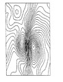
体表面心電計は、例えば図1に示すように、ある時間における心臓付近の体表面である心電位検出体表面領域に誘導される体表面電位分布図を作成する。体表面電位分布図は、心臓電気現象の体表面における電位の分布図である。体表面電位分布図は、すべてのスポット電極で測定された心電位信号を基にして、コンピュータ等の演算回路で演算して求められる。すなわち、ある時間における各々のスポット電極が検出する心電位を、コンピュータのメモリに記憶させ、スポット電極の心電位に基づいて、等電位線を計算し、等電位線を、例えば、数十μVピッチ毎にモニタテレビやプリンター等に表示するものである。  For example, as shown in FIG. 1, the body surface electrocardiograph creates a body surface potential distribution diagram induced in a cardiac potential detection body surface region that is a body surface near the heart at a certain time. The body surface potential distribution diagram is a distribution diagram of potentials on the body surface of the cardiac electrical phenomenon. The body surface potential distribution diagram is obtained by calculation using an arithmetic circuit such as a computer based on the electrocardiogram signals measured at all spot electrodes. That is, the cardiac potential detected by each spot electrode at a certain time is stored in the memory of the computer, the equipotential line is calculated based on the cardiac potential of the spot electrode, and the equipotential line is, for example, a pitch of several tens of μV Each one is displayed on a monitor TV or a printer.

この構造の体表面心電計は、従来の心電計に比較して精密に心臓の電気現象を検査できる。体表面心電計は、従来から多く使用されている12誘導心電計のように、横軸に時間を縦軸に測定位置に誘導される心電波形を表示するのではない。特定の時間において、全てのスポット電極に誘導される心電位から、心電位検出体表面領域に誘導される体表面電位分布図を、あたかも気象図を等圧線で表示して気圧配置を示すかのように、等電位線で表示する。すなわち、体表面電位分布図は、従来の心電波形とは全く異なるので、従来の心電波形を参考にして心臓疾患を判定できない。  The body surface electrocardiograph having this structure can inspect the electrical phenomenon of the heart more precisely than the conventional electrocardiograph. A body surface electrocardiograph does not display an electrocardiographic waveform induced by time on the horizontal axis and the measurement position on the vertical axis, unlike a 12-lead electrocardiograph that has been widely used conventionally. From the electrocardiogram induced at all spot electrodes at a specific time, the body surface potential distribution map induced in the electrocardiogram detection body surface area, as if the meteorological map is displayed with isobaric lines to show the atmospheric pressure arrangement Are displayed with equipotential lines. That is, since the body surface potential distribution diagram is completely different from the conventional electrocardiogram waveform, the heart disease cannot be determined with reference to the conventional electrocardiogram waveform.

また、従来の心電計は、肋骨を基準にして体表面の特定位置にスポット電極を付着し、この部分に誘導される心電波形を表示するので、心臓に極めて近い部分の心電波形を検出できない。とくに、心臓疾患部分にもっとも近い部分の心電波形を検出できない。また、従来の心電計は、電極を付着している体表面の心電波形を表示できるが、電極を付着していない部分に誘導される心電波形を検出でない。心臓の位置は患者により多少異なる。従来の心電計は肋骨等を基準にして電極を体表面に付着しているので、心臓に対して正確な位置に電極を装着することが難しく、患者により電極と心臓との相対位置が異なる。電極に誘導される心電波形は、電極の位置により変化するので、心臓に対する相対位置を正確に特定して心電波形を検出できない検出があった。  In addition, the conventional electrocardiograph attaches a spot electrode to a specific position on the body surface with the rib as a reference, and displays the electrocardiogram waveform induced in this part. It cannot be detected. In particular, the electrocardiographic waveform of the portion closest to the heart disease portion cannot be detected. In addition, the conventional electrocardiograph can display the electrocardiographic waveform of the body surface to which the electrode is attached, but cannot detect the electrocardiographic waveform that is induced in the portion not having the electrode attached. The position of the heart varies slightly from patient to patient. In conventional electrocardiographs, electrodes are attached to the body surface based on the ribs, etc., so it is difficult to attach the electrodes to the heart at an accurate position, and the relative positions of the electrodes and the heart differ depending on the patient. . Since the electrocardiogram waveform induced by the electrode changes depending on the position of the electrode, there is a detection in which the electrocardiogram waveform cannot be detected by accurately specifying the relative position to the heart.

本発明は、このような欠点を解決することを目的に開発されたものである。本発明の重要な目的は、心電位検出体表面領域に複数のスポット電極を装着して、スポット電極を付着しない部分に誘導される心電波形をも正確に検出できる体表面心電計を提供することにある。  The present invention has been developed for the purpose of solving such drawbacks. An important object of the present invention is to provide a body surface electrocardiograph capable of accurately detecting an electrocardiographic waveform induced in a portion where a spot electrode is not attached by mounting a plurality of spot electrodes on the surface area of the electrocardiogram detection body. There is to do.

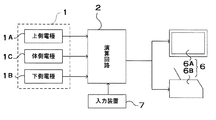
本発明の体表面心電計は、体内側に心臓を配置している心電位検出体表面領域Aの複数点に接触して、体表面に誘導される心電位を検出する複数のスポット電極5を備える電極システム1と、電極システム1の各々のスポット電極5に誘導される心電圧を演算して体表面に誘導される体表面電位分布図を演算する演算回路2と、この演算回路2で演算された体表面電位分布図を表示する外部出力装置6を備える。さらに、体表面心電計は、演算回路2に、心電位検出体表面領域Aであってスポット電極5の間に位置する特定位置を指定できる入力装置7を接続している。演算回路2は、入力装置7で指定された特定位置の時間に対する心電位の変化である心電波形を、特定位置の近傍に位置する複数のスポット電極5に誘導される心電位から演算し、演算した特定位置の心電波形を、横軸を時間、縦 軸を電圧とする心電波形として外部出力装置6で表示する。The body surface electrocardiograph according to the present invention is in contact with a plurality of points in the electrocardiogram detection body surface region A in which the heart is placed inside the body, and detects a plurality of spot electrodes 5 for detecting the electrocardiogram induced on the body surface. An electrode system 1, an arithmetic circuit 2 that calculates a cardiac voltage induced at each spot electrode 5 of the electrode system 1 and calculates a body surface potential distribution map induced on the body surface, and an arithmetic circuit 2 An external output device 6 for displaying the computed body surface potential distribution diagram is provided. Further, the body surface electrocardiograph is connected to the arithmetic circuit 2 with an input device 7 that can designate a specific position that is located between the spot electrodes 5 in the electrocardiogram detection body surface region A. The arithmetic circuit 2 calculates an electrocardiographic waveform, which is a change in electrocardiographic potential with respect to time at a specific position designated by the input device 7, from electrocardiographic potentials induced by a plurality of spot electrodes 5 located near the specific position, The calculated electrocardiographic waveform at a specific position is displayed on the external output device 6 as an electrocardiographic waveform with the horizontal axis representing time and the vertical axis representing voltage .

入力装置7は、マウスとすることができる。心電位検出体表面領域Aに接触するスポット電極5の個数は、100〜1000個とすることができる。演算回路2は、手足に接続している不関電極8に誘導される電位を基準電圧として、心電位の時間に対する変化を演算することができる。  The input device 7 can be a mouse. The number of spot electrodes 5 in contact with the electrocardiogram detection body surface region A can be 100 to 1000. The arithmetic circuit 2 can calculate the change of the cardiac potential with respect to time using the potential induced in the indifferent electrode 8 connected to the limb as a reference voltage.

外部出力装置6は、体表面電位分布図と心電波形を表示するモニタ6Aを備え、モニタ6Aに表示される心電波形で特定の時間を特定し、特定時間における体表面電位分布図を演算回路2で演算してモニタ6Aに表示することができる。さらに、外部出力装置6は、モニタ6Aに表示される心電波形で連続表示時間帯を特定し、連続表示時間帯における体表面電位分布図を演算回路2で演算してモニタ6Aに繰り返し表示することができる。  The external output device 6 includes a monitor 6A that displays a body surface potential distribution map and an electrocardiogram waveform, specifies a specific time from the electrocardiogram waveform displayed on the monitor 6A, and calculates a body surface potential distribution map at the specific time. It can be calculated by the circuit 2 and displayed on the monitor 6A. Furthermore, the external output device 6 specifies the continuous display time zone from the electrocardiogram waveform displayed on the monitor 6A, calculates the body surface potential distribution diagram in the continuous display time zone by the arithmetic circuit 2, and repeatedly displays it on the monitor 6A. be able to.

本発明の体表面心電計は、心電位検出体表面領域に複数のスポット電極を装着して、スポット電極を付着しない部分に誘導される心電波形を正確に検出できる特長がある。それは、本発明の体表面心電計が、複数のスポット電極を接触させている心電位検出体表面領域であって、スポット電極の間に位置する特定位置を入力装置で指定すると共に、入力装置で指定された特定位置の時間に対する心電位の変化である心電波形を、特定位置の近傍に位置する複数のスポット電極に誘導される心電位から演算して表示しているからである。このように、入力装置で指定された特定位置の心電波形を、近傍に位置する複数のスポット電極に誘導される心電位から演算して表示する体表面心電計は、スポット電極を付着していない部分に誘導される心電波形をも正確に検出して表示できる。とくに、体表面電位分布図は心電波形を表示したものではないので、心電位検出体表面領域の特定位置における心電波形を表示できる体表面心電計は、体表面電位分布図と心電波形の双方を比較しながら分析、診断できる特長がある。  The body surface electrocardiograph of the present invention is characterized in that a plurality of spot electrodes are attached to the surface area of the electrocardiogram detection body, and an electrocardiographic waveform induced in a portion where the spot electrodes are not attached can be accurately detected. The body surface electrocardiograph according to the present invention is an electrocardiogram detection body surface region in which a plurality of spot electrodes are in contact with each other, and a specific position located between the spot electrodes is designated by the input device. This is because the electrocardiographic waveform, which is the change in the electrocardiographic potential with respect to the time at the specific position specified in (2), is calculated and displayed from the electrocardiographic potentials induced by the plurality of spot electrodes located near the specific position. As described above, the body surface electrocardiograph that displays the electrocardiogram waveform at a specific position designated by the input device by calculating from the electrocardiograms induced by a plurality of spot electrodes located nearby has the spot electrode attached. It can accurately detect and display the electrocardiographic waveform induced in the part that is not. In particular, the body surface potential distribution chart does not display the electrocardiogram waveform. Therefore, the body surface electrocardiograph capable of displaying the electrocardiogram waveform at a specific position in the surface area of the electrocardiogram detection body is the body surface potential distribution chart It has the feature of being able to analyze and diagnose while comparing both forms.

以下、本発明の実施例を図面に基づいて説明する。ただし、以下に示す実施例は、本発明の技術思想を具体化するための体表面心電計を例示するものであって、本発明は体表面心電計を下記のものに特定しない。  Embodiments of the present invention will be described below with reference to the drawings. However, the following examples illustrate body surface electrocardiographs for embodying the technical idea of the present invention, and the present invention does not specify body surface electrocardiographs as described below.

さらに、この明細書は、特許請求の範囲を理解し易いように、実施例に示される部材に対応する番号を、「特許請求の範囲」、および「課題を解決するための手段の欄」に示される部材に付記している。ただ、特許請求の範囲に示される部材を、実施例の部材に特定するものでは決してない。  Further, in this specification, in order to facilitate understanding of the scope of claims, numbers corresponding to the members shown in the embodiments are indicated in “Claims” and “Means for Solving the Problems”. It is appended to the members shown. However, the members shown in the claims are not limited to the members in the embodiments.

本発明の一実施の形態である体表面心電計を図2と図3に示す。図に示す体表面心電計は、患者の体表面の複数ヶ所に誘導される心電位を検出する複数のスポット電極5を備える電極システム1と、電極システム1のスポット電極5で検出する心電位から体表面に誘導される体表面電位分布図を演算する演算回路2と、この演算回路2で演算された体表面電位分布図を表示する外部出力装置6と、演算回路2に接続している入力装置7とを備える。図2の体表面心電計は、外部出力装置6として、モニタ6Aと、プリンター6Bを備える。外部出力装置と入力装置は、インターネット等の通信回線を介して演算回路に接続することもできる。  A body surface electrocardiograph according to an embodiment of the present invention is shown in FIGS. The body surface electrocardiograph shown in the figure includes an electrode system 1 including a plurality of spot electrodes 5 for detecting a cardiac potential induced at a plurality of locations on a patient's body surface, and a cardiac potential detected by the spot electrodes 5 of the electrode system 1. An arithmetic circuit 2 for calculating a body surface potential distribution map induced on the body surface from the motor, an external output device 6 for displaying the body surface potential distribution map calculated by the arithmetic circuit 2, and an arithmetic circuit 2 And an input device 7. The body surface electrocardiograph shown in FIG. 2 includes a monitor 6A and a printer 6B as the external output device 6. The external output device and the input device can also be connected to the arithmetic circuit via a communication line such as the Internet.

電極システム1を構成する各々のスポット電極5は、図4と図5に示すように、体内側に心臓を配置している心電位検出体表面領域Aの複数点に接触されて、接触点に誘導される心電位を検出する。心電位検出体表面領域Aは、胸部体表面、あるいは胸部体表面から背中体表面にいたる領域である。図3ないし図5の電極システム1は、ベッド3の上面に配設されて仰臥する患者の体表面である背中に接触する下側電極1Bと、患者の体側に接触する体側電極1Cと、患者の上面に接触する上側電極1Aとを備える。下側電極1Bは、一定の間隔で配設している複数のスポット電極5を備えている。下側電極1Bのスポット電極5は、患者の背中の50%以上からほぼ全体の体表面に分布される。上側電極1Aも一定の間隔で配設している複数のスポット電極5を備えており、各々のスポット電極5は胸部体表面の60%以上からほぼ全体の体表面に分布される。体側電極1Cも一定の間隔に配設している複数のスポット電極5を備えており、各々のスポット電極5を体側に接触させる。  As shown in FIGS. 4 and 5, each spot electrode 5 constituting the electrode system 1 is brought into contact with a plurality of points on the surface area A of the electrocardiogram detection body surface A in which the heart is arranged on the inner side of the body. Detect the induced cardiac potential. The electrocardiogram detection body surface region A is a chest body surface or a region from the chest body surface to the back body surface. The electrode system 1 shown in FIGS. 3 to 5 includes a lower electrode 1B that contacts the back, which is a body surface of a patient who is placed on the upper surface of the bed 3, and a body-side electrode 1C that contacts the patient's body, and a patient. And an upper electrode 1A that is in contact with the upper surface. The lower electrode 1B includes a plurality of spot electrodes 5 arranged at regular intervals. The spot electrodes 5 of the lower electrode 1B are distributed over almost the entire body surface from 50% or more of the patient's back. The upper electrode 1A is also provided with a plurality of spot electrodes 5 arranged at regular intervals, and each spot electrode 5 is distributed on the entire body surface from 60% or more of the chest body surface. The body side electrode 1C is also provided with a plurality of spot electrodes 5 arranged at regular intervals, and each spot electrode 5 is brought into contact with the body side.

患者がベッド3に上向きに仰臥して体表面の心電位を検出するとき、下側電極1Bのスポット電極5は患者の背中に接触し、体側電極1Cのスポット電極5は体側に接触し、上側電極1Aのスポット電極5は患者の胸に接触して体表面に誘導される心電位を検出する。患者が上下反転して下向きにベッド3に寝ると、下側電極1Bは患者の胸に接触し、上側電極1Aは患者の背中に接触する。  When the patient lies on the bed 3 and detects the cardiac potential on the body surface, the spot electrode 5 of the lower electrode 1B contacts the patient's back, the spot electrode 5 of the body electrode 1C contacts the body side, and the upper electrode The spot electrode 5 of the electrode 1A detects the cardiac potential induced on the body surface in contact with the chest of the patient. When the patient is turned upside down and lies down on the bed 3, the lower electrode 1B contacts the patient's chest and the upper electrode 1A contacts the patient's back.

図3と図4の体表面心電計は、上側電極1Aをロッド電極10とし、下側電極1Bと体側電極1Cとをクッション電極20としている。体表面心電計は、上側電極をクッション電極とすることも、体側電極をロッド電極とすることも、下側電極をロッド電極とすることもできる。すなわち、体表面心電計は、上側電極と体側電極と下側電極として、ロッド電極とクッション電極とをそれぞれ個別に組み合わせることができる。したがって、上側電極と下側電極と体側電極の全てをロッド電極とすることも、全てをクッション電極とすることもできる。また、体表面心電計は、必ずしも電極を上側電極と下側電極と体側電極とに分離することなく、全体をひとつのロッド電極あるいはクッション電極とすることもできる。この電極は、胸と背中に接触するもの、胸と体側に接触するもの、体側と背中に接触するもの、さらに胸と体側と背中に接触するものとすることができる。  The body surface electrocardiographs of FIGS. 3 and 4 use the upper electrode 1A as the rod electrode 10 and the lower electrode 1B and the body side electrode 1C as the cushion electrode 20. In the body surface electrocardiograph, the upper electrode can be a cushion electrode, the body side electrode can be a rod electrode, and the lower electrode can be a rod electrode. That is, the body surface electrocardiograph can individually combine the rod electrode and the cushion electrode as the upper electrode, the body side electrode, and the lower electrode. Therefore, all of the upper electrode, the lower electrode, and the body electrode can be rod electrodes, or all can be cushion electrodes. In addition, the body surface electrocardiograph may be configured as a single rod electrode or cushion electrode without necessarily separating the electrode into the upper electrode, the lower electrode, and the body electrode. This electrode can be in contact with the chest and back, in contact with the chest and body, in contact with the body and back, and in contact with the chest, body and back.

ロッド電極10は、図3ないし図9に示すように、スポット電極5を、金属ロッドである導電ロッド12としている。ロッド電極10は、この導電ロッド12を患者の体表面に独立して弾性的に押圧して、体表面に誘導される心電位を検出する。  As shown in FIGS. 3 to 9, the rod electrode 10 uses the spot electrode 5 as a conductive rod 12 that is a metal rod. The rod electrode 10 elastically presses the conductive rod 12 against the patient's body surface independently, and detects an electrocardiogram induced on the body surface.

図3ないし図7に示すロッド電極10は、8個の電極ユニット11を備える。8個の電極ユニット11は、2列に4個ずつ配置している。各々の電極ユニット11は、図6の正面図と図7の底面図に示すように、紐状のゴム状弾性体である可動性部材15でもって連結されている。さらに、これらの図に示すロッド電極10は、各列の電極ユニット11の下面に弾性変形プレート16を固定して、この弾性変形プレート16で4個の電極ユニット11を連結している。この弾性変形プレート16は、曲げ方向に弾性を有するゴム板や合成樹脂プレート等の板材やシート材で、互いに隣接する電極ユニット11の間隔を所定の間隔に保持しながら、各電極ユニット11の姿勢を患者の胸面に沿う状態に配置している。  The rod electrode 10 shown in FIGS. 3 to 7 includes eight electrode units 11. Eight electrode units 11 are arranged in two rows by four. As shown in the front view of FIG. 6 and the bottom view of FIG. 7, each electrode unit 11 is connected by a movable member 15 that is a string-like rubber-like elastic body. Furthermore, the rod electrode 10 shown in these drawings has an elastic deformation plate 16 fixed to the lower surface of each row of electrode units 11, and the four electrode units 11 are connected by the elastic deformation plate 16. The elastic deformation plate 16 is a plate or sheet material such as a rubber plate or a synthetic resin plate that has elasticity in the bending direction, and maintains the interval between the electrode units 11 adjacent to each other while maintaining a predetermined interval. Is placed along the patient's chest.

複数の電極ユニット11で構成されるロッド電極10である上側電極1Aは、図3と図4に示すように、吊下機構4で吊り下げて患者の胸の所定の位置に配置される。これらの図に示す吊下機構4は、複数の電極ユニット11を水平の姿勢で吊り下げる上下台4Aと、この上下台4Aを水平の姿勢で上下、左右に移動させる支持台4Bとを備える。複数の電極ユニット11は、吊り紐18を介して上下台4Aから吊り下げられている。上側電極1Aは、上下台4Aを水平の姿勢で移動させて、複数の電極ユニット11からなるロッド電極10を所定の位置に配置する。患者の胸面に配置された上側電極1Aは、その自重により所定の位置に保持される。ただ上側電極1Aは、図4と図6の鎖線で示すように、装着バンド40を介して複数の電極ユニット11からなるロッド電極10を患者にしっかりと装着することもできる。この上側電極1Aは、図6に示すように、最も外側に位置する電極ユニット11に伸縮性の装着バンド40を連結し、この装着バンド40の先端を連結具41を介してベッド3に連結して、これでもって患者にしっかりと装着することができる。  As shown in FIGS. 3 and 4, the upper electrode 1 </ b> A that is the rod electrode 10 composed of a plurality of electrode units 11 is suspended by the suspension mechanism 4 and disposed at a predetermined position on the patient's chest. The suspension mechanism 4 shown in these drawings includes an upper and lower base 4A that suspends the plurality of electrode units 11 in a horizontal posture, and a support base 4B that moves the upper and lower base 4A up and down and left and right in a horizontal posture. The plurality of electrode units 11 are suspended from the upper and lower bases 4 </ b> A via suspension strings 18. The upper electrode 1 </ b> A moves the upper / lower platform 4 </ b> A in a horizontal posture and arranges the rod electrode 10 composed of the plurality of electrode units 11 at a predetermined position. The upper electrode 1A disposed on the chest surface of the patient is held at a predetermined position by its own weight. However, the upper electrode 1 </ b> A can firmly attach the rod electrode 10 composed of the plurality of electrode units 11 to the patient via the attachment band 40, as shown by the chain line in FIGS. 4 and 6. As shown in FIG. 6, the upper electrode 1 </ b> A connects a stretchable mounting band 40 to the outermost electrode unit 11, and connects the tip of the mounting band 40 to the bed 3 via a connector 41. With this, it can be securely attached to the patient.

それぞれの電極ユニット11は、図8と図9に示すように、患者の体表面の複数ヶ所に押圧される複数本の導電ロッド12と、これらの導電ロッド12を出入りできるように装着している電極本体13と、この電極本体13から導電ロッド12を弾性的に押し出すコイルスプリング14とを備える。  As shown in FIGS. 8 and 9, each electrode unit 11 is equipped with a plurality of conductive rods 12 that are pressed against a plurality of locations on the patient's body surface, and these conductive rods 12 can be moved in and out. An electrode body 13 and a coil spring 14 that elastically pushes the conductive rod 12 from the electrode body 13 are provided.

図6ないし図9に示す電極ユニット11は、8本の導電ロッド12を備える。8本の導電ロッド12は、底面の形状を長方形とする電極ユニット11に、2列に4個ずつ配置している。これらの導電ロッド12は、等しい中心間隔(d)で配置されている。図のロッド電極10は、8個の電極ユニット11に各8本の導電ロッド12を配設しているので、全体では64個のスポット電極5を備えている。このロッド電極10は、たとえば、中心間隔(d)を35mmとして、約600cm2の領域の心電位を測定できる。ただ、ロッド電極は、電極ユニットの個数を2〜64とし、導電ロッドの本数、すなわちスポット電極の測定ポイント数を25〜500とし、測定領域を200〜900cm2とし、中心間隔を10〜60mmとすることができる。さらに、ロッド電極は、配置される複数の導電ロッドの中心間隔(d)を、必ずしも全て等しくする必要はなく、患者の上下方向と左右方向とで変更することができ、あるいは、部分的に変更することもできる。  The electrode unit 11 shown in FIGS. 6 to 9 includes eight conductive rods 12. Eight conductive rods 12 are arranged in two rows on each electrode unit 11 having a rectangular bottom shape. These conductive rods 12 are arranged with an equal center interval (d). The rod electrode 10 shown in the figure is provided with 64 spot electrodes 5 as a whole because eight conductive rods 12 are arranged in eight electrode units 11. For example, the rod electrode 10 can measure the cardiac potential in a region of about 600 cm <2> when the center interval (d) is 35 mm. However, in the rod electrode, the number of electrode units is 2 to 64, the number of conductive rods, that is, the number of spot electrode measurement points is 25 to 500, the measurement area is 200 to 900 cm2, and the center interval is 10 to 60 mm. be able to. Further, the rod electrodes do not necessarily have to have the same center interval (d) between the plurality of conductive rods arranged, and can be changed in the vertical and horizontal directions of the patient or partially changed. You can also

複数本の導電ロッド12は、電極本体13から体表面に向かって弾性的に突出しており、患者の体表面を独立して押圧する。これらの導電ロッド12は、電極本体13に出入りできるように連結しているロッド部12Bと、このロッド部12Bの先端部に連結されて体表面に接触して体表面に誘導される心電位を検出する接触電極12Aとを備える。図の導電ロッド12は、ロッド部12Bを金属ロッドとしている。ロッド部12Bは、直径を1.5〜6mm、好ましくは3〜4mmとする金属線である。ロッド部12Bは、細すぎると曲がりやすく、太すぎると摺動抵抗が大きくなってスムーズに出入りさせるのが難しくなる。ロッド部12Bは、SUS304等のステンレス線、表面をメッキしているピアノ線等の曲がり難い金属線が適している。さらに、ロッド部は、円筒状として軽くすることもできる。ただし、ロッド部は、必ずしも金属製のロッドとする必要はなく、たとえば、硬質プラスチックロッドの表面や内面に導電膜をコーティングしたもの、あるいは導電性のあるカーボン繊維をロッド状に成形したものも使用できる。ロッド部12Bは、軸方向に移動できるように電極本体13に装着されて、コイルスプリング14で体表面に向かって押圧される。  The plurality of conductive rods 12 elastically protrude from the electrode body 13 toward the body surface and press the patient's body surface independently. These conductive rods 12 are connected to the rod portion 12B connected to the electrode body 13 so as to be able to enter and exit, and are connected to the tip of the rod portion 12B so as to contact the body surface and induce a cardiac potential induced on the body surface. 12A of contact electrodes to detect. In the illustrated conductive rod 12, the rod portion 12B is a metal rod. The rod portion 12B is a metal wire having a diameter of 1.5 to 6 mm, preferably 3 to 4 mm. If the rod portion 12B is too thin, it is easy to bend, and if it is too thick, the sliding resistance increases and it is difficult to smoothly enter and exit. For the rod portion 12B, a stainless steel wire such as SUS304 or a metal wire that is difficult to bend such as a piano wire plated on the surface is suitable. Further, the rod portion can be lightened as a cylindrical shape. However, the rod part does not necessarily need to be a metal rod. For example, a hard plastic rod surface or inner surface coated with a conductive film, or a conductive carbon fiber molded into a rod shape can be used. it can. The rod portion 12B is attached to the electrode body 13 so as to be movable in the axial direction, and is pressed toward the body surface by the coil spring 14.

接触電極12Aは金属製で、体表面に弾性的に押圧されて、体表面に誘導される心電位を検出する。接触電極12Aは、金属を切削加工し、あるいは鋳造し、あるいはまたプレス加工して製作される。金属製の接触電極12Aは、たとえば、ステンレス、シンチュウ、鉛、銀、塩化銀等の金属で成形することができる。さらに、金属製の接触電極12Aは、安定して心電位を検出するために、接触面12aの表面、あるいは全面に金属メッキ層を設けることができる。金属メッキ層は、金メッキ、白金メッキ、銀メッキ、塩化銀メッキ、ニッケルメッキ、クロームメッキ、シンチュウメッキ、鉛メッキ等が使用できる。さらに、接触電極12Aは、体表面との接触面12aを中央凸に湾曲する湾曲面としている。このように、接触面12aが中央凸に湾曲している接触電極12Aは、体表面に対する角度が変わっても、体表面に常に広い面積で接触できる特長がある。  The contact electrode 12A is made of metal and is elastically pressed against the body surface to detect an electrocardiogram induced on the body surface. The contact electrode 12A is manufactured by cutting, casting, or pressing a metal. The metal contact electrode 12A can be formed of a metal such as stainless steel, Shinchu, lead, silver, or silver chloride. Further, the metal contact electrode 12A can be provided with a metal plating layer on the surface of the contact surface 12a or the entire surface in order to detect the cardiac potential stably. As the metal plating layer, gold plating, platinum plating, silver plating, silver chloride plating, nickel plating, chrome plating, Shinchu plating, lead plating, or the like can be used. Furthermore, the contact electrode 12A has a contact surface 12a with the body surface as a curved surface that curves in a central convex shape. As described above, the contact electrode 12A having the contact surface 12a curved in the center convex shape has a feature that it can always contact the body surface over a wide area even if the angle with respect to the body surface changes.

電極本体13は、図9において、下方を開口している箱形のケース50と、2枚の絶縁性の板材51とを備えている。2枚の板材51には、これを貫通して導電ロッド12のロッド部12Bを出入自在に挿通している。2枚の板材51は、互いに平行に配設されており、対向する位置に挿通孔51Aを開口して、これらの挿通孔51Aに導電ロッド12のロッド部12Bを挿通している。2枚の板材51は、間に配設された複数本の支柱52に固定されて所定の間隔に保持されている。ロッド部12Bは、その中間部分であって、2枚の板材51の間に位置して固定リング55を固定しており、この固定リング55で導電ロッド12が電極本体13から抜けるのを阻止すると同時に、導電ロッド12の突出量を特定している。さらに、2枚の板材51には、電極本体13に出入りするロッド部12Bの摺動抵抗を小さくするために、ガイドプレート53を積層して配設している。ガイドプレート53は、ロッド部12Bを貫通させるためのガイド孔53Aを開口しており、このガイド孔53Aにロッド部12Bを挿入している。ガイドプレート53には、ロッド部12Bの摺動抵抗を小さくする材質のもの、たとえば、テフロン(登録商標)樹脂が使用できる。  In FIG. 9, the electrode main body 13 includes a box-shaped case 50 that opens downward and two insulating plates 51. The two plate members 51 are inserted through the rod portion 12B of the conductive rod 12 so as to be freely inserted and removed. The two plate members 51 are arranged in parallel with each other, open through holes 51A at opposing positions, and the rod portion 12B of the conductive rod 12 is inserted through these through holes 51A. The two plate members 51 are fixed to a plurality of support columns 52 disposed therebetween and held at a predetermined interval. The rod portion 12B is an intermediate portion of the rod portion 12B, and is positioned between the two plate members 51 and fixes the fixing ring 55. When the fixing ring 55 prevents the conductive rod 12 from coming off the electrode body 13, At the same time, the protruding amount of the conductive rod 12 is specified. Further, a guide plate 53 is laminated on the two plate members 51 in order to reduce the sliding resistance of the rod portion 12B entering and exiting the electrode body 13. The guide plate 53 has a guide hole 53A for allowing the rod portion 12B to pass therethrough, and the rod portion 12B is inserted into the guide hole 53A. The guide plate 53 can be made of a material that reduces the sliding resistance of the rod portion 12B, for example, Teflon (registered trademark) resin.

コイルスプリング14は、2枚の板材51の間に配設されており、ロッド部12Bに挿通している。コイルスプリング14は押バネで、下端をロッド部12Bの中間に、上端を上方の板材51にプリント印刷された銅膜等の導電層54に接続している。このコイルスプリング14は、導電ロッド12を電極本体13から弾性的に押し出して、接触電極12Aを体表面に押圧する。さらに、コイルスプリング14は、導電ロッド12を導電層54に電気接続するリード線に併用している。図9に示す導電ロッド12は、コイルスプリング14に加えて、リード線57によっても板材51の導電層54に接続している。ただ、導電ロッドは、コイルスプリングとリード線のどちらか一方を介して導電層に接続することもできる。  The coil spring 14 is disposed between the two plate members 51 and is inserted through the rod portion 12B. The coil spring 14 is a push spring, and has a lower end connected to the middle of the rod portion 12B and an upper end connected to a conductive layer 54 such as a copper film printed on the upper plate 51. The coil spring 14 elastically pushes the conductive rod 12 from the electrode body 13 and presses the contact electrode 12A against the body surface. Further, the coil spring 14 is used in combination with a lead wire that electrically connects the conductive rod 12 to the conductive layer 54. The conductive rod 12 shown in FIG. 9 is connected to the conductive layer 54 of the plate material 51 by a lead wire 57 in addition to the coil spring 14. However, the conductive rod can be connected to the conductive layer via either the coil spring or the lead wire.

図10は、上方の板材51の底面図を示す。この図に示す板材11は、銅膜等の導電層54をプリント印刷している。この導電層54は、引出線60を接続している。導電ロッド12に接続された引出線60は、図9に示すように1本のリード線61に集合されて、リード線61でもって演算回路2に接続される。  FIG. 10 shows a bottom view of the upper plate member 51. The plate 11 shown in this figure is printed by printing a conductive layer 54 such as a copper film. The conductive layer 54 connects the lead wire 60. The lead wire 60 connected to the conductive rod 12 is assembled into one lead wire 61 as shown in FIG. 9 and connected to the arithmetic circuit 2 by the lead wire 61.

クッション電極20を、図11ないし図13に示す。図11は下側電極1Bの斜視図を、図12は下側電極1Bの拡大断面図を、図13は体側電極1Cの断面図をそれぞれ示している。クッション電極20は、これらの図に示すように、表面または全体を絶縁材とする可撓性シート21と、この可撓性シート21に所定の間隔で固定している複数のスポット電極5である局部電極22と、可撓性シート21の裏面に配設されて、各々のスポット電極5を弾性的に体表面に押圧する弾性押圧材23とを備える。  The cushion electrode 20 is shown in FIGS. FIG. 11 is a perspective view of the lower electrode 1B, FIG. 12 is an enlarged sectional view of the lower electrode 1B, and FIG. 13 is a sectional view of the body side electrode 1C. As shown in these drawings, the cushion electrode 20 is a flexible sheet 21 whose surface or the whole is an insulating material, and a plurality of spot electrodes 5 fixed to the flexible sheet 21 at predetermined intervals. A local electrode 22 and an elastic pressing member 23 disposed on the back surface of the flexible sheet 21 and elastically pressing each spot electrode 5 against the body surface are provided.

図11に示す下側電極1Bは、6列に8個ずつ、全体で48個の局部電極22をスポット電極5として配置している。さらに、図3と図14に示す体側電極1Cは、2列に6個ずつ、全体で12個の局部電極22をスポット電極5として配置している。これらの局部電極22は、等しい中心間隔(d)で配置されている。局部電極22の中心間隔(d)は、たとえば、ロッド電極10である上側電極1Aの導電ロッド12の中心間隔(d)と等しくすることができる。ただ、下側電極1Bと体側電極1Cの局部電極22の中心間隔(d)は、種々に変更することもできる。  In the lower electrode 1 </ b> B shown in FIG. 11, 48 local electrodes 22 are arranged as spot electrodes 5 in total, 8 pieces in 6 rows. Further, in the body side electrode 1C shown in FIGS. 3 and 14, six local electrodes 22 are arranged in two rows, and a total of twelve local electrodes 22 are arranged as spot electrodes 5. These local electrodes 22 are arranged at equal center intervals (d). The center distance (d) of the local electrodes 22 can be made equal to the center distance (d) of the conductive rods 12 of the upper electrode 1A that is the rod electrode 10, for example. However, the center distance (d) between the local electrodes 22 of the lower electrode 1B and the body-side electrode 1C can be variously changed.

可撓性シート21は、自由に変形できる合成皮革である。合成皮革は、表面をプラスチック層でコーティングしているので汗が染み込まず、また表面に付着した汗等の汚れを簡単に払拭できる特長がある。ただ、可撓性シートには、合成皮革でないプラスチックシートも使用できる。また、布地や不織布も使用できる。さらにまた、可撓性シートは、プラスチックシート、布地、不織布等を積層したシートとすることができる。可撓性シート21には、患者の体表面の凹凸に沿って変形できる可撓性のある全てのシートが使用できる。さらに、可撓性シート21は、好ましくは伸縮性のあるシートを使用する。伸縮性のあるシートは、凹凸のある体表面に沿って変形できる特長がある。ただ、可撓性シート21は、多少の遊びがある状態で弾性押圧材23の表面に配設して、体表面の凹凸に沿って変形できる。可撓性シート21は、弾性押圧材23の表面とその周囲を被覆している。さらに、可撓性シート21は、弾性押圧材23の裏面も被覆して、裏面で連結することができる。  The flexible sheet 21 is a synthetic leather that can be freely deformed. Synthetic leather has the feature that the surface is coated with a plastic layer, so that sweat does not soak in, and dirt such as sweat adhering to the surface can be easily wiped off. However, a plastic sheet that is not synthetic leather can also be used as the flexible sheet. Moreover, a fabric and a nonwoven fabric can also be used. Furthermore, the flexible sheet can be a sheet in which a plastic sheet, a fabric, a nonwoven fabric, or the like is laminated. As the flexible sheet 21, any flexible sheet that can be deformed along the unevenness of the patient's body surface can be used. Further, the flexible sheet 21 is preferably a stretchable sheet. A stretchable sheet has a feature that it can be deformed along an uneven body surface. However, the flexible sheet 21 is arranged on the surface of the elastic pressing member 23 with some play, and can be deformed along the unevenness of the body surface. The flexible sheet 21 covers the surface of the elastic pressing member 23 and the periphery thereof. Furthermore, the flexible sheet 21 can also cover the back surface of the elastic pressing material 23 and be connected on the back surface.

局部電極22は金属製で、体表面に弾性的に押圧されて、体表面に誘導される心電位を検出する。局部電極22は、金属板をプレス加工して製作される。この局部電極22は、金属板の表面に金属メッキ層を設けている。金属メッキ層は、金メッキ、白金メッキ、銀メッキ、塩化銀メッキ、ニッケルメッキ、クロームメッキ、シンチュウメッキ、鉛メッキ等が使用できる。ただ、局部電極22は、ステンレス、シンチュウ、鉛、銀、塩化銀等の金属板で成形して表面に金属メッキ層を設けない構造とすることもできる。図14の拡大断面図に示す局部電極22は、金属板をプレス加工して体表面との対向する接触面24を中央凸に湾曲させてなる接触電極22Aと、可撓性シート21の裏面に配設されてなる固定部22Bとからなる。接触電極22Aと固定部22Bは、可撓性シート21を挟着するように連結されて、局部電極22を可撓性シート21に固定している。  The local electrode 22 is made of metal and is elastically pressed against the body surface to detect an electrocardiogram induced on the body surface. The local electrode 22 is manufactured by pressing a metal plate. The local electrode 22 is provided with a metal plating layer on the surface of a metal plate. As the metal plating layer, gold plating, platinum plating, silver plating, silver chloride plating, nickel plating, chrome plating, Shinchu plating, lead plating, or the like can be used. However, the local electrode 22 may be formed of a metal plate such as stainless steel, shinchu, lead, silver, silver chloride, or the like so as not to have a metal plating layer on the surface. The local electrode 22 shown in the enlarged sectional view of FIG. 14 includes a contact electrode 22A formed by pressing a metal plate and curving a contact surface 24 facing the body surface in a central convex shape, and a back surface of the flexible sheet 21. The fixed portion 22B is provided. 22 A of contact electrodes and the fixing | fixed part 22B are connected so that the flexible sheet | seat 21 may be clamped, and the local electrode 22 is being fixed to the flexible sheet | seat 21. FIG.

接触電極22Aは、体表面と対向する装着面24を円形としている。接触電極22Aは、心電位を安定して検出する外径に製作される。さらに、接触電極22Aは、可撓性シート21を貫通する連結凸部25を有する。この連結凸部25は、可撓性シート21を貫通して、可撓性シート21の内面で固定部22Bに連結される。図14の接触電極22Aは、連結凸部25を別の金属板で製作している。この連結凸部25は、筒部25Aの一端に鍔25Bを設けた形状で、鍔25Bを接触面24の周縁で挟着している。  The contact electrode 22A has a circular mounting surface 24 facing the body surface. The contact electrode 22A is manufactured to have an outer diameter that stably detects the cardiac potential. Furthermore, the contact electrode 22 </ b> A has a connecting convex portion 25 that penetrates the flexible sheet 21. The connecting convex portion 25 penetrates the flexible sheet 21 and is connected to the fixing portion 22 </ b> B on the inner surface of the flexible sheet 21. In the contact electrode 22A of FIG. 14, the connecting convex portion 25 is made of another metal plate. This connection convex part 25 is the shape which provided the collar 25B in the end of the cylinder part 25A, and has clamped the collar 25B on the periphery of the contact surface 24.

固定部22Bは、連結凸部25を貫通する貫通孔26を中心に設けている。貫通孔26に挿通された連結凸部25は、図14の矢印で示すように筒部25Aの下端を拡開するように変形して、固定部22Bに抜けないように連結される。図14の固定部22Bは、接触電極22Aの外形にほぼ等しい外形としている。この固定部22Bは、局部電極22を可撓性シート21に抜けないように固定できる。この形状の固定部22Bは、金属板をプレス成形して製作され、あるいはプラスチックを成形して製作される。  The fixing portion 22 </ b> B is provided around a through hole 26 that penetrates the connecting convex portion 25. The connecting convex part 25 inserted through the through hole 26 is deformed so as to expand the lower end of the cylindrical part 25A as shown by an arrow in FIG. 14, and is connected so as not to come off to the fixing part 22B. The fixing portion 22B in FIG. 14 has an outer shape that is substantially equal to the outer shape of the contact electrode 22A. The fixing portion 22B can fix the local electrode 22 so as not to come out of the flexible sheet 21. The fixed portion 22B having this shape is manufactured by press-molding a metal plate or by molding plastic.

局部電極22にはリード線27が接続される。リード線27は、半田付けして、あるいはスポット溶接して局部電極22に接続される。リード線27は接触電極22Aと固定部22Bのいずれに接続される。リード線27の接続部分は、接着剤28に埋設している。この構造は、リード線27の接続部分の断線を有効に防止できる。局部電極22は、弾性押圧材23が変形する毎に変位する。このときリード線27の接続部分が変形すると断線しやすくなる。図14に示すように、接続部を接着剤28に埋設する構造は、局部電極22が移動しても接続部は変形せず、この部分の断線を有効に防止できる。  A lead wire 27 is connected to the local electrode 22. The lead wire 27 is connected to the local electrode 22 by soldering or spot welding. The lead wire 27 is connected to either the contact electrode 22A or the fixed portion 22B. The connecting portion of the lead wire 27 is embedded in the adhesive 28. This structure can effectively prevent disconnection of the connecting portion of the lead wire 27. The local electrode 22 is displaced every time the elastic pressing member 23 is deformed. At this time, if the connecting portion of the lead wire 27 is deformed, it is easy to break. As shown in FIG. 14, the structure in which the connection portion is embedded in the adhesive 28 does not deform even when the local electrode 22 moves, and the disconnection of this portion can be effectively prevented.

弾性押圧材23は、弾性変形するプラスチック発泡体である。プラスチック発泡体は、連続気泡を有するように発泡成形された軟質のウレタンフォームが適している。ただ、プラスチック発泡体には、軟質ポリ塩化ビニル発泡体、ポリエチレン発泡体、エチレン酢酸ビニル発泡体等が使用できる。弾性押圧材23は、図12と図13に示すように、弾性係数の異なる複数の弾性変形プレート23Aを積層する構造とすることもできる。この弾性押圧材23は、局部電極22を固定する電極側には柔軟な弾性変形プレート23Aを積層して、局部電極22から離れた反対側には電極側の弾性変形プレート23Aよりも変形し難い弾性変形プレート23Aを積層する。この構造は、電極側の柔軟な弾性変形プレート23Aで局部電極22を体表面に押圧しながら、変形し難い弾性変形プレート23Aでしっかりと押圧できる。  The elastic pressing member 23 is a plastic foam that is elastically deformed. As the plastic foam, a flexible urethane foam that is foam-molded so as to have open cells is suitable. However, as the plastic foam, soft polyvinyl chloride foam, polyethylene foam, ethylene vinyl acetate foam, or the like can be used. As shown in FIGS. 12 and 13, the elastic pressing member 23 may have a structure in which a plurality of elastic deformation plates 23 </ b> A having different elastic coefficients are stacked. The elastic pressing member 23 is formed by laminating a flexible elastic deformation plate 23A on the electrode side to which the local electrode 22 is fixed, and is less likely to be deformed on the opposite side away from the local electrode 22 than the elastic deformation plate 23A on the electrode side. The elastic deformation plate 23A is laminated. In this structure, the local electrode 22 can be pressed against the body surface with the flexible elastic deformation plate 23A on the electrode side, and can be firmly pressed with the elastic deformation plate 23A that is difficult to deform.

弾性押圧材は、厚さを110〜130mmとする板状である。ただ弾性押圧材は、その厚さを30〜200mmとすることもできる。また、弾性押圧材23は、上面を患者の体表面に沿って湾曲する形状とすることもできる。さらに、弾性押圧材は、図示しないが、局部電極と対向する部分に突出部を設けて、この突出部で局部電極を体表面に押圧することもできる。さらにまた、弾性押圧材は、局部電極に対向する押圧部分を、他の部分よりも変形し難くして、この押圧部分で局部電極をしっかりと体表面に押圧することもできる。  The elastic pressing material has a plate shape with a thickness of 110 to 130 mm. However, the thickness of the elastic pressing material can be 30 to 200 mm. In addition, the elastic pressing member 23 may have a shape whose upper surface is curved along the body surface of the patient. Furthermore, although not shown, the elastic pressing material can be provided with a protruding portion at a portion facing the local electrode, and the local electrode can be pressed against the body surface by the protruding portion. Furthermore, the elastic pressing material makes it difficult for the pressing portion facing the local electrode to be deformed more than other portions, and the local electrode can be firmly pressed against the body surface by this pressing portion.

図13に示すクッション電極20の体側電極1Cは、押出スプリング30を介して固定ケース31に連結している。固定ケース31の周壁32と体側電極1Cとの間には数mmの隙間を設けて、体側電極1Cが固定ケース31からスムーズに出入りできるようにしている。体側電極1Cは、押出スプリング30で押圧される面に支持プレート33を固定している。この支持プレート33は、金属製あるいは硬質のプラスチック製の板材で、押出スプリング30で押圧されて体側電極1Cを体表面に向かって押し出す。この構造は、押出スプリング30で押し出される支持プレート33で体側電極1Cをしっかりと押圧しながら、弾性押圧材23で局部電極22を体表面に押圧できる。さらに、固定ケース31は、昇降機構34に連結されており、図13の矢印Aで示す上下位置を変更できるように配置されている。さらに、この昇降機構34は、スライド機構35に連結されており、図13の矢印Bで示す左右方向の位置を変更できるように配置されている。したがって、体側電極1Cは、昇降機構34で上下位置が、スライド機構35で左右位置が調整されて、患者の体側の最適な位置に配置される。  The body side electrode 1 </ b> C of the cushion electrode 20 shown in FIG. 13 is connected to the fixed case 31 via the push spring 30. A gap of several mm is provided between the peripheral wall 32 of the fixed case 31 and the body side electrode 1C so that the body side electrode 1C can smoothly enter and exit from the fixed case 31. The body-side electrode 1 </ b> C has a support plate 33 fixed to a surface pressed by the push spring 30. The support plate 33 is a metal or hard plastic plate, and is pressed by the push spring 30 to push the body side electrode 1C toward the body surface. With this structure, the local electrode 22 can be pressed against the body surface by the elastic pressing member 23 while firmly pressing the body-side electrode 1 </ b> C with the support plate 33 pushed out by the push spring 30. Furthermore, the fixed case 31 is connected to the elevating mechanism 34 and is arranged so that the vertical position indicated by the arrow A in FIG. 13 can be changed. Further, the elevating mechanism 34 is connected to the slide mechanism 35 and is arranged so that the position in the left-right direction indicated by the arrow B in FIG. 13 can be changed. Therefore, the body-side electrode 1C is arranged at an optimal position on the patient's body side, with the vertical position adjusted by the lifting mechanism 34 and the horizontal position adjusted by the slide mechanism 35.

さらに、図11に示す下側電極1Bは、クッション電極20の正確な位置に患者を寝かせることができるように、位置決ライン36を表示している。この図に示すクッション電極20は、左右対称の位置にそれぞれ4本の位置決ライン36を互いに平行に表示している。これらの位置決ライン36は、患者が正しい測定位置についたときの肩や乳首や肋骨等の位置を表示しており、この位置決ライン36を基準にして患者を正確な位置に寝かせることができるようにしている。図11の下側電極1Bは、たとえば、中央の2本の位置決ライン36の間に患者の乳首が位置するように患者の上下位置を決めて、下側電極1Bを所定の位置に配設できるようにしている。このように、位置決ライン36を備えるクッション電極20は、常に患者を正確な位置に寝かせることができる。  Furthermore, the lower electrode 1 </ b> B shown in FIG. 11 displays a positioning line 36 so that the patient can be laid at the correct position of the cushion electrode 20. The cushion electrode 20 shown in this figure displays four positioning lines 36 in parallel to each other at symmetrical positions. These positioning lines 36 indicate the positions of the shoulders, nipples, ribs, and the like when the patient is in the correct measurement position, and the patient can be put to an accurate position based on the positioning line 36. I am doing so. In the lower electrode 1B of FIG. 11, for example, the upper and lower positions of the patient are determined so that the patient's nipple is positioned between the two center positioning lines 36, and the lower electrode 1B is disposed at a predetermined position. I can do it. Thus, the cushion electrode 20 provided with the positioning line 36 can always lay the patient in an accurate position.

本発明の体表面心電計で、患者の心電位を検出する状態を図4の概略断面図と図5の概略斜視図に示す。電極システム1は、これらの図に示すように、下側電極1Bの上に患者が載り、体側電極1Cを患者の脇下の体側に押圧し、上側電極1を患者の上面の心臓に近い体表面に載置して、患者の背中と体側と胸に配置される。ロッド電極10である上側電極1Aは、コイルスプリング14が導電ロッド12を弾性的に押し出して接触電極12Aを体表面に押圧し、接触電極12Aで検出した心電位を演算回路2に出力する。クッション電極20である下側電極1Bは、この上に患者が載ると弾性押圧材23が各々の局部電極22を体表面に弾性的に押圧し、局部電極22で検出した心電位を演算回路2に出力する。クッション電極20である体側電極1Cも、弾性押圧材23が各々の局部電極22を体表面に弾性的に押圧し、局部電極22で検出した心電位を演算回路2に出力する。  The state of detecting the patient's electrocardiogram with the body surface electrocardiograph of the present invention is shown in the schematic sectional view of FIG. 4 and the schematic perspective view of FIG. In the electrode system 1, as shown in these drawings, the patient rests on the lower electrode 1B, presses the body-side electrode 1C toward the body side of the patient's armpit, and the upper electrode 1 closes to the heart on the upper surface of the patient. It is placed on the surface and placed on the patient's back, body side and chest. In the upper electrode 1A, which is the rod electrode 10, the coil spring 14 elastically pushes the conductive rod 12 to press the contact electrode 12A against the body surface, and outputs the cardiac potential detected by the contact electrode 12A to the arithmetic circuit 2. When the patient is placed on the lower electrode 1B, which is the cushion electrode 20, the elastic pressing member 23 elastically presses each local electrode 22 against the body surface, and the cardiac potential detected by the local electrode 22 is calculated by the arithmetic circuit 2. Output to. The body-side electrode 1 </ b> C that is the cushion electrode 20 also elastically presses each local electrode 22 against the body surface by the elastic pressing member 23, and outputs the cardiac potential detected by the local electrode 22 to the arithmetic circuit 2.

スポット電極5は、体表面の複数ヶ所に誘導される心電位を検出し、検出した信号を演算回路2に送る。電位の測定は、所定の時間毎に行われ、測定する時間間隔は使用者が入力装置7から演算回路2に入力する。したがって、演算回路2からの指令に基づき、スポット電極5は各点の電位を測定し、電圧値をデータとして演算回路2に返す。  The spot electrode 5 detects cardiac potentials induced at a plurality of locations on the body surface, and sends the detected signal to the arithmetic circuit 2. The potential is measured every predetermined time, and the user inputs the time interval to be measured to the arithmetic circuit 2 from the input device 7. Therefore, based on the command from the arithmetic circuit 2, the spot electrode 5 measures the potential at each point and returns the voltage value to the arithmetic circuit 2 as data.

演算回路2は、電極システム1の各々のスポット電極5から送られてくる心電位である電気信号を、決められた方式に従って演算処理する。演算回路2は、一定時間おきに各々のスポット電極5の測定電位から等電位点を演算し、これから等電位線の位置を算出する。得られた出力信号は外部出力装置6に送られ、外部出力装置6で等電位線を描き体表面の体表面電位分布図を作成する。  The arithmetic circuit 2 performs arithmetic processing on an electrical signal, which is a cardiac potential, sent from each spot electrode 5 of the electrode system 1 according to a determined method. The arithmetic circuit 2 calculates an equipotential point from the measured potential of each spot electrode 5 at regular time intervals, and calculates the position of the equipotential line therefrom. The obtained output signal is sent to the external output device 6, which draws equipotential lines and creates a body surface potential distribution map of the body surface.

演算回路2は、電極システム1の各スポット電極5で検出された心電位を基準電位と比較して、各スポット電極5に誘導される心電圧を演算して体表面に誘導される体表面電位分布図を作成する。演算回路2は、図15の概略平面図に示すように、患者の手足に接続している不関電極8に誘導される電位を基準電位として、心電位の時間に対する変化を演算する。図15において、患者の両手と左足に不関電極8を接続しており、患者の右足にはアース電極9を接続してアースしている。演算回路2は、これらの不関電極8から検出される電位から基準電位を演算する。演算回路2は、たとえば、3つの不関電極8から検出される電位を加算平均して基準電位とする。ただ、基準電位は、これらの測定電位を加算平均することなく、他の関数に基づいて演算することもできる。さらに、基準電位は、必ずしもこれら3ヶ所の電位から演算する必要はない。基準電位は、両手、両足のいずれか1ヶ所の不関電極に誘導される電位とし、または、いずれか2ヶ所の不関電極に誘導される電位から演算することもできる。  The arithmetic circuit 2 compares the cardiac potential detected at each spot electrode 5 of the electrode system 1 with a reference potential, calculates the cardiac voltage induced at each spot electrode 5 and is induced on the body surface. Create a distribution chart. As shown in the schematic plan view of FIG. 15, the arithmetic circuit 2 calculates the change of the cardiac potential with respect to time using the potential induced in the indifferent electrode 8 connected to the patient's limb as a reference potential. In FIG. 15, an indifferent electrode 8 is connected to both hands and the left foot of the patient, and a ground electrode 9 is connected to the right foot of the patient for grounding. The arithmetic circuit 2 calculates a reference potential from the potentials detected from these indifferent electrodes 8. For example, the arithmetic circuit 2 adds and averages the potentials detected from the three indifferent electrodes 8 to obtain a reference potential. However, the reference potential can be calculated based on another function without adding and averaging these measured potentials. Furthermore, the reference potential does not necessarily have to be calculated from these three potentials. The reference potential may be a potential induced at any one indifferent electrode of both hands or both feet, or may be calculated from a potential induced at any two indifferent electrodes.

演算回路2は、スポット電極5から入力された電位信号を演算し、等電位点を算出して等電位線を決定できるすべての装置が使用できる。演算回路2には、これらの処理を可能にするようカスタマイズされたICや電算機の他、汎用的なMPUやCPUを使用したコンピュータ、いわゆるマイクロコンピュータやパーソナル・コンピュータ、ワークステーション等が使用できる。  The arithmetic circuit 2 can use any device capable of calculating the potential signal input from the spot electrode 5 and calculating the equipotential point to determine the equipotential line. As the arithmetic circuit 2, a computer using a general-purpose MPU or CPU, a so-called microcomputer, personal computer, workstation, or the like can be used in addition to an IC or a computer customized to enable these processes.

さらに演算回路2は、スポット電極5から送られてきた心電位の値を各時間毎に保持、記憶する記憶媒体を有する(図示せず)。記憶媒体には、ランダム・アクセス・メモリ(RAM)、レジスタ等の記憶素子や、ハードディスク等の固定記憶装置、光磁気ディスク、CD−R、DVD、フレキシブルディスク等の記憶媒体が使用できる。ただ、処理速度の向上を図るためには、アクセス速度の速いメモリ素子を使用することが好ましい。記憶媒体に記憶されたデータ、若しくはスポット電極から送られてきた電圧値に基づき、演算回路2は等電位点を算出し、等電位線を描くための線データを演算する。演算されたデータは外部出力装置6に送られる。  Furthermore, the arithmetic circuit 2 has a storage medium (not shown) for holding and storing the value of the electrocardiogram sent from the spot electrode 5 every time. The storage medium can be a storage element such as a random access memory (RAM) or a register, a fixed storage device such as a hard disk, a magneto-optical disk, a CD-R, a DVD, or a flexible disk. However, in order to improve the processing speed, it is preferable to use a memory element having a high access speed. Based on the data stored in the storage medium or the voltage value sent from the spot electrode, the arithmetic circuit 2 calculates an equipotential point and calculates line data for drawing an equipotential line. The calculated data is sent to the external output device 6.

外部出力装置6は、与えられた等電位線のデータに基づき、体表面電位分布図を表示する。外部出力装置6には、モニタやプリンター、プロッタ等が複数使用できる。図において、外部出力装置6には、モニタ6Aと、プリンター6Bを使用している。使用者は、モニタ6Aを使用して体表面電位分布図を随時観測でき、一方でプリンター6Bで所定の時間おきに体表面電位分布図を印刷したり、あるいは所望の時間での体表面電位分布図を印刷することができる。  The external output device 6 displays a body surface potential distribution map based on the given equipotential line data. A plurality of monitors, printers, plotters, etc. can be used for the external output device 6. In the figure, the external output device 6 uses a monitor 6A and a printer 6B. The user can observe the body surface potential distribution map at any time using the monitor 6A, while printing the body surface potential distribution map every predetermined time with the printer 6B, or the body surface potential distribution at a desired time. The figure can be printed.

体表面電位分布図の表示は、心電位をサンプリングする時間間隔や各時点での電位分布の表示を切り替える時間等を調整することによって精度を向上できる。より高速かつ詳細に表示するには、処理能力の高い高速なコンピュータや、画面表示用のチップ、RAM等を備えるいわゆるグラフィックアクセラレータ等を使用した描画が高速なコンピュータ等を、演算回路2に使用することで改善できる。  The accuracy of the display of the body surface potential distribution diagram can be improved by adjusting the time interval for sampling the cardiac potential, the time for switching the display of the potential distribution at each time point, and the like. For faster and more detailed display, a high-speed computer with high processing capability, a computer with high-speed drawing using a so-called graphic accelerator equipped with a screen display chip, RAM, or the like is used for the arithmetic circuit 2. Can be improved.

演算回路2は、入力装置7で指定された特定位置の時間に対する心電位の変化である心電波形を、特定位置の近傍に位置する複数のスポット電極5に誘導される心電位から演算する。演算された心電波形は、外部出力装置6に表示される。演算回路2が特定位置の心電波形を演算する方法を図16に示す。この図において、入力装置7で指定された特定位置をP点とする。P点は、4つのスポット電極5A、5B、5C、5Dで囲まれる領域にある。P点の心電位Vpは、スポット電極5A、5B、5C、5Dに誘導される心電位から演算される。各々のスポット電極5A、5B、5C、5Dの心電位を順番にVa、Vb、Vc、Vdとし、各々のスポット電極5A、5B、5C、5Dから特定位置であるP点までの距離をSa、Sb、Sc、Sdとして、特定位置の心電位Vpは以下の式(1)で演算される。
Vp=(VaSd+VbSc+VcSb+VdSa)/(Sa+Sb+Sc+Sd)…(1)
The arithmetic circuit 2 calculates an electrocardiographic waveform, which is a change in electrocardiographic potential with respect to time at a specific position designated by the input device 7, from electrocardiographic potentials induced by a plurality of spot electrodes 5 located near the specific position. The computed electrocardiogram waveform is displayed on the external output device 6. FIG. 16 shows a method by which the arithmetic circuit 2 calculates an electrocardiographic waveform at a specific position. In this figure, the specific position designated by the input device 7 is set as P point. The point P is in a region surrounded by the four spot electrodes 5A, 5B, 5C, and 5D. The cardiac potential Vp at the point P is calculated from the cardiac potential induced in the spot electrodes 5A, 5B, 5C, and 5D. The cardiac potential of each spot electrode 5A, 5B, 5C, 5D is set to Va, Vb, Vc, Vd in order, and the distance from each spot electrode 5A, 5B, 5C, 5D to point P as a specific position is Sa, As Sb, Sc, and Sd, the cardiac potential Vp at a specific position is calculated by the following equation (1).
Vp = (VaSd + VbSc + VcSb + VdSa) / (Sa + Sb + Sc + Sd) (1)

スポット電極5の心電位は時間と共に変化するので、特定位置の心電位も時間と共に変化する。たとえば、スポット電極5の心電位を100μ秒のサンプリング周期で検出する場合、演算回路2は特定位置の心電位を100μ秒の周期で演算して、時間に対する心電波形を演算する。  Since the cardiac potential of the spot electrode 5 changes with time, the cardiac potential at a specific position also changes with time. For example, when the electrocardiogram of the spot electrode 5 is detected with a sampling period of 100 μs, the arithmetic circuit 2 calculates the electrocardiogram at a specific position with a period of 100 μs and calculates an electrocardiographic waveform with respect to time.

以上のようにしてスポット電極5で検出される心電位から心電波形を演算する方法は、簡単に心電波形を演算できる。ただし、本発明の体表面心電計は、特定位置の心電波形を演算する方法を特定しない。スポット電極5から特定位置の心電波形を演算する方法は、周囲のスポット電極5の心電位から特定位置の心電位を演算できる全ての方法が採用できる。たとえば、複数のスポット電極5の心電位を補間して、スポット電極5の間の心電位を演算し、さらに、補間を繰り返して、スポット電極5の間の心電位を演算することもできる。  As described above, the method of calculating the electrocardiogram waveform from the electrocardiogram detected by the spot electrode 5 can easily calculate the electrocardiogram waveform. However, the body surface electrocardiograph of the present invention does not specify a method for calculating an electrocardiographic waveform at a specific position. As a method for calculating an electrocardiographic waveform at a specific position from the spot electrode 5, all methods capable of calculating an electrocardiogram at a specific position from the electrocardiograms of the surrounding spot electrodes 5 can be adopted. For example, it is possible to calculate the cardiac potential between the spot electrodes 5 by interpolating the cardiac potentials of the plurality of spot electrodes 5, and further calculate the cardiac potential between the spot electrodes 5 by repeating the interpolation.

特定位置は、入力装置7から入力される。入力装置7は、心電位検出体表面領域Aの特定の位置を指定して、演算回路2に入力する。入力装置7は、演算回路2に接続しているマウスである。マウスは、たとえば、モニタ6Aの画面上で、心電位検出体表面領域Aの特定位置を指定する。モニタ6Aは、図17に示すように、心電位検出体表面領域Aにおけるスポット電極5の位置と、演算回路2で演算された体表面電位分布図の両方を画面上に表示している。この図において、スポット電極5の位置は、「・」の印で表示している。マウスを操作して、この画面上でカーソルを移動させて特定位置を指定する。指定された特定位置は、x軸とy軸における座標位置として演算回路2に入力される。特定位置をx軸とy軸の位置で指定するために、心電位検出体表面領域Aはひとつの隅部を0点とする。図17の心電位検出体表面領域Aは、左下の隅部を0点位置として、水平方向をx軸、垂直方向をy軸としている。マウスで指定する特定位置は、モニタ6Aに記号で表示される。図17に示すモニタ6Aの心電位検出体表面領域Aでは、特定位置を「×」の記号で表示している。  The specific position is input from the input device 7. The input device 7 designates a specific position of the electrocardiogram detection body surface region A and inputs it to the arithmetic circuit 2. The input device 7 is a mouse connected to the arithmetic circuit 2. For example, the mouse designates a specific position of the surface area A of the electrocardiogram detection body on the screen of the monitor 6A. As shown in FIG. 17, the monitor 6 </ b> A displays both the position of the spot electrode 5 in the electrocardiogram detection body surface region A and the body surface potential distribution diagram calculated by the arithmetic circuit 2 on the screen. In this figure, the position of the spot electrode 5 is indicated by a mark “·”. A specific position is specified by operating the mouse and moving the cursor on this screen. The specified specific position is input to the arithmetic circuit 2 as a coordinate position on the x-axis and the y-axis. In order to designate the specific position by the positions of the x-axis and the y-axis, the electrocardiogram detection body surface region A has one corner as 0 point. In the electrocardiogram detection body surface area A of FIG. 17, the lower left corner is the 0 point position, the horizontal direction is the x axis, and the vertical direction is the y axis. The specific position designated by the mouse is displayed as a symbol on the monitor 6A. In the electrocardiogram detection body surface area A of the monitor 6A shown in FIG. 17, the specific position is indicated by a symbol “x”.

入力装置7は、x軸とy軸の位置を数値で入力するキーボードも使用できる。また、スポット電極5を表示するモニタ6Aに接触して特定位置を指定するタッチセンサー等も使用できる。したがって、本発明は、特定位置を指定する入力装置7をマウスやキーボードに特定しない。  The input device 7 can also use a keyboard for numerically inputting the x-axis and y-axis positions. Further, a touch sensor or the like that designates a specific position by touching the monitor 6A that displays the spot electrode 5 can also be used. Therefore, the present invention does not specify the input device 7 for designating a specific position as a mouse or a keyboard.

図17に示すモニタ6Aは、心電位検出体表面領域Aにおけるスポット電極5の位置と、演算回路2で演算された体表面電位分布図の両方を表示している。この表示方法は、スポット電極5の位置と等電位線の分布の両方を認識しながら特定位置を指定できる特長がある。とくに、体表面電位分布図は心電波形を表示するものではないので、このように体表面電位分布図上で特定位置を指定して、その場所の心電波形を表示する方法は、双方のデータを参考にしながら比較検討できる特長がある。ただ、モニタには、心電位検出体表面領域Aにおけるスポット電極の位置と、演算回路で演算された体表面電位分布図のどちらか一方のみを表示することもできる。  The monitor 6A shown in FIG. 17 displays both the position of the spot electrode 5 in the cardiac potential detection body surface region A and the body surface potential distribution map calculated by the calculation circuit 2. This display method has an advantage that a specific position can be designated while recognizing both the position of the spot electrode 5 and the distribution of equipotential lines. In particular, the body surface potential distribution map does not display the electrocardiogram waveform. Therefore, the method for designating a specific position on the body surface potential distribution map and displaying the electrocardiogram waveform at that location is in both cases. There is a feature that can be compared with reference to the data. However, the monitor can display only one of the position of the spot electrode in the cardiac potential detection body surface region A and the body surface potential distribution map calculated by the calculation circuit.

さらに、図18に示すように、モニタ6Aには、心電位検出体表面領域におけるスポット電極の位置に、スポット電極で検出した心電波形を表示することもできる。この図に示すモニタ6Aは、画面の中央部分から左側部分にかけて、各スポット電極で検出される心電波形を表示すると共に、画面の右側上部に、心電位検出体表面領域Aにおけるスポット電極5の位置を「+」の印で表示している。この表示方法は、右側上部に表示されたスポット電極5の位置表示部分において特定位置を指定し、指定した特定位置における心電波形を演算回路で演算して表示することができる。このように、各スポット電極で検出される心電波形を表示する方法は、各スポット電極に誘導される心電波形を参考にしながら、特定位置を指定できる特長がある。特定位置における心電波形は、たとえば、画面の右側下部に表示することによって他の心電波形と容易に比較できる。とくに、特定位置における心電波形を表示する状態で、特定のスポット電極で検出される心電波形を指定して、この心電波形も表示することによって、これらの心電波形を簡単かつ正確に比較することができる。これらの心電波形は、横軸を時間、縦軸を電圧として、同期して表示される。図18に示すモニタ6Aには、全てのスポット電極で検出される心電波形を表示しているが、モニタには、各スポット電極で検出される心電波形の一部のみを表示することもできる。Further, as shown in FIG. 18, the monitor 6A can display the electrocardiogram waveform detected by the spot electrode at the position of the spot electrode in the surface area of the electrocardiogram detection body. The monitor 6A shown in this figure displays an electrocardiogram waveform detected by each spot electrode from the center portion to the left portion of the screen, and at the upper right portion of the screen, the spot electrode 5 in the surface area A of the electrocardiogram detector body A is displayed. The position is indicated by a “+” mark. In this display method, a specific position is designated in the position display portion of the spot electrode 5 displayed on the upper right side, and an electrocardiogram waveform at the designated specific position can be calculated and displayed by an arithmetic circuit. As described above, the method for displaying the electrocardiogram waveform detected by each spot electrode has a feature that a specific position can be designated while referring to the electrocardiogram waveform induced by each spot electrode. The electrocardiogram waveform at a specific position can be easily compared with other electrocardiogram waveforms by displaying it at the lower right part of the screen, for example. In particular, by displaying the ECG waveform detected by a specific spot electrode while displaying the ECG waveform at a specific position and displaying this ECG waveform, these ECG waveforms can be easily and accurately displayed. Can be compared. These electrocardiographic waveforms are displayed in synchronization with time on the horizontal axis and voltage on the vertical axis. The monitor 6A shown in FIG. 18 displays the electrocardiogram waveform detected by all the spot electrodes, but the monitor may display only a part of the electrocardiogram waveform detected by each spot electrode. it can.

心電位検出体表面領域の特定位置が指定されると、図16に示すように、演算回路2は、その周囲にあるスポット電極5を選択する。スポット電極5は、特定位置のx軸とy軸の位置から選択される。各々のスポット電極5の間隔が所定の値であり、スポット電極5のx軸とy軸の位置が特定されているからである。算回路2は、周囲のスポット電極5を選択した後、選択された周囲のスポット電極5から特定位置までの距離Sを演算する。スポット電極5から特定位置までの距離Sは、スポット電極5と特定位置のx軸とy軸の位置から演算される。たとえば、スポット電極5Aから特定位置であるP点までの距離Saは、以下の(2)の式で演算される。ただし、スポット電極5Aのx軸とy軸における位置を(Xa,Ya)、特定位置であるP点のx軸とy軸における位置を(Xp,Yp)としている。
Sa=[(Xp−Xa)+(Yp−Ya)1/2…(2)
周囲のスポット電極5B、5C、5Dから特定位置までの距離Sb、Sc、Sdも同様にして演算される。
When a specific position of the surface area of the electrocardiogram detector is designated, the arithmetic circuit 2 selects the spot electrode 5 around it as shown in FIG. The spot electrode 5 is selected from the x-axis and y-axis positions at specific positions. This is because the interval between the spot electrodes 5 is a predetermined value, and the positions of the x-axis and the y-axis of the spot electrode 5 are specified. The arithmetic circuit 2 calculates the distance S from the selected peripheral spot electrode 5 to the specific position after selecting the peripheral spot electrode 5. The distance S from the spot electrode 5 to the specific position is calculated from the positions of the spot electrode 5 and the x-axis and y-axis of the specific position. For example, the distance Sa from the spot electrode 5A to the point P which is a specific position is calculated by the following equation (2). However, the position of the spot electrode 5A on the x-axis and the y-axis is (Xa, Ya), and the position on the x-axis and y-axis of the point P, which is a specific position, is (Xp, Yp).
Sa = [(Xp−Xa) 2 + (Yp−Ya) 2 ] 1/2 (2)
The distances Sb, Sc, Sd from the surrounding spot electrodes 5B, 5C, 5D to the specific position are similarly calculated.

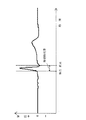
周囲のスポット電極5A、5B、5C、5Dからの距離Sa、Sb、Sc、Sdが演算されると、演算回路2は、各々のスポット電極5A、5B、5C、5Dの心電位から前述の(1)の式で特定位置の心電位Vpを演算する。所定のサンプリング周期で検出された心電位が演算されて、時間を関数とする心電波形が演算される。演算された心電波形は、外部出力装置6に表示される。心電波形は、図19に示すように、横軸を時間、縦軸を電圧として表示される。When the distances Sa, Sb, Sc, and Sd from the surrounding spot electrodes 5A, 5B, 5C, and 5D are calculated, the arithmetic circuit 2 calculates the above-described (( The electrocardiogram Vp at a specific position is calculated using the equation 1). An electrocardiogram detected at a predetermined sampling period is calculated, and an electrocardiogram waveform as a function of time is calculated. The computed electrocardiogram waveform is displayed on the external output device 6. As shown in FIG. 19, the electrocardiogram waveform is displayed with time on the horizontal axis and voltage on the vertical axis.

さらに、本発明の体表面心電計は、図20に示すように、入力装置7で複数点の特定位置を指定して、これらの特定位置の心電波形を外部出力装置6に表示することもできる。この図に示すモニタ6Aは、画面の左側部分に、心電位検出体表面領域Aにおけるスポット電極5の位置と、演算回路2で演算された体表面電位分布図の両方を表示し、画面の右側部分に入力装置で指定した複数点の心電波形を表示している。この図では、体表面電位分布図上において、P1〜P6で示す6点の特定位置を指定している。モニタ6Aには、各特定位置における心電波形であって、演算回路で演算された心電波形を表示している。各特定位置に対応する心電波形は、横軸を時間、縦軸を電圧として、同期して表示している。この図では、6点の特定位置を指定して6個の心電波形を表示しているが、特定位置は2〜5点あるいは7点以上とすることもできる。このように、複数点の特定位置を指定して心電波形を表示する体表面心電計は、従来から多く使用されている12誘導心電計の測定ポイントと同じ位置を特定位置に指定して心電波形を表示することにより、従来の12誘導心電計での診断データを参考にしながら診断できる特長がある。  Furthermore, as shown in FIG. 20, the body surface electrocardiograph of the present invention designates a plurality of specific positions with the input device 7 and displays the electrocardiographic waveforms at these specific positions on the external output device 6. You can also. The monitor 6A shown in this figure displays both the position of the spot electrode 5 in the electrocardiogram detection body surface region A and the body surface potential distribution map calculated by the arithmetic circuit 2 on the left side of the screen, and the right side of the screen. A plurality of ECG waveforms specified by the input device are displayed in the area. In this figure, six specific positions indicated by P1 to P6 are designated on the body surface potential distribution diagram. On the monitor 6A, an electrocardiogram waveform at each specific position and displayed by the arithmetic circuit is displayed. The electrocardiographic waveform corresponding to each specific position is displayed in synchronization with time on the horizontal axis and voltage on the vertical axis. In this figure, six specific electrocardiographic waveforms are displayed by designating six specific positions, but the specific positions may be 2 to 5 points or 7 points or more. As described above, the body surface electrocardiograph that displays the electrocardiogram waveform by designating a plurality of specific positions designates the same position as the measurement position of the 12-lead electrocardiograph that has been conventionally used as the specific position. By displaying the electrocardiogram waveform, there is a feature that diagnosis can be performed with reference to diagnostic data obtained by a conventional 12-lead electrocardiograph.

さらに、本発明の体表面心電計は、モニタ6Aに表示した心電波形を元にして、特定時間における体表面電位分布図を外部出力装置6に表示することもできる。この体表面心電計は、モニタ6Aに表示された心電波形を見ながら、体表面電位分布図を表示したい特定時間を指定し、その特定時間における体表面電位分布図をモニタ6Aに表示する。特定時間は入力装置7を操作して入力される。特定時間は、心電波形が表示されたモニタ6Aの画面上でカーソルを移動させて指定される。特定時間は、たとえば、図19に示すように、時間軸である横軸に垂直な直線を時間軸方向に移動させて指定できる。ただ、特定時間は、心電波形の特定の位置をマーキングして指定することも、時間軸の目盛りを読み取って数値で入力することもできる。演算回路2は、入力装置7で指定された特定時間を読み取り、この時間における体表面電位分布図を記憶媒体から呼び出してモニタ6Aに表示する。  Furthermore, the body surface electrocardiograph of the present invention can also display on the external output device 6 a body surface potential distribution diagram at a specific time based on the electrocardiogram waveform displayed on the monitor 6A. This body surface electrocardiograph designates a specific time for displaying a body surface potential distribution map while viewing the electrocardiogram waveform displayed on the monitor 6A, and displays the body surface potential distribution map at the specific time on the monitor 6A. . The specific time is input by operating the input device 7. The specific time is specified by moving the cursor on the screen of the monitor 6A on which the electrocardiogram waveform is displayed. For example, as shown in FIG. 19, the specific time can be specified by moving a straight line perpendicular to the horizontal axis, which is the time axis, in the time axis direction. However, the specific time can be specified by marking a specific position of the electrocardiogram waveform, or can be input numerically by reading the scale on the time axis. The arithmetic circuit 2 reads the specific time designated by the input device 7, calls the body surface potential distribution diagram at this time from the storage medium, and displays it on the monitor 6A.

さらに、本発明の体表面心電計は、モニタ6Aに表示した心電波形を元にして、特定の時間帯である連続表示時間帯における体表面電位分布図の変化を表示することもできる。この体表面心電計は、モニタ6Aに表示された心電波形を見ながら、体表面電位分布図を表示したい連続表示時間帯を指定し、特定した連続表示時間帯における体表面電位分布図の変化をモニタ6Aに表示する。連続表示時間帯は入力装置7を操作して入力される。連続表示時間帯は、心電波形が表示されたモニタ6Aの画面上でカーソルを移動させて、その始点と終点の2ヶ所を指定して特定される。連続表示時間帯の始点と終点は、たとえば、図21に示すように、時間軸である横軸に垂直な直線を時間軸方向に移動させて指定できる。ただ、連続表示時間帯は、直線でなく枠を表示して特定することも、時間軸の目盛りを読み取って数値で入力して特定することもできる。演算回路2は、入力装置7で指定された連続表示時間帯を読み取り、この時間帯における体表面電位分布図を記憶媒体から呼び出してモニタ6Aに表示する。体表面電位分布図は、図22に示すように、所定の時間間隔Tで切り換えられて連続的に繰り返し表示される。  Furthermore, the body surface electrocardiograph of the present invention can also display changes in the body surface potential distribution diagram in a continuous display time zone, which is a specific time zone, based on the electrocardiographic waveform displayed on the monitor 6A. This body surface electrocardiograph specifies a continuous display time zone in which a body surface potential distribution map is to be displayed while observing the electrocardiogram waveform displayed on the monitor 6A, and the body surface potential distribution map in the specified continuous display time zone. The change is displayed on the monitor 6A. The continuous display time zone is input by operating the input device 7. The continuous display time zone is specified by moving the cursor on the screen of the monitor 6A on which the electrocardiogram waveform is displayed, and specifying the two start points and end points. For example, as shown in FIG. 21, the start point and the end point of the continuous display time zone can be specified by moving a straight line perpendicular to the horizontal axis, which is the time axis, in the time axis direction. However, the continuous display time zone can be specified by displaying a frame instead of a straight line, or can be specified by reading a scale on the time axis and inputting a numerical value. The arithmetic circuit 2 reads the continuous display time zone designated by the input device 7, calls up the body surface potential distribution map in this time zone from the storage medium, and displays it on the monitor 6A. As shown in FIG. 22, the body surface potential distribution map is switched at a predetermined time interval T and displayed continuously and repeatedly.

本発明の体表面心電計の使用方法を以下に示す。
演算回路2は、以下のようにして体表面電位分布図を作成する。使用者が体表面電位分布図を得たい時間間隔を入力装置7から演算回路2に入力する。演算回路2は、入力された時間間隔に従い、その時間毎にスポット電極5から体表面各点での心電位を測定する。測定された電位値は記憶されて、演算回路2に送られ、演算回路2で演算されて等電位線が算出される。演算回路2は、手足に接続している不関電極8に誘導される電位を基準電圧として心電圧を演算し、等電位線を算出する。このデータが外部出力装置6に送られ、体表面電位分布図が表示される。この操作が、入力された時間毎に繰り返され、使用者は時間毎に切り換わる体表面電位分布図を観測できる。演算回路2は、各時間毎の体表面電位分布図の表示に必要なデータを記憶媒体に保持する。
The method for using the body surface electrocardiograph of the present invention will be described below.
The arithmetic circuit 2 creates a body surface potential distribution diagram as follows. A user inputs a time interval for obtaining a body surface potential distribution map from the input device 7 to the arithmetic circuit 2. The arithmetic circuit 2 measures the electrocardiogram at each point on the body surface from the spot electrode 5 at every time according to the input time interval. The measured potential value is stored and sent to the arithmetic circuit 2, and the arithmetic circuit 2 calculates the equipotential line. The arithmetic circuit 2 calculates a cardiac voltage by using a potential induced in the indifferent electrode 8 connected to the limb as a reference voltage, and calculates an equipotential line. This data is sent to the external output device 6, and a body surface potential distribution map is displayed. This operation is repeated for each input time, and the user can observe a body surface potential distribution map that switches every time. The arithmetic circuit 2 holds data necessary for displaying a body surface potential distribution map for each time in a storage medium.

使用者が、過去のある時点での体表面電位分布図を見たい場合は、入力装置7から演算回路2に所望の時間を入力する。演算回路2は、記憶媒体に保存されたデータの中から所望の時間のデータを呼び出し、このデータに基づき体表面電位分布図を外部出力装置6に表示する。  When the user wants to see a body surface potential distribution diagram at a certain point in the past, the user inputs a desired time to the arithmetic circuit 2 from the input device 7. The arithmetic circuit 2 calls out data at a desired time from the data stored in the storage medium, and displays a body surface potential distribution map on the external output device 6 based on this data.

さらに、使用者が時間の経過順とは逆に、すなわち過去に遡って体表面電位分布図を順に見たい場合は、図22の鎖線の矢印で示すように、演算回路2が、記憶媒体に保持したデータを時間経過とは逆順に、次々と切り換えて外部出力装置6に表示していく。図においてTは、体表面電位分布図の表示を切り換える時間間隔であり、使用者は所望の値を指定できる。  Further, when the user wants to view the body surface potential distribution diagram in reverse order of time, that is, to go back to the past, the arithmetic circuit 2 is connected to the storage medium as shown by the chain line arrow in FIG. The retained data is sequentially displayed in the reverse order to the elapsed time and displayed on the external output device 6. In the figure, T is a time interval for switching the display of the body surface potential distribution map, and the user can specify a desired value.


本発明の体表面心電計は、心電位を検出する時間を20μ秒〜2ミリ秒、好ましくは、50μ秒〜500μ秒とすることができる。体表面心電計は、例えば、100μ秒で心電位をサンプリングした場合、対応する体表面電位分布図は1秒で10000枚が生成される。この体表面電位分布図をそのまま1秒に10000枚表示する必要はなく、使用者は表示する時間間隔Tについて、任意に指定できる。

In the body surface electrocardiograph of the present invention, the time for detecting the cardiac potential can be set to 20 μs to 2 milliseconds, preferably 50 μs to 500 μs. For example, when the body surface electrocardiograph samples the cardiac potential in 100 μs, 10,000 corresponding body surface potential distribution diagrams are generated in one second. There is no need to display 10,000 body surface potential distribution charts per second as they are, and the user can arbitrarily specify the time interval T to be displayed.

例えば、100μ秒おきに測定した体表面電位分布図を、それぞれT=0.2秒で切り替えて過去に向かって表示したい場合、使用者は入力装置7を操作して必要な情報を演算回路2に入力すれば、演算回路2は指令に従い各データを呼び出し、演算し、表示することができる。各時点での体表面電位分布図を連続的に切り換えて表示することで、使用者は時間の経過とともに変動していく心電位の状態を感覚的に把握できる。  For example, when the body surface potential distribution diagram measured every 100 μs is switched at T = 0.2 seconds and displayed toward the past, the user operates the input device 7 to obtain necessary information. , The arithmetic circuit 2 can call up, calculate and display each data according to the command. By continuously switching and displaying the body surface potential distribution chart at each time point, the user can sensuously grasp the state of the cardiac potential that varies with the passage of time.

同様に、例えば100μ秒毎に測定したデータのうち、1ミリ秒おきのデータのみを0.2秒ずつ連続して表示するよう命令することもできる。この場合、検出されたデータのうち、表示されるのは1/10となるので、表示時間を1/10に短縮できる。また、使用者が連続的な表示を中断してある時点の体表面電位分布図を表示し続けたい場合は、入力装置7を操作して、演算回路2に処理の中止を命令すればよい。もちろん、同様の手順によって体表面電位分布図を時間経過順に表示することもできる。また予め体表面電位分布図を測定する時間間隔を短く設定することで、より詳細に変化の状態を表示できることはいうまでもない。このように、使用者は必要な体表面電位分布図をサーチしたり一時停止したりして、より便利かつ詳細に心電位を検討、評価することができる。  Similarly, for example, it is possible to instruct to display only data every 1 millisecond continuously every 0.2 seconds out of data measured every 100 microseconds. In this case, since the detected data is displayed at 1/10, the display time can be reduced to 1/10. If the user wants to continue displaying the body surface potential distribution chart at a point in time when continuous display is interrupted, the input device 7 may be operated to instruct the arithmetic circuit 2 to stop processing. Of course, the body surface potential distribution map can be displayed in the order of time passage by the same procedure. It goes without saying that the state of change can be displayed in more detail by setting the time interval for measuring the body surface potential distribution map in advance. As described above, the user can search and pause the necessary body surface potential distribution map to examine and evaluate the cardiac potential more conveniently and in detail.

特に、心臓の状態は、心臓が鼓動する前後において大きく変化するが、それ以外の時間では変化が穏やかであって、電位分布もそれほど変化しない。さらに、変化の大きい部分の体表面電位分布図は、心臓が正常な者と疾患を有する者とで異なる。したがって、心臓の状態を調べるには、変化がピークとなる心鼓動の前後の期間を集中して分析することが重要である。逆に言うと、それ以外のデータはスキップすることができる。  In particular, the state of the heart changes greatly before and after the heart beats, but the change is gentle at other times and the potential distribution does not change much. Furthermore, the body surface potential distribution map of the portion with the large change is different between the normal heart and the diseased person. Therefore, in order to examine the state of the heart, it is important to concentrate and analyze the period before and after the heartbeat when the change peaks. Conversely, other data can be skipped.

例えばT=0.2秒、すなわち1秒毎に5画面を一定間隔で表示すれば、1秒間に取得した心電データを表示するのに要する時間は2000秒となり、約33分である。この場合で、心臓が1秒に1回鼓動するとして、変化のピーク期間を0.2秒とすれば、この期間の体表面電位分布図を表示するのに要する時間は約7分となる。さらに、T=0.1秒、すなわち1秒毎に10画面を表示すれば、1秒間に取得した心電データを表示するのに要する時間は1000秒(約17分)となり、変化のピーク期間を0.2秒とすれば、この期間の体表面電位分布図を表示するのに要する時間は200秒(約3分)となる。したがって、使用者は表示画面を確認しながら表示時間Tを変更して、不要と思われる部分ではTを短くして時間を短縮でき、さらに必要と思われる部分ではTを長くして分布図を詳細に検討することができ、極めて効率よく心電位を検索し、分析することができる。1画面を表示する時間である表示時間Tは、0.01秒〜1秒、好ましくは0.05秒〜0.5秒とすることができる。さらに、心電データを取り出す、変化のピーク期間は、0.05〜1秒、好ましくは0.1〜0.8秒とすることができる。  For example, if 5 screens are displayed at regular intervals at T = 0.2 seconds, that is, every second, the time required to display the electrocardiographic data acquired per second is 2000 seconds, which is about 33 minutes. In this case, assuming that the heart beats once per second and the peak period of change is 0.2 seconds, the time required to display the body surface potential distribution map during this period is about 7 minutes. Furthermore, T = 0.1 seconds, that is, if 10 screens are displayed every second, the time required to display the electrocardiogram data acquired per second is 1000 seconds (about 17 minutes), and the peak period of change Is 0.2 seconds, the time required to display the body surface potential distribution map during this period is 200 seconds (about 3 minutes). Therefore, the user can change the display time T while confirming the display screen, and shorten the time by shortening T in the part that seems unnecessary, and lengthen T in the part that seems to be necessary, and draw the distribution map. It is possible to examine in detail and to search and analyze the cardiac potential very efficiently. The display time T, which is the time for displaying one screen, can be 0.01 seconds to 1 second, preferably 0.05 seconds to 0.5 seconds. Furthermore, the peak period of change in which the electrocardiographic data is taken out can be 0.05 to 1 second, preferably 0.1 to 0.8 second.

このように体表面電位分布図を表示する方法は、あたかもビデオテープレコーダを使用してビデオテープに記録された画像を再生する際に、逆再生、順再生、スロー再生、コマ送り、早送り、巻き戻し等、再生方法を自由に指定できることに近似している。つまり、各画面に相当する体表面電位分布図のデータを記憶、保持しておき、これを所定の方法で順次表示することによって、連続的に変化していく電位分布の変動の様子を使用者は自由にサーチ、モニタできるので、簡単かつ正確に状況を把握することができる。  Thus, the method of displaying the body surface potential distribution map is as if playing back an image recorded on a video tape using a video tape recorder, reverse playback, forward playback, slow playback, frame advance, fast forward, winding. It approximates that the playback method can be freely specified, such as return. In other words, the body surface potential distribution map data corresponding to each screen is stored and retained, and this is sequentially displayed by a predetermined method, so that the variation of the potential distribution that changes continuously is displayed to the user. Can search and monitor freely, so you can grasp the situation easily and accurately.

さらに、特定位置の心電波形を得たいときは、入力装置7を操作して、図17に示すように、モニタ6Aに表示された心電位検出体表面領域あるいは体表面電位分布図上で特定位置を指定する。演算回路2は、特定位置の心電位を演算して、時間に対する心電波形を演算する。演算回路2で演算された特定位置の心電波形は、外部出力装置6に表示される。  Furthermore, when it is desired to obtain an electrocardiogram waveform at a specific position, the input device 7 is operated to specify the electrocardiogram detection body surface area or body surface potential distribution map displayed on the monitor 6A as shown in FIG. Specify the position. The arithmetic circuit 2 calculates an electrocardiogram at a specific position and calculates an electrocardiographic waveform with respect to time. The electrocardiographic waveform at a specific position calculated by the arithmetic circuit 2 is displayed on the external output device 6.

さらに、特定位置の心電波形を元にして、特定時間における体表面電位分布図を得たいときには、入力装置7を操作して、図19に示すように、心電波形を見ながら特定時間を指定する。演算回路2は、入力装置7で指定された特定時間における体表面電位分布図を演算回路2で演算して外部出力装置6に表示する。  Further, when it is desired to obtain a body surface potential distribution map at a specific time based on the electrocardiogram waveform at a specific position, the input device 7 is operated to set the specific time while looking at the electrocardiogram waveform as shown in FIG. specify. The arithmetic circuit 2 calculates a body surface potential distribution diagram at a specific time designated by the input device 7 by the arithmetic circuit 2 and displays it on the external output device 6.

さらにまた、特定位置の心電波形を元にして、連続表示時間帯における体表面電位分布図の変化を得たいときには、入力装置7を操作して、図21に示すように心電波形を見ながら連続表示時間帯を指定する。演算回路2は、入力装置7で指定された連続表示時間帯における体表面電位分布図を演算回路2で演算して外部出力装置6に表示する。すなわち、演算回路2は、連続表示時間帯における体表面電位分布図の変化を、外部出力装置6に繰り返し表示する。指定された連続表示時間帯における体表面電位分布図の変化は、時間経過順に表示し、あるいは時間経過とは逆に表示することができる。さらに、連続表示時間帯における体表面電位分布図の変化は、スロー表示、コマ送り表示、早送り表示、巻き戻し表示等、表示方法を変更しながら表示することができる。  Furthermore, when it is desired to obtain a change in the body surface potential distribution diagram in the continuous display time zone based on the electrocardiogram waveform at a specific position, the input device 7 is operated to view the electrocardiogram waveform as shown in FIG. Specify the continuous display time zone. The arithmetic circuit 2 calculates the body surface potential distribution diagram in the continuous display time zone designated by the input device 7 by the arithmetic circuit 2 and displays it on the external output device 6. That is, the arithmetic circuit 2 repeatedly displays changes in the body surface potential distribution diagram in the continuous display time zone on the external output device 6. Changes in the body surface potential distribution diagram in the designated continuous display time zone can be displayed in the order of time passage, or can be displayed opposite to the time passage. Furthermore, changes in the body surface potential distribution diagram during the continuous display time period can be displayed while changing the display method, such as slow display, frame advance display, fast forward display, and rewind display.

心臓付近の体表面の体表面電位分布図Body surface potential distribution map of the body surface near the heart 本発明の一実施例にかかる体表面心電計のブロック線図1 is a block diagram of a body surface electrocardiograph according to one embodiment of the present invention. 本発明の一実施例にかかる体表面心電計の電極システムの概略斜視図1 is a schematic perspective view of an electrode system of a body surface electrocardiograph according to an embodiment of the present invention. 図3に示す電極システムの使用状態を示す概略横断面図Schematic cross-sectional view showing the state of use of the electrode system shown in FIG. 心電位検出体表面領域を示す概略斜視図Schematic perspective view showing the surface area of the electrocardiogram detector 図3に示す電極システムの上側電極であるロッド電極の正面図The front view of the rod electrode which is an upper electrode of the electrode system shown in FIG. 図6に示すロッド電極の底面図Bottom view of rod electrode shown in FIG. ロッド電極の電極ユニットの斜視図Perspective view of electrode unit of rod electrode 図8に示す電極ユニットの断面図Sectional view of the electrode unit shown in FIG. 図9に示す電極ユニットの上方の板材の底面図Bottom view of plate material above electrode unit shown in FIG. 図3に示す電極システムの下側電極であるクッション電極の斜視図The perspective view of the cushion electrode which is a lower electrode of the electrode system shown in FIG. 図11に示す下側電極の拡大断面図11 is an enlarged sectional view of the lower electrode shown in FIG. 図3に示す電極システムの体側電極であるクッション電極の垂直断面図The vertical sectional view of the cushion electrode which is a body side electrode of the electrode system shown in FIG. 局部電極の拡大断面図Expanded cross section of local electrode 図3に示す電極システムの使用状態を示す概略平面図The schematic plan view which shows the use condition of the electrode system shown in FIG. 演算回路が特定位置の心電位を演算する方法を示す概略図Schematic showing how the arithmetic circuit calculates the cardiac potential at a specific position モニタに表示される心電位検出体表面領域と体表面電位分布図を示す図The figure which shows the cardiac potential detection body surface area and body surface potential distribution map which are displayed on the monitor モニタに表示される心電位検出体表面領域と各スポット電極における心電波形を示す図The figure which shows the electrocardiogram waveform in each electrocardiogram detection body surface area and each spot electrode displayed on a monitor 特定位置における心電波形の一例を示す図であって特定時間を指定する状態を示す図The figure which shows an example of the electrocardiogram waveform in a specific position, Comprising: The figure which shows the state which designates specific time モニタに表示される心電位検出体表面領域で複数の特定位置を指定して複数の心電波形を表示する状態を示す図The figure which shows the state which designates several specific positions in the electrocardiogram detection body surface area displayed on a monitor, and displays several electrocardiogram waveforms 特定位置における心電波形の一例を示す図であって連続表示時間帯を指定する状態を示す図The figure which shows an example of the electrocardiogram waveform in a specific position, Comprising: The figure which shows the state which designates a continuous display time slot | zone 体表面電位分布図の表示方法の一例を示す概念図Conceptual diagram showing an example of a method for displaying a body surface potential distribution map

1…電極システム 1A…上側電極 1B…下側電極
1C…体側電極
2…演算回路
3…ベッド
4…吊下機構 4A…上下台 4B…支持台
5…スポット電極
6…外部出力装置 6A…モニタ 6B…プリンター
7…入力装置
8…不関電極
9…アース電極
10…ロッド電極
11…電極ユニット
12…導電ロッド 12A…接触電極 12B…ロッド部
12a…接触面
13…電極本体
14…コイルスプリング
15…可動性部材
16…弾性変形プレート
18…吊り紐
20…クッション電極
21…可撓性シート
22…局部電極 22A…接触電極 22B…固定部
23…弾性押圧材 23A…弾性変形プレート
24…接触面
25…連結凸部 25A…筒部 25B…鍔
26…貫通孔
27…リード線
28…接着剤
30…押出スプリング
31…固定ケース
32…周壁
33…支持プレート
34…昇降機構
35…スライド機構
36…位置決ライン
40…装着バンド
41…連結具
50…ケース
51…板材 51A…挿通孔
52…支柱
53…ガイドプレート 53A…ガイド孔
54…導電層
55…固定リング
57…リード線
60…引出線
61…リード線
DESCRIPTION OF SYMBOLS 1 ... Electrode system 1A ... Upper electrode 1B ... Lower electrode
DESCRIPTION OF SYMBOLS 1C ... Body side electrode 2 ... Arithmetic circuit 3 ... Bed 4 ... Suspension mechanism 4A ... Upper / lower stand 4B ... Support stand 5 ... Spot electrode 6 ... External output device 6A ... Monitor 6B ... Printer 7 ... Input device 8 ... Indifferent electrode 9 ... Earth electrode 10 ... Rod electrode 11 ... Electrode unit 12 ... Conductive rod 12A ... Contact electrode 12B ... Rod part
12a ... Contact surface 13 ... Electrode body 14 ... Coil spring 15 ... Movable member 16 ... Elastic deformation plate 18 ... Hanging string 20 ... Cushion electrode 21 ... Flexible sheet 22 ... Local electrode 22A ... Contact electrode 22B ... Fixed part 23 ... Elastic pressing material 23A ... Elastic deformation plate 24 ... Contact surface 25 ... Connection convex part 25A ... Cylindrical part 25B ... Rod 26 ... Through-hole 27 ... Lead wire 28 ... Adhesive 30 ... Extrusion spring 31 ... Fixed case 32 ... Peripheral wall 33 ... Support Plate 34 ... Elevating mechanism 35 ... Slide mechanism 36 ... Positioning line 40 ... Mounting band 41 ... Connecting tool 50 ... Case 51 ... Plate material 51A ... Insertion hole 52 ... Post 53 ... Guide plate 53A ... Guide hole 54 ... Conductive layer 55 ... Fixed Ring 57 ... Lead wire 60 ... Lead wire 61 ... Lead wire

Claims (6)

体内側に心臓を配置している心電位検出体表面領域(A)の複数点に接触して、体表面に誘導される心電位を検出する複数のスポット電極(5)を備える電極システム(1)と、電極システム(1)の各々のスポット電極(5)に誘導される心電圧を演算して体表面に誘導される体表面電位分布図を演算する演算回路(2)と、この演算回路(2)で演算された体表面電位分布図を表示する外部出力装置(6)を備える体表面心電計であって、
演算回路(2)に、心電位検出体表面領域(A)であってスポット電極(5)の間に位置する特定位置を指定できる入力装置(7)を接続しており、演算回路(2)が、入力装置(7)で指定された特定位置の時間に対する心電位の変化である心電波形を、特定位置の近傍に位置する複数のスポット電極(5)に誘導される心電位から演算し、演算した特定位置の心電波形を、横軸を時間、縦軸を電圧とする心電波形として外部出力装置(6)で表示するようにしてなる体表面心電計。
Electrode system (1) comprising a plurality of spot electrodes (5) for detecting a cardiac potential induced on the body surface in contact with a plurality of points on the surface area (A) of the body potential detection body surface (A) in which the heart is placed inside the body ), An arithmetic circuit (2) for calculating a cardiac surface voltage distribution diagram induced on the body surface by calculating a cardiac voltage induced to each spot electrode (5) of the electrode system (1), and this arithmetic circuit A body surface electrocardiograph comprising an external output device (6) for displaying the body surface potential distribution diagram calculated in (2),
The arithmetic circuit (2) is connected to an input device (7) that can specify a specific position located between the spot electrodes (5) on the surface area (A) of the electrocardiogram detection body. Is calculated from the electrocardiograms induced by a plurality of spot electrodes (5) located in the vicinity of the specific position. The body surface electrocardiograph configured to display the computed electrocardiographic waveform at a specific position on the external output device (6) as an electrocardiographic waveform with the horizontal axis representing time and the vertical axis representing voltage .
入力装置(7)がマウスである請求項1に記載される体表面心電計。  The body surface electrocardiograph according to claim 1, wherein the input device (7) is a mouse. 心電位検出体表面領域(A)に接触するスポット電極(5)の個数が100〜1000個である請求項1に記載される体表面心電計。  The body surface electrocardiograph according to claim 1, wherein the number of spot electrodes (5) in contact with the electrocardiographic potential detection body surface region (A) is 100 to 1000. 演算回路(2)が、手足に接続している不関電極(8)に誘導される電位を基準電圧として、心電位の時間に対する変化を演算する請求項1に記載される体表面心電計。  2. The body surface electrocardiograph according to claim 1, wherein the arithmetic circuit (2) calculates a change of the cardiac potential with respect to time using the potential induced in the indifferent electrode (8) connected to the limb as a reference voltage. . 外部出力装置(6)が、体表面電位分布図と心電波形を表示するモニタ(6A)を備えており、モニタ(6A)に表示される心電波形で特定の時間を特定し、特定時間における体表面電位分布図を演算回路(2)で演算してモニタ(6A)に表示するようにしてなる請求項1に記載される体表面心電計。  The external output device (6) is equipped with a monitor (6A) that displays the body surface potential distribution map and the electrocardiogram waveform. The electrocardiogram waveform displayed on the monitor (6A) identifies a specific time, and the specific time The body surface electrocardiograph according to claim 1, wherein the body surface potential distribution diagram is calculated by the arithmetic circuit (2) and displayed on the monitor (6A). 外部出力装置(6)が、体表面電位分布図と心電波形を表示するモニタ(6A)を備えており、モニタ(6A)に表示される心電波形で連続表示時間帯を特定し、連続表示時間帯における体表面電位分布図を演算回路(2)で演算してモニタ(6A)に繰り返し表示するようにしてなる請求項1に記載される体表面心電計。  The external output device (6) is equipped with a monitor (6A) that displays the body surface potential distribution map and the electrocardiogram waveform, and identifies the continuous display time zone by the electrocardiogram waveform displayed on the monitor (6A), The body surface electrocardiograph according to claim 1, wherein a body surface potential distribution diagram in a display time zone is calculated by a calculation circuit (2) and repeatedly displayed on a monitor (6A).
JP2004108555A 2004-03-31 2004-03-31 Body surface electrocardiograph Expired - Fee Related JP4630397B2 (en)

Priority Applications (1)

Application Number Priority Date Filing Date Title
JP2004108555A JP4630397B2 (en) 2004-03-31 2004-03-31 Body surface electrocardiograph

Applications Claiming Priority (1)

Application Number Priority Date Filing Date Title
JP2004108555A JP4630397B2 (en) 2004-03-31 2004-03-31 Body surface electrocardiograph

Publications (2)

Publication Number Publication Date
JP2005287849A JP2005287849A (en) 2005-10-20
JP4630397B2 true JP4630397B2 (en) 2011-02-09

Family

ID=35321450

Family Applications (1)

Application Number Title Priority Date Filing Date
JP2004108555A Expired - Fee Related JP4630397B2 (en) 2004-03-31 2004-03-31 Body surface electrocardiograph

Country Status (1)

Country Link
JP (1) JP4630397B2 (en)

Cited By (1)

* Cited by examiner, † Cited by third party
Publication number Priority date Publication date Assignee Title
KR101626855B1 (en) * 2014-12-16 2016-06-02 금오공과대학교 산학협력단 device and method for diagnosing cardiac arrhythmia using body surface potential mapping

Families Citing this family (3)

* Cited by examiner, † Cited by third party
Publication number Priority date Publication date Assignee Title
JP4683423B2 (en) * 2006-01-19 2011-05-18 国立大学法人徳島大学 Body surface electrocardiograph
JP6628074B2 (en) 2014-06-30 2020-01-08 パナソニックIpマネジメント株式会社 Cardiac potential measuring device and cardiac potential measuring method
JP7297464B2 (en) 2019-02-22 2023-06-26 フクダ電子株式会社 BIOLOGICAL SIGNAL PROCESSING DEVICE AND DATA GENERATION METHOD FOR AUTOMATIC ANALYSIS

Citations (3)

* Cited by examiner, † Cited by third party
Publication number Priority date Publication date Assignee Title
JP2001510356A (en) * 1996-07-17 2001-07-31 ケンブリッジ・ハート・インコーポレイテッド Generating local heart metrics
JP2002224069A (en) * 2001-02-07 2002-08-13 Japan Science & Technology Corp Body surface multi-lead electrocardiogram device and analytical method using this device
JP3330597B2 (en) * 1990-10-26 2002-09-30 マサチューセッツ・インステチュート・オブ・テクノロジー Method and apparatus for imaging electrical activity in biological systems

Family Cites Families (9)

* Cited by examiner, † Cited by third party
Publication number Priority date Publication date Assignee Title
JPS5558154A (en) * 1978-10-24 1980-04-30 Toshimitsu Mushiya Electronic diagnosis device
JPS55130650A (en) * 1979-04-02 1980-10-09 Toshimitsu Mushiya Device for recording distribution data of electric potential on surface of body
JPS55130651A (en) * 1979-04-02 1980-10-09 Toshimitsu Mushiya Device for displaying distribution of electric potential on surface of body
JPS56119230A (en) * 1980-02-22 1981-09-18 Norio Akamatsu Electrocardiogram
JPS58165822A (en) * 1982-03-27 1983-09-30 赤松 則男 Electrocardiograph
JPS6156632A (en) * 1984-08-24 1986-03-22 臼井 支朗 Method for confirming wave form of electrocardiograph and display of body surface electrocardiograph using the same
JPH0245036A (en) * 1988-08-04 1990-02-15 Kawabe Jiro Method for measuring organism potential
DE19622078A1 (en) * 1996-05-31 1997-12-04 Siemens Ag Active current localising appts. for heart
JP3771696B2 (en) * 1997-10-09 2006-04-26 阿波エンジニアリング株式会社 Body surface electrocardiograph and body surface potential distribution map display method

Patent Citations (3)

* Cited by examiner, † Cited by third party
Publication number Priority date Publication date Assignee Title
JP3330597B2 (en) * 1990-10-26 2002-09-30 マサチューセッツ・インステチュート・オブ・テクノロジー Method and apparatus for imaging electrical activity in biological systems
JP2001510356A (en) * 1996-07-17 2001-07-31 ケンブリッジ・ハート・インコーポレイテッド Generating local heart metrics
JP2002224069A (en) * 2001-02-07 2002-08-13 Japan Science & Technology Corp Body surface multi-lead electrocardiogram device and analytical method using this device

Cited By (1)

* Cited by examiner, † Cited by third party
Publication number Priority date Publication date Assignee Title
KR101626855B1 (en) * 2014-12-16 2016-06-02 금오공과대학교 산학협력단 device and method for diagnosing cardiac arrhythmia using body surface potential mapping

Also Published As

Publication number Publication date
JP2005287849A (en) 2005-10-20

Similar Documents

Publication Publication Date Title
JP4208862B2 (en) Integrated multi-electrode for biosignal measurement, bio-signal measurement method and apparatus using integrated multi-electrode, and lead search method using integrated multi-electrode
US7409242B2 (en) Active muscle display device
RU2720668C2 (en) Apparatus and method for determining and/or monitoring an individual&#39;s respiratory effort
CN103429148B (en) The system that electrical activity figure is provided is sensed for using optic shape
KR20170058363A (en) Contactless electric cardiogram system
KR20120003662A (en) Apparatus and method for measuring biological signal
JP2007195690A (en) Portable electrocardiographic device
KR20170067131A (en) Blood presure measurement apparatus and blood presure measuring method using the same
WO2018047788A1 (en) Blood pressure measurement device, method for controlling blood pressure measurement device, and program
CA3119565A1 (en) Multi-sensor resistive textile ecg system
KR101843083B1 (en) Apparatus and method for measuring biological including multiple unit measurer
JP4630397B2 (en) Body surface electrocardiograph
JP4683423B2 (en) Body surface electrocardiograph
JP4272703B2 (en) Body surface electrocardiograph
US11109787B2 (en) Multi-tip probe for obtaining bioelectrical measurements
US10433745B1 (en) Handheld ECG monitoring system with fault detection
US20230301578A1 (en) Device And Method Of Monitoring Mental State And Jaw Movements
JPH0246209B2 (en)
US20100152602A1 (en) Whole body electromagnetic detection system
JP3771696B2 (en) Body surface electrocardiograph and body surface potential distribution map display method
JP4065192B2 (en) Body surface electrocardiograph
JP2019010436A (en) Biological sensor and signal acquisition method of biological sensor
JP2004166934A (en) Body surface electrocardiograph
JP2004187736A (en) Body surface electrocardiograph
JPS58165822A (en) Electrocardiograph

Legal Events

Date Code Title Description
A621 Written request for application examination

Free format text: JAPANESE INTERMEDIATE CODE: A621

Effective date: 20070319

A977 Report on retrieval

Free format text: JAPANESE INTERMEDIATE CODE: A971007

Effective date: 20100402

A131 Notification of reasons for refusal

Free format text: JAPANESE INTERMEDIATE CODE: A131

Effective date: 20100427

A521 Request for written amendment filed

Free format text: JAPANESE INTERMEDIATE CODE: A523

Effective date: 20100628

TRDD Decision of grant or rejection written
A01 Written decision to grant a patent or to grant a registration (utility model)

Free format text: JAPANESE INTERMEDIATE CODE: A01

Effective date: 20101109

A01 Written decision to grant a patent or to grant a registration (utility model)

Free format text: JAPANESE INTERMEDIATE CODE: A01

A61 First payment of annual fees (during grant procedure)

Free format text: JAPANESE INTERMEDIATE CODE: A61

Effective date: 20101113

FPAY Renewal fee payment (event date is renewal date of database)

Free format text: PAYMENT UNTIL: 20131119

Year of fee payment: 3

R150 Certificate of patent or registration of utility model

Ref document number: 4630397

Country of ref document: JP

Free format text: JAPANESE INTERMEDIATE CODE: R150

Free format text: JAPANESE INTERMEDIATE CODE: R150

R250 Receipt of annual fees

Free format text: JAPANESE INTERMEDIATE CODE: R250

R250 Receipt of annual fees

Free format text: JAPANESE INTERMEDIATE CODE: R250

R250 Receipt of annual fees

Free format text: JAPANESE INTERMEDIATE CODE: R250

R250 Receipt of annual fees

Free format text: JAPANESE INTERMEDIATE CODE: R250

R250 Receipt of annual fees

Free format text: JAPANESE INTERMEDIATE CODE: R250

R250 Receipt of annual fees

Free format text: JAPANESE INTERMEDIATE CODE: R250

LAPS Cancellation because of no payment of annual fees