JP4625671B2 - Audio signal reproduction method and reproduction apparatus therefor - Google Patents
Audio signal reproduction method and reproduction apparatus therefor Download PDFInfo
- Publication number
- JP4625671B2 JP4625671B2 JP2004297093A JP2004297093A JP4625671B2 JP 4625671 B2 JP4625671 B2 JP 4625671B2 JP 2004297093 A JP2004297093 A JP 2004297093A JP 2004297093 A JP2004297093 A JP 2004297093A JP 4625671 B2 JP4625671 B2 JP 4625671B2
- Authority
- JP
- Japan
- Prior art keywords
- speakers
- transfer function
- audio signal
- speaker array
- sound
- Prior art date
- Legal status (The legal status is an assumption and is not a legal conclusion. Google has not performed a legal analysis and makes no representation as to the accuracy of the status listed.)
- Expired - Fee Related
Links
Images


Classifications
-
- H—ELECTRICITY
- H04—ELECTRIC COMMUNICATION TECHNIQUE
- H04S—STEREOPHONIC SYSTEMS
- H04S1/00—Two-channel systems
-
- H—ELECTRICITY
- H04—ELECTRIC COMMUNICATION TECHNIQUE
- H04R—LOUDSPEAKERS, MICROPHONES, GRAMOPHONE PICK-UPS OR LIKE ACOUSTIC ELECTROMECHANICAL TRANSDUCERS; DEAF-AID SETS; PUBLIC ADDRESS SYSTEMS
- H04R3/00—Circuits for transducers, loudspeakers or microphones
- H04R3/12—Circuits for transducers, loudspeakers or microphones for distributing signals to two or more loudspeakers
-
- G—PHYSICS
- G10—MUSICAL INSTRUMENTS; ACOUSTICS
- G10K—SOUND-PRODUCING DEVICES; METHODS OR DEVICES FOR PROTECTING AGAINST, OR FOR DAMPING, NOISE OR OTHER ACOUSTIC WAVES IN GENERAL; ACOUSTICS NOT OTHERWISE PROVIDED FOR
- G10K15/00—Acoustics not otherwise provided for
-
- G—PHYSICS
- G11—INFORMATION STORAGE
- G11B—INFORMATION STORAGE BASED ON RELATIVE MOVEMENT BETWEEN RECORD CARRIER AND TRANSDUCER
- G11B20/00—Signal processing not specific to the method of recording or reproducing; Circuits therefor
-
- H—ELECTRICITY
- H04—ELECTRIC COMMUNICATION TECHNIQUE
- H04S—STEREOPHONIC SYSTEMS
- H04S7/00—Indicating arrangements; Control arrangements, e.g. balance control
- H04S7/30—Control circuits for electronic adaptation of the sound field
-
- H—ELECTRICITY
- H04—ELECTRIC COMMUNICATION TECHNIQUE
- H04R—LOUDSPEAKERS, MICROPHONES, GRAMOPHONE PICK-UPS OR LIKE ACOUSTIC ELECTROMECHANICAL TRANSDUCERS; DEAF-AID SETS; PUBLIC ADDRESS SYSTEMS
- H04R2201/00—Details of transducers, loudspeakers or microphones covered by H04R1/00 but not provided for in any of its subgroups
- H04R2201/40—Details of arrangements for obtaining desired directional characteristic by combining a number of identical transducers covered by H04R1/40 but not provided for in any of its subgroups
- H04R2201/403—Linear arrays of transducers
-
- H—ELECTRICITY
- H04—ELECTRIC COMMUNICATION TECHNIQUE
- H04R—LOUDSPEAKERS, MICROPHONES, GRAMOPHONE PICK-UPS OR LIKE ACOUSTIC ELECTROMECHANICAL TRANSDUCERS; DEAF-AID SETS; PUBLIC ADDRESS SYSTEMS
- H04R2203/00—Details of circuits for transducers, loudspeakers or microphones covered by H04R3/00 but not provided for in any of its subgroups
- H04R2203/12—Beamforming aspects for stereophonic sound reproduction with loudspeaker arrays
-
- H—ELECTRICITY
- H04—ELECTRIC COMMUNICATION TECHNIQUE
- H04R—LOUDSPEAKERS, MICROPHONES, GRAMOPHONE PICK-UPS OR LIKE ACOUSTIC ELECTROMECHANICAL TRANSDUCERS; DEAF-AID SETS; PUBLIC ADDRESS SYSTEMS
- H04R2430/00—Signal processing covered by H04R, not provided for in its groups
- H04R2430/20—Processing of the output signals of the acoustic transducers of an array for obtaining a desired directivity characteristic
-
- H—ELECTRICITY
- H04—ELECTRIC COMMUNICATION TECHNIQUE
- H04S—STEREOPHONIC SYSTEMS
- H04S2420/00—Techniques used stereophonic systems covered by H04S but not provided for in its groups
- H04S2420/13—Application of wave-field synthesis in stereophonic audio systems
-
- H—ELECTRICITY
- H04—ELECTRIC COMMUNICATION TECHNIQUE
- H04S—STEREOPHONIC SYSTEMS
- H04S3/00—Systems employing more than two channels, e.g. quadraphonic
Landscapes
- Engineering & Computer Science (AREA)
- Physics & Mathematics (AREA)
- Acoustics & Sound (AREA)
- Signal Processing (AREA)
- Health & Medical Sciences (AREA)
- General Health & Medical Sciences (AREA)
- Otolaryngology (AREA)
- Multimedia (AREA)
- Stereophonic System (AREA)
- Obtaining Desirable Characteristics In Audible-Bandwidth Transducers (AREA)
- Circuit For Audible Band Transducer (AREA)
Description
この発明は、オーディオ信号の再生方法およびその再生装置に関する。 The present invention relates to an audio signal reproducing method and an apparatus for reproducing the same.
2チャンネルステレオにおいては、例えば図15に示すように、左チャンネルのスピーカSPLと、右チャンネルのスピーカSPRとを結ぶ線上に仮想音源VSSが形成され、この仮想音源VSSから音響が出力されているかのように知覚される。この場合、リスナは、スピーカSPL、SPRを結ぶ直線を底辺とする二等辺三角形の頂点に位置すると、左右のバランスが良好なステレオ音場を得ることができ、特に正三角形の頂点P0に位置すると、最良のステレオ効果を得ることができる。 In two-channel stereo, for example, as shown in FIG. 15, and the left channel speaker SPL, the virtual sound source VSS is formed on a line connecting a right channel speaker SPR, is acoustically output from the virtual sound source VSS dolphin Perceived as In this case, if the listener is positioned at the vertex of an isosceles triangle having a straight line connecting the speakers SPL and SPR as a base, a stereo sound field with a good left-right balance can be obtained, and particularly at the vertex P0 of the equilateral triangle. The best stereo effect can be obtained.
なお、先行技術文献として例えば以下のものがある。
ところが、実際には、リスナが常に最良受聴点P0に位置できるとはかぎらない。例えば複数のリスナがいる場合には、そのうちの何人かは一方のスピーカの近くに位置せざるを得ない。すると、そのリスナは、チャンネルバランスがくずれ、一方のチャンネルの再生音が強調された不自然な音響を聴くことになってしまう。 However, in practice, the listener cannot always be located at the best listening point P0. For example, if there are multiple listeners, some of them must be located near one speaker. Then, the listener, the channel balance is lost, becomes to listen to unnatural sound playback sound of one of the channel has been emphasized.
また、リスナが一人であっても、最良の効果を得ようとすると、リスニングポイントが点P0に限られてしまう。 Even if there is only one listener, the listening point is limited to the point P0 in order to obtain the best effect.
この発明は、これらの問題点を解決しようとするものである。 The present invention is intended to solve these problems.
この発明においては、
複数のスピーカによりスピーカアレイを構成し、
上記複数のスピーカのそれぞれから、これら複数のスピーカと受聴領域との間に位置する波面合成面上の複数の制御点までの伝達関数を伝達関数Aとし、
上記複数のスピーカのそれぞれごとに設けられる伝達関数を伝達関数Bとするとき、
上記複数のスピーカのそれぞれに供給されるオーディオ信号に、上記伝達関数Aおよび上記伝達関数Bを畳み込むことにより、上記受聴領域内に波面合成を行って上記オーディオ信号を再生する再生方法であって、
第1の上記スピーカアレイに第1チャンネルのオーディオ信号を供給するとともに、上記第1のスピーカアレイにおける上記複数のスピーカのそれぞれごとに、第1の上記伝達関数Aおよび第1の上記伝達関数Bの少なくとも一方を制御して第1の上記波面合成を行い、
この第1の波面合成により無限遠方に第1の仮想音源を形成し、
第2の上記スピーカアレイに第2チャンネルのオーディオ信号を供給するとともに、上記第2のスピーカアレイにおける上記複数のスピーカのそれぞれごとに、第2の上記伝達関数Aおよび第2の上記伝達関数Bの少なくとも一方を制御して第2の上記波面合成を行い、
この第2の波面合成により無限遠方に第2の仮想音源を形成するとともに、
上記第1および第2の仮想音源により得られる第1および第2の音波の進行方向が交差するように、上記第1および第2の伝達関数Aと、上記第1および第2の伝達関数Bとの少なくとも一方を制御する
ようにしたオーディオ信号の再生方法
とするものである。
In this invention,
A speaker array is composed of a plurality of speakers ,
From each of the top Symbol plurality of speakers, the transfer function to the plurality of control points on the wave field synthesis surface located between the plurality of loudspeakers and listening area and the transfer function A,
When a transfer function provided for each of the plurality of speakers is a transfer function B,
A reproduction method for reproducing the audio signal by performing wavefront synthesis in the listening area by convolving the transfer function A and the transfer function B with an audio signal supplied to each of the plurality of speakers,
It supplies an audio signal of the first channel to a first of said speaker array, for each of the plurality of speakers in the first speaker array, the first of the transfer functions A and the first of the transfer function B Controlling at least one to perform the first wavefront synthesis,
This first wavefront synthesis forms a first virtual sound source at infinity,
Supplies an audio signal of the second channel to the second of the speaker array, for each of the plurality of speakers in the second speaker array, the second of said transfer functions A and the second of said transfer function B Performing at least one of the above wavefront synthesis by controlling at least one of
By forming the second virtual sound source at infinity by this second wavefront synthesis,
The first and second transfer functions A and the first and second transfer functions B so that the traveling directions of the first and second sound waves obtained by the first and second virtual sound sources intersect each other. And an audio signal reproduction method that controls at least one of the above.
この発明によれば、左および右チャンネルの音波が、平行平面波の状態でスピーカから出力されるので、それぞれのチャンネルの音波の受聴領域では、その領域のどこであっても音量は等しくなり、したがって、リスナはその受聴領域内であれば、どこにいても左右のバランスのとれた音を聴くことができる。 According to the present invention, since the sound waves of the left and right channels are output from the speaker in the state of parallel plane waves, the sound volume is equal in any region of the sound wave listening area of each channel, and therefore The listener can listen to a balanced sound from left to right anywhere within the listening area.
この発明は、波面合成の技術を用いて仮想音源を構成するとともに、この仮想音源の位置を制御することにより左および右チャンネルの各音波を平行平面波とし、上述の問題点を解決するものである。以下、これらについて順を追って説明する。 The present invention solves the above-mentioned problems by constructing a virtual sound source by using the wavefront synthesis technique and by controlling the position of the virtual sound source so that the sound waves of the left and right channels are converted into parallel plane waves. . Hereinafter, these will be described in order.
〔1〕 音場の再現について
今、図1に示すように、任意の形状の空間を包み込んだ閉曲面Sを想定するとともに、この閉曲面Sの内部には音源が含まれていないものとする。そして、この閉曲面Sの内部空間および外部空間について、
p(ri) :内部空間の任意の点riにおける音圧
p(rj) :閉曲面S上の任意の点rjにおける音圧
ds :点rjを含む微小面積
n :点rjにおける微小面積dsに対する法線
un(rj):点rjにおける法線n方向の粒子速度
ω :オーディオ信号の角周波数
ρ :空気の密度
v :音速(=340m/s)
k :ω/v
とすると、キルヒホッフの積分公式は図2における(1)式で示される。
[1] Reproduction of sound field Now, as shown in FIG. 1, a closed curved surface S enclosing a space of an arbitrary shape is assumed, and no sound source is included in the closed curved surface S. . And about the internal space and external space of this closed curved surface S,
p (ri): sound pressure at an arbitrary point ri in the internal space p (rj): sound pressure at an arbitrary point rj on the closed curved surface S ds: a minute area including the point rj n: a method for a minute area ds at the point rj Line un (rj): Particle velocity in normal n direction at point rj ω: Angular frequency of audio signal ρ: Air density v: Sound velocity (= 340 m / s)
k: ω / v
Then, Kirchhoff's integral formula is expressed by equation (1) in FIG.
これは、閉曲面S上の点rjの音圧p(rj)と、その点rjにおける法線nの方向の粒子速度un(rj)とを適切に制御することができれば、閉曲面Sの内部空間の音場を再現できることを意味している。 If the sound pressure p (rj) at the point rj on the closed surface S and the particle velocity un (rj) in the direction of the normal n at the point rj can be controlled appropriately, the inside of the closed surface S It means that the sound field of space can be reproduced.
そこで、例えば図3Aに示すように、左側に音源SSが配置され、右側に半径Rの球状の空間を覆う閉曲面SR(破線図示)が配置されているとする。すると、音源SSにより閉曲面SRの内部空間に生じる音場は、上記のように閉曲面SR上の音圧および粒子速度un(rj)を制御すれば、音源SSがなくても再現が可能である。そして、このとき、音源SSの位置に仮想音源VSSを生じることになる。つまり、閉曲面SR上の音圧および粒子速度を適切に制御すれば、閉曲面SRの内部にいるリスナは、音源SSの位置に仮想音源VSSが存在するかのように音響を知覚する。 Therefore, for example, as shown in FIG. 3A, it is assumed that the sound source SS is arranged on the left side and a closed curved surface SR (shown by a broken line) covering a spherical space with a radius R is arranged on the right side. Then, the sound field generated in the internal space of the closed curved surface SR by the sound source SS can be reproduced without the sound source SS by controlling the sound pressure and the particle velocity un (rj) on the closed curved surface SR as described above. is there. At this time, a virtual sound source VSS is generated at the position of the sound source SS. That is, if the sound pressure and particle velocity on the closed curved surface SR are appropriately controlled, the listener inside the closed curved surface SR perceives sound as if the virtual sound source VSS exists at the position of the sound source SS.
次に、閉曲面SRの半径Rを無限大にすると、図3Aに実線で示すように、閉曲面SRは平面SSRとなる。そして、この場合も、音源SSにより閉曲面SRの内部空間、すなわち、平面SSRの右側に生じる音場は、平面SSR上の音圧および粒子速度を制御することにより、音源SSがなくても再現が可能である。また、このときも、音源SSの位置に仮想音源VSSを生じる。 Next, when the radius R of the closed curved surface SR is infinite, the closed curved surface SR becomes a plane SSR as shown by a solid line in FIG. 3A. In this case as well, the sound field generated in the internal space of the closed curved surface SR by the sound source SS, that is, the right side of the plane SSR is reproduced without the sound source SS by controlling the sound pressure and particle velocity on the plane SSR. Is possible. Also at this time, a virtual sound source VSS is generated at the position of the sound source SS.
つまり、平面SSR上のすべての点における音圧および粒子速度を適切に制御すれば、平面SSRよりも左側に仮想音源VSSを配置し、右側に音場を配置することができ、その音場を受聴領域とすることができる。 In other words, if the sound pressure and particle velocity at all points on the plane SSR are appropriately controlled, the virtual sound source VSS can be arranged on the left side of the plane SSR, and the sound field can be arranged on the right side. It can be a listening area.
実際には、図3Bにも示すように、平面SSRを有限の広さとし、この平面SSR上における有限の点CP1〜CPxの音圧および粒子速度を制御すればよい。なお、以下においては、平面SSR上の、音圧および粒子速度の制御される点CP1〜CPxを「制御点」と呼ぶものとする。 Actually, as shown in FIG. 3B, the plane SSR has a finite width, and the sound pressure and particle velocity at the finite points CP1 to CPx on the plane SSR may be controlled. In the following, the points CP1 to CPx where the sound pressure and the particle velocity are controlled on the plane SSR will be referred to as “control points”.
〔2〕 制御点CP1〜CPxにおける音圧および粒子速度の制御について
制御点CP1〜CPxにおける音圧および粒子速度を制御するには、図4にも示すように、
(A) 平面SSRの音源側に、複数m個のスピーカSP1〜SPmを、平面SSRと例えば平行に配置する。なお、このスピーカSP1〜SPmはスピーカアレイを構成するものである。
(B) スピーカSP1〜SPmに供給されるオーディオ信号を制御して制御点CP1〜CPxにおける音圧および粒子速度を制御する。
とすればよい。
[2] Control of sound pressure and particle velocity at control points CP1 to CPx To control sound pressure and particle velocity at control points CP1 to CPx, as shown in FIG.
(A) On the sound source side of the plane SSR, a plurality of m speakers SP1 to SPm are arranged, for example, in parallel with the plane SSR. The speakers SP1 to SPm constitute a speaker array.
(B) The audio signals supplied to the speakers SP1 to SPm are controlled to control the sound pressure and particle velocity at the control points CP1 to CPx.
And it is sufficient.
このようにすれば、スピーカSP1〜SPmから出力される音波が波面合成され、あたかも仮想音源VSSから音波が出力されているかのように作用するとともに、所望の音場を形成することができる。なお、スピーカSP1〜SPmから出力される音波が波面合成される位置は、平面SSRとなるので、以下においては、平面SSRを「波面合成面」と呼ぶものとする。 In this way, the sound waves output from the speakers SP1 to SPm are subjected to wavefront synthesis, acting as if the sound waves are being output from the virtual sound source VSS, and a desired sound field can be formed. The position where the sound waves output from the speakers SP1 to SPm are wavefront synthesized is the plane SSR, and therefore the plane SSR will be referred to as a “wavefront synthesis plane” below.
〔3〕 波面合成の様子
図5は、波面合成の様子の一例をコンピュータシミュレーションにより示すものである。スピーカSP1〜SPmに供給されるオーディオ信号の処理内容・処理方法については後述するが、この例においては、各値を以下のように設定した場合である。
スピーカの数m:16個
スピーカの間隔:10cm
スピーカの口径:8cmφ
制御点の位置 :スピーカからリスナ側に10cmの位置
制御点の数 :1.3cm間隔で1列に116点
仮想音源の位置:受聴領域の前方1m(図5Aの場合)
受聴領域の前方3m(図5Bの場合)
受聴領域の広さ:2.9m(前後方向)×4m(左右方向)
なお、
w :スピーカの間隔〔m〕
v :音速(=340m/s)
fhi:再生上限周波数〔Hz〕
とすれば、
fhi=v/(2w)
となる。したがって、スピーカSP1〜SPm(m=16)の間隔wは狭くすることが好ましく、そのためにはスピーカSP1〜SPmの口径を小さくする必要がある。
[3] State of Wavefront Synthesis FIG. 5 shows an example of the state of wavefront synthesis by computer simulation. The processing content and processing method of the audio signal supplied to the speakers SP1 to SPm will be described later. In this example, each value is set as follows.
Number of speakers m: 16 Speaker spacing: 10cm
Speaker diameter: 8cmφ
Control point position: 10 cm from the speaker to the listener side Number of control points: 116 points in a row at 1.3 cm intervals Virtual sound source position: 1 m ahead of the listening area (in the case of FIG. 5A)
3m ahead of listening area (in the case of Fig. 5B)
Listening area size: 2.9m (front / rear direction) x 4m (left / right direction)
In addition,
w: Speaker spacing [m]
v: Speed of sound (= 340m / s)
fhi: Reproduction upper limit frequency [Hz]
given that,
fhi = v / (2w)
It becomes. Therefore, the interval w between the speakers SP1 to SPm (m = 16) is preferably narrowed. For this purpose, it is necessary to reduce the apertures of the speakers SP1 to SPm.
また、スピーカSP1〜SPmに供給されるオーディオ信号をデジタル処理している場合には、そのサンプリングによる影響を除くため、制御点CP1〜CPxの間隔は、そのサンプリング周波数に対応する波長の1/4〜1/5以下にすることが好ましい。上記の数値例においては、サンプリング周波数を8kHzとしたので、制御点CP1〜CPxの間隔を上記のように1.3cmとしている。 In addition, when the audio signals supplied to the speakers SP1 to SPm are digitally processed, the interval between the control points CP1 to CPx is 1/4 of the wavelength corresponding to the sampling frequency in order to eliminate the influence of the sampling. It is preferable to make it -1/5 or less. In the above numerical example, since the sampling frequency is 8 kHz, the interval between the control points CP1 to CPx is 1.3 cm as described above.
そして、図5によれば、スピーカSP1〜SPmから出力された音波は、仮想音源VSSから出力された音波であるかのように波面合成され、受聴領域にきれいな波紋が描かれている。つまり、波面合成が適切に行われ、目的とする仮想音源VSSおよび音場が形成されていることがわかる。 According to FIG. 5, the sound waves output from the speakers SP1 to SPm are synthesized as if they were the sound waves output from the virtual sound source VSS, and a beautiful ripple is drawn in the listening area. That is, it can be seen that wavefront synthesis is appropriately performed and the target virtual sound source VSS and sound field are formed.
また、上記のように図5Aの場合には、仮想音源VSSの位置が受聴領域の前方1mであって、仮想音源VSSが波面合成面SSRに比較的近いので、波紋の曲率は小さい。しかし、図5Bの場合には、仮想音源VSSの位置が受聴領域の前方3mであって、仮想音源VSSが図5Aの場合よりも波面合成面SSRから遠ざかっているので、波紋の曲率は図5Aの場合よりも大きくなっている。つまり、仮想音源VSSを遠ざけるにつれて、音波は平行平面波に近づいていくことがわかる。 In the case of FIG. 5A as described above, the position of the virtual sound source VSS is 1 m ahead of the listening area, and the virtual sound source VSS is relatively close to the wavefront synthesis surface SSR, so the ripple curvature is small. However, in the case of FIG. 5B, the position of the virtual sound source VSS is 3 m ahead of the listening area, and the virtual sound source VSS is further away from the wavefront synthesis surface SSR than in the case of FIG. 5A. It is bigger than the case. That is, it can be seen that as the virtual sound source VSS is moved away, the sound wave approaches a parallel plane wave.
〔4〕 平行平面波による音場
図6Aに示すように、スピーカSP1〜SPmの出力を波面合成して仮想音源VSSを形成する。そして、このとき、仮想音源VSSを、スピーカSP1〜SPm(波面合成面SSR)から無限遠の位置に形成するとともに、スピーカSP1〜SPmの中心の音軸上に位置させる。すると、〔3〕からも明らかなように、波面合成された音波(波紋)SWの曲率も無限大となり、音波SWは平行平面波となるとともに、その進行方向はスピーカSP1〜SPmの音軸の方向となる。
[4] Sound field by parallel plane waves As shown in FIG. 6A, the virtual sound source VSS is formed by wavefront synthesis of the outputs of the speakers SP1 to SPm. At this time, the virtual sound source VSS is formed at a position at infinity from the speakers SP1 to SPm (wavefront synthesis surface SSR) and positioned on the sound axis at the center of the speakers SP1 to SPm. Then, as is clear from [3], the curvature of the wavefront-synthesized sound wave (ripple) SW becomes infinite, the sound wave SW becomes a parallel plane wave, and its traveling direction is the direction of the sound axis of the speakers SP1 to SPm. It becomes.
しかし、図6Bに示すように、仮想音源VSSを、スピーカSP1〜SPmから無限遠の位置に形成するとき、仮想音源VSSを、スピーカSP1〜SPmの中心の音軸から離れた場所に位置させると、波面合成された音波SWを平行平面波とすることができるとともに、その音波SWの進行方向と、スピーカSP1〜SPmの音軸との角度θを、θ≠0とすることができる。 However, as shown in FIG. 6B, when the virtual sound source VSS is formed at a position at infinity from the speakers SP1 to SPm, the virtual sound source VSS is positioned away from the central sound axis of the speakers SP1 to SPm. The wavefront synthesized sound wave SW can be a parallel plane wave, and the angle θ between the traveling direction of the sound wave SW and the sound axis of the speakers SP1 to SPm can be set to θ ≠ 0.
なお、以下においては、角度θを「見込み角」と呼ぶものとする。また、ステレオの場合、音波SWの進行方向がスピーカSP1〜SPmの中心音軸の方向となるとき、θ=0°とするが、左チャンネルでは、反時計方向をθ>0とし、右チャンネルでは、時計方向をθ>0とする。 In the following, the angle θ is referred to as a “prospective angle”. In the case of stereo, when the traveling direction of the sound wave SW is the direction of the central sound axis of the speakers SP1 to SPm, θ = 0 °. However, in the left channel, the counterclockwise direction is θ> 0, and in the right channel. The clockwise direction is θ> 0.
そして、図6AおよびBにおける音波SWは平行平面波なので、音波SWにより形成される音場の中であれば、どこであっても音波SWの音圧は等しく、音圧にレベル差を生じないことになる。すなわち、音波SWの音場内であれば、その音場内のどこであっても音量は等しいことになる。 Since the sound wave SW in FIGS. 6A and 6B is a parallel plane wave, the sound pressure of the sound wave SW is the same anywhere in the sound field formed by the sound wave SW, and there is no level difference in the sound pressure. Become. That is, as long as it is within the sound field of the sound wave SW, the sound volume is the same anywhere.
〔5〕 波面合成のアルゴリズム
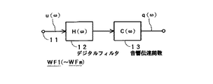
図7に示すように、
u(ω):仮想音源VSSの出力信号、つまり、原オーディオ信号
H(ω):適切な波面合成を実現するために信号u(ω)に畳み込む伝達関数、つまり、信号u(ω)をスピーカSP1〜SPmに供給するとき、信号u(ω)にあらかじめ畳み込む伝達関数
C(ω):スピーカSP1〜SPmから制御点CP1〜CPmまでの音響伝達関数
q(ω):波面合成により実際に制御点CP1〜CPxに再現される信号
とすると、原オーディオ信号u(ω)に、伝達関数C(ω)、H(ω)を畳み込んだ信号が、再現オーディオ信号q(ω)であるから、
q(ω)=C(ω)・H(ω)・u(ω)
となる。この場合、スピーカSP1〜SPmから制御点CP1〜CPxまでの伝達特性を求めておくことにより、伝達関数C(ω)を規定できる。
[5] Wavefront synthesis algorithm As shown in FIG.
u (ω): the output signal of the virtual sound source VSS, that is, the original audio signal H (ω): a transfer function that is convolved with the signal u (ω) in order to realize appropriate wavefront synthesis , that is, the signal u (ω). Transfer function C (ω) convolved with signal u (ω) in advance when supplied to SP1 to SPm: acoustic transfer function from speakers SP1 to SPm to control points CP1 to CPm q (ω): actual control points by wavefront synthesis Assuming that the signals reproduced in CP1 to CPx are signals obtained by convolution of the transfer functions C (ω) and H (ω) with the original audio signal u (ω), the reproduced audio signal q (ω)
q (ω) = C (ω) ・ H (ω) ・ u (ω)
It becomes. In this case, the transfer function C (ω) can be defined by obtaining transfer characteristics from the speakers SP1 to SPm to the control points CP1 to CPx.
そして、伝達関数H(ω)を制御すれば、このときの再現オーディオ信号q(ω)により適切な波面合成が実現されて図6により説明した平行平面波を形成することができる。 If the transfer function H (ω) is controlled, an appropriate wavefront synthesis is realized by the reproduced audio signal q (ω) at this time, and the parallel plane wave described with reference to FIG. 6 can be formed.
〔6〕 生成回路
上記の〔5〕にしたがって原オーディオ信号u(ω)から再現オーディオ信号q(ω)を生成する場合、その生成回路は例えば図8に示すデジタルフィルタ12により構成することができる。なお、この生成回路は、スピーカSP1〜SPmのそれぞれごとに設けられるもので、これを生成回路WF1〜WFmとする。また、図8における符号13は、〔5〕に記載したように、スピーカSP1〜SPmから制御点CP1〜CPxまでの音響伝達関数C(ω)を表す。
[6] Generation Circuit When the reproduction audio signal q (ω) is generated from the original audio signal u (ω) according to the above [5], the generation circuit can be configured by, for example, the
すなわち、生成回路WF1〜WFmのそれぞれにおいて、デジタル化された原オーディオ信号u(ω)が、入力端子11を通じてデジタルフィルタ12に供給されてスピーカ用のオーディオ信号とされ、このオーディオ信号が、スピーカSP1〜SPmのうち、対応するスピーカに供給される。なお、これらの生成回路WF1〜WFmはDSPにより構成することもできる。
That is, in each of the generation circuits WF1 to WFm, the digitized original audio signal u (ω) is supplied to the
したがって、スピーカSP1〜SPmの出力により仮想音源VSSが形成されるとともに、そのとき、フィルタ12の伝達関数H(ω)を所定の値にすることにより仮想音源VSSをスピーカSP1〜SPmから無限遠の位置に位置させることができる。また、フィルタ12の伝達関数H(ω)を変更することにより、図6AあるいはBに示すように、見込み角θを変更することができる。
Therefore, the virtual sound source VSS is formed by the outputs of the speakers SP1 to SPm, and at that time, the virtual sound source VSS is set at infinity from the speakers SP1 to SPm by setting the transfer function H (ω) of the
〔7〕 実施例(その1)
図9は、この発明による再生装置の一例を示す。この再生装置は、上述の〔1〕〜〔6〕にしたがって仮想音源VSSを形成するとともに、その仮想音源VSSの位置を波面合成面SSRから無限遠に設定するものである。なお、この例においては、スピーカSP1〜SPmの数mが24個(m=24)の場合である。また、スピーカSP1〜SP24は、例えば図4により説明したように、リスナの前方に水平に配置され、スピーカアレイが構成される。
[7] Example (1)
FIG. 9 shows an example of a playback apparatus according to the present invention. This playback apparatus forms a virtual sound source VSS according to the above [1] to [6], and sets the position of the virtual sound source VSS to infinity from the wavefront synthesis surface SSR. In this example, the number m of the speakers SP1 to SPm is 24 (m = 24). Further, as described with reference to FIG. 4, for example, the speakers SP1 to SP24 are horizontally disposed in front of the listener to constitute a speaker array.
図9において、CDプレーヤ、DVDプレーヤ、デジタル放送チューナなどの信号源SCから左チャンネルのデジタルオーディオ信号uL(ω)および右チャンネルのデジタルオーディオ信号uR(ω)が取り出され、信号uL(ω)が生成回路WF1〜WF12に供給されて再現オーディオ信号q(ω)に対応する再現オーディオ信号q1(ω)〜q12(ω)が生成される。また、信号uR(ω)が生成回路WF13〜WF24に供給されて再現オーディオ信号q(ω)に対応する再現オーディオ信号q13(ω)〜q24(ω)が生成される。 In Figure 9, CD players, DVD players, digital audio signal of the left channel from a signal source SC, such as a digital broadcasting tuner uL (omega) and the right-channel digital audio signal uR (omega) is taken out, signal uL (omega) Are supplied to the generation circuits WF1 to WF12, and reproduced audio signals q1 (ω) to q12 (ω) corresponding to the reproduced audio signal q (ω) are generated. Further, the signal uR (ω) is supplied to the generation circuits WF13 to WF24, and reproduced audio signals q13 (ω) to q24 (ω) corresponding to the reproduced audio signal q (ω) are generated.
そして、これら信号q1(ω)〜q12(ω)およびq13(ω)〜q24(ω)がD/Aコンバータ回路DA1〜DA12およびDA13〜DA24に供給されてアナログのオーディオ信号L1〜L12およびR13〜R24にD/A変換され、これら信号L1〜L12およびR13〜R24がパワーアンプPA1〜PA12およびPA13〜PA24を通じてスピーカSP1〜SP12およびSP13〜SP24に供給される。 These signals q1 (ω) to q12 (ω) and q13 (ω) to q24 (ω) are supplied to the D / A converter circuits DA1 to DA12 and DA13 to DA24, and the analog audio signals L1 to L12 and R13 to These signals L1 to L12 and R13 to R24 are supplied to speakers SP1 to SP12 and SP13 to SP24 through power amplifiers PA1 to PA12 and PA13 to PA24.
また、仮想音源VSSの位置を無限遠に設定するため、仮想音源の位置設定回路としてマイクロコンピュータ21が設けられるとともに、このマイクロコンピュータ21には、見込み角θを設定するためのデータDθが用意される。この場合、見込み角θは、例えば0°から45°までを5°ずつ変更できるものとされる。このため、データDθは、信号q1(ω)〜q24(ω)の数24と、見込み角θの設定可能数10とに対応して、24個×10組が用意され、操作スイッチ22を操作すると、そのうちの1組が選択される。
In order to set the position of the virtual sound source VSS to infinity, a
そして、この選択されたデータDθが、生成回路WF1〜WF24のデジタルフィルタ12〜12に供給されてそれらの伝達関数H(ω)〜H(ω)が制御される。
Then, the selected data Dθ is supplied to the
このような構成によれば、信号源SCから出力された左チャンネルのデジタルオーディオ信号uL(ω)は、生成回路WF1〜WF12により信号q1(ω)〜q12(ω)に変換され、この信号q1(ω)〜q12(ω)からD/A変換されたオーディオ信号L1〜L12がスピーカSP1〜SP12に供給されるので、図10AおよびBに示すように、スピーカSP1〜SP12からは左チャンネルの音波SWLが平行平面波の状態で出力される。同様に、右チャンネルのデジタルオーディオ信号uR(ω)により、スピーカSP13〜SP24からは右チャンネルの音波SWRが平行平面波の状態で出力される。 According to such a configuration, the digital audio signal uL (ω) of the left channel output from the signal source SC is converted into signals q1 (ω) to q12 (ω) by the generation circuits WF1 to WF12, and this signal q1 Since the audio signals L1 to L12 D / A converted from (ω) to q12 (ω) are supplied to the speakers SP1 to SP12, as shown in FIGS. 10A and 10B, the sound waves of the left channel are output from the speakers SP1 to SP12. SWL is output in the state of a parallel plane wave. Similarly, the right-channel sound wave SWR is output in the state of a parallel plane wave from the speakers SP13 to SP24 by the right-channel digital audio signal uR (ω).
したがって、リスナは信号源SCから出力されたオーディオ信号uL(ω)、uR(ω)をステレオで聴くことができるが、この場合、左チャンネルの音波SWLの受聴領域では、その領域のどこであっても左チャンネルの音量は等しく、右チャンネルの音波SWRの受聴領域では、その領域のどこであっても右チャンネルの音量は等しい。 Therefore, the listener can listen to the audio signals uL (ω) and uR (ω) output from the signal source SC in stereo. In this case, the listening area of the sound wave SWL of the left channel is anywhere in that area. The volume of the left channel is the same, and in the listening area of the sound wave SWR of the right channel, the volume of the right channel is the same everywhere in that area.
この結果、音波SWLおよび音波SWRの受聴領域、すなわち、図10において音波SWL、SWRが重畳している領域では、その受聴領域のどこであっても、左チャンネルの音量と右チャンネルの音量とが等しいことになる。したがって、リスナはその受聴領域内であれば、どこにいても左右のバランスのとれた音を聴くことができる。 As a result, in the listening area of the sound wave SWL and the sound wave SWR, that is, in the area where the sound waves SWL and SWR are superimposed in FIG. 10, the volume of the left channel is equal to the volume of the right channel regardless of the listening area. It will be. Therefore, the listener can listen to a balanced sound on the left and right wherever the listener is.
例えば複数のリスナがいる場合でも、そのすべてのリスナが最良の左右バランスで音楽などを聴くことができる。あるいはリスナが一人であっても、リスニングポイントが限定されず、好きな場所で聴くことができる。また、空間の広がり感も創出される。 For example, even if there are a plurality of listeners, all the listeners can listen to music with the best left / right balance. Alternatively, even if there is only one listener, the listening point is not limited and you can listen to it anywhere you like. It also creates a sense of space.
さらに、操作スイッチ22を操作してデータDθを選択すると、その選択されたデータDθにしたがって生成回路WF1〜WF24のデジタルフィルタ12〜12の特性が制御され、見込み角θが例えば図10AあるいはBに示すように、データDθに対応して0°から45°までを5°ずつ変更される。
Further, when the
こうして、見込み角θを変更することにより、リスナの状況に合わせて音波SWL、SWRの受聴領域を変更することができ、適切な再生音場を提供することができる。 Thus, by changing the prospective angle θ, the listening area of the sound waves SWL and SWR can be changed in accordance with the listener's situation, and an appropriate reproduction sound field can be provided.
〔8〕 実施例(その2)
図11は、この発明による再生装置の他の例を示す。この例においては、図12にも示すように、仮想音源VSSから出力される音波SWL、SWRが平行平面波となる幅を、〔7〕の場合よりも広くした場合である。
[8] Example (2)
FIG. 11 shows another example of the reproducing apparatus according to the present invention. In this example, as shown also in FIG. 12, the width in which the sound waves SWL and SWR output from the virtual sound source VSS become parallel plane waves is wider than in the case of [7].
すなわち、この例においても、〔7〕と同様、スピーカSP1〜SPmの数mが24個(m=24)の場合であり、これらスピーカSP1〜SP24は、例えば図4により説明したように、リスナの前方に水平に配置され、スピーカアレイが構成される。 That is, in this example as well as [7], the number m of speakers SP1 to SPm is 24 (m = 24). These speakers SP1 to SP24 are listeners as described with reference to FIG. Is arranged horizontally in front of the speaker array to constitute a speaker array.
そして、信号源SCから左および右チャンネルのデジタルオーディオ信号uL(ω)、uR(ω)が取り出され、信uL(ω)が生成回路WF1〜WF24に供給されて再現オーディオ信号q(ω)に対応する再現オーディオ信号q1(ω)〜q24(ω)が生成され、この信号q1(ω)〜q24(ω)が加算回路AC1〜AC24に供給される。 Then, the left and right channel digital audio signals uL (ω) and uR (ω) are extracted from the signal source SC, and the signal uL (ω) is supplied to the generation circuits WF1 to WF24 to be the reproduced audio signal q (ω). Corresponding reproduced audio signals q1 (ω) to q24 (ω) are generated, and these signals q1 (ω) to q24 (ω) are supplied to the adding circuits AC1 to AC24.
また、信号uR(ω)が生成回路WF25〜WF48に供給されて再現オーディオ信号q(ω)に対応する再現オーディオ信号q25(ω)〜q48(ω)が生成され、この信号q25(ω)〜q48(ω)が加算回路AC24〜AC1に供給される。こうして、加算回路AC1〜AC24からは、信号q1(ω)〜q24(ω)と、信号q48(ω)〜q25(ω)との加算信号S1〜S24
S1=q1(ω)+q48(ω)
S2=q2(ω)+q47(ω)
・・・・
S24=q24(ω)+q25(ω)
が取り出される。
Further, the signal uR (ω) is supplied to the generation circuits WF25 to WF48 to generate reproduction audio signals q25 (ω) to q48 (ω) corresponding to the reproduction audio signal q (ω), and this signal q 25 (ω) ˜q48 (ω) is supplied to the addition circuits AC24 to AC1. Thus, the addition circuits AC1 to AC24 add signals S1 to S24 of the signals q1 (ω) to q24 (ω) and the signals q48 (ω) to q25 (ω).
S1 = q1 (ω) + q48 (ω)
S2 = q2 (ω) + q47 (ω)
...
S24 = q24 (ω) + q25 (ω)
Is taken out.
そして、これら加算信号S1〜S24がD/Aコンバータ回路DA1〜DA24に供給されてアナログのオーディオ信号にD/A変換され、これら信号がパワーアンプPA1〜PA24を通じてスピーカSP1〜SP24に供給される。 These addition signals S1 to S24 are supplied to the D / A converter circuits DA1 to DA24 and D / A converted into analog audio signals, and these signals are supplied to the speakers SP1 to SP24 through the power amplifiers PA1 to PA24.
また、仮想音源VSSの位置を無限遠に設定するため、仮想音源の位置設定回路としてマイクロコンピュータ21が設けられるとともに、このマイクロコンピュータ21には、見込み角θを設定するためのデータDθが用意される。この場合、見込み角θは、例えば0°から45°までを5°ずつ変更できるものとすれば、データDθは、信号q1(ω)〜q48(ω)の数48と、見込み角θの設定可能数10とに対応して、48個×10組が用意され、操作スイッチ22を操作すると、そのうちの1組が選択される。そして、この選択されたデータDθが、生成回路WF1〜WF24のデジタルフィルタ12〜12に供給されてそれらの伝達関数H(ω)〜H(ω)が制御される。
In order to set the position of the virtual sound source VSS to infinity, a
このような構成によれば、加算信号S1〜S24は、左チャンネルの再現オーディオ信号q1(ω)〜q24(ω)と、右チャンネルの再現オーディオ信号q48(ω)〜q25(ω)との加算信号であるから、図12AあるいはBに示すように、スピーカSP1〜SP24からは、左チャンネルの音波SWLと、右チャンネル音波SWRとが線形加算されて出力されることになる。 According to such a configuration, the addition signals S1 to S24 are additions of the left channel reproduction audio signals q1 (ω) to q24 (ω) and the right channel reproduction audio signals q48 (ω) to q25 (ω). Since it is a signal, as shown in FIG. 12A or B, the left channel sound wave SWL and the right channel sound wave SWR are linearly added and output from the speakers SP1 to SP24.
そして、操作スイッチ22を操作してデータDθを選択すると、見込み角θが例えば図12AあるいはBに示すように変更される。
When the
こうして、この再生装置においても、左および右チャンネルの音波SWL、SWRを平行平面波の状態で出力することができるので、リスナは信号源SCから出力されたオーディオ信号uL(ω)、uR(ω)をステレオで聴くことができるとともに、図12において音波SWL、SWRが重畳している領域であれば、どこにいても左右のバランスのとれた音を聴くことができる。 Thus, in this reproducing apparatus as well, the left and right channel sound waves SWL, SWR can be output in the state of parallel plane waves, so that the listener can output the audio signals uL (ω), uR (ω) output from the signal source SC. Can be heard in stereo, and in the region where the sound waves SWL and SWR are superimposed in FIG.
そして、その場合、図12にからも明らかなように、仮想音源VSSから出力される音波SWL、SWRが平行平面波となる幅が、図10の場合よりも広くなり、したがって、より広い範囲で左右のバランスのとれた音を聴くことができる。また、θ=0の場合はモノラル再生となるので、見込み角θによりステレオ感を調整することもできる。 In this case, as is clear from FIG. 12, the widths of the sound waves SWL and SWR output from the virtual sound source VSS become parallel plane waves are wider than those in FIG. You can hear a balanced sound. Further, since the reproduction is monaural when θ = 0, the stereo feeling can be adjusted by the prospective angle θ.
〔9〕 実施例(その3)
図13は、平行平面波によるステレオ再生を、左右チャンネルに加えて中央チャンネルを有する3チャンネルステレオに適用した場合の一例を示す。このような3チャンネルステレオは、5チャンネルステレオの左右側方(あるいは左右後方)のチャンネルを、左右前方のチャンネルに混合して実現できる。
[9] Example (part 3)
FIG. 13 shows an example in which stereo reproduction using parallel plane waves is applied to a three-channel stereo having a center channel in addition to the left and right channels. Such 3-channel stereo can be realized by mixing the left and right side (or left and right rear) channels of the 5-channel stereo with the left and right front channels.
そして、この3チャンネルステレオにおいては、スピーカSP1〜SP24のうち、左側の8個のスピーカSP1〜SP8に左チャンネルの再現オーディオ信号q1(ω)〜q8(ω)のアナログ信号が供給され、中央の8個のスピーカSP9〜SP16に中央チャンネルの再現オーディオ信号q9(ω)〜q16(ω)のアナログ信号が供給され、右側の8個のスピーカSP17〜SP24に右チャンネルの再現オーディオ信号q17(ω)〜q24(ω)のアナログ信号が供給される。なお、再現オーディオ信号q1(ω)〜q8(ω)、q9(ω)〜q16(ω)、q17(ω)〜q24(ω)の生成方法は上述のとおりである。 In this three-channel stereo, the left channel reproduction audio signals q1 (ω) to q8 (ω) are supplied to the left eight speakers SP1 to SP8 out of the speakers SP1 to SP24, and The analog signals of the center channel reproduction audio signals q9 (ω) to q16 (ω) are supplied to the eight speakers SP9 to SP16, and the right channel reproduction audio signal q17 (ω) is supplied to the right eight speakers SP17 to SP24. An analog signal of ˜q24 (ω) is supplied. The method of generating the reproduced audio signals q1 (ω) to q8 (ω), q9 (ω) to q16 (ω), and q17 (ω) to q24 (ω) is as described above.
したがって、図13に示すように左右チャンネルの音波SWL、SWRが平行平面波の状態で得ることができるとともに、中央チャンネルの音波SWCも平行平面波の状態で得ることができる。そして、例えば図13AあるいはBに示すように、音波SWL、SWRの見込み角θを変更することもできる。 Therefore, as shown in FIG. 13, the sound waves SWL and SWR of the left and right channels can be obtained in the state of parallel plane waves, and the sound wave SWC of the center channel can also be obtained in the state of parallel plane waves. For example, as shown in FIG. 13A or B, the expected angle θ of the sound waves SWL and SWR can be changed.
〔10〕 実施例(その4)
図14は、スピーカから出力される平行平面波を壁面で反射させてリスナに届ける場合である。すなわち、スピーカSP1〜SP24のうち、左側のスピーカSP1〜SP12に右チャンネルの再現オーディオ信号q13(ω)〜q24(ω)のアナログ信号が供給されて右チャンネルの音波SWRが平行平面波の状態で出力され、この音波SWRが右側の壁面WRで反射される。
[10] Example (part 4)
FIG. 14 shows a case where the parallel plane wave output from the speaker is reflected by the wall surface and delivered to the listener. That is, among the speakers SP1 to SP24, the left speaker SP1 to SP12 is supplied with the analog signal of the right channel reproduction audio signal q13 (ω) to q24 (ω), and the right channel sound wave SWR is output in the state of a parallel plane wave. The sound wave SWR is reflected by the right wall surface WR.
また、スピーカSP1〜SP24のうち、右側のスピーカSP13〜SP24に左チャンネルの再現オーディオ信号q1(ω)〜q12(ω)のアナログ信号が供給され左チャンネルの音波SWLが平行平面波の状態で出力され、この音波SWLが左側の壁面WLで反射される。したがって、これら壁面WL、WRで反射した音波SWL、SWRにより音場が形成される。 Also, among the speakers SP1 to SP24, the left channel reproduction audio signals q1 (ω) to q12 (ω) are supplied to the right speakers SP13 to SP24, and the left channel sound wave SWL is output in a parallel plane wave state. The sound wave SWL is reflected by the left wall surface WL. Therefore, a sound field is formed by the sound waves SWL and SWR reflected by the wall surfaces WL and WR.
〔11〕 その他
上述においては、複数m個のスピーカSP1〜SPmを1列に水平に配置してスピーカアレイを構成した場合であるが、垂直面内に複数行×複数列にわたってマトリックス状に配置してスピーカアレイを構成することもできる。また、上述においては、スピーカSP1〜SPmと、波面合成面SSRとは平行であるとしたが、平行である必要はなく、さらに、スピーカSP1〜SPmは直線状あるいは平面状に配置しなくてもよい。
[11] Others In the above description, a speaker array is configured by arranging a plurality of m speakers SP1 to SPm horizontally in one column, but arranged in a matrix over a plurality of rows and a plurality of columns in a vertical plane. A speaker array can also be configured. In the above description, the speakers SP1 to SPm and the wavefront synthesis surface SSR are parallel to each other. However, the speakers SP1 to SPm are not necessarily parallel, and the speakers SP1 to SPm may not be arranged linearly or planarly. Good.
また、聴覚の方向に関する感度や識別能力は、水平方向には高いが、垂直方向には低いので、スピーカSP1〜SPmを、十字状あるいは逆T字状に配置してもよい。さらに、AVシステムと一体化するような場合には、スピーカSP1〜SPmをディスプレイの上下左右に枠状に配置したり、ディスプレイの上あるいは下と左右とに冂字状あるいは凵字状に配置したりすることもできる。また、この発明は、後方のスピーカや側方のスピーカ、さらには、上下方向に音波を出力するスピーカシステムにも適用することができる。さらに、この発明は、一般の2チャンネルステレオや5.1チャンネルオーディオと組み合わせることもできる。 Moreover, since the sensitivity and discrimination ability regarding the direction of hearing are high in the horizontal direction but low in the vertical direction, the speakers SP1 to SPm may be arranged in a cross shape or an inverted T shape. Furthermore, when integrating with the AV system, the speakers SP1 to SPm are arranged in a frame shape on the top, bottom, left and right of the display, or in a square shape or a square shape on the top, bottom, left and right of the display. You can also. The present invention can also be applied to a rear speaker, a side speaker, and a speaker system that outputs sound waves in the vertical direction. Furthermore, the present invention can be combined with general 2-channel stereo or 5.1-channel audio.
〔略語の一覧〕
AV :Audio and Visual
CD :Compact Disc
D/A:Digital to Analog
DSP:Digital Signal Processor
[List of abbreviations]
AV: Audio and Visual
CD: Compact Disc
D / A: Digital to Analog
DSP: Digital Signal Processor
12…デジタルフィルタ、13…音響伝達関数、21…マイクロコンピュータ、22…操作スイッチ、AC1〜AC24…加算回路、DA1〜DA24…D/Aコンバータ回路、PA1〜PA24…アンプ、SC…信号源、SP1〜SPm…スピーカ、WF1〜WFm…生成回路 12 ... digital filter, 13 ... acoustic transfer functions, 21 ... microcomputer 22 ... operation switch, AC1~AC24 ... adder circuit, DA1~DA24 ... D / A converter circuit, PA1~PA24 ... amplifier, SC ... signal source, SP1 to SPm ... speaker, WF1 to WFm ... generation circuit
Claims (4)
上記複数のスピーカのそれぞれから、これら複数のスピーカと受聴領域との間に位置する波面合成面上の複数の制御点までの伝達関数を伝達関数Aとし、
上記複数のスピーカのそれぞれごとに設けられる伝達関数を伝達関数Bとするとき、上記複数のスピーカのそれぞれに供給されるオーディオ信号に、上記伝達関数Aおよび上記伝達関数Bを畳み込むことにより、上記受聴領域内に波面合成を行って上記オーディオ信号を再生する再生方法であって、
第1の上記スピーカアレイに第1チャンネルのオーディオ信号を供給するとともに、上記第1のスピーカアレイにおける上記複数のスピーカのそれぞれごとに、第1の上記伝達関数Aおよび第1の上記伝達関数Bの少なくとも一方を制御して第1の上記波面合成を行い、
この第1の波面合成により無限遠方に第1の仮想音源を形成し、
第2の上記スピーカアレイに第2チャンネルのオーディオ信号を供給するとともに、上記第2のスピーカアレイにおける上記複数のスピーカのそれぞれごとに、第2の上記伝達関数Aおよび第2の上記伝達関数Bの少なくとも一方を制御して第2の上記波面合成を行い、
この第2の波面合成により無限遠方に第2の仮想音源を形成するとともに、
上記第1および第2の仮想音源により得られる第1および第2の音波の進行方向が交差するように、上記第1および第2の伝達関数Aと、上記第1および第2の伝達関数Bとの少なくとも一方を制御するようにし、
上記第1のスピーカアレイを構成する複数のスピーカの一部あるいは全部と、上記第2のスピーカアレイを構成する複数のスピーカの一部あるいは全部とに対して、上記第1チャンネルのオーディオ信号と、上記第2チャンネルのオーディオ信号とを共通に供給する
ようにしたオーディオ信号の再生方法。 A speaker array is composed of a plurality of speakers,
A transfer function from each of the plurality of speakers to a plurality of control points on the wavefront synthesis surface located between the plurality of speakers and the listening area is defined as a transfer function A,
When the transfer function provided for each of the plurality of speakers is a transfer function B, the audio signal supplied to each of the plurality of speakers is convoluted with the transfer function A and the transfer function B so that the listening is performed. A reproduction method for reproducing the audio signal by performing wavefront synthesis in an area,
A first channel audio signal is supplied to the first speaker array, and the first transfer function A and the first transfer function B are set for each of the plurality of speakers in the first speaker array. Controlling at least one to perform the first wavefront synthesis,
This first wavefront synthesis forms a first virtual sound source at infinity,
A second channel audio signal is supplied to the second speaker array, and the second transfer function A and the second transfer function B are set for each of the plurality of speakers in the second speaker array. Performing at least one of the above wavefront synthesis by controlling at least one of
By forming the second virtual sound source at infinity by this second wavefront synthesis,
The first and second transfer functions A and the first and second transfer functions B so that the traveling directions of the first and second sound waves obtained by the first and second virtual sound sources intersect each other. so as to control at least one of the,
The audio signal of the first channel for a part or all of the plurality of speakers constituting the first speaker array and part or all of the plurality of speakers constituting the second speaker array; A method for reproducing an audio signal, wherein the audio signal of the second channel is supplied in common .
上記第1の伝達関数Aおよび上記第2の伝達関数Aを制御することにより、上記第1および第2の音波の進行方向の交差する角度を可変とする
ようにしたオーディオ信号の再生方法。 The method of reproducing an audio signal according to claim 1,
A method of reproducing an audio signal, wherein the angle at which the traveling directions of the first and second sound waves intersect is made variable by controlling the first transfer function A and the second transfer function A.
上記複数のスピーカのそれぞれから、これら複数のスピーカと受聴領域との間に位置する波面合成面上の複数の制御点までの伝達関数を伝達関数Aとし、
上記複数のスピーカのそれぞれごとに設けられる伝達関数を伝達関数Bとするとき、
上記複数のスピーカのそれぞれに供給されるオーディオ信号に、上記伝達関数Aおよび上記伝達関数Bを畳み込むことにより、上記受聴領域内に波面合成を行って上記オーディオ信号を再生する再生装置であって、
第1の上記スピーカアレイに第1チャンネルのオーディオ信号を供給するとともに、上記第1のスピーカアレイにおける上記複数のスピーカのそれぞれごとに、第1の上記伝達関数Aおよび第1の上記伝達関数Bの少なくとも一方を制御して第1の上記波面合成を行うことにより、無限遠方に第1の仮想音源を形成する第1の処理回路と、
第2の上記スピーカアレイに第2チャンネルのオーディオ信号を供給するとともに、上記第2のスピーカアレイにおける上記複数のスピーカのそれぞれごとに、第2の上記伝達関数Aおよび第2の上記伝達関数Bの少なくとも一方を制御して第2の上記波面合成を行うことにより、無限遠方に第2の仮想音源を形成する第2の処理回路と、
上記第1および第2の仮想音源により得られる第1および第2の音波の進行方向が交差するように、上記第1および第2の伝達関数Aと、上記第1および第2の伝達関数Bとの少なくとも一方を制御する制御回路と
を有し、
上記第1のスピーカアレイを構成する複数のスピーカの一部あるいは全部と、上記第2のスピーカアレイを構成する複数のスピーカの一部あるいは全部とが共通である
ようにしたオーディオ信号の再生装置。 A speaker array is composed of a plurality of speakers,
A transfer function from each of the plurality of speakers to a plurality of control points on the wavefront synthesis surface located between the plurality of speakers and the listening area is defined as a transfer function A,
When a transfer function provided for each of the plurality of speakers is a transfer function B,
A playback device that reproduces the audio signal by performing wavefront synthesis in the listening area by convolving the transfer function A and the transfer function B with an audio signal supplied to each of the plurality of speakers,
A first channel audio signal is supplied to the first speaker array, and the first transfer function A and the first transfer function B are set for each of the plurality of speakers in the first speaker array. A first processing circuit that forms a first virtual sound source at infinity by controlling at least one of the first wavefront synthesis;
A second channel audio signal is supplied to the second speaker array, and the second transfer function A and the second transfer function B are set for each of the plurality of speakers in the second speaker array. A second processing circuit that forms a second virtual sound source at infinity by controlling at least one of the above and performing the second wavefront synthesis;
The first and second transfer functions A and the first and second transfer functions B so that the traveling directions of the first and second sound waves obtained by the first and second virtual sound sources intersect each other. It has a control circuit for controlling at least one of the,
A part or all of the plurality of speakers constituting the first speaker array and a part or all of the plurality of speakers constituting the second speaker array are common.
An audio signal playback device.
上記第1の伝達関数Aおよび上記第2の伝達関数Aを制御して上記第1および第2の音波の進行方向の交差する角度を可変とする制御回路を有する
ことを特徴とするオーディオ信号の再生装置。 The audio signal reproducing apparatus according to claim 3 , wherein
An audio signal comprising: a control circuit that controls the first transfer function A and the second transfer function A to vary an angle at which the traveling directions of the first and second sound waves intersect; Playback device.
Priority Applications (5)
| Application Number | Priority Date | Filing Date | Title |
|---|---|---|---|
| JP2004297093A JP4625671B2 (en) | 2004-10-12 | 2004-10-12 | Audio signal reproduction method and reproduction apparatus therefor |
| EP05256227A EP1648198B1 (en) | 2004-10-12 | 2005-10-05 | Method and apparatus for reproducing an audio signal |
| KR1020050094815A KR101177853B1 (en) | 2004-10-12 | 2005-10-10 | Audio signal reproduction apparatus and method thereof |
| US11/248,960 US7801313B2 (en) | 2004-10-12 | 2005-10-11 | Method and apparatus for reproducing audio signal |
| CN200510116312XA CN1761368B (en) | 2004-10-12 | 2005-10-12 | Method and apparatus for reproducing audio signal |
Applications Claiming Priority (1)
| Application Number | Priority Date | Filing Date | Title |
|---|---|---|---|
| JP2004297093A JP4625671B2 (en) | 2004-10-12 | 2004-10-12 | Audio signal reproduction method and reproduction apparatus therefor |
Publications (3)
| Publication Number | Publication Date |
|---|---|
| JP2006114945A JP2006114945A (en) | 2006-04-27 |
| JP2006114945A5 JP2006114945A5 (en) | 2006-06-15 |
| JP4625671B2 true JP4625671B2 (en) | 2011-02-02 |
Family
ID=35539149
Family Applications (1)
| Application Number | Title | Priority Date | Filing Date |
|---|---|---|---|
| JP2004297093A Expired - Fee Related JP4625671B2 (en) | 2004-10-12 | 2004-10-12 | Audio signal reproduction method and reproduction apparatus therefor |
Country Status (5)
| Country | Link |
|---|---|
| US (1) | US7801313B2 (en) |
| EP (1) | EP1648198B1 (en) |
| JP (1) | JP4625671B2 (en) |
| KR (1) | KR101177853B1 (en) |
| CN (1) | CN1761368B (en) |
Families Citing this family (20)
| Publication number | Priority date | Publication date | Assignee | Title |
|---|---|---|---|---|
| JP2006115396A (en) * | 2004-10-18 | 2006-04-27 | Sony Corp | Reproduction method of audio signal and reproducing apparatus therefor |
| GB0514361D0 (en) * | 2005-07-12 | 2005-08-17 | 1 Ltd | Compact surround sound effects system |
| DE102005033238A1 (en) * | 2005-07-15 | 2007-01-25 | Fraunhofer-Gesellschaft zur Förderung der angewandten Forschung e.V. | Apparatus and method for driving a plurality of loudspeakers by means of a DSP |
| DE102005033239A1 (en) * | 2005-07-15 | 2007-01-25 | Fraunhofer-Gesellschaft zur Förderung der angewandten Forschung e.V. | Apparatus and method for controlling a plurality of loudspeakers by means of a graphical user interface |
| JP4449998B2 (en) * | 2007-03-12 | 2010-04-14 | ヤマハ株式会社 | Array speaker device |
| JP4488036B2 (en) | 2007-07-23 | 2010-06-23 | ヤマハ株式会社 | Speaker array device |
| JP5577597B2 (en) | 2009-01-28 | 2014-08-27 | ヤマハ株式会社 | Speaker array device, signal processing method and program |
| JP4810621B1 (en) * | 2010-09-07 | 2011-11-09 | シャープ株式会社 | Audio signal conversion apparatus, method, program, and recording medium |
| JP5720158B2 (en) * | 2010-09-22 | 2015-05-20 | ヤマハ株式会社 | Binaural recorded sound signal playback method and playback device |
| WO2013057948A1 (en) * | 2011-10-21 | 2013-04-25 | パナソニック株式会社 | Acoustic rendering device and acoustic rendering method |
| US10149058B2 (en) | 2013-03-15 | 2018-12-04 | Richard O'Polka | Portable sound system |
| EP2971393A4 (en) | 2013-03-15 | 2016-11-16 | Richard O'polka | Portable sound system |
| CN103347245B (en) * | 2013-07-01 | 2015-03-25 | 武汉大学 | Method and device for restoring sound source azimuth information in stereophonic sound system |
| DE102013013378A1 (en) * | 2013-08-10 | 2015-02-12 | Advanced Acoustic Sf Gmbh | Distribution of virtual sound sources |
| USD740784S1 (en) | 2014-03-14 | 2015-10-13 | Richard O'Polka | Portable sound device |
| JP6228945B2 (en) * | 2015-02-04 | 2017-11-08 | 日本電信電話株式会社 | Sound field reproduction apparatus, sound field reproduction method, and program |
| EP3266224B1 (en) * | 2015-04-08 | 2021-05-19 | Huawei Technologies Co., Ltd. | Apparatus and method for driving an array of loudspeakers |
| US10531196B2 (en) * | 2017-06-02 | 2020-01-07 | Apple Inc. | Spatially ducking audio produced through a beamforming loudspeaker array |
| CN109151661B (en) * | 2018-09-04 | 2020-02-28 | 音王电声股份有限公司 | Method for forming ring screen loudspeaker array and virtual sound source |
| JP2023131544A (en) * | 2022-03-09 | 2023-09-22 | カシオ計算機株式会社 | Acoustic output device, acoustic output method, and program |
Citations (4)
| Publication number | Priority date | Publication date | Assignee | Title |
|---|---|---|---|---|
| JPH04132499A (en) * | 1990-09-25 | 1992-05-06 | Matsushita Electric Ind Co Ltd | Sound image controller |
| JP2001517005A (en) * | 1997-09-09 | 2001-10-02 | ローベルト ボツシユ ゲゼルシヤフト ミツト ベシユレンクテル ハフツング | Method and apparatus for reproducing a stereo audio signal |
| JP2002505058A (en) * | 1997-06-17 | 2002-02-12 | ブリティッシュ・テレコミュニケーションズ・パブリック・リミテッド・カンパニー | Playing spatially shaped audio |
| WO2004047485A1 (en) * | 2002-11-21 | 2004-06-03 | Fraunhofer-Gesellschaft zur Förderung der angewandten Forschung e.V. | Audio playback system and method for playing back an audio signal |
Family Cites Families (4)
| Publication number | Priority date | Publication date | Assignee | Title |
|---|---|---|---|---|
| EP1224037B1 (en) * | 1999-09-29 | 2007-10-31 | 1... Limited | Method and apparatus to direct sound using an array of output transducers |
| US7515719B2 (en) * | 2001-03-27 | 2009-04-07 | Cambridge Mechatronics Limited | Method and apparatus to create a sound field |
| US7706544B2 (en) * | 2002-11-21 | 2010-04-27 | Fraunhofer-Geselleschaft Zur Forderung Der Angewandten Forschung E.V. | Audio reproduction system and method for reproducing an audio signal |
| JP2004297093A (en) | 2004-07-15 | 2004-10-21 | Matsushita Electric Ind Co Ltd | Electronic component and packaging method therefor |
-
2004
- 2004-10-12 JP JP2004297093A patent/JP4625671B2/en not_active Expired - Fee Related
-
2005
- 2005-10-05 EP EP05256227A patent/EP1648198B1/en not_active Expired - Fee Related
- 2005-10-10 KR KR1020050094815A patent/KR101177853B1/en active IP Right Grant
- 2005-10-11 US US11/248,960 patent/US7801313B2/en not_active Expired - Fee Related
- 2005-10-12 CN CN200510116312XA patent/CN1761368B/en not_active Expired - Fee Related
Patent Citations (5)
| Publication number | Priority date | Publication date | Assignee | Title |
|---|---|---|---|---|
| JPH04132499A (en) * | 1990-09-25 | 1992-05-06 | Matsushita Electric Ind Co Ltd | Sound image controller |
| JP2002505058A (en) * | 1997-06-17 | 2002-02-12 | ブリティッシュ・テレコミュニケーションズ・パブリック・リミテッド・カンパニー | Playing spatially shaped audio |
| JP2001517005A (en) * | 1997-09-09 | 2001-10-02 | ローベルト ボツシユ ゲゼルシヤフト ミツト ベシユレンクテル ハフツング | Method and apparatus for reproducing a stereo audio signal |
| WO2004047485A1 (en) * | 2002-11-21 | 2004-06-03 | Fraunhofer-Gesellschaft zur Förderung der angewandten Forschung e.V. | Audio playback system and method for playing back an audio signal |
| JP2006507727A (en) * | 2002-11-21 | 2006-03-02 | フラウンホーファー−ゲゼルシャフト・ツール・フェルデルング・デル・アンゲヴァンテン・フォルシュング・アインゲトラーゲネル・フェライン | Audio reproduction system and method for reproducing an audio signal |
Also Published As
| Publication number | Publication date |
|---|---|
| KR101177853B1 (en) | 2012-08-28 |
| JP2006114945A (en) | 2006-04-27 |
| KR20060052141A (en) | 2006-05-19 |
| EP1648198A3 (en) | 2009-02-25 |
| EP1648198A2 (en) | 2006-04-19 |
| EP1648198B1 (en) | 2012-08-08 |
| US7801313B2 (en) | 2010-09-21 |
| CN1761368A (en) | 2006-04-19 |
| CN1761368B (en) | 2010-09-29 |
| US20060078132A1 (en) | 2006-04-13 |
Similar Documents
| Publication | Publication Date | Title |
|---|---|---|
| KR101177853B1 (en) | Audio signal reproduction apparatus and method thereof | |
| KR101177856B1 (en) | Audio signal reproduction method and apparatus thereof | |
| TWI489887B (en) | Virtual audio processing for loudspeaker or headphone playback | |
| JP4251077B2 (en) | Speaker device | |
| US9031267B2 (en) | Loudspeaker array providing direct and indirect radiation from same set of drivers | |
| US8824709B2 (en) | Generation of 3D sound with adjustable source positioning | |
| US7978860B2 (en) | Playback apparatus and playback method | |
| JP2009077379A (en) | Stereoscopic sound reproduction equipment, stereophonic sound reproduction method, and computer program | |
| EP2797795A1 (en) | Systems, methods, and apparatus for directing sound in a vehicle | |
| EP3022947B1 (en) | Method for processing of sound signals | |
| Bates | The composition and performance of spatial music | |
| JP2993418B2 (en) | Sound field effect device | |
| CN103503485A (en) | A method and an apparatus for generating an acoustic signal with an enhanced spatial effect | |
| KR20120038891A (en) | Audio system and down mixing method of audio signals using thereof | |
| JP4725234B2 (en) | Sound field reproduction method, sound signal processing method, sound signal processing apparatus | |
| JPH021440B2 (en) | ||
| WO2008010086A2 (en) | Loudspeaker system and loudspeaker having a tweeter array and an audio signal processing unit | |
| JP6236503B1 (en) | Acoustic device, display device, and television receiver | |
| Zotter et al. | XY, MS, and first-order Ambisonics | |
| CN109923877B (en) | Apparatus and method for weighting stereo audio signal | |
| JP2006121125A (en) | Reproducing apparatus of audio signal and reproducing method thereof | |
| WO2018160776A1 (en) | Multiple dispersion standalone stereo loudspeakers | |
| CN107534813B (en) | Apparatus for reproducing multi-channel audio signal and method of generating multi-channel audio signal | |
| EP3726858A1 (en) | Lower layer reproduction | |
| JP2001016698A (en) | Sound field reproduction system |
Legal Events
| Date | Code | Title | Description |
|---|---|---|---|
| A521 | Request for written amendment filed |
Free format text: JAPANESE INTERMEDIATE CODE: A523 Effective date: 20060309 |
|
| A621 | Written request for application examination |
Free format text: JAPANESE INTERMEDIATE CODE: A621 Effective date: 20060309 |
|
| A131 | Notification of reasons for refusal |
Free format text: JAPANESE INTERMEDIATE CODE: A131 Effective date: 20071106 |
|
| A521 | Request for written amendment filed |
Free format text: JAPANESE INTERMEDIATE CODE: A523 Effective date: 20071226 |
|
| A131 | Notification of reasons for refusal |
Free format text: JAPANESE INTERMEDIATE CODE: A131 Effective date: 20080213 |
|
| A521 | Request for written amendment filed |
Free format text: JAPANESE INTERMEDIATE CODE: A523 Effective date: 20080407 |
|
| A02 | Decision of refusal |
Free format text: JAPANESE INTERMEDIATE CODE: A02 Effective date: 20080508 |
|
| A521 | Request for written amendment filed |
Free format text: JAPANESE INTERMEDIATE CODE: A523 Effective date: 20080704 |
|
| A911 | Transfer to examiner for re-examination before appeal (zenchi) |
Free format text: JAPANESE INTERMEDIATE CODE: A911 Effective date: 20080725 |
|
| A912 | Re-examination (zenchi) completed and case transferred to appeal board |
Free format text: JAPANESE INTERMEDIATE CODE: A912 Effective date: 20080815 |
|
| RD03 | Notification of appointment of power of attorney |
Free format text: JAPANESE INTERMEDIATE CODE: A7423 Effective date: 20090810 |
|
| RD04 | Notification of resignation of power of attorney |
Free format text: JAPANESE INTERMEDIATE CODE: A7424 Effective date: 20091002 |
|
| A521 | Request for written amendment filed |
Free format text: JAPANESE INTERMEDIATE CODE: A523 Effective date: 20100921 |
|
| A01 | Written decision to grant a patent or to grant a registration (utility model) |
Free format text: JAPANESE INTERMEDIATE CODE: A01 |
|
| A61 | First payment of annual fees (during grant procedure) |
Free format text: JAPANESE INTERMEDIATE CODE: A61 Effective date: 20101108 |
|
| R150 | Certificate of patent or registration of utility model |
Ref document number: 4625671 Country of ref document: JP Free format text: JAPANESE INTERMEDIATE CODE: R150 Free format text: JAPANESE INTERMEDIATE CODE: R150 |
|
| FPAY | Renewal fee payment (event date is renewal date of database) |
Free format text: PAYMENT UNTIL: 20131112 Year of fee payment: 3 |
|
| R250 | Receipt of annual fees |
Free format text: JAPANESE INTERMEDIATE CODE: R250 |
|
| R250 | Receipt of annual fees |
Free format text: JAPANESE INTERMEDIATE CODE: R250 |
|
| R250 | Receipt of annual fees |
Free format text: JAPANESE INTERMEDIATE CODE: R250 |
|
| R250 | Receipt of annual fees |
Free format text: JAPANESE INTERMEDIATE CODE: R250 |
|
| R250 | Receipt of annual fees |
Free format text: JAPANESE INTERMEDIATE CODE: R250 |
|
| R250 | Receipt of annual fees |
Free format text: JAPANESE INTERMEDIATE CODE: R250 |
|
| R250 | Receipt of annual fees |
Free format text: JAPANESE INTERMEDIATE CODE: R250 |
|
| R250 | Receipt of annual fees |
Free format text: JAPANESE INTERMEDIATE CODE: R250 |
|
| LAPS | Cancellation because of no payment of annual fees |