JP4623609B2 - Imaging / display device for video conference - Google Patents
Imaging / display device for video conference Download PDFInfo
- Publication number
- JP4623609B2 JP4623609B2 JP2000168858A JP2000168858A JP4623609B2 JP 4623609 B2 JP4623609 B2 JP 4623609B2 JP 2000168858 A JP2000168858 A JP 2000168858A JP 2000168858 A JP2000168858 A JP 2000168858A JP 4623609 B2 JP4623609 B2 JP 4623609B2
- Authority
- JP
- Japan
- Prior art keywords
- image
- display
- video
- imaging device
- video camera
- Prior art date
- Legal status (The legal status is an assumption and is not a legal conclusion. Google has not performed a legal analysis and makes no representation as to the accuracy of the status listed.)
- Expired - Fee Related
Links
Images


Landscapes
- Studio Devices (AREA)
- Two-Way Televisions, Distribution Of Moving Picture Or The Like (AREA)
Description
【0001】
【発明の属する技術分野】
本発明は、ビデオカメラ付きビデオ会議用ディスプレイ装置からなるビデオ会議用撮像/表示装置に関し、更に具体的には、例えばビデオ会議において、大型画面のディスプレイに対応したビデオ会議用カメラの対話相手のディスプレイの画像面に映し出す複数の会議出席者の顔の映像が、対話相手のディスプレイの画像面に自然に向かい合った姿で映し出されるようにする技術であり、撮影環境及び画像データの取り扱いを行う場合に好適なビデオ会議用撮像/表示装置に関する。
【0002】
【従来の技術】
従来より、企業等におけるビデオ会議を行うためのシステムが各種提案されている。図24〜図26に従来のビデオ会議用ディスプレイとカメラシステムの第1の例を示す。図24は会議用ディスプレイと会議出席者と会議出席者が囲むテーブルを側面から観た場合の図である。図25はその上面から観た場合の図である。図26はその場合のビデオカメラが撮像したカメラ画像のイメージ図である。
【0003】
図24及び図25のように、従来、ビデオ会議等に使用するビデオカメラは、首振り可能な雲台に載せて、或いは雲台付きのビデオカメラをディスプレイの上に載せて、会議出席者の模様を撮影し、会議相手に有線及び無線の個別或いはネットワーク回線等により、上記撮影画像を圧縮或いは非圧縮処理を介して伝送し、会議相手のディスプレイにしかるべき復調手段を介して表示し、会議を行っていた。
【0004】
図27〜図29に従来のビデオ会議用ディスプレイとカメラシステムの第2の例を示す。図27は会議用ディスプレイと会議出席者と会議出席者が囲むテーブルを側面から観た場合の図である。図28はその上面から観た場合の図である。図29はその場合のビデオカメラが撮像したカメラ画像のイメージ図である。
【0005】
図27及び図28のように、従来、ビデオ会議等に使用するビデオカメラは、ディスプレイの前面下などに設置して、会議出席者の模様を撮影し、会議相手に有線及び無線の個別或いはネットワーク回線等により、上記撮影画像を圧縮或いは非圧縮処理を介して伝送し、会議相手のディスプレイにしかるべき復調手段を介して表示し、会議を行っていた。また、この場合、双方の或いは片方の、会議グループのディスプレイ画面上は、上記会議相手のビデオカメラの映像と、その他の例えばコンピュータの画像を切り替えて、或いは同時にマルチ画面などとして表示していた。
【0006】
図30は従来例のビデオ会議用ディスプレイ、ビデオカメラ等からなるシステムの構成を示すブロック図である。従来例のシステムは、ディスプレイ2、103、ビデオカメラ3、102、マイクロフォン11、101、スピーカ12、104、ビデオ会議端末13、105、コーデック14、106、伝送回線15、107を備えている。ビデオカメラ3、102で撮影した会議の画像やマイクロフォン11、101で集音した音声は、ビデオ会議端末13、105、コーデック14、106、伝送回線15、107を介して会議相手に伝送される。
【0007】
【発明が解決しようとする課題】
近年、上記のような用途のディスプレイは、表示するソースではパーソナルコンピュータの表示解像度がSXGAやXGA(eXtended Graphics Array)といった高精細化や、テレビでは放送のデジタルテレビ化などによるハイビジョン等のコンテンツの増加に伴い高精細化の方向に進み、それに伴いディスプレイの表示画面のサイズが大きくなる傾向にある。
【0008】
特に近年は、リアデータプロジェクション装置やプラズマディスプレイ(PDP)として50から100インチ程度のディスプレイや、ハイビジョンモニタ等が実用化されている。そういったディスプレイが会議室に導入されるケースが多くなり、そのような大型のディスプレイを介して会議相手に出席者の表情を伝える機会が多くなってきた。
【0009】
しかし、図24及び図25、図27及び図28のように単にビデオカメラをディスプレイの上やディスプレイの画面下等に設置して、会議出席者の表情を撮影しようとしても、画面が大きくなれば、例えばカメラをディスプレイの上に設置した場合、図26のカメラ画像のイメージ図のように出席者の頭上を撮影するに至り、上記出席者の顔の目や口の動きなどの表情は充分に撮影できない。
【0010】
また、図27及び図28のようにディスプレイの画面下等にビデオカメラを設置した場合、その高さは上記ディスプレイ大型化に伴いどんどん下方になり、一般的に図27及び図28のように上記ディスプレイの前面にレイアウトされる会議テーブルの高さぎりぎりになる。そのような位置からの撮影による画像は、図29のごとく会議卓に並んでいる出席者の横の姿の表情になってしまい、更には、一番カメラ側の出席者が邪魔になり、順次並んでいる出席者の一部が見えるか或いは殆ど見えない。更には、ディスプレイの前で説明する会議のプレゼンタの腰近辺を捉えてしまうような不都合があった。
【0011】
本発明は、上述した点に鑑みなされたものであり、ビデオ会議で用いる特に大型ディスプレイにおいて会議を行う場合、多くの出席者の顔の表情を良好に撮影、伝送、表示が可能なように構成することで、遠隔地の会議出席者が自然に向かい合うイメージで会議ディスプレイに画像を表示可能とし、効果的なビデオ会議を可能としたビデオ会議用撮像/表示装置を提供することを目的とする。
【0012】
上記目的を達成するため、本発明は、表示画面を有する表示装置と、前記表示装置の表示画面範囲の外側で且つ前記表示画面に向かって左側に配置された第1の撮像装置と、前記表示装置の表示画面範囲の外側で且つ前記表示画面に向かって右側に配置された第2の撮像装置とを備え、前記第1の撮像装置及び前記第2の撮像装置のそれぞれの出力映像信号を前記表示装置に入力して画像を表示するビデオ会議用撮像/表示装置であって、前記第1の撮像装置の光軸と前記表示画面の底辺に平行な該表示画面の左右の両端を結ぶ直線X−X’との成す角度を45度に設定するとともに、前記第1の撮像装置における光軸を中心線とした同一水平面上の左右方向の撮像範囲を、ビデオ会議の出席者を被写体として捉える角度の範囲に設定し、前記第2の撮像装置の光軸と前記表示画面の底辺に平行な該表示画面の左右の両端を結ぶ直線X−X’との成す角度を45度に設定するとともに、前記第2の撮像装置における光軸を中心線とした同一水平面上の左右方向の撮像範囲を、ビデオ会議の出席者を被写体として捉える角度の範囲に設定し、前記第1の撮像装置及び前記第2の撮像装置の高さを、前記表示画面の下辺から上辺までの間で移動可能に構成するとともに、前記第1の撮像装置及び前記第2の撮像装置を、前記表示装置に対して着脱可能に構成し、前記第1の撮像装置及び前記第2の撮像装置の撮影方向を、互いの光軸が交わる所定の角度に設定したことを特徴とする。
【0013】
上記目的を達成するため、請求項2記載の発明は、前記撮像装置はビデオカメラであり、前記撮像装置の高さを、前記表示装置の表示画面の下辺から上辺までの高さの間に設定したことを特徴とする。
【0014】
上記目的を達成するため、請求項3記載の発明は、前記表示装置の前記表示画面に向かって左側に配置された第1の撮像装置の光軸の左右方向の角度を、同一水平面上における角度に関して、前記表示画面の底辺に平行な該表示画面の左右の両端を直線で結ぶ線X−X’に対して該表示画面手前に垂直にZ軸を想定した場合、該Z軸を基準として右に45度の角度を中心に正負40度の範囲に設定したことを特徴とする。
【0015】
上記目的を達成するため、請求項4記載の発明は、前記表示装置の前記表示画面に向かって右側に配置された第2の撮像装置の光軸の左右方向の角度を、同一水平面上における角度に関して、前記表示画面の底辺に平行な該表示画面の左右の両端を直線で結ぶ線X−X’に対して該表示画面手前に垂直にZ軸を想定した場合、該Z軸を基準として左に45度の角度を中心に正負40度の範囲に設定したことを特徴とする。
【0016】
上記目的を達成するため、請求項5記載の発明は、前記撮像装置の高さを可変とする高さ可変手段、前記撮像装置のチルト設定を可変とするチルト手段、前記撮像装置のパンニングを可能とするパンニング手段の何れかを具備或いは同時に具備したことを特徴とする。
【0081】
【発明の実施の形態】
以下、本発明の実施の形態を図面に基づいて詳細に説明する。
【0082】
[第1の実施の形態]
図1は本発明の第1の実施の形態に係るビデオカメラ付きビデオ会議用ディスプレイ装置の構成を示す正面図であり、本発明の特徴を最もよく表す図である。本発明の第1の実施の形態のビデオカメラ付きビデオ会議用ディスプレイ装置は、ディスプレイ本体1の各部に、表示画面枠(画面、ディスプレイ)2、レンズ部3aを有し高さが移動可能な第1のビデオカメラ3、レンズ部4aを有し高さが移動可能な第2のビデオカメラ4、操作パネル5、スピーカ12、12を装備している。この場合、第1のビデオカメラ3、第2のビデオカメラ4は、ディスプレイ本体1に対し着脱可能に構成されている。
【0083】
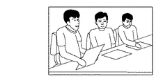
図2は上記図1に示したビデオカメラ付きビデオ会議用ディスプレイ装置、会議机、会議出席者の様子を側面から観た場合の会議レイアウト例を示す側面図、図3は上記図1に示したビデオカメラ付きビデオ会議用ディスプレイ装置、会議机、会議出席者の様子を上面から観た場合の会議のレイアウト例を示す上面図、図4は上記図2及び図3に示したビデオ会議の例における、上記図1に示したビデオカメラ付きビデオ会議用ディスプレイ装置により送出された画像の受信表示例を示す説明図である。
【0084】
図5は上記図1に示したビデオカメラ付きビデオ会議用ディスプレイ装置における第1のビデオカメラ3の撮影画像のイメージ例を示す説明図、図6は上記図1に示したビデオカメラ付きビデオ会議用ディスプレイ装置における第2のビデオカメラ4の撮影画像のイメージ例を示す説明図である。
【0085】
上記図1〜図3において、ディスプレイ本体1は、例えばプラズマディスプレイ装置(以下ディスプレイ装置)であり、装置中央部には、プラズマディスプレイのデバイスの画面2(以下画面2)が配置され、画面2の周辺のいわゆる額縁の左側に第1のビデオカメラ3、画面2の周辺のいわゆる額縁の右側に第2のビデオカメラ4が備えられている。ここで、第1のビデオカメラ3は、3が本体、3aはレンズ部である。同様に、第2のビデオカメラ4は、4が本体、4aはレンズ部である。
【0086】
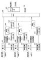
図7は本発明の第1の実施の形態に係るビデオカメラ付きビデオ会議用ディスプレイシステムの構成を示すブロック図である。本発明の第1の実施の形態のビデオカメラ付きビデオ会議用ディスプレイシステムは、ディスプレイ2、第1のビデオカメラ3、第2のビデオカメラ4、画像合成部10、マイクロフォン11、スピーカ12を有するディスプレイ本体1、ビデオ会議端末13、コーデック14、伝送回線15、マイクロフォン101、ビデオカメラ102、ディスプレイ103、スピーカ104、ビデオ会議端末105、コーデック106、伝送回線107を備えている。各部の機能は動作と共に後述する。
【0087】
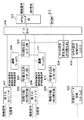
図8は本発明の第1の実施の形態に係るビデオカメラ付きビデオ会議用ディスプレイシステムの画像合成部10の詳細構成を示すブロック図である。本発明の第1の実施の形態のビデオカメラ付きビデオ会議用ディスプレイシステムの画像合成部10は、第1のカラーデコーダ301、同期分離回路及びクロック発生部302、メモリ書き込みコントロール部303、第1の画像フレームメモリ(1)304、メモリ読み出しコントロール部305、データセレクタ306、NTSCエンコーダ部307、第2のカラーデコーダ308、同期分離回路及びクロック発生部309、メモリ書き込みコントロール部310、第2の画像フレームメモリ(2)311、ROM312を備えている。各部の機能は動作と共に後述する。
【0088】
図23は本発明の各実施形態に係るプログラム及び関連データが記憶媒体から装置に供給される概念例を示す説明図である。プログラム及び関連データは、フロッピディスクやCD−ROM等の記憶媒体231をコンピュータ等の装置232に装備された記憶媒体ドライブ挿入口233に挿入することで供給される。その後、プログラム及び関連データを記憶媒体231から一旦ハードディスクにインストールしハードディスクからRAMにロードするか、或いはハードディスクにインストールせずに直接RAMにロードすることで、プログラム及び関連データを実行することが可能となる。
【0089】
この場合、本発明の各実施形態に係るビデオカメラ付きビデオ会議用ディスプレイシステムにおいてプログラムを実行する場合は、例えば上記図23に示したような手順で本システムの各装置にプログラム及び関連データを供給するか、或いは本システムの各装置に予めプログラム及び関連データを格納しておくことで、プログラム実行が可能となる。
【0090】
図22は本発明の各実施形態に係るプログラム及び関連データを記憶した記憶媒体の記憶内容の構成例を示す説明図である。記憶媒体は、例えばボリューム情報221、ディレクトリ情報222、プログラム実行ファイル223、プログラム関連データファイル224等の記憶内容で構成される。プログラムは、各実施形態の動作手順に基づきプログラムコード化されたものである。
【0091】
尚、本発明の特許請求の範囲と本発明の各実施形態との対応関係は下記の通りである。第1の撮像装置は第1のビデオカメラ3に対応し、第2の撮像装置は第2のビデオカメラ4に対応し、表示装置はディスプレイ2に対応し、画像合成手段は画像合成部10に対応し、画像信号入力手段は映像信号入力端子201に対応する。
【0092】
上記図1〜図3に示した画面2の左右の第1のビデオカメラ3及び第2のビデオカメラ4において、図3に示すように、第1のビデオカメラ3のレンズ部3aの光軸を法線Aとして示すと、法線Aと画面(スクリーン)2の左右を結ぶ線上X−X’との成す角度をθ1とすると、本実施形態の場合おおよそθ1≒45度である。第2のビデオカメラ4のレンズ部4aの光軸を法線Bとして示すと、法線Bと画面(スクリーン)2の左右を結ぶ線上X−X’との成す角度をθ2とすると、本実施形態の場合おおよそθ2≒45度である。
【0093】
以上の第1のビデオカメラ3の光軸設定において、図3に示す第1のビデオカメラ3のレンズ部3a及び図示せずとも、当然、内部撮像素子に関しても、上記それぞれの光軸上に対してしかるべき角度に配置される。第1のビデオカメラ3は、図3記載の出席者(1)、(2)、(3)を被写体として捉える角度イ、ロの範囲で撮像する。
【0094】
同様に、第2のビデオカメラ4の光軸設定において、図3に示す第2のビデオカメラ4のレンズ部4a及び図示せずとも、当然、内部撮像素子に関しても、上記それぞれの光軸上に対してしかるべき角度に配置される。第2のビデオカメラ4は、図3記載の出席者(4)、(5)、(6)を被写体として捉える角度ハ、ニの範囲で撮像する。
【0095】
尚、図2に示す側面からの図において、第1のビデオカメラ3のレンズ部3aからの光軸は設置面に対して略水平であり、画面2の上下方向の面Y−Y’に対しての角度θ3は約90度である。第1のビデオカメラ3の高さは上述のように移動可能であり、出席者(1)、(2)、(3)の顔の高さに設定される。
【0096】
同様に、図示せずとも、第2のビデオカメラ4のレンズ部4aからの光軸は設置面に対して略水平であり、画面2の上下方向の面Y−Y’に対しての角度θ3は約90度である。第2のビデオカメラ4の高さは上述のように移動可能であり、出席者(4)、(5)、(6)の顔の高さに設定される。
【0097】
また、第1のビデオカメラ3及び第2のビデオカメラ4はチルト可変可能であり、同様に、第1のビデオカメラ3及び第2のビデオカメラ4はパンニング方向にも可変可能であり、以上のようなカメラの高さ、チルト、パンニングの機能により、第1のビデオカメラ3と第2のビデオカメラ4の撮像エリアを設定し、会議の状況を撮像する。尚、カメラの高さ、チルト、パンニングの機能は電動式であってもよいし、また、カメラの高さ、チルト、パンニングの機能は電動式で受像側または送信側の何れか或いは第三の地点により制御することも可能であり、それにより操作性は向上する。
【0098】
以上による場合の第1のビデオカメラ3及び第2のビデオカメラ4のそれぞれが撮像する画像を図5、図6に示す。図5は第1のビデオカメラ3の撮像画像であり、図6は第2のビデオカメラ4の撮像画像である。第1のビデオカメラ3の撮像画像出力と第2のビデオカメラ4の撮像画像出力は、それぞれ本実施形態においては、輝度信号と色信号に分離されたNTSC(National Television System Commitee)ビデオ信号として出力され、図7における画像合成部10に供給される。
【0099】
図7の回路ブロックダイヤグラムの画像合成部10において、第1のビデオカメラ3及び第2のビデオカメラ4による撮像画像は各々縮小合成され、ビデオ会議端末13に送られる。図8に上記図7の回路ブロックダイヤグラムの画像合成部10の更に詳しい内容を示す。
【0100】
図8において、第1のカラーデコーダ301は、NTSC信号を復調するものであり、第1のビデオカメラ3からの映像信号をA/D変換するA/Dコンバータ(不図示)、該A/Dコンバータのデジタル信号をフィルタリングするデジタルフィルタ(不図示)を介してデジタル輝度信号を抽出し、また、デジタルバンドパスフィルタ(不図示)により平行変調された色信号を抽出し、該色信号に関しては色復調段により色復調を行い、デ・マトリクス部(不図示)にて輝度信号と色復調信号によりデジタル化された赤、緑、青の3原色信号を得る。
【0101】
上記デジタル化された赤、緑、青の3原色信号は、データセレクタ306に供給され、また同時に、第1の画像フレームメモリ304のデータバスにも接続される。第1の画像フレームメモリ304のデータバスは、本実施形態においては双方向のインターフェースである。第1のカラーデコーダ301、第1の画像フレームメモリ304の上記データバスに接続するインターフェースは、3ステートであり、詳述せずとも、メモリ書き込みコントロール部303、メモリ読み出しコントロール部305より適宜制御されるものである。第2のカラーデコーダ308、第2の画像フレームメモリ311においても同様である。
【0102】
第1の画像フレームメモリ304は、本実施形態においてはマルチポート型メモリを使用しており、書き込みと読み出しのタイミングは非同期で動作可能となる。その他の例えば画像フレームメモリLSIや、DRAM、SRAM等の汎用メモリにおいても、しかるべきタイミング及び接続により、書き込みと読み出しは同様に実現できることは勿論である。
【0103】
第1の画像フレームメモリ304の書き込みアドレスは、第1のメモリをAとしてA0からA76799番地までで、この数は水平320ドット、垂直240ドットの画素に相当する。尚、本実施形態においては、各ドットにつき、各赤、緑、青に対応し各々の階調を各6bitを割り当て、合計18bitのデータ幅を与える。
【0104】
一方、第1のカラーデコーダ301より同期分離回路及びクロック発生部302に、コンポジット同期信号と、第1のカラーデコーダ301から出力される赤、緑、青の3原色信号のデータレートに同じ周波数の基本クロックが供給される。本実施形態においては、第1のカラーデコーダ301は、有効表示期間において水平640ドット、垂直480ドット(ライン)の解像度に対応した出力レートを持つ。
【0105】
同期分離回路及びクロック発生部302により、水平同期信号と垂直同期信号を得て、データがメモリ書き込みコントロール部303に供給される。同様に、同期分離回路及びクロック発生部302により、第1のカラーデコーダ301から出力される赤、緑、青の3原色信号のデータレートの半分の周波数のクロックが後段のメモリ書き込みコントロール部303に供給される。
【0106】
メモリ書き込みコントロール部303において、第1の画像フレームメモリ304の第1のメモリの書き込みアドレスをA0からA76799番地まで、第1のカラーデコーダ301から出力される赤、緑、青の3原色信号のデータレートの半分の周波数で書き込みを行うことにより、第1のビデオカメラ3の出力画像を、水平方向で1画素おきの、水平320ドット、垂直方向にも1ラインおきの垂直240ラインの画素データが、第1の画像フレームメモリ304に逐次書き込まれていく。
【0107】
ここで、第1のビデオカメラ3の出力信号は、NTSC方式に準じているため、インターレース走査方式であるが、上記有効表示期間に関して奇数フィールド、偶数フィールドの順に1フレーム分をストアしていく。また、線順次走査(プログレッシブ)方式の場合は、そのまま1フレーム分を書き込めばよい。どちらの走査方式でも、余分に帰線期間のビデオデータをストアしても、アドレスさせ明確であれば、なんら問題はない。
【0108】
同様に、第2のビデオカメラ4の出力映像信号は、第2のカラーデコーダ308に入力される。データレート、解像度等は、上記第1のカラーデコーダ301と同じである。更に、同期分離回路及びクロック発生部309、メモリ書き込みコントロール部310に関しても、それぞれ第1のビデオカメラ3の信号処理と同様である。
【0109】
第2のカラーデコーダ308において復調されデジタル化された赤、緑、青の3原色信号はデータセレクタ306に供給される。また同時に、第2の画像フレームメモリ311のデータバスにも接続される。第2の画像フレームメモリ311のデータバスも、本実施形態においては、双方向のインターフェースであり、構成等は第1の画像フレームメモリ304と同様のものである。
【0110】
第2の画像フレームメモリ311の書き込みアドレスは、第2のメモリをBとしてB0からB76799番地までで、この数は水平320ドット、垂直240ドットの画素に相当する。尚、本実施形態においては、各ドットにつき、各赤、緑、青に対応し各々の階調を各6bitを割り当て、合計18bitのデータ幅を与える。
【0111】
一方、第2のカラーデコーダ308より同期分離回路及びクロック発生部309に、コンポジット同期信号と、第2のカラーデコーダ308から出力される赤、緑、青の3原色信号のデータレートに同じ周波数の基本クロックが供給される。本実施形態においては、第2のカラーデコーダ308は、有効表示期間において水平640ドット、垂直480ドット(ライン)の解像度に対応した出力レートを持つ。
【0112】
同期分離回路及びクロック発生部309により、水平同期信号と垂直同期信号を得て、データがメモリ書き込みコントロール部310に供給される。同様に、同期分離回路及びクロック発生部309により、第2のカラーデコーダ308から出力される赤、緑、青の3原色信号のデータレートの半分の周波数のクロックが後段のメモリ書き込みコントロール部310に供給される。
【0113】
メモリ書き込みコントロール部310において、第2の画像フレームメモリ311の書き込みアドレスをB0からB76799番地まで、第2のカラーデコーダ308から出力される赤、緑、青の3原色信号のデータレートの半分の周波数で書き込みを行うことにより、第2のビデオカメラ4の出力画像を、水平方向で1画素おきの、水平320ドット、垂直方向にも1ラインおきの垂直240ラインの画素データが、第2の画像フレームメモリ311に逐次書き込まれていく。尚、飛び越し走査または線順次走査方式に関しての対応は、上記第1のビデオカメラ3の場合と同様である。
【0114】
上記第1の画像フレームメモリ304と第2の画像フレームメモリ311のアドレスは、割り当て画素数以上にアドレスを増加させて、各ビデオカメラ3、4に関する情報を記録させてもよい。
【0115】
以上の動作により、上記第1の画像フレームメモリ304と第2の画像フレームメモリ311には、上記第1のビデオカメラ3と第2のビデオカメラ4の映像が各フレーム毎に、決められたアドレスに順次書き込まれる。
【0116】
次に、図9に記載のように、先ずメモリ読み出しコントロール部305により、第1の画像フレームメモリ304と第2の画像フレームメモリ311を読み出す。読み出しタイミングは、本実施形態においては、NTSC方式に準じて、水平640ドット、垂直480ラインの有効画素を想定して、垂直帰線期間、水平帰線期間を挟みながら順次読み出される。
【0117】
ここで、読み出しは、1垂直期間の前半の120ラインは、ダミーの例えば青色のデータまたは黒色のデータまたは灰色のデータ等、任意の色データを出力データとする。このダミーデータは、データセレクタ306の3つ目の入力に接続された、例えばROM(リードオンリメモリ)312から得る。ROM312には、予め決められたデータ値を書き込んでおく。ROM312は、電気的書き換え可能なROM(EEPROM)や、RAMに図示せずとも、マイクロコンピュータより、例えば装置の電源投入直後等に、予め決められたデータ値を書き込むことでも実現可能である。
【0118】
同様に、上記読み出しにおける、垂直帰線期間、水平帰線期間の黒レベル或いはセットアップレベルは、ROM312の別アドレスとして予めストアしておいて、上記読み出しの、垂直帰線期間、水平帰線期間に読み出される。
【0119】
次に、後半の121(241)ラインより、水平方向に320画素分として、第1の画像フレームメモリ304の第1ラインの1ライン分の320画素を読み出す。続けて、水平方向に321画素から640画素分まで、第2の画像フレームメモリ311の第1ラインの1ライン分の320画素を読み出す。
【0120】
以上の動作で、横640画素分の画像データが読み出され、該画像データの前半は第1の画像フレームメモリ304に保持された画像の第1ラインであり、後半は第2の画像フレームメモリ311に保持された画像の第1ラインがデータとして読み出される。
【0121】
同様に、122(242)ラインにおいて、水平期間の前半の320画素分として、第1の画像フレームメモリ304の第2ラインの1ライン分の304画素のデータを読み出す。続けて、上記読み出しの122ラインの後半の320画素分として、第2の画像フレームメモリ311の第2ラインの1ライン分の320画素を読み出す。
【0122】
以上のように順次、第3のライン、第4のラインという順序で読み出し、水平期間の前半において第1の画像フレームメモリ304、後半において第2の画像フレームメモリ311を読み出して、読み出し画像の第239ラインの後半の320画素を、第2の画像フレームメモリ311の120ラインの320画素を、続けて、読み出し画像の第240ラインの前半の320画素を、第1の画像フレームメモリ304の120ラインの320画素を、読み出し画像の第240ラインまで読み出す。
【0123】
次に、読み出し画像の偶数フィールドとして、上記奇数フィールドの読み出しに準じて、垂直帰線期間を挟んで241ラインから360ラインまで、ダミーの例えば青色のデータまたは黒色のデータまたは灰色のデータ等、任意の色データを出力データとする。このダミーデータは、上記奇数フィールド同様、データセレクタ306の3つ目の入力に接続された、例えばROM(リードオンリメモリ)312から得る。
【0124】
次の361ラインからは、上記奇数フィールドのフィールドメモリの読み出しと逆の順序、つまり、読み出し画像の361ラインの640画素のうち前半の320画素はROM312より得られるダミーのデータを、直前のライン同様に読み出す。361ラインの後半の320画素は、第2の画像フレームメモリ311の241ラインの320画素を読み出す。次の読み出しラインである362ラインの前半の320画素に関して、第1の画像フレームメモリ304の241ラインの320画素の読み出しを行う。続けて、第2の画像フレームメモリ311の242ラインの320画素を読み出す。
【0125】
以上のように交互に第1の画像フレームメモリ304と第2の画像フレームメモリ311を読み出し、読み出し画像の偶数フィールドの240ラインの前半の320画素は、第1の画像フレームメモリ304の240ラインの320画素を、偶数フィールドの240ラインの後半の320画素は、第2の画像フレームメモリ311の240ラインの320画素を読み出し、その後、垂直帰線期間に関し、ROM312の第2のデータである黒信号またはセットアップ信号を読み出し、次のフレームの読み出しに移る。
【0126】
上述したように、交互に第1の画像フレームメモリ304と、第2の画像フレームメモリ311と、ROM(読み出し専用メモリ)312とを、メモリ読み出しコントロール部305からの読み出し制御信号による制御と、データセレクタ306により、それぞれ対応するメモリをセレクトして、NTSCエンコーダ部307に入力する。
【0127】
NTSCエンコーダ部307は、赤、緑、青のデジタル色信号の入力を備え、データセレクタ306の出力デジタル信号の各色に対応して入力される。NTSCエンコーダ部307は、上記メモリから読み出された赤、緑、青のデジタル色信号を、図示せずとも、デジタルマトリクス、デジタルエンコーダ等の処理により、デジタルNTSC信号を得る。該NTSC信号は、同期信号を付加した輝度信号と直角2相平衡変調されたクロマ信号の所謂YCセパレート信号で、それぞれD/A変換され出力される。
【0128】
尚、上記第1のカラーデコーダ301、第2のカラーデコーダ308の構成は様々考えられ、アナログベースで復調し、その後、赤、緑、青の色信号の段階で、3つのA/DコンバータによりA/D変換して、第1の画像フレームメモリ304、第2の画像フレームメモリ311及びデータセレクタ306に供給しても、目的は達せられる。
【0129】
また、NTSCエンコーダ部307も上記の例とは異なり、入力されたデジタル信号を先にA/D変換して、アナログの赤、緑、青信号を得て、該アナログ色信号をマトリクス変換、直角2相平衡変調、同期信号付加の手段を経て、アナログのNTSC信号を出力する構成でも成り立つことは勿論である。
【0130】
NTSCエンコーダ部307のNTSC信号出力は、上記図7の本実施形態の全体のブロックダイアグラムにおいて、ビデオ会議端末13に供給される。ビデオ会議端末13においては、マイクロフォン11からの音声信号、ディスプレイ本体1への受信ビデオ信号、スピーカ12への受信音声信号の双方向の伝送切り換えを行っており、画像合成部10からの合成画像信号はマイクロフォン11よりの音声信号と合成され、次段のコーデック14に供給される。
【0131】
コーデック14にて伝送信号として圧縮変調され、受信信号においては復号解凍化され、送出においては伝送回線15に送出される。この場合に、一般的なビデオ会議用伝送信号圧縮形式として、ITU(International Telecommunication Union) Hシリーズ規格で、例えばH.320、H.323、H.324などがあり、それらの少なくとも一つに適合すると共に会議システムとも互換性を持つことが好ましい。
【0132】
伝送回線15は、その後、通信回線として、一般的にはISDN(Integrated Service Digital Network)回線等、或いはその他の有線または無線、光通信、衛星通信回線等を、単独に或いは複数組み合わせた通信媒体を介して、本実施形態においては伝送回線107に接続され、コーデック106に供給され、復号化され、ビデオ会議端末105に供給される。ビデオ会議端末105にて音声信号が復調増幅され、スピーカ104に出力される。また、ビデオ会議端末105から映像信号が復調され、ディスプレイ103に供給される。ディスプレイ103には、画像合成部10にて合成された状態の映像信号が表示される。
【0133】
図4にディスプレイ103に表示される画像のイメージを示す。図4に示すように、表示画像の左には第1のビデオカメラ3により撮像された映像、表示画像の右には第2のビデオカメラ4により撮像された映像が表示される。上述のように、送出側の第1のビデオカメラ3及び第2のビデオカメラ4をそれぞれ角度を設定し、第1のビデオカメラ3及び第2のビデオカメラ4の出力映像を合成し、伝送することにより、遠隔地の会議出席者が自然に向かい合うイメージで、良好に表示可能となるものである。
【0134】
尚、本実施形態の説明では、受像側のディスプレイ103は、特にビデオカメラ102のみの記載であるが、勿論、双方会議のディスプレイにおけるビデオカメラに関しては、本発明の特徴であるディスプレイの両側に上記請求項記載のカメラ光軸に関しての角度を持った2つのビデオカメラを具備することが、双方の会議の自然な状況を得るために望ましい。
【0135】
本発明の第1の実施の形態において、第1のビデオカメラ3及び第2のビデオカメラ4の出力をデジタルビデオのシリアルインターフェースまたはパラレルインターフェースとしても、本実施形態は実現できる。この場合、例えばシリアルインターフェースとしてはP1394やUSB(Universal Serial Bus)で、それらは一般的にアイソクロナスによるパケット転送方式により転送するのが画像の転送に適している。また、この場合、本実施形態の具体的には画像合成部10において、シリアル画像データをそれぞれフレーム画像データとして上記の画像フレームメモリに書き込む。読み出しは、上述のように第1のビデオカメラ3の画像が左の画像として、第2のビデオカメラ4の画像が右の画像として読み出される。
【0136】
次に、例えばシリアルインターフェースとしてはRS422で転送する。この場合、本実施形態の具体的には画像合成部10において、シリアル画像データをそれぞれフレーム画像データとして上記の画像フレームメモリに書き込む。画像合成部10においてA/D変換処理が省略できるため、画質劣化が軽減され、またコスト的にも有利である。読み出しは、上述のように第1のビデオカメラ3の画像が左の画像として、第2のビデオカメラ4の画像が右の画像として読み出され、ビデオ会議端末13に供給される。
【0137】
以上のカメラ手段及び画像処理においてはNTSC方式で説明したが、PAL(Phase Alternating by Line)方式、SECAM(Sequential Couleur a Memoire)方式、HDTV(High Density Television)方式等、或いはコンピュータのビデオグラフィックスフォーマット(例えばVGA(Video Graphics Array)、SVGA(Super Video Graphics Array)、XGA(Extended Graphics Array)等)においても基本的考え方は同一である。
【0138】
また、カラーの信号形式としては、NTSCのようなコンポジットカラービデオ信号や、Y、U、Vなどの色差信号形式、赤、緑、青の3原色信号形式でも、それぞれの信号処理過程においてデコード、エンコード、マトリクス、デマトリクス処理により実現は可能である。
【0139】
また、メモリに書き込み/読み出しを行う画像データは、コンポジットカラービデオ信号を直接デジタイズして、或いは輝度信号とクロマ信号に関してそれぞれデジタイズして、同様の書き込み/読み出し処理を行っても実現できることは勿論である。但し、コンポジットカラービデオ信号やクロマ信号をデジタイズする場合は、サブキャリア信号の周波数の2倍以上でサンプリングするのが望ましい。
【0140】
また、ビデオ会議端末13においては、デジタル信号入力として、内部処理を全てデジタル処理にすることにより、画像合成部10のD/A変換手段が省略できる。
【0141】
以上説明したように、本発明の第1の実施の形態によれば、会議用ディスプレイの両側に会議用のビデオカメラを具備し、ビデオカメラの撮影方向を互いの光軸が交わる所定の角度に設定し、複数の会議出席者を横からの撮影を回避するようにして、ビデオカメラの2つの映像を伝送し、受像側にあっては自然に2つの映像が並んで表示され、会議出席者の顔の表示がより良好な画角にて表示されるようにしたものである。
【0142】
即ち、会議用ディスプレイの両側にそれぞれ所定の角度の光軸を持つ2つのビデオカメラを具備し、ビデオカメラの2つの画像を画像合成手段により合成してから伝送するか、或いはビデオカメラの2つの画像を伝送してから画像合成し、会議用ディスプレイに向かって右のカメラの映像を表示画像の右に、左のカメラの映像を表示画像の左に表示する。これにより、ビデオ会議で用いる特に大型ディスプレイにおいて会議を行う場合、多くの出席者の顔の表情を良好に撮影、伝送、表示が可能なように構成することで、遠隔地の会議出席者が自然に向かい合うイメージで会議ディスプレイに画像を表示可能となり、効果的なビデオ会議が可能となるという効果を奏する。
【0143】
[第2の実施の形態]
上述した本発明の第1の実施の形態においては、上記図7の画像合成部10にて、第1のビデオカメラ3の画像と第2のビデオカメラ4の画像を合成した場合の残りの領域、つまり上記図8のメモリ読み出しコントロール部305に制御された読み取り画像の奇数フィールドの有効走査期間の第1ラインから120ラインの前半320画素期間と、偶数フィールド有効走査期間の第1ラインから120ラインの後半320画素期間において、ブランクの例えば青色のデータまたは黒色のデータまたは灰色のデータ等、任意の色データをROM312より供給して均一画像を表示したが、本発明の第2の実施の形態においては、外部より第3の映像を或いはキャラクタ等の映像を表示するようにしたものである。以下に本発明の第2の実施の形態について説明を行う。
【0144】
図10は本発明の第2の実施の形態に係るビデオカメラ付きビデオ会議用ディスプレイシステムの構成を示すブロック図である。本発明の第2の実施の形態のビデオカメラ付きビデオ会議用ディスプレイシステムは、ディスプレイ2、第1のビデオカメラ3、第2のビデオカメラ4、画像合成部10、マイクロフォン11、スピーカ12、映像信号入力端子(外部画像入力端子)201を有するディスプレイ本体1、ビデオ会議端末13、コーデック14、伝送回線15、マイクロフォン101、ビデオカメラ102、ディスプレイ103、スピーカ104、ビデオ会議端末105、コーデック106、伝送回線107を備えている。
【0145】
図10において、映像信号入力端子(外部画像入力端子)201は、第3の映像を入力する端子である。映像信号入力端子201には、例えばビデオテープレコーダ装置(以下VTR)のビデオ信号を接続して、該VTRのビデオ信号を入力し、画像合成部10に供給する。
【0146】
図11は本発明の第2の実施の形態に係るビデオカメラ付きビデオ会議用ディスプレイシステムの画像合成部10の詳細構成を示すブロック図である。本発明の第2の実施の形態のビデオカメラ付きビデオ会議用ディスプレイシステムの画像合成部10は、第1のカラーデコーダ301、同期分離回路及びクロック発生部302、メモリ書き込みコントロール部303、第1の画像フレームメモリ304、メモリ読み出しコントロール部305、データセレクタ306、NTSCエンコーダ部307、第2のカラーデコーダ308、同期分離回路及びクロック発生部309、メモリ書き込みコントロール部310、第2の画像フレームメモリ311、ROM312、第3のカラーデコーダ313、同期分離回路及びクロック発生部314、メモリ書き込みコントロール部315、第3の画像フレームメモリ316を備えている。
【0147】
図11において、第2の実施の形態は、上記第1の実施の形態の図8の構成の他に、第3のカラーデコーダ313、同期分離回路及びクロック発生部314、メモリ書き込みコントロール部315、第3の画像フレームメモリ316を備えるものである。尚、データセレクタ306は、入力を4系統として、第3の映像のセレクトを処理する。
【0148】
上記映像信号入力端子201から入力された第3の外部位映像信号は、第3のカラーデコーダ313に入力され、上記同様、赤、緑、青のデジタル映像信号に復調される。本実施形態においては、有効表示画面の水平方向に640画素のデータレートで出力される。同期分離回路及びクロック発生部314においては、水平同期信号と、垂直同期信号、フレーム信号、第3のカラーデコーダ313の出力映像信号のデータレートに対応したクロック信号が出力され、メモリ書き込みコントロール部315に供給される。
【0149】
メモリ書き込みコントロール部315からは、第3の画像フレームメモリ316の書き込み制御信号が出力される。第3の画像フレームメモリ316は、第1及び第2の画像フレームメモリ304、311と同様のマルチポートメモリを使用する。上記第1の実施の形態で述べたように、他の種類のRAMであっても、しかるべきタイミングにて駆動すれば問題はない。但し、第3の画像フレームメモリ316においては、垂直方向には1フレームあたり240ラインの容量を持ち、水平方向においては320画素分の容量を備える。
【0150】
次に、第1の画像フレームメモリ304、第2の画像フレームメモリ311、第3の画像フレームメモリ316は、それぞれ上記第1の実施の形態同様に、水平方向320画素、垂直方向240ライン分のフレーム画像を逐次書き込む。
【0151】
次に、メモリ読み出しコントロール部305において、第1の画像フレームメモリ304と第2の画像フレームメモリ311を読み出す。読み出しタイミングは、本実施形態においては、NTSC方式に準じて水平640ドット、垂直480ラインの有効画素を想定して、垂直帰線期間、水平帰線期間を挟みながら順次読み出される。
【0152】
ここで、読み出しは、奇数フィールドの1垂直期間の前半の120ラインは、第3の画像フレームメモリ316を読み出す。水平方向には320画素を読み出し、残りの320画素は上記第1の実施の形態同様に、ダミーの例えば青色のデータまたは黒色のデータまたは灰色のデータ等、任意の色データを出力データとする。このダミーデータは、データセレクタ306の3つ目の入力に接続された、例えばROM(リードオンリメモリ)312から得る。ROM312に関しては上記第1の実施の形態同様である。同様に、上記読み出しにおける垂直帰線期間、水平帰線期間の黒レベル或いはセットアップレベルは、ROM312の別アドレスとして予めストアしておいて、上記読み出しの垂直帰線期間、水平帰線期間に読み出される。
【0153】
以上のように、メモリ読み出しコントロール部305によるフレームメモリ読み出しの読み出し画面の上半分の左側に上記第3の画像を読み出し、次に、後半の121(241)ラインより、上記第1の実施の形態同様に、水平方向に320画素分として第1の画像フレームメモリ304の第1ラインの1ライン分の320画素を読み出す。続けて、水平方向に321画素から640画素分まで、第2の画像フレームメモリ311の第1ラインの1ライン分の320画素を読み出す。
【0154】
以上の動作で、横640画素分の画像データが読み出され、該画像データの前半は第1の画像フレームメモリ304に保持された画像の第1ラインであり、後半は第2の画像フレームメモリ311に保持された画像の第1ラインがデータとして読み出される。同様に、122(242)ラインにおいて、水平期間の前半の320画素分として、第1の画像フレームメモリ304の第2ラインの1ライン分の320画素のデータを読み出す。続けて、上記読み出しの122ラインの後半の320画素分として、第2の画像フレームメモリ311の第2ラインの1ライン分の320画素を読み出す。
【0155】
以上のように、順次第3のライン、第4のラインという順序で読み出し、水平期間の前半において第1の画像フレームメモリ304、後半において第2の画像フレームメモリ311を読み出して、読み出し画像の第239ラインの後半の320画素を、第2の画像フレームメモリ311の120ラインの320画素を、続けて、読み出し画像の第239ラインの前半の320画素を、第1の画像フレームメモリ304の120ラインの320画素を読み出し、画像の第240ラインまで読み出す。
【0156】
次に、読み出し画像の偶数フィールドとして、上記奇数フィールドの読み出しに準じて、垂直帰線期間を挟んで偶数フィールドの1(241)ラインから120(360)ラインまで、第3の画像フレームメモリ316を読み出す。インターレースのため、読み出し画像のタイミングの、奇数フィールド、有効表示画面の第1ラインは画面中央から始まり、この半分の水平期間はROM312から得られるダミー画像を、次の第2ラインの前半320画素は第3の画像フレームメモリ316の121ラインの320画素を読み出す。以降同様に、水平読み出し期間後半の320画素はROM312から得られるダミー画像、水平期間の前半は第3の画像フレームメモリ316を読み出す。
【0157】
次に、奇数フィールドの121(361)ラインからは、上記奇数フィールドのフィールドメモリの読み出しと逆の順序、つまり、読み出し画像の361ラインの640画素のうち、前半の320画素はROM312より得られるダミーのデータを直前のライン同様に読み出す。361ラインの後半の320画素は第2の画像フレームメモリ311の241ラインの320画素を読み出す。次の読み出しラインである362ラインの前半の320画素に関して、第1の画像フレームメモリ304の241ラインの320画素の読み出しを行う。続けて、第2の画像フレームメモリ311の242ラインの320画素を読み出す。
【0158】
以上のように交互に第1の画像フレームメモリ304と第2の画像フレームメモリ311を読み出し、読み出し画像の偶数フィールドの240ラインの前半320画素は、第1の画像フレームメモリ304の240ラインの320画素を、上記偶数フィールドの240ラインの後半の320画素は、第2の画像フレームメモリ311の240ラインの320画素を読み出し、その後、垂直帰線期間を、ROM312の第2のデータである黒信号またはセットアップ信号を読み出し、次のフレームの読み出しに移る。
【0159】
上述したように、交互に第3の画像フレームメモリ316と、第1の画像フレームメモリ304と、第2の画像フレームメモリ311と、ROM(読み出し専用メモリ)312とを、メモリ読み出しコントロール部305からの読み出し制御信号による制御と、データセレクタ306により、それぞれ対応するメモリをセレクトして、以降の処理を上記第1の実施の形態同様にNTSC方式に準じた変調を行い、後段の図10のビデオ会議端末13に供給し、上記第1の実施の形態同様にコーデック14及び伝送回線15を介して会議相手に対して伝送する。
【0160】
コーデック14にて伝送信号として圧縮変調され、受信信号においては復号解凍化され、送出においては伝送回線15に送出される。この場合に、一般的なビデオ会議用伝送信号圧縮形式として、ITU Hシリーズ規格で、例えばH.320、H323、H324などがあり、それらの少なくとも一つに適合すると共に会議システムとも互換性を持つことが好ましい。
【0161】
以上の処理においては、伝送される画像の4分割の第2象限に、上記映像信号入力端子(外部画像入力端子)201に入力された第3の画像が表示され、同画面の第3象限(画面下半分の左)に第1のビデオカメラ3の映像が、第4象限(画面下半分の右)に第2のビデオカメラの映像がそれぞれ表示可能となるものである。
【0162】
本発明の第2の実施の形態においても、上記第1の実施の形態同様に、第1のビデオカメラ3、第2のビデオカメラ4、及び第3のビデオ信号の信号出力を、デジタルビデオのシリアルインターフェースまたはパラレルインターフェースとしても、本実施形態は実現できる。この場合、上記第1実施形態記載の例えばシリアルインターフェースとしてはP1394やUSBで、それらは一般的にアイソクロナスによるパケット転送方式により転送するのが画像の転送に適している。また、この場合、上記第1実施形態の具体的には画像合成部10において、シリアル画像データをそれぞれフレーム画像データとして上記の画像フレームメモリに書き込む。読み出しは、上述のように第1のビデオカメラ3の画像が左の画像として、第2のビデオカメラ4の画像が右の画像として読み出される。
【0163】
次に、例えばシリアルインターフェースとしてはRS422で転送する。この場合、上記第1実施形態の具体的には画像合成部10において、シリアル画像データをそれぞれフレーム画像データとして上記の画像フレームメモリに書き込む。画像合成部10においてA/D変換処理が省略できるため、画質劣化が軽減され、またコスト的にも有利である。読み出しは、上述のように第1のビデオカメラ3の画像が左の画像として、第2のビデオカメラ4の画像が右の画像として読み出され、ビデオ会議端末13に供給される。
【0164】
以上のカメラ手段及び画像処理においてはNTSC方式で説明したが、PAL方式、SECAM方式、HDTV方式等、或いはコンピュータのビデオグラフィックスフォーマット(例えばVGA、SVGA、XGA等)においても基本的考え方は同一である。
【0165】
また、カラーの信号形式としては、NTSCのようなコンポジットカラービデオ信号や、Y、U、Vなどの色差信号形式、赤、緑、青の3原色信号形式でも、それぞれの信号処理過程においてデコード、エンコード、マトリクス、デマトリクス処理により実現は可能である。
【0166】
また、ビデオ会議端末13においては、デジタル信号入力として、内部処理を全てデジタル処理にすることにより、画像合成部10のD/A変換手段が省略できる。
【0167】
以上説明したように、本発明の第2の実施の形態によれば、上記第1の実施の形態と同様に、ビデオ会議で用いる特に大型ディスプレイにおいて会議を行う場合、多くの出席者の顔の表情を良好に撮影、伝送、表示が可能なように構成することで、遠隔地の会議出席者が自然に向かい合うイメージで会議ディスプレイに画像を表示可能となり、効果的なビデオ会議が可能となるという効果を奏する。
【0168】
[第3の実施の形態]
上述した本発明の第1の実施の形態及び第2の実施の形態記載の本発明のビデオカメラ付きディスプレイにおいて、第1のビデオカメラ3と第2のビデオカメラ4の画像を、上記実施形態の如く、第1のビデオカメラ3の画像を画面左に、第2のビデオカメラ4の画像を画面右に表示した場合に、本発明の第3の実施の形態では、画面の空いたエリアに或いは上記画像と重畳してキャラクタ情報を表示するようにしたものである。
【0169】
図12は本発明の第3の実施の形態に係るビデオカメラ付きビデオ会議用ディスプレイシステムの構成を示すブロック図である。本発明の第3の実施の形態のビデオカメラ付きビデオ会議用ディスプレイシステムは、ディスプレイ2、第1のビデオカメラ3、第2のビデオカメラ4、画像合成部10、マイクロフォン11、スピーカ12、外部キャラクタ制御端子501を有するディスプレイ本体1、ビデオ会議端末13、コーデック14、伝送回線15、マイクロフォン101、ビデオカメラ102、ディスプレイ103、スピーカ104、ビデオ会議端末105、コーデック106、伝送回線107を備えている。
【0170】
図13は本発明の第3の実施の形態に係るビデオカメラ付きビデオ会議用ディスプレイシステムの画像合成部10の詳細構成を示すブロック図である。本発明の第3の実施の形態のビデオカメラ付きビデオ会議用ディスプレイシステムの画像合成部10は、第1のカラーデコーダ301、同期分離回路及びクロック発生部302、メモリ書き込みコントロール部303、第1の画像フレームメモリ304、メモリ読み出しコントロール部305、データセレクタ306、NTSCエンコーダ部307、第2のカラーデコーダ308、同期分離回路及びクロック発生部309、メモリ書き込みコントロール部310、第2の画像フレームメモリ311、ROM312、外部コンピュータ接続インターフェース502、キャラクタ表示制御マイクロコントローラ503、キャラクタ信号発生部(OSD信号発生部)504を備えている。
【0171】
図12において、外部キャラクタ制御端子501に、例えばパーソナルコンピュータ(不図示)の制御信号線を接続し、図13の外部コンピュータ接続インターフェース502に接続される。次に、外部コンピュータ接続インターフェース502を介してキャラクタ表示制御マイクロコントローラ503に接続される。
【0172】
キャラクタ表示制御マイクロコントローラ503において、上記外部接続のコンピュータからのキャラクタ表示制御コマンドを送り込み、キャラクタ信号発生部504を制御する。キャラクタ信号発生部504からは、上記コマンドに従ったキャラクタ信号をデータセレクタ306を介して、上記フレームメモリ読み出し画像の空きスペースに或いは直接重ね表示を行い、後段のNTSCエンコーダ部307にて変調処理を行い、図12のビデオ会議端末13に送られ、上記第1及び第2の実施の形態同様に、コーデック14及び伝送回線15を介して会議相手に送出されるものである。
【0173】
コーデック14にて伝送信号として圧縮変調され、受信信号においては復号解凍化され、送出においては伝送回線15に送出される。この場合に、一般的なビデオ会議用伝送信号圧縮形式として、ITU Hシリーズ規格で、例えばH.320、H323、H324などがあり、それらの少なくとも一つに適合すると共に会議システムとも互換性を持つことが好ましい。
【0174】
以上の第3の実施の形態の処理により、例えば図14の表示例に示すように、上記第1及び第2の実施の形態の如く、第1のビデオカメラ3の画像を画面左に、第2のビデオカメラ4の画像を画面右に表示した場合に、該表示画面の空いたエリアに或いは上記画像と重畳してキャラクタ情報を表示して、会議相手に伝送可能としたものである。
【0175】
本発明の第3の実施の形態において、第1のビデオカメラ3及び第2のビデオカメラ4の出力を、デジタルビデオのシリアルインターフェースまたはパラレルインターフェースとしても、本実施形態は実現できる。この場合、例えばシリアルインターフェースとしてはP1394やUSBで、それらは一般的にアイソクロナスによるパケット転送方式により転送するのが画像の転送に適している。また、この場合、上記第1及び第2実施形態の具体的には画像合成部10において、シリアル画像データをそれぞれフレーム画像データとして上記の画像フレームメモリに書き込む。読み出しは、上述のように第1のビデオカメラ3の画像が左の画像として、第2のビデオカメラ4の画像が右の画像として読み出される。
【0176】
次に、例えばシリアルインターフェースとしてはRS422で転送する。この場合、上記第1及び第2実施形態の具体的には画像合成部10において、シリアル画像データをそれぞれフレーム画像データとして上記の画像フレームメモリに書き込む。画像合成部10においてA/D変換処理が省略できるため、画質劣化が軽減され、またコスト的にも有利である。読み出しは、上述のように第1のビデオカメラ3の画像が左の画像として、第2のビデオカメラ4の画像が右の画像として読み出され、ビデオ会議端末13に供給される。
【0177】
以上のカメラ手段及び画像処理においてはNTSC方式で説明したが、PAL方式、SECAM方式、HDTV方式等、或いはコンピュータのビデオグラフィックスフォーマット(例えばVGA、SVGA、XGA等)においても基本的考え方は同一である。
【0178】
また、カラーの信号形式としては、NTSCのようなコンポジットカラービデオ信号や、Y、U、Vなどの色差信号形式、赤、緑、青の3原色信号形式でも、それぞれの信号処理過程においてデコード、エンコード、マトリクス、デマトリクス処理により実現は可能である。
【0179】
また、ビデオ会議端末13においては、デジタル信号入力として、内部処理を全てデジタル処理にすることにより、画像合成部10のD/A変換手段が省略できる。
【0180】
以上説明したように、本発明の第3の実施の形態によれば、上記第1及び第2の実施の形態と同様に、ビデオ会議で用いる特に大型ディスプレイにおいて会議を行う場合、多くの出席者の顔の表情を良好に撮影、伝送、表示が可能なように構成することで、遠隔地の会議出席者が自然に向かい合うイメージで会議ディスプレイに画像を表示可能となり、効果的なビデオ会議が可能となるという効果を奏する。
【0181】
[第4の実施の形態]
上述した本発明の第1の実施の形態及び第2の実施の形態記載の本発明のビデオカメラ付きディスプレイにおいて、第1のビデオカメラ3と第2のビデオカメラ4の画像を、本発明の第4の実施の形態においては、それぞれ画像圧縮処理して第1の圧縮画像と第2の圧縮画像として、例えばH.320の伝送プロトコル上の映像符号データとして同時に転送するものである。
【0182】
図15は本発明の第4の実施の形態に係るビデオカメラ付きビデオ会議用ディスプレイシステムの構成を示すブロック図である。本発明の第4の実施の形態のビデオカメラ付きビデオ会議用ディスプレイシステムは、ディスプレイ2、第1のビデオカメラ3、第2のビデオカメラ4、画像合成部10、マイクロフォン11、スピーカ12、外部キャラクタ制御端子501を有するディスプレイ本体1、ビデオ会議端末13、コーデック14、伝送回線15、マイクロフォン101、ビデオカメラ102、ディスプレイ103、スピーカ104、ビデオ会議端末105、コーデック106、伝送回線107を備えている。
【0183】
図17は本発明の第4の実施の形態に係るビデオカメラ付きビデオ会議用ディスプレイシステムの画像合成部10の詳細構成を示すブロック図である。本発明の第4の実施の形態のビデオカメラ付きビデオ会議用ディスプレイシステムの画像合成部10は、第1の画像復号部401、同期分離回路及びクロック発生部402、メモリ書き込みコントロール部303、第1の画像フレームメモリ304、メモリ読み出しコントロール部305、データセレクタ306、NTSCエンコーダ部307、第2の画像復号部408、同期分離回路及びクロック発生部409、メモリ書き込みコントロール部310、第2の画像フレームメモリ311、ROM312、データ復号部602、キャラクタ表示制御マイクロコントローラ503、キャラクタ信号発生部(OSD信号発生部)504を備えている。
【0184】
図15において、第1のビデオカメラ3と第2のビデオカメラ4の画像信号は、それぞれビデオ会議端末13に供給される。ビデオ会議端末13において、第1のビデオカメラ3と第2のビデオカメラ4の画像信号はそれぞれ、例えばITU−TにおけるH.261画像符号化規格に基づき画像圧縮符号化される。同様に音声についても、G711、G722、G728等の音声符号化規格に準じて音声圧縮符号化される。
【0185】
これらの圧縮符号化データは、図16に示すような通信プロトコル構成を持つ。これらは図15にあってはコーデック14にて行われ、伝送回線15に送出される。伝送回線15は、上記第1の実施の形態同様に、その後、通信回線として、一般的にはISDN回線等或いはその他の有線または無線、光通信、衛星通信回線等を、単独に或いは複数組み合わせた通信媒体を介して、本実施形態においては伝送回線107に接続され、コーデック106に供給される。
【0186】
コーデック106においては、例えば上記送出のH.320の伝送プロトコルに準じて、図15に示す2つの第1及び第2のビデオカメラ3、4の画像信号である上記第1の圧縮画像と第2の圧縮画像を、他の音声データ、付加データ等と共に分離抽出して復号化して、ビデオ会議端末105に供給する。或いは、ビデオ会議端末105の中において、それぞれの圧縮符号化信号を復号化して、画像信号に関しては、上記第1の圧縮画像からの復調信号は画面の左に、更に、上記第2の圧縮画像からの復調信号は画面の右に、画像合成する。ここで、画像合成部10は、図17に示すように、上記第1、第2及び第3の実施形態に示すような画像合成部10に準ずる。
【0187】
図17において、コーデック部106より得られる画像データ1及び画像データ2の、画像圧縮されたH.261の画像データは、それぞれ第1の画像復号部401と第2の画像復号部408に供給され、復号化され、例えば第1の画像復号部401から出力された赤、緑、青の色信号は、第1の画像フレームメモリ304と、データセレクタ306に接続されたデータバスに供給される。
【0188】
尚、第1の画像復号部401より基本同期信号を抽出して、同期分離回路及びクロック発生部402よりメモリ書き込みコントロール部303に同期信号とクロック信号を供給する。メモリ書き込みコントロール部303においては、第1の画像フレームメモリ304の書き込み制御信号を該画像フレームメモリ304に供給する。
【0189】
第1の画像フレームメモリ304は、第1の画像復号部401からの画像信号を順次フレーム毎に、決められたアドレスに書き込む。同様に、第1の画像復号部401から出力された赤、緑、青の色信号は、第2の画像フレームメモリ311とデータセレクタ306に供給される。
【0190】
尚、第2の画像復号部408より基本同期信号を抽出して、同期分離回路及びクロック発生部409よりメモリ書き込みコントロール部310に同期信号とクロック信号を供給する。メモリ書き込みコントロール部310においては、第2の画像フレームメモリ311の書き込み制御信号を該画像フレームメモリ311に供給する。
【0191】
第2の画像フレームメモリ311は、第2の画像復号部408からの画像信号を順次フレーム毎に、決められたアドレスに書き込む。
【0192】
以上の動作により、2つの画像フレームメモリ304と311に、上記第1のカメラ画像と第2のカメラ画像が逐次書き込まれる。
【0193】
尚、データ復号部602には、上記画像通信プロトコル上に同時に組み込まれて伝送されたITU−Tにて規格化された、例えばT.120やH.281などのフォーマットに基づいたキャラクタ等の情報が供給され、復号化される。該データは、キャラクタ表示制御マイクロコントローラ503を介してキャラクタ信号発生部504に供給され、データセレクタ306に接続される。
【0194】
次に、メモリ読み出しコントロール部305において、特定の圧縮フォーマット固有の水平及び垂直の画素数やインターレース或いはノンインターレース等の規定があるが、ここでは上記第1の実施の形態同様に、水平方向640ドット、垂直240ラインとして、先ず奇数フィールドを、同様に続いて水平方向640ドット、垂直方向240ラインとして偶数フィールドに準じた、例えば毎秒30フレームのインターレース画像信号として、上記第1の実施の形態の読み出しタイミングと同様に、第1の画像フレームメモリ304と第2の画像フレームメモリ311を読み出し、図17に示す如く画像データ1より得られる第1のビデオカメラ3による画像を画面の左に、画像データ2より得られる第2のビデオカメラ4による画像を画面の右に合成して表示する。
【0195】
また、キャラクタ信号発生部504より出力されるキャラクタ信号は、メモリ読み出しコントロール部305より得られる同期信号及びクロック信号に基づき、データセレクタ306を介してNTSCエンコーダ部307により変調され、ディスプレイ103に供給され、図18に示す如くディスプレイ103の表示画面においては、上記2つの画像以外の、図示するCエリアにキャラクタ情報を表示するものである。
【0196】
以上の処理により、上記第1の実施の形態及び第3の実施の形態に示すような効果が得られると同時に、上記第1の圧縮画像と第2の圧縮画像を抽出して復調した画像信号は、データとして2つに分離されており、表示画面の任意の位置に設定して、配置できる。
【0197】
図19はその例であり、例えば基本画像がコンピュータグラフィックスフォーマットのXGAの場合、図20に示すように、その左右両方の下端角の領域に表示して、残りの領域にはコンピュータの映像等を表示してもよい。この場合、本実施形態における電気的構成においては、上記2つの画像フレームメモリ304、311及びキャラクタ信号発生部504の読み出し周波数及びタイミングを適合化することにより、実施可能である。この場合、データセレクタ306のブランキング用ROMにおいても、メモリ読み出しコントロール部305に同期して適正タイミングにて機能することは勿論である。
【0198】
以上説明したように、本発明の第4の実施の形態によれば、上記第1、第2及び第3の実施の形態と同様に、ビデオ会議で用いる特に大型ディスプレイにおいて会議を行う場合、多くの出席者の顔の表情を良好に撮影、伝送、表示が可能なように構成することで、遠隔地の会議出席者が自然に向かい合うイメージで会議ディスプレイに画像を表示可能となり、効果的なビデオ会議が可能となるという効果を奏する。
【0199】
[第5の実施の形態]
上述した本発明の第1〜第4の実施の形態において、上記第1のビデオカメラ3と第2のビデオカメラ4の画像信号の出力が、一部或いは全部、光学的に、画像合成部10或いはパーソナルコンピュータ(PC)のインターフェースと接続され伝送されるようにしても、同様の実現は可能である。
【0200】
[第6の実施の形態]
上述した本発明の第1〜第5の実施の形態において、上記第1のビデオカメラ3と第2のビデオカメラ4の画像信号の出力が、一部或いは全部、電波の使用による無線通信手段により、画像合成部10或いはパーソナルコンピュータ(PC)のインターフェースと接続され伝送されるようにしても、同様の実現は可能である。
【0201】
[第7の実施の形態]
上述した本発明の第1〜第6の実施の形態において、ディスプレイは、プラズマディスプレイデバイス(PDP)の他に、陰極線管(CRT)によるディスプレイ、液晶或いは動揺画素ミラー2次元配列ディスプレイデバイス等による、ライトバルブリアプロジェクションディスプレイ、上記と同様のディスプレイによるライトバルブフロントプロジェクションディスプレイのスクリーン画面、液晶表示フラットディスプレイデバイス、ルミネッセンスフラットディスプレイデバイス、LEDアレイフラットディスプレイデバイス、FED(Field Emission Display)、SED(Surface condition Electron Emitter Display)の何れであっても、勿論同様の効果が得られるものである。
【0202】
[他の実施の形態]
上述した本発明の第1〜第4の実施の形態においては、2つのビデオ会議端末を伝送回線で接続し、会議出席者の顔の表情を撮影、伝送、表示する場合を例に上げたが、本発明はこれに限定されるものではなく、3つ以上のビデオ会議端末を伝送回線で接続し、会議出席者の顔の表情を撮影、伝送、表示する場合にも適用可能である。
【0203】
また、上述した本発明の第1〜第4の実施の形態においては、ビデオ会議用途の場合を例に上げたが、本発明はこれに限定されるものではなく、コミュニケーション用途にも適用可能である。
【0204】
尚、本発明は、複数の機器から構成されるシステムに適用しても、1つの機器からなる装置に適用してもよい。上述した実施形態の機能を実現するソフトウエアのプログラムコードを記憶した記憶媒体を、システム或いは装置に供給し、そのシステム或いは装置のコンピュータ(またはCPUやMPU)が記憶媒体等の媒体に格納されたプログラムコードを読み出し実行することによっても、達成されることは言うまでもない。
【0205】
この場合、記憶媒体等の媒体から読み出されたプログラムコード自体が上述した実施形態の機能を実現することになり、そのプログラムコードを記憶した記憶媒体等の媒体は本発明を構成することになる。プログラムコードを供給するための記憶媒体等の媒体としては、例えば、フロッピディスク、ハードディスク、光ディスク、光磁気ディスク、CD−ROM、CD−R、磁気テープ、不揮発性のメモリカード、ROM、或いはダウンロードなどを用いることができる。
【0206】
また、コンピュータが読み出したプログラムコードを実行することにより、上述した実施形態の機能が実現されるだけでなく、そのプログラムコードの指示に基づき、コンピュータ上で稼働しているOSなどが実際の処理の一部または全部を行い、その処理によって上述した実施形態の機能が実現される場合も含まれることは言うまでもない。
【0207】
更に、記憶媒体等の媒体から読出されたプログラムコードが、コンピュータに挿入された機能拡張ボードやコンピュータに接続された機能拡張ユニットに備わるメモリに書込まれた後、そのプログラムコードの指示に基づき、その機能拡張ボードや機能拡張ユニットに備わるCPUなどが実際の処理の一部または全部を行い、その処理によって上述した実施形態の機能が実現される場合も含まれることは言うまでもない。
【0208】
【発明の効果】
以上説明したように、本発明によれば、第1の撮像装置の光軸と表示画面の底辺に平行な該表示画面の左右の両端を結ぶ直線X−X’との成す角度を45度に設定するとともに、第1の撮像装置における光軸を中心線とした同一水平面上の左右方向の撮像範囲を、ビデオ会議の出席者を被写体として捉える角度の範囲に設定し、第2の撮像装置の光軸と表示画面の底辺に平行な該表示画面の左右の両端を結ぶ直線X−X’との成す角度を45度に設定するとともに、第2の撮像装置における光軸を中心線とした同一水平面上の左右方向の撮像範囲を、ビデオ会議の出席者を被写体として捉える角度の範囲に設定し、第1の撮像装置及び第2の撮像装置の高さを、表示画面の下辺から上辺までの間で移動可能に構成するとともに、第1の撮像装置及び第2の撮像装置を、表示装置に対して着脱可能に構成し、第1の撮像装置及び第2の撮像装置の撮影方向を、互いの光軸が交わる所定の角度に設定可能とすることにより、即ち、ビデオ会議で用いる特に大型ディスプレイにおいて会議を行う場合、多くの出席者の顔の表情を良好に撮影、伝送、表示が可能なように構成することで、遠隔地の会議出席者が自然に向かい合うイメージで会議ディスプレイに画像を表示可能となり、効果的なビデオ会議が可能となるという効果を奏する。
【図面の簡単な説明】
【図1】本発明の第1の実施の形態に係るビデオカメラ付きビデオ会議用ディスプレイ装置の構成を示す正面図である。
【図2】本発明の第1の実施の形態に係るビデオカメラ付きビデオ会議用ディスプレイ装置を使用した会議のレイアウト例を示す側面図である。
【図3】本発明の第1の実施の形態に係るビデオカメラ付きビデオ会議用ディスプレイ装置を使用した会議のレイアウト例を示す上面図である。
【図4】本発明の第1の実施の形態に係るビデオカメラ付きビデオ会議用ディスプレイ装置により送出された画像の受像画の表示例を示す説明図である。
【図5】本発明の第1の実施の形態に係るビデオカメラ付きビデオ会議用ディスプレイ装置における第1のビデオカメラの撮影画像のイメージ例を示す説明図である。
【図6】本発明の第1の実施の形態に係るビデオカメラ付きビデオ会議用ディスプレイ装置における第2のビデオカメラの撮影画像のイメージ例を示す説明図である。
【図7】本発明の第1の実施の形態に係るビデオカメラ付きビデオ会議用ディスプレイシステムの構成を示すブロック図である。
【図8】本発明の第1の実施の形態に係るビデオカメラ付きビデオ会議用ディスプレイシステムにおける画像合成部の詳細構成を示すブロック図である。
【図9】本発明の第1の実施の形態に係るビデオカメラ付きビデオ会議用ディスプレイシステムにおける画像フレームメモリ読み出しを示すタイミング図である。
【図10】本発明の第2の実施の形態に係るビデオカメラ付きビデオ会議用ディスプレイシステムの構成を示すブロック図である。
【図11】本発明の第2の実施の形態に係るビデオカメラ付きビデオ会議用ディスプレイシステムにおける画像合成部の詳細構成を示すブロック図である。
【図12】本発明の第3の実施の形態に係るビデオカメラ付きビデオ会議用ディスプレイシステムの構成を示すブロック図である。
【図13】本発明の第3の実施の形態に係るビデオカメラ付きビデオ会議用ディスプレイシステムにおける画像合成部の詳細構成を示すブロック図である。
【図14】本発明の第3の実施の形態に係る画像の例を示す説明図である。
【図15】本発明の第4の実施の形態に係るビデオカメラ付きビデオ会議用ディスプレイシステムの構成を示すブロック図である。
【図16】本発明の第4の実施の形態に係るビデオ会議用通信プロトコルの例を示す説明図である。
【図17】本発明の第4の実施の形態に係るビデオカメラ付きビデオ会議用ディスプレイシステムにおける画像合成部の詳細構成を示すブロック図である。
【図18】本発明の第4の実施の形態に係る受像画像表示例を示す説明図である。
【図19】本発明の第4の実施の形態に係る第2の受像画像表示例を示す説明図である。
【図20】本発明の第4の実施の形態に係る第3の受像画像表示例を示す説明図である。
【図21】本発明の第4の実施の形態に係る第4の受像画像表示例を示す説明図である。
【図22】本発明の第1〜第4の実施の形態に係るプログラム及び関連データを記憶した記憶媒体の記憶内容の構成例を示す説明図である。
【図23】本発明の第1〜第4の実施の形態に係るプログラム及び関連データが記憶媒体から装置に供給される概念例を示す説明図である。
【図24】従来例に係る会議用ディスプレイ、会議出席者、会議用テーブルの配置例を示す側面図である。
【図25】従来例に係る会議用ディスプレイ、会議出席者、会議用テーブルの配置例を示す上面図である。
【図26】従来例に係るビデオカメラが撮影したカメラ画像のイメージを示す説明図である。
【図27】従来例に係る会議用ディスプレイ、会議出席者、会議用テーブルの別の配置例を示す側面図である。
【図28】従来例に係る会議用ディスプレイ、会議出席者、会議用テーブルの別の配置例を示す上面図である。
【図29】従来例に係るビデオカメラが撮像した別のカメラ画像のイメージを示す説明図である。
【図30】従来例に係るビデオ会議用ディスプレイ、ビデオカメラ等の構成を示すブロック図である。
【符号の説明】
1 ディスプレイ本体
2 画面表示枠
3 第1のビデオカメラ
4 第2のビデオカメラ
10 画像合成部
11、101 マイクロフォン
12、104 スピーカ
13、105 ビデオ会議端末
14、106 コーデック
15、107 伝送回線[0001]
BACKGROUND OF THE INVENTION
The present invention relates to a video conference imaging / display device comprising a video conference display device with a video camera. In place More specifically, for example, in a video conference, video images of a plurality of conference attendees displayed on an image plane of a conversation partner display of a video conference camera corresponding to a large screen display are displayed on the conversation partner display. A video conferencing imaging / display device suitable for shooting the environment and image data. In place Related.
[0002]
[Prior art]
Conventionally, various systems for conducting video conferences in companies and the like have been proposed. FIGS. 24 to 26 show a first example of a conventional video conference display and camera system. FIG. 24 is a diagram of the conference display, the conference attendees, and the table surrounded by the conference attendants as viewed from the side. FIG. 25 is a view from the top. FIG. 26 is an image diagram of a camera image captured by the video camera in that case.
[0003]
As shown in FIGS. 24 and 25, a video camera used for a video conference or the like is conventionally placed on a pan head that can be swung or a video camera with a pan head is placed on a display. The pattern is photographed, the photographed image is transmitted to the conference partner via a wired or wireless individual or network line through compression or non-compression processing, and is displayed on the conference partner's display via an appropriate demodulation means. Had gone.
[0004]
27 to 29 show a second example of a conventional video conference display and camera system. FIG. 27 is a view of the conference display, the conference attendees, and the table surrounded by the conference attendants as viewed from the side. FIG. 28 is a view from the top. FIG. 29 is an image diagram of a camera image captured by the video camera in that case.
[0005]
As shown in FIGS. 27 and 28, conventional video cameras used for video conferencing and the like are installed under the front of the display and the like to photograph the pattern of the attendees of the conference, and wired or wireless individual or network to the conference partner The captured image is transmitted via a line or the like through compression or non-compression processing, and is displayed on the display of the conference partner via an appropriate demodulating means to hold a conference. In this case, on both or one of the display screens of the conference group, the video of the video camera of the conference partner and other images of the computer, for example, are switched or simultaneously displayed as a multi-screen.
[0006]
FIG. 30 is a block diagram showing the configuration of a system including a conventional video conference display, a video camera, and the like. The conventional system includes
[0007]
[Problems to be solved by the invention]
In recent years, displays such as those described above have increased the content of high-definition content such as SXGA and XGA (eXtended Graphics Array) as the display resolution of personal computers for display sources, and digital television for broadcasts on televisions. Accordingly, the display screen tends to increase in size in accordance with the trend toward higher definition.
[0008]
Particularly in recent years, displays of about 50 to 100 inches, high-vision monitors, and the like have been put into practical use as rear data projection apparatuses and plasma displays (PDPs). In many cases, such a display is introduced into a conference room, and the opportunity to convey the facial expressions of attendees to the conference partner via such a large display has increased.
[0009]
However, as shown in FIG. 24, FIG. 25, FIG. 27, and FIG. 28, if the video camera is simply installed on the display or below the display screen to capture the facial expressions of the attendees, For example, when the camera is installed on the display, the attendee's head is photographed as shown in the image of the camera image in FIG. 26, and the attendee's facial expressions such as eyes and mouth movements are sufficiently photographed. Can not.
[0010]
In addition, when a video camera is installed below the screen of the display as shown in FIGS. 27 and 28, the height of the video camera becomes lower with the increase in the size of the display. In general, as shown in FIGS. The height of the conference table that is laid out in front of the display. The image taken from such a position becomes an expression of the side of the attendees who are lined up on the conference table as shown in FIG. 29, and the attendee on the camera side gets in the way, in order. Some or all of the attendees in line are visible. Furthermore, there is a disadvantage that the vicinity of the waist of the presenter of the meeting described in front of the display is caught.
[0011]
The present invention has been made in view of the above-described points, and is configured so that facial expressions of many attendees can be photographed, transmitted, and displayed satisfactorily when a conference is performed particularly on a large display used in a video conference. As a result, remote conference attendees can display images on the conference display with images that face each other naturally, enabling an effective video conference imaging / display device. Place The purpose is to provide.
[0012]
To achieve the above objective, Book The invention Has a display screen Display device A first imaging device disposed outside the display screen range of the display device and on the left side toward the display screen, and outside the display screen range of the display device and on the right side toward the display screen. And an output of each of the first imaging device and the second imaging device. Video signal In the display device An imaging / display device for video conferencing that inputs and displays images, The angle formed between the optical axis of the first imaging device and a straight line XX ′ connecting the left and right ends of the display screen parallel to the bottom of the display screen is set to 45 degrees, and the first imaging device The horizontal imaging range on the same horizontal plane with the optical axis in the center line as the center line is set to an angle range in which video conference attendees are captured as subjects, and the optical axis of the second imaging device and the bottom of the display screen The angle formed by the straight line XX ′ connecting the left and right ends of the display screen parallel to the horizontal axis is set to 45 degrees, and the horizontal direction on the same horizontal plane with the optical axis as the center line in the second imaging device is set. The imaging range is set to an angle range that captures attendees of the video conference as subjects, and the height of the first imaging device and the second imaging device is moved from the lower side to the upper side of the display screen. The first imaging is possible and configured And the second imaging device are configured to be detachable from the display device, and the imaging directions of the first imaging device and the second imaging device are set to a predetermined angle at which the optical axes intersect each other. Set It is characterized by that.
[0013]
To achieve the above object, according to a second aspect of the present invention, the imaging device is a video camera, and the height of the imaging device is set between a lower side and an upper side of the display screen of the display device. It is characterized by that.
[0014]
In order to achieve the above object, the invention according to
[0015]
In order to achieve the above-mentioned object, the invention according to
[0016]
In order to achieve the above object, the invention according to
[0081]
DETAILED DESCRIPTION OF THE INVENTION
Hereinafter, embodiments of the present invention will be described in detail with reference to the drawings.
[0082]
[First Embodiment]
FIG. 1 is a front view showing a configuration of a video conference display device with a video camera according to a first embodiment of the present invention, and is a diagram best representing the features of the present invention. The video conferencing display device with a video camera according to the first embodiment of the present invention has a display screen frame (screen, display) 2 and a
[0083]
2 is a side view showing an example of a conference layout when viewing the video conference display device with a video camera, the conference desk, and the attendees of the conference shown in FIG. 1 from the side, and FIG. 3 shows the conference layout shown in FIG. FIG. 4 is a top view showing a layout example of a conference when a video conference display device with a video camera, a conference desk, and attendees are viewed from above, and FIG. 4 is an example of the video conference shown in FIG. 2 and FIG. FIG. 3 is an explanatory diagram showing an example of receiving and displaying an image sent by the video conference display device with a video camera shown in FIG. 1.
[0084]
FIG. 5 is an explanatory diagram showing an example of an image taken by the
[0085]
1 to 3, the display
[0086]
FIG. 7 is a block diagram showing the configuration of the video conference display system with a video camera according to the first embodiment of the present invention. The video conferencing display system with a video camera according to the first embodiment of the present invention includes a
[0087]
FIG. 8 is a block diagram showing a detailed configuration of the
[0088]
FIG. 23 is an explanatory diagram showing a conceptual example in which a program and related data according to each embodiment of the present invention are supplied from a storage medium to the apparatus. The program and related data are supplied by inserting a
[0089]
In this case, when the program is executed in the video conference display system with a video camera according to each embodiment of the present invention, for example, the program and related data are supplied to each device of the system according to the procedure shown in FIG. Alternatively, the program can be executed by storing the program and related data in advance in each device of the present system.
[0090]
FIG. 22 is an explanatory diagram showing a configuration example of storage contents of a storage medium storing a program and related data according to each embodiment of the present invention. The storage medium includes storage contents such as
[0091]
The correspondence between the claims of the present invention and the embodiments of the present invention is as follows. The first imaging device corresponds to the
[0092]
In the
[0093]
In the setting of the optical axis of the
[0094]
Similarly, in setting the optical axis of the
[0095]
2, the optical axis from the
[0096]
Similarly, although not shown, the optical axis from the
[0097]
The
[0098]
Images taken by the
[0099]
7, the images captured by the
[0100]
In FIG. 8, a
[0101]
The digitized red, green, and blue primary color signals are supplied to the
[0102]
In the present embodiment, the first
[0103]
The write address of the first
[0104]
On the other hand, the
[0105]
The synchronization separation circuit and
[0106]
In the memory
[0107]
Here, since the output signal of the
[0108]
Similarly, the output video signal of the
[0109]
The red, green, and blue three primary color signals demodulated and digitized by the
[0110]
The write address of the second
[0111]
On the other hand, the
[0112]
The synchronization separation circuit and
[0113]
In the memory write control unit 310, the write address of the second
[0114]
The addresses of the first
[0115]
Through the above operation, the first
[0116]
Next, as shown in FIG. 9, first, the memory read
[0117]
Here, reading is performed by using arbitrary color data such as blue data, black data, or gray data as output data for 120 lines in the first half of one vertical period. This dummy data is obtained from, for example, a ROM (Read Only Memory) 312 connected to the third input of the
[0118]
Similarly, the black level or set-up level in the vertical blanking period and horizontal blanking period in the readout is stored in advance as another address in the
[0119]
Next, 320 pixels corresponding to one line of the first line of the first
[0120]
With the above operation, image data for 640 pixels in the horizontal direction is read out, the first half of the image data is the first line of the image held in the first
[0121]
Similarly, in the 122 (242) line, the data of 304 pixels for one line of the second line of the first
[0122]
As described above, reading is performed sequentially in the order of the third line and the fourth line, and the first
[0123]
Next, as the even field of the read image, in accordance with the reading of the odd field, from the 241st line to the 360th line with the vertical blanking interval, any dummy data such as blue data, black data, gray data, etc. Is used as output data. This dummy data is obtained from, for example, a ROM (Read Only Memory) 312 connected to the third input of the
[0124]
From the next 361 line, the reverse order of the reading of the field memory of the odd field, that is, the first 320 pixels out of the 640 pixels of the read image 361, the dummy data obtained from the
[0125]
As described above, the first
[0126]
As described above, the first
[0127]
The
[0128]
Various configurations of the
[0129]
Also, unlike the above example, the
[0130]
The NTSC signal output of the
[0131]
The
[0132]
Thereafter, the
[0133]
FIG. 4 shows an image displayed on the
[0134]
In the description of the present embodiment, the
[0135]
In the first embodiment of the present invention, the present embodiment can also be realized by using outputs of the
[0136]
Next, for example, as a serial interface, data is transferred by RS422. In this case, specifically, in the
[0137]
The above-mentioned camera means and image processing have been described in the NTSC system, but the PAL (Phase Alternating by Line) system, the SECAM (Sequential Couleur a Memoire) system, the HDTV (High Density Television) system, or the video graphics format of the computer. The basic concept is the same in VGA (Video Graphics Array), SVGA (Super Video Graphics Array), XGA (Extended Graphics Array), and the like.
[0138]
As color signal formats, composite color video signals such as NTSC, color difference signal formats such as Y, U, and V, and three primary color signal formats of red, green, and blue are decoded in each signal processing process. Realization is possible by encoding, matrix, and dematrix processing.
[0139]
Also, the image data to be written / read to / from the memory can be realized by directly digitizing the composite color video signal or digitizing the luminance signal and the chroma signal and performing the same writing / reading process. is there. However, when digitizing a composite color video signal or chroma signal, it is desirable to sample at a frequency that is at least twice the frequency of the subcarrier signal.
[0140]
Further, in the
[0141]
As described above, according to the first embodiment of the present invention, the video camera for conference is provided on both sides of the conference display, and the shooting direction of the video camera is set to a predetermined angle at which the optical axes intersect with each other. Set up to prevent multiple participants from taking pictures from the side, and transmit two images from the video camera. On the receiver side, the two images are displayed side by side naturally. The face is displayed with a better angle of view.
[0142]
That is, two video cameras each having a predetermined angle optical axis are provided on both sides of the conference display, and the two images of the video camera are transmitted after being combined by the image combining means. After the images are transmitted, the images are combined, and the right camera image is displayed on the right of the display image and the left camera image is displayed on the left of the display image toward the conference display. As a result, when a conference is performed on a large display used for video conferencing, it is possible to make it possible to capture, transmit and display the facial expressions of many attendees well so that remote conference attendees can naturally It is possible to display an image on the conference display with an image facing each other, and an effective video conference is possible.
[0143]
[Second Embodiment]
In the above-described first embodiment of the present invention, the remaining area when the image of the
[0144]
FIG. 10 is a block diagram showing a configuration of a video conference display system with a video camera according to the second embodiment of the present invention. The video conference display system with a video camera according to the second embodiment of the present invention includes a
[0145]
In FIG. 10, a video signal input terminal (external image input terminal) 201 is a terminal for inputting a third video. For example, a video signal of a video tape recorder device (hereinafter referred to as a VTR) is connected to the video
[0146]
FIG. 11 is a block diagram showing a detailed configuration of the
[0147]
11, in the second embodiment, in addition to the configuration of FIG. 8 of the first embodiment, a
[0148]
The third external video signal input from the video
[0149]
The memory
[0150]
Next, the first
[0151]
Next, the memory read
[0152]
Here, the reading is performed by reading the third
[0153]
As described above, the third image is read out on the left side of the upper half of the reading screen of the frame memory reading by the memory
[0154]
With the above operation, image data for 640 pixels in the horizontal direction is read out, the first half of the image data is the first line of the image held in the first
[0155]
As described above, the third line and the fourth line are sequentially read out in this order, the first
[0156]
Next, as the even field of the read image, the third
[0157]
Next, from the odd field 121 (361) line, the first 320 pixels out of the 640 pixels of the 361 line of the read image is a dummy obtained from the
[0158]
As described above, the first
[0159]
As described above, the third
[0160]
The
[0161]
In the above processing, the third image input to the video signal input terminal (external image input terminal) 201 is displayed in the second quadrant of the four-divided image to be transmitted, and the third quadrant ( The video of the
[0162]
Also in the second embodiment of the present invention, as in the first embodiment, the signal outputs of the
[0163]
Next, for example, as a serial interface, data is transferred by RS422. In this case, specifically, the
[0164]
The above camera means and image processing have been described in the NTSC system, but the basic concept is the same in the PAL system, SECAM system, HDTV system, etc., or in the video graphics format of a computer (eg, VGA, SVGA, XGA, etc.). is there.
[0165]
As color signal formats, composite color video signals such as NTSC, color difference signal formats such as Y, U, and V, and three primary color signal formats of red, green, and blue are decoded in each signal processing process. Realization is possible by encoding, matrix, and dematrix processing.
[0166]
Further, in the
[0167]
As described above, according to the second embodiment of the present invention, as in the first embodiment, when a conference is performed particularly on a large display used in a video conference, the faces of many attendees By configuring the facial expression so that it can be captured, transmitted, and displayed well, remote conference attendees can display images on the conference display as if they were facing each other naturally, enabling effective video conferencing. There is an effect.
[0168]
[Third Embodiment]
In the display with a video camera of the present invention described in the first embodiment and the second embodiment of the present invention, the images of the
[0169]
FIG. 12 is a block diagram showing a configuration of a video conference display system with a video camera according to the third embodiment of the present invention. The video conference display system with a video camera according to the third embodiment of the present invention includes a
[0170]
FIG. 13 is a block diagram showing a detailed configuration of the
[0171]
In FIG. 12, for example, a control signal line of a personal computer (not shown) is connected to the external
[0172]
The character
[0173]
The
[0174]
By the processing of the third embodiment described above, as shown in the display example of FIG. 14, for example, the image of the
[0175]
In the third embodiment of the present invention, the present embodiment can also be realized by using the outputs of the
[0176]
Next, for example, as a serial interface, data is transferred by RS422. In this case, specifically, in the first and second embodiments, the
[0177]
Although the above camera means and image processing have been described in the NTSC system, the basic concept is the same in the PAL system, SECAM system, HDTV system, etc., or in the video graphics format of a computer (eg, VGA, SVGA, XGA, etc.). is there.
[0178]
As color signal formats, composite color video signals such as NTSC, color difference signal formats such as Y, U, and V, and three primary color signal formats of red, green, and blue are decoded in each signal processing process. Realization is possible by encoding, matrix, and dematrix processing.
[0179]
Further, in the
[0180]
As described above, according to the third embodiment of the present invention, as in the first and second embodiments, a large number of participants are used when a conference is performed on a large display used for a video conference. By configuring the camera so that it can capture, transmit, and display the facial expression of a person's face, it is possible to display an image on the conference display with the image of a remote conference attendee facing the natural environment, enabling effective video conferencing. It has the effect of becoming.
[0181]
[Fourth Embodiment]
In the display with a video camera of the present invention described in the first embodiment and the second embodiment of the present invention, the images of the
[0182]
FIG. 15 is a block diagram showing a configuration of a video conference display system with a video camera according to the fourth embodiment of the present invention. The video conference display system with a video camera according to the fourth embodiment of the present invention includes a
[0183]
FIG. 17 is a block diagram showing a detailed configuration of the
[0184]
In FIG. 15, the image signals of the
[0185]
These compression-encoded data have a communication protocol configuration as shown in FIG. In FIG. 15, these are performed by the
[0186]
In the
[0187]
In FIG. 17,
[0188]
A basic synchronization signal is extracted from the first
[0189]
The first
[0190]
The basic synchronization signal is extracted from the second image decoding unit 408, and the synchronization signal and the clock signal are supplied from the synchronization separation circuit and
[0191]
The second
[0192]
With the above operation, the first camera image and the second camera image are sequentially written in the two
[0193]
The
[0194]
Next, in the memory read
[0195]
The character signal output from the character
[0196]
By the above processing, the effects as shown in the first embodiment and the third embodiment can be obtained, and at the same time, the image signal obtained by extracting and demodulating the first compressed image and the second compressed image. Is separated into two as data and can be set and arranged at an arbitrary position on the display screen.
[0197]
FIG. 19 shows an example. For example, when the basic image is an XGA of a computer graphics format, as shown in FIG. 20, it is displayed in the left and right lower corner areas, and the remaining area is a computer image or the like. May be displayed. In this case, the electrical configuration in the present embodiment can be implemented by adapting the read frequencies and timings of the two
[0198]
As described above, according to the fourth embodiment of the present invention, as in the first, second, and third embodiments, when a conference is performed particularly on a large display used in a video conference, many By making it possible to capture, transmit, and display the facial expressions of the attendees in a good location, it is possible to display images on the conference display with natural images facing remote conference attendees. There is an effect that a meeting becomes possible.
[0199]
[Fifth Embodiment]
In the first to fourth embodiments of the present invention described above, the output of the image signals of the
[0200]
[Sixth Embodiment]
In the first to fifth embodiments of the present invention described above, the output of the image signals of the
[0201]
[Seventh Embodiment]
In the first to sixth embodiments of the present invention described above, the display is not only a plasma display device (PDP) but also a display using a cathode ray tube (CRT), a liquid crystal or a oscillating pixel mirror two-dimensional array display device, etc. Light valve rear projection display, light valve front projection display screen screen, LCD display flat display device, luminescence flat display device, LED array flat display device, FED (Field Emission Display), SED (Surface condition Electron) Of course, the same effect can be obtained with any of (Emitter Display).
[0202]
[Other embodiments]
In the first to fourth embodiments of the present invention described above, the case where two video conference terminals are connected by a transmission line and the facial expressions of conference attendees are photographed, transmitted, and displayed has been taken as an example. The present invention is not limited to this, and can also be applied to a case where three or more video conference terminals are connected by a transmission line to capture, transmit, and display facial expressions of conference attendees.
[0203]
In the first to fourth embodiments of the present invention described above, the case of video conferencing is given as an example. However, the present invention is not limited to this and can be applied to communication. is there.
[0204]
The present invention may be applied to a system composed of a plurality of devices or an apparatus composed of a single device. A storage medium storing software program codes for realizing the functions of the above-described embodiments is supplied to a system or apparatus, and a computer (or CPU or MPU) of the system or apparatus is stored in a medium such as a storage medium. Needless to say, this can also be achieved by reading and executing the program code.
[0205]
In this case, the program code itself read from the medium such as a storage medium realizes the functions of the above-described embodiments, and the medium such as the storage medium storing the program code constitutes the present invention. . As a medium such as a storage medium for supplying the program code, for example, a floppy disk, a hard disk, an optical disk, a magneto-optical disk, a CD-ROM, a CD-R, a magnetic tape, a nonvolatile memory card, a ROM, a download, or the like Can be used.
[0206]
In addition, by executing the program code read by the computer, not only the functions of the above-described embodiments are realized, but also the OS running on the computer based on the instruction of the program code performs the actual processing. Needless to say, a case where the function of the above-described embodiment is realized by performing part or all of the processing is included.
[0207]
Furthermore, after the program code read from a medium such as a storage medium is written in a memory provided in a function expansion board inserted in the computer or a function expansion unit connected to the computer, based on the instruction of the program code, It goes without saying that the CPU of the function expansion board or function expansion unit performs part or all of the actual processing and the functions of the above-described embodiments are realized by the processing.
[0208]
【The invention's effect】
As explained above, according to the present invention, The angle formed by the optical axis of the first imaging device and the straight line XX ′ connecting the left and right ends of the display screen parallel to the bottom of the display screen is set to 45 degrees, and the optical axis in the first imaging device The horizontal imaging range on the same horizontal plane with the center line as the center line is set to an angle range that captures the attendees of the video conference as subjects, and the display is parallel to the optical axis of the second imaging device and the bottom of the display screen. The angle formed by the straight line XX ′ connecting the left and right ends of the screen is set to 45 degrees, and the imaging range in the horizontal direction on the same horizontal plane with the optical axis as the center line in the second imaging device is set as a video conference. And the height of the first imaging device and the second imaging device are configured to be movable from the lower side to the upper side of the display screen, The imaging device and the second imaging device are connected to the display device. Detachably configured, the imaging direction of the first imaging device and the second imaging device, can be set at a predetermined angle to each other of the optical axis intersect In other words, when a conference is performed on a large display used in a video conference, it is possible to capture, transmit, and display the facial expressions of many attendees well so that remote conference attendance is possible. It is possible to display an image on the conference display with an image that the person faces naturally, and an effective video conference is possible.
[Brief description of the drawings]
FIG. 1 is a front view showing a configuration of a video conference display device with a video camera according to a first embodiment of the present invention.
FIG. 2 is a side view showing a layout example of a conference using the video conference display device with a video camera according to the first embodiment of the present invention.
FIG. 3 is a top view showing a layout example of a conference using the video conference display device with a video camera according to the first embodiment of the present invention.
FIG. 4 is an explanatory diagram illustrating a display example of an image received by the video conference display device with a video camera according to the first embodiment of the present invention.
FIG. 5 is an explanatory diagram illustrating an example of an image captured by the first video camera in the video conference display device with a video camera according to the first embodiment of the present invention.
FIG. 6 is an explanatory diagram showing an example of a captured image of the second video camera in the video conference display device with a video camera according to the first embodiment of the present invention.
FIG. 7 is a block diagram showing a configuration of a video conference display system with a video camera according to the first embodiment of the present invention.
FIG. 8 is a block diagram showing a detailed configuration of an image composition unit in the video conference display system with a video camera according to the first embodiment of the present invention.
FIG. 9 is a timing chart showing image frame memory reading in the video conferencing display system with a video camera according to the first embodiment of the present invention.
FIG. 10 is a block diagram showing a configuration of a video conference display system with a video camera according to a second embodiment of the present invention.
FIG. 11 is a block diagram showing a detailed configuration of an image composition unit in a video conference display system with a video camera according to a second embodiment of the present invention.
FIG. 12 is a block diagram showing a configuration of a video conference display system with a video camera according to a third embodiment of the present invention.
FIG. 13 is a block diagram showing a detailed configuration of an image composition unit in a video conference display system with a video camera according to a third embodiment of the present invention.
FIG. 14 is an explanatory diagram illustrating an example of an image according to a third embodiment of the present invention.
FIG. 15 is a block diagram showing a configuration of a video conference display system with a video camera according to a fourth embodiment of the present invention.
FIG. 16 is an explanatory diagram showing an example of a video conference communication protocol according to the fourth embodiment of the present invention;
FIG. 17 is a block diagram showing a detailed configuration of an image composition unit in a video conference display system with a video camera according to a fourth embodiment of the present invention;
FIG. 18 is an explanatory diagram showing an example of an received image display according to the fourth embodiment of the present invention.
FIG. 19 is an explanatory diagram showing a second received image display example according to the fourth embodiment of the invention.
FIG. 20 is an explanatory diagram showing a third received image display example according to the fourth embodiment of the invention.
FIG. 21 is an explanatory diagram illustrating a fourth received image display example according to the fourth embodiment of the invention.
FIG. 22 is an explanatory diagram showing a configuration example of storage contents of a storage medium storing a program and related data according to the first to fourth embodiments of the present invention.
FIG. 23 is an explanatory diagram showing a conceptual example in which a program and related data according to the first to fourth embodiments of the present invention are supplied from a storage medium to an apparatus.
FIG. 24 is a side view showing an arrangement example of a conference display, conference attendees, and a conference table according to a conventional example.
FIG. 25 is a top view showing an arrangement example of a conference display, conference attendees, and a conference table according to a conventional example.
FIG. 26 is an explanatory diagram showing an image of a camera image taken by a video camera according to a conventional example.
FIG. 27 is a side view showing another arrangement example of a conference display, conference attendees, and a conference table according to a conventional example.
FIG. 28 is a top view showing another arrangement example of a conference display, conference attendees, and a conference table according to a conventional example.
FIG. 29 is an explanatory diagram showing an image of another camera image captured by a video camera according to a conventional example.
FIG. 30 is a block diagram illustrating a configuration of a video conference display, a video camera, and the like according to a conventional example.
[Explanation of symbols]
1 Display body
2 Screen display frame
3 First video camera
4 Second video camera
10 Image composition part
11, 101 Microphone
12, 104 Speaker
13, 105 Video conference terminal
14, 106 codec
15, 107 Transmission line
Claims (5)
前記第1の撮像装置の光軸と前記表示画面の底辺に平行な該表示画面の左右の両端を結ぶ直線X−X’との成す角度を45度に設定するとともに、前記第1の撮像装置における光軸を中心線とした同一水平面上の左右方向の撮像範囲を、ビデオ会議の出席者を被写体として捉える角度の範囲に設定し、
前記第2の撮像装置の光軸と前記表示画面の底辺に平行な該表示画面の左右の両端を結ぶ直線X−X’との成す角度を45度に設定するとともに、前記第2の撮像装置における光軸を中心線とした同一水平面上の左右方向の撮像範囲を、ビデオ会議の出席者を被写体として捉える角度の範囲に設定し、
前記第1の撮像装置及び前記第2の撮像装置の高さを、前記表示画面の下辺から上辺までの間で移動可能に構成するとともに、前記第1の撮像装置及び前記第2の撮像装置を、前記表示装置に対して着脱可能に構成し、
前記第1の撮像装置及び前記第2の撮像装置の撮影方向を、互いの光軸が交わる所定の角度に設定したことを特徴とするビデオ会議用撮像/表示装置。 A display device having a display screen; a first imaging device arranged outside the display screen range of the display device and on the left side of the display screen; and outside the display screen range of the display device and the display And a second imaging device arranged on the right side of the screen, and a video for displaying an image by inputting respective output video signals of the first imaging device and the second imaging device to the display device A conference imaging / display device,
The angle formed between the optical axis of the first imaging device and a straight line XX ′ connecting the left and right ends of the display screen parallel to the bottom of the display screen is set to 45 degrees, and the first imaging device Set the horizontal imaging range on the same horizontal plane with the optical axis at the center line as the range of angles that capture video conference attendees as subjects,
The angle formed by the optical axis of the second imaging device and a straight line XX ′ connecting the left and right ends of the display screen parallel to the bottom of the display screen is set to 45 degrees, and the second imaging device Set the horizontal imaging range on the same horizontal plane with the optical axis at the center line as the range of angles that capture video conference attendees as subjects,
The heights of the first imaging device and the second imaging device are configured to be movable from the lower side to the upper side of the display screen, and the first imaging device and the second imaging device are configured to be movable. , Configured to be detachable from the display device,
An image pickup / display device for video conference, wherein the shooting directions of the first image pickup device and the second image pickup device are set to a predetermined angle at which the optical axes intersect each other .
前記画像合成手段は、前記第1の撮像装置及び前記第2の撮像装置の出力映像信号と、外部から前記画像信号入力手段に入力された画像信号とを1つの画面として合成することを特徴とする請求項4に記載のビデオ会議用撮像/表示装置。Comprising image signal input means for inputting an image signal from the outside;
The image synthesizing means, the output video signal of the first imaging device and the second imaging device, and a benzalkonium be combined with the image signal input from the outside to the image signal input means as one screen 5. The video conference imaging / display device according to claim 4 ,
Priority Applications (1)
| Application Number | Priority Date | Filing Date | Title |
|---|---|---|---|
| JP2000168858A JP4623609B2 (en) | 2000-06-06 | 2000-06-06 | Imaging / display device for video conference |
Applications Claiming Priority (1)
| Application Number | Priority Date | Filing Date | Title |
|---|---|---|---|
| JP2000168858A JP4623609B2 (en) | 2000-06-06 | 2000-06-06 | Imaging / display device for video conference |
Publications (3)
| Publication Number | Publication Date |
|---|---|
| JP2001346178A JP2001346178A (en) | 2001-12-14 |
| JP2001346178A5 JP2001346178A5 (en) | 2007-07-19 |
| JP4623609B2 true JP4623609B2 (en) | 2011-02-02 |
Family
ID=18671807
Family Applications (1)
| Application Number | Title | Priority Date | Filing Date |
|---|---|---|---|
| JP2000168858A Expired - Fee Related JP4623609B2 (en) | 2000-06-06 | 2000-06-06 | Imaging / display device for video conference |
Country Status (1)
| Country | Link |
|---|---|
| JP (1) | JP4623609B2 (en) |
Families Citing this family (4)
| Publication number | Priority date | Publication date | Assignee | Title |
|---|---|---|---|---|
| JP5066277B1 (en) * | 2011-06-10 | 2012-11-07 | 株式会社東芝 | Television receiver |
| JP5106672B1 (en) * | 2011-10-03 | 2012-12-26 | 株式会社東芝 | Electronics |
| JP5567075B2 (en) * | 2012-08-06 | 2014-08-06 | 株式会社東芝 | Electronics |
| JP6745374B1 (en) * | 2019-03-29 | 2020-08-26 | 株式会社スノーピークビジネスソリューションズ | Remote communication device |
-
2000
- 2000-06-06 JP JP2000168858A patent/JP4623609B2/en not_active Expired - Fee Related
Also Published As
| Publication number | Publication date |
|---|---|
| JP2001346178A (en) | 2001-12-14 |
Similar Documents
| Publication | Publication Date | Title |
|---|---|---|
| US6211918B1 (en) | Video signal converter and television signal processing apparatus | |
| JP2012142977A (en) | Receiver | |
| KR100190250B1 (en) | Digital television set | |
| JPH0851600A (en) | Video signal converter | |
| JP4623609B2 (en) | Imaging / display device for video conference | |
| KR100532021B1 (en) | Method and system for single-chip integration of 3D Y/C comb filter and interlace-to-progressive converter | |
| JP3573724B2 (en) | Transmission system, transmission device, reception device, and transmission method, transmission method, reception method | |
| JP2863180B2 (en) | Video phone | |
| JP3300103B2 (en) | Still image transmitting device and still image receiving and displaying device | |
| JP3267180B2 (en) | Composite screen display device | |
| JP4212212B2 (en) | Image signal processing device | |
| JPH0759070A (en) | Display controller | |
| JP3363480B2 (en) | Two-screen display method | |
| JPH10174015A (en) | Double screen display device | |
| JPH0564184A (en) | Screen configuration system for video conference system | |
| JPH07131769A (en) | Picture communication terminal equipment | |
| JP2004297823A (en) | Signal transmission system | |
| JP4253058B2 (en) | Digital camera device | |
| JPH09168122A (en) | Video display device | |
| JPS6047792B2 (en) | 2-screen color television receiver | |
| JPS63263893A (en) | Television receiver | |
| JP2004153421A (en) | Camera video image processing system, camera video processing method, and imaging camera | |
| JPH0822052B2 (en) | MUSE-NTSC system converter | |
| JPH08149419A (en) | Still picture transmitting device | |
| JPH04189073A (en) | Picture quality adjustment device |
Legal Events
| Date | Code | Title | Description |
|---|---|---|---|
| RD03 | Notification of appointment of power of attorney |
Free format text: JAPANESE INTERMEDIATE CODE: A7423 Effective date: 20060324 |
|
| A521 | Request for written amendment filed |
Free format text: JAPANESE INTERMEDIATE CODE: A523 Effective date: 20070601 |
|
| A621 | Written request for application examination |
Free format text: JAPANESE INTERMEDIATE CODE: A621 Effective date: 20070601 |
|
| RD05 | Notification of revocation of power of attorney |
Free format text: JAPANESE INTERMEDIATE CODE: A7425 Effective date: 20070626 |
|
| A977 | Report on retrieval |
Free format text: JAPANESE INTERMEDIATE CODE: A971007 Effective date: 20100414 |
|
| A131 | Notification of reasons for refusal |
Free format text: JAPANESE INTERMEDIATE CODE: A131 Effective date: 20100420 |
|
| A521 | Request for written amendment filed |
Free format text: JAPANESE INTERMEDIATE CODE: A523 Effective date: 20100615 |
|
| TRDD | Decision of grant or rejection written | ||
| A01 | Written decision to grant a patent or to grant a registration (utility model) |
Free format text: JAPANESE INTERMEDIATE CODE: A01 Effective date: 20101028 |
|
| A01 | Written decision to grant a patent or to grant a registration (utility model) |
Free format text: JAPANESE INTERMEDIATE CODE: A01 |
|
| A61 | First payment of annual fees (during grant procedure) |
Free format text: JAPANESE INTERMEDIATE CODE: A61 Effective date: 20101029 |
|
| R150 | Certificate of patent or registration of utility model |
Free format text: JAPANESE INTERMEDIATE CODE: R150 |
|
| FPAY | Renewal fee payment (event date is renewal date of database) |
Free format text: PAYMENT UNTIL: 20131112 Year of fee payment: 3 |
|
| LAPS | Cancellation because of no payment of annual fees |