JP4621496B2 - Line scan ophthalmoscope - Google Patents
Line scan ophthalmoscope Download PDFInfo
- Publication number
- JP4621496B2 JP4621496B2 JP2004512595A JP2004512595A JP4621496B2 JP 4621496 B2 JP4621496 B2 JP 4621496B2 JP 2004512595 A JP2004512595 A JP 2004512595A JP 2004512595 A JP2004512595 A JP 2004512595A JP 4621496 B2 JP4621496 B2 JP 4621496B2
- Authority
- JP
- Japan
- Prior art keywords
- light
- line
- eye
- laser ophthalmoscope
- line scan
- Prior art date
- Legal status (The legal status is an assumption and is not a legal conclusion. Google has not performed a legal analysis and makes no representation as to the accuracy of the status listed.)
- Expired - Fee Related
Links
Images


Classifications
-
- A—HUMAN NECESSITIES
- A61—MEDICAL OR VETERINARY SCIENCE; HYGIENE
- A61B—DIAGNOSIS; SURGERY; IDENTIFICATION
- A61B3/00—Apparatus for testing the eyes; Instruments for examining the eyes
- A61B3/10—Objective types, i.e. instruments for examining the eyes independent of the patients' perceptions or reactions
- A61B3/1025—Objective types, i.e. instruments for examining the eyes independent of the patients' perceptions or reactions for confocal scanning
Landscapes
- Life Sciences & Earth Sciences (AREA)
- Health & Medical Sciences (AREA)
- Medical Informatics (AREA)
- Biophysics (AREA)
- Ophthalmology & Optometry (AREA)
- Engineering & Computer Science (AREA)
- Biomedical Technology (AREA)
- Heart & Thoracic Surgery (AREA)
- Physics & Mathematics (AREA)
- Molecular Biology (AREA)
- Surgery (AREA)
- Animal Behavior & Ethology (AREA)
- General Health & Medical Sciences (AREA)
- Public Health (AREA)
- Veterinary Medicine (AREA)
- Eye Examination Apparatus (AREA)
- Microscoopes, Condenser (AREA)
- Facsimile Heads (AREA)
Abstract
Description
(政府の権利)
本発明は、National Institutes of Health/National Eye Instituteによって認可された、契約番号1R43 EY11819−01A1の下で、政府の支持を得てなされた。政府は、本発明において特定の権利を有し得る。
(Government rights)
This invention was made with government support under Contract No. 1R43 EY11819-01A1, approved by the National Institutes of Health / National Eye Institute. The government may have certain rights in the invention.
(発明の分野)
本発明は、一般に、眼を試験するためのシステムおよび方法に関する。より具体的には、本発明は、眼を試験するために、スキャンされた光のラインを使用する、システムおよび方法に関する。
(Field of Invention)
The present invention relates generally to systems and methods for testing an eye. More specifically, the present invention relates to systems and methods that use scanned lines of light to test an eye.
(発明の背景)
基底部のイメージングは、眼科学において本質的な診断手順である。眼の基底部を試験するために有用な、先行技術の機器としては、直接的な検眼鏡および間接的な検眼鏡、細隙灯生体顕微鏡、ならびに基底部カメラが挙げられる。診断および治療の可能性を拡張した、相補的なツール(例えば、スキャンレーザー検眼鏡(SLO))が開発された。SLOは、眼の基底部およびその構造(脈絡血液、メラニン、および網膜色素)の、高いコントラストの画像を迅速かつ連続的に獲得するための、優れたツールである。これは、種々の可視波長およびNIR波長に適応するので、SLOは、加齢性黄斑変性(AMD)および糖尿病瀬網膜症のような疾患の研究および初期の診断のために、本質的に有用である。これらは、老人の失明の主要な原因である。SLOは、網膜の病理を特徴付けるため、ならびに血管障害、断層撮影法、視野測定、および一般的な精神物理学のための、強力な診断ツールである。共焦点SLOイメージングは、穏やかな白内障、または硝子体の曇りを引き起こす病理を患う患者において、非常に効果的である。眼の基底を試験するための別のデバイスは、2001年7月31日にKarpolらに対して発行された、米国特許第6,267,477号に記載される器具である。Karpolの器具は、瞳孔が拡張された眼に対して行われる、細隙灯生体顕微鏡検査の原理で作動すると記載されている。Karpolの器具は、網膜に向かうビームと網膜から戻るビームとの間の、規定された角度を使用し、そして瞳孔の領域に、入射ビームと測定される散乱ビームとの間の距離が存在する。Karpolの器具は、画像を記録するために使用される3つのカメラのうちの1つとして、二次元CCDカメラを使用する。
(Background of the Invention)
Basal imaging is an essential diagnostic procedure in ophthalmology. Prior art instruments useful for examining the fundus of the eye include direct and indirect ophthalmoscopes, slit lamp biomicroscopes, and fundus cameras. Complementary tools (eg, scanning laser ophthalmoscope (SLO)) have been developed that extend the possibilities of diagnosis and treatment. SLO is an excellent tool for quickly and continuously acquiring high-contrast images of the fundus of the eye and its structure (choroidal blood, melanin, and retinal pigment). Since this adapts to various visible and NIR wavelengths, SLO is essentially useful for the study and early diagnosis of diseases such as age-related macular degeneration (AMD) and diabetic seretinopathy. is there. These are the main causes of blindness in the elderly. SLO is a powerful diagnostic tool for characterizing retinal pathology and for vascular disorders, tomography, visual field measurements, and general psychophysics. Confocal SLO imaging is very effective in patients with mild cataracts or pathologies that cause vitreous haze. Another device for testing the base of the eye is the instrument described in US Pat. No. 6,267,477 issued July 31, 2001 to Karpol et al. Karpol's instrument is described to operate on the principle of slit lamp biomicroscopy performed on eyes with dilated pupils. Karpol's instrument uses a defined angle between the beam toward and returning from the retina, and there is a distance between the incident beam and the measured scattered beam in the pupil region. Karpol's instrument uses a two-dimensional CCD camera as one of the three cameras used to record images.
しかし、スキャン用レーザーデバイスは、研究団体において、価値ある診断ツールになっているが、これらのデバイスは、それらの大きさ、費用、および複雑さに部分的に起因して、広範な臨床の利用にはまだ出現していない。その結果、これらのデバイスは、通常、専門化された設備においてのみ見出され、ほとんど排他的に眼科医によって使用され、そしてしばしば、必要とされる場合に利用可能ではない。特に、老人および緊急の患者は、しばしば、試験のために、専門化された診療所に移動することに気が進まないか、または不可能である。しかし、細隙灯の遍在でさえ、基底カメラおよび間接的検眼鏡は、必ずしも、これらが示され得る多くの状況(例えば、緊急の場合)において、これらの使用を可能にするとは限らない。これらのデバイスは、すぐには利用可能ではないかもしれず、そして多くの状況において、首位の医療医師は、双眼間接検眼鏡(BIO)(これは、熟練することがより困難であり、そして患者に対して不快であり得る)のような器具の使用を選択しないかもしれない。代わりの手段のデバイスは、直接検眼鏡である。標準的な型の、携帯型の、遠隔(tele−)検眼鏡基底イメージングシステムの利用可能性は、増加しているが、これらの費用は高いままであり、そしてその限界が、議論され続けている。基底の高画質の画像を提供する、可搬型の、便利な、そして安価なシステムが、不足している。 However, while scanning laser devices have become valuable diagnostic tools in research organizations, these devices are widely used in clinical applications due in part to their size, cost, and complexity. Has not yet appeared. As a result, these devices are usually found only in specialized facilities, are used almost exclusively by ophthalmologists, and are often not available when needed. In particular, elderly and emergency patients are often reluctant or unable to move to specialized clinics for testing. However, even with the ubiquity of slit lamps, base cameras and indirect ophthalmoscopes do not necessarily allow their use in many situations where they can be shown (eg, in an emergency). These devices may not be readily available, and in many situations, the leading medical practitioner will find a binocular indirect ophthalmoscope (BIO) (which is more difficult to master and May not choose to use appliances such as that may be uncomfortable. An alternative means device is a direct ophthalmoscope. While the availability of standard-type, portable, tele-ophthalmoscopic imaging systems is increasing, these costs remain high and their limitations continue to be discussed Yes. There is a shortage of portable, convenient, and inexpensive systems that provide high quality images of the base.
(発明の要旨)
本発明のラインスキャンレーザー検眼鏡(LSLO)は、画像の明瞭さおよびコントラスト、ならびに眼の基底での貫通の深さにおいて、従来のデジタル基底写真と比較して、かなりの共焦点の利点を有する。LSLOは、市販のSLOにおいて現在利用可能ではない特徴を有し、そして安価である。携帯型デジタルLSLOは、高画質の、非散瞳の(例えば、拡張していない瞳孔)線状の共焦点網膜画像および立体対が、単純な、小型の設計(現在のSLOシステムより可動部品および構成要素が少ない)を用いて得られ得ることが示された。1つの実施形態において、このシステムおよび方法は、物体と、この物体に最も近い光学的構成要素との間の空間において、同じ位置を通過する、モノスタティックビーム形状(例えば、観察されるべき物体に入る光、およびこの物体からの反射において収集される光)を含む。モノスタティックビーム形状の結果として、この器具は、小さい、拡張されていない瞳孔で作動し得る。しかし、この器具は、瞳孔が拡張している場合でさえも、作動可能なままである。
(Summary of the Invention)
The line scan laser ophthalmoscope (LSLO) of the present invention has significant confocal advantages compared to conventional digital base photographs in terms of image clarity and contrast, and penetration depth at the base of the eye. . LSLO has features that are not currently available in commercial SLO and is inexpensive. The portable digital LSLO has a high quality, non-mydriatic (eg, undilated pupil) linear confocal retinal image and stereo pair with a simple, compact design (moving parts and It has been shown that it can be obtained using a small number of components. In one embodiment, the system and method includes a monostatic beam shape (eg, for an object to be observed) that passes through the same location in the space between the object and the optical component closest to the object. Incoming light, and light collected in reflection from this object). As a result of the monostatic beam shape, the instrument can operate with a small, undilated pupil. However, the instrument remains operable even when the pupil is dilated.
本発明のシステムおよび方法が正確に機能するために、眼の瞳孔が拡張される必要がない場合に生じる、多くの利点が存在する。拡張は、一般に、化学物質を眼に局所的に適用し、そして眼が拡張するのを待つことによって、行われる。この待ち時間は、数分間であり得、代表的に20分間である。拡張の要件が存在しないということは、すなわち、本発明の原理を使用する器具が、瞳孔の拡張によって必要とされる遅延の後のみでなく、即座に使用され得るということである。このことは、緊急時または野外での使用のような、他の器具が、瞳孔の拡張が完了した後のみに有用になる状況での使用を可能にする。瞳孔の拡張は、拡張用の化学物質の効果がなくなるまで、数時間までにわたって、患者の視力の正確さを減少させる。瞳孔の拡張は、患者が、保護眼鏡を使用すること、または普通の強さの光を避けることを必要とし得る。瞳孔の拡張は、患者の不快さを引き起こし得る。本発明の原理を使用する器具の使用は、瞳孔の拡張のネガティブな上記特徴の全てを排除し得る。 There are many advantages that arise when the eye pupil does not need to be dilated in order for the system and method of the present invention to function correctly. Dilation is generally done by applying chemicals topically to the eye and waiting for the eye to dilate. This waiting time can be several minutes, typically 20 minutes. The absence of dilation requirements means that instruments using the principles of the present invention can be used immediately, not just after the delay required by pupil dilation. This allows for use in situations where other instruments are useful only after pupil dilation is complete, such as in emergency or field use. Dilation of the pupil reduces the accuracy of the patient's visual acuity for up to several hours until the dilating chemical is ineffective. Pupil dilation may require the patient to use protective eyeglasses or to avoid light of normal intensity. Dilation of the pupil can cause patient discomfort. The use of an instrument using the principles of the present invention can eliminate all of the negative features described above for pupil dilation.
本発明の技術は、臨床医にSLOの能力および解像度を与える、最も馴染み深い検眼鏡の診断器具のいくつかの操作特徴を有し、大きさおよび重量が市販の可搬型デジタルビデオカメラに匹敵する、固定されていないパッケージに入った、利用可能な臨床器具を提供する。 The technology of the present invention has some operational features of the most familiar ophthalmologic diagnostic instrument that gives clinicians the ability and resolution of SLO, and is comparable in size and weight to commercially available portable digital video cameras Provide available clinical instruments in unsecured packages.
LSLOは、立体の基底画像を提供し得る。身に付けられる低価格の表示技術およびより深く貫通する近赤外(NIR)光を用いる、双眼LSLOは、リアルタイムの3−D体型測定情報を提供し得、この情報は通常、より短波長での、細隙光生体顕微鏡、双眼間接検眼鏡(BIO)、および立体基底写真の領域である。NIR操作は、患者の快適さを増加させ、そして長期間の試験または手順の間の光毒性の危険を低下させる。さらなるレーザー波長を、特定の波長の組み合わせのためのさらなるチャネルとして組み込むことによって、色情報が捕捉され得、そしてNIR画像と組み合わせられ得る。デジタルLSLOは、操作者が、ボタンに触ることによって、実況の動きと、捕捉された静止画像との間で、視野を切り換えることを可能にする。ラインごとの画像獲得を用いるレーザー照射と可変スキャンとの同時の変調は、立体画像、二色画像、または蛍光画像が多重化され、そして記録されることを可能にする。LSLOは、前区のイメージング、瞳孔の大きさおよび光応答のために、迅速に再構成され得る。小型かつ軽量のLSLOは、可搬型の緊急医療補助器具として(特に、眼または頭部の外傷からの血液が、硝子体内にある場合)使用するための可能性を与える。これらの機能のいくつかを、間接的検眼鏡に近い費用で実施し、一方でSLOの共焦点およびNIRの利点の多くを維持する、可搬型デジタルLSLOは、臨床的により用途が広くなり、そして市場で魅力的になる。 The LSLO may provide a stereoscopic base image. Binocular LSLO, using low-cost display technology and deeper penetrating near-infrared (NIR) light, can provide real-time 3-D morphometric information, usually at shorter wavelengths. These are the areas of the slit light biomicroscope, the binocular indirect ophthalmoscope (BIO), and the stereoscopic base photograph. NIR manipulation increases patient comfort and reduces the risk of phototoxicity during long-term testing or procedures. By incorporating additional laser wavelengths as additional channels for specific wavelength combinations, color information can be captured and combined with NIR images. Digital LSLO allows the operator to switch the field of view between live motion and captured still images by touching a button. Simultaneous modulation of laser illumination and variable scan with line-by-line image acquisition allows stereoscopic, two-color, or fluorescent images to be multiplexed and recorded. LSLO can be rapidly reconfigured for anterior segment imaging, pupil size and light response. The small and lightweight LSLO offers the potential for use as a portable emergency medical aid (especially when blood from eye or head trauma is in the vitreous). Portable digital LSLO, which performs some of these functions at a cost close to an indirect ophthalmoscope, while maintaining many of the advantages of SLO confocal and NIR, is clinically more versatile, and Become attractive in the market.
いくつかの局面において、本発明は、ラインスキャンレーザー検眼鏡(LSLO)に関する。このLSLOは、実質的に点である光源を提供する光源;光学装置および一次元検出器を備える。この光学装置は、レーザーから光を受け、そして入ってくる光のラインを提供する、光学的構成要素;(i)眼の一部を、入ってくる光のラインで、ラインに対して垂直な方向でスキャンし、(ii)眼の照射された部分からの反射光を共焦点で受光し、そして(iii)集束ラインの形態で、光の出力を提供する、少なくとも1つの光学的構成要素;ならびに入ってくる光および該反射光のうちの選択された1つを再指向する、回転ミラーを備える。一次元検出器は、出力光を検出し、そしてこの出力光のラインに沿った複数の位置の各々において、出力光に応答性の電気信号を提供する。 In some aspects, the present invention relates to a line scan laser ophthalmoscope (LSLO). The LSLO comprises a light source that provides a light source that is substantially a point; an optical device and a one-dimensional detector. The optical device receives light from a laser and provides an incoming light line; an optical component; (i) a portion of the eye with an incoming light line perpendicular to the line At least one optical component that scans in a direction, (ii) receives reflected light from an illuminated part of the eye at a confocal point, and (iii) provides a light output in the form of a focusing line; And a rotating mirror that redirects a selected one of the incoming light and the reflected light. The one-dimensional detector detects the output light and provides an electrical signal responsive to the output light at each of a plurality of positions along the line of output light.
実質的に点である光源を提供する光源は、レーザーを備える。あるいは、実質的に点である光源を提供する光源は、スーパールミネッセントダイオードを備える。光源から光を受光し、そして光のラインを提供する光学的構成要素は、1つ以上のレンズを備える。あるいは、光源から光を受光し、そして光のラインを提供する光学的構成要素は、ホログラフィー光学要素を備える。 A light source that provides a light source that is substantially a point comprises a laser. Alternatively, a light source that provides a light source that is substantially a point comprises a superluminescent diode. An optical component that receives light from a light source and provides a line of light comprises one or more lenses. Alternatively, the optical component that receives light from the light source and provides a line of light comprises a holographic optical element.
1つの実施形態において、LSLOは、信号分析モジュールをさらに備え、このモジュールは、一次元検出器からの電気信号を復号し、そして眼の照射された部分からの反射光を表すデータのアレイを作製する。 In one embodiment, the LSLO further comprises a signal analysis module that decodes the electrical signal from the one-dimensional detector and creates an array of data representing the reflected light from the illuminated portion of the eye. To do.
1つの実施形態において、LSLOは、ディスプレイモジュールをさらに備え、このモジュールは、信号分析モジュールによって作製されたデータのアレイを表す情報を表示する。一次元検出器は、いくつかの実施形態において、線形CCDアレイまたは線形CMOSアレイである。好ましい実施形態において、レーザーは、赤外線レーザーである。より好ましい実施形態において、赤外線レーザーは、700nm〜950nmの範囲の波長で作動する。なおより好ましい実施形態において、赤外線レーザーは、実質的に830nmの波長で作動する。 In one embodiment, the LSLO further comprises a display module, which displays information representing an array of data produced by the signal analysis module. The one-dimensional detector is a linear CCD array or a linear CMOS array in some embodiments. In a preferred embodiment, the laser is an infrared laser. In a more preferred embodiment, the infrared laser operates at a wavelength in the range of 700 nm to 950 nm. In an even more preferred embodiment, the infrared laser operates at a wavelength of substantially 830 nm.
いくつかの実施形態において、LSLOの光学装置は、スキャンミラー(これは、光のラインに対して垂直なスキャン方向を有する、スキャンされた光のラインを提供する)、1つ以上のレンズ(これらは、スキャンされた光のラインを、眼の一部分に集束させる)、1つ以上のレンズ(これらは、眼の照射された部分からの反射光を共焦点で受光し、そして反射光のラインを提供する)、スキャンミラー(これは、反射された光のラインを再指向する)、瞳孔絞り(これは、所望でない光が光学装置を通って進むことを防止する)、および対物レンズ(これは、反射光の再指向されたラインを、一次元検出器に集束させる)をさらに備える。 In some embodiments, the LSLO optics includes a scan mirror (which provides a scanned line of light having a scan direction perpendicular to the line of light), one or more lenses (these Focuses the scanned line of light onto a portion of the eye, one or more lenses (which receive the reflected light from the illuminated part of the eye in confocal and Provide), a scanning mirror (which redirects the reflected line of light), a pupil stop (which prevents unwanted light from traveling through the optical device), and an objective lens (which And focusing the redirected line of reflected light onto a one-dimensional detector.
好ましい実施形態において、再指向された光のラインを中継し、スキャンされた光のラインを提供するスキャンミラーと、反射された光のラインを再指向するスキャンミラーは、同じスキャンミラーである。好ましい実施形態において、スキャンされた光のラインを眼の一部分に集束させる1つ以上のレンズと、眼の照射された部分からの反射光を共焦点で受光する1つ以上のレンズは、同じ1つ以上のレンズである。いくつかの実施形態において、瞳孔絞りは、共焦点で受光されない光が、光学装置を通って進むことを防止する。 In a preferred embodiment, the scan mirror that relays the redirected line of light and provides the scanned line of light and the scan mirror that redirects the reflected line of light are the same scan mirror. In a preferred embodiment, the one or more lenses that focus the scanned line of light onto a portion of the eye and the one or more lenses that receive the reflected light from the illuminated portion of the eye in the same focal point are the same 1 More than one lens. In some embodiments, the pupil stop prevents light that is not received at the confocal point from traveling through the optical device.
なお別の局面において、本発明は、ラインスキャン検眼鏡を特徴とする。このラインスキャン検眼鏡は、実質的に点である光源を提供する光源、光学装置および一次元検出器を備える。この光学装置は、(i)光源から光を受光し、(ii)眼の一部を光のラインで、このラインに対して垂直な方向でスキャンし、(iii)眼の照射された部分からの反射光を共焦点で受光し、そして(iv)集束ラインの形態で、光の出力を提供する。この一次元検出器は、この出力光を検出し、そして該出力光のラインに沿った複数の位置の各々において、出力光に応答性の電気信号を提供する。 In yet another aspect, the invention features a line scan ophthalmoscope. The line scan ophthalmoscope includes a light source that provides a light source that is substantially a point, an optical device, and a one-dimensional detector. This optical device (i) receives light from a light source, (ii) scans a part of the eye with a line of light in a direction perpendicular to the line, and (iii) from the irradiated part of the eye And (iv) provide a light output in the form of a focusing line. The one-dimensional detector detects the output light and provides an electrical signal responsive to the output light at each of a plurality of locations along the output light line.
なおさらなる局面において、本発明は、ラインスキャンレーザー検眼鏡(LSLO)に関する。このLSLOは、実質的に点である光源を提供する光源;光学装置および一次元検出器を備える。この光学装置は、レーザーから光を受け、そして入ってくる光のラインを提供する、光学的構成要素、(i)拡張されていない瞳孔を有する眼の一部を、入ってくる光のラインで、このラインに対して垂直な方向でスキャンし、(ii)眼の照射された部分からの反射光を共焦点で受光し、そして(iii)集束ラインの形態で、光の出力を提供する、少なくとも1つの光学的構成要素、および入ってくる光および反射光のうちの選択された1つを再指向する、回転ミラーを備える。この一次元検出器は、出力光を検出し、そしてこの出力光のラインに沿った複数の位置の各々において、出力光に応答性の電気信号を提供する。 In yet a further aspect, the present invention relates to a line scan laser ophthalmoscope (LSLO). The LSLO comprises a light source that provides a light source that is substantially a point; an optical device and a one-dimensional detector. The optical device receives light from a laser and provides an incoming light line, an optical component, (i) a portion of the eye with an undilated pupil, with an incoming light line. Scanning in a direction perpendicular to this line, (ii) receiving the reflected light from the illuminated part of the eye at a confocal point, and (iii) providing a light output in the form of a focusing line; A rotating mirror is provided that redirects at least one optical component and a selected one of the incoming and reflected light. The one-dimensional detector detects the output light and provides an electrical signal responsive to the output light at each of a plurality of positions along the line of output light.
さらなる局面において、本発明は、ラインスキャンレーザー検眼鏡(LSLO)に関する。このLSLOは、実質的に点である光源を提供する光源;光学装置および一次元検出器を備える。この光学装置は、レーザーから光を受け、そして入ってくる光のラインを提供する、光学的構成要素、(i)眼の一部を、入ってくる光のラインで、このラインに対して垂直な方向でスキャンし、(ii)眼の照射された部分からの反射光を共焦点で受光し、入ってくる光のラインおよび反射光が、モノスタティックビーム構造を有し、そして(iii)集束ラインの形態で、光の出力を提供する、少なくとも1つの光学的構成要素;および入ってくる光および反射光のうちの選択された1つを再指向する、回転ミラー、を備える。この一次元検出器は、出力光を検出し、そしてこの出力光のラインに沿った複数の位置の各々において、出力光に応答性の電気信号を提供する。 In a further aspect, the present invention relates to a line scan laser ophthalmoscope (LSLO). The LSLO comprises a light source that provides a light source that is substantially a point; an optical device and a one-dimensional detector. The optical device receives light from a laser and provides an incoming light line, an optical component, (i) a portion of the eye with an incoming light line perpendicular to this line Scanning in any direction, (ii) receiving the reflected light from the illuminated part of the eye in confocal, the incoming light lines and reflected light have a monostatic beam structure, and (iii) focusing At least one optical component that provides a light output in the form of a line; and a rotating mirror that redirects a selected one of the incoming and reflected light. The one-dimensional detector detects the output light and provides an electrical signal responsive to the output light at each of a plurality of positions along the line of output light.
さらなる局面において、本発明は、物体の光学的測定を行う方法に関する。この方法は、入ってくる光のラインを提供する工程、物体の一部分を、入ってくる光のラインで、このラインに対して垂直な方向でスキャンする工程、物体の照射された部分からの反射光を共焦点で受光する工程、受光された反射光から、集束ラインの形態の出力光を提供する工程、入ってくる光および出力光を分離する工程、出力光を検出する工程;ならびに出力光のラインに沿った複数の位置の各々において、出力光に対して応答性の電気信号を提供する工程を包含する。1つの実施形態において、この物体は、眼である。1つの実施形態において、この方法は、電気信号を復号する工程、および物体の照射された部分からの反射光を表すデータのアレイを作製する工程をさらに包含する。 In a further aspect, the present invention relates to a method for making an optical measurement of an object. The method includes providing an incoming line of light, scanning a portion of an object with an incoming line of light in a direction perpendicular to the line, reflection from an illuminated part of the object. Receiving light confocally, providing output light in the form of a focusing line from the received reflected light, separating incoming light and output light, detecting output light; and output light Providing an electrical signal responsive to the output light at each of a plurality of locations along the line. In one embodiment, the object is an eye. In one embodiment, the method further includes decoding the electrical signal and creating an array of data representing the reflected light from the illuminated portion of the object.
なおさらなる局面において、本発明は、検眼鏡測定を行う方法に関する。この方法は、 入ってくる光のラインを提供する工程、拡張されていない瞳孔を有する眼の一部分を、入ってくる光のラインで、このラインに対して垂直な方向でスキャンする工程、眼の照射された部分からの反射光を共焦点で受光する工程、受光された反射光から、集束ラインの形態の出力光を提供する工程、入ってくる光および出力光を分離する工程、出力光を検出する工程;ならびに出力光のラインに沿った複数の位置の各々において、出力光に対して応答性の電気信号を提供する工程を包含する。 In yet a further aspect, the present invention relates to a method for performing ophthalmoscopic measurements. The method includes providing an incoming light line, scanning a portion of the eye having an undilated pupil with an incoming light line in a direction perpendicular to the line, Receiving the reflected light from the irradiated part at a confocal point, providing the output light in the form of a focusing line from the received reflected light, separating the incoming light and the output light, the output light Detecting; and providing an electrical signal responsive to the output light at each of a plurality of locations along the line of output light.
なおさらなる局面において、本発明は、検眼鏡測定を行う方法に関する。この方法は、入ってくる光のラインを提供する工程、眼の一部分を、入ってくる光のラインで、このラインに対して垂直な方向でスキャンする工程、ならびに入ってくる光のラインおよび反射光に対するモノスタティックビーム形状を使用して、眼の照射された部分からの反射光を、共焦点で受光する工程を包含する。この方法はまた、受光された反射光から、集束ラインの形態の出力光を提供する工程、入ってくる光および出力光を分離する工程、出力光を検出する工程、ならびに出力光のラインに沿った複数の位置の各々において、出力光に対して応答性の電気信号を提供する工程を包含する。 In yet a further aspect, the present invention relates to a method for performing ophthalmoscopic measurements. The method includes providing an incoming light line, scanning a portion of the eye with an incoming light line in a direction perpendicular to the incoming line, and incoming light lines and reflections. Using a monostatic beam shape for the light, receiving the reflected light from the irradiated part of the eye at a confocal point. The method also includes providing output light in the form of a focusing line from received reflected light, separating incoming and output light, detecting output light, and along the line of output light. Providing an electrical signal responsive to the output light at each of the plurality of locations.
本発明の上記および他の目的、局面、特徴、および利点は、以下の説明および特許請求の範囲から、より明らかになる。 The above and other objects, aspects, features, and advantages of the present invention will become more apparent from the following description and claims.
本発明の目的および特徴は、以下に記載される図面および特許請求の範囲を参照すると、よりよく理解され得る。これらの図面は、必ずしも同一縮尺ではなく、その代わりに、強調が、本発明の原理を説明する際になされる。図面において、同じ数字は、種々の図にわたって類似の部品を示すために使用される。 The objects and features of the invention may be better understood with reference to the drawings and claims set forth below. These drawings are not necessarily to scale, emphasis instead being placed upon describing the principles of the invention. In the drawings, like numerals are used to indicate like parts throughout the various views.
(詳細な説明)
デジタルLSLO器具は、多数の患者に対して、迅速な、非散瞳試験を容易にするための、比較的安価な多モードスキャンツールとして使用され得る。本発明のいくつかの実施形態において、迅速とは、リアルタイムの作動を暗示すると理解されるべきである。可搬型デバイスとして、この器具は、AMD、および老人の他の疾患(経済的な初期の警告方法が、現存しない)の初期の検出において補助する。デジタルLSLOは、糖尿病性網膜症の発症を検出するための、既存の診断ツールおよび遠隔医療スクリーニングツールを意図する。多くの老年の患者は、自分の体位を、標準的な器具のいずれかの要求に適合させることが、困難であり得る。小児の試験は、類似の限界を有する。その代わりに、器具が、患者の必要性に適合するべきである。小型かつ軽量のLSLOは、可搬型の主要な医療および緊急医療補助として、使用され得る。本発明の原理に従うLSLOは、眼の瞳孔を拡張させる必要なしに、有利に使用され、そしてモノスタティックビーム形状を使用する。充分に低費用で、LSLOの単純化されたバージョンが、頭部外傷(ここで、視神経円板の異常な膨れが、上昇した頭蓋内圧または硝子体内に血液があることを示す)ならびに前区の試験および瞳孔の大きさおよび応答の記録のために、EMTによって使用され得る。損傷した眼構造体の高画質の画像は、数分の1秒で捕捉され得、そして診断および助言のための処置センターに伝達され得る。獣医学の適用としては、動物の検定および同定が挙げられる。
(Detailed explanation)
The digital LSLO instrument can be used as a relatively inexpensive multi-mode scan tool to facilitate rapid, non-mydriatic testing for a large number of patients. In some embodiments of the invention, rapid should be understood to imply real-time operation. As a portable device, this instrument assists in the early detection of AMD and other diseases of the elderly (economic early warning methods do not exist). Digital LSLO contemplates existing diagnostic and telemedicine screening tools to detect the onset of diabetic retinopathy. Many elderly patients can have difficulty adapting their position to the requirements of any standard instrument. Pediatric trials have similar limitations. Instead, the instrument should meet the needs of the patient. The small and lightweight LSLO can be used as a portable primary medical and emergency medical aid. An LSLO according to the principles of the present invention is advantageously used without the need to dilate the eye pupil and uses a monostatic beam shape. At a sufficiently low cost, a simplified version of LSLO is available for head trauma (where an abnormal swelling of the optic disc indicates elevated intracranial pressure or blood in the vitreous) It can be used by EMT for testing and recording pupil size and response. A high quality image of the damaged ocular structure can be captured in a fraction of a second and transmitted to a treatment center for diagnosis and advice. Veterinary applications include animal testing and identification.
図1を参照すると、ラインスキャンイメージングシステムの1つの実施形態が、概略形態で示されている。図1はまた、プロセス(例えば、イメージングシステムの使用の方法)の工程を示す概略図として見られ得、ここで、各工程は、図中でボックスによって表される。光源1(これは、いくつかの実施形態において、レーザーまたはスーパールミネッセントダイオードである)は、実質的に点である光源を提供する。いくつかの実施形態において、この光は、赤外光である。他の実施形態において、紫外から赤外までのスペクトルの範囲内の光が、提供され得る。この光は、ライン発生器2において受光され、そして光のラインに変換される。いくつかの実施形態において、ライン発生器2は、1つ以上のレンズ、またはホログラフィー光学要素である。ライン発生器2からの光のラインは、ビーム調整器5(これは、ビームセパレータ3およびスキャンリフレクタ4を備える)に衝突する。光のラインは、ビームセパレータ3およびスキャンリフレクタ4と、2つの順番のいずれかで相互作用する。いくつかの実施形態において、光のラインは、ビームセパレータ3と相互作用し、その後、スキャンリフレクタ4に達する(例えば、ビームセパレータが、光のラインが入射方向と称される方向(例えば、試験またはイメージングされるべき物体に向かう移動方向)に移動する場合に、この光のラインを中継する、回転ミラーまたは回転プリズムである実施形態において)。他の実施形態において、ビームセパレータ3は、試験またはイメージングされるべき物体から反射された、戻る光を受光する、回転ミラーまたは回転プリズムである。いずれの状況においても、ビームセパレータ3およびスキャンリフレクタ4は、入ってくる光および戻る光に、それぞれ、光源とビーム調整器5との間、およびビーム調整器5とライン形検出器10(これは、以下でさらに議論される)との間の、別々の経路を辿らせる。光学インターフェース6(例えば、1つ以上のレンズ)は、ラインに対して垂直な方向でスキャンする光のラインを受光し、そしてこの光を、試験されるべき隣接する物体7に集束させる。
Referring to FIG. 1, one embodiment of a line scan imaging system is shown in schematic form. FIG. 1 can also be seen as a schematic diagram showing the steps of a process (eg, method of use of an imaging system), where each step is represented by a box in the figure. The light source 1 (which in some embodiments is a laser or a superluminescent diode) provides a light source that is substantially point. In some embodiments, the light is infrared light. In other embodiments, light in the spectral range from ultraviolet to infrared can be provided. This light is received by the
図1に示される実施形態において、物体7は、ヒトの眼である。眼7は、角膜20、瞳孔22、および網膜24を備える。眼7は、一般に基底26と称される領域を備え、これは、眼7の内側の後壁である。他の実施形態において、試験もしくはイメージングされるべき物体7は、哺乳動物の眼であるか、または物体7は、スキャンされた光のラインによる試験に供される光学特性を有する、目的の物体である。入ってくる光のラインは、物体7の一部分(例えば、眼の基底26)を横切ってスキャンされる。よく理解されるように、物体に衝突する光は、3つの様式で影響を受け得る。光は、透過によって物体を通過し得、光は、物体によって吸収され得、そしてまた、再発光され得、そして光は、物体によって反射され得る。眼7のような目的の物体については、眼7のいくつかの領域(角膜20の前表面、および基底26の前表面が挙げられる)からの再反射が存在する。眼7におけるいくつかの構造体(例えば、基底26の前および基底26の下の層)は、いくらかの光を吸収し、そして再発光する。物体7の異なる部分の透過特性、吸収/再発光特性、および反射特性は、一般に、入ってくる光の波長の関数であり、そしてまた、物体7の領域の構造および組成に依存する。
In the embodiment shown in FIG. 1, the object 7 is a human eye. The eye 7 includes a
物体7からラインスキャンイメージング装置に戻る光は、ラインの形状の光であり、これは、入ってくる光のラインの、反射および/または吸収および再発光である。外部の光が装置に入り得ることもまた、例えば、周囲の光が存在する環境で操作を作動させる結果として、可能である。戻る光(これは、簡単なために、反射光と称される)は、光学インターフェース6によって、共焦点で受光される。ビーム調整器5におけるビームセパレータ3およびスキャンリフレクタ4の構成に依存して、戻る光は、入ってくる光のラインのスキャンと同期した様式で、スキャンリフレクタ4によって反射され、その結果、反射光は、ラインイメージングオプティクス8に通過する。ラインイメージングオプティクス8は、反射光をラインに再構成する。反射光のラインは、共焦点線形開口9を通過し、そして線形検出器10に衝突する。1つの実施形態において、ビーム調節器5は、ビームセパレータ3を角膜20と関連させて配置し、そしてスキャンリフレクタ4を瞳孔22に関連させて配置するように、構成される。1つの実施形態において、共焦点線形開口9は、角膜24に対するライン照射に関連して配置される。共焦点線形開口9は、この装置によって共焦点で受光されない光が、線形検出器10を通過することを防止するように設計され得る。1つの実施形態において、線形検出器10は、線形CCDアレイ検出器(例えば、1×512ピクセルの線形アレイ)である。別の実施形態において、線形検出器10は、1×Nの線形CMOSアレイであり、ここで、Nは、アレイにおけるピクセルの数を表す。
The light returning from the object 7 to the line scan imaging device is light in the form of a line, which is the reflection and / or absorption and re-emission of the incoming line of light. It is also possible for external light to enter the device, for example as a result of operating the operation in an environment where ambient light is present. The returning light (which is referred to as reflected light for simplicity) is received by the
線形検出器10において発生される電気信号は、電気信号プロセッサ11(例えば、アナログ信号レベルをデジタル信号に変換する、アナログデジタル(A−D)変換器)に通過する。信号プロセッサ11は、処理装置(例えば、デジタル形式の電気信号を、例えば、フレームグラバーの使用によって受信し得、保存し得、そして分析し得る、市販のパーソナルコンピュータ)に接続される。A−Dおよびコンピュータは、必要に応じて、イメージング/捕捉/ディスプレイモジュール12に接続され、このモジュールは、コンピュータモニタまたはビデオディスプレイ、プリンター、プロッター、機械読取り可能な保存媒体(例えば、電気保存媒体、磁気保存媒体、および光学保存媒体の1つ以上(例えば、メモリチップ、磁気ディスク、CD−ROM、DVD)、及び発音器(例えば、スピーカー)のいずれかを備え得る。1つの実施形態において、この装置は可搬型であり、そして線形検出器10および信号プロセッサ11装置は、最小化され、そして1つ以上の半導体チップ上に提供される。当該分野において周知であるように、電源およびモータ(これらは、図1には示されない)が提供されて、スキャンリフレクタ4、光源1、線形検出器10、および信号プロセッサ11を作動させる。画像捕捉/ディスプレイ12は、いくつかの実施形態において、小さい、見ることが可能な電子ディスプレイ(例えば、携帯テレビ、携帯電話、または個人用デジタルアシスタントにおいて見出されるもの)であり得る。いくつかの実施形態において、画像捕捉/ディスプレイ12は、遠隔ディスプレイ(例えば、電話、テレビ、インターネット、衛星放送、または光ファイバー相互接続などの接続を介して画像を受信する顧問の専門家、およびその画像を試験し、そしてそれに関する見解を提供する顧問の専門家の事務所に設置されるディスプレイ)である。
The electrical signal generated at the
本発明の原理を使用する装置の異なる実施形態は、小型の、可搬型の、手頃な多機能LSLOデバイスであって、共焦点の可視イメージングおよびNIRイメージング(立体視および二重波長操作を含む)ならびにデジタル画像の捕捉および伝達のためのLSLOデバイスを包含する。このようなデバイスは、老人のスクリーニングから小児の試験までのわたる適用、および野外での使用または緊急医療から獣医学医療までにわたる適用において、魅力的である。例えば、野外での使用において、損傷した眼構造体の高画質の画像が、数分の1秒で捕捉され得、そして診断および助言のための処置センターに伝達され得る。獣医学的適用としては、動物の確認および同定が挙げられる。 Different embodiments of the apparatus using the principles of the present invention are small, portable, affordable multi-function LSLO devices that include confocal visual and NIR imaging (including stereoscopic and dual wavelength manipulation). As well as LSLO devices for digital image capture and transmission. Such devices are attractive for applications ranging from geriatric screening to pediatric testing, and applications ranging from field use or emergency medicine to veterinary medicine. For example, in field use, high quality images of damaged eye structures can be captured in a fraction of a second and communicated to a treatment center for diagnosis and advice. Veterinary applications include animal confirmation and identification.
1つの実施形態において、光のラインは、ライン発生器2のような固定された円筒形オプティクスと共に作動される、光源1のようなレーザーによって発生される。光のラインは、スキャンリフレクタ4が故障した場合でさえも、それ自体で、長期間にわたって眼に安全である。なぜなら、レーザー光は、決して、いずれの故障モードにおいても1点に集束しないからである。換言すれば、この装置は、スキャンスポットシステムより本質的に安全である。この装置は、高価な安全装置付き操作を必要とせずに、ヒト被験体に対して提供される危険が最小である。
In one embodiment, the line of light is generated by a laser, such as
図2Aは、本発明の原理を使用する、例示的なラインスキャンレーザー検眼鏡(「LSLO」)の光学レイアウトの側面図である。このLSLOは、単純な小型のデバイスであり、これは、基底に集束したレーザー線をスキャンする。レーザー202は、実質的に点である光源を提供する。図2Aの実施形態において、光は、レンズ204、206(これらは、円柱形レンズである)によって、光のラインに拡張される。他の光学的構成要素が、円柱形レンズ204、206の代わりに使用されて、実質的に点である光源を光のラインに変形させ得る。光のラインは、回転するプリズムまたはミラー208に衝突し、そしてスキャンミラー210に再指向される。スキャンミラー210は、ドライブ(例えば、モータを駆動するための、当該分野において公知である検流計モータドライブ)によって動かされる。光のラインは、スキャンミラー210によってスキャンされ、そして1つ以上のレンズ212、214、216(これらは、光のラインを、眼の角膜218および眼の拡張されていない瞳孔220に通すように配置および/または調節されている)を通過し、これによって、眼の網膜222を含む眼の基底に、集束するラインとして衝突する。
FIG. 2A is a side view of an optical layout of an exemplary line scan laser ophthalmoscope (“LSLO”) using the principles of the present invention. The LSLO is a simple small device that scans a laser beam focused on the base.
反射光は、瞳孔220および角膜218を通って眼を出、1つ以上のレンズ216、214、212を通過し、スキャンミラー210によって再指向され、その結果、反射光は、回転ミラー208の周りを通り、そして瞳孔絞り224を通過し、そして1つ以上の対物レンズ226に達し、そしてこのレンズを通過する。レーザー線は、レンズ216、214、212、226によって、線形CCDアレイ228に共焦点でイメージングされる。1つの実施形態において、線形CCDアレイ228は、512個の14μmピクセルを有するDALSAカメラである。単一の検流計により駆動されるミラー210は、レーザー線に対して横断方向でスキャンを実施する。線形CCDの読み出しは、スキャンの動きと同期され、そしてフレームグラバーで獲得される。基底の矩形の画像が、このように得られる。
The reflected light exits the eye through the
1つの実施形態において、830nmのレーザーダイオードが、FCファイバーケーブルを介して、LSLOの光学アセンブリに接続される。830nmは、使用のための平均波長である。なぜなら、ヒトの眼は、この波長に対して非感受性であるが、合理的な感受性を有する赤外検出器が利用可能であるからである。従って、光に対する角膜での反射はほとんどまたは全く存在せず、そして試験の被験体に対する不快さがほとんどない。他の赤外波長もまた、有利に使用され得る。それと比較して、ヒトの眼は、可視光に対して強く反応し、瞳孔の収縮、ならびに潜在的に、不快さおよび眼の動きを伴う反応の両方を伴う。例示的な器具において、市販のレンズが使用される。デジタルカメラは、14平方μmのシリコンピクセルの線形CCDアレイ228(1×512)を有する、市販のDALSAデジタルラインスキャンカメラモデルCB512である。このモデルの利得は、完全には調節可能でない。利得の補償は、他に可能な速度より遅いスキャン速度での作動によって、達成される。増加した利得を有する異なる線形CCDアレイ228が、有利に使用され得る。
In one embodiment, an 830 nm laser diode is connected to the LSLO optical assembly via an FC fiber cable. 830 nm is the average wavelength for use. This is because the human eye is insensitive to this wavelength, but infrared detectors with reasonable sensitivity are available. Thus, there is little or no reflection of the cornea to light and little discomfort to the test subject. Other infrared wavelengths can also be used advantageously. In comparison, the human eye responds strongly to visible light, with both pupil constriction and potentially reactions involving discomfort and eye movement. In an exemplary instrument, a commercially available lens is used. The digital camera is a commercially available DALSA digital line scan camera model CB512 with a linear CCD array 228 (1 × 512) of 14 square μm silicon pixels. The gain of this model is not fully adjustable. Gain compensation is achieved by operating at a slower scan rate than otherwise possible. Different
DALSAカメラ本体は、多数の低密度の回路カードを収容する。線形CCDアレイ自体は、非常に小型である。レーザーのための焦点調節、ならびにレーザー線を線形CCDアレイと整列させるためのラインの回転および移動の調節は、標準的なNewportチップ/傾斜マウント、回転マウント、およびスライドマウントを用いて提供される。線形共焦点システムは、迅速に整列され、そしてアレイの長さにわたって最適化される。検眼鏡レンズスライド229は、単独で使用されて、非常に大きい範囲の非正視について補正する。
The DALSA camera body accommodates a large number of low density circuit cards. The linear CCD array itself is very small. Focus adjustment for the laser and adjustment of line rotation and movement to align the laser line with the linear CCD array is provided using standard Newport tip / tilt mounts, rotation mounts, and slide mounts. The linear confocal system is quickly aligned and optimized over the length of the array. The
1つの実施形態において、電源およびコンピュータケーブル(図示せず)は、DALSAカメラ本体の底部に付着する。LSLOの可搬が他の実施形態において、これらの接続は排除され、そしてオンボードのバッテリおよび包埋されたコンピュータが使用される。1つの実施形態において、このデバイスは、重量が約3ポンドであり、そしてかなり容易に持ち上げられ得、そして操作され得る。 In one embodiment, the power supply and computer cable (not shown) are attached to the bottom of the DALSA camera body. In other embodiments where LSLO is portable, these connections are eliminated and an on-board battery and embedded computer are used. In one embodiment, the device weighs about 3 pounds and can be lifted and manipulated fairly easily.
1つの実施形態において、LSLO構成は、およそガウシアンのプロフィールを有する3mWの830nmレーザー202に接続された、単一モードファイバーを使用する。レーザーは平行化され、そして25mmの焦点距離を有する固定された円柱形オプティクス204、206を通過する。このビームは、1つの横断軸上で平行化されたままであるが、他の横断軸上で瞳孔接合部の近くで集束し、次いで、急激に発散する。5mmの透明な開口プリズムミラー208は、このビームを光学トレイン内に方向を変え、そしてまた、Gullstrandの原理に従って、瞳孔の反射光およびいくらかの散乱光のための瞳孔絞り224として働く。この瞳孔接合部の近くの検流計により駆動されるミラー210は、このビームを垂直方向にスキャンする。これは、14mmの透明な開口を有する。この瞳孔接合部は、スキャンレンズ212(80mm)および検眼鏡レンズ214、216(Volk Super 66またはVolk 30D(66ジオプターまたは30ジオプター)のいずれかであり、すべて、NIR抗反射コーティングを有する)を用いて、眼の瞳孔にイメージングされる。830nmに最適化された無色の(achromat)スキャンレンズ212を、回折がほぼ制限されたラインを網膜接合部において良好な視野の平坦さで生じるために、選択した。これらのレンズは、必要より大きく、そして単に、好都合、利用可能性、および費用のために選択される。
In one embodiment, the LSLO configuration uses a single mode fiber connected to a 3 mW 830
回転ミラー208(瞳孔接合部)における、Volk 66での瞳孔拡大は、5倍であり、そして眼の入口の瞳孔220におけるビームサイズは、1mmである(Volk 30Dについては、2.4倍の拡大および約2mmの瞳孔)。瞳孔220において測定される電力は2mW未満である。眼は、このビームを、網膜222に、垂直軸内の回折限界の近くで集束させるが、他の軸上では、このビームを急激に扇状に広げる。これは、回折が制限された点よりも、網膜222における電力密度を、500分の1未満に減少させる(例えば、レーザー線のアスペクト比)。反射光については、同じ倍率は、出口瞳孔におけるスキャンミラー開口の対応する大きさを与える:Volk 66について、出口瞳孔は3mmであり、そして30Dについては、6mmもの大きさである。後者の場合において、眼の虹彩は、通常、絞りを制限する。瞳孔が、照射瞳孔絞りの周りに光を収集するために十分に大きい限り、LSLOは機能する。収集されたスキャンされていない光は、対物レンズによって、線形CCDアレイ上にイメージングされる。選択されるレンズは、40mmの無色のものであるが、830nmにおいて最適化されず、ARコーティングもされない。このレンズは、重要ではないが、ある程度まで、インライン解像度に影響を与える。あつらえのレンズの使用は、選択された波長での最適化を可能にし得る。
In the rotating mirror 208 (pupil junction), the pupil enlargement at Volk 66 is 5 times, and the beam size at the
図2Bは、図2Aに示される例示的なラインスキャンレーザー検眼鏡の光学レイアウトの上面図である。円柱形オプティクス204、206は、その作動を可視化するために、接線方向の図とサジタル図との両方を必要とするので、上面図と側面図との両方が示される。側面図は、小さい回転プリズムミラー208における瞳孔分離を示し、これは、照射(入ってくる)ビームが網膜222を通り、同時に角膜反射のための絞りとして働くことを可能にする。この図において、LSLOは、その点スキャン類似物(cousin)であるSLOと区別不可能である。上面図は、円柱形レンズ204、206の作動を示し、これは、瞳孔接合部で集束し、そして網膜222において、狭く集束されたレーザー線230に偏向させる。ライン230は、スキャンミラー210によって網膜222上にスキャンされ、そして反射はスキャンされず、そして線形CCDアレイ228にイメージングされる。本発明のLSLOは、ライン全体が一度にイメージングされる場合でさえも、干渉する散乱光の排除、および焦点面の上下のピンぼけ(defocusing)面から散乱された光の排除のような利点を保存する。
2B is a top view of the optical layout of the exemplary line scan laser ophthalmoscope shown in FIG. 2A. Since the
本発明のイメージングシステムの横断方向の特徴と長手軸方向の特徴との両方が、このシステムの理論的な性能の限界を記載する際に考慮されるべきである。焦点面での回折、および他のピンぼけ面から反射される散乱光が分析される。純粋に集束される面の場合(解像度の図のような平坦な標的を用いる場合)は、生物学的組織のような立体標的(これは、複数の面から光を反射する)から区別されるべきである。以下において、「焦点面」とは、検出器または共焦点装置が位置する画像面との組み合わせを意味すると理解される。 Both the transverse and longitudinal features of the imaging system of the present invention should be considered when describing the theoretical performance limits of the system. Diffraction at the focal plane and scattered light reflected from other defocus surfaces are analyzed. In the case of a purely focused surface (when using a flat target such as a resolution diagram), it is distinguished from a stereo target such as a biological tissue (which reflects light from multiple surfaces). Should. In the following, “focal plane” is understood to mean a combination with the image plane on which the detector or confocal device is located.
イメージングシステムの1つの特徴は、その変調伝達因子(MTF)、または等しくは、その点展開関数(PSF)である。これらの関数は、点源の画像が画像面においてどのように広げられるかを説明する。拡散する反射をイメージングする、回折が制限されたシステムにおいて、PSFは、標的から発し、そして収集開口を満たす反射光からの、馴染み深いAiryパターンである。所定の半径内に入る収束力(integrated power)が、図3に示され、これは、先行技術において周知である。焦点面の場合において、干渉光を、隣接する照射領域の全PSFの両側(wing)(散乱を含む)からの寄与と考え得る。これらのイメージング点が、特定の共焦点開口(またはピクセル)から遠く離れるにつれて、これらのバックグラウンド光に対する寄与は、より弱くなる。任意の所定のピクセルにおける全電力は、全照射領域にわたるこのような寄与全ての合計である(散乱を無視する)。眼のような空洞をプローブするために使用される場合、SLOは、理想的であり、そしてほとんどバックグラウンドを有さない。なぜなら、他の照射領域が存在しないからである:「飛点」が、唯一の光源である。全LSLOバックグラウンドピクセル電力は、事実上、PSFの中心を通るストリップに沿った線積分である。なぜなら、照射の線のみが使用されるからである。線形スキャンの結果として、各ピクセルの左右からの寄与が存在するが、線の上下の領域は、暗い。しかし、通常のCCDイメージングは、照射領域の限界まで、PSFにわたって、表面積分を完了する。限界コントラストは、図3から、中心がその大きさがどうであれ、この中心ピクセルの縁部における全エネルギーの百分率を読み取ることによって、見出される。焦点画像コントラストは、SLOについて最良であり、そして標準的な基底イメージングについて最悪である。LSLOは、これらの間のどこかにある。ピクセルの大きさに対してPSFが鋭いほど、SLOの焦点面性能に対するLSLOの焦点面性能の差がより小さくなる。 One feature of an imaging system is its modulation transfer factor (MTF), or equivalently its point expansion function (PSF). These functions describe how the point source image is spread in the image plane. In a diffraction limited system that images diffuse reflections, the PSF is a familiar Airy pattern from reflected light emanating from the target and filling the collection aperture. An integrated power that falls within a predetermined radius is shown in FIG. 3, which is well known in the prior art. In the case of the focal plane, the interference light can be considered as a contribution from the wings (including scattering) of all PSFs in adjacent illumination areas. As these imaging points move farther away from a particular confocal aperture (or pixel), their contribution to background light becomes weaker. The total power at any given pixel is the sum of all such contributions over the entire illuminated area (ignoring scattering). When used to probe a cavity such as the eye, SLO is ideal and has little background. This is because there is no other irradiation area: “Flying point” is the only light source. The total LSLO background pixel power is effectively a line integral along the strip through the center of the PSF. This is because only irradiation lines are used. As a result of the linear scan, there are contributions from the left and right of each pixel, but the areas above and below the line are dark. However, normal CCD imaging completes the surface integration over the PSF to the limit of the illuminated area. The marginal contrast is found from FIG. 3 by reading the percentage of the total energy at the edge of this center pixel, regardless of the size of the center. Focus image contrast is best for SLO and worst for standard basis imaging. The LSLO is somewhere in between. The sharper the PSF with respect to the pixel size, the smaller the difference in the LSLO focal plane performance relative to the SLO focal plane performance.
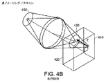
焦点面の上下の、焦点外の領域の寄与は、立体散乱媒体の場合に考慮される必要がある。かなりの性能増強が、共焦点イメージングを用いて実現され得る。3つのイメージングスキームが、図4A〜4Cに示される。 The contribution of out-of-focus regions above and below the focal plane needs to be considered in the case of a three-dimensional scattering medium. Significant performance enhancement can be achieved using confocal imaging. Three imaging schemes are shown in FIGS.
図4Aは、先行技術の全視野イメージング方法における、ピンぼけ光学効果を示す。焦点面の上下の媒体が光を散乱する場合、全視野照射の使用は、以下に説明されるように、重大な欠陥を生じる。図4Aにおいて、均一な光405が、焦点面410に衝突する。焦点面410から距離Zにある、ピンぼけ面420における反射は、焦点の合っていない画像430(検出器平面において、大きいぼやけた円を含む)を提供する。Zに関する強度の強度が、3つの場合、すなわち、全視野イメージング、「飛点」イメージング、およびラインスキャンイメージングについて、分析される。
FIG. 4A shows the defocus optical effect in a prior art full-field imaging method. If the medium above and below the focal plane scatters light, the use of full field illumination results in significant defects, as explained below. In FIG. 4A,
光学理論から、均一な照射I0を有する面積A(媒体の単位体積あたりの反射率関数はΔ(X,Y,Z)であり、そしてイメージングシステムのfナンバーはFである)にわたる単位の拡大について、画像面I(X,Y)における全反射光強度は、式(1)によって与えられる: From optical theory, unit expansion over area A with uniform illumination I 0 (reflectance function per unit volume of medium is Δ (X, Y, Z) and f-number of imaging system is F) The total reflected light intensity at the image plane I (X, Y) is given by equation (1):

MTFは、式(2)において与えられるような、空間周波数(k)の関数として書かれ得る: The MTF can be written as a function of the spatial frequency (k), as given in equation (2):
図4Bは、先行技術の共焦点「飛点」システムにおける、ピンぼけすることの光学効果を示す。強度I(X,Y)についての式は、照射レーザー光を開口と共焦点の点に集束させる結果としての改変を除いて、同じままである。このことは、式(1)における分母に、おなじピンぼけ因子を加える。ピンぼけ光の範囲は、Z−2ではなく、Z−4と共に減少する。面積にわたって積分することによって、得られる距離ゲート関数は、Z−2の次元を有する。全ゲート半値幅は、ちょうど、視野の深さの通常の定義である。Δのこの重み付けは、Z方向に積分可能であり、その結果、周囲の組織からの均一な散乱は、焦点面画像コントラストを破壊しない。先行技術の共焦点飛点方法は、吸収および散乱に起因する消光のみによって制限される、固有の断面化(sectioning)特性を提供する。 FIG. 4B shows the optical effect of defocusing in a prior art confocal “flying point” system. The equation for intensity I (X, Y) remains the same except for the modifications that result from focusing the illuminating laser light to a point confocal with the aperture. This adds the same defocus factor to the denominator in equation (1). The range of defocused light decreases with Z- 4 , not Z- 2 . By integrating over the area, the resulting distance gate function has a dimension of Z- 2 . The full width at half maximum of the gate is just the usual definition of the depth of field. This weighting of Δ can be integrated in the Z direction so that uniform scattering from surrounding tissue does not destroy the focal plane image contrast. Prior art confocal flight point methods provide inherent sectioning properties that are limited only by quenching due to absorption and scattering.
図4Cは、本発明のLSLOのような、ラインスキャンイメージングシステムにおけるピンぼけすることの光学効果を示す。ラインスキャンシステムについて、このシステムは、光学的構成要素450の使用によって、レーザー光435を、線形検出器アレイ440と共焦点のラインに集束させる。この構成において、照射強度は、Z−1として低下する。従って、ピンぼけ強度は、Z−3として低下する。面積にわたって積分することによって、得られる距離ゲート関数は、Z−1依存性を有し、ゲート幅は、視野の深さに比例する。しかし、Δのこの重み付けは、Z軸方向に積分可能ではない。むしろ、これは、弱い対数発散のみを有する。周囲の組織からの均一な散乱は、焦点面の画像コントラストを低下させる。それにもかかわらず、ラインスキャンシステムは、有用な断面化特性を提供する。なぜなら、コントラストは、厚いサンプルにおいてより遅く低下し、そしてより遠隔にある媒体オプティクスに対してはるかに感受性が低いからである。
FIG. 4C illustrates the optical effect of defocusing in a line scan imaging system, such as the LSLO of the present invention. For a line scan system, the system focuses
レーザーイメージングシステムは、一般に、スペックルパターンを示す傾向があり、そしてこのことは、SLOとLSLOとの両方についてそうである。屈折率の変化を有するほぼ平滑な界面を除いて、生物学的系は、サイズおよび分離が数ナノメートル〜数ミクロンで、空間的に分布した部位からの光を散乱させる傾向がある。レーザー光は、空間的に干渉性であるので、このことは、ビームに沿った反射の位相関係が(少なくとも、1つのコヒーレント長内で)保存されることを意味する。このような領域から収集される光の全強度は、多くの寄与の干渉の合計である。振幅の合計の酔歩の性質は、特に、開口またはピクセルのサイズが回折限界の近くである場合に、開口または各ピクセルにおける電力低下の大きな変動を有する、強め合う干渉および弱め合う干渉を生じる。回折限界は、横断方向での「1スペックル」とみなされ得る。この効果は、頻繁に、いくらかのスペックルを平均により除去する傾向がある、より大きい面積の低い共焦点の(より大きい)開口を使用することによって、相殺される。この解決法は、LSLOに大して利用可能ではなく、そしてLSLOイメージングは、大まかに、いわゆる「厳密に共焦点の」SLOイメージングと等価である。効果的な画像解像度は、干渉の場合に、およそ半減する。 Laser imaging systems generally tend to exhibit speckle patterns, and this is the case for both SLO and LSLO. With the exception of nearly smooth interfaces with refractive index changes, biological systems tend to scatter light from spatially distributed sites with sizes and separations of a few nanometers to a few microns. Since laser light is spatially coherent, this means that the phase relationship of reflection along the beam is preserved (at least within one coherent length). The total intensity of light collected from such an area is the sum of many contributing interferences. The nature of the random walk of amplitude results in constructive and destructive interference with large variations in power drop at the aperture or each pixel, especially when the aperture or pixel size is near the diffraction limit. The diffraction limit can be regarded as “one speckle” in the transverse direction. This effect is often counterbalanced by using a larger area, lower confocal (larger) aperture that tends to remove some speckle by average. This solution is not very available for LSLO, and LSLO imaging is roughly equivalent to so-called “strictly confocal” SLO imaging. The effective image resolution is approximately halved in the case of interference.
有意な改善は、スーパールミネッセントダイオード照射を使用することによって、実現される。25nmの帯域幅および約10μmの可干渉距離を有する、現在市販されているデバイスは、低価格で、数ミリワットの電力レベルで利用可能である。組織における視野の深さにわたって、スペックルは、実質的に平均されて除去され、横断方向の解像度の損失なしに、より平滑な、顆粒の少ない画像を生じる。 Significant improvement is achieved by using superluminescent diode illumination. Currently commercially available devices with a 25 nm bandwidth and a coherence distance of about 10 μm are available at low cost and at power levels of a few milliwatts. Over the depth of field in the tissue, speckle is substantially averaged out, resulting in a smoother, less-granular image without loss of transverse resolution.
本発明の原理を使用するLSLOの光収集挙動は、標準的な点スキャンシステムと比較される。計算のために使用されるモデルは、同一の光学的形状および検出器量子効率を仮定する。両方のシステムを、垂直方向に、フレーミング速度でスキャンするようにモデル化される。30Hzのフレーミング速度での500×500の画像について、SLOの水平方向のスキャン速度fHは、15kHzである。「飛点」検出器は、fHの帯域幅×1つの線あたりのピクセルの数NHpixを必要とする。15kHzでの500の水平方向ピクセルを分解するために、帯域幅は、10MHzより大きい。これは、数ミリワットまでの全電力が、検出器開口と共焦点で、網膜に集束されるので、達成され得る。収集される反射電力は、入射電力PI(すなわち、1mW)、網膜の局所反射率R(X,Y)(NIRにおいて10%未満)、および収集立体角Ω(約10−3sr)に依存する。この量は、約1〜約100nWの代表的な範囲になる。シリコン検出器の雑音等価電力(NEP)は、1つの雑音寄与であり、そして別の雑音寄与は、散弾雑音である。認容可能な信号対雑音非のSNRは、必要とされる帯域幅内で容易に達成される。8ビットの画像のダイナミックレンジは、平均範囲を完全に利用するために、255より大きいSNRを必要とする(すなわち、信号強度より低い雑音レベルが、少なくとも有意なビットによって提示される)。 The light collection behavior of LSLO using the principles of the present invention is compared to a standard point scan system. The model used for the calculation assumes the same optical shape and detector quantum efficiency. Both systems are modeled to scan in the vertical direction at a framing rate. For a 500 × 500 image at a framing speed of 30 Hz, the SLO horizontal scan speed f H is 15 kHz. The “flying point” detector requires f H bandwidth × number of pixels per line N Hpix . To resolve 500 horizontal pixels at 15 kHz, the bandwidth is greater than 10 MHz. This can be achieved because the total power up to a few milliwatts is focused on the retina, confocal with the detector aperture. The reflected power collected depends on the incident power P I (ie, 1 mW), the local reflectance R (X, Y) of the retina (less than 10% in NIR), and the collected solid angle Ω (about 10 −3 sr). To do. This amount will be in the typical range of about 1 to about 100 nW. The noise equivalent power (NEP) of a silicon detector is one noise contribution, and another noise contribution is shot noise. Acceptable signal-to-noise SNR is easily achieved within the required bandwidth. The dynamic range of an 8-bit image requires an SNR greater than 255 in order to fully utilize the average range (ie, a noise level lower than the signal strength is presented by at least significant bits).
この場合について、SNRは、以下のように書かれ得る: For this case, the SNR can be written as:
このモデルはまた、先行技術の全画像の場合に拡張され得る。全視野作動における正方形CCDアレイについて、1ピクセルあたりの電力レベルは、別の因子Nlines(≒NHpix)によってなおさらに低下させる。検出器/増幅器の雑音は、最もありそうには、優勢であり、そしてCCDイメージングは、これらの眼の安全性が低い光レベルにおいては、雑音が多くなる。閃光基底イメージングまたはより高い照射電力が使用されなければならず、そして全ての共焦点の利点は、失われる。 This model can also be extended in the case of all prior art images. For square CCD arrays in full field operation, the power level per pixel is still further reduced by another factor N lines ( ≈N Hpix ). Detector / amplifier noise is most likely dominant and CCD imaging is noisy at light levels where these eye safety is low. Flash-based imaging or higher illumination power must be used, and all confocal benefits are lost.
生物学的サンプル(例えば、眼)と無生物の機械的に作製された標的との両方を使用して、LSLOの作動を試験して、このシステムの解像力および回折限界を決定した。 Both biological samples (eg, eyes) and inanimate mechanically created targets were used to test the operation of LSLO to determine the resolution and diffraction limits of this system.
網膜におけるレーザー線ビームの幅w(線拡散関数における最初の0)は、以下によって与えられる:
w/2 n8feye/d 眼について、Volk 66を用いて約38ミクロン、または30Dを用いて約19ミクロン、および
w/2 n8fmodel/d モデル眼について、Volk 66を用いて約42ミクロン、または30Dを用いて約21ミクロン。
The width w of the laser beam in the retina (the first 0 in the line diffusion function) is given by:
For w / 2 n8f eye / d eye, about 38 microns using Volk 66, or about 19 microns using 30D, and for w / 2 n8f model / d model eye, about 42 microns using Volk 66, or About 21 microns using 30D.
1つの実施形態において、解像標的に基づいて最もよく集束したビーム幅は、いくらかより大きいようである。このことは、部分的に、光学トレインと最適化されないいくつかの要素における収差、およびおそらく、光学表面からの前方散乱が原因である。網膜に反映されるピクセルサイズは、これらのビーム幅におよそ一致するように設計される。Volk 66および30Dについて、モデル角膜におけるピクセルの対角線は、それぞれ、40μmおよび20μmである。水平方向および垂直方向のNyquist限界は、ピクセル間隔の2倍、すなわち、これらの2つの倍率について、56μmおよび28μmであり、または1ミリメートルあたり17対の線および35対の線である。 In one embodiment, the best focused beam width based on the resolution target appears to be somewhat larger. This is partly due to aberrations in some elements that are not optimized with the optical train, and possibly forward scattering from the optical surface. The pixel size reflected in the retina is designed to approximately match these beam widths. For Volk 66 and 30D, the pixel diagonals in the model cornea are 40 μm and 20 μm, respectively. The horizontal and vertical Nyquist limits are twice the pixel spacing, ie, 56 μm and 28 μm for these two magnifications, or 17 and 35 pairs of lines per millimeter.
一定の3mmの眼入口瞳孔、すなわち、Volk 66および30Dについてそれぞれ、瞳孔接合部において約7mmおよび14mmを用いると、40mmの対物レンズに起因するCCDアレイにおけるAiry回折は、11.7μmおよび5.8μmである。一次近似のために、正味の二重通過画像光学分解要素は、これらの寄与の根平均二乗の合計、すなわち、58μmおよび29μmである。これは、ピクセルアレイのNyquist限界に密接に一致する。 Using approximately 7 mm and 14 mm at the pupil junction for a constant 3 mm eye entrance pupil, ie, Volk 66 and 30D, respectively, the Airy diffraction in the CCD array due to the 40 mm objective lens is 11.7 μm and 5.8 μm It is. Due to the first order approximation, the net double pass image optical resolution element is the sum of the root mean squares of these contributions, ie 58 μm and 29 μm. This closely matches the Nyquist limit of the pixel array.
図5Aおよび5Bは、標準的な米国空軍(USAF)解像度標的#51を、それぞれ低倍率および高倍率で示す。モデル眼は、平坦な標的の前面において、無色のものからなるので、検眼鏡レンズは、眼に存在する視野の曲率を過剰に補正する。明るい角膜領域は、高いスキャン角において、視野の深さから標的面を移動する視野曲率に起因する。解像度を、最小の分解可能な三重線の群および線の数を読み上げることによって、決定される。モデル眼オプティクスと干渉する、Volk 66レンズのいくらかの焦点の不規則性にもかかわらず、USAF標的三重線が見えることの限界から判断した解像度は、以下である:
低倍率の40°の視野について:群2、線6、1mmあたり7対の線または1対の線あたり143μmに対応する
高倍率の20°の視野について:群3、線6、1mmあたり14.3対の線または1対の線あたり70μmに対応する。
FIGS. 5A and 5B show a standard US Air Force (USAF) resolution target # 51 at low and high magnification, respectively. Since the model eye is made of colorless in front of the flat target, the ophthalmoscope lens overcorrects the curvature of the field of view present in the eye. The bright corneal region is due to the field curvature moving from the depth of field to the target surface at high scan angles. The resolution is determined by reading the minimum group of resolvable triple lines and the number of lines. Despite some focal irregularities of the Volk 66 lens that interfere with model eye optics, the resolution determined from the limit of visibility of the USAF target triplet is:
For low magnification 40 ° field of view: corresponding to
各場合において、およそ5ピクセルが、限界解像度において、線の間に計数され得る。これらの解像度の値は、予測される計算された非干渉値のおよそ2倍である。コントラストは、Nyquist限界の近くで消滅すると予測され、そして干渉照射が見えることの閾値は、常に、この限界のいくらか上(通常、2倍)にある。艶消し標的表面自体のわずかな半透明性は、LSLOオプティクスの無関係なコントラストの見かけの減少、および非常にスペックル化した外観(これは、見かけの解像度に対して有害な影響を有する)を生じた。第一の網膜接合部に直接(Volkレンズなしで)配置された、より密度の濃い標的(例えば、米国の1ドル札の裏面に見られる画像)は、図6Aおよび6Bにおいてのように、改善された外観を有する。観察される別の興味深い効果は、図5Bに明らかに見られる、水平な棒と垂直な棒との間のコントラストの差である。これは、イメージングされた線の左右への、明るいピクセルの接近の効果として理解され得る。2ピクセルまたは3ピクセルのみの幅の垂直な線は、隣の明るい領域からのかなりのバックグラウンド寄与を有し、そのPSFは、2ピクセルにわたって広がる。しかし、水平な暗い線において、この線上の隣接するピクセルは、線の端部を除いて暗く、コントラストのための重要性はほとんどまたは全くない。 In each case, approximately 5 pixels can be counted between the lines at the limiting resolution. These resolution values are approximately twice the predicted calculated non-interference values. Contrast is expected to disappear near the Nyquist limit, and the threshold for visible interference illumination is always somewhere above this limit (usually twice). The slight translucency of the matte target surface itself results in an irrelevant reduction in LSLO optics's irrelevant contrast and a very speckled appearance, which has a detrimental effect on the apparent resolution. It was. A denser target (eg, the image seen on the back of a US dollar bill) placed directly (without the Volk lens) at the first retinal junction is improved as in FIGS. 6A and 6B. Has an external appearance. Another interesting effect observed is the difference in contrast between the horizontal and vertical bars, clearly seen in FIG. 5B. This can be understood as the effect of a bright pixel approach to the left and right of the imaged line. A vertical line that is only 2 or 3 pixels wide has a significant background contribution from the adjacent bright area, and its PSF extends over 2 pixels. However, in a horizontal dark line, adjacent pixels on this line are dark except at the ends of the line and have little or no importance for contrast.
レーザー線の幅w/2 n8f/dは、Volk 66については約40ミクロンであり、または30Dについては約20ミクロンであった。レーザー線の長さを、目的の視野を約40°および20°、水平に覆うように設定した。7mmのCCDアレイに沿って最小の輝度の変動を有するために、FWHMを、固定された円柱形レンズの焦点距離を介してスケールを合わせ、モデル角膜において、7mm以上であった。約1mWの電力が、線の中心の7mmで非常に均一に低下し、これは、最悪の場合(例えば、30Dオプティクスの使用)における電力密度の計算のために有用である:
長さL 約0.7cm。
The laser line width w / 2 n8f / d was about 40 microns for Volk 66 or about 20 microns for 30D. The length of the laser line was set to cover the intended field of view approximately 40 ° and 20 ° horizontally. In order to have minimal brightness variation along a 7 mm CCD array, the FWHM was scaled through the focal length of a fixed cylindrical lens and was greater than 7 mm in the model cornea. About 1 mW of power drops very uniformly at 7 mm in the center of the line, which is useful for power density calculations in the worst case (eg, using 30D optics):
Length L About 0.7cm.
網膜における静止線電力密度1mW/(wL) 約500mW/cm2。このような電力密度での、830nmでの安全な曝露時間は、少なくとも10秒間であり、そして被験体が凝視を避けるために必要とされる時間、またはスキャナの故障の場合に操作者が入ってくる光をブロックするかもしくは光源をオフにするために必要とされる時間と一致する。
Static line power density in
角膜と等価の平面波が、角膜における電力を決定することによって、推定され得、これは、単一の30×30ミクロンのスポット(すなわち、ラインの1つの実際のレーザー要素)上のこの電力密度に対応する。これは、入射電力の単なる1/250乗、すなわち、約4μW未満である。 A plane wave equivalent to the cornea can be estimated by determining the power in the cornea, which is at this power density on a single 30 × 30 micron spot (ie one actual laser element in the line). Correspond. This is just 1 / 250th of the incident power, ie less than about 4 μW.
0.7cmを通して垂直方向にスキャンされて、正方形の画像を形成する場合、網膜における時間平均電力密度は、この電力の1/300乗、さらに低い:レーザーラインスキャン(全視野7mm×7mm)の平均電力密度は、約2mW/cm2である。 When scanned vertically through 0.7 cm to form a square image, the time average power density in the retina is 1 / 300th of this power, even lower: the average of the laser line scan (total field of view 7 mm × 7 mm) The power density is about 2 mW / cm 2 .
LSLOの主要な安全特徴は、垂直方向のスキャナが故障している場合でさえも、レーザーインターロックが必要とされないことである。なぜなら、静止したライン自体は、志願者が眼を逸らせるために必要とされる数秒間にわたって、眼に安全であるからである。固定された円柱形オプティクス(これは、器具を解体せずには取り外され得ない)は、網膜における電力密度が、引用される値より決して大きくなり得ないことを確実にする。 The main safety feature of LSLO is that no laser interlock is required even if the vertical scanner has failed. This is because the stationary line itself is safe to the eye for the number of seconds required for the volunteer to look away. Fixed cylindrical optics, which cannot be removed without dismantling the instrument, ensure that the power density in the retina can never be greater than the quoted value.
本発明のLSLOは、広視野画像の獲得を介して、先行技術のSLOと比較された。ヒト被験体の左右の眼の40°の視野のLSLO画像が、それぞれ図7Aおよび7Bに示される。鮮明な画像が、LSLOを用いて得られ、そして共焦点赤外画像の代表的な特徴が見られた:暗いディスク、よく分解された明るい脈管の管腔、より明るい動脈およびより暗い静脈、いくつかの被験体における窩の反射、毛細管および脈絡膜の脈管、ならびに色素沈着の変化。左眼を示す図7Aは、網膜の瘢痕および以前の漿液性中心性網膜症の残留する特徴を示す。これらの画像および中程度の視野の深さのために必要とされる瞳孔が比較的小さいことに起因して、明瞭な画像が、周囲においてよく得られ得る。比較のために、わずかに高い倍率の、先行技術の標準的なSLO画像が、図8に示される。 The LSLO of the present invention was compared to prior art SLOs through wide field image acquisition. LSLO images of a 40 ° field of view of the left and right eyes of a human subject are shown in FIGS. 7A and 7B, respectively. A clear image was obtained using LSLO, and typical features of the confocal infrared image were seen: dark disc, well resolved bright vascular lumen, brighter arteries and darker veins, Changes in foveal reflexes, capillaries and choroidal vessels, and pigmentation in some subjects. FIG. 7A, showing the left eye, shows the remaining features of retinal scars and previous serous central retinopathy. Due to the relatively small pupils required for these images and moderate depth of field, clear images can be obtained well around. For comparison, a slightly higher magnification prior art standard SLO image is shown in FIG.
本発明のLSLOの能力は、黄斑およびディスクの画像を記録することによって、実証される。ヒト被験体における20°の視野のLSLO画像の選択が、図9Aおよび9Bに示される。これらの画像は、静脈および動脈、網膜神経線維の窩の反射、ならびに他の形態を、区別して示す。 The ability of the LSLO of the present invention is demonstrated by recording macular and disc images. Selection of a LSLO image of a 20 ° field of view in a human subject is shown in FIGS. 9A and 9B. These images differentiate and show veins and arteries, retinal nerve fiber foveal reflections, and other morphologies.
いくつかの実施形態において、LSLOは、立体対を収集する能力を提供する。従来の立体イメージングにおいて、瞳孔の開口は、光学的に分離され、そして左右の視野に対応する2つの画像が捕捉される。2つの画像の間の視差は、深さの情報を含む。視野の深さは、個々の視野の開口数によって決定される。異なる視角を有するLSLOの視野の有限の深さに起因して、これは、深さの情報を集める際に等しく効果的である。しかし、さらに、その共焦点性に起因して、焦点の面の上下からのピンぼけ光が、抑制される。このことは、より深い網膜構造体の、優れた3D可視化を可能にする。 In some embodiments, LSLO provides the ability to collect stereo pairs. In conventional stereo imaging, the pupil opening is optically separated and two images corresponding to the left and right fields of view are captured. The parallax between the two images includes depth information. The depth of field is determined by the numerical aperture of the individual field. Due to the finite depth of the field of view of LSLO with different viewing angles, this is equally effective in collecting depth information. However, due to the confocality, defocused light from above and below the focal plane is suppressed. This allows for excellent 3D visualization of deeper retinal structures.
図10Aおよび10Bは、LSLOを用いて連続して捕捉された、瞳孔の位置が約1〜2mm横方向にシフトした、例示的なディスクの画像の対を示す。この純粋に横方向の瞳孔のシフトは、同じ画像が、3〜6°離れた2つの視角において捕捉されることを可能にし、そして予測された、実況の動き、分離した瞳孔開口の双眼LSLO操作の効果的なシミュレーションである。これらの画像は、図10Aおよび10Bにおいて、横に並べて表示されており、その結果、その紙面から2フィート(60cm)以上離して見る場合に、この画像は、立体視に融合され得る。 FIGS. 10A and 10B show an example pair of images of a disc captured sequentially using LSLO, with the pupil position shifted about 1-2 mm laterally. This purely lateral pupil shift allows the same image to be captured at two viewing angles that are 3-6 ° apart, and predicted motion, binocular LSLO manipulation of separate pupil apertures This is an effective simulation. These images are displayed side by side in FIGS. 10A and 10B so that they can be fused into a stereoscopic view when viewed more than two feet (60 cm) from the page.
図10Aおよび10Bにおいて、ディスクの近くの脈管の形状および配向が、はっきりと見える。左/右の焦点は、連続的な画像捕捉に起因して、わずかに異なる。画像における穏やかな曇りの感覚は、画像に低い解像度(500×512)およびスペックルに起因する。高い解像度の画像、およびおそらくスーパールミネッセントダイオード(SLD)照射は、粒度を大いに減少させるはずである。 In FIGS. 10A and 10B, the shape and orientation of the vessel near the disc is clearly visible. The left / right focus is slightly different due to continuous image capture. The mild haze sensation in the image is due to the low resolution (500 × 512) and speckle in the image. High resolution images, and possibly superluminescent diode (SLD) illumination, should greatly reduce the granularity.
図11は、共焦点の前区イメージングの実証を示す。図11の画像は、検眼鏡の対物レンズを除去し、そして被験体の眼の前区を、接合画像面に配置する場合に、得られた。 FIG. 11 shows a demonstration of confocal anterior imaging. The image of FIG. 11 was obtained when the objective lens of the ophthalmoscope was removed and the anterior segment of the subject's eye was placed on the bonded image plane.
本発明のLSLOの実施形態は、好ましくは、2つの倍率で作動し、そして前区のイメージング、および後区の散瞳なしでのイメージングを可能にするように構成される。1つの実施形態において、これは、回転焦点を有する2つの交換可能な検眼鏡レンズのうちの1つを使用して、達成される。他の実施形態において、検眼鏡レンズは、取り外し可能であり、そして交換可能であり得るか、またはLSLOは、検眼鏡レンズなしで作動し得る。LSLOデバイスは、外部画像獲得、コンピュータまたはCRTの必要なしに、画像獲得のために必要とされる全てのエレクトロニクスおよびオプティクスを組み込む。LSLOデバイスは、オンボードカメラに捕捉される、画像保存および画像ダウンロードを提供する。 Embodiments of the LSLO of the present invention preferably operate at two magnifications and are configured to allow anterior segment imaging and posterior segment mydriatic imaging. In one embodiment, this is achieved using one of two interchangeable ophthalmoscope lenses having a rotating focus. In other embodiments, the ophthalmic lens can be removable and replaceable, or the LSLO can operate without an ophthalmoscopic lens. The LSLO device incorporates all the electronics and optics required for image acquisition without the need for external image acquisition, computer or CRT. The LSLO device provides image storage and image download captured by an on-board camera.
いくつかの実施形態において、2つの実質的に類似の器具を一緒に使用することにより、さらなる機能性が提供され得る。二重のチャネルが一体化され得、これは、多波長での作動およびリアルタイムの双眼イメージングのために構成され得る。着用可能なマイクロディスプレイ技術は、操作者が、このデバイスを、妨害されない視野で操作することを可能にし、同時に、(例えば、上方または下方に)軸から数度ずれてカラー/立体(左右の眼)ディスプレイを見ることを可能にする。このディスプレイは、携帯型デバイスの近くに合わさり、その結果、最小の収容が必要とされ、一方で、患者から立体ディスプレイへの凝視をシフトさせるようである。調節可能な顔面支持システムまたはマスク(これは、操作者が患者に隣接させて適所に装置を穏やかに保持することを可能にする)の使用は、軽量LSLOが任意の配向で患者のために必要とする安定性および接合の全てを提供する。 In some embodiments, additional functionality can be provided by using two substantially similar instruments together. Dual channels can be integrated, which can be configured for multi-wavelength operation and real-time binocular imaging. Wearable microdisplay technology allows the operator to operate the device with an unobstructed field of view, while at the same time color / solid (left and right eyes) offset several degrees from the axis (eg, up or down). ) Allows you to see the display. This display seems to fit close to the portable device, so that minimal containment is required while shifting the gaze from the patient to the stereoscopic display. The use of an adjustable facial support system or mask (which allows the operator to gently hold the device in place adjacent to the patient) requires a lightweight LSLO for the patient in any orientation Provides all of the stability and bonding.
(等価物)
本発明は、特定の好ましい実施形態を参照して、特に図示および記載されたが、形式および細部における種々の変化が、添付の特許請求の範囲によって規定されるような、本発明の精神および範囲から逸脱することなく、本発明においてなされ得ることが、当業者によって理解されるべきである。
(Equivalent)
Although the invention has been particularly illustrated and described with reference to certain preferred embodiments, the spirit and scope of the invention, as various changes in form and detail are defined by the appended claims. It should be understood by those skilled in the art that it can be made in the present invention without departing from the invention.
Claims (19)
実質的に点である光源を提供する、光源;
光学装置であって、以下:
該光源から光を受光し、そして入ってくる光のラインを提供する光学的構成要素;
スキャンミラーであって、(i)眼の一部を、該入ってくる光のラインで、該ラインに対して垂直な方向でスキャンし、(ii)該眼の照射された部分からの反射光を共焦点で受光し、そして(iii)集束ラインの形態で、光の出力を提供するように構成されたスキャンミラー;
スキャンレンズならびに第1および第2の検眼鏡レンズであって、これらを介して、該スキャンミラーは、該入ってくる光のラインで該眼の一部をスキャンするように構成される、スキャンレンズならびに第1および第2の検眼鏡レンズ;
該入ってくる光および該反射光のうちの選択された1つを再指向する、回転ミラー、
を備える、光学装置;ならびに
一次元検出器であって、該出力光を検出し、そして該出力光のラインに沿った複数の位置の各々において、該出力光に応答性の電気信号を提供する、一次元検出器、
を備える、ラインスキャンレーザー検眼鏡。A line scan laser ophthalmoscope, with the following:
Providing a light source that is substantially a point;
An optical science apparatus, the following:
An optical component that receives light from the light source and provides a line of incoming light;
(I ) scanning a part of the eye with the incoming light line in a direction perpendicular to the line; (ii) reflected light from the irradiated part of the eye A scanning mirror configured to receive the light at a confocal and provide a light output in the form of (ii i ) a focusing line ;
A scan lens and first and second ophthalmoscope lenses, through which the scan mirror is configured to scan a portion of the eye with the incoming line of light And first and second ophthalmoscopic lenses;
A rotating mirror that redirects a selected one of the incoming light and the reflected light;
An optical device; and a one-dimensional detector for detecting the output light and providing an electrical signal responsive to the output light at each of a plurality of positions along the line of output light , One-dimensional detector,
A line scan laser ophthalmoscope.
所望でない光が該光学装置を通って進むことを防止する、瞳孔絞り;および
該反射光の再指向されたラインを、前記一次元検出器に集束させる、対物レンズ、
を備える、請求項1に記載のラインスキャンレーザー検眼鏡。The optical device further comprises :
Light not Nozomu Tokoro is prevented from traveling through the optical device, pupil aperture; a and reflected light re-directed the line of focusing on the one-dimensional detector, an objective lens,
The line scan laser ophthalmoscope according to claim 1, comprising:
前記集束ラインの形態の光を第一の光のビームと第二の光のビームとに分離するための光学要素であって、前記一次元検出器が、該第一の光のビームを受光する、光学要素;および
該第二の光のビームを受光するための第二の検出器、
を備える、ラインスキャンレーザー検眼鏡。The line scan laser ophthalmoscope according to claim 1, further comprising:
An optical chemical element for separating the light in the form of the focused line and the beam of the first light beam and a second light, the one-dimensional detector, receiving a beam of said first light to the optical science elements; and for receiving the beam of the second light second detector,
A line scan laser ophthalmoscope.
信号分析モジュールであって、前記一次元検出器からの電気信号を復号し、そして前記眼の照射される部分からの反射光に応答性のデータのアレイを作製する、信号分析モジュール、
を備える、請求項1に記載のラインスキャンレーザー検眼鏡。In addition:
A signal analysis module for decoding an electrical signal from the one-dimensional detector and creating an array of data responsive to reflected light from the illuminated part of the eye;
The line scan laser ophthalmoscope according to claim 1 , comprising:
ディスプレイモジュールであって、前記信号分析モジュールによって作製されたデータのアレイを表す情報を表示する、ディスプレイモジュール、
を備える、請求項14に記載のラインスキャンレーザー検眼鏡。In addition:
A display module for displaying information representative of an array of data produced by the signal analysis module;
The line scan laser ophthalmoscope according to claim 14 .
Applications Claiming Priority (2)
| Application Number | Priority Date | Filing Date | Title |
|---|---|---|---|
| US10/171,883 US6758564B2 (en) | 2002-06-14 | 2002-06-14 | Line-scan laser ophthalmoscope |
| PCT/US2003/018839 WO2003105679A1 (en) | 2002-06-14 | 2003-06-13 | Line-scan laser ophthalmoscope |
Publications (3)
| Publication Number | Publication Date |
|---|---|
| JP2005529669A JP2005529669A (en) | 2005-10-06 |
| JP2005529669A5 JP2005529669A5 (en) | 2006-10-12 |
| JP4621496B2 true JP4621496B2 (en) | 2011-01-26 |
Family
ID=29732880
Family Applications (1)
| Application Number | Title | Priority Date | Filing Date |
|---|---|---|---|
| JP2004512595A Expired - Fee Related JP4621496B2 (en) | 2002-06-14 | 2003-06-13 | Line scan ophthalmoscope |
Country Status (8)
| Country | Link |
|---|---|
| US (2) | US6758564B2 (en) |
| EP (1) | EP1513441B1 (en) |
| JP (1) | JP4621496B2 (en) |
| AT (1) | ATE493928T1 (en) |
| AU (1) | AU2003276035A1 (en) |
| CA (1) | CA2489241C (en) |
| DE (1) | DE60335625D1 (en) |
| WO (1) | WO2003105679A1 (en) |
Families Citing this family (115)
| Publication number | Priority date | Publication date | Assignee | Title |
|---|---|---|---|---|
| JP4018425B2 (en) * | 2002-03-29 | 2007-12-05 | 松下電器産業株式会社 | Eye imaging device |
| AU2003299201A1 (en) * | 2002-10-03 | 2004-04-23 | Light Sciences Corporation | Excitation of photoreactive compounds in eye tissue |
| DE10336475B9 (en) | 2003-08-08 | 2006-09-07 | Carl Zeiss | microscopy system |
| JP4492845B2 (en) * | 2003-10-14 | 2010-06-30 | 株式会社ニデック | Laser treatment device |
| US20050097046A1 (en) * | 2003-10-30 | 2005-05-05 | Singfield Joy S. | Wireless electronic check deposit scanning and cashing machine with web-based online account cash management computer application system |
| US7359563B1 (en) * | 2004-04-05 | 2008-04-15 | Louisiana Tech University Research Foundation | Method to stabilize a moving image |
| US7365856B2 (en) | 2005-01-21 | 2008-04-29 | Carl Zeiss Meditec, Inc. | Method of motion correction in optical coherence tomography imaging |
| US7805009B2 (en) * | 2005-04-06 | 2010-09-28 | Carl Zeiss Meditec, Inc. | Method and apparatus for measuring motion of a subject using a series of partial images from an imaging system |
| US20080284848A1 (en) * | 2005-08-26 | 2008-11-20 | Peter Martin | Security surveillance planning tool kit |
| US7758189B2 (en) * | 2006-04-24 | 2010-07-20 | Physical Sciences, Inc. | Stabilized retinal imaging with adaptive optics |
| WO2007130411A2 (en) * | 2006-05-01 | 2007-11-15 | Physical Sciences, Inc. | Hybrid spectral domain optical coherence tomography line scanning laser ophthalmoscope |
| DE502006005346D1 (en) | 2006-07-07 | 2009-12-24 | Od Os Gmbh | ophthalmoscope |
| US7873200B1 (en) | 2006-10-31 | 2011-01-18 | United Services Automobile Association (Usaa) | Systems and methods for remote deposit of checks |
| US8708227B1 (en) | 2006-10-31 | 2014-04-29 | United Services Automobile Association (Usaa) | Systems and methods for remote deposit of checks |
| JP4915737B2 (en) * | 2007-03-13 | 2012-04-11 | 興和株式会社 | Image analysis system and image analysis program |
| US10380559B1 (en) | 2007-03-15 | 2019-08-13 | United Services Automobile Association (Usaa) | Systems and methods for check representment prevention |
| KR100965723B1 (en) | 2007-03-21 | 2010-06-24 | 삼성전자주식회사 | Method for mapping resource of physical downlink control channel of wireless communication system and apparatus for transmitting/receiving physical downlink control channel mapped thereby |
| WO2009004497A2 (en) * | 2007-07-04 | 2009-01-08 | I-Optics Bv | Confocal color ophthalmoscope |
| US9058512B1 (en) | 2007-09-28 | 2015-06-16 | United Services Automobile Association (Usaa) | Systems and methods for digital signature detection |
| US9159101B1 (en) | 2007-10-23 | 2015-10-13 | United Services Automobile Association (Usaa) | Image processing |
| US9892454B1 (en) | 2007-10-23 | 2018-02-13 | United Services Automobile Association (Usaa) | Systems and methods for obtaining an image of a check to be deposited |
| US7792249B2 (en) | 2007-12-23 | 2010-09-07 | Oraya Therapeutics, Inc. | Methods and devices for detecting, controlling, and predicting radiation delivery |
| DE102008000225B3 (en) * | 2008-02-01 | 2009-03-26 | Linos Photonics Gmbh & Co. Kg | fundus |
| US10380562B1 (en) | 2008-02-07 | 2019-08-13 | United Services Automobile Association (Usaa) | Systems and methods for mobile deposit of negotiable instruments |
| EP2306889A4 (en) * | 2008-07-10 | 2012-11-28 | Univ Indiana Res & Tech Corp | Ophthalmic apparatuses, systems and methods |
| US10504185B1 (en) | 2008-09-08 | 2019-12-10 | United Services Automobile Association (Usaa) | Systems and methods for live video financial deposit |
| US20100245765A1 (en) * | 2008-10-28 | 2010-09-30 | Dyer Holdings, Llc | Video infrared ophthalmoscope |
| US8433117B2 (en) * | 2008-11-21 | 2013-04-30 | The United States Of America As Represented By The Secretary Of The Army | Computer controlled system for laser energy delivery to the retina |
| CA2749622A1 (en) * | 2009-01-15 | 2010-07-22 | Physical Sciences, Inc. | Adaptive optics line scanning ophthalmoscope |
| JP2010175448A (en) | 2009-01-30 | 2010-08-12 | Kowa Co | Optical imaging device |
| US8452689B1 (en) | 2009-02-18 | 2013-05-28 | United Services Automobile Association (Usaa) | Systems and methods of check detection |
| US10956728B1 (en) | 2009-03-04 | 2021-03-23 | United Services Automobile Association (Usaa) | Systems and methods of check processing with background removal |
| WO2010113193A1 (en) * | 2009-04-01 | 2010-10-07 | Centervue S.P.A. | Instrument for eye examination |
| US8094355B2 (en) * | 2009-04-29 | 2012-01-10 | Corning Incorporated | Laser projection system with a spinning polygon for speckle mitigation |
| US9779392B1 (en) | 2009-08-19 | 2017-10-03 | United Services Automobile Association (Usaa) | Apparatuses, methods and systems for a publishing and subscribing platform of depositing negotiable instruments |
| US8977571B1 (en) | 2009-08-21 | 2015-03-10 | United Services Automobile Association (Usaa) | Systems and methods for image monitoring of check during mobile deposit |
| US8699779B1 (en) | 2009-08-28 | 2014-04-15 | United Services Automobile Association (Usaa) | Systems and methods for alignment of check during mobile deposit |
| DE102009041996A1 (en) | 2009-09-18 | 2011-03-24 | Carl Zeiss Meditec Ag | Ophthalmic biometry or imaging system and method for acquiring and evaluating measurement data |
| EP2301425B1 (en) | 2009-09-29 | 2019-11-20 | OD-OS GmbH | Ophthalmoscope for observing an eye |
| EP2301424B1 (en) | 2009-09-29 | 2015-07-08 | OD-OS GmbH | Ophthalmoscope with a laser device |
| WO2011050164A1 (en) | 2009-10-21 | 2011-04-28 | Avedro, Inc. | Eye therapy |
| WO2011091253A2 (en) | 2010-01-21 | 2011-07-28 | Physical Sciences, Inc. | Multi-functional adaptive optics retinal imaging |
| JP6377906B2 (en) | 2010-03-19 | 2018-08-22 | アヴェドロ・インコーポレーテッドAvedro,Inc. | System for applying and monitoring eye treatment |
| US9129340B1 (en) | 2010-06-08 | 2015-09-08 | United Services Automobile Association (Usaa) | Apparatuses, methods and systems for remote deposit capture with enhanced image detection |
| NL2005253C2 (en) * | 2010-08-23 | 2012-02-27 | Optics B V I | Confocal line-scan ophthalmoscope. |
| WO2012071387A2 (en) | 2010-11-24 | 2012-05-31 | University Of South Florida | Adaptive optics ophthalmic imager without wavefront sensor or wavefront corrector |
| JP5635898B2 (en) | 2010-12-17 | 2014-12-03 | キヤノン株式会社 | Fundus imaging apparatus and control method thereof |
| CN102008288B (en) * | 2010-12-17 | 2012-02-01 | 中国科学院光电技术研究所 | System and method for line scan confocal ophthalmoscope |
| CN102068236B (en) * | 2010-12-17 | 2012-05-23 | 中国科学院光电技术研究所 | Line-scanning confocal ophthalmoscope system based on laser diffraction and method |
| US9033510B2 (en) | 2011-03-30 | 2015-05-19 | Carl Zeiss Meditec, Inc. | Systems and methods for efficiently obtaining measurements of the human eye using tracking |
| JP5981722B2 (en) | 2011-04-27 | 2016-08-31 | キヤノン株式会社 | Ophthalmic equipment |
| WO2012162529A1 (en) | 2011-05-24 | 2012-11-29 | Avedro, Inc. | Systems and methods for reshaping an eye feature |
| JP6122845B2 (en) * | 2011-06-02 | 2017-04-26 | アヴェドロ・インコーポレーテッドAvedro,Inc. | System and method for monitoring the delivery of time-based photoactive agents or the presence of photoactive markers |
| WO2013004801A1 (en) | 2011-07-07 | 2013-01-10 | Carl Zeiss Meditec Ag | Improved data acquisition methods for reduced motion artifacts and applications in oct angiography |
| JP6057567B2 (en) | 2011-07-14 | 2017-01-11 | キヤノン株式会社 | Imaging control apparatus, ophthalmic imaging apparatus, imaging control method, and program |
| DE102011053880B4 (en) | 2011-09-23 | 2023-11-09 | Carl Zeiss Ag | Device and method for imaging the fundus of the eye |
| US9566190B2 (en) * | 2011-11-25 | 2017-02-14 | Sie Ag, Surgical Instrument Engineering | Device for processing eye tissue by means of a pulsed laser beam |
| US10380565B1 (en) | 2012-01-05 | 2019-08-13 | United Services Automobile Association (Usaa) | System and method for storefront bank deposits |
| US9101294B2 (en) | 2012-01-19 | 2015-08-11 | Carl Zeiss Meditec, Inc. | Systems and methods for enhanced accuracy in OCT imaging of the cornea |
| US20130229620A1 (en) * | 2012-03-05 | 2013-09-05 | Daniel X. Hammer | Enhanced Sensitivity Line Field Detection |
| US9808154B2 (en) * | 2012-07-13 | 2017-11-07 | Retina Biometrix, Llc | Biometric identification via retina scanning with liveness detection |
| US20140079296A1 (en) * | 2012-07-13 | 2014-03-20 | Retina Biometrix, Llc | Biometric identification via retina scanning |
| EP4074294A1 (en) | 2012-07-16 | 2022-10-19 | Avedro, Inc. | Systems and methods for corneal cross-linking with pulsed light |
| US10552810B1 (en) | 2012-12-19 | 2020-02-04 | United Services Automobile Association (Usaa) | System and method for remote deposit of financial instruments |
| US8842273B2 (en) | 2013-02-14 | 2014-09-23 | United Sciences, Llc | Optical measurement of drilled holes |
| CN110338751A (en) | 2013-03-15 | 2019-10-18 | 瓦索普蒂克医疗公司 | Eye examination and disease control using a variety of illumination forms |
| US9456746B2 (en) | 2013-03-15 | 2016-10-04 | Carl Zeiss Meditec, Inc. | Systems and methods for broad line fundus imaging |
| WO2014152707A1 (en) | 2013-03-15 | 2014-09-25 | Blanco Austin | System and method for rejecting afocal light collected from an in vivo human retina |
| US20140347631A1 (en) * | 2013-05-23 | 2014-11-27 | Canon Kabushiki Kaisha | Ophthalmologic imaging apparatus and control method therefor |
| US9498114B2 (en) | 2013-06-18 | 2016-11-22 | Avedro, Inc. | Systems and methods for determining biomechanical properties of the eye for applying treatment |
| WO2014205145A1 (en) | 2013-06-18 | 2014-12-24 | Avedro, Inc. | Systems and methods for determining biomechanical properties of the eye for applying treatment |
| US9188775B2 (en) * | 2013-08-28 | 2015-11-17 | United Sciences, Llc | Optical scanning and measurement |
| US11138578B1 (en) | 2013-09-09 | 2021-10-05 | United Services Automobile Association (Usaa) | Systems and methods for remote deposit of currency |
| WO2015044366A1 (en) * | 2013-09-30 | 2015-04-02 | Carl Zeiss Meditec Ag | High temporal resolution doppler oct imaging of retinal blood flow |
| US9286514B1 (en) | 2013-10-17 | 2016-03-15 | United Services Automobile Association (Usaa) | Character count determination for a digital image |
| US9949637B1 (en) | 2013-11-25 | 2018-04-24 | Verily Life Sciences Llc | Fluorescent imaging on a head-mountable device |
| US9211064B2 (en) | 2014-02-11 | 2015-12-15 | Welch Allyn, Inc. | Fundus imaging system |
| US9237847B2 (en) | 2014-02-11 | 2016-01-19 | Welch Allyn, Inc. | Ophthalmoscope device |
| US20150250383A1 (en) * | 2014-03-05 | 2015-09-10 | Annidis Corporation | Real time visualization of surgical operations on the eye |
| GB2528102B (en) | 2014-07-10 | 2020-04-29 | Optos Plc | Ophthalmoscopes |
| JP6644799B2 (en) | 2014-10-27 | 2020-02-12 | アヴェドロ・インコーポレーテッドAvedro,Inc. | System and method for ocular crosslinking treatment |
| WO2016077747A1 (en) | 2014-11-13 | 2016-05-19 | Avedro, Inc. | Multipass virtually imaged phased array etalon |
| US10105049B2 (en) | 2015-01-16 | 2018-10-23 | Massachusetts Institute Of Technology | Methods and apparatus for anterior segment ocular imaging |
| US11045088B2 (en) | 2015-02-27 | 2021-06-29 | Welch Allyn, Inc. | Through focus retinal image capturing |
| US10799115B2 (en) | 2015-02-27 | 2020-10-13 | Welch Allyn, Inc. | Through focus retinal image capturing |
| EP3285704B1 (en) | 2015-04-24 | 2020-11-18 | Avedro Inc. | Systems for photoactivating a photosensitizer applied to an eye |
| WO2016191342A1 (en) | 2015-05-22 | 2016-12-01 | Avedro, Inc. | Systems and methods for monitoring cross-linking activity for corneal treatments |
| US10402790B1 (en) | 2015-05-28 | 2019-09-03 | United Services Automobile Association (Usaa) | Composing a focused document image from multiple image captures or portions of multiple image captures |
| CN108025011A (en) | 2015-07-21 | 2018-05-11 | 艾维德洛公司 | With the system and method for photosensitizing agents eyes |
| US10136804B2 (en) | 2015-07-24 | 2018-11-27 | Welch Allyn, Inc. | Automatic fundus image capture system |
| WO2017062189A1 (en) * | 2015-08-27 | 2017-04-13 | Retina Biometrix, Llc | Biometric identification via retina scanning with liveness detection |
| JP6651747B2 (en) * | 2015-09-02 | 2020-02-19 | 株式会社ニデック | Scanning laser ophthalmoscope |
| US10506165B2 (en) | 2015-10-29 | 2019-12-10 | Welch Allyn, Inc. | Concussion screening system |
| US10772495B2 (en) | 2015-11-02 | 2020-09-15 | Welch Allyn, Inc. | Retinal image capturing |
| CN105351783A (en) * | 2015-12-04 | 2016-02-24 | 珠海惠尔益电子有限公司 | Plug-in type bulb connecting structure |
| WO2017120217A1 (en) | 2016-01-07 | 2017-07-13 | Welch Allyn, Inc. | Infrared fundus imaging system |
| CN108601522A (en) * | 2016-02-11 | 2018-09-28 | 爱德华多·斯威特莉莎 | Wide-angle stereofunduscope inspection |
| CN107126189B (en) * | 2016-05-31 | 2019-11-22 | 瑞尔明康(杭州)医疗科技有限公司 | Optical module and retina image-forming equipment for retina image-forming |
| US10602926B2 (en) | 2016-09-29 | 2020-03-31 | Welch Allyn, Inc. | Through focus retinal image capturing |
| US10285589B2 (en) | 2016-09-30 | 2019-05-14 | Welch Allyn, Inc. | Fundus image capture system |
| US10631726B2 (en) | 2017-01-11 | 2020-04-28 | Avedro, Inc. | Systems and methods for determining cross-linking distribution in a cornea and/or structural characteristics of a cornea |
| EP3427705B1 (en) * | 2017-07-13 | 2020-04-01 | Ziemer Ophthalmic Systems AG | Device for treating eye tissue using a pulsed laser beam |
| EP3654826A4 (en) * | 2017-07-17 | 2021-03-24 | Welch Allyn, Inc. | Through focus retinal image capturing |
| JP6958367B2 (en) * | 2018-01-10 | 2021-11-02 | 株式会社ニデック | Fundus photography device |
| WO2019138916A1 (en) * | 2018-01-10 | 2019-07-18 | 株式会社ニデック | Fundus imaging device |
| US11766356B2 (en) | 2018-03-08 | 2023-09-26 | Avedro, Inc. | Micro-devices for treatment of an eye |
| US11030752B1 (en) | 2018-04-27 | 2021-06-08 | United Services Automobile Association (Usaa) | System, computing device, and method for document detection |
| CN108524097B (en) * | 2018-05-14 | 2024-02-02 | 苏州君信视达医疗科技有限公司 | Laser therapy imaging device |
| US11096574B2 (en) | 2018-05-24 | 2021-08-24 | Welch Allyn, Inc. | Retinal image capturing |
| JP2022507811A (en) | 2018-11-21 | 2022-01-18 | ユニバーシティ オブ ワシントン | Systems and methods for retinal template matching in remote ophthalmology |
| CN114206200A (en) | 2019-08-01 | 2022-03-18 | 卡尔蔡司医疗技术公司 | Ophthalmic imaging with K-mirror scanning, efficient interferometry, and pupil alignment by spatial frequency analysis |
| JP2022544110A (en) | 2019-08-06 | 2022-10-17 | アヴェドロ・インコーポレーテッド | Photoactivated system and method for corneal cross-linking treatment |
| WO2021049558A1 (en) | 2019-09-11 | 2021-03-18 | Topcon Corporation | Method and apparatus for stereoscopic color eye imaging |
| JP2021142173A (en) * | 2020-03-13 | 2021-09-24 | 株式会社トプコン | Ophthalmologic device, control method thereof, and program |
| US11900755B1 (en) | 2020-11-30 | 2024-02-13 | United Services Automobile Association (Usaa) | System, computing device, and method for document detection and deposit processing |
Family Cites Families (23)
| Publication number | Priority date | Publication date | Assignee | Title |
|---|---|---|---|---|
| US4569354A (en) | 1982-03-22 | 1986-02-11 | Boston University | Method and apparatus for measuring natural retinal fluorescence |
| FR2555039B1 (en) | 1983-11-21 | 1986-04-04 | Centre Nat Rech Scient | SCANNING CATADIOPTRIC OPHTHALMOSCOPE |
| US4768873A (en) | 1985-09-17 | 1988-09-06 | Eye Research Institute Of Retina Foundation | Double scanning optical apparatus and method |
| US4764005A (en) | 1985-09-17 | 1988-08-16 | Eye Research Institute Of Retina Foundation | Double scanning optical apparatus |
| US4768874A (en) * | 1987-09-10 | 1988-09-06 | Eye Research Institute Of Retina Foundation | Scanning optical apparatus and method |
| US4883061A (en) | 1988-02-29 | 1989-11-28 | The Board Of Trustees Of The University Of Illinois | Method and apparatus for measuring the thickness of eye components |
| US5309187A (en) | 1992-03-18 | 1994-05-03 | Ocular Instruments, Inc. | High magnification ophthalmic lens |
| US5437274A (en) | 1993-02-25 | 1995-08-01 | Gholam A. Peyman | Method of visualizing submicron-size vesicles and particles in blood circulation |
| JP3386839B2 (en) * | 1993-02-25 | 2003-03-17 | 興和株式会社 | Ophthalmic examination device |
| JP3369623B2 (en) * | 1993-03-16 | 2003-01-20 | 興和株式会社 | Laser scanning ophthalmic imaging device |
| US5526189A (en) | 1994-10-26 | 1996-06-11 | Heacock; Gregory L. | Lens for observation of the interior of the eye |
| IL117241A (en) | 1996-02-23 | 2000-09-28 | Talia Technology Ltd | Three dimensional imaging apparatus and a method for use thereof |
| US5784148A (en) | 1996-04-09 | 1998-07-21 | Heacock; Gregory Lee | Wide field of view scanning laser ophthalmoscope |
| US5673097A (en) | 1996-04-15 | 1997-09-30 | Odyssey Optical Systems Llc | Portable scanning laser ophthalmoscope |
| GB9618691D0 (en) | 1996-09-06 | 1996-10-16 | Univ Aberdeen | Scanning laser ophthalmoscope |
| US6027216A (en) | 1997-10-21 | 2000-02-22 | The Johns University School Of Medicine | Eye fixation monitor and tracker |
| US5976502A (en) | 1997-10-21 | 1999-11-02 | Gholam A. Peyman | Method of visualizing particles and blood cells containing a fluorescent lipophilic dye in the retina and choroid of the eye |
| AUPP062197A0 (en) | 1997-11-28 | 1998-01-08 | Lions Eye Institute Of Western Australia Incorporated, The | Stereo scanning laser ophthalmoscope |
| JPH11197109A (en) * | 1998-01-19 | 1999-07-27 | Kowa Co | Scanning type laser ophthalmoscope |
| US5997141A (en) * | 1998-03-06 | 1999-12-07 | Odyssey Optical Systems, Llc | System for treating the fundus of an eye |
| JP2000060893A (en) * | 1998-08-20 | 2000-02-29 | Kowa Co | Ophthalmological treatment device |
| US6186628B1 (en) | 1999-05-23 | 2001-02-13 | Jozek F. Van de Velde | Scanning laser ophthalmoscope for selective therapeutic laser |
| JP2001057964A (en) * | 1999-08-23 | 2001-03-06 | Canon Inc | Projected imaging device |
-
2002
- 2002-06-14 US US10/171,883 patent/US6758564B2/en not_active Expired - Lifetime
-
2003
- 2003-06-13 AU AU2003276035A patent/AU2003276035A1/en not_active Abandoned
- 2003-06-13 DE DE60335625T patent/DE60335625D1/en not_active Expired - Lifetime
- 2003-06-13 CA CA2489241A patent/CA2489241C/en not_active Expired - Lifetime
- 2003-06-13 AT AT03741989T patent/ATE493928T1/en not_active IP Right Cessation
- 2003-06-13 JP JP2004512595A patent/JP4621496B2/en not_active Expired - Fee Related
- 2003-06-13 WO PCT/US2003/018839 patent/WO2003105679A1/en active Application Filing
- 2003-06-13 EP EP03741989A patent/EP1513441B1/en not_active Expired - Lifetime
-
2004
- 2004-06-09 US US10/864,081 patent/US7284859B2/en not_active Expired - Lifetime
Also Published As
| Publication number | Publication date |
|---|---|
| US6758564B2 (en) | 2004-07-06 |
| CA2489241C (en) | 2012-02-21 |
| US20030231285A1 (en) | 2003-12-18 |
| US20050012899A1 (en) | 2005-01-20 |
| AU2003276035A1 (en) | 2003-12-31 |
| JP2005529669A (en) | 2005-10-06 |
| CA2489241A1 (en) | 2003-12-24 |
| EP1513441B1 (en) | 2011-01-05 |
| WO2003105679A1 (en) | 2003-12-24 |
| US7284859B2 (en) | 2007-10-23 |
| ATE493928T1 (en) | 2011-01-15 |
| EP1513441A1 (en) | 2005-03-16 |
| DE60335625D1 (en) | 2011-02-17 |
Similar Documents
| Publication | Publication Date | Title |
|---|---|---|
| JP4621496B2 (en) | Line scan ophthalmoscope | |
| US11911107B2 (en) | System, method and apparatus for retinal absorption phase and dark field imaging with oblique illumination | |
| US7404640B2 (en) | Monitoring blood flow in the retina using a line-scanning laser ophthalmoscope | |
| JP5735211B2 (en) | Laser scanning digital camera with simple optical system and multiple scattered light imaging function | |
| US8488895B2 (en) | Laser scanning digital camera with pupil periphery illumination and potential for multiply scattered light imaging | |
| Hammer et al. | Line-scanning laser ophthalmoscope | |
| US6350031B1 (en) | Electro-optic binocular indirect ophthalmoscope | |
| JP5451326B2 (en) | Retinographic digital processing device | |
| AU2002251229B2 (en) | Retinal function camera | |
| JP2009538697A5 (en) | ||
| JP2020048695A (en) | Ophthalmologic information processing apparatus, ophthalmologic apparatus, and ophthalmologic information processing method | |
| CA2586139A1 (en) | Optical apparatus and method for comprehensive eye diagnosis | |
| JP2011515189A (en) | Eye imaging | |
| CN115334953A (en) | Multi-modal retinal imaging platform | |
| WO2021183637A1 (en) | Illumination of an eye fundus using non-scanning coherent light | |
| JP7412170B2 (en) | Ophthalmological equipment, its evaluation method, program, and recording medium | |
| Mayne | Dynamic Aperture Imaging with an Adaptive Optics Scanning Laser Ophthalmoscope as an Approach to Studying Light Scatter in the Retina | |
| Hammer et al. | Hand-held digital line-scanning laser ophthalmoscope (LSLO) | |
| Roorda et al. | New directions in imaging the retina | |
| CN114947733A (en) | Eye tissue imaging device and equipment | |
| Reiss | New Advances in Imaging for Vision Research |
Legal Events
| Date | Code | Title | Description |
|---|---|---|---|
| A621 | Written request for application examination |
Free format text: JAPANESE INTERMEDIATE CODE: A621 Effective date: 20060607 |
|
| A521 | Request for written amendment filed |
Free format text: JAPANESE INTERMEDIATE CODE: A523 Effective date: 20060822 |
|
| A131 | Notification of reasons for refusal |
Free format text: JAPANESE INTERMEDIATE CODE: A131 Effective date: 20090127 |
|
| A601 | Written request for extension of time |
Free format text: JAPANESE INTERMEDIATE CODE: A601 Effective date: 20090424 |
|
| A602 | Written permission of extension of time |
Free format text: JAPANESE INTERMEDIATE CODE: A602 Effective date: 20090507 |
|
| A601 | Written request for extension of time |
Free format text: JAPANESE INTERMEDIATE CODE: A601 Effective date: 20090526 |
|
| A602 | Written permission of extension of time |
Free format text: JAPANESE INTERMEDIATE CODE: A602 Effective date: 20090602 |
|
| A601 | Written request for extension of time |
Free format text: JAPANESE INTERMEDIATE CODE: A601 Effective date: 20090623 |
|
| A602 | Written permission of extension of time |
Free format text: JAPANESE INTERMEDIATE CODE: A602 Effective date: 20090630 |
|
| A521 | Request for written amendment filed |
Free format text: JAPANESE INTERMEDIATE CODE: A523 Effective date: 20090723 |
|
| A131 | Notification of reasons for refusal |
Free format text: JAPANESE INTERMEDIATE CODE: A131 Effective date: 20090827 |
|
| A521 | Request for written amendment filed |
Free format text: JAPANESE INTERMEDIATE CODE: A523 Effective date: 20091015 |
|
| A131 | Notification of reasons for refusal |
Free format text: JAPANESE INTERMEDIATE CODE: A131 Effective date: 20100204 |
|
| A601 | Written request for extension of time |
Free format text: JAPANESE INTERMEDIATE CODE: A601 Effective date: 20100428 |
|
| A602 | Written permission of extension of time |
Free format text: JAPANESE INTERMEDIATE CODE: A602 Effective date: 20100511 |
|
| A601 | Written request for extension of time |
Free format text: JAPANESE INTERMEDIATE CODE: A601 Effective date: 20100603 |
|
| A602 | Written permission of extension of time |
Free format text: JAPANESE INTERMEDIATE CODE: A602 Effective date: 20100610 |
|
| A601 | Written request for extension of time |
Free format text: JAPANESE INTERMEDIATE CODE: A601 Effective date: 20100630 |
|
| A602 | Written permission of extension of time |
Free format text: JAPANESE INTERMEDIATE CODE: A602 Effective date: 20100707 |
|
| A521 | Request for written amendment filed |
Free format text: JAPANESE INTERMEDIATE CODE: A523 Effective date: 20100804 |
|
| TRDD | Decision of grant or rejection written | ||
| A01 | Written decision to grant a patent or to grant a registration (utility model) |
Free format text: JAPANESE INTERMEDIATE CODE: A01 Effective date: 20101025 |
|
| A01 | Written decision to grant a patent or to grant a registration (utility model) |
Free format text: JAPANESE INTERMEDIATE CODE: A01 |
|
| A61 | First payment of annual fees (during grant procedure) |
Free format text: JAPANESE INTERMEDIATE CODE: A61 Effective date: 20101101 |
|
| FPAY | Renewal fee payment (event date is renewal date of database) |
Free format text: PAYMENT UNTIL: 20131105 Year of fee payment: 3 |
|
| R150 | Certificate of patent or registration of utility model |
Free format text: JAPANESE INTERMEDIATE CODE: R150 |
|
| R250 | Receipt of annual fees |
Free format text: JAPANESE INTERMEDIATE CODE: R250 |
|
| R250 | Receipt of annual fees |
Free format text: JAPANESE INTERMEDIATE CODE: R250 |
|
| R250 | Receipt of annual fees |
Free format text: JAPANESE INTERMEDIATE CODE: R250 |
|
| LAPS | Cancellation because of no payment of annual fees |