JP4621033B2 - Image heating device - Google Patents
Image heating device Download PDFInfo
- Publication number
- JP4621033B2 JP4621033B2 JP2005011712A JP2005011712A JP4621033B2 JP 4621033 B2 JP4621033 B2 JP 4621033B2 JP 2005011712 A JP2005011712 A JP 2005011712A JP 2005011712 A JP2005011712 A JP 2005011712A JP 4621033 B2 JP4621033 B2 JP 4621033B2
- Authority
- JP
- Japan
- Prior art keywords
- belt
- fixing
- fixing belt
- image
- heat
- Prior art date
- Legal status (The legal status is an assumption and is not a legal conclusion. Google has not performed a legal analysis and makes no representation as to the accuracy of the status listed.)
- Active
Links
- 238000010438 heat treatment Methods 0.000 title claims description 64
- 239000000463 material Substances 0.000 claims description 40
- 230000002093 peripheral effect Effects 0.000 claims description 13
- 239000010410 layer Substances 0.000 description 22
- 238000000034 method Methods 0.000 description 17
- 229910052751 metal Inorganic materials 0.000 description 10
- 239000002184 metal Substances 0.000 description 10
- 230000001105 regulatory effect Effects 0.000 description 10
- 239000000758 substrate Substances 0.000 description 10
- 239000000919 ceramic Substances 0.000 description 9
- 239000002344 surface layer Substances 0.000 description 9
- 238000003780 insertion Methods 0.000 description 7
- 230000037431 insertion Effects 0.000 description 7
- 238000012546 transfer Methods 0.000 description 7
- 229920006015 heat resistant resin Polymers 0.000 description 6
- 229920000106 Liquid crystal polymer Polymers 0.000 description 5
- 239000004977 Liquid-crystal polymers (LCPs) Substances 0.000 description 5
- 239000004734 Polyphenylene sulfide Substances 0.000 description 5
- 238000013459 approach Methods 0.000 description 5
- 238000001514 detection method Methods 0.000 description 5
- 238000010586 diagram Methods 0.000 description 5
- 229920000069 polyphenylene sulfide Polymers 0.000 description 5
- YLQBMQCUIZJEEH-UHFFFAOYSA-N Furan Chemical compound C=1C=COC=1 YLQBMQCUIZJEEH-UHFFFAOYSA-N 0.000 description 4
- 230000001681 protective effect Effects 0.000 description 4
- 229920005989 resin Polymers 0.000 description 4
- 239000011347 resin Substances 0.000 description 4
- PXHVJJICTQNCMI-UHFFFAOYSA-N Nickel Chemical compound [Ni] PXHVJJICTQNCMI-UHFFFAOYSA-N 0.000 description 3
- 238000000576 coating method Methods 0.000 description 3
- PMHQVHHXPFUNSP-UHFFFAOYSA-M copper(1+);methylsulfanylmethane;bromide Chemical compound Br[Cu].CSC PMHQVHHXPFUNSP-UHFFFAOYSA-M 0.000 description 3
- 230000005674 electromagnetic induction Effects 0.000 description 3
- 239000005011 phenolic resin Substances 0.000 description 3
- BASFCYQUMIYNBI-UHFFFAOYSA-N platinum Substances [Pt] BASFCYQUMIYNBI-UHFFFAOYSA-N 0.000 description 3
- 229920001343 polytetrafluoroethylene Polymers 0.000 description 3
- 239000004810 polytetrafluoroethylene Substances 0.000 description 3
- 239000011241 protective layer Substances 0.000 description 3
- XEEYBQQBJWHFJM-UHFFFAOYSA-N Iron Chemical compound [Fe] XEEYBQQBJWHFJM-UHFFFAOYSA-N 0.000 description 2
- 239000004696 Poly ether ether ketone Substances 0.000 description 2
- 239000004642 Polyimide Substances 0.000 description 2
- 239000000853 adhesive Substances 0.000 description 2
- 229910052782 aluminium Inorganic materials 0.000 description 2
- PNEYBMLMFCGWSK-UHFFFAOYSA-N aluminium oxide Inorganic materials [O-2].[O-2].[O-2].[Al+3].[Al+3] PNEYBMLMFCGWSK-UHFFFAOYSA-N 0.000 description 2
- JUPQTSLXMOCDHR-UHFFFAOYSA-N benzene-1,4-diol;bis(4-fluorophenyl)methanone Chemical compound OC1=CC=C(O)C=C1.C1=CC(F)=CC=C1C(=O)C1=CC=C(F)C=C1 JUPQTSLXMOCDHR-UHFFFAOYSA-N 0.000 description 2
- 230000015572 biosynthetic process Effects 0.000 description 2
- 238000006243 chemical reaction Methods 0.000 description 2
- 239000011248 coating agent Substances 0.000 description 2
- 229920001577 copolymer Polymers 0.000 description 2
- 229920001971 elastomer Polymers 0.000 description 2
- 229920000840 ethylene tetrafluoroethylene copolymer Polymers 0.000 description 2
- 238000009413 insulation Methods 0.000 description 2
- 239000000155 melt Substances 0.000 description 2
- 229910052759 nickel Inorganic materials 0.000 description 2
- KDLHZDBZIXYQEI-UHFFFAOYSA-N palladium Substances [Pd] KDLHZDBZIXYQEI-UHFFFAOYSA-N 0.000 description 2
- SWELZOZIOHGSPA-UHFFFAOYSA-N palladium silver Chemical compound [Pd].[Ag] SWELZOZIOHGSPA-UHFFFAOYSA-N 0.000 description 2
- 229920002493 poly(chlorotrifluoroethylene) Polymers 0.000 description 2
- 239000005023 polychlorotrifluoroethylene (PCTFE) polymer Substances 0.000 description 2
- 229920002530 polyetherether ketone Polymers 0.000 description 2
- 229920001721 polyimide Polymers 0.000 description 2
- -1 polytetrafluoroethylene Polymers 0.000 description 2
- 238000003825 pressing Methods 0.000 description 2
- 238000007650 screen-printing Methods 0.000 description 2
- 238000000926 separation method Methods 0.000 description 2
- 229920002379 silicone rubber Polymers 0.000 description 2
- 238000011144 upstream manufacturing Methods 0.000 description 2
- PIGFYZPCRLYGLF-UHFFFAOYSA-N Aluminum nitride Chemical compound [Al]#N PIGFYZPCRLYGLF-UHFFFAOYSA-N 0.000 description 1
- YCKRFDGAMUMZLT-UHFFFAOYSA-N Fluorine atom Chemical compound [F] YCKRFDGAMUMZLT-UHFFFAOYSA-N 0.000 description 1
- 239000002033 PVDF binder Substances 0.000 description 1
- 239000004962 Polyamide-imide Substances 0.000 description 1
- 238000005299 abrasion Methods 0.000 description 1
- 230000001070 adhesive effect Effects 0.000 description 1
- 229910045601 alloy Inorganic materials 0.000 description 1
- 239000000956 alloy Substances 0.000 description 1
- XAGFODPZIPBFFR-UHFFFAOYSA-N aluminium Chemical compound [Al] XAGFODPZIPBFFR-UHFFFAOYSA-N 0.000 description 1
- 229910021417 amorphous silicon Inorganic materials 0.000 description 1
- 238000005422 blasting Methods 0.000 description 1
- 238000004140 cleaning Methods 0.000 description 1
- 230000001276 controlling effect Effects 0.000 description 1
- 229910052802 copper Inorganic materials 0.000 description 1
- 238000005520 cutting process Methods 0.000 description 1
- 238000011161 development Methods 0.000 description 1
- 238000007598 dipping method Methods 0.000 description 1
- 239000011737 fluorine Substances 0.000 description 1
- 229910052731 fluorine Inorganic materials 0.000 description 1
- 238000005187 foaming Methods 0.000 description 1
- 239000011521 glass Substances 0.000 description 1
- 239000004519 grease Substances 0.000 description 1
- 229910052742 iron Inorganic materials 0.000 description 1
- 230000009191 jumping Effects 0.000 description 1
- 239000000314 lubricant Substances 0.000 description 1
- 229910052697 platinum Inorganic materials 0.000 description 1
- 229920002312 polyamide-imide Polymers 0.000 description 1
- 239000000843 powder Substances 0.000 description 1
- 238000007639 printing Methods 0.000 description 1
- 230000005855 radiation Effects 0.000 description 1
- HBMJWWWQQXIZIP-UHFFFAOYSA-N silicon carbide Chemical compound [Si+]#[C-] HBMJWWWQQXIZIP-UHFFFAOYSA-N 0.000 description 1
- 229910010271 silicon carbide Inorganic materials 0.000 description 1
- 229920002050 silicone resin Polymers 0.000 description 1
- 229910052709 silver Inorganic materials 0.000 description 1
- 239000004332 silver Substances 0.000 description 1
- 238000005507 spraying Methods 0.000 description 1
- 229910001220 stainless steel Inorganic materials 0.000 description 1
- 239000010935 stainless steel Substances 0.000 description 1
- 239000002699 waste material Substances 0.000 description 1
- 229910052725 zinc Inorganic materials 0.000 description 1
Images


Classifications
-
- G—PHYSICS
- G03—PHOTOGRAPHY; CINEMATOGRAPHY; ANALOGOUS TECHNIQUES USING WAVES OTHER THAN OPTICAL WAVES; ELECTROGRAPHY; HOLOGRAPHY
- G03G—ELECTROGRAPHY; ELECTROPHOTOGRAPHY; MAGNETOGRAPHY
- G03G15/00—Apparatus for electrographic processes using a charge pattern
- G03G15/20—Apparatus for electrographic processes using a charge pattern for fixing, e.g. by using heat
- G03G15/2003—Apparatus for electrographic processes using a charge pattern for fixing, e.g. by using heat using heat
- G03G15/2014—Apparatus for electrographic processes using a charge pattern for fixing, e.g. by using heat using heat using contact heat
- G03G15/2064—Apparatus for electrographic processes using a charge pattern for fixing, e.g. by using heat using heat using contact heat combined with pressure
-
- G—PHYSICS
- G03—PHOTOGRAPHY; CINEMATOGRAPHY; ANALOGOUS TECHNIQUES USING WAVES OTHER THAN OPTICAL WAVES; ELECTROGRAPHY; HOLOGRAPHY
- G03G—ELECTROGRAPHY; ELECTROPHOTOGRAPHY; MAGNETOGRAPHY
- G03G2215/00—Apparatus for electrophotographic processes
- G03G2215/20—Details of the fixing device or porcess
- G03G2215/2003—Structural features of the fixing device
- G03G2215/2016—Heating belt
- G03G2215/2035—Heating belt the fixing nip having a stationary belt support member opposing a pressure member
Landscapes
- Physics & Mathematics (AREA)
- General Physics & Mathematics (AREA)
- Fixing For Electrophotography (AREA)
Description
本発明は、複写機やプリンタ等の画像形成装置に搭載され記録材上の画像を加熱する画像加熱装置に関する。例えば、画像加熱装置としては、記録材上の未定着画像を定着する定着装置として用いることができる。 The present invention relates to an image heating apparatus that is mounted on an image forming apparatus such as a copying machine or a printer and heats an image on a recording material. For example, the image heating device can be used as a fixing device that fixes an unfixed image on a recording material.
例えば、電子写真方式・静電記録方式等の作像プロセスを採用した画像形成装置において、作像プロセス部で記録材(転写材・印字用紙・感光紙・静電記録紙等)に転写方式あるいは直接方式で形成担持させた、画像情報の未定着トナー像を固着像として熱定着処理する加熱定着装置としては、未定着トナー像を担持した記録材を、互いに圧接して回転する、加熱部材としての熱ローラ(定着ローラ)と加圧部材としての加圧ローラとで形成されるニップ部を通過させることにより記録材上に永久画像として定着させる、いわゆるローラ加熱方式の加熱装置が広く用いられている。 For example, in an image forming apparatus that employs an image forming process such as an electrophotographic method or an electrostatic recording method, a transfer method or a recording method (transfer material, printing paper, photosensitive paper, electrostatic recording paper, etc.) As a heating and fixing device that heat-fixes a non-fixed toner image of image information that is formed and supported by a direct method as a fixed image, as a heating member that rotates by pressing the recording materials carrying the unfixed toner image against each other A so-called roller heating type heating device is widely used in which a permanent image is fixed on a recording material by passing through a nip formed by a heat roller (fixing roller) and a pressure roller as a pressure member. Yes.
近年では、クイックスタートや省エネルギーの観点からベルト加熱方式の加熱装置が実用化されている(例えば、特許文献1参照)。即ち、加熱体としての例えばセラミックヒータと、加圧部材としての加圧ローラとの間に加熱部材としての耐熱性樹脂ベルト(以下、定着ベルトと記す)を挟ませて圧接ニップ部(以下、定着ニップ部と記す)を形成させ、該定着ニップ部の定着ベルトと加圧ローラとの間に未定着トナー画像を形成担持させた記録材を導入して定着ベルトと一緒に挟持搬送させることで、定着ベルトを介してセラミックヒータの熱を与えながら定着ニップ部の加圧力で未定着トナー画像を記録材面に定着させるものである。 In recent years, a belt heating type heating apparatus has been put into practical use from the viewpoint of quick start and energy saving (see, for example, Patent Document 1). That is, a heat-resistant resin belt (hereinafter referred to as a fixing belt) as a heating member is sandwiched between, for example, a ceramic heater as a heating body and a pressure roller as a pressure member, and a pressure nip portion (hereinafter referred to as fixing). A recording material on which an unfixed toner image is formed and supported between the fixing belt and the pressure roller of the fixing nip portion, and is conveyed while being held together with the fixing belt. An unfixed toner image is fixed on the surface of the recording material with the pressure of the fixing nip portion while applying heat from the ceramic heater through the fixing belt.
このベルト加熱方式の加熱装置は、スタンバイ中のヒータへの通電を必要とせず、画像形成装置がプリント信号を受信してから、ヒータへの通電を行っても記録材が加熱装置に到達するまでに加熱可能な状態にすることが可能である。よって省エネの観点からベルト加熱方式の加熱装置はエネルギーを無駄にしない、優れた加熱定着装置となる。 This belt heating type heating apparatus does not require energization of the heater in standby, and after the image forming apparatus receives the print signal, the recording material reaches the heating apparatus even if the heater is energized. It is possible to make it heatable. Therefore, from the viewpoint of energy saving, the belt heating type heating device is an excellent heat fixing device that does not waste energy.
また、特許文献2に提案されているように、定着ローラに対向するようにベルトを介して加圧部材を配置する定着方式も提案されている。 Further, as proposed in Patent Document 2, a fixing method is also proposed in which a pressure member is disposed through a belt so as to face the fixing roller.
これら上述のベルトを用いた定着方式に於いては、ベルトの母線方向への寄りにより、記録材の搬送が不安定になり記録材にしわが発生したり、ベルトにかかる寄りの力によって規制部材にベルトが押し付けられ規制部材と摺擦し、ベルトが破損したりといった問題が生じる。 In the fixing methods using the above-described belts, the conveyance of the recording material becomes unstable due to the deviation of the belt in the bus line direction, the recording material is wrinkled, or the regulating member is caused by the deviation force on the belt. There arises a problem that the belt is pressed and rubbed against the regulating member, and the belt is damaged.
このような問題に対し、特許文献3にはベルトの寄りを規制する方法が提案されている。具体的には、ベルトの端部の外周面との摺動により常時従動回転する樹脂製保護キャップをベルトに被せるように設け、この樹脂製保護キャップのベルト寄り方向への移動を固定フランジにて規制することが開示されている。
しかしながら、特許文献3記載の定着装置では、ベルトの外形形状の曲率が大きく変わるような場合、樹脂製保護キャップがベルトの外形形状を拘束する構成のためベルトに負荷がかかりベルトが破損してしまう可能性があった。
However, in the fixing device described in
また、画像形成装置の高速化を図ろうとした場合、ベルトの外周面と樹脂製保護キャップが摺動する構成のためベルトの表層削れに伴いベルトが破損してしまう可能性があった。 Further, when trying to increase the speed of the image forming apparatus, there is a possibility that the belt may be damaged as the surface layer of the belt is scraped because the outer peripheral surface of the belt and the resin protective cap slide.
そこで、本発明の目的は、例えば記録材の画像比率が高い場合などでもベルトから記録材を確実に曲率分離させるためにベルトの回転形状に曲率が大きく変る部分を存在させた場合においても、ベルトへの負荷を低減させて、ベルトの端部破損を防止してベルトの耐久性を向上させることである。 Therefore, an object of the present invention is to provide a belt having a portion in which the curvature greatly changes in the rotational shape of the belt in order to reliably separate the recording material from the belt even when the image ratio of the recording material is high. This is to reduce the load on the belt, prevent damage to the end of the belt, and improve the durability of the belt.
本発明の他の目的は、ベルトの表面が削れてしまうことによりベルトの耐久性が低下してしまうのを防止することである。 Another object of the present invention is to prevent the durability of the belt from being lowered due to the surface of the belt being scraped.
本発明の他の目的は、画像形成の高速化に対応して画像加熱ニップの幅を広くするために、ベルトの回転形状に曲率が大きくなる部分をもたせるなどした場合においても、ベルトの端部破損およびベルトの表層削れを防止して耐久性を向上させることである。 Another object of the present invention is to increase the width of the image heating nip corresponding to the speeding up of image formation. It is to improve durability by preventing breakage and surface abrasion of the belt.
上記の目的を達成するための本発明に係る画像加熱装置の構成は、記録材上の画像をニップ部にて加熱するエンドレスベルトと、前記ベルトとの間で前記ニップ部を形成するニップ形成手段と、を有する画像加熱装置において、前記ベルトの寄りに伴い前記ベルトの端面と突き当たることにより従動回転自在な平板状の回転部材と、前記ベルトの幅方向において前記ベルトと所定距離隔てた位置に固定して設けられており、前記回転部材を収納するための内周面を備えた固定部材と、を有し、前記ベルトの端面が前記回転部材に突きあたった状態で、前記回転部材は前記ベルトの外周面から離れているとともに、前記固定部材の内周面は前記ベルトの外周面から離れていることを特徴とする。 In order to achieve the above object, an image heating apparatus according to the present invention includes an endless belt that heats an image on a recording material at a nip portion, and a nip forming unit that forms the nip portion between the belt. If, in the image heating apparatus having a rotating member of the driven rotatable flat by impinging with the end face of the belt with the deviation of the belt, the belt with a predetermined distance between each position in the width direction of the belt locking And a fixing member having an inner peripheral surface for housing the rotating member, and the rotating member is in the state where the end surface of the belt hits the rotating member. And the inner peripheral surface of the fixing member is separated from the outer peripheral surface of the belt .
規制手段はベルトと所定距離隔てて設けられベルトの寄りに伴いベルトの端面と突き当たることにより従動回転自在な平板状の回転体を有することで、回転体の回転形状を拘束せず、そのためベルトの回転形状の曲率が大きく変っても、その部分で回転体より負荷を受ける事が無いため、ベルトに端部破損を起こさせない。また、ベルト表面に接触する部分がないため、ベルト表層を傷つけることなく、表層剥れを起こさせない。 The restricting means is provided at a predetermined distance from the belt and has a plate-like rotating body that can be driven and rotated by abutting against the end surface of the belt as the belt approaches, so that the rotating shape of the rotating body is not constrained. Even if the curvature of the rotational shape changes greatly, the belt does not receive a load from the rotating body, so that the end portion of the belt is not damaged. Further, since there is no portion that contacts the belt surface, the surface of the belt is not damaged and the surface layer is not peeled off.
すなわち、ベルトの回転形状を拘束しないため負荷を与えず破損を引き起こさせない。且つベルトが寄ってベルト端部が回転体に突き当たったときにのみベルトから回転体へ駆動力が伝わり、回転体がベルトと従動し端部の破損を起こさせない。 That is, since the rotational shape of the belt is not constrained, no load is applied and no damage is caused. In addition, the driving force is transmitted from the belt to the rotating body only when the belt approaches and the belt end abuts against the rotating body, and the rotating body follows the belt and does not cause damage to the end.
また、ベルトの寄り方向と反対側の端部では、ベルトと回転体が当接していないため、ベルトと回転体は従動しないが、平面であるために、ベルト表層に接触しないためベルト表層の削れを引き起こさない。 In addition, the belt and the rotating body are not in contact with each other at the end opposite to the direction of the belt, so the belt and the rotating body do not follow, but because of the flat surface, the belt surface layer does not come into contact with the belt surface layer. Does not cause.
これにより、安価で、単純な構成で、回転体の耐久性が安定して高い画像加熱装置を提供することができる。 Thereby, it is possible to provide an image heating apparatus which is inexpensive and has a simple configuration and which has a stable and highly durable rotating body.
以下、本発明の実施の形態を図面を参照して説明する。 Hereinafter, embodiments of the present invention will be described with reference to the drawings.
(1)画像形成装置例
図1は画像形成装置の一例の概略構成図である。本例の画像形成装置は転写式電子写真プロセス利用のレーザビームプリンタである。
(1) Example of Image Forming Apparatus FIG. 1 is a schematic configuration diagram of an example of an image forming apparatus. The image forming apparatus of this example is a laser beam printer using a transfer type electrophotographic process.
1は像担持体としての感光ドラムである。OPC、アモルファスSe、アモルファスSi等の感光材料の層がアルミニウムやニッケルなどのシリンダ状の導電性の基盤上に形成されている。 Reference numeral 1 denotes a photosensitive drum as an image carrier. A layer of photosensitive material such as OPC, amorphous Se, or amorphous Si is formed on a cylindrical conductive substrate such as aluminum or nickel.
感光ドラム1は矢印の時計方向に所定の周速度をもって回転駆動され、まず、その表面は帯電装置としての帯電ローラ2によって所定の極性・電位に一様帯電される。 The photosensitive drum 1 is rotationally driven in the clockwise direction indicated by an arrow at a predetermined peripheral speed. First, the surface thereof is uniformly charged to a predetermined polarity and potential by a charging roller 2 as a charging device.
次に、その一様帯電処理面に対して、レーザスキャナ3により、画像情報に応じてON/OFF制御されたレーザビームによる走査露光3aが施され、静電潜像が形成される。
Next, scanning exposure 3a is performed on the uniformly charged surface by a
この静電潜像は、現像装置4でトナー像として現像、可視化される。現像方法としては、ジャンピング現像法、2成分現像法、FEED現像法などが用いられ、イメージ露光と反転現像とを組み合わせて用いられることが多い。
This electrostatic latent image is developed and visualized as a toner image by the developing
可視化されたトナー像は、転写装置としての転写ローラ5により、所定のタイミングで搬送された記録材P上に感光ドラム1上より転写される。
The visualized toner image is transferred from the photosensitive drum 1 onto the recording material P conveyed at a predetermined timing by a
ここで、感光ドラム1上のトナー像の画像形成位置と記録材Pの先端の書き出し位置が合致するようにセンサ8にて記録材Pの先端を検知し、タイミングを合わせている。所定のタイミングで搬送された記録材Pは感光ドラム1と転写ローラ5間で挟持搬送されて、感光ドラム1上のトナー像が記録材Pの面に順次に転写される。トナー像が転写された記録材Pは感光ドラム1の面から分離されて画像加熱装置である加熱定着装置6へと搬送され、永久画像として加熱定着される。
Here, the
一方、記録材分離後の感光ドラム1の表面は、残存する転写残りの残留トナーがクリーニング装置7により除去されて清掃され、繰り返して作像に供される。
On the other hand, the surface of the photosensitive drum 1 after separation of the recording material is cleaned by removing residual toner remaining after transfer by the
(2)加熱定着装置6
本実施例の画像加熱装置である加熱定着装置6は、加熱部材として円筒状の金属ベルト(記録材上の画像をニップ部にて加熱するエンドレスベルト)を用いた、ベルト(フィルム)加熱方式、加圧部材駆動方式の装置である。
(2) Heat
A heating and
以下の説明において、加熱定着装置6またはこれを構成している部材の幅方向とは記録材搬送路面内において記録材搬送方向に直交する方向に並行な方向である。加熱定着装置6に関し、正面とは記録材入口側から見た面、背面とはその反対側の面(記録材出口側)である。左右とは装置を正面から見て左(手前側)または右(奥側)である。上流側と下流側とは記録材搬送方向に関して上流側と下流側である。
In the following description, the width direction of the
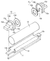
図2は加熱定着装置6の途中部分省略の正面模型図、図3は同じく途中部分省略の縦断正面模型図、図4は図2の(4)−(4)線に沿う拡大横断面模型図である。図5は装置の分解斜視模型図、図6は加熱ユニットの分解斜視模型図である。
FIG. 2 is a front model view of the
9は加熱ユニット(定着部材)である。20は加圧部材(加圧回転体:ニップ形成手段)としての弾性加圧ローラである。この加熱ユニット9と加圧ローラ20とを装置筐体(板金フレーム)30の左右の側板31間に上下にほぼ並行に保持させて、両者の圧接により加熱ニップ部としての定着ニップ部Nを形成させている。
加熱ユニット9は、
a:耐熱性・剛性を有する横長の断熱ステイホルダー12
b:この断熱ステイホルダー12の下面に、該部材の幅方向に沿って設けた凹溝部12a(図4)に嵌め入れて固定支持させた、通電により発熱するヒータ(加熱体)11
c:ヒータ11を固定支持させた断熱ステイホルダー12にルーズに外嵌させた、加熱部材としての可撓性を有する円筒状(エンドレス)の定着ベルト10
d:断熱ステイホルダー12の左右両端側の外方延長部12bにそれぞれ装着した、定着ベルト10の幅方向(母線方向)への寄り移動を規制する規制手段としてのフランジ部材15
等の組み立て体(アセンブリ)である。
The
a: Horizontal heat insulating
b: A heater (heating body) 11 that generates heat by energization, which is fitted and fixedly supported on a lower surface of the heat insulating
c: A cylindrical (endless) fixing
d:
It is an assembly (assembly).
加圧部材としての弾性加圧ローラ20は、芯金21と、芯金21の外側にシリコンゴムやフッ素ゴム等の耐熱ゴムあるいはシリコンゴムを発泡して形成された弾性層22からなる。弾性層22の上にPFA、PTFE、FEP等の離型性層23を形成してあってもよい。
The
装置筐体30の左右の側板31にはそれぞれ上辺側を開放口部にした、幅Lbの、縦長の嵌合用溝31aを同形(左右対称)に形成してある。その各嵌合用溝31a内の底部に対して、PEEK・PPS・液晶ポリマー等の耐熱性樹脂よりなる軸受け部材32あるいはベアリングを、嵌合部32aを係合させて装着してある。そしてこの左右の軸受け部材32にそれぞれ加圧ローラ芯金21の左右端部を支持させることで、加圧ローラ20を左右の側板31間に回転自在に保持させてある。
The left and
加熱ユニット9については、その左右のフランジ部15の後述する固定フランジ(第2の規制部材)15Bにそれぞれ具備させた縦方向嵌合部15cを上記の左右の側板31の嵌合用溝31aの縁部に係合させることで、加圧ローラ20の上側において左右の側板31間に配設してある。上記の縦方向嵌合部15cと嵌合用溝31aは加熱ユニット9を左右の側板31間において加圧ローラ20の方向にスライド案内するガイドの役割をしている。
As for the
そして、左右の固定フランジ15Bの加圧部15dと不動のバネ受け部材40との間に加圧バネ17を縮設することで加熱ユニット9を所定の加圧力をもって加圧ローラ20の上面に対して定着ベルト10の弾性と加圧ローラ20の弾性に抗して押圧させて所定幅の定着ニップ部Nを形成させている。定着ニップ部Nにおいては加熱ユニット9の加圧ローラ20に対する加圧により定着ベルト10がヒータ11を保持させた断熱ステイホルダー12の下面と弾性加圧ローラ20の上面との間に挟まれて、断熱ステイホルダー12の下面に倣って撓み、定着ベルト10の内面が断熱ステイホルダー12の下面およびヒータ11の下面の扁平面に密着した状態になる。
Then, the
Gは加圧ローラ20の芯金21の一端部に固着して配設した駆動ギアである。この駆動ギアGに駆動部Mから回転力が伝達されて、加圧ローラ20が図4において矢印の反時計方向に所定の回転速度にて回転駆動される。この加圧ローラ20の回転駆動に伴って定着ニップ部Nにおける該加圧ローラ20と加熱ユニット9側の定着ベルト10との摩擦力で定着ベルト10に回転力が作用して、該定着ベルト10がその内面がヒータ11の下面に密着して摺動しながら断熱ステイホルダー12の外回りを図4において時計方向に加圧ローラ20の回転に従動して回転状態になる(加圧ローラ駆動式)。
G is a drive gear that is fixedly disposed at one end of the
定着ベルト10は内部のヒータ11および断熱ステイホルダー12に摺擦しながら回転するため、ヒータ11および断熱ステイホルダー12と定着ベルト10の間の摩擦抵抗を小さく抑える必要がある。このためヒータ11および断熱ステイホルダー12の表面に耐熱性グリース等の潤滑剤を少量介在させてある。これにより定着ベルト10はスムーズに回転することが可能となる。
Since the fixing
ヒータ11は、記録材P上のトナー像Tを溶融、定着させる定着ニップ部Nの加熱を行う。
The
加圧ローラ20の回転による定着ベルト10の回転がなされ、ヒータ11に対する通電がなされて該ヒータ11の温度が所定の温度に立ち上がって温調された状態において、未定着トナー像Tを担持した記録材Pが耐熱性の定着入口ガイド24に沿って定着ニップ部Nの定着ベルト10と加圧ローラ20との間に搬送される。そしてその記録材Pが定着ニップ部Nを挟持搬送されることで、未定着トナー像Tが定着ベルト10を介してヒータ11の熱で加熱されて熱定着される。定着ニップ部Nを通過した記録材Pは定着ベルト10の外面から分離して不図示の耐熱性の定着排紙ガイドに案内されて不図示の排出トレイ上に排出される。
The fixing
a)定着ベルト10
エンドレスベルトとしての定着ベルト10は熱容量の小さな、可撓性のあるスリーブである。より具体的には、クイックスタートを可能にするために総厚500μm以下の厚みで耐熱性、高熱伝導性を有するステンレス、Al、Ni、Cu、Zn等の金属部材を単独あるいは合金部材を基層としたスリーブである。また、長寿命の加熱定着装置を構成するために充分な強度を持ち、耐久性に優れた金属製スリーブとして、総厚30μm以上の厚みが必要である。よって定着ベルト10の総厚みとしては30μm以上500μm以下が最適である。
a) Fixing
The fixing
さらに、オフセット防止や記録材の分離性を確保するために表層にはPTFE(ポリテトラフルオロエチレン)、PFA(テトラフルオロエチレンパーフルオロアルキルビニルエーテル共重合体、FEP(テトラフルオロエチレンヘキサフルオロプロピレン共重合体)、ETFE(エチレンテトラフルオロエチレン共重合体)、CTFE(ポリクロロトリフルオロエチレン)、PVDF(ポリビニリデンフルオライド)等のフッ素樹脂、シリコーン樹脂等の離型性の良好な耐熱樹脂を混合ないし単独で被覆したものである。被覆の方法としては、金属製スリーブ基材の外面をエッチング処理した後に上記離型性層をディッピング、粉体スプレー等の塗布によるものや、あるいはチューブ状に形成されたものを金属製スリーブの表面に被せる方式のものであっても良い。または、金属製スリーブ基材の外面をブラスト処理した後に、接着剤であるプライマ層を塗布し、上記離型性層を被覆する方法であっても良い。 Furthermore, in order to prevent offset and ensure separation of the recording material, the surface layer has PTFE (polytetrafluoroethylene), PFA (tetrafluoroethylene perfluoroalkyl vinyl ether copolymer, FEP (tetrafluoroethylene hexafluoropropylene copolymer). ), ETFE (ethylene tetrafluoroethylene copolymer), CTFE (polychlorotrifluoroethylene), PVDF (polyvinylidene fluoride), and other heat-resistant resins with good releasability such as silicone resins are mixed or used alone As the coating method, the outer surface of the metal sleeve base material was etched, and then the release layer was applied by dipping, powder spraying, or the like, or formed into a tube shape. One that covers the surface of a metal sleeve May be of. Or, after blasting the outer surface of the metallic sleeve substrate, a primer layer is an adhesive agent is applied, may be a method of coating said release layer.
また、ヒータ11と接触する金属製スリーブ内面に潤滑性の高いフッ素樹脂層、ポリイミド層、ポリアミドイミド層等を形成してあっても良い。
Further, a highly lubricious fluororesin layer, polyimide layer, polyamideimide layer or the like may be formed on the inner surface of the metal sleeve in contact with the
b)ヒータ11
記録材P上のトナー像Tを溶融、定着させる定着ニップ部Nの加熱を行うヒータ11は、例えば、アルミナ、AlN(チッ化アルミ)等の高絶縁性のセラミックス基板やポリイミド、PPS、液晶ポリマー等の耐熱性樹脂基板の表面に長手方向に沿って、例えばAg/Pd(銀パラジウム)、RuO2、Ta2N等の通電発熱抵抗層をスクリーン印刷等により、厚み10μm程度、幅1〜5mm程度の線状もしくは細帯状に塗工して形成した通電加熱用部材である。図7はそのようなヒータ(セラミックヒータ)11の一例の概略構成図である。
b)
The
a:横長のアルミナ・窒化アルミニウム(AlN)・炭化ケイ素等の高絶縁性のセラミックスでできたセラミック基板(ヒータ基板)11a、
b:上記セラミック基板11aの表面側に長手(幅方向)に沿ってスクリーン印刷等により、厚み10μm程度、幅1〜5mm程度の線状もしくは細帯状に塗工し焼成して形成した、例えばAg/Pd(銀パラジウム)、RuO2、Ta2N等の通電発熱抵抗層11b、
c:上記通電発熱抵抗層11bの長手方向両端部に電気的に導通させて設けた、Ag/Pt(銀・白金)で形成された電極部11c、
d:通電発熱抵抗層11bの表面に設けた、電気的に絶縁し、金属製定着ベルト10との摺擦に耐えることが可能な薄層のガラスコートやフッ素樹脂コート等の絶縁保護層11d、
e:セラミック基板11aの裏面(背面)側に設けたサーミスタ等の温度検知素子14、
等からなる。
a: Ceramic substrate (heater substrate) 11a made of highly insulating ceramics such as horizontally long alumina, aluminum nitride (AlN), silicon carbide, etc.
b: formed on the surface side of the
c: an
d: an insulating
e: a
Etc.
上記のヒータ11は絶縁保護層11dを設けた側が表面側であり、絶縁保護層11dの面に定着ベルト10が摺動する。このヒータ11を、断熱ステイホルダー12の下面に、該部材の長手に沿って設けた凹溝部12a(図4)に嵌め入れて耐熱性接着剤で接着して保持させてある。
In the
51は給電用コネクタであり、断熱ステイホルダー12に固定支持させたヒータ11の電極部11c部分に嵌着され、電極部11cにそれぞれ給電用コネクタ側の電気接点が接触状態になる。52は商用電源(AC)、53はトライアック、54は電力(通電)制御手段(CPU)である(ACライン)。ヒータ11は、商用電源52から、トライアック53を介して電極部11c間に給電されることで通電発熱抵抗層11bの発熱で迅速急峻に昇温する。
そのヒータ11の昇温が温度検知体である温度検知素子14により検知され、その検知温度の電気的アナログ情報がアナログデジタル変換回路(A/D変換回)55に入力し、デジタル化されて電力制御手段54に入力する。温度検知素子14から温度制御部へのDC通電は不図示のDC通電部およびDC電極部を介して不図示のコネクタにより達成している。
The temperature rise of the
温度検知素子14の信号に応じて、ヒータ11の長手方向端部にある電極部11cから通電発熱抵抗層11bに印加される電圧のデューティー比や波数等を適切に制御することで、定着ニップ部N内での温調温度を略一定に保ち、記録材P上のトナー像Tを定着するのに必要な加熱を行う。すなわち、温度検知素子14の検知温度に応じたデジタル情報が入力される電力制御手段54は、温度検知素子14の検知温度が目標温度から所定幅内の値になるよう商用電源52から通電発熱抵抗層11bへの通電を制御するようになっている。
By appropriately controlling the duty ratio, wave number, etc. of the voltage applied from the
電力制御手段54による商用電源52から通電発熱抵抗層11bへの通電の制御として、商用電源52から出力される交流電源の半波周期毎に商用電源52から通電発熱抵抗層11bへの通電に供される位相範囲を温度検知素子14の検知温度に応じて変更するという位相制御、或いは、前記半波周期毎に温度検知素子14の検知温度に応じて商用電源52から通電発熱抵抗層11bへの通電を導通又は遮断のいずれか一方に切り換えるという波数制御等が採用されている。
As control of energization from the
ヒータ基板11aとして耐摩耗性に優れ、熱伝導性の良好なAlN等を用いた場合には通電発熱抵抗層11bを上記基板に対して定着ニップ部Nと反対側に形成してあっても良い。
When AlN or the like having excellent wear resistance and good thermal conductivity is used as the
c)断熱ステイホルダー12
断熱ステイホルダー12は、ヒータ11を支持する役目、定着ベルト10の回転案内部材の役目、加圧部材の役目、定着ニップ部Nと反対方向への放熱を防ぐための断熱部材の役目等をしている、剛性・耐熱性・断熱性の部材であり、液晶ポリマー、フェノール樹脂、PPS、PEEK等により形成されている。
c)
The heat insulating
本実施例では、断熱ステイホルダー12の定着ニップ部Nの下流部を加圧ローラ20側に突出させて高さ1.0mmの凸形状部K(図4、定着ベルトの曲率を変えるためのアゴ部)とした。これは、この凸形状部Kにより定着ベルト10の回転形状を変え、記録材Pと定着ベルト10を曲率分離させるためのものである。
In this embodiment, the downstream portion of the fixing nip portion N of the heat insulating
d)フランジ部材15
断熱ステイホルダー12の左右両端部側にそれぞれ装着されて、記録材上の画像をニップ部にて加熱するエンドレスベルトである定着ベルト10の幅方向への寄り移動を規制する規制手段としてのフランジ部材15は、定着ベルト10と所定距離隔てて設けられ定着ベルト10の寄りに伴い定着ベルト10の端面と突き当たることにより従動回転自在な平板状の回転体としての無端のリング形状または円盤形状である第1の規制部材(以下、従動リング(摺動フランジ)と記す)15Aと、定着ベルト10による従動リング15Aの幅方向への移動を規制する実質的に回転不可に固定された固定体である第2の規制部材(以下、固定フランジ(と記す)15Bとからなっている。
d)
A flange member that is mounted on each of the left and right ends of the heat insulating
図8は固定フランジ15Bの形状を示す6面図(外面図、内面図、左側面図、右側面図、上面図、底面図)、図9は従動リング15Aの斜視図、図10は固定フランジ15Bと従動リング15Aの断面図である。
8 is a six-side view (outside view, inside view, left side view, right side view, top view, bottom view) showing the shape of the fixing
a:固定フランジ15B
第2の規制部材としての固定フランジ15Bは、PPS、液晶ポリマー、フェノール樹脂等の耐熱樹脂により形成されており、その形状はキャップ形状であり、第1の規制部材としての従動リング15Aが挿入可能な内径を有した挿入部15aを内面側に有している。またこの内径は、定着ベルト10の外周形状がニップを作ることによって変形した場合でも、図4のように、定着ベルト10の外周面が挿入部15aの内周面に接触しないように十分な大きさを有している。
a:
The fixing
従動リング15Aの規制部材としての固定フランジ15Bは従動リング15Aを幅方向で規制すると共に、従動リング15Aの回転位置を規制している。
The fixed
固定フランジ15Bは断熱ステイホルダー12の左右両端側の外方延長部12bにそれぞれ嵌着し、その固定フランジ15Bの縦方向嵌合部15cを装置筐体30の側板31の嵌合用溝31aに係合させて側板31に装着する。これにより、固定フランジ15Bで従動リング15Aの長手方向への移動を規制している。
The fixing
また、挿入部15aの一部をヒータ11と干渉しないように15bのように切り欠いているが、その切り欠き部15bの幅は、従動リング15Aの外径よりも小さくなるようにしている。これにより挿入部15a内での従動リング15Aの回転位置を規制している。すなわち挿入部15aの定着ニップ部側を切り欠くことにより、定着ニップ部長手方向において挿入部15aと定着ニップ領域をオーバーラップさせることができる。
Further, a part of the
b:従動リング15A
第1の規制部材としての従動リング15Aは、PPS、液晶ポリマー、フェノール樹脂等の耐熱樹脂より形成されている。
b:
The driven
その形状は、図9・図10に示すとおりに、リング型の円盤であり、外径Loは固定フランジ15の挿入部15aの内径よりも小さく、切り欠き部15bよりも大きい。また内径Liはヒータ11に干渉しないような大きさである。この内径Li内に断熱ステイホルダー12の外方延長部12bが貫通位置して従動リング15Aと断熱ステイホルダー12の外方延長部12bとは干渉しない。
As shown in FIGS. 9 and 10, the shape is a ring-shaped disk, and the outer diameter Lo is smaller than the inner diameter of the
この無端のリング形状または円盤形状の第1の規制部材としての従動リング15Aは回転体である定着ベルト10の母線方向端部に対向する面が平面のみである。
The endless ring-shaped or disk-shaped driven
従動リング15Aは定着ベルト10の幅方向の端部を規制すると共に、定着ベルト10が幅方向の力を受けて寄り、従動リング15Aに突き当たると同時に従動リング15Aは定着ベルト10から駆動力を受け、定着ベルト10と共に回転することで、定着ベルト10の端部が摺擦することを防止し、且つ定着ベルト10の回転形状を拘束しないため、定着ベルト10に負荷を与えず定着ベルト10の端部の破損を防止する。
The driven
また、寄り方向とは逆の端部では、定着ベルト10と従動リング15Aは当接しないため、従動リング15Aは回転しないが、平面形状であるため定着ベルト10の側面に摺擦する部分を持たないため、定着ベルト10の表層を傷つけることも無い。
Further, at the end opposite to the shift direction, the fixing
また、本例に於いては、定着ベルト10と従動リング15Aの摩擦係数μ1と従動リング15Aと固定フラン15Bの摩擦係数μ2が[μ1>μ2]となるように設定した。これにより、定着ベルト10が寄り移動して従動リング15Aに突き当たった時に、従動リング15Aが確実に定着ベルト10に従動するようにした。
In this example, the friction coefficient μ1 of the fixing
上記のように、定着ベルト10の幅方向への寄りを規制する規制手段15は、定着ベルト10と所定距離隔てて設けられ定着ベルト10の寄りに伴い定着ベルト10の端面と突き当たることにより従動回転自在な平板状の回転体である従動リング15Aを有することで、定着ベルト10の回転形状を拘束せず、そのため定着ベルト10の回転形状の曲率が大きく変っても、その部分で従動リング15Aより負荷を受ける事が無いため、定着ベルト10の破損を起こさせない。また、定着ベルト表面に接触する部分がないため、定着ベルト表層を傷つけることなく、表層剥れを起こさせない。且つ定着ベルト10が寄って定着ベルト端部が従動リング15Aに突き当たったときにのみ定着ベルトから従動リング15Aへ駆動力が伝わり、従動リング15Aが定着ベルト10と従動し端部の破損を起こさせない。
As described above, the regulating means 15 that regulates the deviation in the width direction of the fixing
また、定着ベルト10と従動リング15Aの摩擦係数μ1と従動リング15Aと固定フラン15Bの摩擦係数μ2が[μ1>μ2]となるように設定することで、定着ベルト10が寄り力を受けて寄り、従動リング15Aに突き当たった場合に、定着ベルト10と従動リング15Aは従動し、従動リング15Aと固定フラン15Bとは摺動する。定着ベルト10と従動リング15Aが従動することで、定着ベルト10の母線方向端部には摺動による負荷がかかることがないため、定着ベルト10の破損を起こさせない。
Further, by setting the friction coefficient μ1 of the fixing
定着ベルト10の寄り方向と反対側の端部では、定着ベルト10と従動リング15Aが当接していないため、定着ベルト10と従動リング15Aは従動しないが、平面であるために、定着ベルト表層に接触しないため定着ベルト表層の削れを引き起こさない。
Since the fixing
このように、フリーニップ系のベルト定着で、金属ベルトを使用する場合でも、ニップの形状に寄らず簡単な構成で、ベルト端部の破損を起こさせずベルト寄りを規制することができる。 In this way, even when a metal belt is used for free nip belt fixing, the belt deviation can be regulated without causing damage to the belt end portion with a simple configuration regardless of the shape of the nip.
〈その他〉
1)定着ベルト10の端部を規制するフランジ部材15(15A+15B)は、定着ベルト10の寄り移動方向を一方向化させ、その寄り移動方向の一端部側だけに配設する装置構成にすることもできる。
<Others>
1) The flange member 15 (15A + 15B) that regulates the end portion of the fixing
2)ヒータ11は励磁コイルアセンブリの発生磁場の作用で電磁誘導発熱する鉄板片などの電磁誘導発熱性部材にすることもできる。
2) The
また、定着ベルト10自体を電磁誘導発熱させる画像加熱装置に適用することもできる。
Further, it can be applied to an image heating apparatus in which the fixing
3)本例では、回転体として定着ベルト10を挙げたが、加圧部材側にベルトがある加熱定着装置でも同様である。
3) In this example, the fixing
4)本発明の画像加熱装置は画像加熱定着装置としてばかりではなく、その他、例えば、画像を担持した記録材を加熱してつや等の表面性を改質する画像加熱装置、仮定着処理する画像加熱装置等として広く使用出来ることは勿論である。 4) The image heating apparatus of the present invention is not only an image heating and fixing apparatus, but also, for example, an image heating apparatus that modifies the surface properties such as gloss by heating a recording material carrying an image, and an image heating that performs a hypothetical process. Of course, it can be widely used as an apparatus or the like.
本発明は上述の例にとらわれるものではなく、技術思想が同じ他の構成も含むものである。 The present invention is not limited to the above-described example, and includes other configurations having the same technical idea.
10:定着ベルト(エンドレスベルト)、11:加熱用ヒータ、12:耐熱ステイホルダー、15:固定フランジ(第2の規制部材)、20:加圧ローラ、50:従動リング(第1の規制部材:平板状の回転体)、N:定着ニップ部、P:記録材、T:トナー像 10: fixing belt (endless belt), 11: heater for heating, 12: heat-resistant stay holder, 15: fixing flange (second regulating member), 20: pressure roller, 50: driven ring (first regulating member: first regulating member: Flat rotating body), N: fixing nip, P: recording material, T: toner image
Claims (3)
ニップ部を形成するニップ形成手段と、を有する画像加熱装置において、
前記ベルトの寄りに伴い前記ベルトの端面と突き当たることにより従動回転自在な平板状の回転部材と、
前記ベルトの幅方向において前記ベルトと所定距離隔てた位置に固定して設けられており、前記回転部材を収納するための内周面を備えた固定部材と、を有し、
前記ベルトの端面が前記回転部材に突きあたった状態で、前記回転部材は前記ベルトの外周面から離れているとともに、前記固定部材の内周面は前記ベルトの外周面から離れていることを特徴とする画像加熱装置。 An image heating apparatus comprising an endless belt for heating an image on a recording material at a nip portion, and a nip forming means for forming said nip portion between said belt,
A plate-shaped rotary member freely rotated by impinging with the end face of the belt with the deviation of the belt,
A fixing member provided at a position spaced apart from the belt by a predetermined distance in the width direction of the belt, and having an inner peripheral surface for storing the rotating member;
The rotating member is separated from the outer peripheral surface of the belt while the end surface of the belt is in contact with the rotating member, and the inner peripheral surface of the fixing member is separated from the outer peripheral surface of the belt. An image heating apparatus.
Priority Applications (2)
| Application Number | Priority Date | Filing Date | Title |
|---|---|---|---|
| JP2005011712A JP4621033B2 (en) | 2005-01-19 | 2005-01-19 | Image heating device |
| US11/275,516 US7660553B2 (en) | 2005-01-19 | 2006-01-11 | Image heating apparatus |
Applications Claiming Priority (1)
| Application Number | Priority Date | Filing Date | Title |
|---|---|---|---|
| JP2005011712A JP4621033B2 (en) | 2005-01-19 | 2005-01-19 | Image heating device |
Publications (3)
| Publication Number | Publication Date |
|---|---|
| JP2006201370A JP2006201370A (en) | 2006-08-03 |
| JP2006201370A5 JP2006201370A5 (en) | 2007-12-13 |
| JP4621033B2 true JP4621033B2 (en) | 2011-01-26 |
Family
ID=36696896
Family Applications (1)
| Application Number | Title | Priority Date | Filing Date |
|---|---|---|---|
| JP2005011712A Active JP4621033B2 (en) | 2005-01-19 | 2005-01-19 | Image heating device |
Country Status (2)
| Country | Link |
|---|---|
| US (1) | US7660553B2 (en) |
| JP (1) | JP4621033B2 (en) |
Families Citing this family (34)
| Publication number | Priority date | Publication date | Assignee | Title |
|---|---|---|---|---|
| JP4655632B2 (en) * | 2005-01-12 | 2011-03-23 | 富士ゼロックス株式会社 | Charging device, cartridge using the same, and image forming apparatus |
| KR20080003542A (en) * | 2006-07-03 | 2008-01-08 | 삼성전자주식회사 | Image fixing device for electro-photographic image forming apparatus |
| JP5446063B2 (en) * | 2006-09-20 | 2014-03-19 | 株式会社リコー | Fixing apparatus and image forming apparatus |
| JP2008261953A (en) | 2007-04-10 | 2008-10-30 | Ricoh Co Ltd | Image forming apparatus |
| KR101511499B1 (en) * | 2007-10-24 | 2015-04-16 | 삼성전자주식회사 | Fusing device and image forming apparatus having the same |
| US7831165B2 (en) * | 2008-03-27 | 2010-11-09 | Seiko Epson Corporation | Fixing device and image forming apparatus equipped with the fixing device |
| JP5499800B2 (en) * | 2010-03-17 | 2014-05-21 | 株式会社リコー | Fixing apparatus and image forming apparatus |
| JP5216814B2 (en) * | 2010-06-29 | 2013-06-19 | 京セラドキュメントソリューションズ株式会社 | Fixing unit and image forming apparatus incorporating fixing unit |
| JP5555098B2 (en) * | 2010-08-25 | 2014-07-23 | キヤノン株式会社 | Image heating device |
| JP5884299B2 (en) * | 2011-05-31 | 2016-03-15 | ブラザー工業株式会社 | Fixing device |
| JP5773151B2 (en) * | 2011-08-17 | 2015-09-02 | 株式会社リコー | Fixing apparatus and image forming apparatus |
| JP5737629B2 (en) * | 2011-12-26 | 2015-06-17 | 株式会社リコー | Fixing apparatus and image forming apparatus |
| JP5928783B2 (en) | 2012-01-11 | 2016-06-01 | 株式会社リコー | Fixing apparatus and image forming apparatus |
| JP5737520B2 (en) * | 2012-01-13 | 2015-06-17 | 株式会社リコー | Fixing apparatus and image forming apparatus |
| JP5582655B2 (en) * | 2012-01-30 | 2014-09-03 | 京セラドキュメントソリューションズ株式会社 | Fixing apparatus and image forming apparatus having the same |
| JP6103679B2 (en) * | 2012-02-09 | 2017-03-29 | 株式会社リコー | Fixing apparatus and image forming apparatus |
| JP6094712B2 (en) * | 2012-02-09 | 2017-03-15 | 株式会社リコー | Fixing apparatus and image forming apparatus |
| JP5331910B2 (en) * | 2012-02-21 | 2013-10-30 | 京セラドキュメントソリューションズ株式会社 | Fixing apparatus and image forming apparatus having the same |
| JP5966443B2 (en) * | 2012-03-01 | 2016-08-10 | 株式会社リコー | Fixing apparatus and image forming apparatus |
| JP6175821B2 (en) * | 2013-03-14 | 2017-08-09 | 株式会社リコー | Fixing apparatus and image forming apparatus |
| JP6229422B2 (en) * | 2013-10-10 | 2017-11-15 | 株式会社リコー | Fixing apparatus and image forming apparatus |
| JP6497147B2 (en) * | 2015-03-17 | 2019-04-10 | 株式会社リコー | Fixing apparatus and image forming apparatus |
| JP6102973B2 (en) * | 2015-04-24 | 2017-03-29 | 株式会社リコー | Fixing apparatus and image forming apparatus |
| EP3098665B1 (en) | 2015-05-08 | 2021-03-10 | Canon Kabushiki Kaisha | Image forming apparatus |
| JP6426116B2 (en) * | 2016-04-28 | 2018-11-21 | 株式会社リコー | Fixing device and image forming apparatus |
| JP6625073B2 (en) | 2017-01-20 | 2019-12-25 | キヤノン株式会社 | Image heating device |
| JP6906972B2 (en) | 2017-02-06 | 2021-07-21 | キヤノン株式会社 | Image heating device |
| JP6299997B2 (en) * | 2017-02-27 | 2018-03-28 | 株式会社リコー | Fixing apparatus and image forming apparatus |
| KR20190142635A (en) * | 2018-06-18 | 2019-12-27 | 휴렛-팩커드 디벨롭먼트 컴퍼니, 엘.피. | Endless Fuser Belt Supported by Rotation Member and Washer |
| JP2020016824A (en) * | 2018-07-27 | 2020-01-30 | キヤノン株式会社 | Fixing device and image forming device |
| JP7187258B2 (en) * | 2018-10-23 | 2022-12-12 | キヤノン株式会社 | Fixing device |
| JP6859994B2 (en) * | 2018-11-12 | 2021-04-14 | 株式会社リコー | Fixing device and image forming device |
| JP7360621B2 (en) * | 2019-01-25 | 2023-10-13 | 株式会社リコー | Belt device, transfer device, and image forming device |
| US20220357650A1 (en) * | 2021-05-07 | 2022-11-10 | Entegris, Inc. | Metal plating with lubricant |
Citations (4)
| Publication number | Priority date | Publication date | Assignee | Title |
|---|---|---|---|---|
| JPH0642611A (en) * | 1991-01-22 | 1994-02-18 | Taiho Kogyo Co Ltd | Bearing device for automatic transmission |
| JPH08170595A (en) * | 1994-12-16 | 1996-07-02 | Matsushita Refrig Co Ltd | Hermetic compressor |
| JP2002323821A (en) * | 2001-02-20 | 2002-11-08 | Canon Inc | Image heating device |
| JP2006195059A (en) * | 2005-01-12 | 2006-07-27 | Fuji Xerox Co Ltd | Charging device, cartridge using the device, and image forming apparatus |
Family Cites Families (4)
| Publication number | Priority date | Publication date | Assignee | Title |
|---|---|---|---|---|
| DE69117806T2 (en) | 1990-06-11 | 1996-08-22 | Canon Kk | Heater with continuous film |
| JP2884714B2 (en) | 1990-06-11 | 1999-04-19 | キヤノン株式会社 | Image heating device |
| JP3582269B2 (en) | 1996-12-25 | 2004-10-27 | 富士ゼロックス株式会社 | Fixing device |
| JP2004144833A (en) * | 2002-10-22 | 2004-05-20 | Canon Inc | Heating device |
-
2005
- 2005-01-19 JP JP2005011712A patent/JP4621033B2/en active Active
-
2006
- 2006-01-11 US US11/275,516 patent/US7660553B2/en active Active
Patent Citations (4)
| Publication number | Priority date | Publication date | Assignee | Title |
|---|---|---|---|---|
| JPH0642611A (en) * | 1991-01-22 | 1994-02-18 | Taiho Kogyo Co Ltd | Bearing device for automatic transmission |
| JPH08170595A (en) * | 1994-12-16 | 1996-07-02 | Matsushita Refrig Co Ltd | Hermetic compressor |
| JP2002323821A (en) * | 2001-02-20 | 2002-11-08 | Canon Inc | Image heating device |
| JP2006195059A (en) * | 2005-01-12 | 2006-07-27 | Fuji Xerox Co Ltd | Charging device, cartridge using the device, and image forming apparatus |
Also Published As
| Publication number | Publication date |
|---|---|
| US7660553B2 (en) | 2010-02-09 |
| JP2006201370A (en) | 2006-08-03 |
| US20060165446A1 (en) | 2006-07-27 |
Similar Documents
| Publication | Publication Date | Title |
|---|---|---|
| JP4621033B2 (en) | Image heating device | |
| JP3814542B2 (en) | Image heating device | |
| JP6086100B2 (en) | Fixing apparatus and image forming apparatus | |
| JP5777668B2 (en) | Image heating device | |
| JP2009288284A (en) | Image heating apparatus and image forming apparatus with the same | |
| JP2006084821A (en) | Heat fixing apparatus | |
| JP6282141B2 (en) | Fixing device | |
| JP2008299205A (en) | Heater and image heating device | |
| JP2007322888A (en) | Fixing device and image forming apparatus | |
| JP2004085698A (en) | Image forming apparatus | |
| JP2007047674A (en) | Image forming apparatus | |
| JP2004013045A (en) | Image heating device and image forming apparatus | |
| JP2008275756A (en) | Heat fixing device | |
| JP2017009949A (en) | Image forming device | |
| JP2010054821A (en) | Image heating apparatus | |
| JP2002311749A (en) | Image forming device | |
| JP2017009948A (en) | Image forming device | |
| JP3958108B2 (en) | Image forming apparatus | |
| JP2004126328A (en) | Image forming apparatus | |
| JP3799296B2 (en) | Image forming apparatus | |
| JP4944429B2 (en) | Fixing device | |
| JP2003287978A (en) | Fixing device | |
| JP2003295683A (en) | Image forming apparatus | |
| JP2004144971A (en) | Heating device | |
| JP2015166794A (en) | image forming apparatus |
Legal Events
| Date | Code | Title | Description |
|---|---|---|---|
| A521 | Request for written amendment filed |
Free format text: JAPANESE INTERMEDIATE CODE: A523 Effective date: 20071029 |
|
| A621 | Written request for application examination |
Free format text: JAPANESE INTERMEDIATE CODE: A621 Effective date: 20071029 |
|
| A131 | Notification of reasons for refusal |
Free format text: JAPANESE INTERMEDIATE CODE: A131 Effective date: 20100615 |
|
| A977 | Report on retrieval |
Free format text: JAPANESE INTERMEDIATE CODE: A971007 Effective date: 20100615 |
|
| A521 | Request for written amendment filed |
Free format text: JAPANESE INTERMEDIATE CODE: A523 Effective date: 20100806 |
|
| TRDD | Decision of grant or rejection written | ||
| A01 | Written decision to grant a patent or to grant a registration (utility model) |
Free format text: JAPANESE INTERMEDIATE CODE: A01 Effective date: 20101026 |
|
| A01 | Written decision to grant a patent or to grant a registration (utility model) |
Free format text: JAPANESE INTERMEDIATE CODE: A01 |
|
| A61 | First payment of annual fees (during grant procedure) |
Free format text: JAPANESE INTERMEDIATE CODE: A61 Effective date: 20101029 |
|
| FPAY | Renewal fee payment (event date is renewal date of database) |
Free format text: PAYMENT UNTIL: 20131105 Year of fee payment: 3 |
|
| R150 | Certificate of patent or registration of utility model |
Ref document number: 4621033 Country of ref document: JP Free format text: JAPANESE INTERMEDIATE CODE: R150 Free format text: JAPANESE INTERMEDIATE CODE: R150 |
|
| RD03 | Notification of appointment of power of attorney |
Free format text: JAPANESE INTERMEDIATE CODE: R3D03 |