JP4620817B2 - Image processing apparatus and image processing method - Google Patents
Image processing apparatus and image processing method Download PDFInfo
- Publication number
- JP4620817B2 JP4620817B2 JP13405799A JP13405799A JP4620817B2 JP 4620817 B2 JP4620817 B2 JP 4620817B2 JP 13405799 A JP13405799 A JP 13405799A JP 13405799 A JP13405799 A JP 13405799A JP 4620817 B2 JP4620817 B2 JP 4620817B2
- Authority
- JP
- Japan
- Prior art keywords
- image data
- error diffusion
- value
- processing
- scan
- Prior art date
- Legal status (The legal status is an assumption and is not a legal conclusion. Google has not performed a legal analysis and makes no representation as to the accuracy of the status listed.)
- Expired - Fee Related
Links
Images


Classifications
-
- B—PERFORMING OPERATIONS; TRANSPORTING
- B41—PRINTING; LINING MACHINES; TYPEWRITERS; STAMPS
- B41J—TYPEWRITERS; SELECTIVE PRINTING MECHANISMS, i.e. MECHANISMS PRINTING OTHERWISE THAN FROM A FORME; CORRECTION OF TYPOGRAPHICAL ERRORS
- B41J2/00—Typewriters or selective printing mechanisms characterised by the printing or marking process for which they are designed
- B41J2/005—Typewriters or selective printing mechanisms characterised by the printing or marking process for which they are designed characterised by bringing liquid or particles selectively into contact with a printing material
- B41J2/01—Ink jet
- B41J2/21—Ink jet for multi-colour printing
- B41J2/2132—Print quality control characterised by dot disposition, e.g. for reducing white stripes or banding
-
- B—PERFORMING OPERATIONS; TRANSPORTING
- B41—PRINTING; LINING MACHINES; TYPEWRITERS; STAMPS
- B41J—TYPEWRITERS; SELECTIVE PRINTING MECHANISMS, i.e. MECHANISMS PRINTING OTHERWISE THAN FROM A FORME; CORRECTION OF TYPOGRAPHICAL ERRORS
- B41J2/00—Typewriters or selective printing mechanisms characterised by the printing or marking process for which they are designed
- B41J2/485—Typewriters or selective printing mechanisms characterised by the printing or marking process for which they are designed characterised by the process of building-up characters or image elements applicable to two or more kinds of printing or marking processes
- B41J2/505—Typewriters or selective printing mechanisms characterised by the printing or marking process for which they are designed characterised by the process of building-up characters or image elements applicable to two or more kinds of printing or marking processes from an assembly of identical printing elements
- B41J2/51—Typewriters or selective printing mechanisms characterised by the printing or marking process for which they are designed characterised by the process of building-up characters or image elements applicable to two or more kinds of printing or marking processes from an assembly of identical printing elements serial printer type
-
- B—PERFORMING OPERATIONS; TRANSPORTING
- B41—PRINTING; LINING MACHINES; TYPEWRITERS; STAMPS
- B41J—TYPEWRITERS; SELECTIVE PRINTING MECHANISMS, i.e. MECHANISMS PRINTING OTHERWISE THAN FROM A FORME; CORRECTION OF TYPOGRAPHICAL ERRORS
- B41J2/00—Typewriters or selective printing mechanisms characterised by the printing or marking process for which they are designed
- B41J2/52—Arrangement for printing a discrete number of tones, not covered by group B41J2/205, e.g. applicable to two or more kinds of printing or marking process
-
- G—PHYSICS
- G06—COMPUTING; CALCULATING OR COUNTING
- G06K—GRAPHICAL DATA READING; PRESENTATION OF DATA; RECORD CARRIERS; HANDLING RECORD CARRIERS
- G06K15/00—Arrangements for producing a permanent visual presentation of the output data, e.g. computer output printers
- G06K15/02—Arrangements for producing a permanent visual presentation of the output data, e.g. computer output printers using printers
- G06K15/10—Arrangements for producing a permanent visual presentation of the output data, e.g. computer output printers using printers by matrix printers
- G06K15/102—Arrangements for producing a permanent visual presentation of the output data, e.g. computer output printers using printers by matrix printers using ink jet print heads
- G06K15/105—Multipass or interlaced printing
- G06K15/107—Mask selection
Description
【0001】
【発明の属する技術分野】
本発明は、記録ヘッドにおける複数の記録素子間の記録特性のばらつきに起因した濃度ムラを低減して記録媒体に記録を行う画像形成装置、画像形成方法及び画像処理方法に関する。特に、複数の記録ヘッドの取付位置の誤差に起因するモアレなどを低減して記録媒体に記録を行う画像形成装置、画像形成方法及び画像処理方法に関する。
【0002】
【従来の技術】
複数の記録素子を備えた記録ヘッドを用いる装置の一例として、従来より、複数のインクの吐出口を備えた記録ヘッドを用いるインクジェット記録装置が知られている。
【0003】
このような装置では、吐出口の吐出口径のばらつきや吐出方向のばらつきなどによってインクにより形成されるドットの大きさや形成位置がばらつき、印刷された画像に濃度ムラが生じることがある。特に、記録ヘッドをその複数の記録素子の配列方向とは異なる方向、例えば、直交する方向に走査させて記録を行うシリアル型の記録装置では、上述した吐出口径などのばらつきに起因した濃度ムラはスジムラとなって印刷された画像中に現れるため、さらに印刷された画像の品位を低下させる場合がある。
【0004】
このような濃度ムラを補正するため、インクジェット記録方式に従った記録ヘッドを用いて画像形成を行う場合、低階調化処理(2値化処理など)を施した画像データを複数の異なる吐出口から吐出されるインクで1画素、または記録ヘッド1走査に相当するラインからなる画素の画像を形成する方式が提案されている。これは、例えば、記録ヘッドの幅未満の紙送りを行うことにより、1画素を複数の走査(スキャン、パス)で補完することにより実現できる。
【0005】
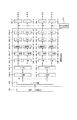
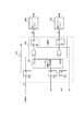
図3は従来のインクジェット記録ヘッド部の並び状況を示す図である。本プリンタは基本4色のCMYKインクで画像を構成している。記録ヘッド部601は各インク色のインクジェットヘッドをそれぞれ2本ずつ搭載しており、図の上部に並んでいるヘッド603(以下、リアヘッドと称する)と、下部に並んでいるヘッド602(以下、フロントヘッドと称する)とが、副走査方向に2.5バンド(バンドとは、インクジェットヘッドが1回の走査で印字するノズル列方向の幅の単位である)の距離に配置されている。
【0006】
図4は図3に示す記録ヘッドを用いるプリンタにおいて、フロントヘッド602とリアヘッド603の印字の重ね状態を示す図である。主走査1回につき、副走査を1回行う。副走査方向への送り量は1バンドであり、フロントヘッド602とリアヘッド603が半バンドずれた状態、つまり半バンド重ねで画像が構成される。ここで、半バンド703はそれぞれフロントヘッド602の図示上半分、リアヘッド603の下半分で形成され、半バンド704はそれぞれフロントヘッド602の下半分、リアヘッド603の上半分で形成される。
【0007】
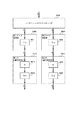
上記プリンタに転送された多値の画像データを2値化し、ヘッド駆動データに変換してノズルからインクを吐出させて印字するまでの処理内容を図5に示し、図に添って処理の流れを説明する。
【0008】
(1) ホストコンピュータから転送された多値の画像データは画像データ記憶装置801に記憶される。ここから1バンドごとにデータが読み出されていく。
【0009】
(2) パレット変換回路802では画像データが各インク色の多値のデータに分解される。以下、黒インクBkについて代表して説明する。
【0010】
(3) γ変換回路803−Kではそれぞれインク色に分解された多値のデータに対しγ変換が行なわれる。
【0011】
(4) ムラ補正回路804−Kにてムラ補正テーブル(多値→多値のルックアップテーブル)によりノズルの特性ばらつきに起因したムラの補正を行う。
【0012】
(5)2値化回路805−Kで誤差拡散法(ED)により多値のデータを2値のデータに変換する。
【0013】
(6) 各色の2値データをフロントヘッド602−K、リアヘッド603−Kのどちらで印字するかをSMS(シーケンシャル・マルチ・スキャン)回路806−Kで決定する。このSMS回路−Kは、あるラスターに注目した時に、画像の左端から最初に現れるドットから順にフロント,リア,フロント,リア,… と交互に割り振るもので、それぞれTMC(Timing Memory Controller)回路807−K1,807−K2に出力される。これにより、隣接するドットを同一のヘッドで印字することがなくなり、ヘッドの駆動周波数の倍速で印字を行うことが可能である。さらに、各ラスターで最初に現れるドットを印字するのは、奇数ラスターの場合はリアヘッド603−K、偶数ラスターの場合はフロントヘッド602−Kで印字する。
【0014】
(7)TMC回路807−K1,807−K2では、各ヘッド602−K,603−Kに対し1バンドのデータをノズル列方向に1列ずつ出力している。ヘッド807−K1,807−K2間のヘッド主走査方向の位置ズレを調整するのが横レジ調値であるが、横レジ調値に応じて1列分のデータの出力タイミングは異なる。
【0015】
(8)PHC(Printer Head間 コネクタ)基板808−K1,808−K2では、ノズル列方向の2値データを、実際に印字を行うノズルに対応させて出力する。ヘッド807−K1,807−K2間のノズル列方向の位置ズレを調整するのが縦レジ調値である。本例におけるヘッドは1344ノズルに加えて上下8ノズルが印字有効ノズルであるので、縦レジ調値は−8〜+8の範囲である。縦レジ調値が±0の場合は中央の1344ノズルを使用するが、縦レジ調値が±1〜8の場合は実際に印字する1344ノズルを中央から1〜8ノズル分ずらしている。この縦レジ調値によって、1344ノズル分のデータを実際に印字を行うノズルに対応させて出力する。
【0016】
(9) 最後に各ノズルの2値のデータを、印字制御装置(Head CPU)809でヘッド駆動データに変換し、インクを吐出させて印字を行う。
【0017】
ここで特に、(5)、(6)の処理を具体的に示しているのが図7である。各インク色に分解され、γ変換、ムラ補正処理(図5の802,803,804)を行った後の多値のデータ(同図A)を誤差拡散マトリックスA(図6Aに示す誤差拡散マトリックスの例)で誤差拡散処理(図7B)を行い2値化を行う(同図C)。なお、図6中*は注目画素を表す。そして、SMS(図5の806)により、フロントヘッドとリアヘッドのどちらで印字するかを決定する(図7D)。そして、図7Eに示すデータがフロントヘッドに送られ、図7Fに示すデータがリアヘッドに送られる。
【0018】
上述の方法によれば、所定領域の画像は2つのヘッドの異なるノズルによって形成されるので、複数のノズルの特性ばらつきに起因する濃度ムラ等を軽減することが出来る。また、画像の繋ぎ目が半バンド単位となるので、バンディングの周期が半分となり、バンディングも目立ちにくくなる。
【0019】
このように、インクジェットヘッドの吐出口に固有の特性に起因して生じる濃度ムラを被記録媒体上に分散させて相対的に濃度ムラを低減する方式は、マルチスキャン(マルチパスとも呼ばれる)方式と呼ばれる。さらに、このマルチスキャン方式において、主に各インク吐出口の使用頻度を均一化することを目的として、各インク吐出口を一定の順序で用いる、所謂シーケンシャルマルチスキャン(SMS)方式も提案されている。
【0020】
【発明が解決しようとする課題】
しかしながら、このようなマルチスキャン方式あるいはシーケンシャルマルチスキャン方式を、捺染装置のように走査範囲が数メートルにおよび、イエロー色、マゼンタ色、シアン色、ブラック色のほか、淡色、特色で構成される大型、多色のカラーインクジェットプリント装置において適用する場合に、次の課題を見いだした。すなわち、本来、理想的な装置を用いて上記方法で記録を行えば、単位記録画素は均等に並ぶはずである。しかしながら、実際の記録装置では、上述のインク吐出口の吐出口径のばらつきや吐出方向のばらつきなどによってインクにより形成されるドットの大きさや形成位置がばらつくほか、複数の記録ヘッド間の機械的な取付精度の誤差により、それぞれの主走査間でレジストレーションの変化が発生してしまう。このために、マルチスキャンで重ねられた単位記録画素間隔の差異が発生し、その結果モアレ効果や半走査間隔のムラが発生する。特に、往復の主走査記録では、記録ヘッドの取付角精度や、吐出口の形状について、往路と復路で差異が発生し、これによる往復ムラが発生する。
【0021】
これは、上記の方法では、複数の走査で形成される印字画像間にある「補完関係」が完全であることに起因していることが、本発明者らの検討により判明した。
【0022】
すなわち、上述の方法では、2回の走査で完成される半バンドの画像は互いに完全に補完する関係にある(以下、それぞれのパスで印字するドットが空間的に補完する関係のことを「補完関係」と呼ぶ。)。このため、各バンド毎にレジストレーションに誤差が生じると、例えば、半ドット分の横レジがずれると、横レジがずれた状態で補完がなされてしまうこととなる。
【0023】
本来、理想的な装置を用いて上記の方法で記録を行えば、図8に示すベタ(均一)の画像は、それぞれの走査で記録される画像を重ねても、ドットが重なることなく均等に並んでいるはずである。図8において、21(黒丸のドット)は第1の走査で印字したものを示し、22(白丸のドット)は第2の走査で印字したものとする。
【0024】
しかしながら、実際の装置では、物理的な精度の誤差によりそれぞれの走査で微妙にレジストレーションが変化してしまうために、それぞれの走査で記録される画像を重ねると、ドット同士が近ずいたり遠くに離れたり、あるいは重なったりしてしまう。例えば、第1の走査に半ドット分の横レジのずれが生じると、図9に示すように、ドット間に粗密が発生したりドットの重なりが生じてしまう。21(黒丸のドット)は第1の走査で印字したものを示し、22(白丸のドット)は第2の走査で印字したものとする。その結果、記録される画像は本来の画像濃度と異なり、濃度むらが発生しこれが大きな問題となっている。すなわち、濃度の濃いバンド(バンドとは、インクジェットヘッドが1回の走査で印字するノズル列方向の幅の単位である)や薄いバンドができ、半バンドむらが生じてしまう。
【0025】
このように、従来のマルチパス印字においては、複数回の走査で画像を形成する際、複数の走査で完成される画像は完全な補完関係にあったため、レジストレーションの変化がそのまま画像のムラとして現れることが、本発明者らの検討によって判明した。
【0026】
本発明は、上記課題を解決するためになされたものであり、マルチスキャン方式による記録において、単位記録画素間隔の差異による濃度差を軽減し、より高品位な画像を高速に記録することができる画像形成装置、画像形成方法及び画像処理方法を提供することを目的とする。
【0027】
また、本発明は、物理的な精度誤差によるレジストレーションが微妙に変化しても、画像濃度が大きく変化せず濃度むらを軽減した均一な画像を形成することが可能な画像形成装置、画像形成方法、及び画像処理法法を提供することを目的とする。
【0028】
【課題を解決するための手段】
上記目的を達成するための本発明は、記録ヘッドの少なくとも2回の走査によって記録媒体の画素領域に画像を形成するために、前記画素領域に対応した入力画像データを処理するための画像処理装置であって、前記入力画像データに基づいて、前記2回の走査のうちの第1の走査に対応した第1の多値画像データと前記2回の走査のうちの第2の走査に対応した第2の多値画像データとを生成するための生成手段と、前記生成手段により生成された第1および第2の多値画像データに誤差拡散処理を行うための誤差拡散処理手段とを有し、前記第1の多値画像データに誤差拡散処理を行うために用いる誤差拡散マトリクスは、前記第2の多値画像データに誤差拡散処理を行うために用いる誤差拡散マトリクスとは異なることを特徴とする。
【0029】
また、本発明は、記録ヘッドの少なくとも2回の走査によって記録媒体の画素領域に画像を形成するために、前記画素領域に対応した入力画像データを処理するための画像処理装置であって、前記入力画像データに基づいて、前記2回の走査のうちの第1の走査に対応した第1の多値画像データと前記2回の走査のうちの第2の走査に対応した第2の多値画像データとを生成するための生成手段と、前記生成手段により生成された第1および第2の多値画像データに誤差拡散処理を実行するための誤差拡散処理手段とを有し、前記誤差拡散処理手段は、前記第1の多値画像データに誤差拡散処理を実行するために用いる閾値とは異なる閾値を用いて前記第2の多値画像データに誤差拡散処理を実行可能であることを特徴とする。
【0031】
また、本発明は、記録ヘッドの第1および第2の走査を含む複数回の走査によって記録媒体上の画素領域に画像を形成するための画像処理を行う画像処理方法であって、前記画素領域に対応した入力画像データに基づいて、前記第1の走査に対応した第1の多値画像データおよび前記第2の走査に対応した第2の多値画像データを生成する生成工程と、前記生成工程により生成された第1および第2の多値画像データに誤差拡散処理を行う誤差拡散処理工程とを有し、前記第1の多値画像データに誤差拡散処理を行うために用いる誤差拡散マトリクスは、前記第2の多値画像データに誤差拡散処理を行うために用いる誤差拡散マトリクスとは異なることを特徴とする。
また、本発明は、記録ヘッドの第1および第2の走査を含む複数回の走査によって記録媒体上の画素領域に画像を形成するための画像処理を行う画像処理方法であって、前記画素領域に対応した入力画像データに基づいて、前記第1の走査に対応した第1の多値画像データおよび前記第2の走査に対応した第2の多値画像データを生成する生成工程と、前記生成工程により生成された第1および第2の多値画像データに誤差拡散処理を行う誤差拡散処理工程とを有し、前記第1の多値画像データに誤差拡散処理を行うために用いる閾値は、前記第2の多値画像データに誤差拡散処理を行うために用いる閾値とは異なることを特徴とする。
【0041】
上記構成によれば、物理的な精度誤差によるレジストレーションが微妙に変化しても、レジストレーションの変化に対する依存度が低下するため、画像濃度が大きく変化せず濃度むらの軽減された均一な画像を形成することができる。
【0042】
【発明の実施の形態】
以下、本発明の実施例について図面を参照して詳細に説明する。実施例1〜3は同色のヘッドを複数本持つ場合の実施例であり、実施例4は低階調化として2値化に代えて4値化処理を行った場合の実施例であり、実施例5は同色のヘッドを1本もつ場合の実施例である。
【0043】
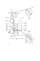
図1は、本発明に適用可能な布帛に対して記録を行うインクジェット記録方式の捺染機の画像プリント部の概要を示す模式図である。このプリント装置は、大きく分けて、捺染用の前処理を施されたロール状の布帛等のプリント媒体を送り出す給布部Bと、送られてきたプリント媒体を精密に行送りして、インクジェットヘッドでプリントを行う本体部Aと、プリントされたプリント媒体を乾燥させ巻取る巻取り部Cからなる。そして、本体部Aはさらにプラテンを含むプリント媒体の精密送り部A−1とインクジェットプリント部A−2とからなる。
【0044】
以下、プリント媒体として前処理されたプリント媒体を用い捺染を実施する場合を例にとってこの装置の動作を説明する。
【0045】
前処理されたロール状のプリント媒体236は給付部Bから送り出され、本体部に送られる。本体部には精密にステップ駆動される薄い無端のベルト237が駆動ローラ247、巻回ローラ249に架け回されている。駆動ローラ247は、高分解能のステッピングモータ(図示せず)でダイレクトにステップ駆動されてそのステップ量だけベルトをステップ送りする。送られてきた布236は巻回ローラ249によってバックアップされたベルト237表面に、押付けローラ240によって押付けられ、張付けられる。
【0046】
ベルトによってステップ送りをされてきたプリント媒体236は、第1のプリント部602において、ベルト裏面のプラテン232によって定位され表側からプリントされる。1行のプリントが終る毎に、所定量ステップ送りされ、次いでベルト裏面からの加熱プレート234による加熱と、温風ダクト235によって供給/排出される、表面からの温風によって乾燥される。続いて第2のプリント部603において、第1のプリント部と同様な方法で重ねプリントがなされる。
【0047】
プリントが終ったプリント媒体236は引き剥されて、前述の加熱プレート234と温風ダクト235と同様な後乾燥部246で再度乾燥され、ガイドロール241に導かれて巻取りロール248に巻取られる。そして、巻取られたプリント媒体236は本装置から取外され、バッチ処理で発色、洗浄、乾燥等の後処理工程を経て製品となる。
【0048】
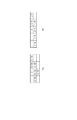
次に、インクジェットプリント部A−2付近の詳細について図2に基づき説明する。
【0049】
ここで、第1プリント部のヘッドにより、ドット数を間引いて情報をプリントし、乾燥工程を経て、第2プリント部のヘッドにより、第1プリント部で間引かれた情報を補完するようにインク滴を吐出する。
【0050】
図2において、プリント媒体236は、ベルト237に張り付けられて、図中の上方向にステップ送りされるようになっている。図中下方の第1プリント部602にはY,M,C,K用のインクジェットヘッド4本を搭載した第1のキャリッジ244がある。本例におけるインクジェットヘッド(プリントヘッド)は、インクを吐出するために利用されるエネルギーとして、インクに膜沸騰を生じさせる熱エネルギーを発生する素子を有するものを用いている。
【0051】
第1のプリント部の下流側にはベルトの裏面から加熱する加熱プレート234と、表側から乾燥させる温風ダクト235とからなる乾燥部245が設けられている。加熱プレート234の熱伝達面は、強くテンションをかけられた無端のベルト237に押し当てられ、中空になっている内側に通してある高温高圧の蒸気によって、ベルト237を裏面から強力に加熱する。ベルト237は貼り付けられているプリント媒体236を熱伝導によって直接に効果的に加熱する。加熱プレート面の内側は集熱のためのフィン234′が設けられていて熱を効率的にベルト裏面に集中できるようにしてある。ベルトに接しない側は断熱材243でカバーしてあり、放熱による損失を防いでいる。
【0052】
表側では、下流側の供給ダクト230から乾燥温風を吹き付けることによって、乾燥しつつあるプリント媒体236に、より湿度の低い空気を当てて効果を高めるようにしている。そしてプリント媒体236の搬送方向とは逆に流れて充分に水分を含んだ空気は、上流側の吸引ダクト233から、吹き付けの量よりもはるかに多量の吸引をすることによって、蒸発水分が漏れて周囲の機械装置に結露しないようにしてある。温風の供給源は図2の奥側にあり、吸引は手前側から行うようになっていて、プリント媒体236に対向している吹き出し口238と吸引口239との圧力差が長手方向全域にわたって均一になるようにしてある。空気の吹き付け/吸引部は裏面の加熱プレート234の中心に対して下流側にオフセットされており、充分に加熱された所に空気が当たるようにしてある。これらによって第1のプリント部602がプリント媒体236が受容した薄め液も含むインク中の多量の水分を強力に乾燥させる。
【0053】
その下流(図中、上方)には第2のプリント部603があり、第1のキャリッジと同様の構成の第2のキャッリジ244′で第2のプリント部を形成している。その下流には、温風ダクト235と同様の構成の後乾燥部46が設けられている。
【0054】
次に、インクジェット捺染プリントの具体例を説明する。先に説明したように図1は捺染に好適なインクジェットプリント装置の構成を示す図である。図1に示すようなインクジェットプリント装置を用いて、インクジェット印捺工程を経た後、プリント媒体を乾燥(自然乾燥を含む)させる。そして、引き続きプリント媒体繊維上の染料を拡散させ、かつ繊維への染料を反応定着させる工程を施す。この工程により、充分な発色性と染料の固着による堅牢性を得ることができる。
【0055】
この拡散、反応定着工程は従来公知の方法でよく、例えば、スチーミング法が挙げられる。なお、この場合、印捺工程の前に、予めプリント媒体にアルカリ処理を施してもよい。
【0056】
その後、後処理工程において、未反応の染料の除去及び前処理に用いた物質の除去が行われる。最後に、欠陥補正、アイロン仕上げ等の整理仕上げ工程を経てプリントが完成する。
【0057】
(実施例1)
本実施例では、従来例とは異なり2値化処理を行ってからフロントヘッドとリアヘッドへの2値データの振り分けを行うのではなく、2値化処理を行う前の多値のデータをフロントヘッド用とリアヘッド用に分配し、分配された多値データをそれぞれ異なる係数によりデータ変換し、変換されたデータに対しそれぞれ2値化処理を行っている。これにより、各走査における印字画像の「補完関係」を低減し、半バンドむらを防止することを可能にした。
【0058】
本実施例において、多値の画像データを2値化し、ヘッド駆動データに変換してノズルからインクを吐出させて印字するまでの処理内容を図10に示し、図を用いて処理の流れを説明する。
【0059】
(1) ホストコンピュータから転送された多値の画像データは画像データ記憶装置1001に記憶される。ここから1バンドごとにデータが読み出されていく。
【0060】
(2) パレット変換回路1002では画像データが各インク色の多値のデータに分解される。以下、黒インクBkについて代表して説明する。
【0061】
(3) γ変換回路1003−Kではそれぞれインク色に分解された多値のデータに対しγ変換が行なわれる。
【0062】
(4) ムラ補正回路1004−Kにてムラ補正テーブル(多値→多値のルックアップテーブル)によりノズルの特性ばらつきに起因したムラの補正を行う。
なおここまでは、図5に示す従来の処理と同じである。
【0063】
(5) 分配回路1005−K1,1005−K2でフロントヘッド用とリアヘッド用にデータの分配を行う。
【0064】
(6) データ変換回路1006−K1,1006−K2において、それぞれ分配されたデータを所定の係数でデータ変換を行う。
【0065】
(7) 低階調化回路1007−K1,1007−K2では、各ヘッド毎に誤差拡散法により低階調化処理が行われる。
【0066】
(8)TMC(Timing Memory Controller)回路1008−K1,1008−K2では各ヘッドごとに、1バンドのデータをノズル列方向に1列ずつ出力している。ヘッドのヘッド主走査方向の位置ズレを調整するのが横レジ調値であるが、横レジ調値に応じて1列分のデータの出力タイミングは異なる。
【0067】
(9)PHC(Printer Head間 コネクタ)基板1009−K1,1009−K2では、ノズル列方向の2値データを、実際に印字を行うノズルに対応させて出力する。ヘッドのノズル列方向の位置ズレを調整するのが縦レジ調値である。本例におけるヘッドは1344ノズルに加えて上下8ノズルが印字有効ノズルであるので、縦レジ調値は−8〜+8の範囲である。縦レジ調値が±0の場合は中央の1344ノズルを使用するが、縦レジ調値が±1〜8の場合は実際に印字する1344ノズルを中央から1〜8ノズル分ずらしている。この縦レジ調値によって、1344ノズル分のデータを実際に印字を行うノズルに対応させて出力する。
【0068】
(10) 最後に各ノズルの2値のデータを、印字制御装置(Head CPU)1010でヘッド駆動データに変換し、インクを吐出させて印字を行う。
【0069】
なお、本実施例では上述の処理を画像処理装置のハード構成にて実現した例を説明したが、適宜ソフトウエア等を用いて実現することも可能である。
【0070】
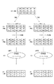
図11は図10の1005,1006,1007の処理の具体例を示したものである。図11において、多値のデータ(同図A)をフロントヘッド602に送るための画像データ(同図B)と、リアヘッド603に送るための画像データ(同図C)とに2つに分配する。分配されたデータにそれぞれ異なる係数を掛ける。例えば、注目画素のデータが100であった時、フロント用データとして100,リア用データとして100をそれぞれに分配する。次に、それぞれフロント用データを0.55倍(同図D)、リア用データを0.45倍(同図E)する。この時、各係数の和は後述のとおり、1とは限らない。また、ここでは、データの分配と変換を別々の回路で実現したが、1つの手段として実現してもよい。
【0071】
次に、データ変換されたそれぞれのデータを誤差拡散法により2値化し(同図F、G)、2値化されたデータ(同図H、I)をそれぞれのヘッドで印字する。
【0072】
図12は物理的な精度が理想的であると仮定した場合、ベタの画像を本発明による画像処理方法を用いて、フロントヘッドとリアヘッドで重ね印字を行った場合の図である。21(黒のドット)はフロントヘッドで印字したものを示し、22(白丸のドット)はリアヘッドで印字したものを示す。また、23(ハッチングのドット)はフロントヘッドとリアヘッドの両者で印字したものを示す。ベタの画像であるのにも係わらず印字されない画素や、フロントヘッドとリアヘッドの両者で印字されるドットが生じるのは、異なる係数をかけて得られた多値画像データを各々独立に2値化しているためであり、これが両者の補完関係を低減している根拠である。
【0073】
図13は図12において、フロントヘッドとリアヘッドのレジストレーションが微妙にずれている場合である。ここでは、フロントヘッドのレジストレーションが半ドット横にずれている場合を示す。図12と図13を比較しても、画像の濃度に大きな変化は見られない。つまり、各走査におけるレジストレーションが微妙に変化しても、濃度はほとんど変化せず、半バンドむらが生じないことがわかる。
【0074】
本実施例では、フロントヘッドのデータとリアヘッドの多値データに対して、異なる係数を掛けてそれぞれ2値化処理するために、それぞれのヘッドで印字する画像は「補完関係」が低減される。このため、レジストレーションの変化に対する依存度が低下するため、レジストレーションが微妙にずれた場合でも完全な補完関係にある場合に比べ画像濃度の変化が少なく、半バンドむらの軽減された画像を形成することができる。
【0075】
なお、ここでは本実施例によって複数のパスで形成される画像をマクロ的に捉えた「補完関係」の概念で説明したが、ミクロ的に捉えることも可能である。この場合、複数のパスで記録されるドットに着目し、あるパスで記録されたドットの隣に他のパスで記録されたドットが存在するという「相関関係」をなくした画像を形成する、と捉えることもできる。
【0076】
(実施例2)
図14は図10の1005,1006,1007の処理の部分の具体例を示したものである。図14において、多値のデータ(同図A0)をフロントヘッドに送るための画像データ(同図B)とリアヘッドに送るための画像データ(同図C)と2つに分配し、分配されたデータにそれぞれ同じ係数(0.5)を掛ける。データ変換されたそれぞれのデータ(同図D、E)を異なる誤差分配マトリックスの誤差拡散法(同図F、G)により2値化し、2値化したデータ(同図H,I)をそれぞれのヘッドで印字する。
【0077】
フロントヘッドとリアヘッド用に分配され、データ変換された多値データはそれぞれ同じであるが、誤差拡散の誤差分配マトリックスが互いに異なるため、それぞれのヘッドで印字する画像は「補完関係」が低減され、半バンドむらの軽減された画像を形成することが可能となる。
【0078】
(実施例3)
図15は図10の1005,1006,1007の処理の部分の具体例を示したものである。図15において、多値のデータ(同図A)をフロントヘッドに送るための画像データ(同図B)とリアヘッドに送るための画像データ(同図C)と2つに分配し、分配されたそれぞれの多値データに同じ係数)(0.5)を掛ける。データ変換された2つのデータ(同図D、E)をそれぞれしスレッショルド値の異なる誤差拡散法(同図F,G)により2値化し、2値化したデータ(同図H,I)をそれぞれのヘッドで印字する。
【0079】
フロントヘッドとリアヘッド用に分配され、変換された多値データはそれぞれ同じであるが、誤差拡散のスレッショルド値がそれぞれ異なるために、それぞれのヘッドで印字する画像は「補完関係」が低減され、半バンドむらの軽減された画像を形成するとが可能となる。
【0080】
実施例1〜実施例3のそれぞれの要素(フロントとリアのデータ変換係数,誤差拡散の誤差分配マトリックス,2値化のスレッショルド値)を組合わせても同様の効果を得ることができる。
【0081】
(実施例4)
図16は図10の1005,1006,1007の処理の部分の具体例を示したものである。図16において、多値のデータ(同図A)をフロントヘッドに送るための画像データ(同図B)とリアヘッドに送るための画像データ(同図C)と2つに分配し、分配されたデータにそれぞれ同じ係数(0.6)を掛ける。データ変換されたそれぞれのデータ(同図D、E)を異なる誤差分配マトリックスの誤差拡散法(同図F,G)により2値化し、2値化したデータをそれぞれのヘッドで印字する。ここで、実施例1〜3と異なるのは、データ変換処理における係数の和が1ではなく1以上であるという点である。本実施例4では、係数の和が1.2となっている。このことは即ち、100%以上のデューティーでの印字が可能であることを示している。
【0082】
本実施例4では、実施例2と同様に、データ変換されたそれぞれのデータを異なる誤差分配マトリックスの誤差拡散法により2値化し、2値化したデータをそれぞれのヘッドで印字するという処理のものを示したが、実施例1及び実施例3の処理においても、データ変換処理時のデータ変換係数の和が1以上になるものを用いることによって、100%以上のデューティーでの印字が可能となる。以下、実施例5、及び実施例6に関しても同様である。
【0083】
(実施例5)
次に、図10において、低階調化としてドット径変調を用いて4値化処理を行った場合の実施例について、図17に処理の具体例を示す。低階調化処理として4値化処理を行う以外は実施例1と同じで、多値のデータ(同図A)を同一領域を走査する回数分に分配し(同図B、C)、分配された多値データにそれぞれ異なる係数(0.55,0.45)を掛ける。それぞれ変換されたデータ(同図D,E)を誤差拡散法(同図F、G)により4値化し、4値化されたデータ(同図H,I)をそれぞれのヘッドで印字する。
【0084】
4値化処理を行っても、従来の処理方法で印字した場合、それぞれのヘッドで印字される画像には完全な「補完関係」があるが、本発明による処理を行うことで双方のヘッドの「補完関係」を低減し、半バンドむらを軽減した画像を形成することができる。
【0085】
実施例1〜3と同様に、誤差拡散法において誤差分配マトリックス,及びスレッショルド値を各走査にて異なるものを用いても、同様の効果を得ることができる。
【0086】
(実施例6)
次に、1色につき1本のヘッドを持つプリンタの実施例について図を用いて説明する。図10において、F(フロント)ヘッドを第1走査、R(リア)ヘッドを第2走査におき換えると、本実施例の画像処理の流れの図になる。
【0087】
図18は第1走査と第2走査の印字画像の重ね状態を示すものである。メディアの送り量は半バンドであり、第1走査と第2走査の半バンド重ねで画像を形成する。
【0088】
図19は、図10に対応させて処理の具体例を示したものである。図19において、実施例1〜実施例3と同様に、多値のデータ(同図A)を同一領域を走査する回数分(2つ)のデータ(同図B、C)に分配し、それぞれのデータを所定の係数(第1走査:0.55,第2走査:0.45)でデータ変換する(同図D,E)。変換されたデータを誤差拡散法(同図F,G)により2値化処理し、2値化したデータ(同図H,I)を第1走査と第2走査で印字する。
【0089】
メディアの副走査方向の送り量に誤差が生じたり、レジストレーションが微妙に変化しても、各走査で印字する画像は「補完関係」が低減されているので、半バンドむらの軽減された均一な画像を形成することができる。
【0090】
また、実施例1〜実施例3と同様に、誤差拡散法において、誤差分配マトリックス,及びスレッショルド値を各走査にて異なるものを用いても、同様の効果を得ることができる。
【0091】
(実施例7)
本実施例は、本発明をインクジェット方式の捺染機に適用した例を示すものであり、図20は本発明の実施例7を示すフルカラーインクジェット記録装置の概略構成を示す構造断面図である。
【0092】
図20において、100は被記録媒体としての布帛101(以下、被記録媒体ともいう)を搬送する搬送部、102は記録を行うプリンタユニット、103はプリントされた記録媒体101を巻き取る巻き取りユニット、104は記録媒体101を巻いた繰り出しローラ、105、106は押さえローラ、107は駆動ローラ、108、109はプリント部の平坦性を保つプラテン部、110は押さえローラ、111は駆動ローラ、112は乾燥部、113は巻き取りローラ、114はキャリッジユニット116を上に載せ支持する支柱、117はキャリッジユニットを主走査させるモータ、駆動ローラ107、111は搬送モータ115が駆動源である。搬送ベルト118は、キャリッジユニット116の走査領域を挟んで駆動ローラ107および111によって帳架され、接着剤が外側に塗布されており、これらローラが搬送モータ115によって駆動されることにより、被記録媒体101との間に生じる接着力および摩擦力が発生し、被記録媒体101を図中矢印A方向に搬送することができる。
【0093】
キャリッジユニット116は、キャリッジモータ117によって支柱114の上を水平に移動する。そして、キャリッジユニット116に設けられたインクジェットヘッド119〜134によるプリントが行われる。このうち119〜126は被記録媒体101の搬送路において上流側、つまり繰り出しローラ102に近い方に配置されるものであり、119はマゼンタインクを吐出する複数の吐出口を備えた(以下のヘッドについても同様)第1のマゼンタヘッド、120はイエローインクを吐出する第1のイエローヘッド、121はオレンジインクを吐出する第1のオレンジヘッド、122は淡マゼンタインクを吐出する第2の淡マゼンタヘッド、123はシアンインクを吐出する第1のシアンヘッド、124は淡シアンインクを吐出する第1の淡シアンヘッド、125はブルーインクを吐出する第1のブルーヘッド、126はブラックインクを吐出する第1のブラックヘッドである。
【0094】
また、インクジェットヘッド127〜134は被記録媒体101の搬送経路において下流側、つまり、インクジェットヘッド119〜126よりも後に記録される側に設けられるものであり、上流側のインクジェットヘッド119〜126の配置位置とは、これらヘッドによる走査がキャリッジユニット116による1回の走査で記録する幅(以下、バンド幅ともいう)の半分の距離だけずれた位置になるよう配置される。ここでは、0.5バンドずらして配置されている。これらのヘッドのうち、127はマゼンタインクを吐出する第2のマゼンタヘッド、128はイエローインクを吐出する第2のイエローヘッド、129はオレンジインクを吐出する第2のオレンジヘッド、130は淡マゼンタインクを吐出する第2の淡マゼンタヘッド、131はシアンインクを吐出する第2のシアンヘッド、132は淡シアンインクを吐出する第2の淡シアンヘッド、133はブルーインクを吐出する第2のブルーヘッド、134はブラックインクを吐出する第2のブラックヘッドである。
【0095】
従って、本実施形態では8色の異なるインクを吐出する8組の記録ヘッドが備えられ、各組2つづつの記録ヘッドは記録媒体101の搬送方向に0.5バンド幅だけ距離をおいて配置されている。なお、シアンとマゼンタの画像は、それぞれ(濃)シアンインクと淡シアンインク、(濃)マゼンタインクとマゼンタインクによって形成される。
【0096】
図21は、図20に示すインクジェットプリンタの制御構成を示すブロック図である。図21において、201はインクジェット捺染システムを制御するホストコンピュータを示す。
【0097】
ホストコンピュータ201からGPIB(General Purpose Interface Bus)インタフェースを介して転送されたプリント画像データは、CPU202の制御に従い一旦、フレームメモリ203に格納される。CPU203はホストコンピュータ201から発行されたプリント開始コマンドに従って、フレームメモリ203に格納されたプリント画像データから1主走査幅相当量を、多値/二値変換部204を介してシーケンシャルマルチスキャン部205へと順次読み出す。シーケンシャルマルチスキャン部205は、受けとったプリント画像データを第1バンドメモリ206、第2バンドメモリ207に振り分けて送出する。第1バンドメモリ206、第2バンドメモリ207内の画像データは、片方向印字あるいは双方向印字シーケンスに従って読み出され、それぞれ第1プリントヘッド208(図1のインクジェットヘッド119〜126に対応)、第2プリントヘッド209(図1のインクジェットヘッド127〜134に対応)によって記録される。なお、第2バンドメモリ207からは画像データを0.5バンド幅だけ遅延して第2プリントヘッド209に読み出すことにより、第1プリントヘッド206と第2プリントヘッド207の副走査方向における相対位置のずれを補正している。
【0098】
図22は、図20および図21に示すインクジェット捺染装置のプリンタユニット102による印刷処理を説明するための図である。
【0099】
ここで、第1バンドメモリ206に接続された第1プリントヘッド208は被記録媒体101の搬送方向Yの上流側に位置しており、被記録媒体101に対して最初の印刷を行う。
【0100】
この印刷に際しては、シーケンシヤル・マルチスキャンのアルゴリズムに従って振り分けられた第1バンドメモリ206の記録データに応じて記録(印刷)を行う。そして、第1プリントヘッド208の全ての吐出口を用い、往方向Xaの走査で記録媒体101に部分301aを記録する。
【0101】
記録された部分301aはプリントヘッドの吐出口配列幅Lに対応した所定量だけ搬送され、第2プリントヘッド209の記録領域に対応する領域301bとなる。この領域301bにマルチスキヤン方式に従って分配された残りの第2バンドメモリ207の記録データに基づいて、第2プリントヘッド209よって印刷が行われる。前述したように、第1プリントヘッド208と第2プリントヘッド209とは、その記録位置が互いに上記吐出口配列幅Lの半分だけずれている。このため、第2プリントヘッド209は、そのヘッドの吐出口の内、上流側半分の吐出口を用い、上記第1プリントヘッド208によりすでに記録された領域301bの下流側半分に相当する領域302Aに復方向Xbの走査で記録する。
【0102】
次に、記録媒体101が上記吐出口配列幅Lに相当する分だけ搬送され、記録媒体101の上記領域301bが、領域301cとなると、第2プリントヘッド209の下流側半分の吐出口を用いて、第1プリントヘッド208で記録された領域301cの上流側半分の領域301Bに往方向Xaの走査で記録する。以上のようにして第1プリントヘッド208および第2プリントヘッド209で記録された領域を符号302で表すことができる。
【0103】
以上説明したように、本実施例ではマルチスキヤン方式の採用により領域302のそれぞれのラインは第1プリントヘッド208と第2プリントヘッド209のそれぞれ異なる吐出口から吐出されるインクで形成されることになる。すなわち、第1および第2のプリントヘッド、208および209に対し記録データを2分して記録を行い、更に第1プリントヘッド208と第2プリントヘッド209とで記録する領域を、それぞれの吐出口のの上流側半分と下流側半分というようにそれぞれ異ならせているため、インクジェットヘッドの吐出口径や吐出方向等に起因する濃度ムラやすじ等を分散させることができる。
【0104】
図23は、図22に示したマルチスキャン方式に従って記録データを分配して供給するためのシーケンシャルマルチスキャン部205の内部回路の構成を示すブロック図である。ここでは、第1マゼンタヘッド119と第2マゼンタヘッド127に記録データを分配する場合を例にとって説明する。
【0105】
図23において、ランダム分配フラグ発生部401は、乱数発生用クロックφ2,φ3(φ1≠φ2≠φ3)から、記録データ転送同期クロックφ1に同期した第1分配フラグ(EN1)および第2分配フラグ(EN2)を発生する。これら分配フラグと記録データとの論理積演算の結果を、第1バンドメモリ206あるいは第2バンドメモリ207へ供給することにより、記録データの分配を行う。このとき、
(1)EN1=”H”,EN2=”L”のとき、
第1プリントヘッド208のみへ分配する。
(2)EN1=”L”,EN2=”H”のとき、
第2プリントヘッド209のみへ分配する。
(3)EN1=”H”,EN2=”H”のとき、
第1プリントヘッド208および第2プリントヘッド209の両方へ分配する。
(4)EN1=”L”,EN2=”L”のとき、
第1プリントヘッド208および第2プリントヘッド209共に分配しない(記録データ出力は共に”L”)。
【0106】
本実施例では分配条件(1)〜(4)に従ってランダムに出力される分配フラグに従って記録データ転送同期クロックφ1に同期しながら、記録データを合成部402がランダムに切り換えて出力する。ここで、合成部402は1ビット構成であるが、記録データは8ビット単位で転送されるために、図示しないバッファを入力(パラレル−シリアル変換)と出力(シリアル−パラレル変換)に備えている。
【0107】
図24はランダム分配フラグ発生部401の内部ブロック図である。
【0108】
本実施例では、互いに非同期なクロックφ2、φ3をそれぞれカウンタ501、502にて256種の値を発生する。これをAND−ORマトリクス503、504、505、506にて値の範囲を判定し、上記(1)、(2)、(3)および(4)の発生確率を決定する。上記AND−ORマトリクス503、504、505、506の詳細を示すブロック図とテーブルを図25に示す。
【0109】
本構成によれば、カウンタの値が、0〜63、128〜159、224〜231および254のとき、AND−ORマトリクス503において、第1バンドメモリ206のみへ画像データを送出することを示すフラグ信号Fを発生する。発生確率は約41%(105/256=41.015625%)になる。
【0110】
カウンタの値が、64〜127、160〜191、232〜239および255のとき、AND−ORマトリクス504において、第2バンドメモリ207のみへ画像データを送出することを示すフラグ信号Rを発生する。発生確率は約41%(105/256=41.015625%)になる。
【0111】
カウンタの値が、192〜223、240〜247、252および253のとき、AND−ORマトリクス505において、第1バンドメモリ206および第2バンドメモリ207へ画像データを送出することを示すフラグ信号Bを発生する。発生確率は約16.4%(42/256=16.40625%)になる。
【0112】
カウンタの値が、248〜251のとき、AND−ORマトリクス506において、第1バンドメモリ206および第2バンドメモリ207へ画像データを送出しないことを示すフラグ信号Bを発生する。発生確率は約1.6%(4/256=1.5625%)になる。
【0113】
本実施例ではAND−ORマトリクス503、504、505、506の構成を変更することで(1)、(2)、(3)および、(4)の発生確率をを約0.39%(0.390625%)刻みで設定することができる。
【0114】
先に示した図12は物理的な精度が理想的であると仮定した場合、ベタの画像を本発明による画像処理方法を用いて、第1プリントヘッドと第2プリントヘッドで重ね印字を行った場合の図と見ることも可能である。この場合、21(黒のドット)は第1プリントヘッドで印字したものを示し、22(白丸のドット)は第2プリントヘッドで印字したものを示す。また、23(ハッチングのドット)は第1プリントヘッドと第2プリントヘッドの両者で印字したものを示す。ベタの画像であるのにも係わらず印字されない画素や、第1プリントヘッドと第2プリントヘッドの両者で印字されるドットが生じるのは、上述の(1)、(2)の発生確率が0でないためであり、これにより両者の補完関係を低減している。
【0115】
先に示した図13は図12において、第1プリントヘッドと第2プリントヘッドのレジストレーションが微妙にずれている場合の図と見ることも可能である。この場合、第1プリントヘッドのレジストレーションが半ドット横にずれていることを示す。図12と図13を比較しても、画像の濃度に大きな変化は見られない。つまり、各走査におけるレジストレーションが微妙に変化しても、濃度はほとんど変化せず、半バンドむらが生じないことがわかる。
【0116】
本実施例では、従来と同様に、2値化した画像データを分配するものであるが、第1プリントヘッドと第2プリントヘッドに対して、ランダムに画像データを分配する際、ランダムに両方のヘッドに画像データを分配したり、ランダムにいずれのヘッドにも画像データを分配しないために、それぞれのヘッドで印字する画像は「補完関係」が低減される。このため、レジストレーションの変化に対する依存度が低下するため、レジストレーションが微妙にずれた場合でも完全な補完関係にある場合に比べ画像濃度の変化が少なく、半バンドむらの軽減された画像を形成することができる。
【0117】
以上のように、本実施例によれば、複数の記録ヘッド間の機械的な取付精度差による定量的なマルチスキャンで重ねられた単位記録画素間隔の差異を拡散することができ、結果的にモアレ効果や半走査間隔のムラを低減することができる。
【0118】
(実施例8)
図26は、図22に示したマルチスキャン方式に従って記録データを分配して供給するためのシーケンシャルマルチスキャン部205の内部回路の第2の構成を示すブロック図である。ここでは、第1マゼンタヘッド119と第2マゼンタヘッド127に記録データを分配する場合を例にとって説明する。
【0119】
図26において、図23に示したものと同じ構成要素には同じ参照番号を付し、これらの説明は省略する。図26の構成によれば、701は画像データ信号、702は画像データ信号に同期した1主走査中の画像データ有効期間信号、703は画像データ信号に同期したラスタラインでの画像データ有効期間信号、704はプリント開始時からの1主走査中の画像データ有効期間信号702をカウントし、カウント値が奇数か偶数かを判定する主走査方向判定部、705はラスタラインでの画像データ有効期間信号703をカウントし、画像データの吐出位置が記録ヘッドの上流側前半部か下流側後半部かを判定する吐出位置判定部である。
【0120】
図27は、図26におけるランダム分配フラグ発生部706の動作を説明するための図である。ここで、第1プリントヘッド208は往復主走査をおこなうことでプリント開始から往路プリント→復路プリント路→往路プリント→復路プリント・・・とプリント動作を繰り返す。また、第2プリントヘッド209においては、その取付位置が布搬送方向でバンド幅の1.5倍の間隔が開けられているとき、第1プリントヘッド208が2回目の往路プリント時に1回目の往路プリントを上流側前半部の吐出口でプリントし、その後、→復路プリント路→往路プリント→復路プリント・・・とプリント動作を繰り返す。従って、第1プリントヘッドと第2プリントヘッドの主走査方向に着目した重ね合せプリント条件は
第1プリントヘッド=往路 + 第2プリントヘッド=往路 ・・・81
第1プリントヘッド=往路 + 第2プリントヘッド=復路 ・・・82
第1プリントヘッド=復路 + 第2プリントヘッド=復路 ・・・83
第1プリントヘッド=復路 + 第2プリントヘッド=往路 ・・・84
の4種になり、これらがプリント開始時から
81→82→83→84→81→82→83・・・
と繰り返されることになる。
【0121】
図28はランダム分配フラグ発生部706の内部ブロック図である。
【0122】
本実施例では、第1プリントヘッドと第2プリントヘッドの主走査方向に着目した重ね合せプリント条件81〜84に対応する4種のAND−ORマトリクス群901、902、903、904を備え、プリント中に前記(1)〜(4)の分配条件の発生確率を切り換える。
【0123】
図29に4種のAND−ORマトリクス群901、902、903、904の設定例を示す。本設定例は記録ヘッドのプリント特性が
往路プリント時の濃度 < 復路プリント時の濃度
の時に有効な設定である。即ち、往路プリント時には記録ヘッドへの分配を相対的に高く設定することにより、往路と復路とでの濃度差を解消している。
【0124】
条件81(第1/第2:往路/往路)では、第1プリントヘッド208と第2プリントヘッド209へ共に分配する確率を約10%与え、プリント濃度を110%に高めることで、往路印字における濃度低下を防止している。
【0125】
条件82(第1/第2:往路/復路)では、第2プリントヘッド209へ分配する確率を減らすことで、プリント濃度を100%としながら第2プリントヘッド209による復路プリント頻度を約45%に減らしている。
【0126】
条件83(第1/第2:復路/復路)では、第1プリントヘッド208と第2プリントヘッド209へ共に分配しない確率を約10%与え、プリント濃度を90%にさげることで、復路印字における濃度上昇を防止している。
【0127】
条件84(第1/第2:復路/往路)では、第1プリントヘッド208へ分配する確率を減らすことで、プリント濃度を100%としながら第1プリントヘッド208による復路プリント頻度を約45%に減らしている。
【0128】
本実施例によれば、複数の記録ヘッド間の機械的な取付精度差による定量的なマルチスキャンで重ねられた単位記録画素間隔の差異を拡散することができ、結果的にモアレ効果や半走査間隔のムラを低減するすることは勿論、往路と復路でプリント特性が異なるプリントヘッドによる往復ムラを補正することができる。
【0129】
上述の実施形態7,8では、記録ヘッドが副走査方向にずれて配置された第1と第2のヘッドから構成され、両ヘッドによって記録媒体の所定領域への複数回の走査を行って画像を形成していた。本発明に適用可能な記録ヘッドは、これに限定されるものではなく、記録ヘッドの記録幅未満の紙送りを行うことによって、記録媒体の所定領域への複数回の走査を行うことも可能である。
【0130】
また、上述の実施形態7,8では、ランダム分配フラグ発生部によって画像データを複数(2つ)のバンドメモリに分配していたが、独立の乱数発生器を複数のバンドメモリに対応して設け、画像データをそれぞれの乱数発生器が発生した乱数に基づいて分配しても良い。独立の乱数によって分配されるので、両メモリに分配された画像データの補完関係が完全ではなくなるからである。
【0131】
要は、複数のメモリに画像データをランダムに分配する際、両メモリによって補完して形成される画像の補完関係が完全ではなく、低減されればよい。
【0132】
(実施例9)
実施例9の基本構成は、図20に示す実施例7の構成と同様である。
【0133】
図30は、本実施例のインクジェットプリンタの制御構成を示すブロック図である。図30において、2001はインクジェット捺染システムを制御するホストコンピュータを示す。
【0134】
ホストコンピュータ2001からGPIB(General PurposeInterface Bus)インタフェースを介して転送されたプリント画像データは、CPU2002の制御に従い、一旦、パレットデータ形式でフレームメモリ2003に格納される。CPU2002は、ホストコンピュータ2001から発行されたプリント開始コマンドに従って、フレームメモリ2003に格納されたプリント画像データから1主走査幅相当量を読み出す。読み出されたパレットデータはパレット変換部2004にて各インク色の発色特性に対応した多値階調画像データに変換される。変換された多値階調画像データは各色の記録ヘッドの基本吐出特性に対応したガンマ変換を行うガンマ補正部2005、各記録ヘッド固有の吐出特性を補正するムラ補正部2006にて処理がなされ、多値SMS部2007で第1記録ヘッド2014向けと第2記録ヘッド2015向けに分配される。
【0135】
2つに分配された多値階調画像データはそれぞれ第1データ変換部2008および第2データ変換部2009にて分配係数による変換処理がなされ、第1の2値化処理部2010および第2の2値化処理部2011にて誤差マトリクスと閾値を用いた誤差拡散法による2値化処理が行われる。2値化された2値画像データはそれぞれ第1バンドメモリ2012および第2バンドメモリ2013へ格納され、CPU2002が制御する片方向印字あるいは双方向印字シーケンスに従って読み出され、それぞれ第1プリントヘッド2014、第2プリントヘッド2015によって記録される。
【0136】
上記インクジェット捺染装置のプリンタユニットによる印刷処理は、先に説明した図22と同様である。
【0137】
図31は、マルチスキャン方式に従って多値階調画像データを分配して供給するための多値SMS部207の内部回路の構成を示すブロック図である。特に、第1マゼンタヘッド、第2マゼンタヘッドに記録データを分配する場合を例にとって説明する。
【0138】
図31において、ランダム分配フラグ発生部401は、乱数発生用クロックφ2,φ3(φ1≠φ2≠φ3)から、記録データ転送同期クロックφ1に同期した第1分配フラグ(EN1)および第2分配フラグ(EN2)を発生する。これら分配フラグと記録データとの論理積演算の結果を、第1データ変換部2008あるいは、第2データ変換部2009へ供給することにより、記録データの分配を行なう。このとき、
(1)EN1=“H”,EN2=“L”のとき、
第1データ変換部2008のみへ分配する。
(2)EN1=“L”,EN2=“H”のとき、
第2データ変換部2009のみへ分配する。
(3)EN1=“H”,EN2=“H”のとき、
第1データ変換部2008および第2データ変換部2009へ、等しく分配する。
(4)EN1=“L”,EN2=“L”のとき、
第1データ変換部2008および第2データ変換部2009、共に分配しない。(多値階調画像データ出力は共に“L”)
【0139】
本実施例では分配条件(1)〜(4)に従ってランダムに出力される分配フラグに従って、記録データ転送同期クロックφ1に同期しながら、記録データを合成部402がランダムに切り換えて出力する。図31中の合成部402は、1ビット構成で示してあり、マゼンタ色に関しては8個(8ビット)にて構成されている。図23との相違は、本実施例が1画素8ビットの多値データを分配するのに対して、図23では1画素1ビットの2値データを分配している点にある。
【0140】
なお、ランダム分配フラグ発生部401の内部ブロックは、図24と同様である。
【0141】
AND−ORマトリクス503、504、505、506の構成も図25と同様であり、(1)、(2)、(3)および、(4)の発生確率を約0.39%(0.390625%)刻みで設定することができる。第1データ変換部2008および第2データ変換部2009内のルックアップテーブル(LUT)にて各分配先の濃度に異なる変換係数をかけている。
【0142】
例えば、図32に示す処理の具体例では、不規則に分配される多値階調画像データの注目画素の多値階調値に、第1データ変換部2008にて第1プリントヘッド2014向けデータ変換係数として「F1=1.10」を、第2データ変換部2009にて第2プリントヘッド2015向けデータ変換係数として「F2=0.90」を乗じている。ただし、このときの各係数の和は「2」には限らない。この和を調整することで画像の濃度を調整することができる。これらの演算は画像データ転送速度と等しく同期しながら行われ、それぞれ第1の2値化処理部2011、第2の2値化処理部2012へと送出される。
【0143】
本実施例では、複数の定量的なマルチスキャンで重ねられる多値階調画像データそれぞれを画素単位に不規則に分配し、「補完関係」を低減している。つまり互いに非補完の関係にしている。従って、複数の記録ヘッド間の機械的な取付精度差による単位記録画素間隔の差異を拡散することができ、結果的にモアレ効果や半走査間隔のムラを低減することができる。
【0144】
(実施例10)
図33は実施例10における、特に、多値SMS処理部2007および、第1データ変換部2008(または第2データ変換部2009)のブロック図を示したものである。ここでは、図30に示したものと同じ構成要素には同じ参照番号を付し、これらの説明は省略する。
【0145】
多値SMS処理部2007では、第1プリントヘッド2014向けと第2プリントヘッド2015向けに等しく多値階調画像データを分配している。
【0146】
第1データ変換部2008および第2データ変換部2009はそれぞれ異なる値が設定されたルックアップテーブル(LUT)2801および2802で構成され、分配された多値階調画像データに、それぞれ異なる係数を乗ずる。
【0147】
第1の2値化処理部2010および第2の2値化処理部2011では、データ変換された各々の画像データに、異なる構造の誤差拡散マトリクスA(2803)および誤差拡散マトリクスB(2804)による周辺画素への分散と、異なる閾値Th1(2805)およびTh2(2806)を用いた誤差拡散法による2値化演算を行う。
【0148】
例えば、図34に示す処理の具体例では、8ビット構造を備えた注目画素の多値階調値が、例えば「80」に、第1データ変換部2008にて第1ヘッド向けデータ変換係数として「F1=0.55」(2801)を、第2データ変換部2009にて第2ヘッド向けデータ変換係数として「F2=0.45」(2802)を乗じている。このとき、各係数の和は「1」には限らない。これらの演算は画像データ転送速度と等しく同期しながら行われ、それぞれ第1の2値化処理部2010、第2の2値化処理部2011へと送出される。
【0149】
第1の2値化処理部2010では、誤差拡散マトリクスA(2803)によって、注目画素値の5/32または9/32の値を、図示の注目画素(*)の周囲に加算し、第2の2値化処理部2011では、誤差拡散マトリクスB(2804)によって、注目画素値の1/8または2/8の値を、図示の注目画素の周囲に加算することで、複数画素への拡散を行う。その後、第1の2値化処理部2010では、閾値として「Th1=135」、第2の2値化処理部2011では閾値として「Th2=175」を用いた2値化処理が画像転送速度に同期して実行される。
【0150】
本実施例によれば、複数の定量的なマルチスキャンで重ねられる多値階調画像データを等しく分配するため、データ分配直後の画像データには相関関係がある。しかし、分配後のデータ変換係数、誤差拡散マトリクスの構造、2値化閾値がそれぞれ異なることから、マルチスキャンによる補完関係が大きく低減されることで、定量的な差異を拡散することができ、結果的に半走査間隔のムラを低減することができる。
【0151】
(実施例11)
図35は実施例11における、多値SMS部2007の内部で、特に、第1マゼンタヘッド119、第2マゼンタヘッド127に記録データを分配する回路の構成を示すブロック図である。ここでは、図30に示したものと同じ構成要素には同じ参照番号を付し、これらの説明は省略する。
【0152】
図35において、多値階調画像データは1ビット下位にシフトして約1/2の値となり第1の+1加算器1001および第2の+1加算器1002へ入力される。ビットシフトはフリップフロップ1000の出力を第1、第2の加算器1001、1002に入力する際にシフトすることでなされる。また、1ビット下位シフトにより溢れた最下位ビットb0は、画像データ転送同期クロックφ1に同期して、第1の+1加算器1001および第2の+1加算器1002の他方の1ビット入力として画素単位で交互に与えられる。これにより、第1、第2の加算器1001、1002からは画像データを1/2した余りが交互に加算されて出力される。
【0153】
図36は実施例11に関わる、多値SMS処理部2007および第1データ変換部2008および第1の2値化処理部2010(または第2データ変換部2009および第2の2値化処理部2011)の処理の具体例を示したものである。ここでは、図30に示したものと同じ構成要素には同じ参照番号を付し、これらの説明は省略する。
【0154】
多値階調画像データは多値SMS処理部2007にて第1プリントヘッド2014向けと第2プリントヘッド2015向けに、ほぼ2分されて分配され、第1データ変換部2008および第2データ変換部2009へ送出される。第1データ変換部2008および第2データ変換部2009はそれぞれ異なる値が設定されたルックアップテーブル(LUT)2801および2802で構成され、分配された多値階調画像データに、異なる係数を乗ずる。この時、第1データ変換部2008および第2データ変換部2009内のルックアップテーブル(LUT)2801および2802にて各分配先の濃度を変換する。
【0155】
第1の2値化処理部2010および第2の2値化処理部2011では、データ変換されたそれぞれの画像データに、異なる構造を備えた誤差分配マトリクス、および異なる閾値を用いた誤差拡散法による2値化演算を行う。
【0156】
図37に示す処理の具体例では、ほぼ1/2に分配される多値階調画像データの注目画素の多値階調値、例えば「80」に、第1データ変換部2008にて第1プリントヘッド2014向けデータ変換係数として「F1=1.15」(2801)を、第2データ変換部2009にて第2プリントヘッド2015向けデータ変換係数として「F2=0.85」(2802)を乗じている。ただし、このときの各係数の和は「2」には限らない。これらの演算は画像データ転送速度と等しく同期しながら行われ、それぞれ第1の2値化処理部2010、第2の2値化処理部2011へと送出される。
【0157】
第1の2値化処理部2010では、誤差拡散マトリクスA(2803)によって、注目画素値の5/32または9/32の値を、図示の注目画素(*)の周囲に加算し、第2の2値化処理部2011では、誤差拡散マトリクスB(2804)によって、注目画素値の1/8または2/8の値を、図示の注目画素の周囲に加算することで、複数画素への拡散を行う。その後、第1の2値化処理部2010では、閾値として「Th1=135」、第2の2値化処理部2011では閾値として「Th2=175」を用いた2値化処理が画像転送速度に同期して実行される。
【0158】
本実施例によれば、複数の定量的なマルチスキャンで重ねられる多値階調画像データはほぼ1/2に分配され、データ分配直後の画像データには、ほぼ相関関係がある。しかし、分配後のデータ変換係数、誤差拡散マトリクスの構造、2値化閾値がそれぞれ異なることから、マルチスキャンによる補完関係が大きく低減されることで、定量的な差異を拡散することができ、結果的に半走査間隔のムラを低減することができる。なお、本実施例では第1、第2データ変換部と第1、第2の2値化処理部の構成を異ならせているが、2値化処理部に誤差拡散法を用いているので、必ずしも異ならせる必要はない。分配された画像データに相関関係があっても、2値化の際に相関関係が低減されるからである。
【0159】
(実施例12)
図38は実施例12における、多値SMS部2007の内部で、特に第1マゼンタヘッド119、第2マゼンタヘッド127に記録データを分配する回路の構成を示すブロック図である。ここでは、図30に示したものと同じ構成要素には同じ参照番号を付し、これらの説明は省略する。
【0160】
図38において、交互分配フラグ発生部1301は、画像データ転送同期クロックφ1に同期した第1分配フラグ(EN1)および第2分配フラグ(EN2)を交互に発生する。これら交互分配フラグと記録データとは、合成部402にて論理積が演算され、第1データ変換部2008あるいは、第2データ変換部2009へ交互に分配される。
【0161】
図39は実施例12に関わる、多値SMS処理部2007および第1データ変換部2008および第1の2値化処理部2010(または第2データ変換部2009および第2の2値化処理部2011)の処理の具体例を示したものである。ここでは、図30に示したものと同じ構成要素には同じ参照番号を付し、これらの説明は省略する。
【0162】
多値階調画像データは多値SMS処理部2007にて第1プリントヘッド2014向けと第2プリントヘッド2015向けに、画素単位に交互に分配され、第1データ変換部2008および第2データ変換部2009へ送出される。第1データ変換部2008および第2データ変換部2009はそれぞれ異なる値が設定されたルックアップテーブル(LUT)2801および2082で構成され、分配された多値階調画像データに異なる係数を乗ずる。
【0163】
第1の2値化処理部2010および第2の2値化処理部2011では、データ変換されたそれぞれの画像データに、異なる構造を備えた誤差分配マトリクス、および異なる閾値を用いた誤差拡散法による2値化演算を行う。
【0164】
図40は第1データ変換部2008および第1の2値化処理部2010(または第2データ変換部2009および第2の2値化処理部2011)の処理の具体例を示したものである。ここでは、図30に示したものと同じ構成要素には同じ参照番号を付し、これらの説明は省略する。
【0165】
例えば、図40に示す処理の具体例では、8ビット構造を備えた注目画素の多値階調値、例えば「80」に、第1データ変換部2008にて第1ヘッド向けデータ変換係数として「F1=1.20」(2801)を、第2データ変換部2009にて第2ヘッド向けデータ変換係数として「F2=0.80」(2802)を乗じている。このとき、各係数の和は「2」には限らない。これらの演算は画像データ転送速度と等しく同期しながら行われ、それぞれ第1の2値化処理部2010、第2の2値化処理部2011へと送出される。
【0166】
第1の2値化処理部2010では、誤差拡散マトリクスA(2803)によって、注目画素値の5/32または9/32の値を、図示の注目画素(*)の周囲に加算し、第2の2値化処理部2011では、誤差拡散マトリクスB(2804)によって、注目画素値の1/8または2/8の値を、図示の注目画素の周囲に加算することで、複数画素への拡散を行う。その後、第1の2値化処理部2010では、閾値として「Th1=140」、第2の2値化処理部2011では閾値として「Th2=180」を用いた2値化処理が画像転送速度に同期して実行される。
【0167】
本実施例によれば、複数の定量的なマルチスキャンで重ねられる多値階調画像データが画素単位で交互に分配され、データ分配直後の画像データには相関関係がある。しかし、分配後の誤差拡散マトリクスの閾値が異なり、さらに、交互分配により演算結果の差が顕著化することから、マルチスキャンによる補完関係が低減されることで、定量的な差異を拡散することができ、結果的に半走査間隔のムラを低減することができる。
【0168】
また、実施例9から実施例12の構成を適宜組み合わせることで、ムラを低減する効果を高めることができる。
【0169】
次に、上記構成の記録装置によって実行される捺染記録の工程全体を説明する。上述のインクジェット方式に従う記録装置を用いて、インクジェット印捺工程を経た後、布帛を乾燥(自然乾燥を含む)させる。そして、引き続き布帛繊維上の染料を拡散させ、且つ布帛への染料を反応定着させる工程を施す。この工程により、十分な発色性と染料の固着による堅牢性を得ることができる。
【0170】
この拡散、反応定着工程は従来公知の方法でよく、例えば、スチーミング法が挙げられる。尚、この場合、印捺工程の前に、予め布帛にアルカリ処理を施しても良い。
【0171】
その後、後処理工程において、未反応の染料の除去および前処理に用いた物質の除去が行われる。最後に、欠陥補正、アイロン仕上げなどの整理し挙げ工程を経て記録が完成する。
【0172】
特にインクジェット捺染用布帛としては、
(1)インクを十分な濃度に発色させ得ること。
(2)インクの染着率が高いこと。
(3)インクが布帛上で速やかに乾燥すること。
(4)布帛上での不規則なインク滲みの発生が少ないこと。
(5)装置内での搬送性に優れること。
等の性能が要求される。これらの要求性能を満足させるために、本発明において、不要に応じて布帛に対し、予め前処理を施しておくことができる。例えば、特開昭62−53492号公報においてはインク受容量を有する布帛類が開示され、特開平3−46589号公報においては還元防止剤やアルカリ性物質を含有させた布帛の提案がなされている。このような前処理の例としては、布帛にアルカリ性物質、水溶性高分子、合成高分子、水溶性金属塩、尿素およびチオ尿素から選ばれる物質を含有させる処理を挙げることができる。
【0173】
アルカリ性物質としては、例えば、水酸化ナトリウム、水酸化カリウムなどの水酸化アルカリ金属、モノ、ジ、トリエタノールアミン等のアミン類、炭酸ナトリウム、炭酸カリウム、重炭酸ナトリウム等の炭酸もしくは重炭酸アルカリ金属塩などが挙げられる。さらに酢酸カルシウム、酢酸バリウム等の有機酸金属塩やアンモニアおよびアンモニア化合物等がある。また、スチーミングおよび」乾熱下でアルカリ物質となるトリクロロ酢酸ナトリウム等も用い得る。特に好ましいアルカリ性物質としては、反応性染料の染色に用いられる炭酸ナトリウムおよび重炭酸ナトリウムがある。
【0174】
水溶性高分子としては、トウモロコシ、小麦などのデンプン物質、カルボキシメチルセルロース、メチルセルロース、ヒドロキシエチルセルロース等のセルロース系物質、アルギン酸ナトリウム、アラビアゴム、ローカスイトビーンガム、トラガントガム、グアガム、クマリンド種等の他糖類、ゼラチン、カゼイン等の蛋白質物質、タンニン系物質、リグニン系物質等の天然水溶性高分子が挙げられる。
【0175】
また、合成高分子としては、例えば、ポリビニルアルコール系化合物、ポリエチレンオキサイド系化合物、アクリル酸系水溶性高分子、無水マレイン酸系水溶性高分子などが挙げられる。これらの中でも他糖類系高分子やセルロース系高分子が好ましい。
【0176】
水溶性金属塩としては、例えば、アルカリ金属、アルカリ土類金属のハロゲン化物のように、典型的なイオン結晶を作るものであって、ph4〜10である化合物が挙げられる。かかる化合物の代表的な例としては、例えば、アルカリ金属では、NaCl、Na2SO4、KClおよびCH3COONa等が挙げられ、また、アルカリ土類金属としては、CaCl2およびMgCl2などが挙げられる。
中でも、Na、KおよびCaの塩類が望ましい。
【0177】
前処理において上記物質などを布帛に含有させる方法は特に制限されないが、通常行われる浸漬法、パッド法、コーティング法、スプレー法などを挙げることができる。さらに、インクジェット捺染用布帛に付与される捺染インクは、布帛上に付与された状態では単に付着しているに過ぎないので、引き続き繊維への捺染等インク中の色素の定着工程を施すのが望ましい。このような定着工程は、従来公知の方法でよく、例えば、スチーミング法、HTスチーミング法、サーモフィックス法、あらかじめアルカリ処理した布帛を使用しない場合は、アルカリパッドスチーム法、アルカリブロッチスチーム法、アルカリショック法、アルカリコールドフィックス法等が挙げられる。また、定着工程は、染料によって反応工程を含むものと、含まないものとがあり、後者の例としては繊維に含浸させて物理的に離脱しないものもある。また、インクとしては所要の色素を有するものであれば適宜のものを用いることができ、染料に限らず顔料を含むものでもよい。
【0178】
さらに、未反応の染料の除去および前処理に用いた物質の除去は、上記反応定着工程の後に従来公知の方法に準じ、洗浄により行うことができる。なお、この洗浄の際に従来のフィックス処理を併用することが好ましい。
【0179】
以上述べた後処理工程が施されたプリント物は、その後、所望の大きさに切り離され、切り離された片は、逢着、接着、溶着など、最終的な加工品を得るための工程が施され、ワンピース、ドレス、ネクタイ、水着などの衣類や布団カバー、ソファカバー、ハンカチ、カーテンなどが得られる。布帛を縫製などにより加工して衣類やその他の日用品とする方法は、従来より公知の技術である。
【0180】
尚、プリント用媒体としては、布帛、壁布、刺繍に用いられる糸、壁紙、紙、OHPフィルム、アルマイトなどの板状物、その他、インクジェット技術を用いて所定の液体を付与可能な種々の媒体が挙げられ、布帛としては、素材、織り方、編み方を問わず、あらゆる織物、不織物およびその他の布地を含む。
【0181】
本発明は、上述したインクジェット記録方式に限らず種々の記録方式を採用できるが、インクジェット方式を採用する場合には、その中でも、インク吐出を行わせるために利用されるエネルギーとして熱エネルギーを発生する手段を備え、その熱エネルギーによりインクの状態変化を生起させる方法、すなわちキヤノン株式会社が提唱するバブルジェット方式の記録ヘッド、記録装置を用いることで優れた効果をもたらすものである。かかる方式によれば記録の高密度化、高精細化が達成できるからである。
【0182】
その他、代表的な構成や原理については、例えば、米国特許第4723129号明細書、同第4740796同明細書に開示されている基本的な原理を用いて行うものが望ましい。この方法は所謂オンデマンド型、コンティニュアス型のいずれにも適用可能であるが、特に、オンデマンド型の場合には、液体(インク)が保持されているシートや液路に対応して配置されている電気熱変換体に、記録情報に対応していて核沸騰を超える急速な温度上昇を与える少なくとも1つの駆動信号を印加することによって、電気熱変換体に熱エネルギーを発生せしめ、記録ヘッドの熱作用綿に膜沸騰を生じさせて、結果的に、この気泡の成長、収縮により吐出用開口部を介して液体(インク)を吐出させて、少なくとも1つの滴を形成する。この駆動信号をパルス形状とすると、即時適切に気泡の成長収縮が行われるので、特に応答性に優れた液体(インク)の吐出が達成でき、より好ましい。このパルス形状の駆動信号としては、米国特許第4463359号明細書、同第4345262同明細書に記載されているようなものが適している。なお、上記熱作用面の温度上昇率に関する発明の米国特許第4313124号明細書に記載されている条件を採用すると、さらに優れた記録を行うことができる。
【0183】
記録ヘッドの構成としては、上述の明細書に開示されているような吐出口、液路、電気熱変換体の組み合わせ構成(直線状液流路)の他に熱作用部が屈曲する領域に配置されている構成を開示する米国特許第4558333号明細書、米国特許第4459600号明細書を用いた構成も本発明に含まれるものである。加えて、複数の電気熱変換体に対して、共通するスリットを電気熱変換体の吐出部とする構成を開示する特開昭59−123670号公報や熱エネルギーの圧力波を吸収する開口を吐出部に対応させる構成を開示する特開昭59−138461号公報に基づいた構成としても本発明の効果は有効である。すなわち、記録ヘッドの形態がどのようなものであっても、本発明によれば記録を確実に効率よく行うことができるようになるからである。
【0184】
加えて、記録ヘッドは、記録装置の形態に対応して構成できるのは勿論であり、所謂ラインプリンタ形態のものに対しては記録媒体の幅に対応した範囲にわたって吐出口を配列したものとすればよい。また、上例のようなシリアルタイプの記録ヘッドとしては、装置本体に固定された記録ヘッド、あるいは装置本体に装着されることで装置本体との電気的な接続や装置本体からのインクの供給が可能になる交換自在のチップタイプの記録ヘッド、あるいは、記録ヘッド自体に一時的にインクタンクが設けられたカートリッジタイプの記録ヘッドを用いた場合にも本発明は有効である。
【0185】
また、本発明の記録装置の構成として、記録ヘッドの吐出回復手段、予備的な吐出補助手段を付加することは記録動作を一層安定することができるので好ましいものである。これらを具体的に挙げれば、記録ヘッドに対してのキャッピング手段、クリーニング手段、加圧あるいは吸引手段、電気熱変換体あるいはこれとは別の加熱素子あるいはこれらの組み合わせを用いて加熱を行う予備加熱手段、記録とは別の吐出を行う予備吐出手段を挙げることができる。
【0186】
さらに加えて、以上述べた本実施例に於いては、インクを液体として説明しているが、室温やそれ以下で固化するインクであって、室温でも軟化もしくは液化するものを用いてもよく、或いはインクジェット方式ではインク自体を30℃以上70℃以下の範囲内で温度調整を行ってインクの粘性を安定吐出範囲にあるように温度制御するものが一般的であるから、記録信号付与時にインクが液状をなすものを用いてもよい。加えて、熱エネルギーによる昇温を、インクの固形形態から液状形態への状態変化のエネルギーとして使用せしめることで積極的に防止するため、またはインクの蒸発を防止するため、放置状態で固化し加熱によって液化するインクを用いてもよい。いずれにしても熱エネルギーの記録信号に応じた付与によって液体が液化し、液状インクが吐出されるものや記録媒体に到達する時短では既に固化し始めるものなどのような、熱エネルギーの付与によって初めて液化する性質のインクを使用する場合にも本発明は適用可能である。このような場合のインクは、特開昭54−56847号公報あるいは特開昭60−71260号公報に記載されるような、多孔質シート凹部または貫通孔に液体または固形物として保持された状態で、電気熱変換体に対して対向するような形態としてもよい。本発明に於いては、上述した各インクに対して最も有効なのは、上述した膜沸騰方式を実行するものである。
【0187】
さらに加えて、本発明の形態としては、コンピュータなどの情報処理機器の画像出力端末として用いられているものの他、リーダなどと組み合わせた複写装置の形態を探るものなどであってもよい。
【0188】
なお、本発明は、複数の機器(例えばホストコンピュータ、インタフェース機器、リーダ、プリンタなど)から構成されるシステムに適用しても、一つの機器からなる装置(例えば、複写機、ファクシミリ装置など)に適用してもよい。
【0189】
また、本発明の目的は、前述した実施形態の機能を実現するソフトウェアのプログラムコードを記録した記憶媒体を、システム或いは装置に供給し、そのシステム或いは装置のコンピュータ(またはCPUやMPU)が記録媒体に格納されたプログラムコードを読み出し実行することによっても、達成されることは言うまでもない。
【0190】
この場合、記憶媒体から読み出されたプログラムコード自体が前述した実施形態の機能を実現することになり、そのプログラムコードを記憶した記憶媒体は本発明を構成することになる。
【0191】
プログラムコードを供給するため記憶媒体としては、例えば、フロッピィディスク、ハードディスク、光ディスク、光磁気ディスク、CD−ROM、CD−R、磁気テープ、不揮発性のメモリカード、ROMなどを用いることができる。
【0192】
また、コンピュータが読み出したプログラムコードを実行することにより、前述した実施形態の機能が実現されるだけでなく、そのプログラムコードの指示に基づき、コンピュータ上で稼働しているOS(オペレーティングシステム)などが実際の処理の一部または全部を行い、その処理によって前述した実施形態の機能が実現される場合も含まれることは言うまでもない。
【0193】
さらに、記憶媒体から読み出されたプログラムコードが、コンピュータに挿入された機能拡張ボードやコンピュータに接続された機能拡張ユニットに備わるメモリに書き込まれた後、そのプログラムコードの指示に基づき、その機能拡張ボードや機能拡張ユニットに備わるCPUなどが実際の処理の一部または全部を行い、その処理によって前述した実施形態の機能が実現される場合も含まれていることは言うまでもない。
【0194】
【発明の効果】
本発明によれば、物理的な精度誤差によるレジストレーションが微妙に変化しても、レジストレーションの変化に対する依存度が低下するため、画像濃度が大きく変化せず濃度むらの軽減された均一な画像を形成することができる。
【0195】
また、往復主走査を伴う記録動作においては、記録方向の違いによって発生する濃度ムラをも低減することができる。これによって、例えば、綿、絹、ナイロン、ポリエステルなどの記録媒体への捺染記録の生産性を向上させることができる。
【図面の簡単な説明】
【図1】本発明に適用可能な布帛に対して記録を行うインクジェット記録方式の捺染機の画像プリント部の概要を示す模式図である。
【図2】図1に示すインクジェットプリント部A−2付近の詳細を示す斜視図である。
【図3】本発明に適用可能なヘッドの並び状態を示す図である。
【図4】フロントヘッドとリアヘッドの印字画像の重ね状態を示す図である。
【図5】従来のプリンタに送られたデータが印字されるまでに処理される流れを示すブロック図である。
【図6】誤差の分配マトリックスの例を示した図である。
【図7】従来の画像処理方法の流れを示す図である。
【図8】従来の理想的なフロントヘッドとリアヘッドで重ね印字を行った場合のドットの配置を示す図である。
【図9】従来の実際のフロントヘッドとリアヘッドで重ね印字を行った場合のドットの配置を示す図である。
【図10】本発明におけるプリンタに送られたデータが印字されるまでの処理の流れを示すブロック図である。
【図11】本発明の実施例1における画像処理の具体例を示す図である。
【図12】本発明により理想的なフロントヘッドとリアヘッドで重ね印字を行った場合のドットの配置を示す図である。
【図13】本発明により実際のフロントヘッドとリアヘッドで重ね印字を行った場合のドットの配置を示す図である。
【図14】本発明の実施例2における画像処理の具体例を示す図である。
【図15】本発明の実施例3における画像処理の具体例を示す図である。
【図16】本発明の実施例4における画像処理の具体例を示す図である。
【図17】本発明の実施例5における画像処理の具体例を示す図である。
【図18】本発明適用可能な一色あたり一本のヘッドを持つプリンタの各走査の印字画像の重ね状態を示す図である。
【図19】本発明の実施例6における画像処理の具体例を示す図である。
【図20】本発明の実施例7であるフルカラーインクジェット捺染装置の概略構成を示す断面図である。
【図21】本発明の実施例7における画像データ処理の流れを示すブロック図である。
【図22】本発明の実施例7によるシーケンシャル・マルチスキャンによる記録方法示す説明図である。
【図23】本発明の実施例7におけるシーケンシャルマルチスキャン実行部の構成を示すブロック図である。
【図24】本発明の実施例7におけるランダム分配フラグ発生部の構成を示すブロック図である。
【図25】本発明の実施例7におけるAND−ORマトリクス部の構成を示すブロック図である。
【図26】本発明の実施例8におけるシーケンシャルマルチスキャン実行部の構成を示すブロック図である。
【図27】本発明の実施例8によるシーケンシャル・マルチスキャンによる記録方法示す説明図である。
【図28】本発明の実施例8におけるランダム分配フラグ発生部の構成を示すブロック図である。
【図29】本発明の実施例8におけるAND−ORマトリクス部の動作を説明するための図である。
【図30】本発明の実施例9であるフルカラーインクジェット捺染装置における画像データ処理の流れを示すブロック図である。
【図31】本発明の実施例9における多値SMS実行部の構成を示すブロック図である。
【図32】本発明の実施例9における多値SMS実行部、データ変換部の具体的な動作を示す図である。
【図33】本発明の実施例10における多値SMS実行部、データ変換部および2値化処理部の構成を示すブロック図である。
【図34】本発明の実施例10による多値SMS実行部とデータ変換部の具体的な動作を示す図である。
【図35】本発明の実施例11における多値SMS実行部の構成を示すブロック図である。
【図36】本発明の実施例11における多値SMS実行部、データ変換部および2値化処理部の構成を示すブロック図である。
【図37】本発明の実施例11における多値SMS実行部、データ変換部および2値化処理部の具体的な動作を示す図である。
【図38】本発明の実施例12における多値SMS実行部の構成を示すブロック図である。
【図39】本発明の実施例12における多値SMS実行部、データ変換部および2値化処理部の構成を示すブロック図である。
【図40】本発明の実施例12における多値SMS実行部、データ変換部および2値化処理部の具体的な動作を示す図である。
【符号の説明】
201 ホストコンピュータ
202 CPU
203 フレームメモリ
204 多値/二値変換部
205 シーケンシャルマルチスキャン部
206 第1バンドメモリ
207 第2バンドメモリ
208 第1プリントヘッド
209 第2プリントヘッド
212 第2プリントヘッド
1001 画像データ記憶装置
1002 パレット変換回路
1003 γ変換回路
1004 ムラ補正回路
1005 分配回路
1006 データ変換回路
1007 低階調化回路
1008 TMC(Timing Memory Controller)回路
1009 PHC(Printer Head間Connector)基板
1010 印字制御装置
601 記録ヘッド部
602 フロントヘッド
603 リアヘッド[0001]
BACKGROUND OF THE INVENTION
The present invention relates to an image forming apparatus, an image forming method, and an image processing method that perform recording on a recording medium while reducing density unevenness due to variations in recording characteristics among a plurality of recording elements in a recording head. In particular, the present invention relates to an image forming apparatus, an image forming method, and an image processing method for performing recording on a recording medium by reducing moire caused by errors in the mounting positions of a plurality of recording heads.
[0002]
[Prior art]
As an example of an apparatus using a recording head provided with a plurality of recording elements, an ink jet recording apparatus using a recording head provided with a plurality of ink discharge ports has been known.
[0003]
In such an apparatus, the size and position of the dots formed by the ink may vary due to variations in the discharge port diameter and the discharge direction of the discharge ports, and density unevenness may occur in the printed image. In particular, in a serial type recording apparatus that performs recording by scanning the recording head in a direction different from the arrangement direction of the plurality of recording elements, e.g., a direction orthogonal to the recording head, the density unevenness due to the above-described variation in the discharge port diameter is Since it appears in the printed image as stripes, the quality of the printed image may be further reduced.
[0004]
In order to correct such density unevenness, when image formation is performed using a recording head according to an ink jet recording method, image data subjected to gradation reduction processing (binarization processing, etc.) is transferred to a plurality of different ejection openings. A method has been proposed in which an image of a pixel composed of one pixel or a line corresponding to one scan of the recording head is formed with ink ejected from the printer. This can be realized, for example, by supplementing one pixel with a plurality of scans (scans, passes) by feeding paper less than the width of the recording head.
[0005]
FIG. 3 is a view showing a state of arrangement of conventional ink jet recording head portions. This printer constitutes an image with four basic colors of CMYK inks. The
[0006]
FIG. 4 is a diagram illustrating a print overlapping state of the
[0007]
FIG. 5 shows the processing contents from binarizing the multi-valued image data transferred to the printer, converting it into head drive data, ejecting ink from the nozzles, and printing. explain.
[0008]
(1) Multi-value image data transferred from the host computer is stored in the image
[0009]
(2) In the
[0010]
(3) In the γ conversion circuit 803-K, γ conversion is performed on multi-value data separated into ink colors.
[0011]
(4) The unevenness correction circuit 804 -K corrects unevenness due to the variation in nozzle characteristics using the unevenness correction table (multi-value → multi-value lookup table).
[0012]
(5) The binarization circuit 805-K converts multi-value data into binary data by the error diffusion method (ED).
[0013]
(6) An SMS (sequential multi-scan) circuit 806-K determines whether the binary data of each color is printed by the front head 602-K or the rear head 603-K. This SMS circuit-K is allocated alternately with front, rear, front, rear,... In order from the first dot appearing from the left end of the image when attention is paid to a certain raster. Each TMC (Timing Memory Controller) circuit 807- It is output to K1,807-K2. As a result, adjacent dots are not printed by the same head, and printing can be performed at a double speed of the head drive frequency. Furthermore, the dots that appear first in each raster are printed by the rear head 603-K for odd rasters and the front head 602-K for even rasters.
[0014]
(7) The TMC circuits 807-K1 and 807-K2 output one band of data to the heads 602-K and 603-K one by one in the nozzle row direction. The horizontal registration adjustment value adjusts the positional deviation in the head main scanning direction between the heads 807-K1 and 807-K2, but the output timing of data for one column differs depending on the horizontal registration adjustment value.
[0015]
(8) PHC (Printer Head Connector) boards 808-K1 and 808-K2 output binary data in the nozzle row direction in correspondence with the nozzles that actually perform printing. The vertical registration adjustment value adjusts the positional deviation in the nozzle row direction between the heads 807-K1 and 807-K2. In the head in this example, in addition to 1344 nozzles, the upper and lower 8 nozzles are print effective nozzles, so the vertical registration tone value is in the range of -8 to +8. When the vertical registration tone value is ± 0, the central 1344 nozzles are used. When the vertical registration tone value is ± 1 to 8, the actual 1344 nozzles are shifted from the center by 1 to 8 nozzles. With this vertical registration adjustment value, data for 1344 nozzles is output in correspondence with the nozzles that actually perform printing.
[0016]
(9) Finally, binary data of each nozzle is converted into head drive data by a print controller (Head CPU) 809, and printing is performed by ejecting ink.
[0017]
In particular, FIG. 7 specifically shows the processes (5) and (6). The multi-valued data (A in the figure) after being separated into each ink color and subjected to γ conversion and unevenness correction processing (802, 803, 804 in FIG. 5) is converted into an error diffusion matrix A (the error diffusion matrix shown in FIG. 6A). In FIG. 7B, error diffusion processing (FIG. 7B) is performed and binarization is performed (FIG. 7C). Note that * in FIG. 6 represents a target pixel. Then, it is determined by the SMS (806 in FIG. 5) whether to print with the front head or the rear head (FIG. 7D). The data shown in FIG. 7E is sent to the front head, and the data shown in FIG. 7F is sent to the rear head.
[0018]
According to the above-described method, since the image of the predetermined region is formed by the different nozzles of the two heads, it is possible to reduce the density unevenness caused by the characteristic variation of the plurality of nozzles. In addition, since the seam of the image is a half band unit, the banding period is halved, and the banding is less noticeable.
[0019]
As described above, the method of relatively reducing density unevenness by dispersing density unevenness caused by characteristics inherent to the ejection port of the ink jet head on the recording medium is a multi-scan (also called multi-pass) method. be called. Further, in this multi-scan method, a so-called sequential multi-scan (SMS) method is also proposed in which the ink discharge ports are used in a predetermined order mainly for the purpose of uniformizing the use frequency of the ink discharge ports. .
[0020]
[Problems to be solved by the invention]
However, such a multi-scan method or sequential multi-scan method has a scanning range of several meters like a textile printing device, and is composed of light colors and special colors in addition to yellow, magenta, cyan, and black. The following problems have been found when applied to a multi-color ink jet printing apparatus. In other words, if recording is performed by the above method using an ideal apparatus, the unit recording pixels should be evenly arranged. However, in an actual recording apparatus, the size and position of the dots formed by the ink vary due to the variation in the ejection port diameter and the variation in the ejection direction of the ink ejection ports described above, and mechanical attachment between a plurality of recording heads. Due to the error in accuracy, a change in registration occurs between the main scans. For this reason, the difference between the unit recording pixel overlapped by the multi-scan occurs, and as a result, the moire effect and the unevenness of the half-scan interval occur. In particular, in reciprocating main scanning recording, there are differences in the mounting head accuracy of the recording head and the shape of the ejection port between the forward path and the backward path, resulting in reciprocal unevenness.
[0021]
It has been found by the present inventors that this is due to the fact that the “complementary relationship” between print images formed by a plurality of scans is complete in the above method.
[0022]
That is, in the above-described method, the half-band images completed by two scans are in a completely complementary relationship (hereinafter, the relationship in which dots printed in each pass are spatially complemented is referred to as “complementary”. Called "relationship"). For this reason, if an error occurs in registration for each band, for example, if the horizontal registration for a half dot shifts, complementation is performed with the horizontal registration shifted.
[0023]
Originally, if recording is performed by the above method using an ideal apparatus, the solid (uniform) image shown in FIG. 8 is evenly distributed without overlapping dots even if the images recorded by the respective scans are overlapped. Should be in line. In FIG. 8, it is assumed that 21 (black circle dots) is printed in the first scan, and 22 (white circle dots) is printed in the second scan.
[0024]
However, in an actual apparatus, the registration changes slightly in each scan due to an error in physical accuracy. Therefore, when images recorded in each scan are overlapped, the dots are close or far away. They will leave or overlap. For example, when a horizontal registration shift of half a dot occurs in the first scan, as shown in FIG. 9, the density between dots may occur or the dots may overlap. 21 (black dot) indicates a print in the first scan, and 22 (white dot) indicates a print in the second scan. As a result, the recorded image differs from the original image density, causing density unevenness, which is a serious problem. That is, a band having a high density (a band is a unit of width in the direction of the nozzle array printed by the ink jet head in one scan) or a thin band is formed, and half-band unevenness occurs.
[0025]
As described above, in conventional multi-pass printing, when an image is formed by a plurality of scans, the image completed by the plurality of scans is in a completely complementary relationship. Appearance has been found by the inventors' investigation.
[0026]
The present invention has been made in order to solve the above-described problems, and can reduce density differences due to differences in unit recording pixel intervals and record higher-quality images at high speed in multi-scan recording. An object is to provide an image forming apparatus, an image forming method, and an image processing method.
[0027]
The present invention also provides an image forming apparatus and an image forming apparatus capable of forming a uniform image with reduced density unevenness without greatly changing the image density even when the registration due to a physical accuracy error changes slightly. It is an object to provide a method and an image processing method.
[0028]
[Means for Solving the Problems]
In order to achieve the above object, the present invention provides an image processing apparatus for processing input image data corresponding to a pixel area in order to form an image in the pixel area of the recording medium by at least two scans of the recording head. The first multi-value image data corresponding to the first scan of the two scans and the second scan of the two scans based on the input image data. Generating means for generating second multi-value image data; and error diffusion processing means for performing error diffusion processing on the first and second multi-value image data generated by the generating means. The error diffusion matrix used for performing error diffusion processing on the first multi-valued image data is different from the error diffusion matrix used for performing error diffusion processing on the second multi-valued image data. To do.
[0029]
The present invention is also an image processing apparatus for processing input image data corresponding to the pixel area in order to form an image in the pixel area of the recording medium by at least two scans of the recording head. Based on the input image data, the first multi-value image data corresponding to the first scan of the two scans and the second multi-value corresponding to the second scan of the two scans. Generating means for generating image data, and error diffusion processing means for executing error diffusion processing on the first and second multi-valued image data generated by the generating means, and the error diffusion The processing means is capable of performing error diffusion processing on the second multi-valued image data using a threshold different from a threshold used for executing error diffusion processing on the first multi-valued image data. And
[0031]
The present invention is also an image processing method for performing image processing for forming an image in a pixel area on a recording medium by a plurality of scans including the first and second scans of the recording head, wherein the pixel area Generating the first multi-value image data corresponding to the first scan and the second multi-value image data corresponding to the second scan based on the input image data corresponding to An error diffusion processing step for performing error diffusion processing on the first and second multi-valued image data generated by the step, and an error diffusion matrix used for performing error diffusion processing on the first multi-valued image data Is different from an error diffusion matrix used for performing error diffusion processing on the second multi-value image data.
The present invention is also an image processing method for performing image processing for forming an image in a pixel area on a recording medium by a plurality of scans including the first and second scans of the recording head, wherein the pixel area Generating the first multi-value image data corresponding to the first scan and the second multi-value image data corresponding to the second scan based on the input image data corresponding to An error diffusion processing step for performing error diffusion processing on the first and second multi-valued image data generated in the step, and a threshold value used for performing error diffusion processing on the first multi-value image data is: The threshold value is different from a threshold value used for performing error diffusion processing on the second multi-value image data.
[0041]
According to the above configuration, even if the registration due to a physical accuracy error changes slightly, the dependency on the change in registration is reduced, so the image density does not change greatly and a uniform image with reduced density unevenness is reduced. Can be formed.
[0042]
DETAILED DESCRIPTION OF THE INVENTION
Hereinafter, embodiments of the present invention will be described in detail with reference to the drawings. Examples 1 to 3 are examples in the case of having a plurality of heads of the same color, and Example 4 is an example in which quaternization processing is performed instead of binarization as gradation reduction. Example 5 is an example in the case of having one head of the same color.
[0043]
FIG. 1 is a schematic diagram showing an outline of an image printing unit of a textile printing machine of an ink jet recording system that performs recording on a fabric applicable to the present invention. This printing apparatus is broadly divided into an ink jet head that feeds a print medium such as a roll-like cloth that has been pre-processed for textile printing, and precisely feeds the sent print medium. And a winding unit C that dries and winds the printed print medium. The main body A further includes a precision feeding portion A-1 and an ink jet printing portion A-2 for a print medium including a platen.
[0044]
Hereinafter, the operation of this apparatus will be described by taking as an example a case where printing is performed using a pre-processed print medium as a print medium.
[0045]
The pre-processed roll-shaped
[0046]
The
[0047]
The
[0048]
Next, details in the vicinity of the inkjet print portion A-2 will be described with reference to FIG.
[0049]
Here, the information is printed by thinning out the number of dots by the head of the first printing unit, and the information thinned out by the head of the second printing unit is complemented by the head of the second printing unit through the drying process. Discharge drops.
[0050]
In FIG. 2, a
[0051]
A drying
[0052]
On the front side, the drying hot air is blown from the
[0053]
Downstream (upward in the drawing) is a
[0054]
Next, a specific example of inkjet textile printing will be described. As described above, FIG. 1 is a diagram showing a configuration of an ink jet printing apparatus suitable for textile printing. After the ink jet printing process using the ink jet printing apparatus as shown in FIG. 1, the print medium is dried (including natural drying). Subsequently, a step of diffusing the dye on the print medium fiber and reacting and fixing the dye on the fiber is performed. By this step, sufficient color development and fastness due to fixing of the dye can be obtained.
[0055]
This diffusion and reaction fixing step may be a conventionally known method, for example, a steaming method. In this case, the print medium may be subjected to alkali treatment in advance before the printing process.
[0056]
Thereafter, unreacted dye and substances used for the pretreatment are removed in the post-treatment step. Finally, the print is completed through a finishing process such as defect correction and ironing.
[0057]
Example 1
In this embodiment, unlike the conventional example, the binary data is not distributed to the front head and the rear head after the binarization process is performed, but the multi-value data before the binarization process is converted to the front head. The distributed multi-value data is converted by different coefficients, and binarization processing is performed on the converted data. As a result, the “complementary relationship” of the printed image in each scan can be reduced and half-band unevenness can be prevented.
[0058]
In this embodiment, the contents of processing from binarization of multi-valued image data, conversion into head drive data, ejection of ink from the nozzles, and printing are shown in FIG. 10, and the flow of processing will be described using the drawings. To do.
[0059]
(1) Multi-value image data transferred from the host computer is stored in the image
[0060]
(2) In the
[0061]
(3) The γ conversion circuit 1003-K performs γ conversion on multi-valued data separated into ink colors.
[0062]
(4) The unevenness correction circuit 1004-K corrects unevenness due to the variation in nozzle characteristics by using the unevenness correction table (multi-value → multi-value lookup table).
Up to this point, the process is the same as the conventional process shown in FIG.
[0063]
(5) The distribution circuits 1005-K1 and 1005-K2 distribute data for the front head and the rear head.
[0064]
(6) The data conversion circuits 1006-K1 and 1006-K2 perform data conversion on the distributed data by a predetermined coefficient.
[0065]
(7) In the gradation reduction circuits 1007-K1 and 1007-K2, gradation reduction processing is performed by the error diffusion method for each head.
[0066]
(8) TMC (Timing Memory Controller) circuits 1008-K1 and 1008-K2 output one band of data for each head in the nozzle row direction for each head. The horizontal registration adjustment value adjusts the positional deviation of the head in the head main scanning direction, but the data output timing for one column differs depending on the horizontal registration adjustment value.
[0067]
(9) PHC (Printer Head Connector) boards 1009-K1 and 1009-K2 output binary data in the nozzle row direction in correspondence with the nozzles that actually perform printing. The vertical registration adjustment value adjusts the positional deviation of the head in the nozzle row direction. In the head in this example, in addition to 1344 nozzles, the upper and lower 8 nozzles are print effective nozzles, so the vertical registration tone value is in the range of -8 to +8. When the vertical registration tone value is ± 0, the central 1344 nozzles are used. When the vertical registration tone value is ± 1 to 8, the actual 1344 nozzles are shifted from the center by 1 to 8 nozzles. With this vertical registration adjustment value, data for 1344 nozzles is output in correspondence with the nozzles that actually perform printing.
[0068]
(10) Finally, the binary data of each nozzle is converted into head drive data by a print controller (Head CPU) 1010, and printing is performed by ejecting ink.
[0069]
In this embodiment, the example in which the above-described processing is realized by the hardware configuration of the image processing apparatus has been described. However, it is also possible to appropriately realize the processing using software or the like.
[0070]
FIG. 11 shows a specific example of the processing of 1005, 1006, and 1007 in FIG. In FIG. 11, multivalued data (FIG. A) is divided into two parts: image data for sending to the front head 602 (FIG. B) and image data for sending to the rear head 603 (FIG. C). . Multiply the distributed data by different coefficients. For example, when the data of the pixel of interest is 100, 100 as front data and 100 as rear data are distributed to each. Next, the front data is multiplied by 0.55 (D in the figure) and the rear data is multiplied by 0.45 (E in the figure). At this time, the sum of the coefficients is not necessarily 1 as described later. Further, here, data distribution and conversion are realized by separate circuits, but may be realized as one means.
[0071]
Next, the converted data are binarized by the error diffusion method (F and G in the figure), and the binarized data (H and I in the figure) are printed by the respective heads.
[0072]
FIG. 12 is a diagram showing a case where a solid image is overprinted by the front head and the rear head using the image processing method according to the present invention, assuming that the physical accuracy is ideal. Reference numeral 21 (black dots) represents a print with the front head, and reference numeral 22 (white dots) represents a print with the rear head. Reference numeral 23 (hatched dots) indicates what is printed by both the front head and the rear head. Pixels that are not printed despite being a solid image and dots that are printed by both the front head and the rear head are generated by binarizing the multi-value image data obtained by applying different coefficients independently. This is the basis for reducing the complementary relationship between the two.
[0073]
FIG. 13 shows a case where the registration of the front head and the rear head is slightly shifted in FIG. Here, the case where the registration of the front head is shifted by half a dot is shown. Even if FIG. 12 and FIG. 13 are compared, there is no significant change in the image density. That is, it can be seen that even if the registration in each scan changes slightly, the density hardly changes and half-band unevenness does not occur.
[0074]
In this embodiment, since the binarization processing is performed by multiplying the front head data and the rear head multi-value data by different coefficients, the “complementary relationship” is reduced for the images printed by the respective heads. For this reason, since the degree of dependence on registration changes is reduced, even if the registration is slightly shifted, the image density changes less than when the registration is completely complementary, and an image with reduced half-band unevenness is formed. can do.
[0075]
Here, although the present embodiment has been described based on the concept of “complementary relationship” in which images formed in a plurality of passes are macroscopically captured, they can also be microscopically captured. In this case, paying attention to dots recorded in a plurality of passes, and forming an image without the “correlation” that dots recorded in other passes exist next to dots recorded in a certain pass, It can also be captured.
[0076]
(Example 2)
FIG. 14 shows a specific example of the
[0077]
The multi-valued data distributed and converted for the front head and rear head are the same, but the error distribution matrix for error diffusion is different from each other, so that the images printed by each head have a reduced "complementary relationship" It is possible to form an image with reduced half-band unevenness.
[0078]
(Example 3)
FIG. 15 shows a specific example of the
[0079]
Although the multi-value data distributed and converted for the front head and rear head are the same, the error diffusion threshold values are different, so that the images printed by each head have a reduced "complementary relationship" It is possible to form an image with reduced band unevenness.
[0080]
The same effect can be obtained by combining the respective elements of the first to third embodiments (front and rear data conversion coefficients, error diffusion error distribution matrix, binarization threshold value).
[0081]
Example 4
FIG. 16 shows a specific example of the
[0082]
In the fourth embodiment, as in the second embodiment, the data converted is binarized by the error diffusion method of different error distribution matrices, and the binarized data is printed by each head. However, even in the processing of the first and third embodiments, printing with a duty of 100% or more can be performed by using the one in which the sum of the data conversion coefficients during the data conversion processing is 1 or more. . The same applies to Example 5 and Example 6 below.
[0083]
(Example 5)
Next, in FIG. 10, a specific example of the processing is shown in FIG. 17 for an example in which quaternary processing is performed using dot diameter modulation as the gradation reduction. Except for performing quaternary processing as gradation reduction processing, the same as in the first embodiment, multi-value data (A in the figure) is distributed by the number of times the same area is scanned (B and C in the same figure), and distributed. The multivalued data is multiplied by different coefficients (0.55, 0.45). The converted data (D and E in the figure) are quaternized by the error diffusion method (F and G in the figure), and the quaternized data (H and I in the figure) are printed by the respective heads.
[0084]
Even if the four-value processing is performed, when printing is performed by the conventional processing method, the images printed by the respective heads have a complete “complementary relationship”. An “complementary relationship” can be reduced and an image with reduced half-band unevenness can be formed.
[0085]
Similar to the first to third embodiments, the same effect can be obtained by using different error distribution matrices and threshold values for each scan in the error diffusion method.
[0086]
(Example 6)
Next, an embodiment of a printer having one head for each color will be described with reference to the drawings. In FIG. 10, when the F (front) head is replaced with the first scan and the R (rear) head is replaced with the second scan, the flow of the image processing of this embodiment is obtained.
[0087]
FIG. 18 shows the superimposed state of the print images of the first scan and the second scan. The media feed amount is a half band, and an image is formed by a half band overlap of the first scan and the second scan.
[0088]
FIG. 19 shows a specific example of processing corresponding to FIG. In FIG. 19, as in the first to third embodiments, multi-valued data (A in the same figure) is distributed to (two) data (B and C in the same figure) for the number of times the same area is scanned. Is converted by a predetermined coefficient (first scan: 0.55, second scan: 0.45) (D and E in the figure). The converted data is binarized by an error diffusion method (F, G in the figure), and the binarized data (H, I in the figure) is printed in the first and second scans.
[0089]
Even if there is an error in the feed amount of the media in the sub-scanning direction or the registration changes slightly, the “complementary relationship” is reduced in the image printed in each scan, so the uniformity of half-band unevenness is reduced. An image can be formed.
[0090]
Similar to the first to third embodiments, in the error diffusion method, the same effect can be obtained even if different error distribution matrices and threshold values are used for each scan.
[0091]
(Example 7)
The present embodiment shows an example in which the present invention is applied to an ink jet printing machine, and FIG. 20 is a structural sectional view showing a schematic configuration of a full-color ink jet recording apparatus showing an
[0092]
In FIG. 20,
[0093]
The
[0094]
The inkjet heads 127 to 134 are provided on the downstream side in the conveyance path of the
[0095]
Therefore, in this embodiment, eight sets of recording heads for ejecting inks of eight different colors are provided, and two recording heads in each set are arranged at a distance of 0.5 bandwidth in the conveyance direction of the
[0096]
FIG. 21 is a block diagram showing a control configuration of the ink jet printer shown in FIG. In FIG. 21,
[0097]
Print image data transferred from the
[0098]
FIG. 22 is a diagram for explaining printing processing by the
[0099]
Here, the
[0100]
In this printing, recording (printing) is performed according to the recording data in the
[0101]
The recorded
[0102]
Next, when the
[0103]
As described above, in this embodiment, by adopting the multiscan method, each line in the
[0104]
FIG. 23 is a block diagram showing a configuration of an internal circuit of the sequential
[0105]
In FIG. 23, the random
(1) When EN1 = "H" and EN2 = "L"
Distribute only to the
(2) When EN1 = "L" and EN2 = "H"
Distribute only to the
(3) When EN1 = "H" and EN2 = "H"
Distribute to both the
(4) When EN1 = "L" and EN2 = "L"
Neither the
[0106]
In the present embodiment, the synthesizing
[0107]
FIG. 24 is an internal block diagram of the random
[0108]
In this embodiment, clocks φ2 and φ3 that are asynchronous with each other generate 256 types of values in
[0109]
According to this configuration, when the counter value is 0 to 63, 128 to 159, 224 to 231 and 254, the flag indicating that image data is transmitted only to the
[0110]
When the counter values are 64 to 127, 160 to 191, 232 to 239, and 255, a flag signal R indicating that image data is transmitted only to the
[0111]
When the value of the counter is 192 to 223, 240 to 247, 252 and 253, the flag signal B indicating that image data is transmitted to the
[0112]
When the value of the counter is 248 to 251, a flag signal B indicating that image data is not sent to the
[0113]
In this embodiment, by changing the configuration of the AND-
[0114]
In FIG. 12 shown above, assuming that the physical accuracy is ideal, a solid image was overprinted by the first print head and the second print head using the image processing method according to the present invention. It can also be seen as a figure of the case. In this case, 21 (black dots) indicates what is printed by the first print head, and 22 (white circle dots) indicates what is printed by the second print head. Reference numeral 23 (hatched dots) indicates what is printed by both the first print head and the second print head. Pixels that are not printed despite being a solid image and dots that are printed by both the first print head and the second print head are generated because the probability of occurrence of the above (1) and (2) is zero. This is because the complementary relationship between the two is reduced.
[0115]
FIG. 13 shown earlier can also be seen as a view in FIG. 12 where the registration of the first print head and the second print head is slightly shifted. In this case, it indicates that the registration of the first print head is shifted laterally by half a dot. Even if FIG. 12 and FIG. 13 are compared, there is no significant change in the image density. That is, it can be seen that even if the registration in each scan changes slightly, the density hardly changes and half-band unevenness does not occur.
[0116]
In this embodiment, the binarized image data is distributed as in the conventional case. However, when the image data is randomly distributed to the first print head and the second print head, both of the image data are randomly distributed. Since image data is not distributed to the heads or image data is not randomly distributed to any head, the “complementary relationship” is reduced for images printed by each head. For this reason, since the degree of dependence on registration changes is reduced, even if the registration is slightly shifted, the image density changes less than when the registration is completely complementary, and an image with reduced half-band unevenness is formed. can do.
[0117]
As described above, according to the present embodiment, it is possible to diffuse the difference in unit recording pixel intervals overlapped by quantitative multi-scan due to the difference in mechanical attachment accuracy between a plurality of recording heads, and as a result. It is possible to reduce the moire effect and the unevenness of the half scanning interval.
[0118]
(Example 8)
FIG. 26 is a block diagram showing a second configuration of the internal circuit of the sequential
[0119]
In FIG. 26, the same components as those shown in FIG. 23 are denoted by the same reference numerals, and description thereof will be omitted. According to the configuration of FIG. 26, 701 is an image data signal, 702 is an image data effective period signal in one main scan synchronized with the image data signal, and 703 is an image data effective period signal in a raster line synchronized with the image data signal. , 704 counts the image data
[0120]
FIG. 27 is a diagram for explaining the operation of the random distribution
First print head = outward + second print head = outward ... 81
First print head = outward + second print head = return ... 82
First print head = return path + second print head = return path... 83
First print head = return path + second print head =
From the beginning of printing.
81 → 82 → 83 → 84 → 81 → 82 → 83 ...
Will be repeated.
[0121]
FIG. 28 is an internal block diagram of the random
[0122]
In this embodiment, four types of AND-
[0123]
FIG. 29 shows a setting example of four types of AND-
Density during forward printing <Density during backward printing
This is an effective setting. That is, the density difference between the forward path and the backward path is eliminated by setting the distribution to the recording head relatively high during the forward path printing.
[0124]
Under condition 81 (first / second: forward / outward), the probability of distribution to both the
[0125]
Under condition 82 (first / second: forward / return), the probability of distribution to the
[0126]
Condition 83 (first / second: return / return) gives a probability of not distributing to both the
[0127]
Under condition 84 (first / second: return / outward), the probability of distribution to the
[0128]
According to the present embodiment, it is possible to diffuse the difference in the unit recording pixel interval overlapped by the quantitative multi-scan due to the mechanical attachment accuracy difference between the plurality of recording heads, resulting in the moire effect and the half-scan. In addition to reducing the unevenness of the interval, it is possible to correct the reciprocal unevenness due to the print head having different print characteristics in the forward path and the return path.
[0129]
In the above-described
[0130]
In the seventh and eighth embodiments, the image data is distributed to a plurality of (two) band memories by the random distribution flag generator. However, independent random number generators are provided corresponding to the plurality of band memories. The image data may be distributed based on the random numbers generated by the respective random number generators. This is because the image data distributed to both memories is not perfect because it is distributed by independent random numbers.
[0131]
In short, when image data is randomly distributed to a plurality of memories, the complementary relationship between the images formed by complementing both memories is not perfect and may be reduced.
[0132]
Example 9
The basic configuration of the ninth embodiment is the same as that of the seventh embodiment shown in FIG.
[0133]
FIG. 30 is a block diagram illustrating a control configuration of the ink jet printer according to the present embodiment. In FIG. 30,
[0134]
Print image data transferred from the
[0135]
The multi-value gradation image data distributed to the two are respectively converted by the first
[0136]
The printing process by the printer unit of the inkjet textile printing apparatus is the same as that shown in FIG.
[0137]
FIG. 31 is a block diagram showing a configuration of an internal circuit of the
[0138]
In FIG. 31, the random
(1) When EN1 = "H" and EN2 = "L"
Distribution to only the first
(2) When EN1 = "L" and EN2 = "H"
Distribution to only the
(3) When EN1 = "H" and EN2 = "H"
Distribute equally to the
(4) When EN1 = "L" and EN2 = "L"
Neither the
[0139]
In this embodiment, the synthesizing
[0140]
The internal block of the random
[0141]
The configurations of the AND-
[0142]
For example, in the specific example of the processing shown in FIG. 32, the first
[0143]
In this embodiment, each of the multi-value gradation image data to be overlaid by a plurality of quantitative multi-scans is irregularly distributed on a pixel basis, thereby reducing the “complementary relationship”. In other words, they are not complementary to each other. Accordingly, the difference in unit recording pixel interval due to the difference in mechanical attachment accuracy between the plurality of recording heads can be diffused, and as a result, the moire effect and the unevenness in the half scanning interval can be reduced.
[0144]
(Example 10)
FIG. 33 shows a block diagram of the multi-valued
[0145]
The multi-value
[0146]
The first
[0147]
In the first
[0148]
For example, in the specific example of the process shown in FIG. 34, the multi-value gradation value of the target pixel having an 8-bit structure is set to, for example, “80” as the data conversion coefficient for the first head by the first
[0149]
In the first
[0150]
According to the present embodiment, since the multi-value gradation image data to be overlaid by a plurality of quantitative multi-scans is equally distributed, the image data immediately after the data distribution has a correlation. However, since the data conversion coefficient after distribution, the structure of the error diffusion matrix, and the binarization threshold are different, the complementary relationship by multi-scan is greatly reduced, so that quantitative differences can be diffused. In particular, the unevenness of the half-scan interval can be reduced.
[0151]
(Example 11)
FIG. 35 is a block diagram illustrating a configuration of a circuit that distributes print data to the
[0152]
In FIG. 35, the multi-value gradation image data is shifted down by 1 bit to become a value of about ½, and is input to the first +1
[0153]
FIG. 36 illustrates a multi-valued
[0154]
The multi-value gradation image data is divided into approximately two parts for the
[0155]
In the first
[0156]
In the specific example of the processing shown in FIG. 37, the first
[0157]
In the first
[0158]
According to the present embodiment, multi-value gradation image data to be overlaid by a plurality of quantitative multi-scans is distributed almost in half, and the image data immediately after the data distribution is substantially correlated. However, since the data conversion coefficient after distribution, the structure of the error diffusion matrix, and the binarization threshold are different, the complementary relationship by multi-scan is greatly reduced, so that quantitative differences can be diffused. In particular, the unevenness of the half-scan interval can be reduced. In the present embodiment, the configurations of the first and second data conversion units and the first and second binarization processing units are different, but since the error diffusion method is used for the binarization processing unit, It does not necessarily have to be different. This is because even if the distributed image data has a correlation, the correlation is reduced during binarization.
[0159]
(Example 12)
FIG. 38 is a block diagram illustrating a configuration of a circuit that distributes print data to the
[0160]
In FIG. 38, an alternate
[0161]
FIG. 39 illustrates the multi-valued
[0162]
The multi-value gradation image data is alternately distributed to the
[0163]
In the first
[0164]
FIG. 40 shows a specific example of processing of the first
[0165]
For example, in the specific example of the processing shown in FIG. 40, the first
[0166]
In the first
[0167]
According to this embodiment, multi-value gradation image data to be overlaid by a plurality of quantitative multi-scans are alternately distributed in units of pixels, and the image data immediately after the data distribution has a correlation. However, since the threshold value of the error diffusion matrix after distribution is different and the difference in the calculation result becomes remarkable due to the alternate distribution, it is possible to diffuse quantitative differences by reducing the complementary relationship by multi-scan. As a result, the unevenness of the half-scan interval can be reduced.
[0168]
Moreover, the effect of reducing unevenness can be enhanced by appropriately combining the configurations of the ninth to twelfth embodiments.
[0169]
Next, the entire printing recording process executed by the recording apparatus having the above configuration will be described. The fabric is dried (including natural drying) after the inkjet printing process using the recording apparatus according to the inkjet system described above. Subsequently, a step of diffusing the dye on the fabric fiber and reacting and fixing the dye on the fabric is performed. By this step, sufficient color developability and fastness due to dye fixation can be obtained.
[0170]
This diffusion and reaction fixing step may be a conventionally known method, for example, a steaming method. In this case, the fabric may be subjected to an alkali treatment in advance before the printing process.
[0171]
Thereafter, in the post-treatment process, removal of unreacted dye and removal of substances used for the pretreatment are performed. Finally, the recording is completed through an arrangement process such as defect correction and iron finishing.
[0172]
Especially as a fabric for inkjet printing,
(1) The ink can be developed to a sufficient density.
(2) The ink dyeing rate is high.
(3) The ink is quickly dried on the fabric.
(4) The occurrence of irregular ink bleeding on the fabric is small.
(5) Excellent transportability in the apparatus.
Etc. are required. In order to satisfy these required performances, in the present invention, the fabric can be pretreated if necessary. For example, Japanese Patent Application Laid-Open No. 62-53492 discloses fabrics having an ink receiving amount, and Japanese Patent Application Laid-Open No. 3-46589 proposes a fabric containing a reduction inhibitor and an alkaline substance. As an example of such a pretreatment, a treatment in which a material selected from an alkaline substance, a water-soluble polymer, a synthetic polymer, a water-soluble metal salt, urea, and thiourea can be included in the fabric.
[0173]
Examples of the alkaline substance include alkali metal hydroxides such as sodium hydroxide and potassium hydroxide, amines such as mono, di and triethanolamine, carbonic acid or alkali metal bicarbonate such as sodium carbonate, potassium carbonate and sodium bicarbonate. Examples include salt. Furthermore, there are organic acid metal salts such as calcium acetate and barium acetate, ammonia and ammonia compounds. Further, sodium trichloroacetate or the like which becomes an alkaline substance under steaming and “dry heat” can also be used. Particularly preferred alkaline substances are sodium carbonate and sodium bicarbonate used for dyeing reactive dyes.
[0174]
Examples of water-soluble polymers include starch substances such as corn and wheat, cellulosic substances such as carboxymethylcellulose, methylcellulose, and hydroxyethylcellulose; other sugars such as sodium alginate, gum arabic, locust bean gum, tragacanth gum, guar gum, coumarind species Examples thereof include natural water-soluble polymers such as protein substances such as gelatin and casein, tannin substances, and lignin substances.
[0175]
Examples of synthetic polymers include polyvinyl alcohol compounds, polyethylene oxide compounds, acrylic acid water-soluble polymers, and maleic anhydride water-soluble polymers. Among these, other saccharide polymers and cellulose polymers are preferable.
[0176]
Examples of water-soluble metal salts include compounds that form typical ionic crystals, such as halides of alkali metals and alkaline earth metals, and have a pH of 4 to 10. Representative examples of such compounds include, for example, alkali metal, NaCl, Na 2 SO Four , KCl and CH Three COONa and the like can be mentioned, and examples of the alkaline earth metal include CaCl 2 And MgCl 2 Etc.
Of these, Na, K and Ca salts are desirable.
[0177]
A method for incorporating the above-described substances into the fabric in the pretreatment is not particularly limited, and examples thereof include a usual dipping method, pad method, coating method, and spray method. Further, since the printing ink applied to the ink-jet textile fabric is merely attached in the state of being applied on the fabric, it is desirable to continue the dye fixing process in the ink such as textile printing. . Such a fixing step may be a conventionally known method, for example, a steaming method, an HT steaming method, a thermofix method, or an alkali pad steam method, an alkali blotch steam method, in the case where a fabric subjected to alkali treatment in advance is not used. Examples include the alkali shock method and the alkali cold fix method. In addition, the fixing step includes those that include a reaction step depending on the dye, and those that do not include the fixing step, and examples of the latter include impregnation of the fiber and physical separation. Any suitable ink can be used as long as it has a required pigment, and the ink is not limited to a dye but may contain a pigment.
[0178]
Furthermore, the removal of the unreacted dye and the substance used for the pretreatment can be performed by washing according to a conventionally known method after the reaction fixing step. In addition, it is preferable to use a conventional fixing process in combination with this cleaning.
[0179]
The printed matter that has been subjected to the post-processing steps described above is then cut into a desired size, and the cut pieces are subjected to steps for obtaining final processed products such as adhesion, adhesion, and welding. , Dresses, dresses, ties, swimwear and other clothing, duvet covers, sofa covers, handkerchiefs, curtains, etc. A method of processing a fabric by sewing or the like to obtain clothing or other daily necessities is a conventionally known technique.
[0180]
The printing medium includes fabric, wall cloth, thread used for embroidery, wallpaper, paper, OHP film, anodized plate and other various media that can be applied with a predetermined liquid using an ink jet technique. The fabric includes all woven fabrics, non-woven fabrics and other fabrics regardless of materials, weaving methods, and knitting methods.
[0181]
The present invention is not limited to the above-described ink jet recording method, and various recording methods can be adopted. However, when the ink jet method is adopted, thermal energy is generated as energy used to cause ink ejection. By using the method of providing the means and causing the ink state change by the thermal energy, that is, using the bubble jet type recording head and recording apparatus proposed by Canon Inc., an excellent effect is brought about. This is because such a system can achieve higher recording density and higher definition.
[0182]
As other typical configurations and principles, for example, those performed using the basic principles disclosed in US Pat. Nos. 4,723,129 and 4,740,796 are desirable. This method can be applied to both the so-called on-demand type and the continuous type. In particular, in the case of the on-demand type, it is arranged corresponding to the sheet or liquid path holding the liquid (ink). By applying at least one drive signal corresponding to the recorded information and giving a rapid temperature rise exceeding the nucleate boiling to the electrothermal transducer, the thermal energy is generated in the electrothermal transducer, and the recording head As a result, film boiling occurs in the thermally-actuated cotton, and as a result, the liquid (ink) is ejected through the ejection opening by the growth and contraction of the bubbles to form at least one droplet. It is more preferable that the drive signal has a pulse shape, since the bubble growth and contraction is performed immediately and appropriately, and thus it is possible to achieve discharge of a liquid (ink) having particularly excellent responsiveness. As this pulse-shaped drive signal, those described in US Pat. Nos. 4,463,359 and 4,345,262 are suitable. Further excellent recording can be performed by employing the conditions described in US Pat. No. 4,313,124 of the invention relating to the temperature rise rate of the heat acting surface.
[0183]
As the configuration of the recording head, in addition to the combination configuration (linear liquid flow path) of the discharge port, liquid path, and electrothermal transducer as disclosed in the above specification, it is arranged in the region where the heat acting part is bent. Configurations using US Pat. No. 4,558,333 and US Pat. No. 4,459,600, which disclose such configurations, are also included in the present invention. In addition, for a plurality of electrothermal transducers, Japanese Patent Application Laid-Open No. 59-123670 which discloses a configuration in which a common slit is used as a discharge portion of the electrothermal transducer or an opening that absorbs pressure waves of thermal energy is ejected. The effect of the present invention is also effective as a configuration based on Japanese Patent Application Laid-Open No. 59-138461 which discloses a configuration corresponding to each part. That is, whatever the form of the recording head is, according to the present invention, recording can be performed reliably and efficiently.
[0184]
In addition, the recording head can of course be configured corresponding to the form of the recording apparatus. For the so-called line printer type, the discharge ports are arranged over the range corresponding to the width of the recording medium. That's fine. In addition, as a serial type recording head as in the above example, a recording head fixed to the apparatus main body, or an electrical connection with the apparatus main body and ink supply from the apparatus main body can be performed by being attached to the apparatus main body. The present invention is also effective when a replaceable chip type recording head that can be used or a cartridge type recording head in which an ink tank is temporarily provided in the recording head itself is used.
[0185]
Further, as the configuration of the recording apparatus of the present invention, it is preferable to add the discharge recovery means of the recording head and the preliminary discharge auxiliary means because the recording operation can be further stabilized. Specifically, the preheating is performed by using a capping unit, a cleaning unit, a pressurizing or suction unit, an electrothermal converter, a heating element different from this, or a combination thereof. Examples thereof include preliminary discharge means for performing discharge different from the means and recording.
[0186]
In addition, in the present embodiment described above, the ink is described as a liquid, but an ink that is solidified at room temperature or lower and that softens or liquefies at room temperature may be used. Alternatively, the ink jet method generally controls the temperature of the ink itself so that the viscosity of the ink is within a stable discharge range by adjusting the temperature within a range of 30 ° C. to 70 ° C. A liquid material may be used. In addition, it is solidified and heated in order to prevent temperature rise by heat energy actively by using it as energy for changing the state of ink from solid form to liquid form, or to prevent ink evaporation. You may use the ink which liquefies by. In any case, the liquid is liquefied by the application of the thermal energy according to the recording signal, and for the first time by the application of the thermal energy, such as the one in which the liquid ink is ejected or the one that starts to solidify when reaching the recording medium. The present invention can also be applied to the case where ink having a liquefied property is used. The ink in such a case is in a state where the ink is held as a liquid or solid in a porous sheet recess or through-hole as described in JP-A-54-56847 or JP-A-60-71260. Alternatively, the electrothermal converter may be opposed to the electrothermal converter. In the present invention, the most effective for each of the above-described inks is to execute the above-described film boiling method.
[0187]
In addition, as an embodiment of the present invention, in addition to what is used as an image output terminal of an information processing device such as a computer, a device that searches for an embodiment of a copying apparatus combined with a reader or the like may be used.
[0188]
Note that the present invention can be applied to a system (for example, a copier, a facsimile machine, etc.) consisting of a single device even when applied to a system composed of a plurality of devices (for example, a host computer, interface device, reader, printer, etc.). You may apply.
[0189]
Another object of the present invention is to supply a storage medium storing software program codes for realizing the functions of the above-described embodiments to a system or apparatus, and the computer (or CPU or MPU) of the system or apparatus records the recording medium. Needless to say, this can also be achieved by reading and executing the program code stored in.
[0190]
In this case, the program code itself read from the storage medium realizes the functions of the above-described embodiments, and the storage medium storing the program code constitutes the present invention.
[0191]
As a storage medium for supplying the program code, for example, a floppy disk, hard disk, optical disk, magneto-optical disk, CD-ROM, CD-R, magnetic tape, nonvolatile memory card, ROM, or the like can be used.
[0192]
Further, by executing the program code read by the computer, not only the functions of the above-described embodiments are realized, but also an OS (operating system) operating on the computer based on the instruction of the program code. It goes without saying that a case where the function of the above-described embodiment is realized by performing part or all of the actual processing and the processing is included.
[0193]
Further, after the program code read from the storage medium is written to a memory provided in a function expansion board inserted into the computer or a function expansion unit connected to the computer, the function expansion is performed based on the instruction of the program code. It goes without saying that the CPU or the like provided in the board or the function expansion unit performs part or all of the actual processing and the functions of the above-described embodiments are realized by the processing.
[0194]
【The invention's effect】
According to the present invention, even if the registration due to a physical accuracy error changes slightly, the dependence on the change in registration decreases, so that the image density does not change greatly and a uniform image with reduced density unevenness is reduced. Can be formed.
[0195]
Further, in a recording operation involving reciprocating main scanning, density unevenness caused by a difference in recording direction can be reduced. As a result, for example, the productivity of printing recording on a recording medium such as cotton, silk, nylon, or polyester can be improved.
[Brief description of the drawings]
FIG. 1 is a schematic diagram showing an outline of an image printing unit of a textile printing machine of an ink jet recording system that performs recording on a fabric applicable to the present invention.
FIG. 2 is a perspective view showing details in the vicinity of an inkjet print section A-2 shown in FIG.
FIG. 3 is a diagram showing an arrangement state of heads applicable to the present invention.
FIG. 4 is a diagram illustrating a superimposed state of print images of a front head and a rear head.
FIG. 5 is a block diagram showing a flow of processing until data sent to a conventional printer is printed.
FIG. 6 is a diagram illustrating an example of an error distribution matrix;
FIG. 7 is a diagram illustrating a flow of a conventional image processing method.
FIG. 8 is a diagram showing the arrangement of dots when overprinting is performed with a conventional ideal front head and rear head.
FIG. 9 is a diagram showing the arrangement of dots when overprinting is performed with a conventional actual front head and rear head.
FIG. 10 is a block diagram showing a flow of processing until data sent to the printer in the present invention is printed.
FIG. 11 is a diagram showing a specific example of image processing in
FIG. 12 is a diagram showing an arrangement of dots when overprinting is performed with an ideal front head and rear head according to the present invention.
FIG. 13 is a diagram showing an arrangement of dots when overprinting is performed with an actual front head and rear head according to the present invention.
FIG. 14 is a diagram showing a specific example of image processing in
FIG. 15 is a diagram illustrating a specific example of image processing according to the third embodiment of the present invention.
FIG. 16 is a diagram showing a specific example of image processing in
FIG. 17 is a diagram showing a specific example of image processing in Embodiment 5 of the present invention.
FIG. 18 is a diagram illustrating a superimposed state of print images of each scan of a printer having one head per color applicable to the present invention.
FIG. 19 is a diagram showing a specific example of image processing in Embodiment 6 of the present invention.
FIG. 20 is a cross-sectional view showing a schematic configuration of a full-color inkjet printing apparatus that is
FIG. 21 is a block diagram illustrating a flow of image data processing according to the seventh embodiment of the present invention.
FIG. 22 is an explanatory diagram showing a recording method by sequential multi-scan according to
FIG. 23 is a block diagram showing a configuration of a sequential multi-scan execution unit in
FIG. 24 is a block diagram showing a configuration of a random distribution flag generation unit in
FIG. 25 is a block diagram showing a configuration of an AND-OR matrix section in
FIG. 26 is a block diagram showing a configuration of a sequential multi-scan execution unit in
FIG. 27 is an explanatory diagram showing a recording method by sequential multi-scan according to an eighth embodiment of the present invention.
FIG. 28 is a block diagram illustrating a configuration of a random distribution flag generation unit according to an eighth embodiment of the present invention.
FIG. 29 is a diagram for explaining the operation of the AND-OR matrix section in the eighth embodiment of the present invention.
FIG. 30 is a block diagram showing a flow of image data processing in a full-color inkjet printing apparatus that is
FIG. 31 is a block diagram illustrating a configuration of a multi-level SMS execution unit according to the ninth embodiment of the present invention.
FIG. 32 is a diagram illustrating specific operations of the multi-level SMS execution unit and the data conversion unit according to the ninth embodiment of the present invention.
FIG. 33 is a block diagram illustrating configurations of a multi-level SMS execution unit, a data conversion unit, and a binarization processing unit according to a tenth embodiment of the present invention.
FIG. 34 is a diagram illustrating specific operations of the multi-level SMS execution unit and the data conversion unit according to the tenth embodiment of the present invention.
FIG. 35 is a block diagram illustrating a configuration of a multi-level SMS execution unit according to an eleventh embodiment of the present invention.
FIG. 36 is a block diagram showing configurations of a multi-valued SMS execution unit, a data conversion unit, and a binarization processing unit in Embodiment 11 of the present invention.
FIG. 37 is a diagram illustrating specific operations of a multi-level SMS execution unit, a data conversion unit, and a binarization processing unit according to an eleventh embodiment of the present invention.
FIG. 38 is a block diagram illustrating a configuration of a multi-level SMS execution unit according to a twelfth embodiment of the present invention.
FIG. 39 is a block diagram illustrating a configuration of a multi-level SMS execution unit, a data conversion unit, and a binarization processing unit according to a twelfth embodiment of the present invention.
FIG. 40 is a diagram illustrating specific operations of a multi-level SMS execution unit, a data conversion unit, and a binarization processing unit according to the twelfth embodiment of the present invention.
[Explanation of symbols]
201 Host computer
202 CPU
203 frame memory
204 Multi-value / binary converter
205 Sequential multi-scan section
206 First band memory
207 Second band memory
208 First print head
209 Second print head
212 Second print head
1001 Image data storage device
1002 Pallet conversion circuit
1003 γ conversion circuit
1004 Unevenness correction circuit
1005 Distribution circuit
1006 Data conversion circuit
1007 Gradation reduction circuit
1008 TMC (Timing Memory Controller) circuit
1009 PHC (Printer-Head Connector) board
1010 Print control device
601 Recording head unit
602 Front head
603 Rear head
Claims (10)
前記入力画像データに基づいて、前記2回の走査のうちの第1の走査に対応した第1の多値画像データと前記2回の走査のうちの第2の走査に対応した第2の多値画像データとを生成するための生成手段と、
前記生成手段により生成された第1および第2の多値画像データに誤差拡散処理を行うための誤差拡散処理手段とを有し、
前記第1の多値画像データに誤差拡散処理を行うために用いる誤差拡散マトリクスは、前記第2の多値画像データに誤差拡散処理を行うために用いる誤差拡散マトリクスとは異なることを特徴とする画像処理装置。An image processing apparatus for processing input image data corresponding to a pixel area in order to form an image in the pixel area of the recording medium by at least two scans of the recording head,
Based on the input image data, the first multi-value image data corresponding to the first scan of the two scans and the second multi-value corresponding to the second scan of the two scans. Generating means for generating value image data;
Error diffusion processing means for performing error diffusion processing on the first and second multi-value image data generated by the generation means;
An error diffusion matrix used for performing error diffusion processing on the first multi-value image data is different from an error diffusion matrix used for performing error diffusion processing on the second multi-value image data. Image processing device.
前記入力画像データに基づいて、前記2回の走査のうちの第1の走査に対応した第1の多値画像データと前記2回の走査のうちの第2の走査に対応した第2の多値画像データとを生成するための生成手段と、
前記生成手段により生成された第1および第2の多値画像データに誤差拡散処理を行うための誤差拡散処理手段とを有し、
前記誤差拡散処理手段は、前記第1の多値画像データに誤差拡散処理を行うために用いる誤差拡散マトリクスおよび閾値とは異なる誤差拡散マトリクスおよび閾値を用いて前記第2の多値画像データに誤差拡散処理を行うことが可能であることを特徴とする画像処理装置。 An image processing apparatus for processing input image data corresponding to a pixel area in order to form an image in the pixel area of the recording medium by at least two scans of the recording head,
Based on the input image data, the first multi-value image data corresponding to the first scan of the two scans and the second multi-value corresponding to the second scan of the two scans. Generating means for generating value image data;
Error diffusion processing means for performing error diffusion processing on the first and second multi-value image data generated by the generation means;
The error diffusion processing means uses the error diffusion matrix and threshold value different from the error diffusion matrix and threshold value used for performing error diffusion processing on the first multi-value image data to generate an error in the second multi-value image data. An image processing apparatus capable of performing diffusion processing.
前記入力画像データに基づいて、前記2回の走査のうちの第1の走査に対応した第1の多値画像データと前記2回の走査のうちの第2の走査に対応した第2の多値画像データとを生成するための生成手段と、
前記生成手段により生成された第1および第2の多値画像データに誤差拡散処理を実行するための誤差拡散処理手段とを有し、
前記誤差拡散処理手段は、前記第1の多値画像データに誤差拡散処理を実行するために用いる閾値とは異なる閾値を用いて前記第2の多値画像データに誤差拡散処理を実行可能であることを特徴とする画像処理装置。An image processing apparatus for processing input image data corresponding to a pixel area in order to form an image in the pixel area of the recording medium by at least two scans of the recording head,
Based on the input image data, the first multi-value image data corresponding to the first scan of the two scans and the second multi-value corresponding to the second scan of the two scans. Generating means for generating value image data;
Error diffusion processing means for executing error diffusion processing on the first and second multi-value image data generated by the generation means;
The error diffusion processing means can execute error diffusion processing on the second multi-valued image data using a threshold different from a threshold used for executing error diffusion processing on the first multi-valued image data. An image processing apparatus.
前記所定領域に対応した入力画像データに基づいて、前記第1の走査に対応した第1の多値画像データと前記第2の走査に対応した第2の多値画像データとを生成するための生成手段と、
前記生成手段により生成された第1および第2の多値画像データに誤差拡散処理を行うための誤差拡散処理手段とを有し、
前記第1の多値画像データに誤差拡散処理を行うために用いる誤差拡散マトリクスは、前記第2の多値画像データに誤差拡散処理を行うために用いる誤差拡散マトリクスとは異なることを特徴とする画像処理装置。An image processing apparatus that performs image processing for forming an image on a predetermined region of the recording medium by a plurality of scans including the first and second scan of the recording head,
Based on input image data corresponding to the predetermined region, first multi-value image data corresponding to the first scan and second multi-value image data corresponding to the second scan are generated. Generating means;
Error diffusion processing means for performing error diffusion processing on the first and second multi-value image data generated by the generation means;
An error diffusion matrix used for performing error diffusion processing on the first multi-value image data is different from an error diffusion matrix used for performing error diffusion processing on the second multi-value image data. Image processing device.
前記所定領域に対応した入力画像データに基づいて、前記第1の走査に対応した第1の多値画像データと前記第2の走査に対応した第2の多値画像データとを生成するための生成手段と、
前記生成手段により生成された第1および第2の多値画像データに誤差拡散処理を行うための誤差拡散処理手段とを有し、
前記誤差拡散処理手段は、前記第1の多値画像データに誤差拡散処理を行うために用いる閾値とは異なる閾値を用いて前記第2の多値画像データに誤差拡散処理を実行可能であることを特徴とする画像処理装置。An image processing apparatus that performs image processing for forming an image on a predetermined region of the recording medium by a plurality of scans including the first and second scan of the recording head,
Based on input image data corresponding to the predetermined region, first multi-value image data corresponding to the first scan and second multi-value image data corresponding to the second scan are generated. Generating means;
Error diffusion processing means for performing error diffusion processing on the first and second multi-value image data generated by the generation means;
The error diffusion processing means can execute error diffusion processing on the second multi-valued image data using a threshold value different from a threshold value used for performing error diffusion processing on the first multi-valued image data. An image processing apparatus.
前記所定領域に対応した入力画像データに基づいて、前記第1の走査に対応した第1の多値画像データと前記第2の走査に対応した第2の多値画像データとを生成するための生成手段と、
前記生成手段により生成された第1の多値画像データに誤差拡散処理を行うための第1の誤差拡散処理手段と、
前記生成手段により生成された第2の多値画像データに誤差拡散処理を行うための第2の誤差拡散処理手段とを有し、
前記第2の誤差拡散処理手段は、前記第1の誤差拡散処理手段によって行われる誤差拡散処理のために用いられる拡散係数および閾値とは異なる拡散係数および閾値を用いて前記誤差拡散処理を実行可能であることを特徴とする画像処理装置。An image processing apparatus that performs image processing for forming an image on a predetermined region of the recording medium by a plurality of scans including the first and second scan of the recording head,
Based on input image data corresponding to the predetermined region, first multi-value image data corresponding to the first scan and second multi-value image data corresponding to the second scan are generated. Generating means;
First error diffusion processing means for performing error diffusion processing on the first multi-value image data generated by the generation means;
Second error diffusion processing means for performing error diffusion processing on the second multi-value image data generated by the generation means;
The second error diffusion processing means can execute the error diffusion processing using a diffusion coefficient and threshold different from those used for the error diffusion processing performed by the first error diffusion processing means. An image processing apparatus characterized by the above.
前記画素領域に対応した入力画像データに基づいて、前記第1の走査に対応した第1の多値画像データおよび前記第2の走査に対応した第2の多値画像データを生成する生成工程と、
前記生成工程により生成された第1および第2の多値画像データに誤差拡散処理を行う誤差拡散処理工程とを有し、
前記第1の多値画像データに誤差拡散処理を行うために用いる誤差拡散マトリクスは、前記第2の多値画像データに誤差拡散処理を行うために用いる誤差拡散マトリクスとは異なることを特徴とする画像処理方法。An image processing method for performing image processing for forming an image in a pixel region on a recording medium by a plurality of scans including first and second scans of a recording head,
A generating step of generating first multi-value image data corresponding to the first scan and second multi-value image data corresponding to the second scan based on input image data corresponding to the pixel region; ,
An error diffusion processing step of performing error diffusion processing on the first and second multi-value image data generated by the generation step,
An error diffusion matrix used for performing error diffusion processing on the first multi-value image data is different from an error diffusion matrix used for performing error diffusion processing on the second multi-value image data. Image processing method.
前記画素領域に対応した入力画像データに基づいて、前記第1の走査に対応した第1の多値画像データおよび前記第2の走査に対応した第2の多値画像データを生成する生成工程と、
前記生成工程により生成された第1および第2の多値画像データに誤差拡散処理を行う誤差拡散処理工程とを有し、
前記誤差拡散処理工程では、前記第1の多値画像データに誤差拡散処理を行うために用いる誤差拡散マトリクスおよび閾値とは異なる誤差拡散マトリクスおよび閾値を用いて前記第2の多値画像データに誤差拡散処理を行うことが可能であることを特徴とする画像処理方法。 An image processing method for performing image processing for forming an image in a pixel region on a recording medium by a plurality of scans including first and second scans of a recording head,
A generating step of generating first multi-value image data corresponding to the first scan and second multi-value image data corresponding to the second scan based on input image data corresponding to the pixel region; ,
An error diffusion processing step of performing error diffusion processing on the first and second multi-value image data generated by the generation step,
In the error diffusion processing step, an error is added to the second multi-valued image data using an error diffusion matrix and a threshold different from the error diffusion matrix and the threshold used for performing error diffusion on the first multi-valued image data. An image processing method capable of performing diffusion processing.
前記画素領域に対応した入力画像データに基づいて、前記第1の走査に対応した第1の多値画像データおよび前記第2の走査に対応した第2の多値画像データを生成する生成工程と、
前記生成工程により生成された第1および第2の多値画像データに誤差拡散処理を行う誤差拡散処理工程とを有し、
前記第1の多値画像データに誤差拡散処理を行うために用いる閾値は、前記第2の多値画像データに誤差拡散処理を行うために用いる閾値とは異なることを特徴とする画像処理方法。An image processing method for performing image processing for forming an image in a pixel region on a recording medium by a plurality of scans including first and second scans of a recording head,
A generating step of generating first multi-value image data corresponding to the first scan and second multi-value image data corresponding to the second scan based on input image data corresponding to the pixel region; ,
An error diffusion processing step of performing error diffusion processing on the first and second multi-value image data generated by the generation step,
An image processing method, wherein a threshold value used for performing error diffusion processing on the first multi-valued image data is different from a threshold value used for performing error diffusion processing on the second multi-valued image data.
Priority Applications (8)
| Application Number | Priority Date | Filing Date | Title |
|---|---|---|---|
| JP13405799A JP4620817B2 (en) | 1998-05-29 | 1999-05-14 | Image processing apparatus and image processing method |
| EP08002428.4A EP1939004B1 (en) | 1998-05-29 | 1999-06-01 | Complementary recording system using multi-scan |
| EP10180539A EP2272679A2 (en) | 1998-05-29 | 1999-06-01 | Complementary recording system using multi-scan |
| DE69939234T DE69939234D1 (en) | 1998-05-29 | 1999-06-01 | System for complementary recording with multiple sampling |
| EP99304235A EP0960739B1 (en) | 1998-05-29 | 1999-06-01 | Complementary recording system using multi-scan |
| EP10180537A EP2272678A2 (en) | 1998-05-29 | 1999-06-01 | Complementary recording system using multi-scan |
| US09/323,033 US6511143B1 (en) | 1998-05-29 | 1999-06-01 | Complementary recording system using multi-scan |
| US10/083,517 US6511146B2 (en) | 1998-05-20 | 2002-02-27 | Complementary recording system using multi-scan |
Applications Claiming Priority (5)
| Application Number | Priority Date | Filing Date | Title |
|---|---|---|---|
| JP14949798 | 1998-05-29 | ||
| JP10-149497 | 1998-05-29 | ||
| JP10-215686 | 1998-07-30 | ||
| JP21568698 | 1998-07-30 | ||
| JP13405799A JP4620817B2 (en) | 1998-05-29 | 1999-05-14 | Image processing apparatus and image processing method |
Related Child Applications (2)
| Application Number | Title | Priority Date | Filing Date |
|---|---|---|---|
| JP2008321619A Division JP4621279B2 (en) | 1998-05-29 | 2008-12-17 | Image processing apparatus and image processing method |
| JP2009182575A Division JP4673421B2 (en) | 1998-05-29 | 2009-08-05 | Image processing apparatus and image processing method |
Publications (3)
| Publication Number | Publication Date |
|---|---|
| JP2000103088A JP2000103088A (en) | 2000-04-11 |
| JP2000103088A5 JP2000103088A5 (en) | 2006-07-20 |
| JP4620817B2 true JP4620817B2 (en) | 2011-01-26 |
Family
ID=27316812
Family Applications (1)
| Application Number | Title | Priority Date | Filing Date |
|---|---|---|---|
| JP13405799A Expired - Fee Related JP4620817B2 (en) | 1998-05-20 | 1999-05-14 | Image processing apparatus and image processing method |
Country Status (4)
| Country | Link |
|---|---|
| US (2) | US6511143B1 (en) |
| EP (4) | EP2272678A2 (en) |
| JP (1) | JP4620817B2 (en) |
| DE (1) | DE69939234D1 (en) |
Families Citing this family (71)
| Publication number | Priority date | Publication date | Assignee | Title |
|---|---|---|---|---|
| JP4620817B2 (en) | 1998-05-29 | 2011-01-26 | キヤノン株式会社 | Image processing apparatus and image processing method |
| US6805422B2 (en) * | 2000-06-27 | 2004-10-19 | Canon Kabushiki Kaisha | Ink jet recording method, recording apparatus and data processing method |
| US6471332B1 (en) * | 2001-01-31 | 2002-10-29 | Hewlett-Packard Company | Multiple marker inkjet printing for increased print speed |
| US6592203B1 (en) * | 2002-02-11 | 2003-07-15 | Lexmark International, Inc. | Subcovered printing mode for a printhead with multiple sized ejectors |
| JP2003305922A (en) * | 2002-04-15 | 2003-10-28 | Canon Inc | Image recorder and its controlling method |
| US7101031B2 (en) * | 2003-10-25 | 2006-09-05 | Hewlett-Packard Development Company, L.P. | Property of air determination within image-forming device |
| JP2005161583A (en) * | 2003-11-28 | 2005-06-23 | Brother Ind Ltd | Method and apparatus for white inkjet image formation to cloth |
| JP4954494B2 (en) * | 2004-05-06 | 2012-06-13 | オセ−テクノロジーズ ビーブイ | Printing method using camouflage of defective printing element |
| JP2006289716A (en) * | 2005-04-08 | 2006-10-26 | Seiko Epson Corp | Printer and printing method |
| US7826096B2 (en) * | 2005-09-16 | 2010-11-02 | Fujifilm Corporation | Image processing method and image recording apparatus |
| JP4752689B2 (en) * | 2006-09-07 | 2011-08-17 | コニカミノルタホールディングス株式会社 | Image forming apparatus and image forming method |
| JP2008162151A (en) * | 2006-12-28 | 2008-07-17 | Seiko Epson Corp | Printer with a plurality of nozzle groups which eject ink of the same color, and printing method |
| JP4777268B2 (en) * | 2007-02-01 | 2011-09-21 | キヤノン株式会社 | Image forming apparatus and image processing apparatus control method |
| JP5147251B2 (en) | 2007-02-01 | 2013-02-20 | キヤノン株式会社 | Image processing apparatus and image processing apparatus control method |
| JP2008194855A (en) | 2007-02-08 | 2008-08-28 | Canon Inc | Image forming apparatus, image processing apparatus, and its controlling method |
| JP4973353B2 (en) * | 2007-07-17 | 2012-07-11 | セイコーエプソン株式会社 | Control of ink discharge amount based on dot formation order |
| US20090168087A1 (en) * | 2007-12-20 | 2009-07-02 | Canon Kabushiki Kaisha | Image forming apparatus and image forming method |
| JP5137558B2 (en) | 2007-12-20 | 2013-02-06 | キヤノン株式会社 | Image processing apparatus and image processing method |
| JP4986976B2 (en) | 2007-12-20 | 2012-07-25 | キヤノン株式会社 | Image processing apparatus, image forming apparatus, and image processing method |
| JP4975002B2 (en) * | 2007-12-20 | 2012-07-11 | キヤノン株式会社 | Image processing apparatus, image forming apparatus, and image processing method |
| JP5283899B2 (en) * | 2007-12-26 | 2013-09-04 | キヤノン株式会社 | Image forming apparatus, image forming method, image processing apparatus, image processing method, program, and storage medium |
| WO2009093749A1 (en) | 2008-01-22 | 2009-07-30 | Canon Kabushiki Kaisha | Inkjet recording apparatus and inkjet recording method |
| JP5117242B2 (en) * | 2008-03-27 | 2013-01-16 | 富士フイルム株式会社 | Image recording apparatus and method, and image processing program |
| JP5053903B2 (en) * | 2008-03-31 | 2012-10-24 | キヤノン株式会社 | Image processing apparatus and method |
| JP5121535B2 (en) * | 2008-03-31 | 2013-01-16 | キヤノン株式会社 | Image processing apparatus and method |
| JP5139876B2 (en) | 2008-04-25 | 2013-02-06 | キヤノン株式会社 | Image forming apparatus and image forming method |
| JP5139877B2 (en) * | 2008-04-25 | 2013-02-06 | キヤノン株式会社 | Image forming apparatus and image forming method |
| JP2009274234A (en) * | 2008-05-12 | 2009-11-26 | Seiko Epson Corp | Method of calculating correction value, and method of ejecting liquid |
| JP5127626B2 (en) | 2008-07-31 | 2013-01-23 | キヤノン株式会社 | Image processing apparatus and image processing method |
| JP2010064347A (en) * | 2008-09-10 | 2010-03-25 | Canon Inc | Controller, control method, and computer program |
| JP5187959B2 (en) * | 2008-09-30 | 2013-04-24 | 富士フイルム株式会社 | Printing device |
| JP5164826B2 (en) | 2008-12-25 | 2013-03-21 | キヤノン株式会社 | Image processing apparatus and image processing method |
| JP5219791B2 (en) | 2008-12-25 | 2013-06-26 | キヤノン株式会社 | Image processing apparatus and image processing method |
| JP5366561B2 (en) | 2009-01-07 | 2013-12-11 | キヤノン株式会社 | Image processing apparatus and image processing method |
| US20100188678A1 (en) * | 2009-01-29 | 2010-07-29 | Canon Kabushiki Kaisha | Image processing apparatus, printing apparatus, and image processing method |
| JP5059057B2 (en) | 2009-06-18 | 2012-10-24 | キヤノン株式会社 | Image processing apparatus and image processing method |
| JP5341632B2 (en) | 2009-06-18 | 2013-11-13 | キヤノン株式会社 | Image processing apparatus and image processing method |
| JP5328505B2 (en) | 2009-06-18 | 2013-10-30 | キヤノン株式会社 | Image processing apparatus and image processing method |
| JP5067896B2 (en) | 2009-06-18 | 2012-11-07 | キヤノン株式会社 | Image processing apparatus and image processing method |
| JP5361650B2 (en) * | 2009-10-09 | 2013-12-04 | キヤノン株式会社 | Image processing apparatus and image processing method |
| JP2011083932A (en) | 2009-10-14 | 2011-04-28 | Canon Inc | Image processor and image processing method |
| JP5436138B2 (en) * | 2009-10-19 | 2014-03-05 | キヤノン株式会社 | Image processing apparatus, image processing method, and program |
| JP2011109383A (en) * | 2009-11-17 | 2011-06-02 | Canon Inc | Image processing apparatus and method |
| JP5506341B2 (en) | 2009-11-20 | 2014-05-28 | キヤノン株式会社 | Image processing apparatus and image processing method |
| JP5596965B2 (en) | 2009-12-02 | 2014-09-24 | キヤノン株式会社 | Image processing apparatus, image processing method, and program |
| JP5404360B2 (en) * | 2009-12-10 | 2014-01-29 | キヤノン株式会社 | Image processing apparatus and image processing method |
| JP5517589B2 (en) * | 2009-12-11 | 2014-06-11 | キヤノン株式会社 | Image processing apparatus, image processing method, and program |
| JP2011124919A (en) | 2009-12-14 | 2011-06-23 | Canon Inc | Image processing apparatus, and image processing method |
| JP5460293B2 (en) | 2009-12-18 | 2014-04-02 | キヤノン株式会社 | Image processing apparatus and image processing method |
| JP2011189619A (en) * | 2010-03-15 | 2011-09-29 | Canon Inc | Image processor, image processing method, image printing method, and program |
| JP5709394B2 (en) | 2010-03-26 | 2015-04-30 | キヤノン株式会社 | Image processing apparatus and image processing method |
| JP5709393B2 (en) | 2010-03-26 | 2015-04-30 | キヤノン株式会社 | Image processing apparatus and image processing method |
| JP5729916B2 (en) * | 2010-04-07 | 2015-06-03 | キヤノン株式会社 | Inkjet recording apparatus and inkjet recording method |
| JP2012006258A (en) * | 2010-06-24 | 2012-01-12 | Canon Inc | Image processing apparatus, image processing method, and recording apparatus |
| JP5737867B2 (en) | 2010-06-24 | 2015-06-17 | キヤノン株式会社 | Image processing apparatus and image processing method |
| JP5665386B2 (en) | 2010-06-24 | 2015-02-04 | キヤノン株式会社 | Image processing apparatus and image processing method |
| JP5587055B2 (en) * | 2010-06-24 | 2014-09-10 | キヤノン株式会社 | Image processing apparatus and image processing method |
| US8998367B2 (en) | 2010-09-15 | 2015-04-07 | Canon Kabushiki Kaisha | Image processing apparatus and image processing method |
| JP4900517B2 (en) * | 2011-03-22 | 2012-03-21 | セイコーエプソン株式会社 | Printing apparatus and printing method |
| JP5921110B2 (en) * | 2011-08-09 | 2016-05-24 | キヤノン株式会社 | Image processing apparatus and control method thereof |
| JP2013082122A (en) | 2011-10-07 | 2013-05-09 | Brother Industries Ltd | Controller and control method for printing |
| JP5741461B2 (en) * | 2012-01-23 | 2015-07-01 | セイコーエプソン株式会社 | Printing apparatus and printing method |
| JP5930743B2 (en) * | 2012-02-03 | 2016-06-08 | キヤノン株式会社 | Recording apparatus and recording method therefor |
| JP6296726B2 (en) | 2012-11-16 | 2018-03-20 | キヤノン株式会社 | Dither pattern creation method and image processing apparatus |
| JP6131216B2 (en) * | 2014-05-19 | 2017-05-17 | セイコーエプソン株式会社 | Printing apparatus and printing method having a plurality of nozzle groups that eject ink of the same color |
| US10183496B2 (en) | 2014-10-30 | 2019-01-22 | Hewlett-Packard Development Company, L.P. | Ink jet printing with high drop weight (HDW) planes and low drop weight (LDW) planes |
| JP6222255B2 (en) * | 2016-03-01 | 2017-11-01 | セイコーエプソン株式会社 | Printing apparatus and printing method having a plurality of nozzle groups that eject ink of the same color |
| WO2017175620A1 (en) * | 2016-04-07 | 2017-10-12 | 株式会社シンク・ラボラトリー | Inkjet printing-lamination inline system and method |
| US10744794B2 (en) | 2016-04-07 | 2020-08-18 | Think Laboratory Co., Ltd. | Inkjet printing-lamination inline system and method |
| JP6869750B2 (en) * | 2017-02-28 | 2021-05-12 | キヤノン株式会社 | Image processing device and image processing method |
| JP6892515B2 (en) * | 2017-04-24 | 2021-06-23 | ヒューレット−パッカード デベロップメント カンパニー エル.ピー.Hewlett‐Packard Development Company, L.P. | Fluid discharge die including strain gauge sensor |
Citations (5)
| Publication number | Priority date | Publication date | Assignee | Title |
|---|---|---|---|---|
| JPH02134265A (en) * | 1988-11-15 | 1990-05-23 | Canon Inc | Recording apparatus |
| JPH03151762A (en) * | 1989-11-09 | 1991-06-27 | Canon Inc | Picture processor |
| JPH04286665A (en) * | 1991-03-15 | 1992-10-12 | Canon Inc | Recording device |
| JPH05318721A (en) * | 1992-02-26 | 1993-12-03 | Canon Inc | Ink jet recording method |
| JPH0670109A (en) * | 1992-08-21 | 1994-03-11 | Canon Inc | Image processor |
Family Cites Families (31)
| Publication number | Priority date | Publication date | Assignee | Title |
|---|---|---|---|---|
| CA1127227A (en) | 1977-10-03 | 1982-07-06 | Ichiro Endo | Liquid jet recording process and apparatus therefor |
| JPS5936879B2 (en) | 1977-10-14 | 1984-09-06 | キヤノン株式会社 | Thermal transfer recording medium |
| US4330787A (en) | 1978-10-31 | 1982-05-18 | Canon Kabushiki Kaisha | Liquid jet recording device |
| US4345262A (en) | 1979-02-19 | 1982-08-17 | Canon Kabushiki Kaisha | Ink jet recording method |
| US4463359A (en) | 1979-04-02 | 1984-07-31 | Canon Kabushiki Kaisha | Droplet generating method and apparatus thereof |
| US4313124A (en) | 1979-05-18 | 1982-01-26 | Canon Kabushiki Kaisha | Liquid jet recording process and liquid jet recording head |
| US4558333A (en) | 1981-07-09 | 1985-12-10 | Canon Kabushiki Kaisha | Liquid jet recording head |
| JPS59123670A (en) | 1982-12-28 | 1984-07-17 | Canon Inc | Ink jet head |
| JPS59138461A (en) | 1983-01-28 | 1984-08-08 | Canon Inc | Liquid jet recording apparatus |
| JPS6071260A (en) | 1983-09-28 | 1985-04-23 | Erumu:Kk | Recorder |
| JPS6253492A (en) | 1985-08-29 | 1987-03-09 | キヤノン株式会社 | Printing method |
| US5237344A (en) * | 1987-11-05 | 1993-08-17 | Canon Kabushiki Kaisha | Ink jet recording apparatus and method with dot thinning |
| US4930018A (en) * | 1988-12-02 | 1990-05-29 | Hewlett-Packard Company | Method and system for enhancing the quality of both color and black and white images produced by ink jet printers |
| JPH0346589A (en) | 1989-07-13 | 1991-02-27 | Mitsubishi Electric Corp | Distance measuring device |
| US5457540A (en) * | 1992-01-06 | 1995-10-10 | Canon Kabushiki Kaisha | Image processing method and apparatus in which identification information is added based on image density |
| EP0796740B1 (en) * | 1992-02-26 | 2002-11-13 | Canon Kabushiki Kaisha | Ink jet recording method and apparatus and recorded matter |
| JP3029165B2 (en) * | 1992-12-04 | 2000-04-04 | キヤノン株式会社 | Ink jet recording device |
| DE69431082T2 (en) * | 1993-02-05 | 2002-12-19 | Canon Kk | Ink jet recording device |
| JPH06253492A (en) | 1993-02-24 | 1994-09-09 | Toshiba Lighting & Technol Corp | Motor and apparatus built in motor |
| EP0622230A3 (en) * | 1993-04-30 | 1995-07-05 | Hewlett Packard Co | Method for bidirectional printing. |
| DE69421031T2 (en) * | 1993-07-30 | 2000-04-13 | Canon Kk | Image output system and image generation device for correcting density non-uniformities |
| JP3190523B2 (en) * | 1993-08-31 | 2001-07-23 | キヤノン株式会社 | Apparatus and method for manufacturing inkjet printed matter |
| US5563985A (en) | 1994-01-05 | 1996-10-08 | Xerox Corporation | Image processing method to reduce marking material coverage in printing processes |
| JP3308717B2 (en) | 1994-07-21 | 2002-07-29 | キヤノン株式会社 | Recording device and recording method |
| FR2734759B1 (en) * | 1995-05-31 | 1998-03-27 | Oce Graphics France | DOT IMAGE PRINTING PROCESS USING A MULTIPOINT PRINT HEAD, IN SEVERAL PASSES |
| JP3245361B2 (en) * | 1996-07-30 | 2002-01-15 | キヤノン株式会社 | Image recording apparatus and image recording system |
| US5936684A (en) * | 1996-10-29 | 1999-08-10 | Seiko Epson Corporation | Image processing method and image processing apparatus |
| US6367908B1 (en) * | 1997-03-04 | 2002-04-09 | Hewlett-Packard Company | High-resolution inkjet printing using color drop placement on every pixel row during a single pass |
| US6082849A (en) * | 1997-03-10 | 2000-07-04 | Hewlett-Packard Company | Random printmasks in a multilevel inkjet printer |
| JP4620817B2 (en) | 1998-05-29 | 2011-01-26 | キヤノン株式会社 | Image processing apparatus and image processing method |
| US6267218B1 (en) | 1999-03-12 | 2001-07-31 | INA Wälzlager Schaeffler oHG | Clamp-type locking mechanism |
-
1999
- 1999-05-14 JP JP13405799A patent/JP4620817B2/en not_active Expired - Fee Related
- 1999-06-01 EP EP10180537A patent/EP2272678A2/en not_active Withdrawn
- 1999-06-01 DE DE69939234T patent/DE69939234D1/en not_active Expired - Lifetime
- 1999-06-01 EP EP99304235A patent/EP0960739B1/en not_active Expired - Lifetime
- 1999-06-01 US US09/323,033 patent/US6511143B1/en not_active Expired - Lifetime
- 1999-06-01 EP EP10180539A patent/EP2272679A2/en not_active Withdrawn
- 1999-06-01 EP EP08002428.4A patent/EP1939004B1/en not_active Expired - Lifetime
-
2002
- 2002-02-27 US US10/083,517 patent/US6511146B2/en not_active Expired - Fee Related
Patent Citations (5)
| Publication number | Priority date | Publication date | Assignee | Title |
|---|---|---|---|---|
| JPH02134265A (en) * | 1988-11-15 | 1990-05-23 | Canon Inc | Recording apparatus |
| JPH03151762A (en) * | 1989-11-09 | 1991-06-27 | Canon Inc | Picture processor |
| JPH04286665A (en) * | 1991-03-15 | 1992-10-12 | Canon Inc | Recording device |
| JPH05318721A (en) * | 1992-02-26 | 1993-12-03 | Canon Inc | Ink jet recording method |
| JPH0670109A (en) * | 1992-08-21 | 1994-03-11 | Canon Inc | Image processor |
Also Published As
| Publication number | Publication date |
|---|---|
| EP2272678A2 (en) | 2011-01-12 |
| EP2272679A2 (en) | 2011-01-12 |
| EP0960739A3 (en) | 2000-10-18 |
| JP2000103088A (en) | 2000-04-11 |
| EP0960739A2 (en) | 1999-12-01 |
| EP1939004A2 (en) | 2008-07-02 |
| EP1939004B1 (en) | 2016-01-06 |
| EP1939004A3 (en) | 2009-12-23 |
| US20020122087A1 (en) | 2002-09-05 |
| EP0960739B1 (en) | 2008-08-06 |
| US6511146B2 (en) | 2003-01-28 |
| DE69939234D1 (en) | 2008-09-18 |
| US6511143B1 (en) | 2003-01-28 |
Similar Documents
| Publication | Publication Date | Title |
|---|---|---|
| JP4620817B2 (en) | Image processing apparatus and image processing method | |
| JP4790078B2 (en) | Image processing apparatus and image processing method | |
| US5966145A (en) | Ink jet printing on the full width of a printing medium | |
| JP3190523B2 (en) | Apparatus and method for manufacturing inkjet printed matter | |
| EP0645245B1 (en) | Image output apparatus and image formation system for correcting density unevenness | |
| JP3376027B2 (en) | Fabric image forming apparatus, fabric image forming method, article made of image-formed fabric, and printed matter manufacturing method | |
| US6386673B1 (en) | Image output apparatus and image formation system for correcting density unevenness | |
| JP2989723B2 (en) | Image recording method and apparatus | |
| JP4574163B2 (en) | Inkjet recording apparatus and inkjet recording method | |
| JP3431955B2 (en) | Image output apparatus, image forming system including the apparatus, and image output method | |
| JP2001150700A (en) | Imaging method, imaging apparatus, and image treatment method | |
| JP2004209943A (en) | Inkjet recording device | |
| JP2001150701A (en) | Image-forming apparatus, method for forming image and method for processing image | |
| JP3098643B2 (en) | Image recording method and apparatus, recorded matter and processed product | |
| JP3098644B2 (en) | Ink jet printing method and ink jet printing apparatus | |
| JPH0623977A (en) | Ink jet recorder and ink jet recording method | |
| JPH0615818A (en) | Ink jet recording apparatus and method | |
| JP3359091B2 (en) | Ink jet printing apparatus, ink jet printing method, and printed matter | |
| JP3029516B2 (en) | Ink jet recording device | |
| JP3002067B2 (en) | Image forming apparatus and image forming method | |
| JPH05301340A (en) | Ink jet recording apparatus and method | |
| JPH1148586A (en) | Image processor and processing method | |
| JPH11268254A (en) | Recording apparatus |
Legal Events
| Date | Code | Title | Description |
|---|---|---|---|
| A521 | Written amendment |
Free format text: JAPANESE INTERMEDIATE CODE: A523 Effective date: 20060511 |
|
| A621 | Written request for application examination |
Free format text: JAPANESE INTERMEDIATE CODE: A621 Effective date: 20060511 |
|
| A977 | Report on retrieval |
Free format text: JAPANESE INTERMEDIATE CODE: A971007 Effective date: 20080801 |
|
| A131 | Notification of reasons for refusal |
Free format text: JAPANESE INTERMEDIATE CODE: A131 Effective date: 20090113 |
|
| A521 | Written amendment |
Free format text: JAPANESE INTERMEDIATE CODE: A523 Effective date: 20090316 |
|
| A131 | Notification of reasons for refusal |
Free format text: JAPANESE INTERMEDIATE CODE: A131 Effective date: 20090609 |
|
| A521 | Written amendment |
Free format text: JAPANESE INTERMEDIATE CODE: A523 Effective date: 20090805 |
|
| RD04 | Notification of resignation of power of attorney |
Free format text: JAPANESE INTERMEDIATE CODE: A7424 Effective date: 20100201 |
|
| A131 | Notification of reasons for refusal |
Free format text: JAPANESE INTERMEDIATE CODE: A131 Effective date: 20100216 |
|
| RD01 | Notification of change of attorney |
Free format text: JAPANESE INTERMEDIATE CODE: A7421 Effective date: 20100630 |
|
| TRDD | Decision of grant or rejection written | ||
| A01 | Written decision to grant a patent or to grant a registration (utility model) |
Free format text: JAPANESE INTERMEDIATE CODE: A01 Effective date: 20101026 |
|
| A01 | Written decision to grant a patent or to grant a registration (utility model) |
Free format text: JAPANESE INTERMEDIATE CODE: A01 |
|
| A61 | First payment of annual fees (during grant procedure) |
Free format text: JAPANESE INTERMEDIATE CODE: A61 Effective date: 20101029 |
|
| FPAY | Renewal fee payment (event date is renewal date of database) |
Free format text: PAYMENT UNTIL: 20131105 Year of fee payment: 3 |
|
| R150 | Certificate of patent or registration of utility model |
Free format text: JAPANESE INTERMEDIATE CODE: R150 |
|
| LAPS | Cancellation because of no payment of annual fees |