JP4617540B2 - Ultrasonic characteristic measuring method, acoustic anisotropy measuring method, and acoustic anisotropy measuring apparatus - Google Patents
Ultrasonic characteristic measuring method, acoustic anisotropy measuring method, and acoustic anisotropy measuring apparatus Download PDFInfo
- Publication number
- JP4617540B2 JP4617540B2 JP2000204452A JP2000204452A JP4617540B2 JP 4617540 B2 JP4617540 B2 JP 4617540B2 JP 2000204452 A JP2000204452 A JP 2000204452A JP 2000204452 A JP2000204452 A JP 2000204452A JP 4617540 B2 JP4617540 B2 JP 4617540B2
- Authority
- JP
- Japan
- Prior art keywords
- frequency
- resonance frequency
- wave
- resonance
- acoustic anisotropy
- Prior art date
- Legal status (The legal status is an assumption and is not a legal conclusion. Google has not performed a legal analysis and makes no representation as to the accuracy of the status listed.)
- Expired - Fee Related
Links
Images


Classifications
-
- G—PHYSICS
- G01—MEASURING; TESTING
- G01N—INVESTIGATING OR ANALYSING MATERIALS BY DETERMINING THEIR CHEMICAL OR PHYSICAL PROPERTIES
- G01N29/00—Investigating or analysing materials by the use of ultrasonic, sonic or infrasonic waves; Visualisation of the interior of objects by transmitting ultrasonic or sonic waves through the object
- G01N29/04—Analysing solids
- G01N29/07—Analysing solids by measuring propagation velocity or propagation time of acoustic waves
-
- G—PHYSICS
- G01—MEASURING; TESTING
- G01N—INVESTIGATING OR ANALYSING MATERIALS BY DETERMINING THEIR CHEMICAL OR PHYSICAL PROPERTIES
- G01N29/00—Investigating or analysing materials by the use of ultrasonic, sonic or infrasonic waves; Visualisation of the interior of objects by transmitting ultrasonic or sonic waves through the object
- G01N29/04—Analysing solids
- G01N29/09—Analysing solids by measuring mechanical or acoustic impedance
-
- G—PHYSICS
- G01—MEASURING; TESTING
- G01N—INVESTIGATING OR ANALYSING MATERIALS BY DETERMINING THEIR CHEMICAL OR PHYSICAL PROPERTIES
- G01N29/00—Investigating or analysing materials by the use of ultrasonic, sonic or infrasonic waves; Visualisation of the interior of objects by transmitting ultrasonic or sonic waves through the object
- G01N29/04—Analysing solids
- G01N29/12—Analysing solids by measuring frequency or resonance of acoustic waves
-
- G—PHYSICS
- G01—MEASURING; TESTING
- G01N—INVESTIGATING OR ANALYSING MATERIALS BY DETERMINING THEIR CHEMICAL OR PHYSICAL PROPERTIES
- G01N2291/00—Indexing codes associated with group G01N29/00
- G01N2291/04—Wave modes and trajectories
- G01N2291/044—Internal reflections (echoes), e.g. on walls or defects
Description
【0001】
【発明の属する技術分野】
本発明は、金属薄板における超音波の共振周波数や音速(超音波特性)を測定する方法、および圧延方向とそれに直角な方向(幅方向)における超音波音速の比で決定される音響異方性を測定する方法と装置に関するものである。
【0002】
【従来の技術】
比較的低温の仕上げ圧延温度で圧延された鋼板には、通常、材質異方性が存在する。この材質異方性は、とりわけ、鋼材の圧延方向(以下L方向という。)と、圧延方向と直交する方向(板幅方向:以下C方向という)とにおいてその差が著しい。これは、仕上げ圧延後における鋼材においてL、C方向に顕著な差を持つフェライト組織、所謂集合組織が発達していることによる。
【0003】
このような、材質異方性の発生を防止するためには、仕上げ圧延時において異方性の程度を検出し、これと相関関係を有する鋼材の仕上げ圧延温度を詳細に制御すればよい。異方性の程度を判別する方法の一つとして、音響異方性を測定する方法が特開昭62−223665号公報に開示されている。この発明によれば、L方向に偏波した横波パルスとC方向に偏波した横波パルスを板厚方向に伝播させ、それぞれの往復伝播時間差から音響異方性を算出している。
【0004】
【発明が解決しようとする課題】
しかしながら、上記発明の方法は、パルス波を鋼板の板厚方向に伝播させ、その反射エコーの繰返しから伝播時間を算出しているので、板厚が薄くなると、繰り返し反射される反射エコー同士が重畳してしまい、伝播時間が測定できなくなる問題を有する。そこで、電磁超音波共振法による測定方法が提案された。
【0005】
この方法は、特開平7−286995号公報に開示された方法に代表されるように、電磁超音波センサーから発生する超音波が、特定の周波数で被検査体の厚み共振を起こすことにより極大になる性質を利用して、共振周波数を求めるものである。すなわち、共振周波数frが次式(1)で表現されることを利用して音速を求めることが可能になる。
fr = n・v/(2d) …(1)
ここで、nは正の整数、vは音速、dは板厚である。
【0006】
このような電磁超音波共振法は、パルスの伝播時間測定を利用するものとは異なり、板厚が薄くても音速が測定できるので、金属薄板の異方性測定も可能である。しかしながら、共振周波数を決定するためには、非常に長い時間幅のバースト波もしくは連続波による送受信とこれと同時に行なう周波数掃引作業が必要となるため、測定時間が非常に長くなってしまうという問題が発生する。
【0007】
この問題は、送信波の送信時間が短くできないことに起因している。すなわち、送信波の送信時間Δtは、周波数分解能Δfで決定され、Δt ≫ 1/Δf とする必要がある。例えば、幅が1msのバースト波で100kHz毎に0〜10MHzに亘って掃引をすると、送信時間だけで100msも要してしまう。通常、金属薄板の製造ラインでは、1秒間に1〜5mのラインスピードがあるので、測定に100msを要するようでは使いものにならない。
【0008】
本発明は、上記実情に鑑みてなされたもので、金属薄板における超音波共振周波数や超音波音速、及び音響異方性を精度良く、かつ短時間で測定できる方法及び装置を提案することを課題とする。
【0009】
【課題を解決するための手段】
前記課題を解決するための第1の手段は、金属薄板の板厚方向に伝播する超音波の特性を測定する方法であって、送信パルス波として、パルス幅内で高次を含む複数の共振周波数群が生成される所定周波数帯域に亘って周波数変調され、変調周波数として被測定体である金属薄板において板厚共振を起こす周波数を含む波形を用い、送信後に得られる受信波形を周波数解析し、該周波数解析したスペクトルから前記複数の共振周波数群を求め、該共振周波数群の中から音速を確定できる共振周波数を選択し、該選択した共振周波数をもとに材料の音速を測定することを特徴とする超音波特性測定方法(請求項1)である。
【0010】
本手段においては、広帯域のパルス波を被検査体に送信し、受信波のスペクトルをFFT等の周波数解析で求めて、共振周波数を決定する手法を採用している。ここで、送信波を単にインパルス波とすることも考えられるが、インパルス波だと一つのパルスに全周波数を含むことから、それぞれの周波数成分の強度は低くなってしまう。そこで本発明では、パルス幅内で所定周波数帯域に亘って周波数変調され、変調周波数として被測定体である金属薄板において板厚共振を起こす周波数を含む波形を用いることにしている。
【0011】
もちろん、実際に被測定体である金属薄板において板厚共振を起こす周波数は未知数であるので、測定前に正確に決定することは不可能である。ここで、「被測定体である金属薄板において板厚共振を起こす変調周波数」というのは、被測定体である金属薄板において予想される音速の範囲を仮定し、その範囲において板厚共振を起こす変調周波数のことをいい、ある帯域範囲を有する変調周波数のことである。すなわち、送信波形は、この少なくともこの帯域範囲に亘って周波数変調されたものが用いられる。
【0012】
すなわち、送信波形は、以下の(2)式で表されるようなものになる。
S(t) = δ(t)・A{ω(t)}・sin{ω(t)・t} …(2)
ここで、tは時間、δ(t)は、0≦t≦W(Wはパルス幅)で1、それ以外で0となる関数であり、ω(t)は周波数で時間の関数である。つまり、パルス幅Wのパルスの中に含まれるsin波波形が、時間と共に周波数ωを変化させ(変調周波数というのはこのωのことである)、かつ、そのときの振幅A{ω(t)}もωによって変化している。
【0013】
このような送信波を金属薄板に向けて送信し、その受信波のスペクトルを求めれば、実際に共振を起こしている周波数(上記ωに対応)でスペクトルのピークが現れるので、共振周波数を求めることができる。そして、板厚は予め分かっているので、(1)式より超音波の音速を求めることができる。
【0014】
本手段においては、1回の送受信で測定が完了するので、電磁超音波を利用する場合でも、従来の電磁超音波共振法に比較して圧倒的に短時間で共振周波数や音速を求めることができ、かつ従来の電磁超音波共振法と同等の感度を有するようにすることができる。
【0015】
前記課題を解決するための第2の手段は、前記第1の手段であって、送信パルス波が、チャープパルス波であることを特徴とするもの(請求項2)である。
【0016】
前記第1の手段において、送信波としてチャープパルス波を用いれば、高感度で、かつ周波数強度の分布も平坦な送信波を得ることができる。例えば、電圧振幅±1kV、パルス幅0.1μsのインパルス波に含まれる各周波数成分の強度に比較して、電圧振幅±1kV、パルス幅5μs、0〜10MHzのチャープパルス波に含まれる各周波数成分の強度が大きいことは、勿論、容易に理解できることである。よって、本手段においては、高感度でかつ正確に共振周波数と音速を求めることができる。
【0017】
本手段においては、前記(2)式で、A{ω(t)}を一定したものに相当し、典型的には、さらに、
ω(t) = B・t + C
としたものに相当する。ただし、B、Cは定数である。
【0018】
前記課題を解決する第3の手段は、金属薄板圧延方向と垂直な方向(C方向)に偏波した横波の音速と、圧延方向(L方向)に偏波した横波の音速との比である音響異方性を測定する方法であって、前記第1の手段又は第2の手段の方法を用いて、C方向に偏波した横波の共振周波数群と、L方向に偏波した横波の共振周波数群とをもとに、音速を確定できる共振周波数を求め、求められた共振周波数をもとに材料の音速を求め、これらの比から音響異方性を測定することを特徴とする音響異方性測定方法(請求項3)である。
【0019】
音響異方性は、以下の(3)式で与えられる。
音響異方性 = VC/VL= frc/frL …(3)
ここで、VCはC方向偏波横波の音速、VLはL方向偏波横波の音速、frCはC方向偏波横波の共振周波数、frLはL方向偏波横波の共振周波数である。本手段においては、これらVC、VL又はfrC、frLを求めるのに前記第1の手段又は第2の手段を使用している。よって、迅速にかつ高精度で音響異方性を求めることができる。
【0020】
前記課題を解決するための第4の手段は、パルス幅内で高次を含む複数の共振周波数群が生成される所定周波数帯域に亘って周波数変調され、変調周波数として被測定体である金属薄板において板厚共振を起こす周波数を含む波形の信号を発生する信号発生器と、信号発生器からの信号波形に対応する波形を有する横波超音波であって、偏波面が90°異なる2種類の超音波を発生可能でかつ受信可能な探触子と、受信した超音波信号を周波数解析してスペクトルを求める周波数解析手段と、求められたスペクトル内の複数の共振周波数群から音速を確定できる共振周波数を求め、求められた共振周波数をもとに材料の音速を求め、それらから音響異方性を算出する音響異方性算出手段とを有してなることを特徴とする音響異方性測定装置(請求項4)である。
【0021】
本手段においては、信号発生器から、パルス幅内で所定周波数帯域に亘って周波数変調され、変調周波数として被測定体である金属薄板において板厚共振を起こす周波数を含む波形の信号を発生させ、必要に応じて増幅してから超音波探触子に印加する。超音波探触子は、この信号に対応する超音波、すなわち信号波形をほぼ忠実に再現した波形の超音波を発生し、被測定体である金属薄板に入射させる。超音波探触子は、偏波面が90°異なる2種類の超音波を発生することができるようになっているので、C方向偏波横波とL方向偏波横波を同時に、又は切り替えて発生させるようにする。このような超音波探触子としては、C方向偏波横波を送受信できる探触子と、L方向偏波横波を送受信できる探触子を1つの筐体に収納したようなものでもよい。
【0022】
周波数解析手段は、受信された波形の周波数解析を行ない、受信波形のスペクトルを求める。音響異方性算出手段は、求められたスペクトルから共振周波数又は音速を求め、C方向偏波横波とL方向偏波横波の共振周波数又は音速の関係より、(3)式を用いて音響異方性を測定する。
【0023】
本手段においては、C方向偏波横波とL方向偏波横波の共振周波数又は音速を求めるのに、前記第1の手段の方法を使用しているので、迅速にかつ高精度で音響異方性を求めることができる。
【0024】
前記課題を解決する第5の手段は、前記第4の手段であって、信号発生器が発生する送信波が、チャープパルス波であることを特徴とするもの(請求項4)である。
【0025】
本手段においては、送信波としてチャープパルス波を用いているので、前記第2の手段の説明で述べたごとく、高感度でかつ正確に共振周波数と音速を求めることができる。
【0026】
前記課題を解決するための第6の手段は、前記第4の手段又は第5の手段であって、前記探触子が、電磁超音波探触子であることを特徴とするもの(請求項6)である。
【0027】
本手段においては、探触子として電磁超音波探触子を用いているので、非接触で金属薄板の音響異方性を測定することができ、オンラインで測定を行って、その結果を製造ラインに迅速にフィードバックすることができる。
【0028】
【発明の実施の形態】
以下、本発明の実施の形態の例を、図面を用いて説明する。
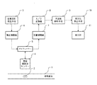
図1は、本発明の実施の形態の1例である音響異方性測定装置の概略構成を示すものであり、1は被検査体、2は超音波、3は任意波形発生手段、4は電圧増幅器、5はダイプレクサー、6は電磁超音波センサー、7は前置増幅器、8はA/D変換器、9は周波数解析手段、10は異方性算出手段、11は表示部である。
【0029】
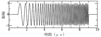
本実施の形態において、被検査体1は異方性を有する厚さ1.6mmの熱延鋼板である。まず、任意波形発生手段3は、図2に示すようなパルス幅8μs、周波数帯域0〜10MHzのチャープパルス波形を発生し、電圧増幅器4に送信する。ここでは、任意波形発生手段3の発生する波形として、周波数全域に渡ってフラットな強度のチャープパルス波形を用いているが、少なくとも被検査体の共振周波数を含む周波数帯域を、変調周波数帯域とするものであればどのようなものでもよく、センサ等の周波数特性を補うような特性を有する周波数変調をかけてもよい(これは、センサ等の周波数特性と前記(2)式におけるA{ω(t)}との積を一定にすることにより実現できる。)。
【0030】
被検査体の共振周波数としては、予め行った実験の結果から予想される範囲の音速と概略の板厚を(1)式に代入して求め、求まった範囲の周波数が変調周波数帯域に含まれるようにすればよい。パルス幅は測定時間が許されるならどれくらいの長さでもよい。
【0031】
電圧増幅器4は、送信されてきたチャープパルス波を電圧振幅±1.2kVに増幅しダイプレクサー5に送信する。ここで、電圧増幅器4の増幅度は、電磁超音波センサー6の耐圧内ならいくら増幅してもよい。
【0032】
ダイプレクサー5は、電圧増幅器4からの送信波を電磁超音波センサー6に送り、送信が終わると同時に、電磁超音波センサー6で受信される波形を、A/D変換器8に送る。
【0033】
電磁超音波センサー6は、L方向偏波の横波、及び、C方向偏波の横波を発生するように作られたものであり、ダイプレクサー5から送信波形が到達したらば、所定の偏波の横波を発生する。
【0034】
ここで、異方性の測定には、L方向偏波の横波の測定とC方向偏波の横波の測定が必要なので、電磁超音波センサー6は、一方の偏波の測定が終わると同時に偏波方向90ー変えることが可能なものにしてある。もちろん、それぞれの偏波方向の電磁超音波センサーとその他の測定機器を2つ用意しておいて、同時に両偏波の測定を行なってもよいし、一つのセンサーでL、C方向両偏波の横波を出せるようにしておいてもよい。
【0035】
電磁超音波センサー6にて被検査体への超音波送信が終わると、A/D変換器8には、ダイプレクサー5経由で、受信波形が送られてくるので、被検査体2の超音波伝播波形(Aスコープ)が得られる。
【0036】
図4(a)および図5(a)は、それぞれ、C方向偏波の横波によるAスコープとL方向偏波の横波によるAスコープである。また、図3(a)は、L方向偏波、C方向偏波の両方の横波を送信した時のAスコープである。
【0037】
周波数解析手段9は、A/D変換器8で得られたAスコープを周期解析しスペクトルを得る。図4(b)、図5(b)および図3(b)は、それぞれ、図4(a)、図5(a)及び図3(a)のAスコープをFFTして求めたスペクトルである。
【0038】
図4(b)のスペクトルはC方向偏波の横波、図5(b)のスペクトルはL方向偏波の横波、図3(b)のスペクトルは、C方向、L方向両偏波横波の板厚共振ピークを含むものである。異方性算出手段10は、このスペクトルからスペクトルのピークを検出し、共振周波数を決定し、その比から音響異方性を(3)式に従って算出し、表示部11にその結果を送る。
【0039】
異方性算出手段10の動作を詳しく説明する。まず、理解しやすくするために、C方向偏波の横波とL方向偏波の横波による測定を別々に行った場合について説明する。図4(b)および図5(b)のスペクトルピークは、(1)式の共振周波数に対応するものであり、低い周波数のピークからn=1、2.3、…を(1)式に代入すると、n番目の共振周波数と板厚と音速の関係を満たす。
【0040】
異方性算出手段10は、図4(b)および図5(b)のn番目の共振周波数を検出し、(3)式より異方性を算出している。ここで、nは何でもよい。また、隣り合う共振周波数の差は、1番目の共振周波数と等しいので、それぞれの偏波の測定を行なう場合は、隣り合う共振周波数の差を求めて、異方性を算出することもできる。
【0041】
図3(b)に示すように、一つのスペクトルにC方向、L方向両偏波横波の信号が両方入っている場合は、一般にC方向偏波の横波の共振周波数がL方向偏波の横波の共振周波数より低いことに着目して両者を区別する。たとえばn=1として、最も低い周波数帯域にある2つのピークを求め、そのうち低い周波数をにC方向偏波の横波の共振周波数、高い方をL方向偏波の横波の共振周波数とする。n=1として、両者のピークが明確に切り分けれられない場合は、そのピーク値の周波数の2倍近くの周波数にある周波数ピークに注目して、n=2として同じことを行えばよい。このようにして、ピークの区別ができるようになるまでnを順次増やしていけば両者を区別することができるようになる。
【0042】
【発明の効果】
以上説明したように本発明のうち請求項1に係る発明においては、1回の送受信で測定が完了するので、従来の方法に比較して圧倒的に短時間で共振周波数や音速を求めることができ、かつ共振法を利用しているので、被検査体の厚さが薄い場合でも測定が可能である。
請求項2に係る発明においは、送信波形にチャープ波を用いているので、高感度でかつ正確に共振周波数と音速を求めることができる。
【0043】
請求項3に係る発明においては、音響異方性の測定にあたって、請求項1又は請求項2に記載の方法で共振周波数や音速を求めているので、迅速にかつ高精度で音響異方性を求めることができる。また、被検査体の厚さが薄い場合でも測定が可能である。
【0044】
請求項4に係る発明においては、C方向偏波横波とL方向偏波横波の共振周波数又は音速を求めるのに、前記第1の手段の方法を使用しているので、迅速にかつ高精度で音響異方性を求めることができる。
請求項5に係る発明においては、送信波としてチャープパルス波を用いているので、高感度でかつ正確に共振周波数と音速を求めることができる。
【0045】
請求項6に係る発明においては、探触子として電磁超音波探触子を用いているので、非接触で金属薄板の音響異方性を測定することができ、オンラインで測定を行って、その結果を製造ラインに迅速にフィードバックすることができる。
【図面の簡単な説明】
【図1】本発明の実施の形態の1例である音響異方性測定装置の概略構成を示す図である。
【図2】送信波形として用いられるチャープ波の例を示す図である。
【図3】C方向偏波の横波とL方向偏波の横波を同時に送受信した場合の受信波形のAスコープ(a)と、そのスペクトル(b)を示す図である。
【図4】C方向偏波の横波を送受信したときのAスコープ(a)と、そのスペクトル(b)を示す図である。
【図5】L方向偏波の横波を送受信したときのAスコープ(a)と、そのスペクトル(b)を示す図である。
【符号の説明】
1…被検査体
2…超音波
3…任意波形発生手段
4…電圧増幅器
5…ダイプレクサー
6…電磁超音波センサー
7…前置増幅器
8…A/D変換器
9…周波数解析手段
10…異方性算出手段
11…表示部[0001]
BACKGROUND OF THE INVENTION
The present invention relates to a method for measuring the resonance frequency and sound velocity (ultrasonic characteristics) of ultrasonic waves in a thin metal plate, and acoustic anisotropy determined by the ratio of the ultrasonic sound velocity in the rolling direction and the direction perpendicular to the rolling direction (width direction). The present invention relates to a method and an apparatus for measuring.
[0002]
[Prior art]
A steel sheet rolled at a relatively low finish rolling temperature usually has material anisotropy. This material anisotropy is particularly significant in the rolling direction of steel (hereinafter referred to as L direction) and in the direction orthogonal to the rolling direction (sheet width direction: hereinafter referred to as C direction). This is because the steel structure after finish rolling has developed a ferrite structure having a significant difference in the L and C directions, a so-called texture.
[0003]
In order to prevent the occurrence of such material anisotropy, the degree of anisotropy may be detected during finish rolling, and the finish rolling temperature of the steel material having a correlation therewith may be controlled in detail. As one method for determining the degree of anisotropy, a method for measuring acoustic anisotropy is disclosed in Japanese Patent Application Laid-Open No. 62-223665. According to the present invention, the transverse wave pulse polarized in the L direction and the transverse wave pulse polarized in the C direction are propagated in the plate thickness direction, and the acoustic anisotropy is calculated from the difference between the round-trip propagation times.
[0004]
[Problems to be solved by the invention]
However, since the method of the above invention propagates the pulse wave in the thickness direction of the steel sheet and calculates the propagation time from the repetition of the reflected echo, the reflected echoes that are repeatedly reflected are superimposed when the thickness is reduced. As a result, the propagation time cannot be measured. Therefore, a measurement method using an electromagnetic ultrasonic resonance method has been proposed.
[0005]
As represented by the method disclosed in Japanese Patent Application Laid-Open No. 7-286995, this method is maximized by the fact that the ultrasonic wave generated from the electromagnetic ultrasonic sensor causes the thickness resonance of the object to be inspected at a specific frequency. The resonance frequency is obtained by utilizing the following property. That is, the sound speed can be obtained by utilizing the fact that the resonance frequency fr is expressed by the following equation (1).
f r = n ・ v / (2d)… (1)
Here, n is a positive integer, v is the speed of sound, and d is the plate thickness.
[0006]
Unlike the method using the pulse propagation time measurement, such an electromagnetic ultrasonic resonance method can measure the speed of sound even when the plate thickness is thin, and thus can measure the anisotropy of a thin metal plate. However, in order to determine the resonance frequency, transmission / reception with a burst wave or continuous wave having a very long time width and a frequency sweeping operation performed simultaneously with this transmission / reception are required, which causes a problem that the measurement time becomes very long. appear.
[0007]
This problem is caused by the fact that the transmission time of the transmission wave cannot be shortened. That is, the transmission time Δt of the transmission wave is determined by the frequency resolution Δf, and it is necessary to satisfy Δt >> 1 / Δf. For example, if a burst wave with a width of 1 ms is swept over 0 to 10 MHz every 100 kHz, 100 ms is required only for the transmission time. Usually, a metal sheet manufacturing line has a line speed of 1 to 5 m per second, so it is useless if it takes 100 ms for measurement.
[0008]
The present invention has been made in view of the above circumstances, and it is an object of the present invention to propose a method and an apparatus capable of measuring ultrasonic resonance frequency, ultrasonic sound velocity, and acoustic anisotropy in a thin metal plate with high accuracy and in a short time. And
[0009]
[Means for Solving the Problems]
A first means for solving the above problem is a method for measuring the characteristics of ultrasonic waves propagating in the thickness direction of a thin metal plate, and a plurality of resonances including higher orders within a pulse width as a transmission pulse wave. Frequency analysis is performed over a predetermined frequency band in which a frequency group is generated, and the received waveform obtained after transmission is subjected to frequency analysis using a waveform including a frequency that causes plate thickness resonance in a metal thin plate as a measurement object as a modulation frequency, Obtaining a plurality of resonance frequency groups from the spectrum obtained by frequency analysis, selecting a resonance frequency capable of determining a sound velocity from the resonance frequency groups, and measuring a sound velocity of the material based on the selected resonance frequency. An ultrasonic characteristic measuring method (claim 1).
[0010]
In this means, a technique is adopted in which a broadband pulse wave is transmitted to an object to be inspected, a spectrum of the received wave is obtained by frequency analysis such as FFT, and the resonance frequency is determined. Here, it is conceivable that the transmission wave is simply an impulse wave. However, since an impulse wave includes all frequencies in one pulse, the intensity of each frequency component becomes low. Therefore, in the present invention, a waveform that is frequency-modulated over a predetermined frequency band within a pulse width and includes a frequency that causes plate thickness resonance in a metal thin plate that is a measurement object is used as the modulation frequency.
[0011]
Of course, since the frequency that causes the plate thickness resonance in the metal thin plate that is actually the object to be measured is unknown, it cannot be accurately determined before the measurement. Here, “the modulation frequency causing the plate thickness resonance in the thin metal plate to be measured” is assumed to be the range of sound speed expected in the thin metal plate to be measured, and the plate thickness resonance is caused in that range. This refers to the modulation frequency, which is a modulation frequency having a certain band range. That is, a transmission waveform that is frequency-modulated over at least this band range is used.
[0012]
That is, the transmission waveform is represented by the following equation (2).
S (t) = δ (t) ・ A {ω (t)} ・ sin {ω (t) ・ t}… (2)
Here, t is a time, δ (t) is a function that is 1 when 0 ≦ t ≦ W (W is a pulse width), and 0 otherwise, ω (t) is a function of frequency and time. That is, the sin wave waveform included in the pulse with the pulse width W changes the frequency ω with time (the modulation frequency is this ω), and the amplitude A {ω (t) at that time } Also changes with ω.
[0013]
If such a transmitted wave is transmitted toward a thin metal plate and the spectrum of the received wave is obtained, the peak of the spectrum appears at the frequency at which resonance actually occurs (corresponding to the above ω). Can do. Since the plate thickness is known in advance, the ultrasonic speed of sound can be obtained from equation (1).
[0014]
In this means, since the measurement is completed by one transmission and reception, even when using electromagnetic ultrasonic waves, the resonance frequency and sound speed can be obtained in an overwhelmingly short time compared to the conventional electromagnetic ultrasonic resonance method. And having the same sensitivity as that of the conventional electromagnetic ultrasonic resonance method.
[0015]
A second means for solving the problem is the first means, wherein the transmission pulse wave is a chirp pulse wave (claim 2).
[0016]
In the first means, if a chirped pulse wave is used as a transmission wave, a transmission wave with high sensitivity and a flat frequency intensity distribution can be obtained. For example, compared with the intensity of each frequency component included in an impulse wave with a voltage amplitude of ± 1 kV and a pulse width of 0.1 μs, each frequency component included in a chirp pulse wave with a voltage amplitude of ± 1 kV, a pulse width of 5 μs, and 0 to 10 MHz. Of course, the high strength is easily understood. Therefore, in this means, the resonance frequency and the sound speed can be obtained with high sensitivity and accuracy.
[0017]
In this means, in Eq. (2), this corresponds to a constant A {ω (t)}, typically,
ω (t) = B ・ t + C
Is equivalent to However, B and C are constants.
[0018]
The third means for solving the above-mentioned problem is the ratio of the sound velocity of the transverse wave polarized in the direction perpendicular to the sheet metal rolling direction (C direction) and the sound velocity of the transverse wave polarized in the rolling direction (L direction). A method for measuring acoustic anisotropy, using the method of the first means or the second means, and a resonance frequency group of transverse waves polarized in the C direction and resonance of transverse waves polarized in the L direction. Based on the frequency group, a resonance frequency that can determine the sound velocity is obtained, the sound velocity of the material is obtained based on the obtained resonance frequency, and the acoustic anisotropy is measured from these ratios. This is a directionality measurement method (claim 3).
[0019]
The acoustic anisotropy is given by the following equation (3).
Acoustic anisotropy = V C / V L = f rc / f rL … (3)
Here, V C is the sound velocity of the C-direction polarization transverse wave, V L is the sound velocity of the L-direction polarization transverse wave, frC is the resonance frequency of the C-direction polarization transverse wave, and frr is the resonance frequency of the L-direction polarization transverse wave. . In this means, the first means or the second means is used to obtain these V C , V L or f rC , f rL . Therefore, the acoustic anisotropy can be obtained quickly and with high accuracy.
[0020]
A fourth means for solving the above-mentioned problem is that a metal thin plate that is frequency-modulated over a predetermined frequency band in which a plurality of resonance frequency groups including higher order are generated within a pulse width and is a measured object as a modulation frequency A signal generator that generates a signal having a waveform including a frequency that causes a plate thickness resonance, and a transverse wave ultrasonic wave having a waveform corresponding to the signal waveform from the signal generator, wherein two types of supersonic waves having different planes of polarization are 90 ° A probe capable of generating and receiving sound waves, a frequency analysis means for obtaining a spectrum by frequency analysis of the received ultrasonic signal, and a resonance frequency capable of determining a sound velocity from a plurality of resonance frequency groups in the obtained spectrum And an acoustic anisotropy calculating means for calculating an acoustic anisotropy from the obtained resonance frequency based on the obtained resonance frequency. ( Motomeko 4).
[0021]
In this means, a signal generator is used to generate a signal having a waveform that is frequency-modulated over a predetermined frequency band within a pulse width and includes a frequency that causes a plate thickness resonance in a metal thin plate as a measured object as a modulation frequency, Amplify as necessary and apply to the ultrasound probe. The ultrasonic probe generates an ultrasonic wave corresponding to this signal, that is, an ultrasonic wave having a waveform that faithfully reproduces the signal waveform, and makes it incident on a metal thin plate that is a measurement object. Since the ultrasonic probe can generate two types of ultrasonic waves whose polarization planes are different by 90 °, the C-direction polarization transverse wave and the L-direction polarization transverse wave are generated simultaneously or by switching. Like that. As such an ultrasonic probe, a probe in which a probe capable of transmitting / receiving a C-direction polarized transverse wave and a probe capable of transmitting / receiving an L-direction polarized transverse wave are accommodated in one casing may be used.
[0022]
The frequency analysis means performs frequency analysis of the received waveform and obtains a spectrum of the received waveform. The acoustic anisotropy calculating means obtains the resonance frequency or sound velocity from the obtained spectrum, and uses the equation (3) to calculate the acoustic anisotropy from the relationship between the resonance frequency or sound velocity of the C-direction polarization transverse wave and the L-direction polarization transverse wave. Measure sex.
[0023]
In this means, since the method of the first means is used to obtain the resonance frequency or sound velocity of the C-direction polarization transverse wave and the L-direction polarization transverse wave, the acoustic anisotropy can be obtained quickly and accurately. Can be requested.
[0024]
A fifth means for solving the above problem is the fourth means, wherein the transmission wave generated by the signal generator is a chirp pulse wave (claim 4).
[0025]
In this means, since a chirped pulse wave is used as the transmission wave, as described in the explanation of the second means, the resonance frequency and sound speed can be obtained with high sensitivity and accuracy.
[0026]
Sixth means for solving the problem is the fourth means or the fifth means, wherein the probe is an electromagnetic ultrasonic probe (claim). 6).
[0027]
In this means, since the electromagnetic ultrasonic probe is used as the probe, the acoustic anisotropy of the metal thin plate can be measured in a non-contact manner, the measurement is performed online, and the result is obtained on the production line. Can provide quick feedback.
[0028]
DETAILED DESCRIPTION OF THE INVENTION
Hereinafter, examples of embodiments of the present invention will be described with reference to the drawings.
FIG. 1 shows a schematic configuration of an acoustic anisotropy measuring apparatus which is an example of an embodiment of the present invention. Reference numeral 1 denotes an object to be inspected, 2 an ultrasonic wave, 3 an arbitrary waveform generating means, and 4 a Voltage amplifier, 5 is a diplexer, 6 is an electromagnetic ultrasonic sensor, 7 is a preamplifier, 8 is an A / D converter, 9 is frequency analysis means, 10 is anisotropy calculation means, and 11 is a display unit.
[0029]
In the present embodiment, the inspection object 1 is a hot-rolled steel sheet having anisotropy and a thickness of 1.6 mm. First, the arbitrary waveform generating means 3 generates a chirp pulse waveform having a pulse width of 8 μs and a frequency band of 0 to 10 MHz as shown in FIG. Here, a chirp pulse waveform having a flat intensity over the entire frequency is used as the waveform generated by the arbitrary waveform generating means 3, but at least the frequency band including the resonance frequency of the device under test is used as the modulation frequency band. Any one may be used, and frequency modulation having a characteristic that supplements the frequency characteristic of the sensor or the like may be applied (this is the frequency characteristic of the sensor or the like and A {ω ( It can be realized by making the product of t)} constant.)
[0030]
The resonance frequency of the object to be inspected is obtained by substituting the sound speed and approximate plate thickness in the range expected from the result of the experiment conducted in advance into equation (1), and the frequency in the obtained range is included in the modulation frequency band. What should I do? The pulse width can be as long as measurement time is allowed.
[0031]
The
[0032]
The
[0033]
The electromagnetic
[0034]
Here, since the measurement of the anisotropy requires the measurement of the transverse wave of the L-direction polarization and the measurement of the transverse wave of the C-direction polarization, the electromagnetic
[0035]
When the ultrasonic transmission to the inspected object is completed by the electromagnetic
[0036]
FIG. 4A and FIG. 5A are an A scope using a C direction polarized wave and an A scope using an L direction polarized wave. FIG. 3A shows an A scope when both transverse waves of L direction polarization and C direction polarization are transmitted.
[0037]
The frequency analysis means 9 periodically analyzes the A scope obtained by the A /
[0038]
The spectrum of FIG. 4 (b) is a transverse wave of C direction polarization, the spectrum of FIG. 5 (b) is a transverse wave of L direction polarization, and the spectrum of FIG. 3 (b) is a plate of both polarization waves of C direction and L direction. It includes a thick resonance peak. The anisotropy calculation means 10 detects the peak of the spectrum from this spectrum, determines the resonance frequency, calculates the acoustic anisotropy from the ratio according to the equation (3), and sends the result to the
[0039]
The operation of the anisotropy calculation means 10 will be described in detail. First, in order to facilitate understanding, a case will be described in which measurement is performed separately using a transverse wave of C-direction polarization and a transverse wave of L-direction polarization. The spectral peaks in FIGS. 4B and 5B correspond to the resonance frequency of the equation (1), and substituting n = 1, 2.3,... From the low frequency peak into the equation (1). Satisfy the relationship among the nth resonance frequency, the plate thickness, and the sound velocity.
[0040]
The anisotropy calculating means 10 detects the nth resonance frequency in FIGS. 4B and 5B and calculates the anisotropy from the equation (3). Here, n may be anything. Further, since the difference between the adjacent resonance frequencies is equal to the first resonance frequency, when measuring each polarization, the difference between the adjacent resonance frequencies can be obtained to calculate the anisotropy.
[0041]
As shown in FIG. 3B, in the case where both signals in both the C-direction and L-direction polarized waves are included in one spectrum, the resonance frequency of the transverse wave in the C-direction polarization is generally the transverse wave in the L-direction polarization. Focusing on the fact that the resonance frequency is lower than the resonance frequency, the two are distinguished. For example, assuming that n = 1, two peaks in the lowest frequency band are obtained, and the lower frequency is set as the resonance frequency of the transverse wave of the C direction polarization, and the higher one is set as the resonance frequency of the transverse wave of the L direction polarization. If n = 1 and the peaks of both cannot be clearly separated, paying attention to the frequency peak at a frequency close to twice the frequency of the peak value, the same can be done with n = 2. In this way, if n is sequentially increased until the peaks can be distinguished, the two can be distinguished.
[0042]
【The invention's effect】
As described above, in the invention according to claim 1 of the present invention, since the measurement is completed by one transmission and reception, it is possible to obtain the resonance frequency and sound speed in an overwhelmingly short time compared to the conventional method. Since the resonance method is used, measurement is possible even when the object to be inspected is thin.
In the invention according to claim 2, since the chirp wave is used for the transmission waveform, the resonance frequency and the sound speed can be obtained with high sensitivity and accuracy.
[0043]
In the invention according to claim 3, since the resonance frequency and sound speed are obtained by the method according to claim 1 or 2 when measuring the acoustic anisotropy, the acoustic anisotropy is quickly and accurately determined. Can be sought. In addition, measurement is possible even when the object to be inspected is thin.
[0044]
In the invention according to
In the invention according to
[0045]
In the invention according to
[Brief description of the drawings]
FIG. 1 is a diagram showing a schematic configuration of an acoustic anisotropy measuring apparatus which is an example of an embodiment of the present invention.
FIG. 2 is a diagram illustrating an example of a chirp wave used as a transmission waveform.
FIG. 3 is a diagram showing an A scope (a) of a received waveform and a spectrum (b) when a transverse wave of C direction polarization and a transverse wave of L direction polarization are transmitted and received at the same time.
FIG. 4 is a diagram showing an A scope (a) and a spectrum (b) when a transverse wave of C direction polarization is transmitted and received.
FIG. 5 is a diagram showing an A scope (a) and a spectrum (b) when a transverse wave of L-direction polarization is transmitted and received.
[Explanation of symbols]
DESCRIPTION OF SYMBOLS 1 ... Test object 2 ... Ultrasound 3 ... Arbitrary waveform generation means 4 ...
Claims (6)
Priority Applications (1)
| Application Number | Priority Date | Filing Date | Title |
|---|---|---|---|
| JP2000204452A JP4617540B2 (en) | 2000-07-06 | 2000-07-06 | Ultrasonic characteristic measuring method, acoustic anisotropy measuring method, and acoustic anisotropy measuring apparatus |
Applications Claiming Priority (1)
| Application Number | Priority Date | Filing Date | Title |
|---|---|---|---|
| JP2000204452A JP4617540B2 (en) | 2000-07-06 | 2000-07-06 | Ultrasonic characteristic measuring method, acoustic anisotropy measuring method, and acoustic anisotropy measuring apparatus |
Publications (2)
| Publication Number | Publication Date |
|---|---|
| JP2002022711A JP2002022711A (en) | 2002-01-23 |
| JP4617540B2 true JP4617540B2 (en) | 2011-01-26 |
Family
ID=18701709
Family Applications (1)
| Application Number | Title | Priority Date | Filing Date |
|---|---|---|---|
| JP2000204452A Expired - Fee Related JP4617540B2 (en) | 2000-07-06 | 2000-07-06 | Ultrasonic characteristic measuring method, acoustic anisotropy measuring method, and acoustic anisotropy measuring apparatus |
Country Status (1)
| Country | Link |
|---|---|
| JP (1) | JP4617540B2 (en) |
Families Citing this family (2)
| Publication number | Priority date | Publication date | Assignee | Title |
|---|---|---|---|---|
| CN102706965B (en) * | 2012-06-12 | 2014-08-27 | 西安邮电大学 | Novel accurate measuring method of anisotropic parameter of rock |
| CN113311073B (en) * | 2021-04-21 | 2022-12-02 | 武汉科技大学 | Electromagnetic ultrasonic sound time measuring method and system |
Citations (2)
| Publication number | Priority date | Publication date | Assignee | Title |
|---|---|---|---|---|
| JPH07286995A (en) * | 1994-04-20 | 1995-10-31 | Nippon Steel Corp | Electromagnetic ultrasonic wave transmitting and receiving method and device therefor |
| JPH10505408A (en) * | 1994-05-12 | 1998-05-26 | サザン・リサーチ・インスティテュート | Ultrasonic spectroscopy material inspection method and apparatus |
Family Cites Families (3)
| Publication number | Priority date | Publication date | Assignee | Title |
|---|---|---|---|---|
| JPS63150663A (en) * | 1986-12-15 | 1988-06-23 | Nkk Corp | Acoustic anisotropy measuring instrument for steel plate |
| JPH02296147A (en) * | 1989-05-10 | 1990-12-06 | Nkk Corp | Method and apparatus for measuring acoustic anisotropy |
| JP3575252B2 (en) * | 1997-11-13 | 2004-10-13 | Jfeスチール株式会社 | Electromagnetic ultrasonic measurement method and apparatus |
-
2000
- 2000-07-06 JP JP2000204452A patent/JP4617540B2/en not_active Expired - Fee Related
Patent Citations (2)
| Publication number | Priority date | Publication date | Assignee | Title |
|---|---|---|---|---|
| JPH07286995A (en) * | 1994-04-20 | 1995-10-31 | Nippon Steel Corp | Electromagnetic ultrasonic wave transmitting and receiving method and device therefor |
| JPH10505408A (en) * | 1994-05-12 | 1998-05-26 | サザン・リサーチ・インスティテュート | Ultrasonic spectroscopy material inspection method and apparatus |
Also Published As
| Publication number | Publication date |
|---|---|
| JP2002022711A (en) | 2002-01-23 |
Similar Documents
| Publication | Publication Date | Title |
|---|---|---|
| US6122968A (en) | Delay line for an ultrasonic probe and method of using same | |
| JP2010266378A (en) | Ultrasonic diagnosis/evaluation system | |
| Goujon et al. | Behaviour of acoustic emission sensors using broadband calibration techniques | |
| Giurgiutiu et al. | Embedded-ultrasonics structural radar for nondestructive evaluation of thin-wall structures | |
| US20210293947A1 (en) | Continuous wave ultrasound or acoustic non-destructive testing | |
| JP4625747B2 (en) | Piping inspection device and piping inspection method | |
| US6494097B1 (en) | Method and apparatus for measuring thickness of a layer in a multi-layered object | |
| JP4534309B2 (en) | Method for measuring thickness resonance spectrum of metal thin plate and method for measuring electromagnetic ultrasonic wave of metal thin plate | |
| JPS6156450B2 (en) | ||
| US5672828A (en) | Strength determination of sheet materials by utrasonic testing | |
| JP4617540B2 (en) | Ultrasonic characteristic measuring method, acoustic anisotropy measuring method, and acoustic anisotropy measuring apparatus | |
| US20110048134A1 (en) | Ultrasonic diagnostic apparatus | |
| JP2000241397A (en) | Method and apparatus for detecting surface defect | |
| JP2697508B2 (en) | Ultrasonic thickness measurement method of furnace wall | |
| US20230081998A1 (en) | Stress gradient high-efficiency non-destructive detection system based on frequency domain calculation of broadband swept frequency signals, and detection method thereof | |
| JPH04323553A (en) | Method and device for ultrasonic resonance flaw detection | |
| JPH08201356A (en) | Sonic velocity measuring method for solid material and ultrasonic probe | |
| JPH0313859A (en) | Method for measuring compressive strength of concrete using ultrasonic wave | |
| JP5059344B2 (en) | Plate thickness measuring apparatus and measuring method | |
| JP2792286B2 (en) | Method for measuring elastic constant of specimen | |
| JP2626361B2 (en) | Ultrasonic phase velocity curve determination method and apparatus | |
| JP4411734B2 (en) | Hot ultrasonic thickness gauge and thickness measurement method | |
| JP2001343366A (en) | Crystal grain measuring method and device for metal sheet | |
| Miqueleti et al. | Acoustic impedance measurement method using spherical waves | |
| JP3037897B2 (en) | Ear ratio measurement method for thin metal plates |
Legal Events
| Date | Code | Title | Description |
|---|---|---|---|
| A621 | Written request for application examination |
Free format text: JAPANESE INTERMEDIATE CODE: A621 Effective date: 20070528 |
|
| RD01 | Notification of change of attorney |
Free format text: JAPANESE INTERMEDIATE CODE: A7421 Effective date: 20080707 |
|
| A131 | Notification of reasons for refusal |
Free format text: JAPANESE INTERMEDIATE CODE: A131 Effective date: 20100413 |
|
| A521 | Written amendment |
Free format text: JAPANESE INTERMEDIATE CODE: A523 Effective date: 20100603 |
|
| A131 | Notification of reasons for refusal |
Free format text: JAPANESE INTERMEDIATE CODE: A131 Effective date: 20100706 |
|
| A521 | Written amendment |
Free format text: JAPANESE INTERMEDIATE CODE: A523 Effective date: 20100903 |
|
| TRDD | Decision of grant or rejection written | ||
| A01 | Written decision to grant a patent or to grant a registration (utility model) |
Free format text: JAPANESE INTERMEDIATE CODE: A01 Effective date: 20100928 |
|
| A01 | Written decision to grant a patent or to grant a registration (utility model) |
Free format text: JAPANESE INTERMEDIATE CODE: A01 |
|
| A61 | First payment of annual fees (during grant procedure) |
Free format text: JAPANESE INTERMEDIATE CODE: A61 Effective date: 20101011 |
|
| FPAY | Renewal fee payment (event date is renewal date of database) |
Free format text: PAYMENT UNTIL: 20131105 Year of fee payment: 3 |
|
| R150 | Certificate of patent or registration of utility model |
Free format text: JAPANESE INTERMEDIATE CODE: R150 |
|
| LAPS | Cancellation because of no payment of annual fees |