JP4616975B2 - Inkjet printing method and apparatus - Google Patents
Inkjet printing method and apparatus Download PDFInfo
- Publication number
- JP4616975B2 JP4616975B2 JP2000266159A JP2000266159A JP4616975B2 JP 4616975 B2 JP4616975 B2 JP 4616975B2 JP 2000266159 A JP2000266159 A JP 2000266159A JP 2000266159 A JP2000266159 A JP 2000266159A JP 4616975 B2 JP4616975 B2 JP 4616975B2
- Authority
- JP
- Japan
- Prior art keywords
- ink
- recording
- color material
- printability improving
- image data
- Prior art date
- Legal status (The legal status is an assumption and is not a legal conclusion. Google has not performed a legal analysis and makes no representation as to the accuracy of the status listed.)
- Expired - Fee Related
Links
Images


Classifications
-
- B—PERFORMING OPERATIONS; TRANSPORTING
- B41—PRINTING; LINING MACHINES; TYPEWRITERS; STAMPS
- B41J—TYPEWRITERS; SELECTIVE PRINTING MECHANISMS, i.e. MECHANISMS PRINTING OTHERWISE THAN FROM A FORME; CORRECTION OF TYPOGRAPHICAL ERRORS
- B41J2/00—Typewriters or selective printing mechanisms characterised by the printing or marking process for which they are designed
- B41J2/005—Typewriters or selective printing mechanisms characterised by the printing or marking process for which they are designed characterised by bringing liquid or particles selectively into contact with a printing material
- B41J2/01—Ink jet
- B41J2/015—Ink jet characterised by the jet generation process
- B41J2/04—Ink jet characterised by the jet generation process generating single droplets or particles on demand
- B41J2/045—Ink jet characterised by the jet generation process generating single droplets or particles on demand by pressure, e.g. electromechanical transducers
- B41J2/04501—Control methods or devices therefor, e.g. driver circuits, control circuits
- B41J2/04508—Control methods or devices therefor, e.g. driver circuits, control circuits aiming at correcting other parameters
-
- B—PERFORMING OPERATIONS; TRANSPORTING
- B41—PRINTING; LINING MACHINES; TYPEWRITERS; STAMPS
- B41J—TYPEWRITERS; SELECTIVE PRINTING MECHANISMS, i.e. MECHANISMS PRINTING OTHERWISE THAN FROM A FORME; CORRECTION OF TYPOGRAPHICAL ERRORS
- B41J2/00—Typewriters or selective printing mechanisms characterised by the printing or marking process for which they are designed
- B41J2/005—Typewriters or selective printing mechanisms characterised by the printing or marking process for which they are designed characterised by bringing liquid or particles selectively into contact with a printing material
- B41J2/01—Ink jet
- B41J2/015—Ink jet characterised by the jet generation process
- B41J2/04—Ink jet characterised by the jet generation process generating single droplets or particles on demand
- B41J2/045—Ink jet characterised by the jet generation process generating single droplets or particles on demand by pressure, e.g. electromechanical transducers
- B41J2/04501—Control methods or devices therefor, e.g. driver circuits, control circuits
- B41J2/0451—Control methods or devices therefor, e.g. driver circuits, control circuits for detecting failure, e.g. clogging, malfunctioning actuator
-
- B—PERFORMING OPERATIONS; TRANSPORTING
- B41—PRINTING; LINING MACHINES; TYPEWRITERS; STAMPS
- B41J—TYPEWRITERS; SELECTIVE PRINTING MECHANISMS, i.e. MECHANISMS PRINTING OTHERWISE THAN FROM A FORME; CORRECTION OF TYPOGRAPHICAL ERRORS
- B41J2/00—Typewriters or selective printing mechanisms characterised by the printing or marking process for which they are designed
- B41J2/005—Typewriters or selective printing mechanisms characterised by the printing or marking process for which they are designed characterised by bringing liquid or particles selectively into contact with a printing material
- B41J2/01—Ink jet
- B41J2/015—Ink jet characterised by the jet generation process
- B41J2/04—Ink jet characterised by the jet generation process generating single droplets or particles on demand
- B41J2/045—Ink jet characterised by the jet generation process generating single droplets or particles on demand by pressure, e.g. electromechanical transducers
- B41J2/04501—Control methods or devices therefor, e.g. driver circuits, control circuits
- B41J2/0458—Control methods or devices therefor, e.g. driver circuits, control circuits controlling heads based on heating elements forming bubbles
-
- B—PERFORMING OPERATIONS; TRANSPORTING
- B41—PRINTING; LINING MACHINES; TYPEWRITERS; STAMPS
- B41J—TYPEWRITERS; SELECTIVE PRINTING MECHANISMS, i.e. MECHANISMS PRINTING OTHERWISE THAN FROM A FORME; CORRECTION OF TYPOGRAPHICAL ERRORS
- B41J2/00—Typewriters or selective printing mechanisms characterised by the printing or marking process for which they are designed
- B41J2/005—Typewriters or selective printing mechanisms characterised by the printing or marking process for which they are designed characterised by bringing liquid or particles selectively into contact with a printing material
- B41J2/01—Ink jet
- B41J2/015—Ink jet characterised by the jet generation process
- B41J2/04—Ink jet characterised by the jet generation process generating single droplets or particles on demand
- B41J2/045—Ink jet characterised by the jet generation process generating single droplets or particles on demand by pressure, e.g. electromechanical transducers
- B41J2/04501—Control methods or devices therefor, e.g. driver circuits, control circuits
- B41J2/04581—Control methods or devices therefor, e.g. driver circuits, control circuits controlling heads based on piezoelectric elements
Description
【0001】
【発明の属する技術分野】
本発明は、複数のインク吐出口を配列して成る記録ヘッドを用い、色材を含有する色材インクとプリント性を向上するための液体(以下プリント性向上インクという)とを用いて記録媒体上に画像記録を行うインクジェットプリント方法および装置に関する。本発明は、紙や布、革、不織布、OHP用紙等、さらには金属などの記録媒体を用いる機器すべてに適用可能である。具体的な適用機器としては、プリンタ、複写機、ファクシミリ等の事務機器や工業用生産機器等を挙げることができる。
【0002】
【従来の技術】
複写装置や、ワードプロセッサ、コンピュータ等の情報処理機器、さらには通信機器の普及に伴い、それらの機器の画像形成(記録)のための出力装置の一つであるインクジェット記録装置が急速に普及している。
【0003】
このようなインクジェット記録装置においては、記録ヘッドとしては、記録速度の向上のために複数のインク吐出ノズルが集積配列され、かつインク吐出口およびインク液路が複数集積されたものが用いられている。さらに近年ではカラー対応が進むにつれ、複数個の記録ヘッドを備えたものも多くある。
【0004】
インクジェット記録方式は、記録液であるインクを飛翔させて紙等の記録媒体に着弾させてドット記録を行うもので、非接触方式であるために低騒音である。また、インク吐出ノズルの高密度化によって高解像度化・高速記録化が可能であり、さらに普通紙等の記録媒体に対しても現象や定着などの格別な処理を要せず、低価格で高品位な画像を得ることが可能であることから、近年ではその用途が広く普及しつつある。
【0005】
特に、オンデマンド型のインクジェット記録装置はそのカラー化が容易で、しかも装置自体の小型化、簡略化が可能なことから、将来の広範な需要について有望視されている。また、上述のようなカラー化の普及につれて、高画質化と高速化が益々要求されている。
【0006】
このようなインクジェット記録方式においては、記録媒体上の色材ドットの状態を改善し画品位を高める作用すなわちプリント性を向上する作用を持つプリント性向上インクを用いた手法が提案されている。このプリント性向上インクは、色材インク中の色材を不溶化させる化合物を含む無色または淡色の液体であり、記録媒体上で色材インクと混合および/または反応させることにより、耐水性や耐候性等を向上させて信頼性の高い画質を得るとともに、フェザリングや色間のブリードを少なくしてプリント濃度の高い高画質を得るために用いる。
【0007】
【発明が解決しようとする課題】
しかしながら、従来のインクジェット記録方式においては、上記プリント性向上インクを用いた場合でも、つぎのような課題がある。
【0008】
複数のインク吐出ノズルを集積配列してなる記録ヘッドを用いる場合、ある一つまたは複数の吐出ノズルが目詰まりを起こしたり、あるいは何らかの原因で駆動できなくなったときには、このような吐出ノズルからはインクを吐出させることができず、印字すべきドットが記録媒体上で印字できなくなり、結果的に主走査方向に延びる白スジが画像上に発生して、画品位を著しく低下させる。
【0009】
また、その吐出状態が他の正常なノズルの吐出状態と著しく異なる不良ノズルが何らかの原因によって生じた場合にも、白スジあるいは濃度の不均一によるスジが画像上に発生し、これもまた画品位を著しく損なっていた。
【0010】
このようなスジは特に、マルチパス印字を行わない場合、あるいは少ないパス数のマルチパス印字の際に顕著である。
【0011】
そこで従来は、このような不吐出あるいは不良ノズルが発生した場合には、ノズルのクリーニング機構によって不吐出、不良ノズルの回復を試みたりしていた。また、複数のパスで1ラインの印字を完成するマルチパス印字方法を用いる場合には、相互補完するノズルで不吐出、不良ノズルの代替を行うなどの手法を用いていた。
【0012】
しかしながら、マルチパス印字方式では、紙送り量を使用ノズルの1/nにし、主走査時に1/nに相補的に間引いたデータでn回印字することで、1ラスタラインを複数(n個)のノズルを用いて印字するので、印字時間がその分多くかかってしまう問題を有している。また、クリーニングによる回復では、時間がかかる、インクの消費を伴うなどコストアップにつながり易いという問題がある。また、不吐出、不良ノズルが発生した記録ヘッドを簡単に交換するというのでは、エコロジーの観点からも望ましくない。
【0013】
今後のインクジェット記録装置に必要なことは、更なる高画質化に加え、高速化、低コスト化を同時に実現することである。そのためにも、上記のような課題を解決することが重要である。
【0014】
本発明は上記した点に鑑みてなされたものであり、異常(不吐出、不良)ノズルが生じた場合でも、白スジをはじめとする画品位の低下をなくして、スムーズなグラデーションを持つ画像記録を簡単な処理でなし得るインクジェットプリント方法及び装置を提供することを解決課題とする。
【0015】
【課題を解決するための手段】
上記目的を達成するための本発明の一形態では、インクジェットプリント方法は、複数のインク吐出口が配列されて色材インクを吐出する色材インク用の記録ヘッドと、複数のインク吐出口が配列されてプリント性向上インクを吐出するプリント性向上インク用の記録ヘッドとを用い、これら記録ヘッドから色材インクおよびプリント性向上インクを記録媒体に吐出して、入力される画像データに応じた画像を記録媒体上に形成するインクジェットプリント方法において、前記色材インク用の記録ヘッドの複数のインク吐出口のうち吐出状態の劣化した異常インク吐出口を特定する第1ステップと、該特定された前記異常インク吐出口を除くインク吐出口に関する画像データに基づき前記プリント性向上インクを付与するためのデータを生成するとともに、前記特定された前記異常インク吐出口に隣接するインク吐出口に関する画像データがドットの記録を示すデータであることに基づき、前記異常インク吐出口に対応して記録されるラインの中の前記プリント性向上インクを付与するデータを生成して前記プリント性向上インクを付与する第2ステップと、からなり、前記異常インク吐出口を除くインク吐出口に関する画像データと、前記第2ステップで生成した前記プリント性向上インクを付与するためのデータとに基づいて、記録媒体上にインクとプリント性向上インクを付与して記録を行うことを特徴とする。
【0016】
また、例えば、前記第2のステップでは、異常インク吐出口の近傍のインク吐出口に関する画像データに基づき異常インク吐出口に対応する記録ラインおよび該記録ラインの前後の各少なくとも1つの記録ラインにおけるプリント性向上インクを付与するドットを選択し、該選択したドットにプリント性向上インクを付与することを特徴とする。
【0017】
またこの発明の他の実施形態では、インクジェットプリント装置は、複数のインク吐出口が配列されて色材インクを吐出する色材インク用の記録ヘッドと、複数のインク吐出口が配列されてプリント性向上インクを吐出するプリント性向上インク用の記録ヘッドとを用い、これら記録ヘッドから色材インクおよびプリント性向上インクを記録媒体に吐出して、入力される画像データに応じた画像を記録媒体上に形成するインクジェットプリント装置において、前記色材インク用の記録ヘッドの複数のインク吐出口のうち吐出状態の劣化した異常インク吐出口を特定する特定手段と、該特定された前記異常インク吐出口を除くインク吐出口に関する画像データに基づき前記プリント性向上インクを付与するためのデータを生成するとともに、前記特定された前記異常インク吐出口に隣接するインク吐出口に関する画像データがドットの記録を示すデータであることに基づき、前記異常インク吐出口に対応して記録されるラインの中の前記プリント性向上インクを付与するデータを生成して前記プリント性向上インクを付与する制御手段と、からなり、前記異常インク吐出口を除くインク吐出口に関する画像データと、前記制御手段で生成した前記プリント性向上インクを付与するためのデータとに基づいて、記録媒体上にインクとプリント性向上インクを付与して記録を行うことを特徴とする。
【0018】
【発明の実施の形態】
以下、図面を参照して本発明の実施形態を詳細に説明する。
【0019】
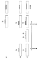
図1は、本発明に係るインクジェット記録装置の一実施形態の概略構成を示す平面図である。
【0020】
図1において、キャリッジ20上には複数のインクジェットヘッド(記録ヘッド)21−1〜21−5が搭載されており、各インクジェットヘッド21には、図2に示すように、インクを吐出するためのインク吐出口108が複数配列されている。21−1,21−2,21−3,21−4,21−5は夫々、ブラック(K)、プリント性向上インク(P)、シアン(C)、マゼンタ(M)、イエロー(Y)のインクを吐出するためのインクジェットヘッドである。
【0021】
この場合、図2に示すように、プリント性向上インク(P)を吐出する記録ヘッド21−2は、32個のインク吐出口108を有し、各インク吐出口108は二列ジグザグ状に配列されている。すなわち、一方の列のインク吐出口108の中間に、他方の列のインク吐出口108が配置されている。色材インク用の記録ヘッド21−1、21−3、…も同様であり、32個のインク吐出口108が二列ジグザグ状に配列されている。各記録ヘッド21のインク吐出口の内部(液路)にはインク吐出用の熱エネルギーを発生する発熱素子(電気・熱エネルギー変換体)が設けられている。
【0022】
インクカートリッジ21は、各記録ヘッド21−1〜21−5及びそれらにインクを供給するインクタンク22−1〜22−5とから構成されている。
【0023】
インクジェットヘッド21への制御信号などはフレキシブルケーブル23を介して送られる。普通紙や高品位専用紙、OHPシート、光沢紙、光沢フィルム、ハガキ等の記録媒体24は、不図示の搬送ローラを経て排紙ローラ25に扶持され、搬送モータ26の駆動に伴い矢印方向(副走査方向)に送られる。
【0024】
キャリッジ20はガイドシャフト27にそって移動するようにガイドシャフト27に支持されている。キャリッジ20は駆動ベルト29を介したキャリッジモータ30の駆動によってガイドシャフト27に沿って主走査方向に往復運動する。ガイドシャフト27に沿ってリニアエンコーダ28が設けられている。リニアエンコーダ28の読みとりタイミングに基づいて各記録ヘッド21の発熱素子を画像データに基づいて駆動し、記録媒体上にインク滴を飛翔し、付着することで画像を形成する。
【0025】
記録領域外に設定されたキャリッジ20のホームポジションには、キャップ部31を持つ回復ユニット32が設置されている。記録を行わないときには、キャリッジ20をホームポジションに移動させてキャップ部31の各キャップ31−1〜31−5によって対応する各インクジェットヘッド21のインク吐出口面を密閉することで、インク溶剤の蒸発に起因するインクの固着あるいは塵挨などの異物の付着などによるインク吐出口の目詰まりを防止する。
【0026】
また、上記キャップ部31のキャッピング機能は、記録頻度の低いインク吐出口の吐出不良や目詰まりを解消するためにインク吐出口からキャップ部ヘインクを吐出させる空吐出に利用されたり、あるいはキャップした状態で不図示のポンプを作動させ、インク吐出口からインクを吸引して吐出不良を起こした吐出口を回復させる吸引回復などに利用される。
【0027】
印字直前に各インクジェットヘッド21−1〜21−5がインク受け部(不図示)の上部を通過する時に、インク受け部にめがけ予備吐出を行う。またキャップ部31の隣接位置にブレードなどのワイピング部材(不図示)を配置することにより、インクジェットヘッド21のインク吐出口面をワイピングしてクリーニングすることが可能である。
【0028】
図3は、前述した記録ヘッド21の構造を示す図である。
【0029】
図3において、記録ヘッド21は、インクを加熱するための複数のヒータ102が形成されたヒータボード104と、このヒータボード104の上にかぶせられる天板106と、ヒータボード104などを支持するベースプレート105から概略構成されている。
【0030】
天板106には、複数の吐出口108が形成されており、吐出口108の後方には、この吐出口108に連通するトンネル状の液路110が形成されている。各液路110は、隔壁112により隣の液路と隔絶されている。各液路110は、その後方において1つのインク液室114に共通に接続されている。インク液室114には、インク供給口116を介してインクが供給される。インクはインク液室114から夫々の液路110に供給される。ヒータボード104と、天板106とは、各液路110に対応した位置に各ヒータ102が配置されるように位置合わせされて組み立てられる。
【0031】
ヒータ102に所定の駆動パルスを供給すると、ヒータ102上のインクが沸騰して気泡を形成し、この気泡の体積膨張によりインクが吐出口108から押し出されて吐出される。
【0032】
尚、本発明に適用可能なインクジェット記録方式は、図3に示したような発熱素子(ヒータ)を使用したバブルジェット(BJ)方式に限られるものではなく、他に、インク滴を連続噴射し粒子化するコンティニュアス型の場合には荷電制御型、発散制御型等にも本発明を適用可能であり、さらに必要に応じてインク滴を吐出するオンデマンド型の場合には、ピエゾ振動素子の機械的振動によりオリフィスからインク滴を吐出する圧力制御方式等にも本発明を適用可能である。
【0033】
図4はインクジェット記録装置の制御系の構成例を示すブロック図である。
【0034】
図4において、1は画像データ入力部、2は操作部、3は各種処理を行うCPU、4は各種データを記憶する記憶媒体、4aは各ノズルに対応する不吐出、不良ノズルデータとプリント向上記録ヘッドの印字情報を格納するプリント情報格納メモリ、4bは各種制御プログラム群を格納する制御プログラム格納メモリ、5はRAM,6は画像処理部、7は画像出力を行う画像記録部(プリンタ部)、8はアドレス信号、データ、制御信号などを伝送するバスラインを有するバス部である。
【0035】
画像データ入力部1には、スキャナやデジタルカメラ等の画像入力機器からの多値画像データやパーソナルコンピュータのハードディスク等に保存されている多値画像データが入力される。操作部2は、各種パラメータの設定および印字開始を指示する各種キーを備えている。CPU3は記憶媒体中の各種プログラムに従って装置全体を制御する。
【0036】
記憶媒体4には、制御プログラムやエラー処理プログラムに従って本記録装置を動作させるためのプログラムなどを格納している。本実施形態の動作はすべてこのプログラムに基づいている。このプログラムを格納する記録媒体4としては、ROM,FD,CD−ROM,HD、メモリカード、光磁気ディスクなどを用いることができる。
【0037】
RAM5は、記憶媒体4中の各種プログラムのワークエリア、エラー処理時の一時待避エリア及び画像処理時のワークエリアとして用いている。RAM5は、記録媒体4中の各種テーブルをコピーした後、そのテーブルの内容を変更し、この変更したテーブルを参照しながら画像処理を進めることにも用いられている。
【0038】
画像データ処理部6は、入力された多値画像データを各色のヘッドに対応するよう色分解し、さらに色分解されたグレー画像を誤差拡散法、ディザマトリックス法等の中間調処理方法を用いて2値化する。
【0039】
画像記録部7では、画像データ処理部6で作成された吐出パターンに基づいてインクを吐出し、記録媒体上にドット画像を形成する。
【0040】
つぎに、図5を用いて記録ドットの形成過程について説明する。
【0041】
本インクジェット記録装置においては、色材を含有する色材インクによるドットとプリント性向上インクによるドットとの双方のドットにより画素を形成している。
【0042】
以下では、プリント性向上インクとして低分子成分と高分子成分のカチオン性物質を含むものを用い、色材インクとしてアニオン性染料が含有されているかまたは少なくともアニオン性化合物と顔料が含有されているインクを用いた場合について説明する。プリント性向上インクと色材インクが記録媒体上あるいは記録媒体に浸透した位置で混合する結果、プリント性向上インク中に含まれているカチオン性物質のうち低分子量の成分またはカチオン性オリゴマーと、色材インクに使用しているアニオン性基を有する水溶性染料またはアニオン性の顔料インクとがイオン的相互作用により会合を起こし、瞬間的に溶液相から分離を起こす。
この結果、顔料インクにおいては分散破壊が起こり、顔料の凝集体ができる。
【0043】
図5(a)に示すように、記録媒体24上に色材インクDaのみが着弾すると、インク滴は紙面表層部および深部に広がるように滲んでインクドットを形成する。
【0044】
一方、図5(b)に示すように、色材ドットDaの前あるいは後あるいは同時にプリント性向上インクDbを記録媒体上に着弾させると、色材ドットが、色材インクだけの場合よりも記録媒体24の表層に色材インクの凝集体の形態で付着し、鮮明にインクドットを形成することができる。
【0045】
さらに、図5(c)に示すように、色材インクDaに対応する本来の位置とその周辺の位置にプリント性向上インクDbを先に着弾させ、このプリント性向上インクが記録媒体の表層部近傍に浸透している間に、色材インクDaを着弾させると、先に着弾したプリント性向上インクDbが、所謂呼び水のような作用を働かせ、これにより記録媒体の表層部近傍に色材の凝集体がうすくかつ広く形成される。本発明は、この図5(c)の現象を利用して、白すじを解消しようとするものである。
【0046】
なお、色材インクDaとプリント性向上インクdbの記録媒体上での着弾の時間差はT2−T1は通常2000msec以下であることが望ましい。
【0047】
つぎに、図6のフローチャートを参照して本発明の特徴的部分を説明する。
【0048】
まず、色材インク用の複数の記録ヘッド21−1,21−3,21−4,21−5の不吐出ノズル、不良ノズル(これら不吐出ノズル、不良ノズルをまとめて異常ノズル、もしくは異常インク吐出口という)を検出する。ここで、不吐出ノズルは、蒸発によって粘度が増加したインクやインクが固化した物質等がノズル内で目詰まりを生じたり、インクを吐出するための素子の破損によってインクが吐出されなくなったノズルを意味し、また、不良ノズルは、吐出状態に異常が生じて、正常なノズルに対して吐出状態が著しく劣化したノズルを意味している。尚、吐出状態の劣化としては、インクが正常な吐出方向に吐出されなくなった状態や、吐出されるインク液滴の量が著しく異なるものとなった状態などが含まれる。
【0049】
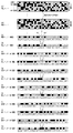
異常ノズルと検出するために、まず当該インクジェット記録装置の色材インク用の各記録ヘッド21−1,21−3,21−4,21−5を用いて、図7に示すような階段状の記録パターンを実際に記録媒体24に印字する(図6ステップ100)。
【0050】
階段パターンは、図7に示すように、たとえば8ノズルおきに各ノズルから、連続もしくは非連続に色材インクを吐出させることで短い直線を階段状に印字したものである。異常ノズルが存在しない場合は、図7(a)に示すように、階段状のパターンを完全に印字することができる。図7(b)は、18番目のノズルN18に不吐出が発生し、28番目のノズルN28および30番目のノズルN30に不良が発生しているときの階段パターンを示すものである。不吐出ノズルまたは不良ノズルによって記録された直線は、一部または全てに欠けがあるので、これを容易に識別することができる。
【0051】
このような印字物(階段チャート)を、本装置に搭載されている不図示の読取センサを用いて読み取り走査し、該読み取ったデータに認識処理などを実行させることにより、何番目のノズルが異常であるかを検出する(図6ステップ101)。なお、読取センサを用いずに目視判断して、不吐出/不良ノズルデータを作成し、これをプリンタ装置に入力してもよい。
【0052】
このようにして検出された各色材記録ヘッド毎の不吐出/不良ノズルに基づいて異常ノズルデータを作成する。この異常ノズルデータは、複数のノズルのうち不吐出/不良ノズルを特定するデータであり、作成された異常ノズルデータは色材記録ヘッド毎に装置内のメモリに記憶される。図7の場合は、ノズルN18、N28、N30が異常ノズルとして、異常ノズルデータが作成されることになる。
【0053】
上記異常ノズルの検出の結果(ステップ101)、異常ノズルが検出されない場合は、通常の印字出力制御を実行する(図6ステップ102)。
【0054】
しかし、上記異常ノズルの検出の結果、異常ノズルが検出された場合は、まず作成した異常ノズルデータに基づいて色材記録ヘッド用のノズル駆動データとプリント性向上インクヘッドのノズル駆動データから異常ノズルに対応する走査ラインのデータを削除、すなわち不吐出のデータ(“0”)とする(ステップ103)。なお、この際、プリントデータを不吐出(オフ)としてもよいし、電気的にプリントヘッドの不吐出ノズルヘの信号をマスキングするようにしてもよい。
【0055】
つぎに、色材記録ヘッドの異常ノズルデータに基づいて不吐出改善データを付加することにより、プリント性向上インクヘッド用のノズル駆動データの異常ノズルに対応する走査ラインおよび該走査ラインに隣接する走査ラインのデータを補正変更する(ステップ104)。具体的には、例えば、色材記録ヘッドの異常ノズルに対応する走査ラインの前後のラインのノズル駆動データに基づいて、プリント性向上インクヘッド用のノズル駆動データの異常ノズルに対応する走査ラインあるいは該走査ラインに隣接する走査ラインのデータを補正変更するようにしている。
【0056】
そして、このように補正変更した各ノズル駆動データに基づいて各記録ヘッドを駆動することにより、記録媒体24上に画像を形成する(ステップ105)。
【0057】
以下、上記したステップ103及び104の処理について、より具体的に説明する。
【0058】
(第1の実施形態)
以下の実施形態では、例えば、黒ヘッドのノズル駆動データに基づいてプリント性向上インクのノズル駆動データを作成する。なお、例えば、黒ヘッドがよれが大きいなどの状態のときには、プリント性向上インクを増大させるなど、黒ヘッドの印字状態に応じてプリント性向上インク滴の量を増減することで、黒ヘッドによるドットとプリント性向上インクによるドットとをほぼ確実に近接して印字することができ、これによりプリント性向上インクと黒インクとを確実に接触させることができる。
【0059】
この第1の実施形態においては、黒ヘッドのノズルによる記録ドットとプリント性向上インクによる記録ドットの位置が一致しているとする。
【0060】
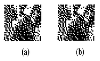
図8(a)は異常ノズルが無い場合の黒インクのプリントデータに対応する記録画像であり、図8(b)はこれに対応するプリント性向上インクのプリントデータである。この場合は、異常ノズルが無いので、両者のプリントデータは一致している。
【0061】
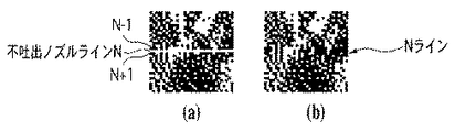
図9(a)は不吐出ノズルがある場合の黒インクのプリントデータであり、不吐出ノズルライン(白すじ)が形成されている。図9(b)はプリント性向上インクの補正処理後のプリントデータである。この実施形態では、黒ヘッドの異常ノズル情報にしたがってプリント性向上インクのプリントデータを補正する。具体的には、黒ヘッドのN番目のノズルが不吐出ノズルとして検知された場合、プリント性向上ヘッドのN番目のノズルのプリントデータは次のようにして作成される。すなわち、黒ヘッドのN番目のノズルの両隣りのノズル(N−1番目およびN+1番目)のプリントデータを参照し、N−1ラインおよびN+1ラインの双方に吐出有りのプリントデータが存在するドットのみを吐出有りとする。なお、この場合、N番目のノズルのプリントデータについて、補正処理前に吐出ありであったとしても、黒ヘッドのN−1ラインおよびN+1ラインの双方に吐出有りのプリントデータが存在しない場合は、吐出なしに変更される。
【0062】
図10(a)は2パスでマルチパス印字する際に不吐出ノズルがある場合の1パス目の黒ヘッドのプリントデータ、図10(b)は同2パス目の黒ヘッドのプリントデータであり、不吐出ノズルラインが形成されている。図10(c)は補正処理後のプリント性向上インクの1パス目のプリントデータであり、不吐出ノズルラインに対応するラインのデータが、1パス目の黒ヘッドの不吐出ノズルラインの前後のラインの印字データに基づき形成され、追加されている。図10(d)は補正処理後のプリント性向上インクの2パス目のプリントデータであり、不吐出ノズルラインに対応するラインのデータが、2パス目の黒ヘッドの不吐出ノズルラインの前後のラインの印字データに基づき形成され、追加されている。
【0063】
すなわち、2パスで印字する場合には、1パス目に不吐出ノズルによって生じた画像の欠けも、2パス目には該欠けラインを相互補完する他のノズルで印字することが可能であるが、2パス目に通過するノズルもまた同様に不吐出ノズルであったときには、上記画像の欠けを解消することは困難である。したがって、マルチパス印字の場合も、図10に示すような処理を行うことで、不吐出ノズルラインの選択されたドットに対し故意にプリント性向上インクを付与し、これにより不吐出ノズルラインの前後から色材インクのドットを呼び水式に太らせ、白スジを目立たないようにしている。
【0064】
なお、マルチパス印字の場合は、色材ドットおよびプリント性向上インクを接触させようとするドットに対して両者の着弾の時間差が大きくなると、呼び水式による効果が削減されるので、色材ドットおよびプリント性向上インクを接触させようとするドットに関しては、色材ドットおよびプリント性向上インクが同一パスで吐出されるようにすることが必要である。
【0065】
(第2の実施形態)
つぎに、図11および図12を用いてこの発明の第2の実施形態について説明する。
【0066】
この第2の実施形態では、600dpiの解像度で、各インク滴が8.5±0.5p1で吐出される記録ヘッド21を用いた。
【0067】
色材を含有する色材インクおよびプリント性向上インクの組成は以下の通りである。
【0068】
(イエローインク)
・グリセリン 5.0重量%
・チオジグリコール 5.0重量%
・尿素 5.0重量%
・イソプロピルアルコール 4.0重量%
・アセチレノールEH(川研ケミカル) 1.0重量%
・染料C.I.ダイレクトイエロー142 2.0重量%
・水 78.0重量%
(マゼンタインク)
・グリセリン 5.0重量%
・チオジグリコール 5.0重量%
・尿素 5.0重量%
・イソプロピルアルコール 4.0重量%
・アセチレノールEH(川研ケミカル) 1.0重量%
・染料C.I.アシッドレッド289 2.5重量%
・水 77.5重量%
(シアンインク)
・グリセリン 5.0重量%
・チオジグリコール 5.0重量%
・尿素 5.0重量%
・イソプロピルアルコール 4.0重量%
・アセチレノールEH(川研ケミカル) 1.0重量%
・染料C.I.ダイレクトブルー199 2.5重量%
・水 77.5重量%
(黒インク)
・グリセリン 5.0重量%
・チオジグリコール 5.0重量%
・尿素 5.0重量%
・イソプロピルアルコール 4.0重量%
・染料フードプラック2 3.0重量%
・水 78.0重量%
(プリント性向上インク)
・ポリアリルアミン塩酸塩 5.0重量%
・塩化ベンザルコニウム 1.0重量%
・ジエチレングリコール 10.0重量%
・アセチレノールEH(川研ケミカル) 1.0重量%
・水 83.0重量%
また、記録媒体としては電子写真・インクジェット共用紙(PB・PAPER:キヤノン株式会社製)を用いた。
【0069】
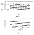
また、この第2の実施形態においては、図11に示すように、プリント性向上インクによるドットマトリックスは、色材インクによるドットマトリックスから1/k画素分(1/4画素あるいは1/2画素など)ずらせて印字を行うようにしている。図11の場合は、プリント性向上インクによる各ドットは、対応する色材インクのドットから図面上右下方向に1/4画素だけずれて印字される。これは、例えば、色材ヘッドとプリント性向上インクヘッドを所要量だけずらしてキャリッジに固定することなどで容易に実現することができる。
【0070】
そしてこのように、プリント性向上インクのドット位置を色材インクのドットからずらせるようにすれば、より効果的に色材ドットを不吐出ノズルのドットの部位に滲ませたりあるいは太らせることが可能になる。
【0071】
以下、図12を参照して、第2の実施形態による先の図6のステップ103および104での具体的処理内容について説明する。
【0072】
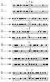
図12(a)は、前述したように、32個のノズル(インク吐出口)を有するプリント性向上インク用の記録ヘッドによる主走査方向に6個(画素)分(M番目〜M+5番目)の2値化された補正処理前の画像データを模式的に示すものである。黒の塗りつぶしが画像データあり(“1”)のドットであり、白のドットが画像データなし(“0”)に対応する。
【0073】
図12(b)は、同様に32個のノズルを有する色材インク用の記録ヘッドによる主走査方向についての6個分(M番目〜M+5番目)の同様の画像データを模式的に示すものである。この場合は、色材ヘッドおよびプリント性向上ヘッドは同一の画像データ(ノズル駆動データ)が付与されるものとする。
【0074】
図12(b)に示すように、色材記録ヘッドのN個目のノズル(この場合N=16)が不吐出ノズルであるとする。
【0075】
色材記録ヘッドのN個目のノズル(この場合N=16)が不吐出ノズルであるので、図12(c)、(e)、(g)、(i)、(k)、(m)に示すように、色材記録ヘッドのM番目〜M+5番目の画像データに関しては、元の画素データの“0”,“1”に関係なくN個目の印字データを“0”(不吐出)に補正する。
【0076】
一方、プリント性向上インク用の記録ヘッドのM番目〜M+5番目の画像データに関しては、元の画素データの“0”,“1”に関係なく、色材記録ヘッドの同じ番目の印字データ中のN−1個目およびN+1個目の印字データの“0”,“1”を参照し、これらN−1個目およびN+1個目の印字データに基づいて、“0”(不吐出)、“1”(吐出)を決定する。この実施形態では、色材記録ヘッドのN−1個目およびN+1個目の印字データの何れかに“1”があった場合に、プリント性向上インクのN個目の印字データを“1”としている。
【0077】
すなわち、図12(c)に示すように、色材ヘッドのM番目の画像データは、N−1個目およびN+1個目に画像データがない。よって、図12(d)に示すように、プリント性向上インクヘッドのM番目の画像データについては、N個目のプリントデータは“0”とする。
【0078】
つぎに、図12(e)に示すように、色材ヘッドのM+1番目の画像データは、N−1個目およびN+1個目に画像データがない。よって、図12(f)に示すように、プリント性向上インクヘッドのM+1番目の画像データについては、N個目のプリントデータは“0”とする。
【0079】
つぎに、図12(g)に示すように、色材ヘッドのM+2番目の画像データは、N−1個目に画像データがある。よって、図12(h)に示すように、プリント性向上インクヘッドのM+2番目の画像データについては、N個目のプリントデータは“1”に補正する。
【0080】
つぎに、図12(i)に示すように、色材ヘッドのM+3番目の画像データは、N+1個目に画像データがある。よって、図12(j)に示すように、プリント性向上インクヘッドのM+3番目の画像データについては、N個目のプリントデータは“1”に補正する。
【0081】
つぎに、図12(k)に示すように、色材ヘッドのM+4番目の画像データは、N−1個目に画像データがある。よって、図12(l)に示すように、プリント性向上インクヘッドのM+4番目の画像データについては、N個目のプリントデータは“1”に補正する。
【0082】
つぎに、図12(m)に示すように、色材ヘッドのM+5番目の画像データは、N−1個目、N+1個目に画像データがある。よって、図12(n)に示すように、プリント性向上インクヘッドのM+5番目の画像データについては、N個目のプリントデータは“1”に補正する。
【0083】
以下、画像データ全体にわたって同様の処理を行い、色材インクおよびプリント性向上インクによる印字を行う。
【0084】
図11は色材ヘッドのN個目のノズルに不吐出が発生した場合の、第2の実施形態による補正処理後の色材ドットのプリントデータおよびプリント性向上インクのプリントデータによる記録ドットを示すものである。
【0085】
この図からも判るように、不吐出が発生したNラインでは、色材ヘッドのN−1ラインおよびN+1ラインの印字データに応じて、プリント性向上インクによるドットが部分的に追加されている。
【0086】
(第3の実施形態)
つぎに、図13および図14を用いてこの発明の第3の実施形態について説明する。
【0087】
この第3の実施形態では、不吐出が発生したNライン目では、色材ヘッドのN−1ラインおよびN+1ラインの印字データに応じてプリント性向上インクによる記録ドットを形成する点は先の第2の実施形態と同様である。この第3の実施形態では、色材ヘッドのN−1ラインおよびN+1ラインのM番目の印字データに応じて、プリント性向上インクによるNラインのM−1番目、M番目およびM+1番目の記録ドットを形成する。すなわち、色材記録ヘッドのN−1ラインのM番目またはN+1ラインのM番目に“1”があった場合に、プリント性向上インクのNラインのM−1番目、M番目およびM+1番目の印字データを“1”としている。
【0088】
この実施形態においても、先の第2の実施形態と同様、600dpiの解像度で、各インク滴が8.5±0.5p1で吐出される記録ヘッド21を用いた。また、色材を含有する色材インク、プリント性向上インクの組成および記録媒体は先の第2の実施形態と同様のものを用いた。
【0089】
また、図13に示すように、プリント性向上インクによる各ドットは、第2の実施形態と同様、対応する色材インク(黒インク)のドットから図面上右下方向に1/4画素だけずれて印字されるようにした。
【0090】
色材記録ヘッドのN個目のノズル(この場合N=16)が不吐出ノズルであるので、図14(a)、(c)、(e)、(g)、(i)、(k)に示すように、色材記録ヘッドのM番目〜M+5番目の画像データに関しては、元の画素データの“0”,“1”に関係なくN個目の印字データを“0”に補正する。
【0091】
つぎに、プリント性向上インク用の記録ヘッドのM番目〜M+5番目の画像データについて説明する。
【0092】
図14(a)に示すように、色材ヘッドのM番目の画像データは、N−1個目およびN+1個目に画像データがない。よって、図14(b)に示すように、プリント性向上インクヘッドのM番目の画像データについては、N個目のプリントデータは“0”とする。
【0093】
つぎに、図14(c)に示すように、色材ヘッドのM+1番目の画像データは、N−1個目およびN+1個目に画像データがない。よって、図14(d)に示すように、プリント性向上インクヘッドのM+1番目の画像データについては、N個目のプリントデータは“0”とする。
【0094】
つぎに、図12(e)に示すように、色材ヘッドのM+2番目の画像データは、N−1個目に画像データがある。よって、図12(f)に示すように、プリント性向上インクヘッドのM+1番目、M+2番目、M+3番目の画像データについては、N個目のプリントデータを“1”に補正する。
【0095】
つぎに、図12(g)に示すように、色材ヘッドのM+3番目の画像データは、N+1個目に画像データがある。よって、図12(h)に示すように、プリント性向上インクヘッドのM+2番目、M+3番目、M+4番目の画像データについては、N個目のプリントデータを“1”に補正する。
【0096】
つぎに、図12(i)に示すように、色材ヘッドのM+4番目の画像データは、N−1個目に画像データがある。よって、図12(j)に示すように、プリント性向上インクヘッドのM+3番目、M+4番目、M+5番目の画像データについては、N個目のプリントデータを“1”に補正する。
【0097】
つぎに、図12(k)に示すように、色材ヘッドのM+5番目の画像データは、N−1個目、N+1個目に画像データがある。よって、図12(l)に示すように、プリント性向上インクヘッドのM+4番目、M+5番目、M+6番目の画像データについては、N個目のプリントデータを“1”に補正する。
【0098】
以下、画像データ全体にわたって同様の処理を行い、色材インクおよびプリント性向上インクによる印字を行う。
【0099】
図13は色材ヘッドのN個目のノズルに不吐出が発生した場合の、第3の実施形態による補正処理後の色材ドットのプリントデータおよびプリント性向上インクのプリントデータによる記録ドットを示すものである。
【0100】
この図からも判るように、不吐出が発生したNラインでは、色材ヘッドのN−1ラインおよびN+1ラインの印字データに応じて、プリント性向上インクによるドットが先の第2の実施形態よりも多く追加されている。
【0101】
(第4の実施形態)
つぎに、図15および図16を用いてこの発明の第4の実施形態について説明する。
【0102】
この第4の実施形態では、色材ヘッドのN−1ラインおよびN+1ラインの印字データに応じて不吐出が発生したNライン目のプリント性向上インクによる記録ドットを形成する点は先の第2または第3の実施形態と同様である。この第4の実施形態では、色材記録ヘッドのN−1個目およびN+1個目の印字データの何れかに“1”があった場合に、プリント性向上インクのN個目の印字データを“1”としている。さらに、この第4の実施形態では、色材記録ヘッドのN−1個目の印字データに“1”があった場合に、プリント性向上インクのN−1個目の印字データを“0”とするとともに、色材記録ヘッドのN+1個目の印字データに“1”があった場合に、プリント性向上インクのN+1個目の印字データを“0”としている。
【0103】
この実施形態においても、先の第2、第3の実施形態と同様、600dpiの解像度で、各インク滴が8.5±0.5p1で吐出される記録ヘッド21を用いた。また、色材を含有する色材インク、プリント性向上インクの組成および記録媒体は先の第2、第3の実施形態と同様のものを用いた。また、図15に示すように、プリント性向上インクによる各ドットは、第2の実施形態と同様、対応する色材インクのドットから図面上右下方向に1/4画素だけずれて印字されるようにした。
【0104】
この場合も。色材記録ヘッドのN個目のノズル(この場合N=16)が不吐出ノズルであるので、図16(a)(c)、(e)、(g)、(i)、(k)に示すように、色材記録ヘッドのM番目〜M+5番目の画像データに関しては、元の画素データの“0”,“1”に関係なくN個目の印字データを“0”(不吐出)に補正する。
【0105】
つぎに、プリント性向上インク用の記録ヘッドのM番目〜M+5番目の画像データについて説明する。
【0106】
図16(a)に示すように、色材ヘッドのM番目の画像データは、N−1個目およびN+1個目に画像データがない。よって、図16(b)に示すように、プリント性向上インクヘッドのM番目の画像データについては、N個目のプリントデータは“0”とする。また、プリント性向上インクヘッドのN−1個目、N+1個目のプリントデータは“0”のままとする。
【0107】
つぎに、図16(c)に示すように、色材ヘッドのM+1番目の画像データは、N−1個目およびN+1個目に画像データがない。よって、図16(d)に示すように、プリント性向上インクヘッドのM+1番目の画像データについては、N個目のプリントデータは“0”とする。また、プリント性向上インクヘッドのN−1個目、N+1個目のプリントデータは“0”のままとする。
【0108】
つぎに、図16(e)に示すように、色材ヘッドのM+2番目の画像データは、N−1個目に画像データがある。よって、図16(f)に示すように、プリント性向上インクヘッドのM+2番目の画像データについては、N個目のプリントデータは“1”に補正する。さらに、プリント性向上インクヘッドのN−1個目のプリントデータを“0”に補正する。
【0109】
つぎに、図16(g)に示すように、色材ヘッドのM+3番目の画像データは、N+1個目に画像データがある。よって、図16(h)に示すように、プリント性向上インクヘッドのM+3番目の画像データについては、N個目のプリントデータは“1”に補正する。さらに、プリント性向上インクヘッドのN+1個目のプリントデータを“0”に補正する。
【0110】
つぎに、図16(i)に示すように、色材ヘッドのM+4番目の画像データは、N−1個目に画像データがある。よって、図16(j)に示すように、プリント性向上インクヘッドのM+4番目の画像データについては、N個目のプリントデータは“1”に補正する。さらに、プリント性向上インクヘッドのN−1個目のプリントデータを“0”に補正する。
【0111】
つぎに、図16(k)に示すように、色材ヘッドのM+5番目の画像データは、N−1個目、N+1個目に画像データがある。よって、図16(l)に示すように、プリント性向上インクヘッドのM+5番目の画像データについては、N個目のプリントデータは“1”に補正する。さらに、プリント性向上インクヘッドのN−1個目およびN+1個目のプリントデータを“0”に補正する。
【0112】
以下、画像データ全体にわたって同様の処理を行い、色材インクおよびプリント性向上インクによる印字を行う。
【0113】
図15は色材ヘッドのN個目のノズルに不吐出が発生した場合の、第4の実施形態による補正処理後の色材ドットのプリントデータおよびプリント性向上インクのプリントデータによる記録ドットを示すものである。
【0114】
この図からも判るように、不吐出が発生したNラインでは、色材ヘッドのN−1ラインおよびN+1ラインの印字データに応じて、プリント性向上インクによるドットが部分的に追加されている。また、色材ヘッドのN−1ラインおよびN+1ラインの印字データに応じて、プリント性向上インクのN−1ラインおよびN+1ラインの記録ドットが削除されている。
【0115】
(第5の実施形態)
つぎに、図17および図18を用いてこの発明の第5の実施形態について説明する。
【0116】
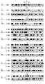
この第5の実施形態では、N個目のノズルに異常が発生したとすると、色材記録ヘッドのM番目でかつN−1個目の印字データに“1”があった場合には、プリント性向上インクのN−1個目でかつM−1番目の印字データ、N−1個目でかつM番目の印字データ、N−1個目でかつM+1番目の印字データ、N個目でかつM−1番目の印字データ、N個目でかつM番目の印字データおよびN個目でかつM+1番目の印字データを“1”に補正する。また、色材記録ヘッドのM番目でかつN+1個目の印字データに“1”があった場合には、プリント性向上インクのN個目でかつM−1番目の印字データ、N個目でかつM番目の印字データ、N個目でかつM+1番目の印字データ、N+1個目でかつM−1番目の印字データ、N+1個目でかつM番目の印字データおよびN+1個目でかつM+1番目の印字データを“1”に補正する。
【0117】
この実施形態においても、先の第2〜第4の実施形態と同様、600dpiの解像度で、各インク滴が8.5±0.5p1で吐出される記録ヘッド21を用いた。また、色材を含有する色材インク、プリント性向上インクの組成および記録媒体は先の第2〜第4の実施形態と同様のものを用いた。また、図17に示すように、プリント性向上インクによる各ドットは、第2の実施形態と同様、対応する色材インクのドットから図面上右下方向に1/4画素だけずれて印字されるようにした。
【0118】
この場合も。色材記録ヘッドのN個目のノズル(この場合N=16)が不吐出ノズルであるので、図18(a)(c)、(e)、(g)、(i)、(k)に示すように、色材記録ヘッドのM番目〜M+5番目の画像データに関しては、元の画素データの“0”,“1”に関係なくN個目の印字データを“0”(不吐出)に補正する。
【0119】
つぎに、プリント性向上インク用の記録ヘッドのM番目〜M+5番目の画像データについて説明する。
【0120】
図18(a)に示すように、色材ヘッドのM番目の画像データは、N−1個目およびN+1個目に画像データがない。よって、図18(b)に示すように、プリント性向上インクヘッドのM番目の画像データについては、N個目のプリントデータは“0”とする。
【0121】
つぎに、図18(c)に示すように、色材ヘッドのM+1番目の画像データは、N−1個目およびN+1個目に画像データがない。よって、図18(d)に示すように、プリント性向上インクヘッドのM+1番目の画像データについては、N個目のプリントデータは“0”とする。
【0122】
つぎに、図18(e)に示すように、色材ヘッドのM+2番目の画像データは、N−1個目に画像データがある。よって、図18(f)に示すように、プリント性向上インクヘッドのM+1番目、M+2番目、M+3番目で、N−1個目、N個目の6つの画素の画像データについては、これを“1”に補正する。
【0123】
つぎに、図18(g)に示すように、色材ヘッドのM+3番目の画像データは、N+1個目に画像データがある。よって、図18(h)に示すように、プリント性向上インクヘッドのM+2番目、M+3番目、M+4番目で、N個目、N+1個目の6つの画素の画像データについては、これを“1”に補正する。
【0124】
つぎに、図18(i)に示すように、色材ヘッドのM+4番目の画像データは、N−1個目に画像データがある。よって、図18(j)に示すように、プリント性向上インクヘッドのM+3番目、M+4番目、M+5番目で、N−1個目、N個目の6つの画素の画像データについては、これを“1”に補正する。
【0125】
つぎに、図18(k)に示すように、色材ヘッドのM+5番目の画像データは、N−1個目、N+1個目に画像データがある。よって、図18(l)に示すように、プリント性向上インクヘッドのM+4番目、M+5番目、M+6番目で、N−1個目、N個目、N+1個目の9つの画素の画像データについては、これを“1”に補正する。
【0126】
以下、画像データ全体にわたって同様の処理を行い、色材インクおよびプリント性向上インクによる印字を行う。
【0127】
図17は色材ヘッドのN個目のノズルに不吐出が発生した場合の、第5の実施形態による補正処理後の色材ドットのプリントデータおよびプリント性向上インクのプリントデータによる記録ドットを示すものである。
【0128】
この図からも判るように、プリント性向上ヘッドのNライン、その前後のN−1ライン,N+1ラインでは、色材ヘッドのN−1ラインおよびN+1ラインの印字データに応じて、記録ドットが多く追加されている。
【0129】
(第6の実施形態)
つぎに、3種類の異なる記録媒体を用いて、第2〜第4の実施形態の手法を評価してみた。白スジの目立たない度合いを最良、良、普通の3段階として評価した。
【0130】
PB−PAPERを用い第2の実施形態の手法を用いた…良
PB−PAPERを用い第3の実施形態の手法を用いた…最良
PB−PAPERを用い第4の実施形態の手法を用いた…最良
PB−PAPERを用い第5の実施形態の手法を用いた…最良
HR−101を用い第2の実施形態の手法を用いた…良
HR−101を用い第3の実施形態の手法を用いた…良
HR−101を用い第4の実施形態の手法を用いた…最良
HR−101を用い第5の実施形態の手法を用いた…最良
GP−101を用い第2の実施形態の手法を用いた…普通
GP−101を用い第3の実施形態の手法を用いた…普通
GP−101を用い第4の実施形態の手法を用いた…良
GP−101を用い第5の実施形態の手法を用いた…良
上記の結果によれば、記録媒体の種類に応じてプリント性向上インクの付与形態を異ならせれば、各記録媒体に最適な白すじ防止をなし得ることが判る。
【0131】
なお、プリント性向上インクによる印字を行った後、別の走査時に色材インクによる不吐出ノズルを有する色材ヘッドでの印字を行った。このときの記録媒体上でのプリント性向上インクの着弾時間と、色材インクの着弾時間の差は2secであった。この場合、残念ながら、先の実施形態で見られたような効果はなく、白スジによる画品位の劣化は改善されなかった。
【0132】
(第7の実施形態)
この第7の実施形態では、プリント性向上インクとして下記の組成を持つクリアインクを用い、先の第4実施形態による手法で不吐出ノズルラインNにプリント性向上インクによる記録ドットを形成した。また、プリント性向上インクのN番目のノズル以外の印字データは0としてプリント動作を行う。
【0133】
(クリアインク)
・グリセリン 5.0重量%
・チオジグリコール 5.0重量%
・尿素 5.0重量%
・イソプロピルアルコール 4.0重量%
・アセチレノールEH(川研ケミカル) 1.0重量%
・水 80.0重量%
この第7の実施形態による手法でも、白すじを減少することができた。
【0134】
(第8の実施形態)
この第8の実施形態では、先の第2実施形態などと同様の色材インク、プリント性向上インク、記録媒体を用いる。ここで、この第8の実施形態においては、黒インクに対しては、図17に示したように、不吐出、不良ノズルの近傍部分と、不吐出、不良ノズルのない通常の画像の部分にプリント性向上インクを付与し、シアン、マゼンタ、イエローインクに対しては、図19に示すように、不吐出、不良ノズルの近傍部分のみへプリント性向上インクを付与し、通常の画像の部分にはプリント性向上インクを付与しないようにしている。この実施形態においても、スジの減少した良好な記録画像を得ることができた。
【0135】
(変形例)
なお、上記実施形態では、N番目のノズルに異常が発生している場合、N−1番目のノズルおよびN+1番目のノズルに関する印字データに基づいて、これらノズルの記録ドットに連接されるようにプリント性向上インクの印字情報を作成したが、他に例えばN−2番目、N−1番目、N+1番目およびN+2番目のノズルの印字データに基づいてプリント性向上インクの印字情報を作成するようにしてもよい。場合によっては、一定の密度で均一にプリント性向上インクを印字してもよい。要は、不吐出ノズルラインに近接する色材ドットに対しより多くのプリント性向上インクがその近傍に印字されることで、本発明は達成される。
【0136】
なお、本発明では、プリント性向上インクは、無色透明でもよいが、着色してあってもよい。また、プリント性向上インクは、単に色材を含まない組成のクリアインクでもよい。また、場合によっては、インクノズルから吐出することの可能な液体であればよい。
【0137】
上述したように、色材ドットとプリント性向上インクとが接触すると、瞬時に色材が記録媒体上で凝集する。したがって、色材ドットと隣接するプリント性向上インクのドットは、十分時間間隔を置かれて印字されても、充分な効果は望めない、よってインクが紙面に十二分に吸収される以前に、色材インクとプリント性向上インクとを接触させることが好ましい。さらに、本発明においては、プリント性向上インクと色材ドットが記録媒体上で積極的に混合することが望ましいと考えられるので、これら接触するまでの時間間隔は、さらに短いことが望まれる。
【0138】
また印字順序についても、先にプリント性向上インクを印字したのちに色材インクを印字してもよいし、先に色材インクを印字した後にプリント性向上インクを印字してもよい。いずれにしても記録媒体に、色材インクおよびプリント性向上インクが浸透しきってしまった後あるいは乾燥してしまった後では、上記の時間間隔は空きすぎである。
【0139】
上記実施形態では、色材ドットとプリント性向上インクドットのドットマトリクスの大きさを変えないようにしているが、色材ドットのマトリクスと、プリント性向上インクのマトリクスの大きさを異ならせてもよい。すなわち色材ドットの出力解像度を維持し、プリント性向上インクの出力解像度を低下させることで、プリント性向上インクのデータ処理および装置上のプリント性向上インクにかかるコストを低減することができる。
【0140】
本発明では、プリント性向上インクのプリントデータは、単純な画像処理を用いて作成することができるので、処理の高速化が可能である。尚、多少のコストアップを伴うが、各色毎に複数の濃淡インク、大小ドットを使用してもよい。本発明では、その場合においても、より高次の階調を記録媒体上に再現することができる。
【0141】
本発明は、少なくとも1種類の色材インクとプリント性向上インクの組み合わせで実施できるが、2種類以上の色材インク、2種類以上のプリント性向上インクを用意してもよい。その場合においては、前述したように、プリント性向上インクもしくは色材インクがぬれている間に色材インクもしくはプリント性向上インクを所望の着弾位置に着弾させればよく、また、色材インクは、いずれの色相を有してもよい。また、いずれかの色材インクにおいてのみ、本発明を適応する実施形態であってもかまわない。本発明においては、上述した各インクに対して最も有効なものは、上述した膜沸騰方式を実行するものである。
【0142】
(その他)
上述した本発明の実施形態として、階段状の記録パターンを実際に記録媒体記録し、その結果に基づいて不吐出ノズルや不良ノズルを検出する構成を例に挙げて説明したが、本発明は上述の検出構成を特徴とするものではなく、他の手法も適宜採用することができる。また、本発明は、異常が発生したノズルを検出する構成を有していなくても、異常が発生したノズルを特定できれば、目的を達成することができる。例えば、ユーザが目視によって判断した結果を、プリント装置本体に直接入力したり、プリント装置に接続されるホスト装置のドライバを介して入力することにより、不良ノズルや不吐出ノズルを特定することが可能である。また、記録ヘッドに情報を書込み可能なメモリ等の記憶手段を設けた構成においては、ノズル毎の情報や、不吐出/不良ノズルの情報を記憶手段に記憶させておくことで、プリント装置本体がその情報を読み取って不吐出/不良ノズルを特定することができる。なお、記録ヘッド設けた記憶手段に情報を記憶させる時期に関しては、出荷時に初期状態を記憶させておく構成や、さらにユーザの使用履歴に従って記憶させる構成など、いずれの場合であってもよい。 なお、本発明は、特にインクジェット記録方式の中でも、インク吐出を行わせるために利用されるエネルギとして熱エネルギを発生する手段(例えば電気熱変換体やレーザ光等)を備え、前記熱エネルギによりインクの状態変化を生起させる方式の記録ヘッド、記録装置において優れた効果をもたらすものである。かかる方式によれば記録の高密度化,高精細化が達成できるからである。
【0143】
その代表的な構成や原理については、例えば、米国特許第4723129号明細書,同第4740796号明細書に開示されている基本的な原理を用いて行うものが好ましい。この方式は所謂オンデマンド型,コンティニュアス型のいずれにも適用可能であるが、特に、オンデマンド型の場合には、液体(インク)が保持されているシートや液路に対応して配置されている電気熱変換体に、記録情報に対応していて核沸騰を越える急速な温度上昇を与える少なくとも1つの駆動信号を印加することによって、電気熱変換体に熱エネルギを発生せしめ、記録ヘッドの熱作用面に膜沸騰を生じさせて、結果的にこの駆動信号に一対一で対応した液体(インク)内の気泡を形成できるので有効である。この気泡の成長,収縮により吐出用開口を介して液体(インク)を吐出させて、少なくとも1つの滴を形成する。この駆動信号をパルス形状とすると、即時適切に気泡の成長収縮が行われるので、特に応答性に優れた液体(インク)の吐出が達成でき、より好ましい。このパルス形状の駆動信号としては、米国特許第4463359号明細書,同第4345262号明細書に記載されているようなものが適している。なお、上記熱作用面の温度上昇率に関する発明の米国特許第4313124号明細書に記載されている条件を採用すると、さらに優れた記録を行うことができる。
【0144】
記録ヘッドの構成としては、上述の各明細書に開示されているような吐出口,液路,電気熱変換体の組合せ構成(直線状液流路または直角液流路)の他に熱作用部が屈曲する領域に配置されている構成を開示する米国特許第4558333号明細書,米国特許第4459600号明細書を用いた構成も本発明に含まれるものである。加えて、複数の電気熱変換体に対して、共通するスリットを電気熱変換体の吐出部とする構成を開示する特開昭59−123670号公報や熱エネルギの圧力波を吸収する開孔を吐出部に対応させる構成を開示する特開昭59−138461号公報に基いた構成としても本発明の効果は有効である。すなわち、記録ヘッドの形態がどのようなものであっても、本発明によれば記録を確実に効率よく行うことができるようになるからである。
【0145】
さらに、記録装置が記録できる記録媒体の最大幅に対応した長さを有するフルラインタイプの記録ヘッドに対しても本発明は有効に適用できる。そのような記録ヘッドとしては、複数記録ヘッドの組合せによってその長さを満たす構成や、一体的に形成された1個の記録ヘッドとしての構成のいずれでもよい。
【0146】
加えて、上例のようなシリアルタイプのものでも、装置本体に固定された記録ヘッド、あるいは装置本体に装着されることで装置本体との電気的な接続や装置本体からのインクの供給が可能になる交換自在のチップタイプの記録ヘッド、あるいは記録ヘッド自体に一体的にインクタンクが設けられたカートリッジタイプの記録ヘッドを用いた場合にも本発明は有効である。
【0147】
また、本発明の記録装置の構成として、記録ヘッドの吐出回復手段、予備的な補助手段等を付加することは本発明の効果を一層安定できるので、好ましいものである。これらを具体的に挙げれば、記録ヘッドに対してのキャッピング手段、クリーニング手段、加圧或は吸引手段、電気熱変換体或はこれとは別の加熱素子或はこれらの組み合わせを用いて加熱を行う予備加熱手段、記録とは別の吐出を行なう予備吐出手段を挙げることができる。
【0148】
また、搭載される記録ヘッドの種類ないし個数についても、例えば単色のインクに対応して1個のみが設けられたものの他、記録色や濃度を異にする複数のインクに対応して複数個数設けられるものであってもよい。すなわち、例えば記録装置の記録モードとしては黒色等の主流色のみの記録モードだけではなく、記録ヘッドを一体的に構成するか複数個の組み合わせによるかいずれでもよいが、異なる色の複色カラー、または混色によるフルカラーの各記録モードの少なくとも一つを備えた装置にも本発明は極めて有効である。
【0149】
さらに加えて、本発明インクジェット記録装置の形態としては、コンピュータ等の情報処理機器の画像出力端末として用いられるものの他、リーダ等と組合せた複写装置、さらには送受信機能を有するファクシミリ装置の形態を採るもの等であってもよい。
【0150】
【発明の効果】
以上説明したように本発明によれば、不吐出、不良ノズルの位置情報を参照し、不吐出、不良ノズルの位置およびその近傍にプリント性向上インクによるインクドットを付与するようにしたので、不吐出ノズルラインの前後から色材インクのドットが呼び水式に太らせられて白スジが目立たないなる。
【0151】
したがって、本発明では、色材インクヘッドに不吐出、不良ノズルが発生した場合でも、簡単な処理で、記録画像中の白スジの発生を大幅に低減することができ、高品位な画像を提供することができる。また、不吐出ノズルが発生したインクヘッドも交換することなく長期にわたって使用することができ、エコロジーの観点からも好ましい。
【図面の簡単な説明】
【図1】本発明の一実施形態に係るインクジェット記録装置の概略構成を示す平面図である。
【図2】インクジェット記録ヘッドの吐出口の配列状態を示す概念図である。
【図3】インクジェット記録ヘッドの構造を示す分解斜視図である。
【図4】インクジェット記録装置の制御系の構成例を示すブロック図である。
【図5】色材インクとプリント性向上インクの記録媒体上での状態を示した図である。
【図6】この発明にかかるインクジェット記録方法の動作例を示すフローチャートである。
【図7】不吐出、不良ノズルを検知するための階段チャートの一例を示す図である。
【図8】不吐出ノズルがない場合の色材インクおよびプリント性向上インクのプリントデータを示す概念図である。
【図9】不吐出ノズルがある場合の色材インクおよびプリント性向上インクの補正処理後のプリントデータを示す概念図である。
【図10】不吐出ノズルがある場合でマルチパス印字を行う場合の色材インクおよびプリント性向上インクの補正処理後のプリントデータを示す概念図である。
【図11】この発明の第2の実施形態による補正処理後の色材インクおよびプリント性向上インクのドット配置状態を示す図である。
【図12】この発明の第2の実施形態による補正処理前後の色材インクおよびプリント性向上インクのプリントデータを示す図である。
【図13】この発明の第3の実施形態による補正処理後の色材インクおよびプリント性向上インクのドット配置状態を示す図である。
【図14】この発明の第3の実施形態による補正処理前後の色材インクおよびプリント性向上インクのプリントデータを示す図である。
【図15】この発明の第4の実施形態による補正処理後の色材インクおよびプリント性向上インクのドット配置状態を示す図である。
【図16】この発明の第4の実施形態による補正処理前後の色材インクおよびプリント性向上インクのプリントデータを示す図である。
【図17】この発明の第5の実施形態による補正処理後の色材インクおよびプリント性向上インクのドット配置状態を示す図である。
【図18】この発明の第5の実施形態による補正処理前後の色材インクおよびプリント性向上インクのプリントデータを示す図である。
【図19】この発明の第8の実施形態による補正処理後の色材インクおよびプリント性向上インクのプリントデータを示す図である。
【符号の説明】
1 画像データ入力部
2 操作部
3 CPU
4 記憶媒体
4a プリント情報格納メモリ
4b 制御プログラム格納メモリ
5 RAM
6 画像処理部
7 画像記録部(プリンタ部)
8 バス部
20 キャリッジ
21 インクジェットヘッド(記録ヘッド)
21−1 ブラックインク用記録ヘッド
21−2 プリント性向上インク用記録ヘッド
21−3 シアンインク用記録ヘッド
21−4 マゼンタインク用記録ヘッド
21−5 イエローインク用記録ヘッド
22 インクタンク
23 フレキシブルケーブル
24 記録媒体
25 排紙ローラ
26 搬送モータ
27 ガイドシャフト
28 リニアエンコーダ
29 駆動ベルト
30 キャリッジモータ
31 キャップ部
32 回復ユニット
102 ヒータ
104 ヒータボード
105 ベースプレート
106 天板
108 インク吐出口
110 液路
112 隔壁
114 共通インク液室
116 インク供給口[0001]
BACKGROUND OF THE INVENTION
The present invention uses a recording head comprising a plurality of ink discharge ports arranged, and uses a color material ink containing a color material and a liquid for improving printability (hereinafter referred to as printability improving ink). The present invention relates to an inkjet printing method and apparatus for recording an image thereon. The present invention is applicable to all devices using recording media such as paper, cloth, leather, non-woven fabric, OHP paper, and metal. Specific examples of applicable equipment include office equipment such as printers, copiers, and facsimile machines, and industrial production equipment.
[0002]
[Prior art]
With the spread of information processing devices such as copying machines, word processors, computers, and communication devices, inkjet recording devices, one of the output devices for image formation (recording) of these devices, have rapidly spread. Yes.
[0003]
In such an ink jet recording apparatus, a recording head is used in which a plurality of ink discharge nozzles are integrated and a plurality of ink discharge ports and ink liquid paths are integrated in order to improve recording speed. . Furthermore, in recent years, as color correspondence progresses, many have a plurality of recording heads.
[0004]
The ink jet recording method is a non-contact method in which ink that is a recording liquid is ejected and landed on a recording medium such as paper to perform dot recording. In addition, high-resolution and high-speed recording is possible by increasing the density of the ink discharge nozzles, and even for recording media such as plain paper, no special processing such as phenomenon or fixing is required, and the price is low and high. Since it is possible to obtain a high-quality image, its use is becoming widespread in recent years.
[0005]
In particular, an on-demand type ink jet recording apparatus is promising for a wide range of future demand because it can be easily colored and the apparatus itself can be miniaturized and simplified. In addition, with the spread of colorization as described above, higher image quality and higher speed are increasingly required.
[0006]
In such an ink jet recording system, a method using a printability improving ink having an effect of improving the state of color material dots on a recording medium and improving image quality, that is, an effect of improving printability, has been proposed. This printability improving ink is a colorless or light-colored liquid containing a compound that insolubilizes the color material in the color material ink. By mixing and / or reacting with the color material ink on the recording medium, the water resistance and weather resistance are improved. Are used to obtain high image quality with high print density by reducing feathering and bleeding between colors.
[0007]
[Problems to be solved by the invention]
However, the conventional inkjet recording system has the following problems even when the above-described printability improving ink is used.
[0008]
When using a recording head in which a plurality of ink discharge nozzles are integrated and arranged, if one or more discharge nozzles are clogged or cannot be driven for some reason, ink from such discharge nozzles Cannot be ejected, and dots to be printed cannot be printed on the recording medium. As a result, white stripes extending in the main scanning direction are generated on the image, and the image quality is remarkably lowered.
[0009]
In addition, even when a defective nozzle whose discharge state is significantly different from the discharge state of other normal nozzles is caused for some reason, white streaks or streaks due to non-uniform density are generated on the image, and this also causes image quality. Was severely damaged.
[0010]
Such streaks are particularly noticeable when multi-pass printing is not performed or when multi-pass printing with a small number of passes is performed.
[0011]
Therefore, conventionally, when such a non-discharge or defective nozzle occurs, an attempt is made to recover the non-discharge or defective nozzle by a nozzle cleaning mechanism. Further, when using a multi-pass printing method that completes printing of one line in a plurality of passes, a method of replacing non-ejection and defective nozzles with mutually complementary nozzles has been used.
[0012]
However, in the multi-pass printing method, the paper feed amount is set to 1 / n of the used nozzle, and printing is performed n times with data thinned complementarily to 1 / n at the time of main scanning, whereby a plurality of (n) raster lines are printed. Since printing is performed using this nozzle, there is a problem that the printing time is increased accordingly. In addition, recovery by cleaning has a problem that it tends to lead to an increase in cost, such as taking time and accompanying ink consumption. In addition, it is not desirable from the viewpoint of ecology to simply replace the recording head in which a non-ejection or defective nozzle has occurred.
[0013]
What is required for future inkjet recording apparatuses is to simultaneously realize higher speed and lower cost in addition to higher image quality. Therefore, it is important to solve the above-mentioned problems.
[0014]
The present invention has been made in view of the above points, and even when an abnormal (non-ejecting, defective) nozzle occurs, image recording with smooth gradation is eliminated without deterioration of image quality such as white stripes. It is an object of the present invention to provide an inkjet printing method and apparatus that can perform the above with a simple process.
[0015]
[Means for Solving the Problems]
In one embodiment of the present invention for achieving the above object, Inkjet printing method A recording head for color material ink in which a plurality of ink discharge ports are arranged to discharge color material ink, and a recording head for printability improvement ink in which a plurality of ink discharge ports are arranged to discharge printability improvement ink In the ink jet printing method in which the color material ink and the printability improving ink are discharged from the recording head onto the recording medium, and an image corresponding to the input image data is formed on the recording medium, the recording for the color material ink is performed. A first step of identifying an abnormal ink discharge port having a deteriorated discharge state among a plurality of ink discharge ports of the head; Generating data for applying the printability improving ink based on the image data relating to the ink discharge ports excluding the specified abnormal ink discharge port; Identified abnormal ink discharge port Adjacent to Image data related to ink outlets Is data indicating dot recording Based on , Applying the printability improving ink in a line recorded corresponding to the abnormal ink discharge port Generate data A second step of applying the printability improving ink; And improving the ink and the printability on the recording medium based on the image data relating to the ink discharge ports excluding the abnormal ink discharge port and the data for applying the printability improving ink generated in the second step. Recording with ink applied It is characterized by that.
[0016]
Further, for example, in the second step, the print on the recording line corresponding to the abnormal ink discharge port based on the image data related to the ink discharge port in the vicinity of the abnormal ink discharge port and at least one recording line before and after the recording line is printed. It is characterized in that a dot to which the property improving ink is applied is selected and the printability improving ink is applied to the selected dot.
[0017]
In another embodiment of the present invention, Inkjet printing device A recording head for color material ink in which a plurality of ink discharge ports are arranged to discharge color material ink, and a recording head for printability improvement ink in which a plurality of ink discharge ports are arranged to discharge printability improvement ink In the ink jet printing apparatus that uses the recording head to discharge the color material ink and the printability improving ink onto the recording medium and forms an image on the recording medium according to the input image data, the recording for the color material ink is performed. A specifying unit for specifying an abnormal ink discharge port having a deteriorated discharge state among a plurality of ink discharge ports of the head; Data for applying the printability improving ink based on the image data relating to the ink discharge ports excluding the specified abnormal ink discharge port. And generating image data relating to an ink ejection port adjacent to the identified abnormal ink ejection port Is data indicating dot recording Based on , Applying the printability improving ink in a line recorded corresponding to the abnormal ink discharge port Generate data Control means for applying the printability improving ink; And the ink and the printability improving ink on the recording medium based on the image data relating to the ink discharge ports excluding the abnormal ink discharge port and the data for applying the printability improving ink generated by the control means. To record It is characterized by that.
[0018]
DETAILED DESCRIPTION OF THE INVENTION
Hereinafter, embodiments of the present invention will be described in detail with reference to the drawings.
[0019]
FIG. 1 is a plan view showing a schematic configuration of an embodiment of an ink jet recording apparatus according to the present invention.
[0020]
In FIG. 1, a plurality of inkjet heads (recording heads) 21-1 to 21-5 are mounted on a
[0021]
In this case, as shown in FIG. 2, the recording head 21-2 that ejects the printability improving ink (P) has 32
[0022]
The ink cartridge 21 includes recording heads 21-1 to 21-5 and ink tanks 22-1 to 22-5 that supply ink to them.
[0023]
Control signals and the like to the inkjet head 21 are sent via the
[0024]
The
[0025]
A
[0026]
In addition, the capping function of the cap unit 31 is used for idle ejection in which ink is ejected from the ink ejection port to the cap unit in order to eliminate ejection failure or clogging of the ink ejection port with low recording frequency, or in a capped state. Then, a pump (not shown) is operated and suction recovery is performed to recover the discharge port that has caused a discharge failure by sucking ink from the ink discharge port.
[0027]
Immediately before printing, when each of the inkjet heads 21-1 to 21-5 passes above the ink receiving portion (not shown), preliminary ejection is performed on the ink receiving portion. Further, by disposing a wiping member (not shown) such as a blade at a position adjacent to the cap portion 31, the ink discharge port surface of the inkjet head 21 can be wiped and cleaned.
[0028]
FIG. 3 is a diagram showing the structure of the recording head 21 described above.
[0029]
In FIG. 3, a recording head 21 includes a
[0030]
A plurality of
[0031]
When a predetermined drive pulse is supplied to the
[0032]
Note that the ink jet recording method applicable to the present invention is not limited to the bubble jet (BJ) method using a heating element (heater) as shown in FIG. In the case of a continuous type that forms particles, the present invention can be applied to a charge control type, a divergence control type, and the like. Further, in the case of an on-demand type that discharges ink droplets as necessary, a piezoelectric vibration element The present invention can also be applied to a pressure control system that ejects ink droplets from an orifice by mechanical vibration.
[0033]
FIG. 4 is a block diagram illustrating a configuration example of a control system of the ink jet recording apparatus.
[0034]
In FIG. 4, 1 is an image data input unit, 2 is an operation unit, 3 is a CPU for performing various processes, 4 is a storage medium for storing various data, 4a is non-ejection and defective nozzle data corresponding to each nozzle, and print improvement. Print information storage memory for storing print information of the recording head, 4b is a control program storage memory for storing various control program groups, 5 is a RAM, 6 is an image processing section, and 7 is an image recording section (printer section) for outputting an image. , 8 is a bus unit having a bus line for transmitting address signals, data, control signals and the like.
[0035]
The image
[0036]
The
[0037]
The
[0038]
The image data processing unit 6 color-separates the input multi-value image data so as to correspond to the heads of the respective colors, and further uses the gray image obtained by color separation using a halftone processing method such as an error diffusion method or a dither matrix method. Binarize.
[0039]
The image recording unit 7 ejects ink based on the ejection pattern created by the image data processing unit 6 to form a dot image on the recording medium.
[0040]
Next, the recording dot forming process will be described with reference to FIG.
[0041]
In this ink jet recording apparatus, pixels are formed by both dots of color material ink containing a color material and dots of printability improving ink.
[0042]
In the following, an ink containing a low molecular component and a high molecular component cationic substance is used as a printability improving ink, and an anionic dye is contained as a color material ink, or an ink containing at least an anionic compound and a pigment. The case where is used will be described. As a result of mixing the printability improving ink and the color material ink on the recording medium or at the position where the colorant ink penetrates the recording medium, the low molecular weight component or cationic oligomer of the cationic substance contained in the printability improving ink, and the color The water-soluble dye having an anionic group or the anionic pigment ink used in the material ink associates by ionic interaction, and instantaneously separates from the solution phase.
As a result, dispersion failure occurs in the pigment ink, and a pigment aggregate is formed.
[0043]
As shown in FIG. 5A, when only the color material ink Da lands on the
[0044]
On the other hand, as shown in FIG. 5B, when the printability improving ink Db is landed on the recording medium before, after or simultaneously with the color material dots Da, the color material dots are recorded more than the case where the color material ink is only. It adheres to the surface layer of the medium 24 in the form of agglomerates of color material ink, and ink dots can be clearly formed.
[0045]
Further, as shown in FIG. 5C, the printability improving ink Db is landed first at the original position corresponding to the color material ink Da and the peripheral position thereof, and this printability improving ink is applied to the surface layer portion of the recording medium. When the color material ink Da is landed while penetrating in the vicinity, the printability improving ink Db that has landed first acts like a so-called priming water, thereby causing the color material ink near the surface layer portion of the recording medium. Aggregates are lightly and widely formed. The present invention intends to eliminate white streaks by utilizing the phenomenon shown in FIG.
[0046]
The difference in landing time between the color material ink Da and the printability improving ink db on the recording medium is preferably T2−T1 of 2000 msec or less.
[0047]
Next, characteristic portions of the present invention will be described with reference to the flowchart of FIG.
[0048]
First, the non-ejection nozzles and defective nozzles of the plurality of recording heads 21-1, 21-3, 21-4, and 21-5 for color material ink (the non-ejection nozzles and the defective nozzles together are abnormal nozzles or abnormal inks. (Referred to as discharge port). Here, the non-ejecting nozzle is a nozzle in which ink whose viscosity has increased due to evaporation or a substance in which the ink has solidified is clogged in the nozzle or ink is no longer ejected due to damage to the element for ejecting ink. In addition, a defective nozzle means a nozzle in which the discharge state is abnormal and the discharge state is significantly deteriorated compared to a normal nozzle. Note that the deterioration of the discharge state includes a state where ink is no longer discharged in the normal discharge direction, a state where the amount of ink droplets discharged is significantly different, and the like.
[0049]
In order to detect an abnormal nozzle, first, each of the recording heads 21-1, 21-3, 21-4, and 21-5 for the color ink of the ink jet recording apparatus is used to form a stepped shape as shown in FIG. The recording pattern is actually printed on the recording medium 24 (
[0050]
As shown in FIG. 7, the staircase pattern is obtained by printing a short straight line in a staircase pattern by, for example, discharging color material ink from each nozzle continuously or discontinuously every eight nozzles. When there is no abnormal nozzle, a staircase pattern can be printed completely as shown in FIG. FIG. 7B shows a staircase pattern when non-ejection occurs in the 18th nozzle N18 and a defect occurs in the 28th nozzle N28 and the 30th nozzle N30. Since some or all of the straight lines recorded by the non-ejection nozzles or defective nozzles are missing, this can be easily identified.
[0051]
The printed matter (step chart) is read and scanned using a reading sensor (not shown) installed in the apparatus, and the read data is subjected to recognition processing, etc., so that the number of the nozzle is abnormal. Is detected (
[0052]
Abnormal nozzle data is created based on the non-ejection / defective nozzles for each color material recording head detected in this way. The abnormal nozzle data is data for specifying a non-ejection / defective nozzle among a plurality of nozzles, and the generated abnormal nozzle data is stored in a memory in the apparatus for each color material recording head. In the case of FIG. 7, the nozzles N18, N28, and N30 are abnormal nozzles, and abnormal nozzle data is created.
[0053]
As a result of the abnormal nozzle detection (step 101), when no abnormal nozzle is detected, normal print output control is executed (
[0054]
However, if an abnormal nozzle is detected as a result of the abnormal nozzle detection, the abnormal nozzle is first determined from the nozzle drive data for the color material recording head and the nozzle drive data for the printability improving ink head based on the created abnormal nozzle data. Is deleted, that is, non-ejection data (“0”) is set (step 103). At this time, the print data may be non-ejection (off), or the signal to the non-ejection nozzles of the print head may be electrically masked.
[0055]
Next, by adding non-ejection improvement data based on the abnormal nozzle data of the color material recording head, the scan line corresponding to the abnormal nozzle of the nozzle drive data for the printability improvement ink head and the scan adjacent to the scan line are scanned. The line data is corrected and changed (step 104). Specifically, for example, based on the nozzle drive data of the lines before and after the scan line corresponding to the abnormal nozzle of the color material recording head, the scan line corresponding to the abnormal nozzle of the nozzle drive data for the printability improving ink head or The data of the scanning line adjacent to the scanning line is corrected and changed.
[0056]
An image is formed on the
[0057]
Hereinafter, the processing of
[0058]
(First embodiment)
In the following embodiment, for example, nozzle drive data for printability improving ink is generated based on nozzle drive data for a black head. It should be noted that, for example, when the black head is heavily swollen, the printability improving ink is increased, so that the dot by the black head is increased or decreased according to the black head printing state. And the dots formed by the printability improving ink can be printed almost certainly close to each other, so that the printability improving ink and the black ink can be reliably brought into contact with each other.
[0059]
In the first embodiment, it is assumed that the positions of the recording dots by the nozzles of the black head and the recording dots by the printability improving ink coincide.
[0060]
FIG. 8A shows a recorded image corresponding to black ink print data when there is no abnormal nozzle, and FIG. 8B shows print quality improving ink print data corresponding to this. In this case, since there is no abnormal nozzle, the print data of both are the same.
[0061]
FIG. 9A shows print data of black ink when there are non-ejection nozzles, and non-ejection nozzle lines (white stripes) are formed. FIG. 9B shows print data after the correction process for the printability improving ink. In this embodiment, the print data of the printability improving ink is corrected according to the abnormal nozzle information of the black head. Specifically, when the Nth nozzle of the black head is detected as a non-ejection nozzle, the print data of the Nth nozzle of the printability improving head is created as follows. That is, referring to the print data of the nozzles (N−1 and N + 1) on both sides of the Nth nozzle of the black head, only the dots for which print data with ejection exists in both the N−1 line and the N + 1 line. With discharge. In this case, even if the print data of the Nth nozzle is discharged before the correction processing, if there is no print data with discharge in both the N−1 line and the N + 1 line of the black head, It is changed without discharging.
[0062]
FIG. 10A shows the print data of the black head in the first pass when there is a non-ejection nozzle when performing multi-pass printing in two passes, and FIG. 10B shows the print data of the black head in the second pass. A non-ejection nozzle line is formed. FIG. 10C shows the print data of the first pass of the printability improving ink after the correction process, and the data of the line corresponding to the non-ejection nozzle line is before and after the non-ejection nozzle line of the black head of the first pass. It is formed based on line print data and added. FIG. 10D shows the print data of the second pass of the printability improving ink after the correction process, and the data of the line corresponding to the non-ejection nozzle line is before and after the non-ejection nozzle line of the black head of the second pass. It is formed based on line print data and added.
[0063]
In other words, when printing is performed in two passes, it is possible to print image defects caused by non-ejection nozzles in the first pass with other nozzles that complement each other in the second pass. Similarly, when the nozzles that pass in the second pass are also non-ejection nozzles, it is difficult to eliminate the lack of the image. Therefore, also in the case of multi-pass printing, by performing the processing as shown in FIG. 10, the printability improving ink is intentionally applied to the selected dots of the non-ejection nozzle line, thereby the front and rear of the non-ejection nozzle line. Colored ink dots are thickened in a priming manner so that white lines are not noticeable.
[0064]
In the case of multi-pass printing, if the landing time difference between the color material dot and the dot to be contacted with the printability improving ink increases, the effect of the priming method is reduced. Regarding the dots to be contacted with the printability improving ink, it is necessary that the color material dots and the printability improving ink are ejected in the same pass.
[0065]
(Second Embodiment)
Next, a second embodiment of the present invention will be described with reference to FIGS.
[0066]
In the second embodiment, the recording head 21 is used in which each ink droplet is ejected at 8.5 ± 0.5 p1 with a resolution of 600 dpi.
[0067]
The composition of the color material ink containing the color material and the printability improving ink is as follows.
[0068]
(Yellow ink)
・ Glycerin 5.0% by weight
・ Thiodiglycol 5.0% by weight
・ Urea 5.0% by weight
・ Isopropyl alcohol 4.0% by weight
・ Acetylenol EH (Kawaken Chemical) 1.0% by weight
Dye C. I. Direct Yellow 142 2.0% by weight
・ Water 78.0 wt%
(Magenta ink)
・ Glycerin 5.0% by weight
・ Thiodiglycol 5.0% by weight
・ Urea 5.0% by weight
・ Isopropyl alcohol 4.0% by weight
・ Acetylenol EH (Kawaken Chemical) 1.0% by weight
Dye C. I. Acid Red 289 2.5% by weight
・ Water 77.5% by weight
(Cyan ink)
・ Glycerin 5.0% by weight
・ Thiodiglycol 5.0% by weight
・ Urea 5.0% by weight
・ Isopropyl alcohol 4.0% by weight
・ Acetylenol EH (Kawaken Chemical) 1.0% by weight
Dye C. I. Direct Blue 199 2.5% by weight
・ Water 77.5% by weight
(Black ink)
・ Glycerin 5.0% by weight
・ Thiodiglycol 5.0% by weight
・ Urea 5.0% by weight
・ Isopropyl alcohol 4.0% by weight
・
・ Water 78.0 wt%
(Printability improving ink)
・ Polyallylamine hydrochloride 5.0% by weight
・ Benzalkonium chloride 1.0% by weight
・ Diethylene glycol 10.0% by weight
・ Acetylenol EH (Kawaken Chemical) 1.0% by weight
・ Water 83.0 wt%
As a recording medium, electrophotographic / inkjet paper (PB / PAPER: manufactured by Canon Inc.) was used.
[0069]
In the second embodiment, as shown in FIG. 11, the dot matrix using the printability improving ink is equivalent to 1 / k pixels (1/4 pixel or 1/2 pixel, etc.) from the dot matrix using the color material ink. ) Printing is shifted. In the case of FIG. 11, each dot by the printability improving ink is printed with a deviation of ¼ pixel from the corresponding color material ink dot in the lower right direction in the drawing. This can be easily realized, for example, by shifting the color material head and the printability improving ink head by a required amount and fixing them to the carriage.
[0070]
In this way, if the dot position of the printability improving ink is shifted from the dot of the color material ink, the color material dot can be more effectively blotted or thickened on the dot portion of the non-ejection nozzle. It becomes possible.
[0071]
Hereinafter, specific processing contents in
[0072]
In FIG. 12A, as described above, six (pixels) (Mth to M + 5th) portions in the main scanning direction by the printability improving ink recording head having 32 nozzles (ink discharge ports) are shown. FIG. 3 schematically shows binarized image data before correction processing. Black fill corresponds to dots with image data (“1”), and white dots correspond to no image data (“0”).
[0073]
FIG. 12B schematically shows similar image data for six (Mth to M + 5th) images in the main scanning direction by the recording head for color material ink similarly having 32 nozzles. is there. In this case, the same image data (nozzle drive data) is given to the color material head and the printability improvement head.
[0074]
As shown in FIG. 12B, it is assumed that the Nth nozzle (N = 16 in this case) of the color material recording head is a non-ejection nozzle.
[0075]
Since the Nth nozzle (N = 16 in this case) of the color material recording head is a non-ejection nozzle, FIGS. 12 (c), (e), (g), (i), (k), (m) As shown in FIG. 5, regarding the Mth to M + 5th image data of the color material recording head, the Nth print data is set to “0” (non-ejection) regardless of “0” and “1” of the original pixel data. To correct.
[0076]
On the other hand, regarding the Mth to M + 5th image data of the print head for improving printability ink, the print data in the same print data of the color material recording head is used regardless of the original pixel data “0” and “1”. With reference to “0” and “1” of the (N−1) th and N + 1th print data, “0” (no ejection), “1” is determined based on these N−1th and N + 1th print data. 1 "(discharge) is determined. In this embodiment, when “1” is present in any of the N−1th print data and the N + 1th print data of the color material recording head, the Nth print data of the printability improving ink is set to “1”. It is said.
[0077]
That is, as shown in FIG. 12C, the Mth image data of the color material head has no image data at the (N−1) th and (N + 1) th. Therefore, as shown in FIG. 12D, for the Mth image data of the printability improving ink head, the Nth print data is set to “0”.
[0078]
Next, as shown in FIG. 12E, the (M + 1) th image data of the color material head has no image data at the (N−1) th and (N + 1) th. Therefore, as shown in FIG. 12F, for the (M + 1) th image data of the printability improving ink head, the Nth print data is set to “0”.
[0079]
Next, as shown in FIG. 12G, the (M + 2) th image data of the color material head has the (N−1) th image data. Accordingly, as shown in FIG. 12H, for the (M + 2) th image data of the printability improving ink head, the Nth print data is corrected to “1”.
[0080]
Next, as shown in FIG. 12 (i), the (M + 3) th image data of the color material head has the (N + 1) th image data. Therefore, as shown in FIG. 12J, for the (M + 3) th image data of the printability improving ink head, the Nth print data is corrected to “1”.
[0081]
Next, as shown in FIG. 12 (k), the (M + 4) th image data of the color material head has the (N−1) th image data. Therefore, as shown in FIG. 12L, for the (M + 4) th image data of the printability improving ink head, the Nth print data is corrected to “1”.
[0082]
Next, as shown in FIG. 12 (m), the (M + 5) th image data of the color material head includes the (N−1) th and N + 1th image data. Therefore, as shown in FIG. 12 (n), for the (M + 5) th image data of the printability improving ink head, the Nth print data is corrected to “1”.
[0083]
Thereafter, the same processing is performed over the entire image data, and printing is performed with the color material ink and the printability improving ink.
[0084]
FIG. 11 shows print dots of the color material dot print data and the printability improving ink print data after the correction processing according to the second embodiment when non-ejection occurs in the Nth nozzle of the color material head. Is.
[0085]
As can be seen from this figure, in the N line where non-ejection has occurred, dots of the printability improving ink are partially added according to the print data of the N−1 line and N + 1 line of the color material head.
[0086]
(Third embodiment)
Next, a third embodiment of the present invention will be described with reference to FIGS.
[0087]
In the third embodiment, in the Nth line where non-ejection has occurred, the recording dots of the printability improving ink are formed according to the print data of the N−1 line and the N + 1 line of the color material head. This is the same as the second embodiment. In the third embodiment, the M−1th, Mth, and M + 1th recording dots of the N line by the printability improving ink are determined in accordance with the Mth printing data of the N−1 and N + 1 lines of the color material head. Form. That is, when “1” is present in the Mth of the N−1 line or the M + 1 of the N + 1 line of the color material recording head, the M−1th, Mth and M + 1th prints of the N line of the printability improving ink are printed. The data is “1”.
[0088]
In this embodiment as well, as in the second embodiment, the recording head 21 in which each ink droplet is ejected at 8.5 ± 0.5 p1 with a resolution of 600 dpi is used. In addition, the color material ink containing the color material, the composition of the printability improving ink, and the recording medium were the same as those in the second embodiment.
[0089]
Further, as shown in FIG. 13, each dot by the printability improving ink is shifted by 1/4 pixel in the lower right direction in the drawing from the corresponding color material ink (black ink) dot, as in the second embodiment. To be printed.
[0090]
Since the Nth nozzle (N = 16 in this case) of the color material recording head is a non-ejection nozzle, FIGS. 14 (a), (c), (e), (g), (i), (k) As shown in FIG. 5, for the Mth to M + 5th image data of the color material recording head, the Nth print data is corrected to “0” regardless of “0” and “1” of the original pixel data.
[0091]
Next, the Mth to M + 5th image data of the print head for printability improving ink will be described.
[0092]
As shown in FIG. 14A, the Mth image data of the color material head has no image data at the (N−1) th and (N + 1) th. Accordingly, as shown in FIG. 14B, for the Mth image data of the printability improving ink head, the Nth print data is “0”.
[0093]
Next, as shown in FIG. 14C, the (M + 1) th image data of the color material head has no image data at the (N−1) th and (N + 1) th. Therefore, as shown in FIG. 14D, for the (M + 1) th image data of the printability improving ink head, the Nth print data is set to “0”.
[0094]
Next, as shown in FIG. 12E, the (M + 2) th image data of the color material head has the N−1th image data. Therefore, as shown in FIG. 12F, the Nth print data is corrected to “1” for the M + 1, M + 2, and M + 3 image data of the printability improving ink head.
[0095]
Next, as shown in FIG. 12G, the (M + 3) th image data of the color material head has the (N + 1) th image data. Therefore, as shown in FIG. 12H, the Nth print data is corrected to “1” for the M + 2, M + 3, and M + 4th image data of the printability improving ink head.
[0096]
Next, as shown in FIG. 12 (i), the (M + 4) th image data of the color material head has the N−1th image data. Therefore, as shown in FIG. 12J, the Nth print data is corrected to “1” for the M + 3rd, M + 4th, and M + 5th image data of the printability improving ink head.
[0097]
Next, as shown in FIG. 12 (k), the (M + 5) th image data of the color material head includes the (N−1) th and N + 1th image data. Therefore, as shown in FIG. 12L, the Nth print data is corrected to “1” for the M + 4th, M + 5th, and M + 6th image data of the printability improving ink head.
[0098]
Thereafter, the same processing is performed over the entire image data, and printing is performed with the color material ink and the printability improving ink.
[0099]
FIG. 13 shows the recording dots of the color material dot print data and the printability improving ink print data after the correction processing according to the third embodiment when non-ejection occurs in the Nth nozzle of the color material head. Is.
[0100]
As can be seen from this figure, in the N line where non-ejection has occurred, the dots with the printability improving ink are more than in the second embodiment according to the print data of the N−1 line and N + 1 line of the color material head. Many have also been added.
[0101]
(Fourth embodiment)
Next, a fourth embodiment of the present invention will be described with reference to FIGS.
[0102]
In the fourth embodiment, the recording dots are formed by the printability improving ink of the Nth line where non-ejection has occurred according to the print data of the N−1 line and the N + 1 line of the color material head. Or it is the same as that of 3rd Embodiment. In the fourth embodiment, when there is “1” in any one of the N−1th print data and the N + 1th print data of the color material recording head, the Nth print data of the printability improving ink is displayed. “1” is set. Further, in the fourth embodiment, when the N−1 print data of the color material recording head is “1”, the N−1 print data of the printability improving ink is set to “0”. In addition, when there is “1” in the N + 1-th print data of the color material recording head, the N + 1-th print data of the printability improving ink is set to “0”.
[0103]
In this embodiment as well, as in the second and third embodiments, the recording head 21 is used in which each ink droplet is ejected at 8.5 ± 0.5 p1 with a resolution of 600 dpi. The color material ink containing the color material, the composition of the printability improving ink, and the recording medium were the same as those in the second and third embodiments. Further, as shown in FIG. 15, each dot by the printability improving ink is printed with a deviation of ¼ pixel from the corresponding color material ink dot in the lower right direction in the drawing, as in the second embodiment. I did it.
[0104]
Again. Since the Nth nozzle (N = 16 in this case) of the color material recording head is a non-ejection nozzle, FIGS. 16 (a), (c), (e), (g), (i), and (k) As shown, for the Mth to M + 5th image data of the color material recording head, the Nth print data is set to “0” (non-ejection) regardless of the original pixel data “0” and “1”. to correct.
[0105]
Next, the Mth to M + 5th image data of the print head for printability improving ink will be described.
[0106]
As shown in FIG. 16A, the Mth image data of the color material head has no image data at the (N−1) th and (N + 1) th. Accordingly, as shown in FIG. 16B, for the Mth image data of the printability improving ink head, the Nth print data is “0”. Also, the (N−1) th and (N + 1) th print data of the printability improving ink head remains “0”.
[0107]
Next, as shown in FIG. 16C, the (M + 1) th image data of the color material head has no image data at the (N−1) th and (N + 1) th. Therefore, as shown in FIG. 16D, for the (M + 1) th image data of the printability improving ink head, the Nth print data is “0”. Also, the (N−1) th and (N + 1) th print data of the printability improving ink head remains “0”.
[0108]
Next, as shown in FIG. 16E, the (M + 2) th image data of the color material head has the N−1th image data. Therefore, as shown in FIG. 16F, for the (M + 2) th image data of the printability improving ink head, the Nth print data is corrected to “1”. Further, the N−1th print data of the printability improving ink head is corrected to “0”.
[0109]
Next, as shown in FIG. 16G, the (M + 3) th image data of the color material head has the (N + 1) th image data. Accordingly, as shown in FIG. 16H, for the (M + 3) th image data of the printability improving ink head, the Nth print data is corrected to “1”. Further, the N + 1th print data of the printability improving ink head is corrected to “0”.
[0110]
Next, as shown in FIG. 16I, the (M + 4) th image data of the color material head has the (N−1) th image data. Therefore, as shown in FIG. 16J, for the (M + 4) th image data of the printability improving ink head, the Nth print data is corrected to “1”. Further, the N−1th print data of the printability improving ink head is corrected to “0”.
[0111]
Next, as shown in FIG. 16 (k), the (M + 5) th image data of the color material head includes the (N−1) th and N + 1th image data. Therefore, as shown in FIG. 16L, for the (M + 5) th image data of the printability improving ink head, the Nth print data is corrected to “1”. Further, the (N−1) th and (N + 1) th print data of the printability improving ink head is corrected to “0”.
[0112]
Thereafter, the same processing is performed over the entire image data, and printing is performed with the color material ink and the printability improving ink.
[0113]
FIG. 15 shows print dots of color material dot print data and printability improving ink print data after correction processing according to the fourth embodiment when non-ejection occurs in the Nth nozzle of the color material head. Is.
[0114]
As can be seen from this figure, in the N line where non-ejection has occurred, dots of the printability improving ink are partially added according to the print data of the N−1 line and N + 1 line of the color material head. Further, the print dots for the N-1 and N + 1 lines of the printability improving ink are deleted according to the print data of the N-1 and N + 1 lines of the color material head.
[0115]
(Fifth embodiment)
Next, a fifth embodiment of the present invention will be described with reference to FIGS.
[0116]
In this fifth embodiment, assuming that an abnormality occurs in the Nth nozzle, if there is “1” in the Mth and N−1th print data of the color material recording head, printing is performed. N-1th and M−1th print data, N−1th and Mth print data, N−1th and M + 1th print data, Nth and The M−1th print data, the Nth and Mth print data, and the Nth and M + 1th print data are corrected to “1”. In addition, when “1” is present in the Mth and N + 1th print data of the color material recording head, the Nth print data and the (M−1) th print data of the Nth print data. And Mth print data, Nth and M + 1th print data, N + 1th and M−1th print data, N + 1th and Mth print data, and N + 1th and M + 1th print data. The print data is corrected to “1”.
[0117]
Also in this embodiment, the recording head 21 in which each ink droplet is ejected at 8.5 ± 0.5 p1 with a resolution of 600 dpi is used as in the second to fourth embodiments. In addition, the color material ink containing the color material, the composition of the printability improving ink, and the recording medium were the same as those in the second to fourth embodiments. Further, as shown in FIG. 17, each dot formed by the printability improving ink is printed with a shift of ¼ pixel from the corresponding color material ink dot in the lower right direction in the drawing, as in the second embodiment. I did it.
[0118]
Again. Since the Nth nozzle (N = 16 in this case) of the color material recording head is a non-ejection nozzle, FIGS. 18 (a), (c), (e), (g), (i), and (k) As shown, for the Mth to M + 5th image data of the color material recording head, the Nth print data is set to “0” (non-ejection) regardless of the original pixel data “0” and “1”. to correct.
[0119]
Next, the Mth to M + 5th image data of the print head for printability improving ink will be described.
[0120]
As shown in FIG. 18A, the Mth image data of the color material head has no image data at the (N−1) th and (N + 1) th. Accordingly, as shown in FIG. 18B, for the Mth image data of the printability improving ink head, the Nth print data is set to “0”.
[0121]
Next, as shown in FIG. 18C, the (M + 1) th image data of the color material head has no image data at the (N−1) th and (N + 1) th. Therefore, as shown in FIG. 18D, for the (M + 1) th image data of the printability improving ink head, the Nth print data is “0”.
[0122]
Next, as shown in FIG. 18 (e), the (M + 2) th image data of the color material head has the (N−1) th image data. Therefore, as shown in FIG. 18F, the image data of the (M + 1) th, M + 2nd, M + 3th, (N−1) th and Nth pixels of the printability improving ink head is “ Correct to 1 ″.
[0123]
Next, as shown in FIG. 18G, the (M + 3) th image data of the color material head has N + 1th image data. Accordingly, as shown in FIG. 18 (h), the image data of the six pixels of the (M + 2) th, M + 3th, M + 4th, Nth and (N + 1) th of the printability improving ink head is set to “1”. To correct.
[0124]
Next, as shown in FIG. 18 (i), the (M + 4) th image data of the color material head has the (N−1) th image data. Therefore, as shown in FIG. 18 (j), the image data of the (M + 3) th, M + 4th, M + 5th, (N−1) th and Nth pixels of the printability improving ink head is expressed as “ Correct to 1 ″.
[0125]
Next, as shown in FIG. 18 (k), the (M + 5) th image data of the color material head includes the (N−1) th and N + 1th image data. Accordingly, as shown in FIG. 18 (l), the image data of the N + 1th, Nth, and N + 1th pixels of the M + 4th, M + 5th, and M + 6th printability improving ink heads are as follows. This is corrected to “1”.
[0126]
Thereafter, the same processing is performed over the entire image data, and printing is performed with the color material ink and the printability improving ink.
[0127]
FIG. 17 shows recording dots by color material dot print data and printability improving ink print data after correction processing according to the fifth embodiment when non-ejection occurs in the Nth nozzle of the color material head. Is.
[0128]
As can be seen from this figure, in the N line of the printability improving head, the N-1 line and the N + 1 line before and after that, there are many recording dots according to the print data of the N-1 line and N + 1 line of the color material head. Have been added.
[0129]
(Sixth embodiment)
Next, the methods of the second to fourth embodiments were evaluated using three different recording media. The inconspicuous degree of white stripes was evaluated as the best, good and normal three levels.
[0130]
Using the method of the second embodiment using PB-PAPER ... Good
Using the technique of the third embodiment using PB-PAPER ... the best
Using the method of the fourth embodiment using PB-PAPER ... best
Using the method of the fifth embodiment using PB-PAPER ... the best
Using the method of the second embodiment using HR-101 ... Good
Using the method of the third embodiment using HR-101 ... Good
Using the method of the fourth embodiment using HR-101 ... the best
Using the method of the fifth embodiment using HR-101 ... the best
Using GP-101 and the method of the second embodiment ... Normal
Using GP-101 and the method of the third embodiment ... Normal
Using GP-101 and the method of the fourth embodiment ... good
Using GP-101 and the method of the fifth embodiment ... good
According to the above results, it can be seen that the optimum white streak prevention can be achieved for each recording medium by changing the application form of the printability improving ink according to the type of the recording medium.
[0131]
After printing with the printability improving ink, printing was performed with a color material head having non-ejection nozzles with color material ink during another scan. At this time, the difference between the landing time of the printability improving ink on the recording medium and the landing time of the color material ink was 2 sec. In this case, unfortunately, there is no effect as seen in the previous embodiment, and the degradation of image quality due to white stripes has not been improved.
[0132]
(Seventh embodiment)
In the seventh embodiment, a clear ink having the following composition is used as the printability improving ink, and recording dots are formed on the non-ejection nozzle line N by the technique according to the previous fourth embodiment. The print operation is performed with print data other than the Nth nozzle of the printability improving ink set to 0.
[0133]
(Clear ink)
・ Glycerin 5.0% by weight
・ Thiodiglycol 5.0% by weight
・ Urea 5.0% by weight
・ Isopropyl alcohol 4.0% by weight
・ Acetylenol EH (Kawaken Chemical) 1.0% by weight
・ Water 80.0% by weight
Even with the method according to the seventh embodiment, white streaks could be reduced.
[0134]
(Eighth embodiment)
In the eighth embodiment, the same color material ink, printability improving ink, and recording medium as those in the second embodiment are used. Here, in the eighth embodiment, for black ink, as shown in FIG. 17, in the vicinity of the non-ejection / defective nozzle and the portion of the normal image without the non-ejection / defective nozzle. As shown in FIG. 19, the printability improving ink is applied only to the vicinity of the non-ejection and defective nozzles, and the cyan, magenta and yellow inks are applied to the normal image portion. Does not apply printability improving ink. Also in this embodiment, a good recorded image with reduced streaks could be obtained.
[0135]
(Modification)
In the above embodiment, when an abnormality occurs in the Nth nozzle, printing is performed so as to be connected to the recording dots of these nozzles based on the print data regarding the (N−1) th nozzle and the (N + 1) th nozzle. The print information of the printability improving ink is created. However, the print information of the printability improving ink is created based on the print data of the N-2th, N−1th, N + 1th and N + 2th nozzles, for example. Also good. In some cases, the printability improving ink may be printed uniformly at a constant density. In short, the present invention is achieved by printing more printability improving ink on the color material dots adjacent to the non-ejection nozzle line.
[0136]
In the present invention, the printability improving ink may be colorless and transparent, but may be colored. The printability improving ink may be simply a clear ink having a composition that does not contain a color material. In some cases, any liquid that can be discharged from the ink nozzles may be used.
[0137]
As described above, when the color material dots come into contact with the printability improving ink, the color material is instantaneously aggregated on the recording medium. Therefore, even if the dots of the printability improving ink adjacent to the color material dots are printed with sufficient time intervals, a sufficient effect cannot be expected, so before the ink is sufficiently absorbed by the paper surface, It is preferable to contact the color material ink and the printability improving ink. Furthermore, in the present invention, since it is considered desirable that the printability improving ink and the colorant dots are positively mixed on the recording medium, it is desirable that the time interval until they come into contact with each other is further shorter.
[0138]
As for the printing order, the color material ink may be printed after the printability improving ink is printed first, or the printability improving ink may be printed after the color material ink is printed first. In any case, after the color material ink and the printability improving ink have completely permeated into the recording medium or after the ink has dried, the above time interval is too long.
[0139]
In the above embodiment, the size of the dot matrix of the color material dots and the printability improving ink dots is not changed, but the size of the matrix of the color material dots and the matrix of the printability improving ink may be different. Good. That is, by maintaining the output resolution of the color material dots and reducing the output resolution of the printability improving ink, it is possible to reduce the cost for the data processing of the printability improving ink and the printability improving ink on the apparatus.
[0140]
In the present invention, the print data of the printability improving ink can be created using simple image processing, so that the processing speed can be increased. Although there is some cost increase, a plurality of dark and light inks and large and small dots may be used for each color. In the present invention, even in such a case, higher-order gradation can be reproduced on the recording medium.
[0141]
The present invention can be implemented by a combination of at least one type of color material ink and printability improving ink, but two or more types of color material ink and two or more types of printability improving ink may be prepared. In this case, as described above, the color material ink or the printability improving ink may be landed at a desired landing position while the printability improving ink or the color material ink is wet. Any hue may be provided. Further, the present invention may be applied only to any color material ink. In the present invention, the most effective one for each of the above-described inks is to execute the above-described film boiling method.
[0142]
(Other)
As an embodiment of the present invention described above, a description has been given by taking as an example a configuration in which a staircase recording pattern is actually recorded on a recording medium and a non-ejection nozzle or a defective nozzle is detected based on the result. This method is not characterized by the above-described detection configuration, and other methods can be adopted as appropriate. In addition, even if the present invention does not have a configuration for detecting a nozzle in which an abnormality has occurred, the object can be achieved if the nozzle in which an abnormality has occurred can be identified. For example, it is possible to specify defective nozzles and non-ejection nozzles by directly inputting the results judged by the user visually into the printing apparatus main body or via the driver of the host device connected to the printing apparatus. It is. Further, in a configuration in which a storage unit such as a memory capable of writing information to the recording head is provided, the storage unit stores information for each nozzle and information on non-ejection / defective nozzles so that the printing apparatus main body can be The information can be read to identify the non-ejection / defective nozzle. The timing for storing information in the storage means provided in the recording head may be any of a configuration in which an initial state is stored at the time of shipment, a configuration in which information is stored in accordance with a user's usage history, and the like. The present invention includes means (for example, an electrothermal converter, a laser beam, etc.) that generates thermal energy as energy used for ejecting ink, particularly in the ink jet recording system, and the ink is generated by the thermal energy. In the recording head and the recording apparatus of the type that causes the state change, excellent effects are brought about. This is because such a system can achieve high recording density and high definition.
[0143]
As for the typical configuration and principle, for example, those performed using the basic principle disclosed in US Pat. Nos. 4,723,129 and 4,740,796 are preferable. This method can be applied to both the so-called on-demand type and the continuous type. In particular, in the case of the on-demand type, it is arranged corresponding to the sheet or liquid path holding the liquid (ink). By applying at least one drive signal corresponding to the recorded information and giving a rapid temperature rise exceeding nucleate boiling to the electrothermal transducer, the thermal energy is generated in the electrothermal transducer, and the recording head This is effective because film boiling occurs on the heat acting surface of the liquid and, as a result, bubbles in the liquid (ink) corresponding to the drive signal on a one-to-one basis can be formed. By the growth and contraction of the bubbles, liquid (ink) is ejected through the ejection opening to form at least one droplet. It is more preferable that the drive signal has a pulse shape, since the bubble growth and contraction is performed immediately and appropriately, and thus it is possible to achieve discharge of a liquid (ink) having particularly excellent responsiveness. As this pulse-shaped drive signal, those described in US Pat. Nos. 4,463,359 and 4,345,262 are suitable. Further excellent recording can be performed by employing the conditions described in US Pat. No. 4,313,124 of the invention relating to the temperature rise rate of the heat acting surface.
[0144]
As the configuration of the recording head, in addition to the combination configuration (straight liquid channel or right angle liquid channel) of the discharge port, the liquid channel, and the electrothermal transducer as disclosed in each of the above-mentioned specifications, the heat acting part The configurations using US Pat. No. 4,558,333 and US Pat. No. 4,459,600, which disclose the configuration in which the lens is disposed in the bending region, are also included in the present invention. In addition, for a plurality of electrothermal transducers, Japanese Patent Application Laid-Open No. Sho 59-123670 that discloses a configuration in which a common slit is used as a discharge portion of the electrothermal transducer or an aperture that absorbs pressure waves of thermal energy is provided. The effect of the present invention is also effective as a configuration based on Japanese Patent Application Laid-Open No. 59-138461 which discloses a configuration corresponding to the discharge unit. That is, whatever the form of the recording head is, according to the present invention, recording can be performed reliably and efficiently.
[0145]
Furthermore, the present invention can be effectively applied to a full-line type recording head having a length corresponding to the maximum width of a recording medium that can be recorded by the recording apparatus. As such a recording head, either a configuration satisfying the length by a combination of a plurality of recording heads or a configuration as a single recording head formed integrally may be used.
[0146]
In addition, even the serial type as shown in the above example can be connected to the main body of the recording head or attached to the main body of the device so that electrical connection with the main body of the device and ink supply from the main body are possible. The present invention is also effective when a replaceable chip type recording head or a cartridge type recording head in which an ink tank is integrally provided in the recording head itself is used.
[0147]
In addition, it is preferable to add a recording head ejection recovery means, a preliminary auxiliary means, and the like as the configuration of the recording apparatus of the present invention, since the effects of the present invention can be further stabilized. Specifically, heating is performed using a capping unit, a cleaning unit, a pressurizing or suction unit, an electrothermal transducer, a heating element different from this, or a combination thereof. Examples thereof include a preliminary heating unit for performing the discharge and a preliminary discharge unit for performing discharge different from the recording.
[0148]
Also, regarding the type or number of recording heads to be mounted, for example, a plurality of recording heads corresponding to a plurality of inks having different recording colors and densities are provided in addition to one provided corresponding to a single color ink. May be used. That is, for example, the recording mode of the recording apparatus is not limited to the recording mode of only the mainstream color such as black, but may be configured by integrally configuring the recording head or by combining a plurality of colors. Alternatively, the present invention is extremely effective for an apparatus having at least one of full-color recording modes by color mixing.
[0149]
In addition, the ink jet recording apparatus according to the present invention may be used as an image output terminal of an information processing device such as a computer, a copying apparatus combined with a reader, or a facsimile apparatus having a transmission / reception function. The thing etc. may be sufficient.
[0150]
【The invention's effect】
As described above, according to the present invention, the non-ejection / defective nozzle position information is referred to, and the ink dots by the printability improving ink are applied to the non-ejection / defective nozzle position and its vicinity. Color material ink dots are thickened in a priming manner from before and after the discharge nozzle line, and white stripes are not noticeable.
[0151]
Therefore, in the present invention, even when a non-ejection or defective nozzle occurs in the color material ink head, the occurrence of white streaks in the recorded image can be greatly reduced with a simple process, and a high-quality image is provided. can do. Further, the ink head in which the non-ejection nozzle is generated can be used for a long time without replacement, which is preferable from the viewpoint of ecology.
[Brief description of the drawings]
FIG. 1 is a plan view showing a schematic configuration of an ink jet recording apparatus according to an embodiment of the present invention.
FIG. 2 is a conceptual diagram illustrating an arrangement state of ejection ports of an ink jet recording head.
FIG. 3 is an exploded perspective view showing a structure of an ink jet recording head.
FIG. 4 is a block diagram illustrating a configuration example of a control system of the inkjet recording apparatus.
FIG. 5 is a diagram illustrating a state of a color material ink and a printability improving ink on a recording medium.
FIG. 6 is a flowchart showing an operation example of the ink jet recording method according to the present invention.
FIG. 7 is a diagram illustrating an example of a stair chart for detecting non-ejection and defective nozzles.
FIG. 8 is a conceptual diagram illustrating print data of color material ink and printability improving ink when there is no non-ejection nozzle.
FIG. 9 is a conceptual diagram illustrating print data after correction processing of color material ink and printability improving ink when there is a non-ejection nozzle.
FIG. 10 is a conceptual diagram illustrating print data after correction processing of color material ink and printability improving ink when multi-pass printing is performed when there is a non-ejection nozzle.
FIG. 11 is a diagram showing a dot arrangement state of color material ink and printability improving ink after correction processing according to the second embodiment of the present invention;
FIG. 12 is a diagram showing print data of color material ink and printability improving ink before and after correction processing according to the second embodiment of the present invention.
FIG. 13 is a diagram showing a dot arrangement state of color material ink and printability improving ink after correction processing according to the third embodiment of the present invention;
FIG. 14 is a diagram showing print data of color material ink and printability improving ink before and after correction processing according to the third embodiment of the present invention.
FIG. 15 is a diagram showing a dot arrangement state of color material ink and printability improving ink after correction processing according to the fourth embodiment of the present invention;
FIG. 16 is a diagram showing print data of color material ink and printability improving ink before and after correction processing according to the fourth embodiment of the present invention.
FIG. 17 is a diagram showing a dot arrangement state of color material ink and printability improving ink after correction processing according to the fifth embodiment of the present invention;
FIG. 18 is a diagram showing print data of color material ink and printability improving ink before and after correction processing according to the fifth embodiment of the present invention.
FIG. 19 is a diagram showing print data of color material ink and printability improving ink after correction processing according to the eighth embodiment of the present invention;
[Explanation of symbols]
1 Image data input section
2 Operation part
3 CPU
4 storage media
4a Print information storage memory
4b Control program storage memory
5 RAM
6 Image processing section
7 Image recording unit (printer unit)
8 bus club
20 Carriage
21 Inkjet head (recording head)
21-1 Recording head for black ink
21-2 Printability improving ink recording head
21-3 Cyan ink recording head
21-4 Recording head for magenta ink
21-5 Yellow ink recording head
22 Ink tank
23 Flexible cable
24 recording media
25 Paper discharge roller
26 Conveyor motor
27 Guide shaft
28 Linear encoder
29 Drive belt
30 Carriage motor
31 Cap part
32 Recovery Unit
102 Heater
104 Heater board
105 base plate
106 Top plate
108 Ink ejection port
110 liquid channel
112 Bulkhead
114 Common ink chamber
116 Ink supply port
Claims (11)
前記色材インク用の記録ヘッドの複数のインク吐出口のうち吐出状態の劣化した異常インク吐出口を特定する第1ステップと、
該特定された前記異常インク吐出口を除くインク吐出口に関する画像データに基づき前記プリント性向上インクを付与するためのデータを生成するとともに、前記特定された前記異常インク吐出口に隣接するインク吐出口に関する画像データがドットの記録を示すデータであることに基づき、前記異常インク吐出口に対応して記録されるラインの中の前記プリント性向上インクを付与するデータを生成して前記プリント性向上インクを付与する第2ステップと、
からなり、前記異常インク吐出口を除くインク吐出口に関する画像データと、前記第2ステップで生成した前記プリント性向上インクを付与するためのデータとに基づいて、記録媒体上にインクとプリント性向上インクを付与して記録を行うことを特徴とするインクジェットプリント方法。A recording head for color material ink in which a plurality of ink discharge ports are arranged to discharge color material ink, and a recording head for printability improvement ink in which a plurality of ink discharge ports are arranged to discharge printability improvement ink In the inkjet printing method for forming the image according to the input image data on the recording medium by discharging the color material ink and the printability improving ink from the recording head to the recording medium,
A first step of identifying an abnormal ink discharge port having a deteriorated discharge state among a plurality of ink discharge ports of the recording head for the color material ink;
Data for applying the printability improving ink is generated based on image data relating to the ink discharge ports excluding the specified abnormal ink discharge port, and the ink discharge port adjacent to the specified abnormal ink discharge port based on that image data about the data indicating the recording of dots, the abnormal ink discharge ports to generate data for providing the print performance improving ink in the line to be recorded corresponding the print performance improving ink A second step of providing
And improving the ink and the printability on the recording medium based on the image data relating to the ink discharge ports excluding the abnormal ink discharge port and the data for applying the printability improving ink generated in the second step. An ink- jet printing method comprising recording by applying ink .
前記色材インク用の記録ヘッドの複数のインク吐出口のうち吐出状態の劣化した異常インク吐出口を特定する特定手段と、
該特定された前記異常インク吐出口を除くインク吐出口に関する画像データに基づき前記プリント性向上インクを付与するためのデータを生成するとともに、前記特定された前記異常インク吐出口に隣接するインク吐出口に関する画像データがドットの記録を示すデータであることに基づき、前記異常インク吐出口に対応して記録されるラインの中の前記プリント性向上インクを付与するデータを生成して前記プリント性向上インクを付与する制御手段と、
からなり、前記異常インク吐出口を除くインク吐出口に関する画像データと、前記制御手段で生成した前記プリント性向上インクを付与するためのデータとに基づいて、記録媒体上にインクとプリント性向上インクを付与して記録を行うことを特徴とするインクジェットプリント装置。A recording head for color material ink in which a plurality of ink discharge ports are arranged to discharge color material ink, and a recording head for printability improvement ink in which a plurality of ink discharge ports are arranged to discharge printability improvement ink In the inkjet printing apparatus for forming the image according to the input image data on the recording medium by discharging the color material ink and the printability improving ink from the recording head to the recording medium.
Identifying means for identifying an abnormal ink discharge port having a deteriorated discharge state among a plurality of ink discharge ports of the recording head for the color material ink;
Data for applying the printability improving ink is generated based on image data relating to the ink discharge ports excluding the specified abnormal ink discharge port, and the ink discharge port adjacent to the specified abnormal ink discharge port based on that image data about the data indicating the recording of dots, the abnormal ink discharge ports to generate data for providing the print performance improving ink in the line to be recorded corresponding the print performance improving ink Control means for providing
And the ink and the printability improving ink on the recording medium based on the image data relating to the ink discharge ports excluding the abnormal ink discharge port and the data for applying the printability improving ink generated by the control means. An ink jet printing apparatus that performs recording by applying the ink.
Priority Applications (2)
| Application Number | Priority Date | Filing Date | Title |
|---|---|---|---|
| JP2000266159A JP4616975B2 (en) | 2000-09-01 | 2000-09-01 | Inkjet printing method and apparatus |
| US09/941,596 US6779865B2 (en) | 2000-09-01 | 2001-08-30 | Ink jet printing method and apparatus |
Applications Claiming Priority (1)
| Application Number | Priority Date | Filing Date | Title |
|---|---|---|---|
| JP2000266159A JP4616975B2 (en) | 2000-09-01 | 2000-09-01 | Inkjet printing method and apparatus |
Publications (3)
| Publication Number | Publication Date |
|---|---|
| JP2002067297A JP2002067297A (en) | 2002-03-05 |
| JP2002067297A5 JP2002067297A5 (en) | 2007-10-18 |
| JP4616975B2 true JP4616975B2 (en) | 2011-01-19 |
Family
ID=18753301
Family Applications (1)
| Application Number | Title | Priority Date | Filing Date |
|---|---|---|---|
| JP2000266159A Expired - Fee Related JP4616975B2 (en) | 2000-09-01 | 2000-09-01 | Inkjet printing method and apparatus |
Country Status (2)
| Country | Link |
|---|---|
| US (1) | US6779865B2 (en) |
| JP (1) | JP4616975B2 (en) |
Families Citing this family (18)
| Publication number | Priority date | Publication date | Assignee | Title |
|---|---|---|---|---|
| JP2002144599A (en) * | 2000-11-13 | 2002-05-21 | Canon Inc | Ink jet recorder and preliminary ejection method |
| DE60324332D1 (en) * | 2002-12-03 | 2008-12-04 | Objet Geometries Ltd | METHOD AND DEVICE FOR THREE-DIMENSIONAL PRINTING |
| JP2004314631A (en) * | 2003-04-04 | 2004-11-11 | Seiko Epson Corp | Printing device, printing method, and printing head |
| JP4018598B2 (en) | 2003-06-16 | 2007-12-05 | キヤノン株式会社 | Inkjet recording apparatus and inkjet recording method |
| US20050146549A1 (en) * | 2003-11-11 | 2005-07-07 | Masayoshi Koyama | Head unit, droplet discharging apparatus, droplet discharging system, information processing apparatus, information processing method, status information notifying method, status information updating method, faulty position detecting method, and programs |
| JP4085429B2 (en) * | 2004-05-14 | 2008-05-14 | 富士フイルム株式会社 | Image forming method and apparatus |
| JP4715209B2 (en) * | 2004-09-01 | 2011-07-06 | コニカミノルタホールディングス株式会社 | Inkjet recording device |
| JP4631492B2 (en) | 2005-03-24 | 2011-02-16 | 富士ゼロックス株式会社 | Image forming apparatus, image forming method, and image forming program |
| KR100788663B1 (en) * | 2005-05-25 | 2007-12-26 | 삼성전자주식회사 | Method for compensating missing nozzle of ink-jet image forming apparatus |
| KR100833232B1 (en) | 2005-09-28 | 2008-05-28 | 삼성전자주식회사 | Ink jet image forming apparatus, and Method for compensating defective nozzle thereof |
| JP4735245B2 (en) | 2005-12-26 | 2011-07-27 | 富士ゼロックス株式会社 | Control device, droplet discharge device, droplet discharge method, and program |
| JP2008049572A (en) * | 2006-08-24 | 2008-03-06 | Kyocera Mita Corp | Inkjet recorder |
| US8123321B2 (en) | 2007-12-27 | 2012-02-28 | Konica Minolta Holdings, Inc. | Image forming method and image forming apparatus |
| JP5901200B2 (en) * | 2011-09-29 | 2016-04-06 | キヤノン株式会社 | Image processing apparatus, image processing method, and recorded material |
| JP6342715B2 (en) * | 2014-05-29 | 2018-06-13 | 理想科学工業株式会社 | Inkjet printing device |
| JP6852288B2 (en) * | 2016-06-13 | 2021-03-31 | ブラザー工業株式会社 | Inkjet printer |
| JP7059638B2 (en) * | 2018-01-11 | 2022-04-26 | セイコーエプソン株式会社 | Recording device, recording method, and recording program |
| EP3800583B1 (en) * | 2019-10-04 | 2023-09-13 | Canon Production Printing Holding B.V. | Method of printing ink |
Citations (3)
| Publication number | Priority date | Publication date | Assignee | Title |
|---|---|---|---|---|
| JPH08118616A (en) * | 1994-09-02 | 1996-05-14 | Canon Inc | Ink jet recording apparatus and test printing method |
| JPH08281929A (en) * | 1995-02-13 | 1996-10-29 | Canon Inc | Ink jet printing method and ink jet head, ink jet cartridge used in the method and ink jet printing apparatus |
| JPH09234943A (en) * | 1996-02-29 | 1997-09-09 | Seiko Epson Corp | Ink composition for ink jet recording, and recording method |
Family Cites Families (11)
| Publication number | Priority date | Publication date | Assignee | Title |
|---|---|---|---|---|
| CA1127227A (en) | 1977-10-03 | 1982-07-06 | Ichiro Endo | Liquid jet recording process and apparatus therefor |
| US4330787A (en) | 1978-10-31 | 1982-05-18 | Canon Kabushiki Kaisha | Liquid jet recording device |
| US4345262A (en) | 1979-02-19 | 1982-08-17 | Canon Kabushiki Kaisha | Ink jet recording method |
| US4463359A (en) | 1979-04-02 | 1984-07-31 | Canon Kabushiki Kaisha | Droplet generating method and apparatus thereof |
| US4313124A (en) | 1979-05-18 | 1982-01-26 | Canon Kabushiki Kaisha | Liquid jet recording process and liquid jet recording head |
| US4558333A (en) | 1981-07-09 | 1985-12-10 | Canon Kabushiki Kaisha | Liquid jet recording head |
| JPS59123670A (en) | 1982-12-28 | 1984-07-17 | Canon Inc | Ink jet head |
| JPS59138461A (en) | 1983-01-28 | 1984-08-08 | Canon Inc | Liquid jet recording apparatus |
| US4907013A (en) * | 1989-01-19 | 1990-03-06 | Pitney Bowes Inc | Circuitry for detecting malfunction of ink jet printhead |
| US5581284A (en) * | 1994-11-25 | 1996-12-03 | Xerox Corporation | Method of extending the life of a printbar of a color ink jet printer |
| US6283572B1 (en) * | 1997-03-04 | 2001-09-04 | Hewlett-Packard Company | Dynamic multi-pass print mode corrections to compensate for malfunctioning inkjet nozzles |
-
2000
- 2000-09-01 JP JP2000266159A patent/JP4616975B2/en not_active Expired - Fee Related
-
2001
- 2001-08-30 US US09/941,596 patent/US6779865B2/en not_active Expired - Fee Related
Patent Citations (3)
| Publication number | Priority date | Publication date | Assignee | Title |
|---|---|---|---|---|
| JPH08118616A (en) * | 1994-09-02 | 1996-05-14 | Canon Inc | Ink jet recording apparatus and test printing method |
| JPH08281929A (en) * | 1995-02-13 | 1996-10-29 | Canon Inc | Ink jet printing method and ink jet head, ink jet cartridge used in the method and ink jet printing apparatus |
| JPH09234943A (en) * | 1996-02-29 | 1997-09-09 | Seiko Epson Corp | Ink composition for ink jet recording, and recording method |
Also Published As
| Publication number | Publication date |
|---|---|
| US20020054180A1 (en) | 2002-05-09 |
| US6779865B2 (en) | 2004-08-24 |
| JP2002067297A (en) | 2002-03-05 |
Similar Documents
| Publication | Publication Date | Title |
|---|---|---|
| JP3472250B2 (en) | Ink jet printing method and apparatus | |
| JP4164305B2 (en) | Inkjet recording method and inkjet recording apparatus | |
| JP4616975B2 (en) | Inkjet printing method and apparatus | |
| US7552996B2 (en) | Printing apparatus and printing method | |
| EP1384585B1 (en) | Ink jet printing apparatus and ink jet printing method | |
| US7316464B2 (en) | Ink jet print apparatus and ink jet print method | |
| JP4994819B2 (en) | Recording apparatus and data generation method | |
| EP0595651B1 (en) | Ink jet recording system | |
| US6719402B2 (en) | Ink jet printing apparatus and ink jet printing method | |
| US6460976B1 (en) | Printing apparatus having control means of controlling timing for driving blocks of print elements | |
| US6145978A (en) | Printing method and printing apparatus using ink and treatment liquid | |
| JP3271731B2 (en) | Ink jet recording method and recording apparatus | |
| JP2007144787A (en) | Ink-jet recording device | |
| JP3314031B2 (en) | Ink jet recording apparatus and ink jet recording method | |
| JP3297530B2 (en) | Ink jet recording apparatus and ink jet recording method | |
| JP2002192727A (en) | Ink jet recording head, ink jet recorder and ink jet recording method | |
| JP3049683B2 (en) | Color inkjet recording method | |
| JP3667076B2 (en) | Inkjet recording method and inkjet recording apparatus | |
| JPH0740548A (en) | Ink jet recording and device | |
| US20060061610A1 (en) | Image forming apparatus | |
| JP2006168180A (en) | Recording head and inkjet recording device | |
| JPH11198356A (en) | Ink jet recording device and record treatment liquid printed data forming method | |
| JPH10278242A (en) | Ink-jet recording device | |
| JPH07132620A (en) | Color ink jet recording method |
Legal Events
| Date | Code | Title | Description |
|---|---|---|---|
| A521 | Written amendment |
Free format text: JAPANESE INTERMEDIATE CODE: A523 Effective date: 20070903 |
|
| A621 | Written request for application examination |
Free format text: JAPANESE INTERMEDIATE CODE: A621 Effective date: 20070903 |
|
| A977 | Report on retrieval |
Free format text: JAPANESE INTERMEDIATE CODE: A971007 Effective date: 20100514 |
|
| A131 | Notification of reasons for refusal |
Free format text: JAPANESE INTERMEDIATE CODE: A131 Effective date: 20100518 |
|
| A521 | Written amendment |
Free format text: JAPANESE INTERMEDIATE CODE: A523 Effective date: 20100720 |
|
| TRDD | Decision of grant or rejection written | ||
| A01 | Written decision to grant a patent or to grant a registration (utility model) |
Free format text: JAPANESE INTERMEDIATE CODE: A01 Effective date: 20101019 |
|
| A01 | Written decision to grant a patent or to grant a registration (utility model) |
Free format text: JAPANESE INTERMEDIATE CODE: A01 |
|
| A61 | First payment of annual fees (during grant procedure) |
Free format text: JAPANESE INTERMEDIATE CODE: A61 Effective date: 20101025 |
|
| R150 | Certificate of patent or registration of utility model |
Free format text: JAPANESE INTERMEDIATE CODE: R150 |
|
| FPAY | Renewal fee payment (event date is renewal date of database) |
Free format text: PAYMENT UNTIL: 20131029 Year of fee payment: 3 |
|
| RD02 | Notification of acceptance of power of attorney |
Free format text: JAPANESE INTERMEDIATE CODE: A7422 Effective date: 20101106 |
|
| A072 | Dismissal of procedure [no reply to invitation to correct request for examination] |
Free format text: JAPANESE INTERMEDIATE CODE: A072 Effective date: 20110225 |
|
| LAPS | Cancellation because of no payment of annual fees |