JP4615337B2 - Storage system - Google Patents
Storage system Download PDFInfo
- Publication number
- JP4615337B2 JP4615337B2 JP2005074375A JP2005074375A JP4615337B2 JP 4615337 B2 JP4615337 B2 JP 4615337B2 JP 2005074375 A JP2005074375 A JP 2005074375A JP 2005074375 A JP2005074375 A JP 2005074375A JP 4615337 B2 JP4615337 B2 JP 4615337B2
- Authority
- JP
- Japan
- Prior art keywords
- data
- block
- block set
- update
- host computer
- Prior art date
- Legal status (The legal status is an assumption and is not a legal conclusion. Google has not performed a legal analysis and makes no representation as to the accuracy of the status listed.)
- Expired - Fee Related
Links
- 238000000034 method Methods 0.000 claims description 199
- 230000008569 process Effects 0.000 claims description 159
- 238000012545 processing Methods 0.000 claims description 72
- 238000006243 chemical reaction Methods 0.000 claims description 64
- 238000012546 transfer Methods 0.000 claims description 37
- 238000013500 data storage Methods 0.000 claims description 8
- 230000003796 beauty Effects 0.000 claims 4
- 230000005540 biological transmission Effects 0.000 claims 2
- 238000013501 data transformation Methods 0.000 claims 2
- 230000009466 transformation Effects 0.000 claims 2
- 238000007906 compression Methods 0.000 description 158
- 230000006835 compression Effects 0.000 description 141
- 238000007726 management method Methods 0.000 description 139
- 238000013508 migration Methods 0.000 description 62
- 230000005012 migration Effects 0.000 description 55
- 230000006837 decompression Effects 0.000 description 37
- 238000013144 data compression Methods 0.000 description 28
- 238000010586 diagram Methods 0.000 description 26
- 230000004048 modification Effects 0.000 description 12
- 238000012986 modification Methods 0.000 description 12
- 238000012005 ligant binding assay Methods 0.000 description 11
- 230000006870 function Effects 0.000 description 8
- 230000004044 response Effects 0.000 description 7
- 101710171221 30S ribosomal protein S11 Proteins 0.000 description 6
- 101100510299 Oryza sativa subsp. japonica KIN7A gene Proteins 0.000 description 4
- 238000004590 computer program Methods 0.000 description 4
- 101710171220 30S ribosomal protein S12 Proteins 0.000 description 1
- 238000013523 data management Methods 0.000 description 1
- 238000007562 laser obscuration time method Methods 0.000 description 1
- 238000005192 partition Methods 0.000 description 1
- 239000004065 semiconductor Substances 0.000 description 1
- 230000007704 transition Effects 0.000 description 1
Images


Classifications
-
- G—PHYSICS
- G06—COMPUTING; CALCULATING OR COUNTING
- G06F—ELECTRIC DIGITAL DATA PROCESSING
- G06F3/00—Input arrangements for transferring data to be processed into a form capable of being handled by the computer; Output arrangements for transferring data from processing unit to output unit, e.g. interface arrangements
- G06F3/06—Digital input from, or digital output to, record carriers, e.g. RAID, emulated record carriers or networked record carriers
- G06F3/0601—Interfaces specially adapted for storage systems
- G06F3/0628—Interfaces specially adapted for storage systems making use of a particular technique
- G06F3/0638—Organizing or formatting or addressing of data
- G06F3/064—Management of blocks
-
- G—PHYSICS
- G06—COMPUTING; CALCULATING OR COUNTING
- G06F—ELECTRIC DIGITAL DATA PROCESSING
- G06F11/00—Error detection; Error correction; Monitoring
- G06F11/07—Responding to the occurrence of a fault, e.g. fault tolerance
- G06F11/14—Error detection or correction of the data by redundancy in operation
- G06F11/1402—Saving, restoring, recovering or retrying
- G06F11/1415—Saving, restoring, recovering or retrying at system level
- G06F11/1435—Saving, restoring, recovering or retrying at system level using file system or storage system metadata
-
- G—PHYSICS
- G06—COMPUTING; CALCULATING OR COUNTING
- G06F—ELECTRIC DIGITAL DATA PROCESSING
- G06F3/00—Input arrangements for transferring data to be processed into a form capable of being handled by the computer; Output arrangements for transferring data from processing unit to output unit, e.g. interface arrangements
- G06F3/06—Digital input from, or digital output to, record carriers, e.g. RAID, emulated record carriers or networked record carriers
- G06F3/0601—Interfaces specially adapted for storage systems
- G06F3/0602—Interfaces specially adapted for storage systems specifically adapted to achieve a particular effect
- G06F3/0608—Saving storage space on storage systems
-
- G—PHYSICS
- G06—COMPUTING; CALCULATING OR COUNTING
- G06F—ELECTRIC DIGITAL DATA PROCESSING
- G06F3/00—Input arrangements for transferring data to be processed into a form capable of being handled by the computer; Output arrangements for transferring data from processing unit to output unit, e.g. interface arrangements
- G06F3/06—Digital input from, or digital output to, record carriers, e.g. RAID, emulated record carriers or networked record carriers
- G06F3/0601—Interfaces specially adapted for storage systems
- G06F3/0602—Interfaces specially adapted for storage systems specifically adapted to achieve a particular effect
- G06F3/062—Securing storage systems
- G06F3/0623—Securing storage systems in relation to content
-
- G—PHYSICS
- G06—COMPUTING; CALCULATING OR COUNTING
- G06F—ELECTRIC DIGITAL DATA PROCESSING
- G06F3/00—Input arrangements for transferring data to be processed into a form capable of being handled by the computer; Output arrangements for transferring data from processing unit to output unit, e.g. interface arrangements
- G06F3/06—Digital input from, or digital output to, record carriers, e.g. RAID, emulated record carriers or networked record carriers
- G06F3/0601—Interfaces specially adapted for storage systems
- G06F3/0668—Interfaces specially adapted for storage systems adopting a particular infrastructure
- G06F3/0671—In-line storage system
- G06F3/0683—Plurality of storage devices
- G06F3/0689—Disk arrays, e.g. RAID, JBOD
-
- G—PHYSICS
- G06—COMPUTING; CALCULATING OR COUNTING
- G06F—ELECTRIC DIGITAL DATA PROCESSING
- G06F2201/00—Indexing scheme relating to error detection, to error correction, and to monitoring
- G06F2201/84—Using snapshots, i.e. a logical point-in-time copy of the data
Description
本発明は、データの記憶領域をホストコンピュータに提供するストレージシステムに関するものである。 The present invention relates to a storage system that provides a data storage area to a host computer.
近年、データの記憶領域をホストコンピュータに提供するストレージシステムが普及しつつある。このようなストレージシステムを利用する際には、ホストコンピュータは、単にアプリケーションのデータをストレージシステムに記憶させるだけではなく、ホストコンピュータでデータの圧縮を行って、圧縮後のデータをストレージシステムに記憶させ、圧縮データを管理したり、バックアップデータをストレージシステムに記憶させ、記憶されたバックアップデータを管理する等の種々のデータ処理を実行している(例えば、特許文献1〜3参照)。
In recent years, storage systems that provide data storage areas to host computers have become widespread. When using such a storage system, the host computer does not simply store application data in the storage system, but also compresses data in the host computer and stores the compressed data in the storage system. Various data processing such as managing compressed data, storing backup data in a storage system, and managing stored backup data is executed (see, for example,
ところが、このような処理を実行するために、ホストコンピュータの負荷が高くなる場合があった。特に、データファイルを圧縮して記憶させる場合には、データの圧縮処理そのものや、圧縮後のデータの位置管理のために、ホストコンピュータの負担増大が顕著であった。 However, in order to execute such processing, the load on the host computer may increase. In particular, when a data file is compressed and stored, the burden on the host computer is significantly increased due to the data compression process itself and the position management of the data after compression.
なお、このような問題は、データ圧縮処理を実行する場合に限らず、データ暗号化処理を実行する場合等、データ自体の大きさが変わるデータ処理を実行する場合に共通する問題であった。 Such a problem is not limited to the case of executing the data compression process, but is a problem common to the case of executing the data process in which the size of the data itself changes, such as the case of executing the data encryption process.
本発明は、上記の課題を解決するためになされたものであり、データ自体の大きさが変わるデータ処理後のデータを格納するストレージシステムを利用するホストコンピュータの負荷を軽減することが可能な技術を提供することを目的とする。 The present invention has been made to solve the above-described problem, and can reduce the load on a host computer that uses a storage system that stores data after data processing in which the size of the data itself changes. The purpose is to provide.
上述の課題の少なくとも一部を解決するため、本発明のストレージシステムは、データを記憶する記憶領域をホストコンピュータに提供するストレージシステムであって、データを記憶する記憶領域を有するデータ記憶部と、前記ホストコンピュータと前記記憶領域との間のデータ転送を制御する制御部と、を備え、前記制御部は、前記ホストコンピュータとの間では、所定サイズの第1ブロックを最小単位として前記ホストコンピュータから指定された第1ブロックの論理的な格納位置に従ってデータの受信及び送信を実行し、前記記憶領域との間では、所定サイズの第2ブロックを最小単位としてデータの格納と読み出しとを実行するとともに、前記記憶領域にデータを格納する際には、N個(Nは1以上の整数)の第1ブロックで構成される第1ブロックセットを単位として、データ自体の大きさが変わるデータ変換処理を実行して1以上の第2ブロックで構成される第2ブロックセットを生成するとともに、前記第2ブロックセットを前記記憶領域へ格納する変換格納モードを有し、前記ストレージシステムは、さらに、複数の前記第1ブロックセットと複数の前記第2ブロックセットとの対応関係を示すブロック対応関係を記憶する対応関係記憶部を備え、前記制御部は、前記ホストコンピュータから特定の第1ブロックのデータ読み出し要求を受信したときに、前記ブロック対応関係を参照して、前記要求された第1ブロックを含む第1ブロックセットに対応付けられた読出第2ブロックセットを認識し、前記読出第2ブロックセットを読み出して前記データ変換処理の逆変換処理を実行し、前記要求された第1ブロックのデータを前記ホストコンピュータに送信する。 In order to solve at least a part of the above problems, a storage system according to the present invention is a storage system that provides a storage area for storing data to a host computer, and a data storage unit having a storage area for storing data; A control unit that controls data transfer between the host computer and the storage area, the control unit from the host computer with a first block of a predetermined size as a minimum unit with the host computer The data is received and transmitted according to the logical storage position of the designated first block, and the storage and reading of data are executed between the storage area and the second block of a predetermined size as a minimum unit. When storing data in the storage area, it is composed of N (N is an integer of 1 or more) first blocks. The second block set composed of one or more second blocks is generated by executing a data conversion process in which the size of the data itself changes in units of the first block set to be stored, and the second block set is stored in the memory The storage system further includes a correspondence storage unit that stores a block correspondence relationship indicating a correspondence relationship between the plurality of first block sets and the plurality of second block sets. The control unit corresponds to a first block set including the requested first block by referring to the block correspondence relationship when receiving a data read request for a specific first block from the host computer. Recognizing the attached read second block set, reading the read second block set and performing the data conversion process Performing an inverse transform process, to transmit the data of the requested first block to the host computer.
このストレージシステムによれば、対応関係記憶部が、データ変換処理の前後のブロックセットの対応関係を示すブロック対応関係を記憶し、制御部は、ホストコンピュータからの読み出し要求に応じて、ブロック対応関係を参照して記憶領域から変換処理後のデータを読み出し、読み出したデータに逆変換処理を実行し、得られたデータを用いてホストコンピュータに要求されたデータを送信するので、データ自体の大きさが変わるデータ処理後のデータを格納するストレージシステムを利用するホストコンピュータの負荷を軽減することが可能となる。 According to this storage system, the correspondence storage unit stores the block correspondence indicating the correspondence between the block sets before and after the data conversion process, and the control unit responds to the read request from the host computer. The data after the conversion process is read from the storage area with reference to the data, the inverse conversion process is executed on the read data, and the requested data is transmitted to the host computer using the obtained data. It becomes possible to reduce the load on the host computer that uses the storage system that stores the data after the data processing changes.
上記ストレージシステムにおいて、前記制御部は、さらに、前記ホストコンピュータから特定の第1ブロックに関するデータ更新格納要求を受けたときに、前記要求された第1ブロックを含む更新対象第1ブロックセットの更新処理を実行し、
前記更新処理において、前記制御部は、前記ブロック対応関係を参照して、前記更新対象第1ブロックセットに含まれる全ての第1ブロックの更新が要求されているか否かを判定し、全ての第1ブロックの更新が要求されていない場合には、前記更新対象第1ブロックセットに対応付けられた第2ブロックセットを読み出して前記データ変換処理の逆変換処理を実行し、得られたデータに前記要求された第1ブロックのデータを上書きしてから前記変換処理を実行して更新対象第2ブロックセットを生成するとともに、前記更新対象第2ブロックセットを前記記憶領域に格納し、さらに、前記ブロック対応関係に、前記更新対象第1ブロックセットと前記更新対象第2ブロックセットとの対応関係を書き込むこととしてもよい。
In the storage system, when the control unit receives a data update storage request for a specific first block from the host computer, the control unit further updates the update target first block set including the requested first block. Run
In the update process, the control unit determines whether all of the first blocks included in the update target first block set are requested with reference to the block correspondence relationship, When the update of one block is not requested, the second block set associated with the first block set to be updated is read, the inverse conversion process of the data conversion process is executed, and the obtained data The conversion process is executed after overwriting the requested first block data to generate an update target second block set, the update target second block set is stored in the storage area, and the block The correspondence relationship between the update target first block set and the update target second block set may be written in the correspondence relationship.
この構成によれば、制御部は、第1ブロックセットの全ての第1ブロックの更新が要求されていない場合であっても、要求されていない第1ブロックのデータを読み出すことによって、第1ブロックセットを単位とする変換処理を実行するので、変換後のデータの管理が過剰に複雑化することを防止できる。 According to this configuration, even when the update of all the first blocks of the first block set is not requested, the control unit reads the data of the first block that is not requested, thereby Since the conversion processing in units of sets is executed, it is possible to prevent the management of data after conversion from becoming excessively complicated.
上記ストレージシステムにおいて、前記記憶領域は、論理的な格納位置が同一の第1ブロックセットに対応付けられているとともに、バージョンが異なる複数の異バージョン第2ブロックセットを格納することが可能であり、前記ブロック対応関係は、前記第1ブロックセットの論理的な格納位置と、前記複数の異バージョン第2ブロックセットの物理的な格納位置及びバージョンとの対応関係を含んでおり、前記制御部は、前記ホストコンピュータから特定の第1ブロックと特定のバージョンとに関するデータ読み出し要求を受けたときには、バージョン読み出し処理を実行し、前記バージョン読み出し処理において、前記制御部は、前記ブロック対応関係を参照して、前記要求された第1ブロックを含む第1ブロックセットと、前記要求されたバージョンと、の双方に対応付けられた第2ブロックセットを認識し、前記認識した第2ブロックセットを読み出して前記データ変換処理の逆変換処理を実行し、前記要求された第1ブロックのデータを前記ホストコンピュータに送信することとしてもよい。 In the storage system, the storage area can be associated with a first block set having the same logical storage position and store a plurality of different version second block sets having different versions. The block correspondence relationship includes a correspondence relationship between a logical storage position of the first block set and a physical storage position and version of the plurality of different version second block sets, and the control unit includes: When a data read request regarding a specific first block and a specific version is received from the host computer, a version read process is executed, and in the version read process, the control unit refers to the block correspondence relationship, A first block set including the requested first block; and the request. And the second block set associated with both of the received version, the recognized second block set is read, the inverse conversion process of the data conversion process is executed, and the requested first block Data may be transmitted to the host computer.
この構成によれば、制御部は、ホストコンピュータからの特定のバージョンのデータ読み出し要求に応じて、要求されたバージョンの第2ブロックセットを読み出して逆変換処理を実行し、要求されたデータを送信するので、バージョンを特定したデータの読み出しを行うホストコンピュータの負荷を軽減することが可能となる。 According to this configuration, in response to a specific version data read request from the host computer, the control unit reads the second block set of the requested version, performs reverse conversion processing, and transmits the requested data Therefore, it is possible to reduce the load on the host computer that reads the data whose version is specified.
上記ストレージシステムにおいて、前記制御部は、前記第1ブロックセットから前記データ変換処理を実行せずに1以上の第2ブロックで構成される未変換ブロックセットを生成するとともに、前記未変換ブロックセットを前記記憶領域に格納する未変換格納モードを有し、前記制御部は、前記未変換ブロックセットの格納の後に前記ホストコンピュータから特定の第1ブロックに関するデータ更新要求を受けたときには、変換更新処理を実行し、前記変換更新処理において、前記制御部は、(i)前記要求された第1ブロックを含む対象第1ブロックセットの更新後のデータについては、前記変換格納モードと前記未変換格納モードとの一方に従って前記記憶領域に格納し、(ii)前記対象第1ブロックセットの更新前のデータについては、前記対象第1ブロックセットに対応付けられた未変換ブロックセットを読み出し、前記データ変換処理を実行して更新前第2ブロックセットを生成するとともに、前記更新前第2ブロックセットを前記記憶領域へ格納し、さらに、前記ブロック対応関係に、前記対象第1ブロックセットと、前記更新前第2ブロックセットと、所定の規則に従って定められるバージョンと、の3者の対応関係を追加することとしてもよい。 In the storage system, the control unit generates an unconverted block set composed of one or more second blocks without executing the data conversion processing from the first block set, and the unconverted block set is generated. An unconverted storage mode for storing in the storage area, and when the control unit receives a data update request for a specific first block from the host computer after storing the unconverted block set, the controller performs conversion update processing. In the conversion update process, the control unit (i) for the updated data of the target first block set including the requested first block, the conversion storage mode and the non-conversion storage mode (Ii) data before update of the target first block set The unconverted block set associated with the target first block set is read out, the data conversion process is executed to generate a pre-update second block set, and the pre-update second block set is stored in the storage area. Further, a three-way correspondence relationship between the target first block set, the pre-update second block set, and a version determined according to a predetermined rule may be added to the block correspondence relationship. .
この構成によれば、制御部は、データ更新時に、更新前のデータに変換処理を実行して記憶領域に格納し、ブロック対応関係に、更新前データの第2ブロックセットと、そのバージョンと、の対応関係を追加するので、更新前のデータを読み出すホストコンピュータの負荷を軽減することが可能となる。 According to this configuration, at the time of data update, the control unit executes conversion processing on the data before update and stores it in the storage area, and the block correspondence relationship includes the second block set of the data before update, its version, Therefore, it is possible to reduce the load on the host computer that reads data before update.
上記ストレージシステムにおいて、前記制御部は、前記変換更新処理において、前記対象第1ブロックセットの更新後のデータから前記データ変換処理を実行せずに1以上の第2ブロックで構成される更新後未変換ブロックセットを生成するとともに、前記更新後未変換ブロックセットを前記記憶領域に格納し、さらに、前記ホストコンピュータからバージョン指定無しのデータ読み出し要求を受けたときには、前記更新後未変換ブロックセットを読み出して、前記要求された第1ブロックのデータを前記ホストコンピュータに送信することとしてもよい。 In the storage system, the control unit may not perform post-update update including one or more second blocks without executing the data conversion process from the updated data of the target first block set in the conversion update process. A converted block set is generated, the updated unconverted block set is stored in the storage area, and when the data read request without version designation is received from the host computer, the updated unconverted block set is read. The requested first block data may be transmitted to the host computer.
この構成によれば、制御部は、更新後のデータを変換処理を実行せずに記憶領域に格納し、バージョンを特定しない読み出し要求に対しては、更新後のデータを読み出して送信するので、最新データの読み出しの処理速度が低下することを抑制できる。 According to this configuration, the control unit stores the updated data in the storage area without executing the conversion process, and reads and transmits the updated data for a read request that does not specify a version. It is possible to suppress a decrease in the processing speed for reading the latest data.
上記ストレージシステムにおいて、前記記憶領域は、論理的な格納位置が同一の第1ブロックに対応付けられているとともにバージョンが異なる複数の異バージョン第2ブロックセットを格納することが可能であり、前記ブロック対応関係は、前記第1ブロックセットの論理的な格納位置と前記第2ブロックセットの物理的な格納位置及びバージョンとの対応関係を含んでおり、前記制御部は、前記ホストコンピュータから特定の第1ブロックに関するデータ更新要求を受けたときには、ログ更新処理を実行し、前記ログ更新処理において、前記制御部は、前記要求された第1ブロックで構成される更新対象第1ブロックセットの更新後のデータに前記データ変換処理を実行して更新後第2ブロックセットを生成するとともに、前記更新後第2ブロックセットを前記記憶領域へ格納し、さらに、前記ブロック対応関係に、前記更新対象第1ブロックセットと、前記更新後第2ブロックセットと、所定の規則に従って定められるバージョンと、の3者の対応関係を追加し、
前記制御部は、前記ホストコンピュータから特定の第1ブロックと特定のバージョンとに関するデータ読み出し要求を受けたときには、バージョン読み出し処理を実行し、前記バージョン読み出し処理において、前記制御部は、前記ブロック対応関係を参照して、前記要求された第1ブロックを含む第1ブロックセットと、前記要求されたバージョンと、の双方に対応付けられた第2ブロックセットを認識し、前記認識した第2ブロックセットを読み出して前記データ変換処理の逆変換処理を実行し、前記要求された第1ブロックのデータを前記ホストコンピュータに送信することとしてもよい。
In the storage system, the storage area can store a plurality of different version second block sets that are associated with the first block having the same logical storage position and have different versions. The correspondence relationship includes a correspondence relationship between the logical storage position of the first block set and the physical storage position and version of the second block set, and the control unit receives a specific first from the host computer. When a data update request relating to one block is received, log update processing is executed, and in the log update processing, the control unit is configured to update the first block set to be updated that is configured by the requested first block. Performing the data conversion process on the data to generate an updated second block set, and A block set is stored in the storage area, and further, the block correspondence relationship includes a first block set to be updated, a second block set after update, and a version determined according to a predetermined rule. Add a relationship,
The control unit executes a version read process when receiving a data read request regarding the specific first block and the specific version from the host computer, and the control unit performs the block correspondence relationship in the version read process. The second block set associated with both the first block set including the requested first block and the requested version is recognized, and the recognized second block set is It is good also as reading and performing the reverse conversion process of the said data conversion process, and transmitting the requested | required 1st block data to the said host computer.
この構成によれば、制御部は、ホストコンピュータからの特定のバージョンのデータ読み出し要求に応じて、要求されたバージョンの第2ブロックセットを読み出して逆変換処理を実行し、要求されたデータを送信するので、バージョンを特定したデータの読み出しを行うホストコンピュータの負荷を軽減することが可能となる。 According to this configuration, in response to a specific version data read request from the host computer, the control unit reads the second block set of the requested version, performs reverse conversion processing, and transmits the requested data Therefore, it is possible to reduce the load on the host computer that reads the data whose version is specified.
上記各ストレージシステムにおいて、前記第1ブロックセットのブロック数Nは可変値であってもよい。 In each of the above storage systems, the number N of blocks in the first block set may be a variable value.
この構成によれば、より柔軟なデータの管理を行うことができる。 According to this configuration, more flexible data management can be performed.
上記各ストレージシステムにおいて、前記第2ブロックのデータサイズが、前記第1ブロックのデータサイズよりも小さいこととしてもよい。 In each of the above storage systems, the data size of the second block may be smaller than the data size of the first block.
この構成によれば、データ変換処理によってデータの大きさが変化した場合に、データの格納に用いられる記憶領域が過剰に大きくなることを抑制することが可能となる。 According to this configuration, it is possible to suppress an excessive increase in the storage area used for data storage when the data size is changed by the data conversion process.
なお、本発明は、種々の形態で実現することが可能であり、例えば、記憶領域の提供方法および装置、それらの方法または装置の機能を実現するためのコンピュータプログラム、そのコンピュータプログラムを記録した記録媒体、そのコンピュータプログラムを含み搬送波内に具現化されたデータ信号、等の形態で実現することができる。 The present invention can be realized in various forms. For example, a storage area providing method and apparatus, a computer program for realizing the function of the method or apparatus, and a recording recording the computer program It can be realized in the form of a medium, a data signal including the computer program and embodied in a carrier wave, and the like.
次に、本発明の実施の形態を実施例に基づいて以下の順序で説明する。
A.第1実施例:
B.第2実施例:
C.第3実施例:
D.変形例:
Next, embodiments of the present invention will be described in the following order based on examples.
A. First embodiment:
B. Second embodiment:
C. Third embodiment:
D. Variations:
A.第1実施例:
A1.装置の構成:
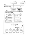
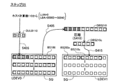
図1は、本発明の一実施例としてのストレージシステムの構成を示す説明図である。このストレージシステム200は、ホストインターフェイス210と、管理インターフェイス220と、ディスクインターフェイス230と、各インターフェイス210、220、230に接続されたディスクアレイ制御部300と、ディスクインターフェイス230に接続されたディスクアレイ250と、を有している。ディスクアレイ250は、複数のディスク装置を有している。
A. First embodiment:
A1. Device configuration:
FIG. 1 is an explanatory diagram showing the configuration of a storage system as an embodiment of the present invention. The
ホストインターフェイス210には、ホスト計算機110が接続される。このホスト計算機110は、ストレージシステム200によって提供されるデータ記憶領域を利用しつつ、所定の機能を実現する。ホスト計算機110の機能としては、例えば、データファイルをクライアント装置(図示せず)に提供するファイルサーバとしての機能や、種々のデータを管理するデータベースサーバとしての機能がある。
A
管理インターフェイス220には、管理端末120が接続される。ストレージシステム200の管理者(オペレータ)は、この管理端末120を操作することによって、ストレージシステム200の動作の設定を行うことができる。
A
ディスクアレイ制御部300は、CPU310と、データ圧縮回路320と、データ伸長回路330と、メモリ部340と、を有している。これらの各構成要素はバス390を介して互いに接続されている。また、メモリ部340は、キャッシュメモリ342と、ローカルメモリ344と、を有している。キャッシュメモリ342は、ディスクアレイ250とホスト計算機110との間で転送されるデータを一時的に記憶する。また、ローカルメモリ344は、CPU310が種々のデータ処理(詳細は後述)を実行する際に用いるデータとプログラムとを記憶する。
The disk
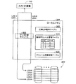
図2は、ローカルメモリ344の内部構成を示す概略図である。ローカルメモリ344は、圧縮LBA管理テーブル500と、論理ボリューム管理テーブル510と、ボリューム状態管理テーブル520と、データ中継モジュール600と、を有している。データ中継モジュール600は、ホスト計算機110とディスクアレイ250との間のデータ転送を中継する機能を有している(詳細は後述)。データ中継モジュール600の機能は、CPU310(図1)が実行するコンピュータプログラムによって実現されている。
FIG. 2 is a schematic diagram showing the internal configuration of the
また、データ中継モジュール600は、ディスクアレイ250を用いたRAID(Redundant Array of Inexpensive Disks)システムを構成する。図2の例では、データ中継モジュール600は、RAIDシステムを構成することによって、5つの論理ボリュームLDEV0〜LDEV4を形成している。
The
ここで、論理ボリュームとは、複数の論理ブロックを含むデータの記憶領域である。論理ブロックとは、論理ボリュームを対象とするデータ転送の最小単位である。第1実施例では、各論理ボリュームLDEV0〜LDEV4の論理ブロックのデータサイズは同一である。1つの論理ボリューム内の論理ブロックは、各論理ブロック毎に固有な論理ブロックアドレス(以下「LBA」とも呼ぶ)によって識別される。第1実施例では、LBAとして、「0」から始まる通し番号が用いられる。データ中継モジュール600は、LBAを用いてアクセス対象の論理ブロックを特定する。以下、論理ボリュームのことを、「論理デバイス」、あるいは、単に「ボリューム」とも呼ぶ。また、論理ブロックのことを、単に「ブロック」とも呼ぶ。また、データ中継モジュール600は、各論理ボリュームを識別するために、各論理ボリューム(論理デバイス)に固有な番号(以下「LDEVN」とも呼ぶ)を割り当てる。図2の例では、5つの論理ボリュームに0〜4までの番号を割り当てている。
Here, the logical volume is a data storage area including a plurality of logical blocks. A logical block is a minimum unit of data transfer for a logical volume. In the first embodiment, the logical block data sizes of the logical volumes LDEV0 to LDEV4 are the same. A logical block in one logical volume is identified by a unique logical block address (hereinafter also referred to as “LBA”) for each logical block. In the first embodiment, a serial number starting from “0” is used as the LBA. The
さらに、データ中継モジュール600は、論理ボリュームを選択的にホスト計算機110に利用させる。図2の例では、データ中継モジュール600は、2つの論理ボリュームLDEV0、LDEV4をホスト計算機110に提供している。このように、ホスト計算機110が利用可能な論理ボリュームのことを「論理ユニット」と呼ぶ。データ中継モジュール600は、論理ユニットに、各論理ユニット毎に固有な論理ユニット番号(以下「LUN」とも呼ぶ)を割り当てる。図2の例では、第0論理ボリュームLDEV0に「0番」を割り当て、第4論理ボリュームLDEV4に「1番」を割り当てている。このようなLUNとLDEVNとの対応関係は、論理ボリューム管理テーブル510に格納されている。
Further, the
第1実施例では、ホスト計算機110とデータ中継モジュール600との間のデータ転送の最小単位は論理ブロックであり、データ中継モジュール600と論理ボリュームとの間のデータ転送の最小単位(論理ブロック)と同じである。ホスト計算機110は、LUNとLBAとを指定することによって、論理ユニットに対するデータ転送の要求を行う。データ中継モジュール600は、ホスト計算機110からの要求に応じて、論理ボリュームを対象とするデータ転送を中継する。ただし、後述するように、第1実施例では、複数の論理ブロックに格納されるべきデータが、まとめて圧縮され、より少ない数の論理ブロックに格納される。従って、ホスト計算機110によって指定されたLBAと、データ転送に用いられる実際の論理ブロックのLBAとは、異なっている場合がある。このような指定されたLBAと実際のLBAとの対応関係は、圧縮LBA管理テーブル500に格納されている(詳細は後述)。以下、ホスト計算機110によって指定されたLBAを「指定LBA」とも呼ぶ。
In the first embodiment, the minimum unit of data transfer between the
A2.圧縮処理:
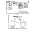
図3は、管理端末120に表示される設定画面の一例を示す説明図である。この設定画面は、論理ボリュームの圧縮マイグレーションを行うための設定画面である。圧縮マイグレーションとは、論理ボリュームに格納されたデータを圧縮して格納し直す処理を意味している。第1実施例では、1つの論理ボリューム全体のデータを、圧縮させつつ他の論理ボリュームに移行させることとしている。オペレータは、図3に示す設定画面を操作することによって、処理対象(移行元)の論理ボリュームと、処理内容と、処理のアルゴリズムと、を選択することができる。図3の例では、「第0論理ボリュームLDEV0」が選択されている。また、移行時の処理として「圧縮」が選択され、圧縮処理のアルゴリズムとして「LHA」が選択されている。移行時の処理としては、圧縮以外にも「暗号化」を選択することが可能である(後述)。圧縮処理のアルゴリズムとしては、LHA以外にもZIPを選択することが可能である。オペレータが、「OKボタン」を操作すると、ディスクアレイ制御部300(図1)は、圧縮マイグレーション処理を開始する。なお、移行先の論理ボリュームについては、データ中継モジュール600が、空いている論理ボリュームの中から自動的に選択する。図3の例では、第1論理ボリュームLDEV1が選択されている。ただし、オペレータが選択できることとしてもよい。
A2. Compression process:
FIG. 3 is an explanatory diagram illustrating an example of a setting screen displayed on the
図4は、圧縮マイグレーション処理の概要を示す説明図である。図4には、第0論理ボリュームLDEV0と第1論理ボリュームLDEV1とが示されている。各論理ボリュームLDEV0、LDEV1は、同数の論理ブロックLBを有している。 FIG. 4 is an explanatory diagram showing an outline of the compression migration process. FIG. 4 shows the 0th logical volume LDEV0 and the first logical volume LDEV1. Each logical volume LDEV0, LDEV1 has the same number of logical blocks LB.
第0論理ボリュームLDEV0は、非圧縮領域A1と、圧縮領域A2と、に区分されている。この区分は予め設定されたものである。また、各論理ブロックと各領域との対応関係は、ローカルメモリ344に予め格納されている。例えば、論理ボリュームにファイルシステムを構築すると、論理ボリュームが、データファイルを格納するデータ領域と、データファイルを管理する情報(例えば、ファイル名とLBAとの対応関係)を格納する管理領域と、に区分される場合がある。このような場合には、管理領域が非圧縮領域A1に設定され、データ領域が圧縮領域A2に設定される。一般には、非圧縮領域A1として、アクセス頻度が比較的高いデータを格納する部分領域を採用し、圧縮領域A2として、アクセス頻度が比較的低いデータを格納する部分領域を採用することが好ましい。また、論理ボリュームの全領域を圧縮領域として採用してもよい。なお、オペレータが、このような区分を設定することとしてもよい。
The 0th logical volume LDEV0 is divided into an uncompressed area A1 and a compressed area A2. This classification is set in advance. The correspondence between each logical block and each area is stored in advance in the
図5は、圧縮マイグレーション処理の手順を示すフローチャートである。データ中継モジュール600(図2)は、前(LBAの小さい方)から順番に圧縮単位でデータを移行させる。第1実施例では、圧縮単位は、LBAが連続する10個の論理ブロックで構成されるブロックセットである。論理ボリュームLDEV0は、複数のブロックセットに区分されることとなる。 FIG. 5 is a flowchart showing the procedure of the compression migration process. The data relay module 600 (FIG. 2) migrates data in units of compression in order from the previous (smaller LBA). In the first embodiment, the compression unit is a block set composed of 10 logical blocks in which LBAs are continuous. The logical volume LDEV0 is divided into a plurality of block sets.
まず、非圧縮領域A1内のデータを移行する場合の手順について説明する。ステップS100では、データ中継モジュール600が、移行元論理ボリュームLDEV0内の1つのブロックセットからデータを読み出す。図4上側の例では、データ中継モジュール600が、非圧縮領域A1内の第1ブロックセットBS1からデータDBS1を読み出している。
First, a procedure for migrating data in the uncompressed area A1 will be described. In step S100, the
次のステップS105では、データ中継モジュール600は、読み出し元のブロックセットが圧縮領域A2内であるか否かを判断する。図4上側の例では、第1ブロックセットBS1は非圧縮領域A1内である。従って、データ中継モジュール600は、ステップS140に移行する。ステップS140では、データ中継モジュール600は、読み出したデータをそのまま移行先論理ボリュームLDEV1に格納する。ここで、「そのまま格納する」とは、データの中身を変えずに格納するという意味である。この際、移行先の論理ブロックを、前(LBAの小さい方)から順番に選択する。図4の例では、データDBS1が第1ブロックセットBS11に格納されている。各ブロックセットBS1、BS11は、同数の論理ブロックを含んでいる。
In the next step S105, the
次のステップS120では、データ中継モジュール600は、圧縮LBA管理テーブル500を更新する。図6(A)は、圧縮LBA管理テーブル500の一例を示す説明図である。圧縮LBA管理テーブル500は、圧縮前後、すなわち、移行前後のブロックセットのペアと、移行時に圧縮したか否かに関する情報と、の対応関係を格納している。図6(A)の例では、ブロックセットは、先頭LBAとサイズ(ブロック数)との組み合わせによって特定される。データ中継モジュール600は、移行前の第1ブロックセットBS1と移行後の第1ブロックセットBS11との対応関係を圧縮LBA管理テーブル500に格納する。図6(A)の例では、第1ブロックセットBS1については、先頭LBAが「0000」で、サイズが「10」である。また、移行後の第1ブロックセットBS11についても、先頭LBAが「0000」で、サイズが「10」である。
In the next step S120, the
なお、圧縮LBA管理テーブル500に格納する情報としては、先頭LBAとサイズとの組み合わせに限らず、ブロックセットを特定可能な任意の情報を採用することが可能である。例えば、先頭LBAと終端LBAとの組み合わせを採用してもよい。 The information stored in the compressed LBA management table 500 is not limited to the combination of the head LBA and the size, but can be any information that can identify a block set. For example, a combination of a head LBA and a terminal LBA may be employed.
次のステップS125では、データ中継モジュール600は、全データの移行が終了したか否かを判定する。終了していない場合には、ステップS100に戻る。
In the next step S125, the
次に、圧縮領域A2内のデータを移行する場合の手順について説明する。図4の下側の例では、データ中継モジュール600が、圧縮領域A2内の第5ブロックセットBS5からデータDBS5を読み出している(ステップS100)。
Next, a procedure for migrating data in the compression area A2 will be described. In the lower example of FIG. 4, the
ステップS100が終了したら、データ中継モジュール600は、ステップS105に移行する。第5ブロックセットBS5は圧縮領域A2内であるので、ステップS110に移行する。
When step S100 ends, the
ステップS110では、データ中継モジュール600は、データ圧縮回路320(図1)に、読み出したデータを圧縮させる。この際、図3の設定画面で指定されたアルゴリズムが使用される。図4の例では、データ圧縮回路320は、データDBS5を圧縮することによって、データDBS15cを生成している。この圧縮後のデータDBS15cのサイズは、5ブロックである。
In step S110, the
次のステップS115では、データ中継モジュール600は、圧縮後のデータを移行先論理ボリュームLDEV1に格納する。この際、移行先のブロックを、前(LBAの小さい方)から順番に選択する。図4の例では、データDBS15cが第5ブロックセットBS15cに格納されている。この第5ブロックセットBS15cのサイズは、5ブロックである。
In the next step S115, the
次のステップS120では、データ中継モジュール600は、移行前後のブロックセットBS5、BS15cの対応関係を圧縮LBA管理テーブル500に格納する。図6(A)の例では、移行前の第5ブロックセットBS5については、先頭LBAが「7990」で、サイズが「10」である。移行後の第5ブロックセットBS15cについては、先頭LBAが「5808」で、サイズが「5」である。
In the next step S120, the
他のブロックセットについても、同様に移行処理が実行される。図4の例では、第2ブロックセットBS2は、第2ブロックセットBS12に移行し、第3ブロックセットBS3は、圧縮された後に、第3ブロックセットBS13cに移行し、第4ブロックセットは、圧縮された後に、第4ブロックセットBS14cに移行する。なお、図5の例では、ステップS100からステップS125へ至る一連の処理が、1つのブロックセット毎に実行されていたが、複数のブロックセット毎に実行することとしてもよい。 The migration process is executed in the same manner for other block sets. In the example of FIG. 4, the second block set BS2 moves to the second block set BS12, the third block set BS3 moves to the third block set BS13c after being compressed, and the fourth block set BS Then, the process proceeds to the fourth block set BS14c. In the example of FIG. 5, the series of processing from step S100 to step S125 is executed for each block set, but may be executed for each of a plurality of block sets.
こうして全データの移行か終了したら、次のステップS130で、データ中継モジュール600は、ボリューム状態管理テーブル520を更新する。図6(B)は、ボリューム状態管理テーブル520の一例を示す説明図である。ボリューム状態管理テーブル520は、LDEVNと、圧縮の有無と、暗号化の有無と、アルゴリズムと、の対応関係を格納している。データ中継モジュール600は、移行先論理ボリュームLDEV1に関する情報として、「圧縮:有効」、「暗号化:無効」、「アルゴリズム:LHA」を格納する。
When the migration of all data is completed, the
次のステップS135では、データ中継モジュール600は、論理ボリューム管理テーブル510を更新する。図6(C)は、論理ボリューム管理テーブル510の一例を示す説明図である。データ中継モジュール600は、第0論理ユニットLU0に対応するLDEVNを「0」から「1」へ変更する。
In the next step S135, the
以上の処理が終了したら、ディスクアレイ制御部300は、圧縮マイグレーション処理を終了する。この結果、移行先論理ボリュームLDEV1には、非圧縮領域A11と、圧縮領域A12と、空き領域A13と、が形成されることとなる。
When the above processing ends, the disk
A3.読み出し処理:
図7は、ストレージシステム200に対するデータ読み出し処理の手順を示すフローチャートである。上述したように、ホスト計算機110は、ストレージシステム200に対して、LUNとLBAとを指定して、データの読み出し要求を行う。以下、第1論理ボリュームLDEV1(LUN=0)が指定されたものとして説明を行う。
A3. Reading process:
FIG. 7 is a flowchart showing a procedure of data read processing for the
図8は、読み出し処理の概要を示す説明図である。図8の上側には、非圧縮領域A11からデータを読み出す場合が示され、下側には、圧縮領域A12からデータを読み出す場合が示されている。 FIG. 8 is an explanatory diagram showing an outline of the reading process. The upper side of FIG. 8 shows a case where data is read from the non-compressed area A11, and the lower side shows a case where data is read from the compressed area A12.
まず、非圧縮領域A11内のデータを読み出す場合の手順について説明する。ステップS200(図7)では、データ中継モジュール600が、指定された論理ブロックを含む移行前ブロックセットと、移行後ブロックセットと、の組み合わせを、圧縮LBA管理テーブル500(図6(A))から検索する。図8の上側の例では、指定LBAが「0005」から「0009」までである。この場合には、第1ブロックセットBS1と第1ブロックセットBS11との組み合わせを検出する。
First, a procedure for reading data in the uncompressed area A11 will be described. In step S200 (FIG. 7), the
次のステップS205では、データ中継モジュール600は、検出したブロックセットが圧縮処理の対象であるか否かを判定する。この判定は、圧縮LBA管理テーブル500を参照することによって行われる。図8の上側の例では「No」と判定する。
In the next step S205, the
次のステップS240では、データ中継モジュール600は、第1論理ボリュームLDEV1内の、ステップS200で検出した移行後ブロックセットからデータを読み出す。図8の上側の例では、第1ブロックセットBS11からデータDBS1を読み出す。
In the next step S240, the
次のステップS230では、データ中継モジュール600は、読み出したデータの中から、指定LBAに対応付けられたデータを取得して、ホスト計算機110に転送する。図8の上側の例では、データDBS1に含まれる10ブロック分のデータの中の、5番目から9番目までが、それぞれ、「LBA=0005」から「LBA=0009」までの各論理ブロックのデータとなる。
In the next step S230, the
次のステップS235では、データ中継モジュール600は、指定LBAの全てについてデータ転送が終了したか否かを判定する。終了していない場合には、ステップS200に戻り、データ転送の終了していない指定LBAについて、ステップS200からステップS230へ至る一連の処理を繰り返し実行する。これらの一連の処理は1つのブロックセット毎に実行される。ただし、複数のブロックセット毎に実行してもよい。
In the next step S235, the
次に、圧縮領域A12(図8)内のデータを読み出す場合の手順について説明する。図8の下側には、指定LBAが「7990」から「7994」までである場合が示されている。この場合には、データ中継モジュール600は、ステップS200で、第5ブロックセットBS5と第5ブロックセットBS15cとの組み合わせを検出する(図6(A))。
Next, a procedure for reading data in the compression area A12 (FIG. 8) will be described. In the lower part of FIG. 8, a case where the designated LBA is “7990” to “7994” is shown. In this case, the
ステップS200が終了したら、データ中継モジュール600は、次のステップS205に移行する。図8の下側の例では「Yes」と判定する。
When step S200 ends, the
次のステップS210では、データ中継モジュール600は、ステップS200で検出した移行後ブロックセットからデータを読み出す。図8の下側の例では、第5ブロックセットBS5に対応付けられた第5ブロックセットBS15cからデータDBS15cを読み出す。
In the next step S210, the
なお、指定LBAを含む移行前の第5ブロックセットBS5が、本発明における「第1ブロックセット」に相当する。また、移行後の第5ブロックセットBS15cが、本発明における「第2ブロックセット」に相当する。また、LUNと圧縮前の先頭LBAと圧縮前のサイズとの全体が、本発明における「第1ブロックセットの論理的な格納位置」を示す情報に相当する。また、LDEVNと圧縮後の先頭LBAと圧縮後のサイズとの全体が、本発明における「第2ブロックセットの物理的な格納位置」を示す情報に相当する。 The fifth block set BS5 before the transition including the designated LBA corresponds to the “first block set” in the present invention. Further, the fifth block set BS15c after the migration corresponds to the “second block set” in the present invention. The entire LUN, the leading LBA before compression, and the size before compression correspond to information indicating the “logical storage position of the first block set” in the present invention. Also, the entire LDEVN, the compressed first LBA, and the compressed size correspond to information indicating “physical storage location of the second block set” in the present invention.
次のステップS225では、データ中継モジュール600は、データ伸長回路330(図1)に、読み出したデータを伸長させる。この伸長処理は、データ圧縮回路320が実行した圧縮処理の逆変換処理である。データ伸長回路330は、ボリューム状態管理テーブル520(図6(B))を参照することによって、適切なアルゴリズムの伸長処理を選択する。図8の下側の例では、データ伸長回路330は、データDBS15cを伸長することによって、データDBS5を生成する。
In the next step S225, the
次のステップS230では、データ中継モジュール600は、生成されたデータの中から、指定LBAに対応付けられたデータを取得して、ホスト計算機110に転送する。図8の下側の例では、データDBS5に含まれる10ブロック分のデータの中の、0番目から4番目までのデータが、それぞれ、「LBA=7990」から「LBA=7994」までの各ブロックのデータとなる。
In the next step S230, the
こうして全指定LBAのデータ転送が終了したら、ディスクアレイ制御部300は、データ読み出し処理を終了する。
When the data transfer of all the specified LBAs is thus completed, the disk
以上説明した読み出し処理では、ストレージシステム200は、圧縮LBA管理テーブル500を有し、さらに、データ中継モジュール600は、この圧縮LBA管理テーブル500を参照することによってデータを読み出して伸長し、ホスト計算機110に要求された論理ブロックのデータを転送する。従って、ストレージシステム200がデータを圧縮して格納する場合であっても、ホスト計算機110は、伸長処理や圧縮データの管理を行うことなく、圧縮前のLBAを指定することによってデータの読み出しを行うことが可能となる。
In the read processing described above, the
A4.書き込み処理:
図9は、ストレージシステム200に対するデータ書き込み処理の手順を示すフローチャートである。読み出し処理と同様に、ホスト計算機110は、ストレージシステム200に対して、LUNとLBAとを指定して、データの書き込み要求を行う。以下、第1論理ボリュームLDEV1(LUN=0)が指定されたものとして説明を行う。
A4. Write process:
FIG. 9 is a flowchart showing a procedure of data write processing for the
図10は、書き込み処理の概要を示す説明図である。図10は、圧縮領域A12内にデータを書き込む場合の処理の概要を示している。まず、ステップS300(図9)では、データ中継モジュール600は、指定LBAが、1つの圧縮単位(ブロックセット)の全ての論理ブロックを含むか否かを判定する。この判定は、圧縮LBA管理テーブル500(図6(A))を参照することによって行われる。図10には、指定LBAが「7990」から「7995」までの場合が示されている。指定されたブロックは、第5ブロックセットBS5の一部の(6つの)論理ブロックのみである。従って、この場合には、データ中継モジュール600は「No」と判定する。
FIG. 10 is an explanatory diagram showing an outline of the writing process. FIG. 10 shows an outline of processing when data is written in the compression area A12. First, in step S300 (FIG. 9), the
なお、指定LBAが複数の圧縮単位(ブロックセット)のブロックを含む場合がある。このような場合には、データ中継モジュール600は、各ブロックセット毎に、ステップS300に続く一連の処理(後述)を実行する。
The designated LBA may include a plurality of blocks of compression units (block sets). In such a case, the
次のステップS305では、データ中継モジュール600が、圧縮LBA管理テーブル500(図6(A))を参照することによって、指定された論理ブロックを含む移行前ブロックセットと、移行後ブロックセットと、の組み合わせを検索する。この処理は、図7のステップS200の処理と同じである。図10の例では、第5ブロックセットBS5と第5ブロックセットBS15cとの組み合わせを検出する。
In the next step S305, the
次のステップS310では、データ中継モジュール600は、ステップS305で検出した移行後ブロックセットからデータを読み出す。図10の例では、第5ブロックセットBS15cからデータDBS15cを読み出す。
In the next step S310, the
次のステップS315では、データ中継モジュール600は、データ伸長回路330(図1)に、読み出したデータを伸長させる。この処理は、図7のステップS225と同じである。図10の例では、データ伸長回路330は、データDBS15cを伸長することによって、データDBS5を生成する。こうして生成されたデータは、更新対象のブロックセットの更新前のデータとして利用される。
In the next step S315, the
次のステップS320では、データ中継モジュール600は、更新前のデータに、ホスト計算機110に書き込み要求されたデータを上書きすることによって、圧縮単位の書き込みデータを生成する。図10の例では、データ中継モジュール600は、更新前データDBS5の0番目から5番目のブロックのデータを、ホスト計算機110から受け取った更新データDULBに置き換えることによって、更新後データDBS5uを生成する。
In the next step S320, the
次のステップS325では、データ中継モジュール600は、データ圧縮回路320(図1)に、更新後データを圧縮させる。この処理は、図5のステップS110の処理と同じである。図10の例では、データ圧縮回路320は、更新後データDBS5uを圧縮することによって圧縮後データDBS15ucを生成している。この新たな圧縮後データDBS15ucのサイズは、6ブロックである。
In the next step S325, the
なお、1つの圧縮単位(ブロックセット)の全ての論理ブロックのデータを更新する場合には、ステップS305からS320の処理が省略される。そして、書き込み要求された1ブロックセット分のデータが、更新後データとして圧縮される。 Note that when updating the data of all logical blocks in one compression unit (block set), the processing of steps S305 to S320 is omitted. Then, the data for one block set requested to be written is compressed as post-update data.
次のステップS330では、データ中継モジュール600は、圧縮後データを第1論理ボリュームLDEV1の空き領域A13に格納する。この際、格納先の論理ブロックを、前(LBAの小さい方)から順番に選択する。図10の例では、データDBS15ucが第5ブロックセットBS15ucに格納されている。
In the next step S330, the
このステップS330では、データ中継モジュール600は、空き領域A13内の未使用領域から論理ブロックを選択する。空き領域A13内の使用済領域と未使用領域とを区別する方法としては、任意の方法を採用可能である。例えば、データ中継モジュール600が、使用済領域と未使用領域との境界を示すLBAをローカルメモリ344に格納し、さらに、このLBAの参照と更新とを適宜実行する方法を採用可能である。
In step S330, the
次のステップS335では、データ中継モジュール600は、圧縮LBA管理テーブル500を更新する。図11は、更新後の圧縮LBA管理テーブル500の一例を示す説明図である。データ中継モジュール600は、第5ブロックセットBS5に対応付けられた移行後ブロックセットの情報を、古い第5ブロックセットBS15cから、新しい第5ブロックセットBS15ucのものに更新する。図11の例では、先頭LBAが「5813」で、サイズが「6」である。以後、データ中継モジュール600は、第5ブロックセットBS5に対する読み出し要求を受けると、新しい第5ブロックセットBS15ucからデータを読み出す。古い第5ブロックセットBS15cのデータは、以後、使用されない。
In the next step S335, the
次のステップS340では、データ中継モジュール600は、指定LBAの全てについて書き込みが終了したか否かを判定する。終了していない場合には、ステップ300に戻り、書き込みの終了していない指定LBAについて、ステップS300からステップS335へ至る一連の処理を繰り返し実行する。これらの一連の処理は1つのブロックセット毎に実行される。ただし、複数のブロックセット毎に実行してもよい。
In the next step S340, the
こうして全指定LBAのデータの書き込みが終了したら、次のステップS345で、データ中継モジュール600は、ホスト計算機110にデータ書き込み終了の通知を送信する。
When the writing of all the specified LBA data is completed in this manner, the
以上説明した書き込み処理では、データ中継モジュール600は、ホスト計算機110からデータ書き込み要求を受けると、データを圧縮して格納し、さらに、圧縮前後(移行前後)のブロックセットの新たな対応関係を圧縮LBA管理テーブル500に格納する。従って、ストレージシステム200がデータを圧縮して格納する場合であっても、ホスト計算機110は、圧縮処理や圧縮データの管理を行うことなく、圧縮前のLBAを指定することによってデータの書き込みを行うことが可能となる。
In the write processing described above, when the
また、指定LBAを含む移行前ブロックセットの全てのブロックの更新が要求されていない場合であっても、データ中継モジュール600は、ブロックセットの更新前のデータに、要求されたデータを上書きすることによって、ブロックセットを単位とする圧縮処理を実行する。その結果、圧縮後のデータの管理が過剰に複雑化することを防止できる。
Further, even when the update of all blocks in the pre-migration block set including the specified LBA is not requested, the
なお、更新後の圧縮後データを、更新前の圧縮後データを格納する論理ボリュームとは異なる論理ボリュームに格納することとしてもよい。こうすれば、空き領域A13よりも大きな記憶領域を有する論理ボリュームに更新後のデータを書き込むことが可能となるので、大量のデータ更新にも対応することが可能となる。この場合には、圧縮LBA管理テーブル500(図6(A))に、圧縮前後(移行前後)のブロックセットの対応関係に加えて、移行後のブロックセットを含むLDEVNを格納すればよい。 The post-compression data after update may be stored in a logical volume different from the logical volume that stores post-compression data before update. By doing this, it is possible to write updated data in a logical volume having a storage area larger than the free area A13, and thus it is possible to cope with a large amount of data update. In this case, the LDEVN including the block set after the migration may be stored in the compression LBA management table 500 (FIG. 6A) in addition to the correspondence relationship between the block sets before and after the compression (before and after the migration).
また、更新後の圧縮データが、更新前の圧縮データよりも小さい場合には、更新前の圧縮データを格納していた論理ブロックに、更新後の圧縮データを格納することとしてもよい。こうすれば、論理ブロックの利用効率の向上を図ることが可能となる。 In addition, when the compressed data after update is smaller than the compressed data before update, the compressed data after update may be stored in the logical block in which the compressed data before update is stored. In this way, it is possible to improve the utilization efficiency of the logical block.
A5.圧縮解除処理:
図12は、圧縮解除処理の手順を示すフローチャートである。圧縮解除処理とは、論理ボリュームに格納された圧縮データを伸長して格納し直す処理を意味している。第1実施例では、論理ボリューム1つ分のデータを、伸長させつつ他の論理ボリュームに移行させることとしている。圧縮解除処理は、管理端末120(図1)からの指示に従って、ディスクアレイ制御部300が実行する。以下、第1論理ボリュームLDEV1を第2論理ボリュームLDEV2に移行させることとして説明を行う。なお、伸長先(移行先)の論理ボリュームについては、データ中継モジュール600が、空いている論理ボリュームの中から自動的に選択する。ただし、オペレータが選択できることとしてもよい。
A5. Decompression processing:
FIG. 12 is a flowchart illustrating the procedure of the decompression process. Decompression processing means processing for decompressing and re-storing compressed data stored in a logical volume. In the first embodiment, data for one logical volume is transferred to another logical volume while being expanded. The decompression processing is executed by the disk
ディスクアレイ制御部300は、図7に示す読み出し処理と同様に、ブロックセット毎にデータを読み出し、さらに、読み出したデータを適宜伸長する。ただし、図7の読み出し処理との差異は3点ある。1つ目の差異は、ホスト計算機110によって指定されたデータの代わりに、論理ボリューム1つ分のデータを読み出す点である。2つ目の差異は、読み出したデータをホスト計算機110へ転送する処理(図7:ステップS230)の代わりに、伸長先(移行先)の論理ボリュームに書き込む処理(ステップS250)を実行している点である。3つ目の差異は、移行が完了した後に、ボリューム状態管理テーブル520(図6(B))と論理ボリューム管理テーブル510(図6(C))とを更新する点である(ステップS260、S265)。
The disk
ステップS200からステップS250へ至る処理は、図7の読み出し処理と同じである。 The processing from step S200 to step S250 is the same as the reading processing of FIG.
ステップS250では、データ中継モジュール600は、読み出したデータを、伸長先(移行先)の論理ボリュームに格納する。第1実施例では、データ中継モジュール600は、伸長先の論理ブロックのLBAと、圧縮前の論理ブロックのLBAと、が一致するように、伸長先の論理ブロックを選択する。
In step S250, the
次のステップS255では、データ中継モジュール600は、圧縮前LBAの全てについてのデータ移行が終了したか否かを判定する。終了していない場合には、ステップS200に戻り、データ移行の終了していないブロックセットについて、ステップS200からステップS250へ至る一連の処理を繰り返し実行する。これらの一連の処理は1つのブロックセット毎に実行される。ただし、複数のブロックセット毎に実行してもよい。
In the next step S255, the
データ移行が終了したら、次のステップS260で、データ中継モジュール600は、ボリューム状態管理テーブル520(図6(B))における、伸長先の論理ボリュームに関する情報を更新する。例えば、伸長先の第2論理ボリュームLDEV2に関して、「圧縮:無効」、「暗号化:無効」、「アルゴリズム:無し」に設定する。
When the data migration is completed, in the next step S260, the
次のステップS265では、データ中継モジュール600は、論理ボリューム管理テーブル510におけるLDEVNを切り替える。例えば、データ中継モジュール600は、第0論理ユニットLU0に対応するLDEVNを「1」から「2」へ変更する。なお、LDEVNの切り替えは、管理端末120からの指示に従ったタイミングで行うこととしてもよい。
In the next step S265, the
以後、データ中継モジュール600は、第0論理ユニットLU0を対象とするデータ転送要求(例えば、読み出し要求や、書き込み要求)を受けると、新しい第2論理ボリュームLDEV2を対象とするデータ転送を行う。この際、論理ボリュームに対するLBAとしては、指定LBA(圧縮前のLBA)をそのまま用いる。
Thereafter, when receiving a data transfer request (for example, a read request or a write request) for the 0th logical unit LU0, the
以上説明した圧縮解除処理では、ディスクアレイ制御部300は、ホスト計算機110に負荷をかけることなく、データの伸長を行う。さらに、データ中継モジュール600は、圧縮前LBAと伸長先のLBAとが一致するように、伸長後のデータを格納する論理ブロックを選択する。従って、ストレージシステム200が圧縮を解除する場合であっても、ホスト計算機110は、伸長処理や伸長データの管理を行うことなく、圧縮前のLBAを指定することによってデータ転送要求を行うことが可能である。
In the decompression process described above, the disk
なお、伸長先の論理ブロックのLBAと、圧縮前の論理ブロックのLBAとは、一致していなくてもよい。この場合には、ストレージシステム200に、圧縮前のLBAと伸長後のLBAとの対応関係を格納しておくことが好ましい。こうすれば、データ中継モジュール600は、データ転送要求を受けた場合には、このような対応関係を参照することによって、適切なデータ転送を行うことができる。
It should be noted that the LBA of the decompression destination logical block and the LBA of the logical block before compression need not match. In this case, it is preferable to store the correspondence relationship between the LBA before compression and the LBA after decompression in the
以上説明した第1実施例によれば、ディスクアレイ制御部300(図1)は、ホスト計算機110から独立して圧縮マイグレーション処理を実行するので、ホスト計算機110に負荷をかけずに記憶領域の節約を図ることが可能となる。
According to the first embodiment described above, since the disk array control unit 300 (FIG. 1) executes the compression migration process independently of the
また、第1実施例では、論理ボリュームのデータが、複数のブロックセットに分割して圧縮される。従って、論理ボリューム全体を1つのデータとして圧縮する場合と比べて、論理ボリュームの部分領域を対象とするデータ転送処理の速度が過剰に遅くなることを防止できる。 In the first embodiment, the data of the logical volume is compressed by being divided into a plurality of block sets. Accordingly, it is possible to prevent the data transfer processing speed for the partial area of the logical volume from being excessively slow compared to the case where the entire logical volume is compressed as one data.
さらに、第1実施例では、ストレージシステム200は、圧縮前後のブロックセットの対応関係に関する管理データ(圧縮LBA管理テーブル500と、論理ボリューム管理テーブル510と、ボリューム状態管理テーブル520)を格納するとともに、データの圧縮と伸長と、管理データの更新とを、ホスト計算機110から独立して実行する。従って、ホスト計算機110に負荷をかけずに、データの圧縮と伸長とを実行することができる。
Furthermore, in the first embodiment, the
特に、第1実施例では、ストレージシステム200は、ホスト計算機110に指定させるためのLBA(圧縮前LBA)と、実際のLBA(圧縮後LBA)と、の対応関係を格納する圧縮LBA管理テーブル500を有している。その結果、ディスクアレイ制御部300は、ホスト計算機110からは、データの圧縮状況(圧縮の有無や、データを格納するブロックのLBAの変更)に拘わらずに一貫して、圧縮前LBAを指定するデータ転送要求を受けることが可能である。換言すれば、ディスクアレイ制御部300は、データの圧縮状況を、ホスト計算機110から隠すことが可能である。従って、ホスト計算機110は、データの圧縮状況の管理をすることなく、所定の圧縮前LBAを用いたデータ転送を要求することができる。
In particular, in the first embodiment, the
また、複数のホスト計算機でストレージシステム200に格納されたデータを共有する場合であっても、各ホスト計算機は、データの圧縮状況に拘わらずに、共通の圧縮前LBAを用いてデータ転送要求を行うことができる。このように、第1実施例のストレージシステム200は、データの圧縮状況に拘わらずに、ホスト計算機を限定せずに記憶領域を提供することが可能である。以下、ホスト計算機を限定せずに動作可能なことを「ホスト透過(Host Transparent)」とも呼ぶ。
Even when a plurality of host computers share data stored in the
なお、第1実施例では、圧縮LBA管理テーブル500と論理ボリューム管理テーブル510との全体が、本発明における「ブロック対応関係」に相当する。 In the first embodiment, the entire compression LBA management table 500 and logical volume management table 510 correspond to the “block correspondence” in the present invention.
B.第2実施例:
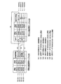
図13は、第2実施例におけるストレージシステム200bの構成を示す説明図である。図1に示すストレージシステム200との差異は、データ中継モジュール600bが、データの更新履歴を保存するとともに、その更新履歴を世代管理する点である。また、ローカルメモリ344bは、圧縮LBA管理テーブル500の代わりに、更新状態管理テーブル530と、世代・圧縮管理テーブル540と、を格納している。これらのテーブル530、540は、世代管理に用いられる。他の構成は、図1、図2のストレージシステム200と同じである。なお、図13では、ストレージシステム200bの構成要素として、ディスクアレイ制御部300bのローカルメモリ344bのみが示されており、他の構成要素は図示が省略されている。
B. Second embodiment:
FIG. 13 is an explanatory diagram showing the configuration of the
第2実施例では、第0論理ユニットLU0と第0論理ボリュームLDEV0とが対応付けられている(図13:論理ボリューム管理テーブル510)。また、第0論理ボリュームLDEV0のデータは、圧縮されていない。そこで、データ中継モジュール600bは、第0論理ボリュームLDEV0に対するLBAとしては、指定LBAをそのまま用いる。 In the second embodiment, the 0th logical unit LU0 and the 0th logical volume LDEV0 are associated (FIG. 13: logical volume management table 510). The data of the 0th logical volume LDEV0 is not compressed. Therefore, the data relay module 600b uses the designated LBA as it is as the LBA for the 0th logical volume LDEV0.
また、データ中継モジュール600bは、第0論理ボリュームLDEV0におけるデータの更新履歴を保存し、さらに、その更新履歴を世代管理する。これは、最新のデータに加えて、過去のある時点における第0論理ボリュームLDEV0のデータを、ホスト計算機110に提供するためである。このような、過去のある時点におけるデータのバックアップは「時点コピー(Point In Time Copy)」や「スナップショット(Snapshot)(商標)」とも呼ばれている。
Further, the data relay module 600b stores the data update history in the 0th logical volume LDEV0, and further manages the generation history of the update history. This is to provide the
データ中継モジュール600bは、ホスト計算機110や管理端末120から「時点コピー」を作成するように指示を受ける。すると、データ中継モジュール600bは、指示を受けた時点(以下「指示時点」と呼ぶ)での任意の論理ブロックのデータを後で提供できるように、バックアップデータを保存する。この際、バックアップデータとして、指示時点以降に更新された部分領域のみの更新前データを保存する。このような、更新(変更)部分のみをコピーする処理は「コピー・オン・ライト(Copy On Write)」とも呼ばれている。なお、データ中継モジュール600bは、バックアップデータを、元の第0論理ボリュームLDEV0とは異なる第1論理ボリュームLDEV1に格納する。この際、バックアップデータを圧縮して格納する(詳細は後述)。
The data relay module 600 b receives an instruction to create a “time copy” from the
B1.書き込み処理(更新処理):
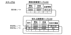
図14は、更新状態管理テーブル530と世代・圧縮管理テーブル540との一例を示す説明図である。これらのテーブル530、540は、図14の下側に示したステップS1からS7の手順に従ってデータの更新が行われた場合の例を示している。
B1. Write process (update process):
FIG. 14 is an explanatory diagram showing an example of the update state management table 530 and the generation / compression management table 540. These tables 530 and 540 show an example in the case where data is updated according to the procedure of steps S1 to S7 shown on the lower side of FIG.
更新状態管理テーブル530は、第0論理ボリュームLDEV0内のブロックセットと、退避情報の有無と、の対応関係を格納している。第2実施例では、データ中継モジュール600bは、第0論理ボリュームLDEV0を複数のブロックセットに区分する。さらに、このブロックセットを処理単位として、更新履歴の保存と世代管理とを行う。図14の例では、処理単位は、LBAが連続する100(16進法)個の論理ブロックで構成されるブロックセットである。更新状態管理テーブル530では、ブロックセットが、開始LBAと終端LBAとの組み合わせによって特定されている。図14には、4つのブロックセットBS100〜BS130の例が示されている。一方、退避情報としては、更新前データの退避状況を表す情報(詳細は後述)を参照するポインタが用いられる。データが更新されていないブロックセットに対しては、ポインタは設定されない。 The update state management table 530 stores the correspondence between the block set in the 0th logical volume LDEV0 and the presence / absence of save information. In the second embodiment, the data relay module 600b partitions the 0th logical volume LDEV0 into a plurality of block sets. Furthermore, update history storage and generation management are performed using this block set as a processing unit. In the example of FIG. 14, the processing unit is a block set composed of 100 (hexadecimal) logical blocks in which LBAs are continuous. In the update state management table 530, the block set is specified by a combination of the start LBA and the end LBA. FIG. 14 shows an example of four block sets BS100 to BS130. On the other hand, as the save information, a pointer that refers to information (details will be described later) indicating the save status of the pre-update data is used. No pointer is set for a block set whose data has not been updated.
なお、LBAに付された符号「(h)」は、LBAが16進法で表されていることを意味している。以下、符号「(h)」が付されたLBAは「16進法」で表され、何も付されていないLBAは「10進法」で表されていることとする。 Note that the symbol “(h)” added to the LBA means that the LBA is expressed in hexadecimal. Hereinafter, it is assumed that LBAs with the symbol “(h)” are expressed in “hexadecimal”, and LBAs with nothing added are expressed in “decimal”.
一方、世代・圧縮管理テーブル540は、更新前データの退避状況を格納している。具体的には、更新前データを格納するブロックセットと、その更新前データの世代番号と、他世代の更新前データの情報を参照するポインタと、の対応関係を格納している。他世代の情報を参照するポインタは、この世代・圧縮管理テーブル540の中の他の1つの対応関係を参照している。また、上述の更新状態管理テーブル530における「ポインタ」は、この世代・圧縮管理テーブル540の中の1つの対応関係を参照している。世代番号については後述する。 On the other hand, the generation / compression management table 540 stores the save status of pre-update data. Specifically, a correspondence relationship between a block set for storing pre-update data, a generation number of the pre-update data, and a pointer for referring to information of pre-update data of other generations is stored. A pointer that refers to information of another generation refers to another correspondence relationship in the generation / compression management table 540. The “pointer” in the update state management table 530 refers to one correspondence in the generation / compression management table 540. The generation number will be described later.
まず、最初のステップS1では、管理端末120がディスクアレイ制御部300bへ
時点コピーの作成指示を送信する。このような指示は、オペレータの操作によって送信される。また、ディスクアレイ制御部300b、あるいは、管理端末120が、予め設定されたタイミングで自発的に指示を行ってもよく、また、他の任意の条件に従って自発的に指示を行うこととしてもよい。
First, in the first step S1, the
第2実施例では、ディスクアレイ制御部300bは、時点が異なる複数の時点コピーを作成可能である。時点コピーは、各時点コピー毎に固有な世代番号によって識別される。第2実施例では、世代番号として、「0」から始まる通し番号が用いられる。図14の例では、データ中継モジュール600bは、ステップS1で指示された時点コピーに「0番」を割り当てている。なお、世代(時点)は、本発明における「バージョン」に相当する。
In the second embodiment, the disk
次のステップS2では、ホスト計算機110が、ストレージシステム200bに対して、データの書き込み要求を行う。ここで、指定LBAは「00000〜00050(h)」であることとしている。
In the next step S2, the
図15は、データ書き込み処理の手順を示すフローチャートである。最初のステップS400では、データ中継モジュール600bは、データ退避の要否を判定する。指定LBAを含むブロックセット(以下「指定ブロックセット」とも呼ぶ)に対する書き込みが、最新の指示時点以降の最初の書き込みである場合、すなわち、指定ブロックセットのデータが最新の指示時点以降に1度も退避されていない場合には、「退避要」と判定する。指定ブロックセットのデータが最新の指示時点以降に既に退避されている場合には、「退避不要」と判定する。ステップS2(図14)の書き込み処理では、「退避要」と判定する。 FIG. 15 is a flowchart showing the procedure of the data writing process. In the first step S400, the data relay module 600b determines whether data saving is necessary. When the writing to the block set including the designated LBA (hereinafter also referred to as “designated block set”) is the first writing after the latest designated time, that is, the data of the designated block set is once after the latest designated time. If it has not been saved, it is determined that “evacuation is required”. When the data of the designated block set has already been saved after the latest instruction time, it is determined that “saving is not necessary”. In the writing process in step S2 (FIG. 14), it is determined that “saving is necessary”.
なお、指定LBAが複数の処理単位(ブロックセット)のブロックを含む場合がある。このような場合には、データ中継モジュール600bは、各ブロックセット毎に、ステップS400に続く一連の処理(後述)を実行する。 The designated LBA may include a plurality of processing unit (block set) blocks. In such a case, the data relay module 600b executes a series of processes (described later) following step S400 for each block set.
次のステップS405(図15)では、データ中継モジュール600bは、第0論理ボリュームLDEV0内の指定ブロックセットからデータを読み出す。図16は、ステップS2における書き込み処理の概要を示す説明図である。図16の例では、データ中継モジュール600bは、指定LBAを含む第1ブロックセットBS100からデータDBS200を読み出す。ここで読み出されたデータは、指定ブロックセットの更新前のデータである。なお、図16では、1つの四角記号SQが1つのブロックを示しているものではなく、四角記号SQの数は、ブロックの数の概要を示している。
In the next step S405 (FIG. 15), the data relay module 600b reads data from the designated block set in the 0th logical volume LDEV0. FIG. 16 is an explanatory diagram showing an overview of the writing process in step S2. In the example of FIG. 16, the data relay module 600b reads the
次のステップS410(図15)では、データ中継モジュール600bは、データ圧縮回路320(図1)に、読み出した更新前データを圧縮させる。図16の例では、データ圧縮回路320は、更新前データDBS200を圧縮することによって、圧縮後の更新前データDBS200cを生成している。この圧縮後データDBS200cのブロック数は、圧縮前データDBS200のブロック数よりも少ない。
In the next step S410 (FIG. 15), the data relay module 600b causes the data compression circuit 320 (FIG. 1) to compress the read pre-update data. In the example of FIG. 16, the data compression circuit 320 generates the
次のステップS415では、データ中継モジュール600bは、圧縮後の更新前データを第1論理ボリュームLDEV1に格納する。図16の例では、圧縮後の更新前データDBS200cが第1ブロックセットBS200cに格納されている。 In the next step S415, the data relay module 600b stores the pre-update data after compression in the first logical volume LDEV1. In the example of FIG. 16, the pre-update data DBS200c after compression is stored in the first block set BS200c.
次のステップS420では、データ中継モジュール600bは、世代・圧縮管理テーブル540に、更新前データを格納するブロックセットの情報を追加する。図17は、ステップS2(図14)の書き込み処理における更新状態管理テーブル530と世代・圧縮管理テーブル540との一例を示す説明図である。世代・圧縮管理テーブル540には第1ブロックセットBS200cに関する情報が追加されている。世代が「0」であり、さらに、開始LBAが「00000」で、終端LBAが「00050」で、他世代情報が「無し」である。「世代」が「0」であるのは、更新前データDBS200cが、第0世代のデータであるからである。
In the next step S420, the data relay module 600b adds block set information for storing the pre-update data to the generation / compression management table 540. FIG. 17 is an explanatory diagram showing an example of the update state management table 530 and the generation / compression management table 540 in the writing process in step S2 (FIG. 14). Information on the first block set BS200c is added to the generation / compression management table 540. The generation is “0”, the start LBA is “00000”, the end LBA is “0000000”, and the other generation information is “none”. The “generation” is “0” because the
次のステップS425では、データ中継モジュール600bは、更新状態管理テーブル530の退避情報を更新する。図17の例では、第1ブロックセットBS100の退避情報にポインタが追加される。このポインタは、世代・圧縮管理テーブル540の第1ブロックセットBS200cに関する情報を参照するデータである。 In the next step S425, the data relay module 600b updates the save information in the update state management table 530. In the example of FIG. 17, a pointer is added to the save information of the first block set BS100. This pointer is data for referring to information related to the first block set BS200c in the generation / compression management table 540.
次のステップS430では、データ中継モジュール600bは、指定LBAの全てについて、データの退避処理が終了したか否かを判定する。終了していない場合には、ステップS400に戻り、終了していない指定LBAについて、ステップS400からステップS425へ至る処理を繰り返し実行する。なお、データ中継モジュール600bは、ステップS400で「退避不要」と判定したブロックセットについては、ステップS405からS425へ至る処理を省略し、データの退避を実行しない。 In the next step S430, the data relay module 600b determines whether or not the data saving process has been completed for all of the designated LBAs. If not completed, the process returns to step S400, and the process from step S400 to step S425 is repeatedly executed for the specified LBA that has not been completed. Note that the data relay module 600b omits the processing from step S405 to S425 for the block set determined to be “save unnecessary” in step S400, and does not perform data backup.
次のステップS435では、データ中継モジュール600bは、ホスト計算機110から要求されたデータを論理ボリュームに書き込む。この際、指定LBAをそのまま用いる。図16の例では、データ中継モジュール600bは、第0論理ボリュームLDEV0の指定LBA(00000〜00050)のブロックに、ホスト計算機110から受け取った新データDULB100を書き込む。なお、ステップS435の処理を、データ退避が完了した後のステップS430の前に実行してもよい。例えば、ブロックセットを退避するたびに、そのブロックセットへのデータの書き込みを実行してもよい。
In the next step S435, the data relay module 600b writes the data requested from the
こうして全指定LBAのデータの書き込みが終了したら、次のステップS440で、データ中継モジュール600bは、ホスト計算機110にデータの書き込み終了の通知を送信する。
When the data writing of all the specified LBAs is completed in this way, the data relay module 600b transmits a data writing end notification to the
以後、データ中継モジュール600bは、ホスト計算機110からの読み出し要求に対して、第0論理ボリュームLDEV0に格納された最新のデータを転送する。
Thereafter, in response to a read request from the
一方、世代を指定した読み出し要求に対しては、データ中継モジュール600bは、更新状態管理テーブル530と世代・圧縮管理テーブル540とを参照することによって、指定された世代のデータを格納するブロックセットからデータを読み出し、要求されたデータを転送する。例えば、第0世代の第1ブロックセットBS100を指定した読み出し要求に対するデータ転送について説明する。データ中継モジュール600bは、まず、第0世代用のブロックセットBS200cから、圧縮後の更新前データDBS200cを読み出す。次に、データ伸長回路330(図1)に、読み出したデータを伸長させる。すると、データ伸長回路330は、圧縮前の更新前データDBS200を生成する。データ中継モジュール600bは、生成された更新前データDBS200を用いて、指定LBAのデータをホスト計算機110に転送する。指定された世代に関する情報が世代・圧縮管理テーブル540に無い場合には、第0論理ボリュームLDEV0に格納されたデータをそのまま転送する。
On the other hand, in response to a read request designating a generation, the data relay module 600b refers to the update state management table 530 and the generation / compression management table 540, and from the block set storing the data of the designated generation. Read data and transfer requested data. For example, data transfer in response to a read request specifying the 0th generation first block set BS100 will be described. First, the data relay module 600b reads the pre-update data DBS200c after compression from the block set BS200c for the 0th generation. Next, the data decompression circuit 330 (FIG. 1) decompresses the read data. Then, the
ステップS2(図14)が終了したら、次のステップS3では、管理端末120がディスクアレイ制御部300bへ、新たな時点コピーの作成指示を送信する。この時点コピーの世代番号は「1」となる。次のステップS4では、さらに、管理端末120がディスクアレイ制御部300bへ、新たな時点コピーの作成指示を送信する。この時点コピーの世代番号は「2」となる。
When step S2 (FIG. 14) is completed, in the next step S3, the
次のステップS5では、ホスト計算機110が、ストレージシステム200bに対して、データの書き込み要求を行う。ここで、指定LBAは「00000〜00040(h)」であり、指定ブロックセットは、上述のステップS1と同じ第1ブロックセットBS100であることとしている。
In the next step S5, the
図18は、ステップS5における書き込み処理の概要を示す説明図である。書き込み処理の内容は、図16のステップS2と同様である。ただし、データ中継モジュール600bは、第1ブロックセットBS100の更新前データを、先の第1ブロックセットBS200cとは異なる空きの第2ブロックセットBS210cに格納する。なお、1つの四角記号SQは1つのブロックを示しているものではなく、四角記号SQの数は、ブロックの数の概要を示している。 FIG. 18 is an explanatory diagram showing an outline of the writing process in step S5. The contents of the writing process are the same as in step S2 of FIG. However, the data relay module 600b stores the pre-update data of the first block set BS100 in a free second block set BS210c different from the previous first block set BS200c. Note that one square symbol SQ does not indicate one block, and the number of square symbols SQ indicates an outline of the number of blocks.
具体的には、データ中継モジュール600bは、ステップS405(図15)で第1ブロックセットBS100の更新前データDBS210を読み出す。ステップS410では、データ圧縮回路320(図1)が、更新前データDBS210を圧縮することによって圧縮後の更新前データDBS210cを生成する。ステップS415では、データ中継モジュール600bは、圧縮後の更新前データDBS210cを第1論理ボリュームLDEV1の第2ブロックセットBS210cに格納する。ステップS435では、データ中継モジュール600bは、ホスト計算機110から受け取った新データDULB110を、第0論理ボリュームLDEV0の指定LBAのブロックに書き込む。その結果、2つのブロックセットBS200c、BS210cのそれぞれは、互いに世代が異なる第1ブロックセットBS100の過去のデータを格納することとなる。
Specifically, the data relay module 600b reads the pre-update data DBS210 of the first block set BS100 in step S405 (FIG. 15). In step S410, the data compression circuit 320 (FIG. 1) generates the pre-update data DBS 210c after compression by compressing the
図19は、ステップS5の書き込み処理における更新状態管理テーブル530と世代・圧縮管理テーブル540との一例を示す説明図である。図17に示す例との差異は、世代・圧縮管理テーブル540に、第2ブロックセットBS210cに関する情報が追加されている点である。第2ブロックセットBS210cに関しては、世代が「1、2」であり、さらに、開始LBAが「00051」で、終端LBAが「000BF」で、他世代情報が「無し」である。また、第1ブロックセットBS200cの他世代情報にポインタが追加されている。このポインタは、第2ブロックセットBS210cに関する情報を参照している。 FIG. 19 is an explanatory diagram showing an example of the update state management table 530 and the generation / compression management table 540 in the write processing in step S5. The difference from the example shown in FIG. 17 is that information related to the second block set BS 210 c is added to the generation / compression management table 540. Regarding the second block set BS210c, the generation is “1, 2”, the start LBA is “00051”, the end LBA is “000BF”, and the other generation information is “none”. A pointer is added to the other generation information of the first block set BS200c. This pointer refers to information related to the second block set BS210c.
次のステップS6(図14)では、ホスト計算機110が、ストレージシステム200bに対して、データの書き込み要求を行う。データ中継モジュール600bは、上述のステップS2、S5と同様に、図15のフローチャートに従って、書き込み処理を実行する。図14の例では、指定LBAは「00100〜00120(h)」であることとしている。世代・圧縮管理テーブル540には、更新前データを格納するブロックセットの情報が追加される(図14)。
In the next step S6 (FIG. 14), the
B2.世代を指定した更新処理:
ステップS7では、ホスト計算機110が、ストレージシステム200bに対してデータの書き込み要求を行う。上述のステップS2、S5、S6との差異は、過去の世代を指定した書き込み要求を行っている点である。
B2. Update processing with a specified generation:
In step S7, the
図20は、過去の世代に対するデータの書き込み処理の手順を示すフローチャートである。図20の例では、指定ブロックセットに対する処理が、以下の3つのケースA〜Cに分けて実行される。なお、指定LBAが複数のブロックセットのブロックを含む場合には、各ブロックセット毎に場合分けがなされる。
ケースA:指定世代のデータが退避されていない場合:
ケースB:指定世代のデータが退避済みであり、
かつ、退避データは他世代との共有データではない:
ケースC:指定世代のデータが退避済みであり、
かつ、退避データは他世代との共有データである:
FIG. 20 is a flowchart showing a procedure of data write processing for a past generation. In the example of FIG. 20, the process for the designated block set is executed in the following three cases A to C. In addition, when the designated LBA includes a plurality of blocks of blocks, the case is divided for each block set.
Case A: When the specified generation of data has not been saved:
Case B: The specified generation of data has been saved
And the saved data is not shared with other generations:
Case C: The specified generation of data has been saved
And the save data is shared data with other generations:
B3.ケースA:
図21は、ケースAにおける更新状態管理テーブル530と世代・圧縮管理テーブル540との一例を示す説明図である。図21には、図14のステップS7の後のテーブル530、540の内容の一部が示されている。
B3. Case A:
FIG. 21 is an explanatory diagram showing an example of the update state management table 530 and the generation / compression management table 540 in case A. FIG. 21 shows a part of the contents of tables 530 and 540 after step S7 in FIG.
ステップS510(図20)では、データ中継モジュール600bは、ホスト計算機110から受け取った新データを用いて、指定ブロックセットの圧縮データを生成する。この際、図9のステップS300〜S325の手順と同様に、1つの指定ブロックセットの全ブロックのデータを取得する。データ中継モジュール600bは、全ブロックのデータを取得したら、データ圧縮回路320(図1)に圧縮させ、圧縮されたデータを第1論理ボリュームLDEV1に格納(退避)する。図21の例では、圧縮後のデータが、ブロックセットBS230cに格納されている。この際、元の第0論理ボリュームLDEV0のデータは更新されない。
In step S510 (FIG. 20), the data relay module 600b generates compressed data of the specified block set using the new data received from the
次のステップS513では、データ中継モジュール600bは、世代・圧縮管理テーブル540に、新たな圧縮後データを格納する退避先ブロックセットBS230cの情報を追加する。図21の例では、世代が「2」であり、さらに、開始LBAが「000C0」で、終端LBAが「0012F」で、他世代情報が「無し」である。世代は、ホスト計算機110によって指定された世代に設定される。
In the next step S513, the data relay module 600b adds information on the save destination block set BS230c that stores new compressed data to the generation / compression management table 540. In the example of FIG. 21, the generation is “2”, the start LBA is “000C0”, the end LBA is “0012F”, and the other generation information is “none”. The generation is set to the generation designated by the
次のステップS516では、データ中継モジュール600bは、更新状態管理テーブル530を更新する。具体的には、指定ブロックセットの退避情報にポインタを追加する。このポインタは、世代・圧縮管理テーブル540の退避先ブロックセットに関する情報を参照する。 In the next step S516, the data relay module 600b updates the update state management table 530. Specifically, a pointer is added to the save information of the designated block set. This pointer refers to information related to the save destination block set in the generation / compression management table 540.
以上の処理が終了したら、データ中継モジュール600bは、ケースAにおける過去の世代への書き込み処理を終了する。 When the above process ends, the data relay module 600b ends the write process to the past generation in the case A.
B4.ケースB:
図22は、ケースBにおける更新状態管理テーブル530と世代・圧縮管理テーブル540との一例を示す説明図である。図22には、図14のステップS7の後に、さらに、ホスト計算機110が、ステップS7と同じ指定ブロックセットと指定世代とを対象とする書き込み要求を行った場合の一例が示されている。
B4. Case B:
FIG. 22 is an explanatory diagram showing an example of the update state management table 530 and the generation / compression management table 540 in case B. FIG. 22 shows an example when the
ステップS520(図20)では、データ中継モジュール600bは、ホスト計算機110から受け取った新データを用いて指定世代のデータを生成し、指定世代データを第1論理ボリュームLDEV1に格納(退避)する。この処理は、上述のステップS510の処理と同様の処理である。ただし、指定ブロックセットの中の指定されていないブロックのデータは、第0論理ボリュームLDEV0の代わりに、第1論理ボリュームLDEV1の退避先ブロックセットから読み出される。この退避先ブロックセットは、指定世代に対応付けられたブロックセットである。データ中継モジュール600bは、このような退避先ブロックセットを、更新前の世代・圧縮管理テーブル540を参照することによって取得する。
In step S520 (FIG. 20), the data relay module 600b generates the specified generation data using the new data received from the
また、データ中継モジュール600bは、新たな圧縮後の指定世代データを格納する論理ブロックを、第1論理ボリュームLDEV1の空いている論理ブロックから選択する。図22の例では、ブロックセットBS240cを選択している。ただし、新たな圧縮後の指定世代データが、古い(退避済みの)圧縮後の指定世代データと比べて小さい場合には、古い指定世代データを格納していた論理ブロックに、新たな指定世代データを格納することが好ましい。 In addition, the data relay module 600b selects a logical block for storing the new specified generation data after compression from the free logical blocks in the first logical volume LDEV1. In the example of FIG. 22, the block set BS240c is selected. However, if the new specified generation data after compression is smaller than the old (saved) specified generation data after compression, the new specified generation data is stored in the logical block that stored the old specified generation data. Is preferably stored.
次のステップS525では、データ中継モジュール600bは、世代・圧縮管理テーブル540を更新する。具体的には、退避先ブロックセットの情報を、新たな圧縮後データを格納するブロックセットのものに置き換える。図22の例では、開始LBAが「00310」に更新され、終端LBAが「003A5」に更新されている。 In the next step S525, the data relay module 600b updates the generation / compression management table 540. Specifically, the information on the save destination block set is replaced with that of a block set that stores new compressed data. In the example of FIG. 22, the start LBA is updated to “00310”, and the end LBA is updated to “003A5”.
以上の処理が終了したら、データ中継モジュール600bは、ケースBにおける過去の世代への書き込み処理を終了する。 When the above process ends, the data relay module 600b ends the writing process to the past generation in the case B.
B5.ケースC:
図23は、ケースCにおける更新状態管理テーブル530と世代・圧縮管理テーブル540との一例を示す説明図である。図23には、図14のステップS7の後に、さらに、ホスト計算機110が、第1世代のLBA「00100(h)」を対象とする書き込み要求を行った場合の一例が示されている。図14のテーブル530、540に示すように、「00100(h)」を含むブロックセットBS110については、ブロックセットBS220cに、「0〜2」世代のデータが既に退避済みである。図23の例では、ホスト計算機110は、この中の第1世代のみについて、新たなデータの書き込みを要求している。
B5. Case C:
FIG. 23 is an explanatory diagram showing an example of the update state management table 530 and the generation / compression management table 540 in case C. FIG. 23 shows an example in which the
ステップS530(図20)では、データ中継モジュール600bは、ホスト計算機110から受け取った新データを用いて指定世代のデータを生成し、指定世代データを第1論理ボリュームLDEV1に格納(退避)する。この処理は、上述のステップS520の処理と同様の処理である。ただし、退避済みのブロックセットのデータを保存したまま、空いた論理ブロックに新たなデータを格納する。図23の例では、退避済みのブロックセットBS220cのデータを保存したまま、空いたブロックセットBS250cに新たな圧縮後のデータを格納する。
In step S530 (FIG. 20), the data relay module 600b generates the specified generation data using the new data received from the
次のステップS535では、データ中継モジュール600bは、世代・圧縮管理テーブル540を更新する。具体的には、退避済みのブロックセットの情報から指定世代を削除し、新たな圧縮後データを格納する退避先ブロックセットの情報を追加する。図23の例では、ブロックセットBS220cの世代情報から指定世代「1」が削除され、さらに、新たなブロックセットBS250cの情報が追加されている。世代は指定世代と同じ「1」であり、開始LBAは「0051A」であり、終端LBAは「00590」である。また、退避済みのブロックセットの他世代情報にポインタが追加される。このポインタはブロックセットBS250cに関する情報を参照している。 In the next step S535, the data relay module 600b updates the generation / compression management table 540. Specifically, the specified generation is deleted from the information of the saved block set, and the information of the save destination block set for storing new compressed data is added. In the example of FIG. 23, the specified generation “1” is deleted from the generation information of the block set BS 220c, and information of a new block set BS 250c is further added. The generation is “1” which is the same as the designated generation, the start LBA is “0051A”, and the end LBA is “00590”. In addition, a pointer is added to the other generation information of the saved block set. This pointer refers to information related to the block set BS250c.
以上の処理が終了したら、データ中継モジュール600bは、ケースCにおける過去の世代への書き込み処理を終了する。 When the above process ends, the data relay module 600b ends the writing process to the past generation in the case C.
以上説明した第2実施例では、ストレージシステム200bは、更新前データを退避しつつ、更新後のデータを格納するので、最新データと、指定時点でのデータと、を容易に提供することができる。また、ディスクアレイ制御部300b(図13)は、ホスト計算機110から独立して、このようなバックアップ処理を実行するので、ホスト計算機110に負荷をかけずにデータのバックアップを行うことができる。
In the second embodiment described above, the
また、第2実施例では、論理ボリュームのデータが複数のブロックセットに分割され、更新のあったブロックセットについてのみ、更新前データが退避される。その結果、論理ボリュームの全体の複製を保存する場合と比べて、記憶領域の節約を図ることが可能となる。また、更新前データは圧縮して格納されるので、さらに、記憶領域の節約を図ることができる。 In the second embodiment, the data of the logical volume is divided into a plurality of block sets, and the pre-update data is saved only for the updated block sets. As a result, it is possible to save the storage area as compared with the case where the entire copy of the logical volume is stored. In addition, since the pre-update data is stored after being compressed, it is possible to further save the storage area.
また、第2実施例では、ストレージシステム200bは、データの圧縮(退避)前後の対応関係に関する管理データ(論理ボリューム管理テーブル510と、ボリューム状態管理テーブル520と、更新状態管理テーブル530と、世代・圧縮管理テーブル540)を格納するとともに、データの圧縮と伸長と、管理データの更新とを、ホスト計算機110から独立して実行する。従って、ホスト計算機110に負荷をかけずに、データの圧縮と伸長とを実行することができる。
In the second embodiment, the
特に、第2実施例では、更新状態管理テーブル530と世代・圧縮管理テーブル540との組み合わせによって、圧縮前後(退避前後)のブロックセットの対応関係が定められている。その結果、ディスクアレイ制御部300bは、ホスト計算機110からは、一貫して、圧縮(退避)前LBAを指定するデータ転送要求を受けることが可能である。また、複数のホスト計算機がデータを共有する場合であっても、ディスクアレイ制御部300bは、各ホスト計算機から、共通の圧縮(退避)前LBAを用いたデータ転送要求を受けることができる。すなわち、ストレージシステム200bは、「ホスト透過」である。
In particular, in the second embodiment, the correspondence between block sets before and after compression (before and after saving) is determined by a combination of the update state management table 530 and the generation / compression management table 540. As a result, the disk
さらに、第2実施例では、ディスクアレイ制御部300bは、世代・圧縮管理テーブル540に、ブロックセットと世代との対応関係を格納する。従って、ディスクアレイ制御部300bは、ホスト計算機110から世代を指定したデータ転送要求を受けることができる。
Furthermore, in the second embodiment, the disk
また、第2実施例では、ストレージシステム200bは、最新データを圧縮せずに格納するので、最新データの読み出しの処理速度が低下することを抑制できる。
In the second embodiment, since the
なお、第2実施例では、論理ボリューム管理テーブル510と、更新状態管理テーブル530と、世代・圧縮管理テーブル540と、の全体が、本発明における「ブロック対応関係」に相当する。 In the second embodiment, the entire logical volume management table 510, update state management table 530, and generation / compression management table 540 correspond to the “block correspondence” in the present invention.
C.第3実施例:
図24は、第3実施例におけるストレージシステム200cの構成を示す説明図である。図1に示すストレージシステム200との差異は、データ中継モジュール600cが、圧縮マイグレーション処理の後のデータの更新を、ログ方式で管理している点である。他の構成は、図1、図2に示すストレージシステム200と同じである。なお、図24では、ストレージシステム200cの構成要素として、ディスクアレイ制御部300cのローカルメモリ344cのみが示されており、他の構成要素は図示が省略されている。
C. Third embodiment:
FIG. 24 is an explanatory diagram showing the configuration of the
データ中継モジュール600cは、圧縮マイグレーション処理を実行する。圧縮マイグレーション処理の内容は、図3〜図6に示す第1実施例と同じである。
The
C1.書き込み処理:
図25は、第3実施例における書き込み処理の概要を示す説明図である。この書き込み処理は、圧縮マイグレーションの後の処理である。ここでは、指定LBAが「7990〜7995」であることとしている。
C1. Write process:
FIG. 25 is an explanatory diagram showing an outline of the writing process in the third embodiment. This writing process is a process after compression migration. Here, it is assumed that the designated LBA is “7990 to 7995”.
データ中継モジュール600cは、ホスト計算機110から受け取った新データDULB300を、データ圧縮回路320(図1)に圧縮させる。データ圧縮回路320は、新データDULB300を圧縮することによって、圧縮後データDULB300cを生成する。
The
また、データ中継モジュール600cは、圧縮後(更新後)データDULB300cに関するログ情報DLOG300を生成する。このログ情報DLOG300は、圧縮前LBA(指定LBA)と、圧縮後データDULB300cを格納するブロックセットを特定する実LBAと、データの書き込み日時と、を含んでいる。
In addition, the
次に、データ中継モジュール600cは、ログ情報DLOG300と圧縮後データDULB300cとを、空き領域A13内の未使用領域に格納する。このように、ログ情報DLOG300は、データと同様に、論理ボリュームに格納される。ただし、ログ情報の格納方法としては、ログ情報DLOG300を格納するブロックを、他のブロックから区別できるような方法を採用する。このような格納方法としては、周知の種々の方法を採用可能である。例えば、ログ情報DLOG300の開始ブロックと終端ブロックとに、他のブロックでは起こり得ないデータを格納する方法を採用すればよい。
Next, the
なお、ログ情報DLOG300と圧縮後データDULB300cとを、他の論理ボリュームに格納することとしてもよい。 The log information DLOG300 and the compressed data DULB300c may be stored in another logical volume.
なお、図25の例では、ログ情報DLOG300と圧縮後データDULB300cとを並べたデータDBS300cが、ブロックセットBS300cに格納されている。ブロックセットBS300cの中のデータブロックセットBSD300cには、圧縮後データDULB300cが格納されている。ログ情報DLOG300の実LBAは、このデータブロックセットBSD300cのLBAを示している。 In the example of FIG. 25, data DBS300c in which log information DLOG300 and compressed data DULB300c are arranged is stored in block set BS300c. Data block set BSD300c in block set BS300c stores post-compression data DULB300c. The actual LBA of the log information DLOG300 indicates the LBA of this data block set BSD300c.
このように、データ中継モジュール600cは、ホスト計算機110から書き込みの要求を受けるたびに、空き領域A13に更新後データとログ情報とを追記する。
As described above, every time the
なお、実LBAによって特定されるブロックセット(圧縮後ブロックセット)は、圧縮前LBAで特定されるブロックセット(圧縮前ブロックセット)の各ブロックのデータを含んでいる。従って、圧縮後ブロックセットは、圧縮前LBAの各ブロックのそれぞれと対応付けられているということもできる。これは、他の実施例についても同様である。また、第3実施例では、圧縮前ブロックセットのブロック数は、ホスト計算機110の書き込み要求に応じた可変値である。
Note that the block set (compressed block set) specified by the actual LBA includes data of each block of the block set (pre-compression block set) specified by the pre-compression LBA. Therefore, it can be said that the post-compression block set is associated with each block of the pre-compression LBA. The same applies to the other embodiments. In the third embodiment, the number of blocks in the pre-compression block set is a variable value corresponding to a write request from the
C2.読み出し処理:
データ中継モジュール600cは、ホスト計算機110からの読み出し要求に対しては、図7、図8に示した第1実施例と同様に、データ転送を行う。ただし、データ中継モジュール600cは、空き領域A13のログ情報の中から、指定LBAを含むログ情報(以下「指定ログ情報」と呼ぶ)を検索する。指定ログ情報を見つけたら、指定ログ情報の実LBAが表すブロックセットからデータを読み出し、読み出したデータをデータ伸長回路330(図1)に伸長させる。データ中継モジュール600cは、伸長によって生成されたデータを用いて、指定LBAのデータをホスト計算機110に転送する。
C2. Reading process:
In response to a read request from the
なお、データ中継モジュール600cは、複数の指定ログ情報を見つけた場合には、書き込み日時が最新の指定ログ情報を用いる。また、データ中継モジュール600cは、ホスト計算機110から過去の日時を指定した読み出し要求を受けることが可能である。この場合には、指定日時における最新の指定ログ情報を用いる。すなわち、指定日時以前のログ情報の中から、最新の指定ログ情報を検索する。このように、日時は、本発明における「バージョン」に相当する。
When the
以上説明した第3実施例によれば、ストレージシステム200cは、更新前データを残しつつ、更新後データを格納するので、最新データと、更新前のデータと、を容易に提供することができる。また、更新後データを圧縮して格納するので、記憶領域の節約を図ることができる。
According to the third embodiment described above, the
また、第3実施例では、ディスクアレイ制御部300cは、データの更新と圧縮とに関するログ情報を格納するとともに、データの圧縮と伸長とを、ホスト計算機110から独立して実行する。従って、ホスト計算機110に負荷をかけずに、データの圧縮と伸長とを実行することができる。
In the third embodiment, the disk
特に、第3実施例では、ログ情報によって、更新前後のブロックセットの対応関係が定められている。その結果、ディスクアレイ制御部300cは、ホスト計算機110から、一貫して、更新前(圧縮前)LBAを指定するデータ転送要求を受けることが可能である。
In particular, in the third embodiment, the correspondence between the block sets before and after the update is defined by the log information. As a result, the disk
なお、第3実施例では、圧縮LBA管理テーブル500と、論理ボリューム管理テーブル510と、ログ情報と、の全体が、本発明における「ブロック対応関係」に相当する。また、これらの情報を格納するローカルメモリ344cと移行先論理ボリュームLDEV1(すなわち、ディスクアレイ250)との全体が、本発明における「対応関係記憶部」に相当する。
In the third embodiment, the entire compressed LBA management table 500, logical volume management table 510, and log information correspond to the “block correspondence” in the present invention. Further, the entire
D.変形例:
なお、この発明は上記の実施例や実施形態に限られるものではなく、その要旨を逸脱しない範囲において種々の態様において実施することが可能であり、例えば次のような変形も可能である。
D. Variations:
The present invention is not limited to the above-described examples and embodiments, and can be implemented in various modes without departing from the gist thereof. For example, the following modifications are possible.
変形例1:
図3〜図6に示す圧縮マイグレーション処理において、移行先の論理ボリュームを、移行元の論理ボリュームと同じとしてもよい。この場合には、圧縮後のデータを、圧縮前のデータを格納していた論理ブロックに上書きすればよい。
Modification 1:
In the compression migration processing shown in FIGS. 3 to 6, the migration destination logical volume may be the same as the migration source logical volume. In this case, the data after compression may be overwritten on the logical block storing the data before compression.
変形例2:
図4、図8に示す第1実施例では、非圧縮領域A11に関しても、ブロックセットを単位とするデータの読み書きを行っていたが、1個の論理ブロックを単位とする読み書きを行ってもよい。これは、他の処理や他の実施例についても同様である。
Modification 2:
In the first embodiment shown in FIG. 4 and FIG. 8, data reading / writing is performed in units of block sets in the uncompressed area A11. However, data reading / writing in units of one logical block may be performed. . The same applies to other processes and other embodiments.
変形例3:
図6に示す第1実施例では、圧縮処理の単位の大きさが「10ブロック」で固定されている。従って、圧縮前のブロックセットに関しては、先頭LBAを特定すればブロックセットを特定することが可能である。そこで、圧縮LBA管理テーブル500における圧縮前のサイズデータを省略してもよい。さらに、非圧縮領域A1(非圧縮領域A11)に関しては、圧縮前(移行前)LBAと、圧縮後(移行後)LBAとが同じであるので、圧縮LBA管理テーブル500の、非圧縮領域A1(非圧縮領域A11)に関するデータを省略してもよい。一方、図14に示す第2実施例においても、圧縮処理の単位の大きさが「100(h)ブロック」に固定されている。従って、更新状態管理テーブル530における終端LBAデータを省略してもよい。なお、圧縮後のブロックセットに関しては、大きさが可変値であるので、サイズデータや、終端LBAデータを省略せずに用いることが好ましい。
Modification 3:
In the first embodiment shown in FIG. 6, the unit size of the compression process is fixed at “10 blocks”. Therefore, regarding the block set before compression, it is possible to specify the block set by specifying the head LBA. Therefore, the size data before compression in the compression LBA management table 500 may be omitted. Furthermore, regarding the non-compressed area A1 (non-compressed area A11), the pre-compression (pre-migration) LBA and the post-compression (post-migration) LBA are the same, so the non-compression area A1 ( Data relating to the uncompressed area A11) may be omitted. On the other hand, also in the second embodiment shown in FIG. 14, the unit size of the compression processing is fixed to “100 (h) blocks”. Therefore, the terminal LBA data in the update state management table 530 may be omitted. Since the size of the block set after compression is a variable value, it is preferable to use the size data and the end LBA data without omission.
また、第1実施例と第2実施例とにおいて、圧縮処理の単位の大きさを可変値としてもよい。例えば、記憶領域内の位置によって圧縮処理単位の大きさが異なることとしてもよい。 In the first and second embodiments, the unit size of the compression process may be a variable value. For example, the size of the compression processing unit may be different depending on the position in the storage area.
また、図6(B)の例では、圧縮の有無やアルゴリズムを論理ボリューム毎に設定することとしているが、圧縮の有無やアルゴリズムの設定単位としては、任意のものを採用可能である。例えば、論理ブロック毎に設定することとしてもよく、RAIDグループ毎に設定することとしてもよく、ストレージシステム全体で共通の設定を用いることとしてもよい。いずれの場合も、ストレージシステムに設定記憶部(例えば、メモリ部340や、ディスクアレイ250)を設け、この設定記憶部に、設定単位毎の設定内容を格納しておくことが好ましい。これは、圧縮処理を行う場合に限らず、他の処理(例えば、暗号化処理)を行う場合も同様である。
In the example of FIG. 6B, the presence / absence of compression and the algorithm are set for each logical volume. However, any unit can be used as the presence / absence of compression and the setting unit of the algorithm. For example, it may be set for each logical block, may be set for each RAID group, or a common setting may be used for the entire storage system. In any case, it is preferable that a setting storage unit (for example, the
変形例4:
上述の第2実施例では、更新前のデータを圧縮して退避(格納)することとしていたが、この代わりに、更新後のデータを圧縮して退避(格納)することとしてもよい。この場合も、図14の例と同様に、圧縮管理テーブル540に、更新後のデータを格納するブロックセットの情報を格納すればよい。
Modification 4:
In the second embodiment described above, the pre-update data is compressed and saved (stored), but instead, the updated data may be compressed and saved (stored). In this case as well, as in the example of FIG. 14, the compression management table 540 may store block set information for storing the updated data.
変形例5:
図24、図25に示す第3実施例では、圧縮マイグレーション処理を実行することとしているが、実行しないこととしてもよい。この場合も、更新後のデータを圧縮してログ情報とともに格納すればよい。この際、更新後のデータとログ情報とを、元のデータの論理ボリュームとは異なる論理ボリュームに格納すればよい。
Modification 5:
In the third embodiment shown in FIGS. 24 and 25, the compression migration process is executed, but it may not be executed. In this case, the updated data may be compressed and stored together with the log information. At this time, the updated data and log information may be stored in a logical volume different from the logical volume of the original data.
また、第3実施例においても、第2実施例と同様に、更新後データの圧縮と格納とを、固定サイズのブロックセット毎に行うこととしてもよい。 Also in the third embodiment, similarly to the second embodiment, the post-update data may be compressed and stored for each fixed-size block set.
また、第3実施例においても、時点コピーを保存することとしてもよい。例えば、各圧縮前LBAの更新後データとして、指示時点の直前の更新後データのみを保存し、他の更新後データは破棄することとすればよい。 Also in the third embodiment, the point-in-time copy may be saved. For example, as the updated data of each pre-compression LBA, only the updated data immediately before the designated time point may be stored, and the other updated data may be discarded.
変形例6:
上記各実施例において、ストレージシステム200、200b、200cからホスト計算機110へデータを読み出す場合には、論理ボリュームから読み出した指定LBAのデータを、一旦、キャッシュメモリ342に格納しておき、後でまとめてホスト計算機110に送信することとしてもよい。同様に、ホスト計算機110からストレージシステム200、200b、200cへデータを書き込む場合には、ホスト計算機110から送信されたデータを、一旦、キャッシュメモリ342に格納しておき、ホスト計算機110にデータ書き込み終了の通知を送信した後に、論理ボリュームに実際に書き込むこととしてもよい。
Modification 6:
In each of the above embodiments, when data is read from the
変形例7:
上述の各実施例では、ホスト計算機110が指定するLBA(指定LBA)と、圧縮前(移行前、退避前)の論理ボリューム上のLBA(以下「物理的LBA」とも呼ぶ)と、が一致しているが、一致していなくてもよい。この場合には、ストレージシステムに設定記憶部(例えば、メモリ部340やディスクアレイ250)を設け、設定記憶部に、指定LBAと物理的LBAとのLBA対応関係を格納しておくことが好ましい。
Modification 7:
In each of the above-described embodiments, the LBA specified by the host computer 110 (specified LBA) matches the LBA on the logical volume before compression (before migration, before saving) (hereinafter also referred to as “physical LBA”). But they do not have to match. In this case, it is preferable that a setting storage unit (for example, the
また、上述の各実施例では、ディスクアレイ制御部300、300b、300cとホスト計算機110との間のデータ転送の最小単位(以下「ホストブロック」と呼ぶ)の大きさ(データサイズ)と、論理ボリュームとの間のデータ転送の最小単位(以下「ボリュームブロック」と呼ぶ)の大きさとが同じであった。ただし、ホストブロックの大きさとボリュームブロックの大きさとは、互いに異なっていてもよい。例えば、ボリュームブロックの大きさを、ホストブロックの大きさよりも小さな値に設定してもよい(例えば、ホストブロックの大きさの1/L倍(Lは2以上の整数))。こうすれば、1個のホストブロックが複数のボリュームブロックで表されることとなるので、データ変換処理によってデータの大きさが変化した場合に、データの格納に用いられる記憶領域が過剰に大きくなることを抑制することが可能となる。
In the above-described embodiments, the size (data size) of the minimum unit (hereinafter referred to as “host block”) of data transfer between the
なお、このような場合には、ストレージシステムの設定記憶部に、ホストブロックとボリュームブロックとの対応関係を示す構成情報を格納することが好ましい。こうすれば、ディスクアレイ制御部は、構成情報を参照して、ボリュームブロックからホストブロックを再構成することが可能となる。構成情報としては、例えば、ホストブロックのLBAと、そのホストブロックを構成するボリュームブロックのLBAとの対応関係を採用することができる。 In such a case, it is preferable to store configuration information indicating the correspondence between the host block and the volume block in the setting storage unit of the storage system. In this way, the disk array control unit can reconfigure the host block from the volume block with reference to the configuration information. As the configuration information, for example, the correspondence between the LBA of the host block and the LBA of the volume block constituting the host block can be adopted.
なお、このようなLBA対応関係や、構成情報や、上記各テーブル500、510、520、530、540、は、ストレージシステムが有する任意の記憶部に記憶させることができる。例えば、ローカルメモリ(例えば、ローカルメモリ344(図1))に格納してもよく、キャッシュメモリ(例えば、キャッシュメモリ342)に格納してもよく、ディスクアレイ(例えば、ディスクアレイ250)に格納してもよい。 It should be noted that such LBA correspondence, configuration information, and the respective tables 500, 510, 520, 530, and 540 can be stored in an arbitrary storage unit included in the storage system. For example, it may be stored in local memory (eg, local memory 344 (FIG. 1)), cache memory (eg, cache memory 342), or stored in a disk array (eg, disk array 250). May be.
変形例8:
上記各実施例において、ストレージシステム200、200b、200cが、複数のホスト計算機に論理ボリュームを提供する場合がある。このような場合には、ホスト計算機毎に論理ボリューム管理テーブル510(図6(C))を設けることが好ましい。ここで、あるホスト計算機用の論理ボリューム管理テーブル510に登録されていない論理ボリュームについては、そのホスト計算機との間のデータ転送を禁じることが好ましい。こうすれば、意図しないホスト計算機との間のデータ転送を防止することができる。
Modification 8:
In the above embodiments, the
変形例9:
上述の各実施例では、論理ボリュームの形成方法として、RAIDシステムを用いる方法を採用しているが、他の任意の方法を採用可能である。例えば、1つのディスク装置によって提供される記憶領域を、そのまま1つの論理ボリュームとして用いてもよい。
Modification 9:
In each of the above-described embodiments, a method using a RAID system is adopted as a logical volume forming method, but any other method can be adopted. For example, a storage area provided by one disk device may be used as it is as one logical volume.
また、記憶領域としては、ディスク装置を用いたものに限らず、任意のものを採用可能である。例えば、半導体メモリを用いた記憶領域を採用してもよい。 Further, the storage area is not limited to one using a disk device, and any storage area can be adopted. For example, a storage area using a semiconductor memory may be employed.
変形例10:
上記各実施例では、データの圧縮処理を行うこととしていたが、データ変換処理としては、データ自体の大きさが変わる任意の処理を採用することができる。例えば、暗号化処理を行うこととしてもよい。暗号化処理としては、DES暗号化処理等の周知の種々の処理を採用することができる。また、パスワードを用いる暗号化処理を採用する場合には、パスワードを、管理端末120やホスト計算機110から指定することとすればよい。また、圧縮処理と暗号化処理との両方を実行してもよい。
Modification 10:
In each of the above embodiments, data compression processing is performed. However, any processing that changes the size of the data itself can be employed as the data conversion processing. For example, encryption processing may be performed. As the encryption process, various known processes such as a DES encryption process can be employed. When an encryption process using a password is adopted, the password may be designated from the
変形例11:
上記各実施例において、ソフトウェアによって実現されていた構成の一部をハードウェアに置き換えるようにしてもよく、逆に、ハードウェアによって実現されていた構成の一部をソフトウェアに置き換えるようにしてもよい。例えば、データ圧縮回路320(図1)とデータ伸長回路330との機能を、プログラムによって実現することとしてもよい。
Modification 11:
In each of the above embodiments, a part of the configuration realized by software may be replaced by hardware, and conversely, a part of the configuration realized by hardware may be replaced by software. . For example, the functions of the data compression circuit 320 (FIG. 1) and the
110...ホスト計算機
120...管理端末
200、200b、200c...ストレージシステム
210...ホストインターフェイス
220...管理インターフェイス
230...ディスクインターフェイス
250...ディスクアレイ
300、300b、300c...ディスクアレイ制御部
310...CPU
320...データ圧縮回路
330...データ伸長回路
340...メモリ部
342...キャッシュメモリ
344、344b、344c...ローカルメモリ
390...バス
500...圧縮LBA管理テーブル
510...論理ボリューム管理テーブル
520...ボリューム状態管理テーブル
530...更新状態管理テーブル
540...世代・圧縮管理テーブル
600、600b、600c...データ中継モジュール
110 ...
320 ...
Claims (16)
少なくとも1つのディスク装置を含み、前記ディスク装置により構成される論理的な記憶領域を有するデータ記憶部と、
前記ホストコンピュータと前記記憶領域との間のデータ転送を制御する制御部と、
を備え、
前記制御部は、
前記ホストコンピュータとの間では、所定サイズの第1ブロックを最小単位として前記ホストコンピュータから指定された前記記憶領域における第1ブロックの論理的な位置に従ってデータの受信及び送信を実行し、
前記記憶領域との間では、所定サイズの第2ブロックを最小単位としてデータの格納と読み出しとを実行するとともに、
前記記憶領域にデータを格納する際には、前記記憶領域におけるN個(Nは1以上の整数)の第1ブロックで構成される第1ブロックセットに格納されたデータに対して、データ自体の大きさが変わるデータ変換処理を実行して1以上の第2ブロックで構成される第2ブロックセットのサイズのデータを生成するとともに、生成されたデータを前記記憶領域の第2ブロックセットへ格納する変換格納モードを有し、
前記ストレージシステムは、さらに、
前記記憶領域における各前記第1ブロックセットと、各前記第1ブロックセットに格納されたデータに対応するデータを格納する前記記憶領域における各前記第2ブロックセットと、の対応関係を示すブロック対応関係を記憶する対応関係記憶部を備え、
前記制御部は、前記ホストコンピュータから特定の第1ブロックのデータ読み出し要求を受信したときに、前記ブロック対応関係を参照して、前記要求された第1ブロックを含む第1ブロックセットに対応付けられた読出第2ブロックセットを認識し、前記読出第2ブロックセットに格納されたデータを読み出して前記データ変換処理の逆変換処理を実行し、生成されたデータの内の前記要求された第1ブロックのデータを前記ホストコンピュータに送信する、
ストレージシステム。 A storage system for providing a storage area for storing data to a host computer,
A data storage unit including at least one disk device and having a logical storage area configured by the disk device;
A control unit for controlling data transfer between the host computer and the storage area;
With
The controller is
In between the host computer, it executes the reception and transmission of data according to the logical position of the first block in the storage area designated by the host computer the first block as a minimum unit of a predetermined size,
Between the storage area and storing and reading data with the second block of a predetermined size as a minimum unit,
When storing data in the storage area, data stored in a first block set composed of N (N is an integer of 1 or more) first blocks in the storage area is stored in the data itself. A data conversion process of varying size is executed to generate data of the size of the second block set composed of one or more second blocks, and the generated data is stored in the second block set of the storage area Has conversion storage mode,
The storage system further includes:
Wherein each said first block sets in a storage area, and each of the second block set in the storage area for storing data corresponding to data stored in each of the first block set, the correspondence between the block correspondence relationships shown A correspondence storage unit for storing
When the control unit receives a data read request for a specific first block from the host computer, the control unit refers to the block correspondence relationship and is associated with the first block set including the requested first block. Recognizing the read second block set , reading the data stored in the read second block set , performing the reverse conversion process of the data conversion process , and the requested first block of the generated data Sending data to the host computer,
Storage system.
前記制御部は、さらに、前記ホストコンピュータから特定の第1ブロックに関するデータ更新格納要求を受けたときに、前記要求された第1ブロックを含む更新対象第1ブロックセットの更新処理を実行し、
前記更新処理において、前記制御部は、前記ブロック対応関係を参照して、前記更新対象第1ブロックセットに含まれる全ての第1ブロックの更新が要求されているか否かを判定し、全ての第1ブロックの更新が要求されていない場合には、
前記更新対象第1ブロックセットに対応付けられた第2ブロックセットに格納されたデータを読み出して前記データ変換処理の逆変換処理を実行し、得られたデータに前記要求された第1ブロックのデータを上書きしてから前記変換処理を実行するとともに、生成されたデータを前記記憶領域の更新対象第2ブロックセットに格納し、さらに、
前記ブロック対応関係に、前記更新対象第1ブロックセットと前記更新対象第2ブロックセットとの対応関係を書き込む、
ストレージシステム。 The storage system according to claim 1,
The control unit further executes update processing of the update target first block set including the requested first block when receiving a data update storage request regarding the specific first block from the host computer,
In the update process, the control unit determines whether all of the first blocks included in the update target first block set are requested with reference to the block correspondence relationship, If one block update is not requested,
The data stored in the second block set associated with the first block set to be updated is read, the inverse conversion process of the data conversion process is executed, and the requested data of the requested first block is obtained. overwriting to run to Rutotomoni the conversion processing from the generated data stored in the updated second block set of said storage area, further,
In the block correspondence relationship, the correspondence relationship between the update target first block set and the update target second block set is written.
Storage system.
前記記憶領域は、特定の第1ブロックセットに格納されたデータに対応付けられているとともにバージョンが異なる複数の異バージョンの第2ブロックセットのサイズのデータを格納することが可能であり、
前記ブロック対応関係は、前記特定の第1ブロックセットと、前記複数の異バージョンのデータを格納する第2ブロックセット及びバージョンとの対応関係を含んでおり、
前記制御部は、前記ホストコンピュータから特定の第1ブロックと特定のバージョンとに関するデータ読み出し要求を受けたときには、バージョン読み出し処理を実行し、
前記バージョン読み出し処理において、前記制御部は、前記ブロック対応関係を参照して、前記要求された第1ブロックを含む第1ブロックセットと、前記要求されたバージョンと、の双方に対応付けられた第2ブロックセットを認識し、前記認識した第2ブロックセットに格納されたデータを読み出して前記データ変換処理の逆変換処理を実行し、生成されたデータの内の前記要求された第1ブロックのデータを前記ホストコンピュータに送信する、
ストレージシステム。 The storage system according to claim 1,
The storage area is associated with data stored in a specific first block set and can store data of the size of a second block set of a plurality of different versions having different versions,
It said block correspondence, includes the a particular first block set, a correspondence relationship between the second block set及 beauty version for storing said plurality of different versions of the data,
When the control unit receives a data read request regarding a specific first block and a specific version from the host computer, the control unit executes a version read process,
In the version reading process, the control unit refers to the block correspondence relationship, and associates the first block set including the requested first block with the requested version. 2 blocksets are recognized, the data stored in the recognized 2nd blocksets is read, the inverse transformation process of the data transformation process is executed, and the requested first block data among the generated data To the host computer,
Storage system.
前記制御部は、前記第1ブロックセットに格納されたデータから前記データ変換処理を実行せずに1以上の第2ブロックで構成されるブロックセットのサイズのデータを生成するとともに、生成されたデータを前記記憶領域の未変換ブロックセットに格納する未変換格納モードを有し、
前記制御部は、前記未変換ブロックセットへのデータの格納の後に前記ホストコンピュータから特定の第1ブロックに関するデータ更新要求を受けたときには、変換更新処理を実行し、
前記変換更新処理において、前記制御部は、
(i)前記要求された第1ブロックを含む対象第1ブロックセットの更新後のデータについては、前記変換格納モードと前記未変換格納モードとの一方に従って前記記憶領域に格納し、
(ii)前記対象第1ブロックセットの更新前のデータについては、前記対象第1ブロックセットに対応付けられた未変換ブロックセットに格納されたデータを読み出し、前記データ変換処理を実行してデータを生成するとともに、生成されたデータを前記記憶領域の更新前第2ブロックセットへ格納し、さらに、前記ブロック対応関係に、前記対象第1ブロックセットと、前記更新前第2ブロックセットと、所定の規則に従って定められるバージョンと、の3者の対応関係を追加する、
ストレージシステム。 The storage system according to claim 3,
Wherein the control unit generates the data size of the first consists stored in the block set data in one or more second blocks without performing the data conversion processing Lube lockset, generated An unconverted storage mode for storing data in the unconverted block set of the storage area;
When the control unit receives a data update request regarding a specific first block from the host computer after storing the data in the unconverted block set , the control unit executes a conversion update process,
In the conversion update process, the control unit
(I) The updated data of the target first block set including the requested first block is stored in the storage area according to one of the converted storage mode and the unconverted storage mode;
For data before updating (ii) the target first block set, it reads the data stored in the unconverted block set associated with the target first block set, the data by executing the data conversion process And the generated data is stored in the second block set before update of the storage area, and the block correspondence relationship includes the target first block set, the second block set before update, and a predetermined block Add a three-way correspondence with the version determined according to the rules,
Storage system.
前記制御部は、前記変換更新処理において、前記対象第1ブロックセットの更新後のデータから前記データ変換処理を実行せずに1以上の第2ブロックで構成されるブロックセットのサイズのデータを生成するとともに、生成されたデータを前記記憶領域の更新後未変換ブロックセットに格納し、
さらに、前記ホストコンピュータからバージョン指定無しのデータ読み出し要求を受けたときには、前記更新後未変換ブロックセットに格納されたデータを読み出して、前記要求された第1ブロックのデータを前記ホストコンピュータに送信する、
ストレージシステム。 The storage system according to claim 4,
Wherein, in the conversion updating process, the data size of the constructed from the data after the update of the target first block set at one or more second blocks without performing the data conversion processing Lube locksets Generating and storing the generated data in an unconverted block set after updating the storage area;
Further, when a data read request without version designation is received from the host computer, the data stored in the post-update unconverted block set is read and the requested first block data is transmitted to the host computer. ,
Storage system.
前記記憶領域は、特定の第1ブロックセットに格納されたデータに対応付けられているとともにバージョンが異なる複数の異バージョンの第2ブロックセットのサイズのデータを格納することが可能であり、
前記ブロック対応関係は、前記特定の第1ブロックセットと前記第2ブロックセット及びバージョンとの対応関係を含んでおり、
前記制御部は、前記ホストコンピュータから特定の第1ブロックに関するデータ更新要求を受けたときには、ログ更新処理を実行し、
前記ログ更新処理において、前記制御部は、前記要求された第1ブロックで構成される更新対象第1ブロックセットの更新後のデータに前記データ変換処理を実行して、生成されたデータを前記記憶領域の更新後第2ブロックセットへ格納し、さらに、前記ブロック対応関係に、前記更新対象第1ブロックセットと、前記更新後第2ブロックセットと、所定の規則に従って定められるバージョンと、の3者の対応関係を追加し、
前記制御部は、前記ホストコンピュータから特定の第1ブロックと特定のバージョンとに関するデータ読み出し要求を受けたときには、バージョン読み出し処理を実行し、
前記バージョン読み出し処理において、前記制御部は、前記ブロック対応関係を参照して、前記要求された第1ブロックを含む第1ブロックセットと、前記要求されたバージョンと、の双方に対応付けられた第2ブロックセットを認識し、前記認識した第2ブロックセットに格納されたデータを読み出して前記データ変換処理の逆変換処理を実行し、生成されたデータの内の前記要求された第1ブロックのデータを前記ホストコンピュータに送信する、
ストレージシステム。 The storage system according to claim 1,
The storage area is associated with data stored in a specific first block set and can store data of the size of a second block set of a plurality of different versions having different versions,
It said block correspondence includes a correspondence between the particular first block set and said second block set及 beauty version,
When the control unit receives a data update request related to a specific first block from the host computer, it executes a log update process,
In the log update process, the control unit performs the data conversion process on the updated data of the first block set to be updated composed of the requested first block, and stores the generated data in the memory After the area is updated , it is stored in the second block set , and further, the block correspondence relationship includes the update target first block set, the updated second block set, and a version determined according to a predetermined rule. Add the correspondence of
When the control unit receives a data read request regarding a specific first block and a specific version from the host computer, the control unit executes a version read process,
In the version reading process, the control unit refers to the block correspondence relationship, and associates the first block set including the requested first block with the requested version. 2 blocksets are recognized, the data stored in the recognized 2nd blocksets is read, the inverse transformation process of the data transformation process is executed, and the requested first block data among the generated data To the host computer,
Storage system.
前記第1ブロックセットのブロック数Nは可変値である、
ストレージシステム。 A storage system according to any one of claims 1 to 5,
The number N of blocks of the first block set is a variable value.
Storage system.
前記第2ブロックのデータサイズは、前記第1ブロックのデータサイズよりも小さい、
ストレージシステム。 A storage system according to any one of claims 1 to 7,
The data size of the second block is smaller than the data size of the first block,
Storage system.
(A)前記ホストコンピュータと前記ストレージシステムとの間で、所定サイズの第1ブロックを最小単位として前記ホストコンピュータから指定された前記記憶領域における第1ブロックの論理的な位置に従ってデータの受信及び送信を実行する工程と、
(B)前記記憶領域に対して、所定サイズの第2ブロックを最小単位としてデータの格納と読み出しとを実行する工程と、
を備え、
前記工程(B)は、前記記憶領域にデータを格納する際には、前記記憶領域におけるN個(Nは1以上の整数)の第1ブロックで構成される第1ブロックセットに格納されたデータに対して、データ自体の大きさが変わるデータ変換処理を実行して1以上の第2ブロックで構成される第2ブロックセットのサイズのデータを生成するとともに、生成されたデータを前記記憶領域の第2ブロックセットへ格納する変換格納モードでデータの格納を実行する工程を含み、
前記提供方法は、さらに、
(C)前記記憶領域における複数の前記第1ブロックセットと、各前記第1ブロックセットに格納されたデータに対応するデータを格納する前記記憶領域における各前記第2ブロックセットと、の対応関係を示すブロック対応関係を生成する工程を備え、
前記工程(B)は、前記ホストコンピュータから特定の第1ブロックのデータ読み出し要求を受信したときに、前記ブロック対応関係を参照して、前記要求された第1ブロックを含む第1ブロックセットに対応付けられた読出第2ブロックセットを認識し、前記読出第2ブロックセットに格納されたデータを読み出して前記データ変換処理の逆変換処理を実行し、生成されたデータの内の前記要求された第1ブロックのデータを前記ホストコンピュータに送信する工程を含む、
提供方法。 A method for providing a host computer with a logical storage area composed of at least one disk device included in a storage system,
(A) between the host computer and the storage system, the reception and the data according to the logical position of the first block in the storage area designated by the host computer the first block as a minimum unit of a predetermined size Performing the transmission;
(B) executing storage and reading of data with respect to the storage area, with a second block of a predetermined size as a minimum unit;
With
Data said step (B), when storing data in the storage area, N-number in the storage area (N is an integer of 1 or more) stored in the first block set with the first block of On the other hand , a data conversion process in which the size of the data itself is changed to generate data of the size of the second block set composed of one or more second blocks, and the generated data is stored in the storage area . Including storing data in a conversion storage mode for storing in the second block set ;
The providing method further includes:
A plurality of the first block set in (C) the storage area, and each of the second block set in the storage area for storing data corresponding to the data stored in each of said first block set, a correspondence relationship Comprising the step of generating a block correspondence relationship,
The step (B) corresponds to the first block set including the requested first block by referring to the block correspondence relationship when a data read request for the specific first block is received from the host computer. The attached second read block set is recognized, the data stored in the second read block set is read and the inverse conversion process of the data conversion process is executed, and the requested second block set in the generated data is executed. Sending a block of data to the host computer;
How to provide.
前記工程(B)は、さらに、前記ホストコンピュータから特定の第1ブロックに関するデータ更新格納要求を受けたときに、前記要求された第1ブロックを含む更新対象第1ブロックセットの更新処理を実行する更新工程を含み、
前記更新工程は、前記ブロック対応関係を参照して、前記更新対象第1ブロックセットに含まれる全ての第1ブロックの更新が要求されているか否かを判定し、全ての第1ブロックの更新が要求されていない場合には、
前記更新対象第1ブロックセットに対応付けられた第2ブロックセットに格納されたデータを読み出して前記データ変換処理の逆変換処理を実行し、得られたデータに前記要求された第1ブロックのデータを上書きしてから前記変換処理を実行するとともに、生成されたデータを前記記憶領域の更新対象第2ブロックセットに格納し、さらに、
前記ブロック対応関係に、前記更新対象第1ブロックセットと前記更新対象第2ブロックセットとの対応関係を書き込む工程を含む、
提供方法。 The providing method according to claim 9, comprising:
In the step (B), when a data update storage request relating to a specific first block is received from the host computer, an update process of the first block set to be updated including the requested first block is executed. Including an update process,
The update step refers to the block correspondence relationship to determine whether or not all the first blocks included in the update target first block set are requested to be updated, and all the first blocks are updated. If not requested,
The data stored in the second block set associated with the first block set to be updated is read, the inverse conversion process of the data conversion process is executed, and the requested data of the requested first block is obtained. overwriting to run to Rutotomoni the conversion processing from the generated data stored in the updated second block set of said storage area, further,
Writing the correspondence relationship between the update target first block set and the update target second block set in the block correspondence relationship;
How to provide.
前記記憶領域は、特定の第1ブロックセットに格納されたデータに対応付けられているとともに、バージョンが異なる複数の異バージョンの第2ブロックセットのサイズのデータを格納することが可能であり、
前記ブロック対応関係は、前記特定の第1ブロックセットと、前記複数の異バージョンのデータを格納する第2ブロックセット及びバージョンとの対応関係を含んでおり、
前記工程(B)は、前記ホストコンピュータから特定の第1ブロックと特定のバージョンとに関するデータ読み出し要求を受けたときには、バージョン読み出し処理を実行するバージョン読み出し工程を含み、
前記バージョン読み出し工程は、前記ブロック対応関係を参照して、前記要求された第1ブロックを含む第1ブロックセットと、前記要求されたバージョンと、の双方に対応付けられた第2ブロックセットを認識し、前記認識した第2ブロックセットに格納されたデータを読み出して前記データ変換処理の逆変換処理を実行し、生成されたデータの内の前記要求された第1ブロックのデータを前記ホストコンピュータに送信する工程を含む、
提供方法。 The providing method according to claim 9, comprising:
The storage area is associated with data stored in a specific first block set, and can store data of the size of a plurality of different versions of second block sets having different versions,
It said block correspondence, includes the a particular first block set, a correspondence relationship between the second block set及 beauty version for storing said plurality of different versions of the data,
The step (B) includes a version read step of executing a version read process when receiving a data read request regarding the specific first block and the specific version from the host computer,
The version reading step recognizes a second block set associated with both the first block set including the requested first block and the requested version with reference to the block correspondence relationship. Then, the data stored in the recognized second block set is read to perform the inverse conversion process of the data conversion process, and the requested first block data of the generated data is transferred to the host computer. Including the step of transmitting,
How to provide.
前記工程(B)は、前記第1ブロックセットに格納されたデータから前記データ変換処理を実行せずに1以上の第2ブロックで構成されるブロックセットのサイズのデータを生成するとともに、生成されたデータを前記記憶領域の未返還ブロックセットに格納する未変換格納モードでデータの格納を実行する工程を含み、
前記工程(B)は、前記未変換ブロックセットへのデータの格納の後に前記ホストコンピュータから特定の第1ブロックに関するデータ更新要求を受けたときには、変換更新処理を実行する変換更新工程を含み、
前記変換更新工程は、
(i)前記要求された第1ブロックを含む対象第1ブロックセットの更新後のデータについては、前記変換格納モードと前記未変換格納モードとの一方に従って前記記憶領域に格納し、
(ii)前記対象第1ブロックセットの更新前のデータについては、前記対象第1ブロックセットに対応付けられた未変換ブロックセットに格納されたデータを読み出し、前記データ変換処理を実行してデータを生成するとともに、生成されたデータを前記記憶領域の更新前第2ブロックセットへ格納し、さらに、前記ブロック対応関係に、前記対象第1ブロックセットと、前記更新前第2ブロックセットと、所定の規則に従って定められるバージョンと、の3者の対応関係を追加する工程を含む、
提供方法。 The providing method according to claim 11, comprising:
The step (B) is adapted to generate the data size of the lube lockset consists of one or more second blocks from the stored in the first block set data without executing the data conversion processing, produces comprising the step of executing the storage of data in the unconverted storage mode to the stored data to the unreturned block sets in said storage area,
The step (B) includes a conversion update step of executing a conversion update process when receiving a data update request related to a specific first block from the host computer after storing data in the unconverted block set,
The conversion update process includes:
(I) The updated data of the target first block set including the requested first block is stored in the storage area according to one of the converted storage mode and the unconverted storage mode;
For data before updating (ii) the target first block set, it reads the data stored in the unconverted block set associated with the target first block set, the data by executing the data conversion process And the generated data is stored in the second block set before update of the storage area, and the block correspondence relationship includes the target first block set, the second block set before update, and a predetermined block Adding a three-way correspondence with a version defined in accordance with the rules,
How to provide.
前記変換更新工程は、前記対象第1ブロックセットの更新後のデータから前記データ変換処理を実行せずに1以上の第2ブロックで構成されるブロックセットのサイズのデータを生成するとともに、生成されたデータを前記記憶領域の更新後未変換ブロックセットに格納する工程を含み、
前記工程(B)は、前記ホストコンピュータからバージョン指定無しのデータ読み出し要求を受けたときには、前記更新後未変換ブロックセットに格納されたデータを読み出して、前記要求された第1ブロックのデータを前記ホストコンピュータに送信する工程を含む、
提供方法。 The providing method according to claim 12, comprising:
It said conversion updating process, generates the data size of the constructed from the data after the update of the target first block set at one or more second blocks without performing the data conversion processing Lube locksets, generated has been data comprises the step of storing the unconverted block set after update of the storage area,
In the step (B), when a data read request without version designation is received from the host computer, the data stored in the unconverted block set after update is read, and the requested first block data is read Including sending to the host computer,
How to provide.
前記記憶領域は、特定の第1ブロックセットに格納されたデータに対応付けられているとともにバージョンが異なる複数の異バージョンの第2ブロックセットのサイズのデータを格納することが可能であり、
前記ブロック対応関係は、前記特定の第1ブロックセットと前記第2ブロックセット及びバージョンとの対応関係を含んでおり、
前記工程(B)は、前記ホストコンピュータから特定の第1ブロックに関するデータ更新要求を受けたときには、ログ更新処理を実行するログ更新工程を含み、
前記ログ更新工程は、前記要求された第1ブロックで構成される更新対象第1ブロックセットの更新後のデータに前記データ変換処理を実行して、生成されたデータを前記記憶領域の更新後第2ブロックセットへ格納し、さらに、前記ブロック対応関係に、前記更新対象第1ブロックセットと、前記更新後第2ブロックセットと、所定の規則に従って定められるバージョンと、の3者の対応関係を追加する工程を含み、
前記工程(B)は、前記ホストコンピュータから特定の第1ブロックと特定のバージョンとに関するデータ読み出し要求を受けたときには、バージョン読み出し処理を実行するバージョン読み出し工程を含み、
前記バージョン読み出し工程は、前記ブロック対応関係を参照して、前記要求された第1ブロックを含む第1ブロックセットと、前記要求されたバージョンと、の双方に対応付けられた第2ブロックセットを認識し、前記認識した第2ブロックセットに格納されたデータを読み出して前記データ変換処理の逆変換処理を実行し、生成されたデータの内の前記要求された第1ブロックのデータを前記ホストコンピュータに送信する工程を含む、
提供方法。 The providing method according to claim 9, comprising:
The storage area is associated with data stored in a specific first block set and can store data of the size of a second block set of a plurality of different versions having different versions,
It said block correspondence includes a correspondence between the particular first block set and said second block set及 beauty version,
The step (B) includes a log update step of executing a log update process when receiving a data update request regarding a specific first block from the host computer,
The log update step performs the data conversion process on the updated data of the first block set to be updated composed of the requested first block, and the generated data is updated after the storage area is updated. Stores in two block sets , and further adds a three-way correspondence relationship between the first block set to be updated, the second block set after update, and a version determined according to a predetermined rule to the block correspondence relationship. Including the steps of:
The step (B) includes a version read step of executing a version read process when receiving a data read request regarding the specific first block and the specific version from the host computer,
The version reading step recognizes a second block set associated with both the first block set including the requested first block and the requested version with reference to the block correspondence relationship. Then, the data stored in the recognized second block set is read to perform the inverse conversion process of the data conversion process, and the requested first block data of the generated data is transferred to the host computer. Including the step of transmitting,
How to provide.
前記第1ブロックセットのブロック数Nは可変値である、
提供方法。 A providing method according to any one of claims 9 to 13,
The number N of blocks of the first block set is a variable value.
How to provide.
前記第2ブロックのデータサイズは、前記第1ブロックのデータサイズよりも小さい、
提供方法。 A providing method according to any one of claims 9 to 15,
The data size of the second block is smaller than the data size of the first block,
How to provide.
Priority Applications (3)
| Application Number | Priority Date | Filing Date | Title |
|---|---|---|---|
| JP2005074375A JP4615337B2 (en) | 2005-03-16 | 2005-03-16 | Storage system |
| US11/129,552 US20060212625A1 (en) | 2005-03-16 | 2005-05-16 | Storage system |
| US12/123,148 US7747799B2 (en) | 2005-03-16 | 2008-05-19 | Storage system |
Applications Claiming Priority (1)
| Application Number | Priority Date | Filing Date | Title |
|---|---|---|---|
| JP2005074375A JP4615337B2 (en) | 2005-03-16 | 2005-03-16 | Storage system |
Publications (3)
| Publication Number | Publication Date |
|---|---|
| JP2006259962A JP2006259962A (en) | 2006-09-28 |
| JP2006259962A5 JP2006259962A5 (en) | 2007-12-13 |
| JP4615337B2 true JP4615337B2 (en) | 2011-01-19 |
Family
ID=37011702
Family Applications (1)
| Application Number | Title | Priority Date | Filing Date |
|---|---|---|---|
| JP2005074375A Expired - Fee Related JP4615337B2 (en) | 2005-03-16 | 2005-03-16 | Storage system |
Country Status (2)
| Country | Link |
|---|---|
| US (2) | US20060212625A1 (en) |
| JP (1) | JP4615337B2 (en) |
Cited By (1)
| Publication number | Priority date | Publication date | Assignee | Title |
|---|---|---|---|---|
| WO2014061067A1 (en) | 2012-10-18 | 2014-04-24 | Hitachi, Ltd. | Method for generating data in storage system having compression function |
Families Citing this family (33)
| Publication number | Priority date | Publication date | Assignee | Title |
|---|---|---|---|---|
| US7606954B2 (en) * | 2005-09-29 | 2009-10-20 | Intel Corporation | Data storage using compression |
| JP4764701B2 (en) * | 2005-11-01 | 2011-09-07 | 株式会社日立製作所 | Computer system for managing log information and log information management method |
| KR101345386B1 (en) * | 2007-09-19 | 2013-12-24 | 삼성전자주식회사 | Method and apparatus for editting mass multimedia data |
| US8131927B2 (en) | 2007-11-30 | 2012-03-06 | Hitachi, Ltd. | Fast accessible compressed thin provisioning volume |
| US20090150477A1 (en) * | 2007-12-07 | 2009-06-11 | Brocade Communications Systems, Inc. | Distributed file system optimization using native server functions |
| US8510370B2 (en) * | 2008-02-26 | 2013-08-13 | Avid Technology, Inc. | Array-based distributed storage system with parity |
| JP5203762B2 (en) * | 2008-03-24 | 2013-06-05 | 日立メディカルコンピュータ株式会社 | Medical image diagnosis support apparatus and medical image diagnosis support program |
| JP4607981B2 (en) * | 2008-03-27 | 2011-01-05 | 富士通株式会社 | Copy control apparatus, copy control method, and copy control program |
| US8261015B2 (en) * | 2008-09-12 | 2012-09-04 | Lsi Corporation | Utilizing more capacity of a physical disk through multiple logical drives on the physical disk |
| US8359444B2 (en) | 2008-09-24 | 2013-01-22 | Hitachi, Ltd. | System and method for controlling automated page-based tier management in storage systems |
| CN103838525B (en) * | 2009-01-30 | 2017-08-08 | 株式会社日立制作所 | Storage system |
| US8108646B2 (en) | 2009-01-30 | 2012-01-31 | Hitachi Ltd. | Storage system and storage control method that compress and store data elements |
| US8396835B2 (en) * | 2009-05-25 | 2013-03-12 | Hitachi, Ltd. | Computer system and its data control method |
| US8706727B2 (en) * | 2009-06-19 | 2014-04-22 | Sybase, Inc. | Data compression for reducing storage requirements in a database system |
| JP2011128792A (en) | 2009-12-16 | 2011-06-30 | Toshiba Corp | Memory management device |
| US8566540B2 (en) | 2010-02-02 | 2013-10-22 | International Business Machines Corporation | Data migration methodology for use with arrays of powered-down storage devices |
| US8798262B1 (en) * | 2010-12-23 | 2014-08-05 | Emc Corporation | Preserving LBA information between layers of a storage I/O stack for LBA-dependent encryption |
| US8751828B1 (en) | 2010-12-23 | 2014-06-10 | Emc Corporation | Sharing encryption-related metadata between multiple layers in a storage I/O stack |
| WO2013018808A1 (en) * | 2011-08-02 | 2013-02-07 | 日本電気株式会社 | Distributed storage system and method |
| WO2013160969A1 (en) | 2012-04-27 | 2013-10-31 | Hitachi, Ltd. | Storage apparatus and data management method |
| EP2884398A4 (en) * | 2012-08-07 | 2016-07-06 | Nec Corp | Data forwarding device, data forwarding method, and program |
| JP6212996B2 (en) * | 2013-07-05 | 2017-10-18 | 富士通株式会社 | Storage control device, storage control program, and storage control method |
| US10120601B2 (en) * | 2014-03-24 | 2018-11-06 | Hitachi, Ltd. | Storage system and data processing method |
| US9612770B2 (en) * | 2014-07-03 | 2017-04-04 | Infinidat Ltd. | Snapshot management using extended data units |
| US10296229B2 (en) | 2015-06-18 | 2019-05-21 | Hitachi, Ltd. | Storage apparatus |
| US9946462B1 (en) * | 2016-02-15 | 2018-04-17 | Seagate Technology Llc | Address mapping table compression |
| WO2018061161A1 (en) * | 2016-09-29 | 2018-04-05 | 株式会社日立製作所 | Storage apparatus and method for controlling same |
| US10346064B1 (en) * | 2016-12-30 | 2019-07-09 | EMC IP Holding Company LLC | Managing compression based on a compression profile of host data initially residing on a source storage array |
| US10481806B2 (en) * | 2017-03-21 | 2019-11-19 | International Business Machines Corporation | Method of enhancing the performance of storage system through optimization in compressed volume migration |
| US10831935B2 (en) | 2017-08-31 | 2020-11-10 | Pure Storage, Inc. | Encryption management with host-side data reduction |
| JP6608468B2 (en) | 2018-01-26 | 2019-11-20 | 株式会社日立製作所 | Storage apparatus and control method thereof |
| CN110427340B (en) | 2018-04-28 | 2023-08-04 | 伊姆西Ip控股有限责任公司 | Method, apparatus and computer storage medium for file storage |
| US11244008B1 (en) * | 2019-08-30 | 2022-02-08 | Quantcast Corporation | Accelerated operations on compressed data stores |
Citations (4)
| Publication number | Priority date | Publication date | Assignee | Title |
|---|---|---|---|---|
| JP2000010844A (en) * | 1998-06-22 | 2000-01-14 | Nec Corp | Update log output system and output method |
| JP2004013373A (en) * | 2002-06-05 | 2004-01-15 | Hitachi Ltd | External storage device system and storage controller |
| JP2005018612A (en) * | 2003-06-27 | 2005-01-20 | Hitachi Ltd | Storage device, and control method of storage device |
| JP2005293224A (en) * | 2004-03-31 | 2005-10-20 | Hitachi Computer Peripherals Co Ltd | Backup system and backup method |
Family Cites Families (20)
| Publication number | Priority date | Publication date | Assignee | Title |
|---|---|---|---|---|
| US5410671A (en) * | 1990-05-01 | 1995-04-25 | Cyrix Corporation | Data compression/decompression processor |
| EP0489227B1 (en) * | 1990-12-06 | 1998-12-23 | Tandberg Data Asa | Data storage system having removable media and equipped to download a control program from the removable media |
| EP1003103B1 (en) | 1993-06-03 | 2008-10-01 | Network Appliance, Inc. | Write anywhere file-system layout method and apparatus |
| US5555389A (en) * | 1993-07-07 | 1996-09-10 | Hitachi, Ltd. | Storage controller for performing dump processing |
| JPH0772981A (en) | 1993-07-07 | 1995-03-17 | Hitachi Ltd | Memory control unit and controlling method for the same |
| JP2932920B2 (en) * | 1993-11-30 | 1999-08-09 | 富士ゼロックス株式会社 | Information storage device |
| US5649152A (en) * | 1994-10-13 | 1997-07-15 | Vinca Corporation | Method and system for providing a static snapshot of data stored on a mass storage system |
| US5812817A (en) * | 1994-10-17 | 1998-09-22 | International Business Machines Corporation | Compression architecture for system memory application |
| US5623701A (en) * | 1995-06-06 | 1997-04-22 | International Business Machines Corporation | Data compression method and structure for a direct access storage device |
| US6374266B1 (en) * | 1998-07-28 | 2002-04-16 | Ralph Shnelvar | Method and apparatus for storing information in a data processing system |
| JP4252139B2 (en) * | 1998-12-16 | 2009-04-08 | 株式会社日立製作所 | Storage system |
| US6757699B2 (en) * | 2000-10-06 | 2004-06-29 | Franciscan University Of Steubenville | Method and system for fragmenting and reconstituting data |
| US7127619B2 (en) * | 2001-06-06 | 2006-10-24 | Sony Corporation | Decoding and decryption of partially encrypted information |
| US7039769B2 (en) * | 2002-05-30 | 2006-05-02 | International Business Machines Corporation | Direct addressed shared compressed memory system |
| US7334099B2 (en) * | 2002-06-28 | 2008-02-19 | Microsoft Corporation | Method and system for managing image files |
| US6956507B2 (en) * | 2002-12-12 | 2005-10-18 | International Business Machines Corporation | Method and apparatus for morphing memory compressed machines |
| JP2004206269A (en) * | 2002-12-24 | 2004-07-22 | Sony Corp | Information processing device and its method |
| US7474750B2 (en) * | 2004-06-16 | 2009-01-06 | Nec Laboratories America, Inc. | Dynamic content-aware memory compression and encryption architecture |
| US7302543B2 (en) * | 2004-06-16 | 2007-11-27 | Nec Laboratories America, Inc. | Compressed memory architecture for embedded systems |
| US7428642B2 (en) * | 2004-10-15 | 2008-09-23 | Hitachi, Ltd. | Method and apparatus for data storage |
-
2005
- 2005-03-16 JP JP2005074375A patent/JP4615337B2/en not_active Expired - Fee Related
- 2005-05-16 US US11/129,552 patent/US20060212625A1/en not_active Abandoned
-
2008
- 2008-05-19 US US12/123,148 patent/US7747799B2/en active Active
Patent Citations (4)
| Publication number | Priority date | Publication date | Assignee | Title |
|---|---|---|---|---|
| JP2000010844A (en) * | 1998-06-22 | 2000-01-14 | Nec Corp | Update log output system and output method |
| JP2004013373A (en) * | 2002-06-05 | 2004-01-15 | Hitachi Ltd | External storage device system and storage controller |
| JP2005018612A (en) * | 2003-06-27 | 2005-01-20 | Hitachi Ltd | Storage device, and control method of storage device |
| JP2005293224A (en) * | 2004-03-31 | 2005-10-20 | Hitachi Computer Peripherals Co Ltd | Backup system and backup method |
Cited By (2)
| Publication number | Priority date | Publication date | Assignee | Title |
|---|---|---|---|---|
| WO2014061067A1 (en) | 2012-10-18 | 2014-04-24 | Hitachi, Ltd. | Method for generating data in storage system having compression function |
| US9183217B2 (en) | 2012-10-18 | 2015-11-10 | Hitachi, Ltd. | Method for decompressing data in storage system for write requests that cross compressed data boundaries |
Also Published As
| Publication number | Publication date |
|---|---|
| US20080288678A1 (en) | 2008-11-20 |
| JP2006259962A (en) | 2006-09-28 |
| US7747799B2 (en) | 2010-06-29 |
| US20060212625A1 (en) | 2006-09-21 |
Similar Documents
| Publication | Publication Date | Title |
|---|---|---|
| JP4615337B2 (en) | Storage system | |
| JP4741371B2 (en) | System, server apparatus, and snapshot format conversion method | |
| CN102299904B (en) | System and method for realizing service data backup | |
| US7069393B2 (en) | Storage system providing file aware caching and file aware remote copy | |
| US20130282997A1 (en) | Computer system, storage apparatus and data transfer method | |
| JP5320557B2 (en) | Storage system | |
| US7945749B2 (en) | Data mirroring method | |
| JP2007226347A (en) | Computer system, management device for computer system, and data recovery management method | |
| JP2008217209A (en) | Difference snapshot management method, computer system and nas computer | |
| US6912632B2 (en) | Storage system, storage system control method, and storage medium having program recorded thereon | |
| US8850148B2 (en) | Data copy management for faster reads | |
| US20120016842A1 (en) | Data processing apparatus, data processing method, data processing program, and storage apparatus | |
| US9026754B2 (en) | Storage apparatus and data management method | |
| JP2016126632A (en) | Storage device, storage system, data reading method, and storage program | |
| JP4755244B2 (en) | Information generation method, information generation program, and information generation apparatus | |
| US20070113041A1 (en) | Data processing system, storage apparatus and management console | |
| JP5272185B2 (en) | Computer system and storage system | |
| JP4518485B2 (en) | Database reorganization method, storage apparatus and storage system | |
| US10691550B2 (en) | Storage control apparatus and storage control method | |
| JP5441791B2 (en) | File storage device with search function and program | |
| WO2016170619A1 (en) | Computer system | |
| JP3559571B2 (en) | Data processing device and data processing method | |
| JP2001056775A (en) | Computer system and program recording medium | |
| JP2023007601A (en) | Storage system control method and storage system | |
| JP2022169888A (en) | Management apparatus, management system, management method, and management program |
Legal Events
| Date | Code | Title | Description |
|---|---|---|---|
| A521 | Request for written amendment filed |
Free format text: JAPANESE INTERMEDIATE CODE: A523 Effective date: 20071025 |
|
| A621 | Written request for application examination |
Free format text: JAPANESE INTERMEDIATE CODE: A621 Effective date: 20071025 |
|
| A977 | Report on retrieval |
Free format text: JAPANESE INTERMEDIATE CODE: A971007 Effective date: 20100714 |
|
| A131 | Notification of reasons for refusal |
Free format text: JAPANESE INTERMEDIATE CODE: A131 Effective date: 20100727 |
|
| A521 | Request for written amendment filed |
Free format text: JAPANESE INTERMEDIATE CODE: A523 Effective date: 20100922 |
|
| TRDD | Decision of grant or rejection written | ||
| A01 | Written decision to grant a patent or to grant a registration (utility model) |
Free format text: JAPANESE INTERMEDIATE CODE: A01 Effective date: 20101019 |
|
| A01 | Written decision to grant a patent or to grant a registration (utility model) |
Free format text: JAPANESE INTERMEDIATE CODE: A01 |
|
| A61 | First payment of annual fees (during grant procedure) |
Free format text: JAPANESE INTERMEDIATE CODE: A61 Effective date: 20101020 |
|
| R150 | Certificate of patent or registration of utility model |
Free format text: JAPANESE INTERMEDIATE CODE: R150 |
|
| FPAY | Renewal fee payment (event date is renewal date of database) |
Free format text: PAYMENT UNTIL: 20131029 Year of fee payment: 3 |
|
| LAPS | Cancellation because of no payment of annual fees |