JP4615047B2 - Moving system and moving device - Google Patents
Moving system and moving device Download PDFInfo
- Publication number
- JP4615047B2 JP4615047B2 JP2008510296A JP2008510296A JP4615047B2 JP 4615047 B2 JP4615047 B2 JP 4615047B2 JP 2008510296 A JP2008510296 A JP 2008510296A JP 2008510296 A JP2008510296 A JP 2008510296A JP 4615047 B2 JP4615047 B2 JP 4615047B2
- Authority
- JP
- Japan
- Prior art keywords
- actuator
- strut
- jaw
- receiving
- moving device
- Prior art date
- Legal status (The legal status is an assumption and is not a legal conclusion. Google has not performed a legal analysis and makes no representation as to the accuracy of the status listed.)
- Expired - Fee Related
Links
- 230000006835 compression Effects 0.000 claims description 13
- 238000007906 compression Methods 0.000 claims description 13
- 230000008901 benefit Effects 0.000 description 14
- 230000000712 assembly Effects 0.000 description 11
- 238000000429 assembly Methods 0.000 description 11
- 238000001990 intravenous administration Methods 0.000 description 7
- 238000000034 method Methods 0.000 description 5
- 229920000642 polymer Polymers 0.000 description 4
- 239000002184 metal Substances 0.000 description 3
- 229910052751 metal Inorganic materials 0.000 description 3
- 230000007704 transition Effects 0.000 description 3
- 239000012530 fluid Substances 0.000 description 2
- 239000000463 material Substances 0.000 description 2
- OKTJSMMVPCPJKN-UHFFFAOYSA-N Carbon Chemical compound [C] OKTJSMMVPCPJKN-UHFFFAOYSA-N 0.000 description 1
- QVGXLLKOCUKJST-UHFFFAOYSA-N atomic oxygen Chemical compound [O] QVGXLLKOCUKJST-UHFFFAOYSA-N 0.000 description 1
- 229910052799 carbon Inorganic materials 0.000 description 1
- 230000000694 effects Effects 0.000 description 1
- 230000002401 inhibitory effect Effects 0.000 description 1
- 238000009434 installation Methods 0.000 description 1
- 150000002739 metals Chemical class 0.000 description 1
- 238000012986 modification Methods 0.000 description 1
- 230000004048 modification Effects 0.000 description 1
- -1 monitors Substances 0.000 description 1
- NJPPVKZQTLUDBO-UHFFFAOYSA-N novaluron Chemical compound C1=C(Cl)C(OC(F)(F)C(OC(F)(F)F)F)=CC=C1NC(=O)NC(=O)C1=C(F)C=CC=C1F NJPPVKZQTLUDBO-UHFFFAOYSA-N 0.000 description 1
- 229910052760 oxygen Inorganic materials 0.000 description 1
- 239000001301 oxygen Substances 0.000 description 1
- 239000011800 void material Substances 0.000 description 1
Images


Classifications
-
- A—HUMAN NECESSITIES
- A47—FURNITURE; DOMESTIC ARTICLES OR APPLIANCES; COFFEE MILLS; SPICE MILLS; SUCTION CLEANERS IN GENERAL
- A47B—TABLES; DESKS; OFFICE FURNITURE; CABINETS; DRAWERS; GENERAL DETAILS OF FURNITURE
- A47B96/00—Details of cabinets, racks or shelf units not covered by a single one of groups A47B43/00 - A47B95/00; General details of furniture
- A47B96/06—Brackets or similar supporting means for cabinets, racks or shelves
-
- A—HUMAN NECESSITIES
- A61—MEDICAL OR VETERINARY SCIENCE; HYGIENE
- A61G—TRANSPORT, PERSONAL CONVEYANCES, OR ACCOMMODATION SPECIALLY ADAPTED FOR PATIENTS OR DISABLED PERSONS; OPERATING TABLES OR CHAIRS; CHAIRS FOR DENTISTRY; FUNERAL DEVICES
- A61G7/00—Beds specially adapted for nursing; Devices for lifting patients or disabled persons
- A61G7/05—Parts, details or accessories of beds
-
- A—HUMAN NECESSITIES
- A61—MEDICAL OR VETERINARY SCIENCE; HYGIENE
- A61G—TRANSPORT, PERSONAL CONVEYANCES, OR ACCOMMODATION SPECIALLY ADAPTED FOR PATIENTS OR DISABLED PERSONS; OPERATING TABLES OR CHAIRS; CHAIRS FOR DENTISTRY; FUNERAL DEVICES
- A61G12/00—Accommodation for nursing, e.g. in hospitals, not covered by groups A61G1/00 - A61G11/00, e.g. trolleys for transport of medicaments or food; Prescription lists
- A61G12/002—Supply appliances, e.g. columns for gas, fluid, electricity supply
- A61G12/004—Supply appliances, e.g. columns for gas, fluid, electricity supply mounted on the ceiling
-
- A—HUMAN NECESSITIES
- A61—MEDICAL OR VETERINARY SCIENCE; HYGIENE
- A61M—DEVICES FOR INTRODUCING MEDIA INTO, OR ONTO, THE BODY; DEVICES FOR TRANSDUCING BODY MEDIA OR FOR TAKING MEDIA FROM THE BODY; DEVICES FOR PRODUCING OR ENDING SLEEP OR STUPOR
- A61M5/00—Devices for bringing media into the body in a subcutaneous, intra-vascular or intramuscular way; Accessories therefor, e.g. filling or cleaning devices, arm-rests
- A61M5/14—Infusion devices, e.g. infusing by gravity; Blood infusion; Accessories therefor
- A61M5/1414—Hanging-up devices
- A61M5/1415—Stands, brackets or the like for supporting infusion accessories
-
- A—HUMAN NECESSITIES
- A61—MEDICAL OR VETERINARY SCIENCE; HYGIENE
- A61M—DEVICES FOR INTRODUCING MEDIA INTO, OR ONTO, THE BODY; DEVICES FOR TRANSDUCING BODY MEDIA OR FOR TAKING MEDIA FROM THE BODY; DEVICES FOR PRODUCING OR ENDING SLEEP OR STUPOR
- A61M5/00—Devices for bringing media into the body in a subcutaneous, intra-vascular or intramuscular way; Accessories therefor, e.g. filling or cleaning devices, arm-rests
- A61M5/14—Infusion devices, e.g. infusing by gravity; Blood infusion; Accessories therefor
- A61M5/1414—Hanging-up devices
- A61M5/1417—Holders or handles for hanging up infusion containers
-
- B—PERFORMING OPERATIONS; TRANSPORTING
- B25—HAND TOOLS; PORTABLE POWER-DRIVEN TOOLS; MANIPULATORS
- B25B—TOOLS OR BENCH DEVICES NOT OTHERWISE PROVIDED FOR, FOR FASTENING, CONNECTING, DISENGAGING OR HOLDING
- B25B5/00—Clamps
- B25B5/003—Combinations of clamps
-
- B—PERFORMING OPERATIONS; TRANSPORTING
- B25—HAND TOOLS; PORTABLE POWER-DRIVEN TOOLS; MANIPULATORS
- B25B—TOOLS OR BENCH DEVICES NOT OTHERWISE PROVIDED FOR, FOR FASTENING, CONNECTING, DISENGAGING OR HOLDING
- B25B5/00—Clamps
- B25B5/06—Arrangements for positively actuating jaws
- B25B5/08—Arrangements for positively actuating jaws using cams
- B25B5/082—C-clamps
-
- B—PERFORMING OPERATIONS; TRANSPORTING
- B25—HAND TOOLS; PORTABLE POWER-DRIVEN TOOLS; MANIPULATORS
- B25B—TOOLS OR BENCH DEVICES NOT OTHERWISE PROVIDED FOR, FOR FASTENING, CONNECTING, DISENGAGING OR HOLDING
- B25B5/00—Clamps
- B25B5/16—Details, e.g. jaws, jaw attachments
- B25B5/163—Jaws or jaw attachments
-
- F—MECHANICAL ENGINEERING; LIGHTING; HEATING; WEAPONS; BLASTING
- F16—ENGINEERING ELEMENTS AND UNITS; GENERAL MEASURES FOR PRODUCING AND MAINTAINING EFFECTIVE FUNCTIONING OF MACHINES OR INSTALLATIONS; THERMAL INSULATION IN GENERAL
- F16M—FRAMES, CASINGS OR BEDS OF ENGINES, MACHINES OR APPARATUS, NOT SPECIFIC TO ENGINES, MACHINES OR APPARATUS PROVIDED FOR ELSEWHERE; STANDS; SUPPORTS
- F16M11/00—Stands or trestles as supports for apparatus or articles placed thereon ; Stands for scientific apparatus such as gravitational force meters
- F16M11/02—Heads
- F16M11/04—Means for attachment of apparatus; Means allowing adjustment of the apparatus relatively to the stand
- F16M11/041—Allowing quick release of the apparatus
-
- F—MECHANICAL ENGINEERING; LIGHTING; HEATING; WEAPONS; BLASTING
- F16—ENGINEERING ELEMENTS AND UNITS; GENERAL MEASURES FOR PRODUCING AND MAINTAINING EFFECTIVE FUNCTIONING OF MACHINES OR INSTALLATIONS; THERMAL INSULATION IN GENERAL
- F16M—FRAMES, CASINGS OR BEDS OF ENGINES, MACHINES OR APPARATUS, NOT SPECIFIC TO ENGINES, MACHINES OR APPARATUS PROVIDED FOR ELSEWHERE; STANDS; SUPPORTS
- F16M11/00—Stands or trestles as supports for apparatus or articles placed thereon ; Stands for scientific apparatus such as gravitational force meters
- F16M11/02—Heads
- F16M11/04—Means for attachment of apparatus; Means allowing adjustment of the apparatus relatively to the stand
- F16M11/06—Means for attachment of apparatus; Means allowing adjustment of the apparatus relatively to the stand allowing pivoting
- F16M11/08—Means for attachment of apparatus; Means allowing adjustment of the apparatus relatively to the stand allowing pivoting around a vertical axis, e.g. panoramic heads
-
- F—MECHANICAL ENGINEERING; LIGHTING; HEATING; WEAPONS; BLASTING
- F16—ENGINEERING ELEMENTS AND UNITS; GENERAL MEASURES FOR PRODUCING AND MAINTAINING EFFECTIVE FUNCTIONING OF MACHINES OR INSTALLATIONS; THERMAL INSULATION IN GENERAL
- F16M—FRAMES, CASINGS OR BEDS OF ENGINES, MACHINES OR APPARATUS, NOT SPECIFIC TO ENGINES, MACHINES OR APPARATUS PROVIDED FOR ELSEWHERE; STANDS; SUPPORTS
- F16M11/00—Stands or trestles as supports for apparatus or articles placed thereon ; Stands for scientific apparatus such as gravitational force meters
- F16M11/20—Undercarriages with or without wheels
- F16M11/2007—Undercarriages with or without wheels comprising means allowing pivoting adjustment
- F16M11/2014—Undercarriages with or without wheels comprising means allowing pivoting adjustment around a vertical axis
-
- F—MECHANICAL ENGINEERING; LIGHTING; HEATING; WEAPONS; BLASTING
- F16—ENGINEERING ELEMENTS AND UNITS; GENERAL MEASURES FOR PRODUCING AND MAINTAINING EFFECTIVE FUNCTIONING OF MACHINES OR INSTALLATIONS; THERMAL INSULATION IN GENERAL
- F16M—FRAMES, CASINGS OR BEDS OF ENGINES, MACHINES OR APPARATUS, NOT SPECIFIC TO ENGINES, MACHINES OR APPARATUS PROVIDED FOR ELSEWHERE; STANDS; SUPPORTS
- F16M13/00—Other supports for positioning apparatus or articles; Means for steadying hand-held apparatus or articles
- F16M13/02—Other supports for positioning apparatus or articles; Means for steadying hand-held apparatus or articles for supporting on, or attaching to, an object, e.g. tree, gate, window-frame, cycle
- F16M13/027—Ceiling supports
Landscapes
- Engineering & Computer Science (AREA)
- Health & Medical Sciences (AREA)
- General Engineering & Computer Science (AREA)
- Mechanical Engineering (AREA)
- Life Sciences & Earth Sciences (AREA)
- Animal Behavior & Ethology (AREA)
- General Health & Medical Sciences (AREA)
- Public Health (AREA)
- Veterinary Medicine (AREA)
- Hematology (AREA)
- Heart & Thoracic Surgery (AREA)
- Anesthesiology (AREA)
- Vascular Medicine (AREA)
- Nursing (AREA)
- Biomedical Technology (AREA)
- Invalid Beds And Related Equipment (AREA)
- Manipulator (AREA)
- Automobile Manufacture Line, Endless Track Vehicle, Trailer (AREA)
- Preparation Of Compounds By Using Micro-Organisms (AREA)
- Maintenance And Management Of Digital Transmission (AREA)
- Forklifts And Lifting Vehicles (AREA)
- Infusion, Injection, And Reservoir Apparatuses (AREA)
- Accommodation For Nursing Or Treatment Tables (AREA)
- Jigs For Machine Tools (AREA)
Abstract
Description
本発明は一般に移動システムに関し、特に1つ以上の機器を支持し移動させる移動装置および移動システムに関する。 The present invention relates generally to mobile systems, and more particularly to mobile devices and systems that support and move one or more devices.
本発明は特に患者をケアする際に使用される医療機器を支持し移動させるのに適用され、このことを特に参照して記載する。しかし、本発明は他の適用における他の種類の対象物を支持し移動させるときにも有利な適用が見出される。 The present invention is particularly applicable to supporting and moving medical devices used in caring for a patient, which will be described with particular reference. However, the present invention finds advantageous application when supporting and moving other types of objects in other applications.
現今の病院や医療設備においては、患者をケアし処置するのに多数の医療機器が使用される。患者が、静脈(IV)液を投与するポンプ、モニター、酸素ボンベ、電気ストリップなどの多数の異なる医療機器に結合されることは極めて普通である。一般にはこれらの医療機器は、通常IPポールと呼ばれる鉛直のポールに装着される。病院ベッドの近くに位置させることができ、またはベッドとともに別の場所に移動できる車付き台にIPポールを支持することは公知である。 In today's hospitals and medical facilities, many medical devices are used to care and treat patients. It is quite common for a patient to be coupled to a number of different medical devices such as pumps that administer intravenous (IV) fluid, monitors, oxygen cylinders, electrical strips and the like. In general, these medical devices are mounted on a vertical pole usually called an IP pole. It is known to support an IP pole on a pedestal that can be located near a hospital bed or can be moved to another location with the bed.
最近、患者に日常的に取り付ける医療機器の数およびサイズが増加しており、このような機器を支持するより多くの頑丈な構造が要求されている。これらの理由および他の理由のため、支柱またはポールおよびそれに取り付けられた関連する医療機器は患者の近くに確実に支持される必要がある。この点、支持ポールおよびその関連機器を壁または天井などの固定した固定面に装着することはポールの構造支持を良好にするのでより好ましくなっている。 Recently, the number and size of medical devices that are routinely attached to patients has increased, and more rugged structures that support such devices are required. For these and other reasons, the struts or poles and associated medical devices attached to them need to be reliably supported near the patient. In this respect, it is more preferable to attach the support pole and its related devices to a fixed fixed surface such as a wall or a ceiling because the structure support of the pole is improved.
それと同時に、医療処置または検査のため、効果的に患者に取り付けられた医療機器とともに患者を病院の別の場所に移動する必要性が頻繁に生じる。このとき、支持ポールおよび医療機器は支持壁または支持天井から別の場所へ移動するため病院ベッドまたは他の種類の患者搬送車に簡単に移動する必要がある。 At the same time, there is often a need to move the patient to another location in the hospital with medical devices that are effectively attached to the patient for medical procedures or examinations. At this time, since the support pole and the medical device move from the support wall or the support ceiling to another place, they need to be easily moved to the hospital bed or another type of patient transport vehicle.
本発明は支持壁または支持天井と患者搬送車との間で1つ以上の医療機器を支持し移動させる支持・移動装置を提供するが、このシステムは1つの場所から別の場所へ、またその逆へ確実に移動させるものである。 The present invention provides a support and transfer device that supports and moves one or more medical devices between a support wall or support ceiling and a patient transport vehicle, which system can be moved from one location to another. It is surely moved in the reverse direction.
本発明の好ましい実施形態によると、1つの支柱から別の支柱に移動可能な移動装置が提供される。この移動装置は第1および第2支柱受けレセスを設けたハウジングで構成される。各レセスはそこに支柱を受ける寸法にされる。第1クランプ要素がハウジングに装着される。第1クランプ要素は第1レセスに関連し、第1クランプ要素が第1レセスに支柱を捕捉する支柱クランプ位置と支柱が移動可能で第1レセスに入出する開放位置との間で第1レセスに対し移動可能である。第2クランプ要素は第2レセスに関連し、顎が第2レセスに支柱を捕捉する支柱クランプ位置と支柱が移動可能で第2レセスに入出する開放位置との間で第2レセスに対し移動可能である。 According to a preferred embodiment of the present invention, a moving device is provided that is movable from one strut to another. This moving device is composed of a housing provided with first and second strut receiving recesses. Each recess is dimensioned to receive a post therein. A first clamping element is mounted on the housing. The first clamping element is associated with the first recess, and the first clamping element is positioned between the column clamping position where the first clamping element captures the column in the first recess and the open position where the column is movable and enters and exits the first recess. It can be moved. The second clamp element is associated with the second recess and is movable relative to the second recess between a post clamp position where the jaw captures the post in the second recess and an open position where the post is movable and enters and exits the second recess. It is.
本発明の別の側面によると、1つの支柱と別の支柱との間で移動可能な装置が提供される。この装置はハウジングで構成される。移動可能な第1および第2クランプ要素は、各クランプ要素が支柱クランプ位置と支柱開放位置との間で移動可能なハウジングに装着される。移動可能なアクチュエータが第1および第2クランプ要素に結合される。アクチュエータは第1のアクチュエータ位置と第2のアクチュエータ位置との間で移動可能であり、支柱クランプ位置と支柱開放位置との間で各クランプ要素を移動させるよう操作可能である。ロック要素がアクチュエータに結合される。ロック要素はアクチュエータの移動を阻止する第1の位置を有する。第2の位置は第1のアクチュエータ位置と第2のアクチュエータ位置との間のアクチュエータの移動を制限する。第3の位置は第1のアクチュエータ位置と第2のアクチュエータ位置との間のアクチュエータの移動を自由にする。 According to another aspect of the invention, an apparatus is provided that is movable between one strut and another strut. This device comprises a housing. The movable first and second clamping elements are mounted on a housing in which each clamping element is movable between a pole clamping position and a pole opening position. A movable actuator is coupled to the first and second clamping elements. The actuator is movable between a first actuator position and a second actuator position and is operable to move each clamp element between a pole clamp position and a pole open position. A locking element is coupled to the actuator. The locking element has a first position that prevents movement of the actuator. The second position limits the movement of the actuator between the first actuator position and the second actuator position. The third position frees the movement of the actuator between the first actuator position and the second actuator position.
本発明の別の側面によると、1つの支柱から別の支柱へ機器を移動させる移動装置が提供される。移動装置はハウジングで構成される。移動可能な2つのクランプ要素がハウジングに装着される。各クランプ要素は支柱クランプ位置と非クランプ、開放位置との間で移動可能だえる。支柱クランプ位置と開放位置との間で各クランプ要素を移動させるため、アクチュエータが2つのクランプ要素に係合して作動する。アクチュエータは一方のクランプ要素が支柱クランプ位置にあり、もう一方のクランプ要素が開放位置にある第1の
アクチュエータ位置を有する。第2の位置では、一方のクランプ要素が開放位置にあり他方のクランプ要素が支柱クランプ位置にある。
According to another aspect of the present invention, a moving device is provided for moving equipment from one strut to another. The moving device is composed of a housing. Two movable clamping elements are mounted on the housing. Each clamping element can be moved between a post clamping position and an unclamped, open position. In order to move each clamping element between the strut clamping position and the open position, an actuator engages and operates with the two clamping elements. The actuator has a first actuator position in which one clamp element is in a post clamp position and the other clamp element is in an open position. In the second position, one clamping element is in the open position and the other clamping element is in the strut clamping position.
本発明の別の側面によると、各支柱が類似の横断面形状の領域を有する複数の支柱から構成された移動システムが提供される。装置が支柱の1つに交互に取り付け可能である。
装置は、顎が支柱を装置に捕捉する支柱クランプ位置と開放、非クランプ位置との間でそれぞれ移動可能な2つの顎を備える。一方の顎は、他方の顎が非クランプ位置にあるとき、装置を複数の支柱の1つに取り付けるクランプ位置にある。
According to another aspect of the present invention, a moving system is provided in which each strut is composed of a plurality of struts having regions of similar cross-sectional shape. The device can be mounted alternately on one of the columns.
The device comprises two jaws each movable between a pole clamping position where the jaws capture the pole to the device and an open, unclamped position. One jaw is in a clamping position for attaching the device to one of the plurality of struts when the other jaw is in an unclamped position.
本発明のさらに別の側面によると、それぞれが支柱クランプ位置間で移動可能な2つのクランプ要素で構成され、類似の支柱間で移動可能な装置が提供される。クランプ要素は装置を支柱および非クランプ位置に取り付け、クランプ要素が装置を支柱から開放する。2つのクランプ要素の一方を、別のクランプ要素がクランプ位置に移動した後、非クランプ位置に移動させる手段が提供される。 In accordance with yet another aspect of the present invention, an apparatus is provided that is comprised of two clamping elements each movable between strut clamp positions and movable between similar struts. The clamping element attaches the device to the strut and unclamped position, and the clamping element releases the device from the strut. Means are provided for moving one of the two clamping elements to the unclamping position after the other clamping element has moved to the clamping position.
本発明のさらに別の側面によると、支柱間で患者ケア機器を移動させる方法が提供される。この方法は、
第1支柱に装着された移動装置を準備する工程であって、前記移動装置は患者ケア機器を支持し、支柱クランプ位置と支柱開放位置との間でそれぞれ移動可能な第1および第2クランプ要素を有し、前記クランプ要素の一方は前記移動装置を前記第1支柱に取り付ける前記クランプ位置にあり、前記クランプ要素の他方は前記支柱開放位置にある、移動装置を準備する工程と、
前記クランプ要素の前記他方に対して第2支柱を調整する工程と、
前記移動装置を前記第2支柱に取り付ける前記支柱クランプ位置に前記クランプ要素の前記他方を移動させる工程と、
前記クランプ要素の前記他方が、前記移動装置を前記第2支柱に取り付ける前記支柱クランプ位置にあると、前記クランプ要素の前記一方を前記支柱開放位置に移動させる工程とから構成された方法である。
According to yet another aspect of the invention, a method for moving a patient care device between struts is provided. This method
Providing a moving device mounted on a first strut, wherein the moving device supports a patient care device and is movable between a strut clamp position and a strut open position, respectively; Providing a moving device, wherein one of the clamping elements is in the clamping position to attach the moving device to the first strut, and the other of the clamping elements is in the strut open position;
Adjusting the second strut relative to the other of the clamping elements;
Moving the other of the clamping elements to the column clamp position for attaching the moving device to the second column;
When the other of the clamp elements is in the column clamp position where the moving device is attached to the second column, the one of the clamp elements is moved to the column opening position.
本発明の利点は1つの支柱と別の支柱との間で機器を移動させる移動システムおよび装置にある。
本発明の利点は固定支柱と搬送車との間で機器を移動させる移動システムおよび装置にある。
An advantage of the present invention resides in a moving system and apparatus that moves equipment between one strut and another.
An advantage of the present invention resides in a movement system and apparatus for moving equipment between a fixed column and a transport vehicle.
本発明の別の利点は固定支柱と患者搬送車との間で医療機器を移動させる移動システムおよび装置にある。
本発明の別の利点は固定支柱と患者搬送車の支柱との間で1つ以上の医療機器有するIVポールを移動させる移動システムおよび装置にある。
Another advantage of the present invention resides in a movement system and apparatus for moving a medical device between a fixed post and a patient carrier.
Another advantage of the present invention resides in a movement system and apparatus for moving an IV pole having one or more medical devices between a fixed column and a column of a patient carrier.
本発明の別の利点はIVポールおよび付属機器の固定支柱から患者搬送車の支柱への移動、およびその逆の移動、または2つの患者搬送車の支柱間での移動を確実にすることにある。 Another advantage of the present invention is to ensure movement of the IV pole and attachment from the fixed column to the column of the patient carrier and vice versa, or movement between the two patient carrier columns. .
本発明のさらに別の利点は固定支柱または患者搬送車の支柱に取り付け可能な前述の移動システムおよび装置にある。
本発明の別の利点は患者および患者に効果的に取り付けられた医療機器が病院内の1つの場所から別の場所に迅速に移動できる移動システムおよび装置にある。
Yet another advantage of the present invention resides in the aforementioned movement system and apparatus that can be attached to a fixed column or a column of a patient carrier.
Another advantage of the present invention resides in a mobile system and apparatus that allows a patient and a medical device that is effectively attached to the patient to be quickly moved from one location in the hospital to another.
本発明の別の利点は医療機器を鉛直調整または再位置決めを必要とせずに1つの支柱から別の支柱に移動させる前述の移動システムおよび装置にある。
本発明の別の利点は機器を支持して1つの支柱から別の支柱まで移動させることが可能な移動システムおよび装置にある。
Another advantage of the present invention resides in the aforementioned moving system and apparatus that moves a medical device from one strut to another without requiring vertical adjustment or repositioning.
Another advantage of the present invention resides in a movement system and apparatus that can support and move equipment from one strut to another.
本発明の別の利点は医療機器が1つの支柱から別の支柱に移動できる移動システムおよび装置にある。
本発明のさらなる別の利点は1つの支柱から別の支柱に移動される間、医療機器が同一の高さで維持される前述の移動システムおよび装置にある。
Another advantage of the present invention resides in a mobile system and apparatus that allows medical devices to move from one strut to another.
Yet another advantage of the present invention resides in the aforementioned moving system and apparatus in which the medical device is maintained at the same height while being moved from one strut to another.
これらの利点および他の利点は図面および特許請求の範囲とともに以下の好ましい実施形態の記載によって明らかになる。 These and other advantages will become apparent from the following description of the preferred embodiment, taken in conjunction with the drawings and the claims.
図面を参照するに際し、図面は発明の好ましい実施形態を説明するだけの目的であり、発明を限定する目的のためではない。図1は支持装置の移動システム10を示す斜視図である。移動システム10は医療設備の医療機器20を支持し移動させるのに特に適しており、これを特に参照して以下に述べる。しかし、明細書を読み進むにしたがって理解できるように、移動システム10は他の据え付けにおける他の対象物の支持、移動に適用しても有利となる。
In reference to the drawings, the drawings are only for the purpose of illustrating preferred embodiments of the invention and are not for the purpose of limiting the invention. FIG. 1 is a perspective view showing a moving
移動システム10は固定支持アセンブリ100、搬送車支持アセンブリ200および患者ケア機器20を支持する移動装置からなり、固定支持アセンブリ100と搬送車支持アセンブリ200との間で患者ケア機器20を移動させることができる。
The
ここで使用する用語「固定支持アセンブリ」とは、例えば限定はしないが、支持壁、患者頭部壁、支持天井または固定支持構造物など常設のすべての固定構造物に固定された支持アセンブリを意味する。 As used herein, the term “fixed support assembly” refers to a support assembly that is fixed to all permanent fixed structures such as, but not limited to, a support wall, a patient head wall, a support ceiling, or a fixed support structure. To do.
用語「搬送車支持アセンブリ」とは、例えば限定はしないが、病院ベッド、病院担架、小児用寝台、外科椅子または車椅子などによって患者を支持し1つの位置から別の位置へ移動できるあらゆる種類の医療構造物に固定された支持アセンブリを意味する。 The term “carriage support assembly” refers to any type of medical care that can be supported and moved from one position to another, such as, but not limited to, a hospital bed, hospital stretcher, pediatric bed, surgical chair or wheelchair. Means a support assembly fixed to a structure;
用語「患者ケア機器」とは、例えば限定はしないが、静脈用バッグ、ポンプ、またはモニターなどによって患者のケアに使用するあらゆる種類の医療機器を意味する。
実施形態で示すように、図1Aでよく分かる固定支持アセンブリ100は第1アーム部112と、第2アーム部122と、支持アーム142とから構成される。第1アーム部112は第1端部112aと第2端部112bを有する細長い部材である。第1アーム部112の第1端部112aは第1旋回ピン116で天井取付け台114に結合される。取付け台114は図示しない方法で天井面118に取り付けられる。第1アーム部112は旋回ピン116に装着され、旋回ピンの第1鉛直軸Aの回りに水平面内で移動できる。
The term “patient care device” means any type of medical device used for patient care such as, but not limited to, an intravenous bag, pump, or monitor.
As shown in the embodiment, the fixed
第2アーム部122は第1端部122aと第2自由端部122bを有する。第1アーム部112の第2端部112bは第2鉛直軸Bを規定する第2旋回ピン126で第2アーム部122の第1端部122aに旋回自在に結合される。アーム部122の第2端部122bは、第2旋回ピン126を通り軸Aに平行な第2鉛直軸Bの回りに水平面内で自由に移動する。
The
第2アーム部122には環132が取り付けられる。環132は第2アーム部122に沿って可動であり、すなわち位置変更可能である。環132は下方に延びるピン136を有するが、このピンは第3鉛直軸Cを規定し、軸AおよびBに平行である。
A
図1Aでよく分かるように、支持アーム142はわずかに下方に湾曲する。支持アーム142の一端には下方に延びるピンに取り付けられた第1スリーブ144が含まれる。第2スリーブ146が支持アーム142の自由単に形成される。支持アーム142は第3鉛直軸Cの回りに回転可能である。第1および第2アーム部112,122は実施形態に示すように固定支持アセンブリ100を規定するため天井取付け台114に取り付けられた関節のあるアームアセンブリを規定する。支柱150がスリーブ146から延びる。支柱150は多数の異なる形状のものが考えられるが、軸に沿って延び、その軸に沿って一定の横断面形状を有する細長い構造物であるのが好ましい。本実施形態では支柱150は円筒形の金属管である。支柱150を別の材料および/または形状で構成することも考えられる。例えば、限定はしないが、支柱は長方形または楕円断面とし、他の金属、ポリマーまたは炭素強化ポリマーなどの強化ポリマーで形成することもできる。支柱150は図1に示すように、スリーブ146から鉛直に延びて自身の軸の回りに回転可能なスリーブ146内に装着されるのが好ましい。
As can be seen in FIG. 1A, the
搬送車アセンブリ200は患者を移動させる医療構造物に取り付けられる。実施形態に示すように、医療構造物は図1で部分的に示すように、マットレス216および枕218を支える下部フレーム214を備えた病院ベッド212である。図示するように、病院ベッド212の下部フレーム214は病院ベッド212を可動にするようにキャスター222に支持される。ブラケット232が病院ベッド212のフレーム214に装着される。ブラケット232は留め金具で病院ベッドに装着されるのが好ましい(図示しない)。ブラケット232は第2鉛直支柱250を支持するように設計する。ブラケット232は病院ベッドの各隅に装着され、ベッド212の各隅で支柱250を支持する。支柱250の断面形状は支柱150のものとほぼ同じである。実施形態に示すように、支柱250も形状が円筒形でブラケットから鉛直上方に延びる。支柱250はブラケット232に取り付けられるのが好ましく、このような支柱は図1の矢印で示すように支柱自体の鉛直軸の回りに回転できる。
The
本明細書を読み進むとよく理解できるように、2つの支柱150、250の断面形状ははほぼ同一であるのが好ましい。
実施形態に示すように、患者ケア機器20は、病院ベッド上の患者(図示しない)に延びるチューブ26を備えた通常の静脈(IV)液バッグ24を支持するラック22で構成される。ラック22は柱34に回転自在に取り付けられた横アーム32に取り付けられる。柱34は、以下詳細に記載する移動装置300に取り付けられるように設計される。明細書を読み進めると理解できるように、移動装置300は別の種類の患者ケア機器20を支持し移動させるのに使用することが考えられる。
As can be understood by reading this specification, the cross-sectional shapes of the two
As shown in the embodiment, the
前述したように、移動装置300は医療機器20を支持する寸法にされ、また逆に、移動装置300は固定支持アセンブリ100の支柱150または搬送車支持アセンブリ200の支柱150のいずれかに支持される寸法にされる。この点、本発明の1つの側面によれば、移動装置300は支柱150または250に固定、すなわち取り付けられるのに適合しており、一方、医療機器20は移動装置300に取り付けられる。
As described above, the
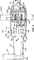
図3,4−8および17で分かるように、移動装置300は一般に本体部310と外側に延びるアダプター部610とから構成される。本体部310は上部ハウジング312と内部プレート314,316と下部ハウジング318とから構成される。図3でよく分かるように、上部ハウジング312、内部プレート314,316および下部ハウジング318は内部プレート314,316がハウジング312,318の間に捕捉されるように
共に取り付けられる寸法にされる。ハンドル/アクチュエータアセンブリ410(図13に図示される)および一対の顎/ラッチアセンブリ510A,510B(510Bは図14に図示される)は内部プレート314,316の間で本体部310内に捕捉される寸法にされる。
As can be seen in FIGS. 3, 4-8 and 17, the moving
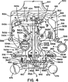
ハウジング312,318および内部プレート314,316がその間に配置されたハンドル/アクチュエータアセンブリ410および顎/ラッチアセンブリ510A,510Bとともに組み立てられると、本体部310は図4に示すように対向する2つの支柱受けレセスまたは開口320A,320Bを規定する。支柱受けレセス320A,320Bは以下詳細に述べるように、移動装置300が支柱150、250に固定されるような支柱150または250を受ける寸法にされる。
When the
図1でよく分かるように、上部および下部ハウジング312,318および内部プレート314,316は、組み立てられたとき、本体部310が支柱受けレセス320A,320Bの縁を規定する一般にU型の鍔部322A,322Bを含むように形成される。鍔部322A,322Bは本体部310から外側に延びて一般にU型の支柱受けレセス320A,320Bを規定する。
As can be seen in FIG. 1, the upper and
ハウジング312,318は本体部310のU型鍔322A,322Bをほぼ規定する外側に延びる領域を含む。図17でよく分かるように、スロット328が各鍔322A,322Bの内面の縁近辺に沿って形成される。スロット328は、図16でよく分かるように、U型ガイド332を受ける寸法にされる。
The
図17でよく分かるように、ハウジング312,318内の各支柱受けレセス320A,320B内に空所342が形成される。空所342は各支柱受けレセス320A,320Bの内側縁に沿って形成され、図15および17でよく分かるようにパッド344を受ける寸法にされる。実施形態に示すように、各パッド344は一般にU型に形成され、その一方側に沿って間隔を置いたリブ344aが含まれる。パッド344は強くて弾力のあるポリマーで形成されるのが好ましく、ハウジング312,318の空所342内に捕捉される寸法にされ、パッド上のリブ344aは図3に示すように本体部310の支柱受けレセス320A,320Bの内面に沿って延びる。
As can be clearly seen in FIG. 17,
内部プレート314,316はほぼ同一である。各内部プレート314,316は平板状の外面314a,316aおよび輪郭を示す内面314b、316bを含む。内部プレート314,316を上部および下部ハウジング312,318と組み立てたとき、外面314a,316aは本体部310の中心の外側に向く。換言すれば、内部プレート314,316の外面314a,316aはそれぞれ上部ハウジング312および下部ハウジング318に対向して係合する。輪郭を示す内面314b,316bはハンドル/アクチュエータアセンブリ410および顎/ラッチアセンブリ510A,510Bを受けるように形成される。
The
図17に、上部ハウジング312に対して配置された内部プレート314の外面314aが示され、また下部ハウジング318に対して配置された内部プレート316の輪郭面316bが示される。各内部プレート314,316はその一端に細長い長方形スロット352を含み、プレートの側部で外側に延びる2つのノッチまたは開口354は支柱受けレセス320A,320Bの一部を規定する。
FIG. 17 shows the
図17でよく分かるようにスロット362、364が各内部プレート314,316の正面の端面に形成される。スロット362,364は長方形形状であり、図17にXで示す中心軸の回りに対称な円形通路に沿って延びる。以下に詳述するように、内部プレート314,316を一緒に組み立てると、それぞれの内部プレート314,316のスロット362、364は内部プレート314,316の正面の端面を通るそれぞれ符号362Pで示す外側円形通路および符号364Pで示す内側円通路に整合して規定する。
As can be clearly seen in FIG. 17,
次に図13でハンドル/アクチュエータアセンブリ410がよく理解できる。ハンドル/アクチュエータアセンブリ410には細長いシャフト412が含まれる。シャフト412の一端にアクチュエータ422が装着される。図9−12でよく分かるように、アクチュエータ422はフランジスリーブ418に取り付けられ、フランジスリーブはシャフト412に取り付けられる。実施形態に示すように、アクチュエータ422はカム要素である。カム要素は一般に腎臓形状とし、図9−12でよく分かるように、カム面424にカム面の主要部となる円形部424aを規定する。実施形態に示すように、カム面424の円形部424aはシャフト412の回りに一定の半径で180度の範囲で延びる。カム面424にはまた移行部424bが含まれる。移行部424bは円形部424aの反対側に形成され、谷部424cに向って集まる。
Next, the handle /
図13でよく分かるように、第2フランジスリーブ432がシャフト412の他端に配置される。端部キャップ442が、第2フランジスリーブ432からキャップ442に達する取付け具434によって第2フランジスリーブ432のフランジ部分に装着される。キャップ442と第2フランジスリーブ432のフランジ部分との間に中間プレート452が捕捉される。中間プレート452には円形ディスク部分452aおよびディスク部分452aの一方側に延びる円筒壁部分452bが含まれる。実施形態に示すように中間プレート452は円筒壁部分452bがアクチュエータ422の方向に延びるように配置される。円筒壁部分452bはシャフト412の回りに対称である。図13でよく分かるように、円筒壁452bには対向するスロット456が形成される。間隔のある一対のタブ462が中間プレート452の面からアクチュエータの方向に延びる。タブ462はシャフト412の軸の反対側に対称に間隔を保ち、円筒壁452b内、すなわち、円筒壁452bとシャフト軸との間に配置される。ハンドルバー472が端部キャップ442の端面を横切って取り付けられる。ハンドルバー472は端部キャップ442を越えて延びる寸法にされる。グリップがハンドルバー472の先端に装着される。実施形態に示すように、グリップ474は球状であり、一方グリップ476は円形ディスク状である。
As can be clearly seen in FIG. 13, a
ハンドル/アクチュエータアセンブリ410は内部プレート314、316間に捕捉される寸法にされる。図17でよく分かるように、内部プレート314,316を1つに組み立てるとき、シャフト412を受ける寸法にされた円筒通路が形成されるように、内部プレート314,316の輪郭面314b、316bに細長い円筒溝372が形成される。ハンドル/アクチェータアセンブリ410と内部プレート314,316の寸法は、シャフト412を内部プレート314,316の円筒溝372内に捕捉したときアクチェータ422が内部プレート314,316の長方形スロット352に位置して、ここから飛び出すようにされる。
Handle /
図4−8でよく分かるように、ハンドル/アクチュエータアセンブリ410を内部プレート314,316の間に捕捉したとき、中間プレート452の円筒壁部分452bは内部プレート314,316の端面の外側円通路362Pを規定するスロット362内に配置され、タブ462は内部プレート314,316の端面のスロット364で規定された円形通路364P内で移動できるよう位置する。
As best seen in FIGS. 4-8, when the handle /
内部プレート314,316はまた顎/ラッチアセンブリ510A,510Bをその間に捕捉するように設計される。顎/ラッチアセンブリ510A,510Bはほぼ同一であるので、顎/ラッチアセンブリ510Bのみを詳述するが、このような記載は同じく顎/ラッチアセンブリ510Aにも適用される。顎/ラッチアセンブリ510Bの記載において、部品は参照符号と添え字Bで記載する。図面では顎/ラッチアセンブリ510Aの部品は同様に参照符号と添え字Aを付す。
次に図14を参照すると、顎/ラッチアセンブリ510Bがよく理解できる。顎/ラッチアセンブリ510Bは顎要素512Bとラッチ要素552Bとで構成される。顎面514Bが顎要素512Bの一方の縁に沿って形成される。カムフォロワ516Bが顎要素512Bの他端に装着される。実施形態ではカムフォロワ516Bは顎要素512Bの端部のノッチ522B内に装着されたローラである。ローラ516Bは、図4−8でよく分かるように、ノッチ522Bを通る顎要素512B内に延びる。円筒穴532Bが顎要素512Bを貫通して顎面514Bに達する。穴532Bには調整ネジ534Bを受ける内ネジが含まれる。実施形態に示すように、顎要素512Bは比較的厚いプレート材料で形成され、顎要素512Bの上面および下面は平坦である。薄いスロット542Bが顎要素512Bの1つの縁に形成される。スロット542Bは顎要素512Bの平坦な面の間に配置され、顎要素512Bの平坦な面と共面である。
Referring now to FIG. 14, the jaw /
ラッチ要素552Bは第1端部554Bと第2端部556Bを有する細長い構造物である。図14に示すように、第1端部554Bは顎要素512Bのスロット542B内に受けられる寸法にされる。ラッチ要素の第1端部554Bは顎要素512Bの上面および下面に垂直に顎要素512Bを貫通する旋回ピン562Bによって顎要素512Bに旋回可能に結合される。図14に示すように、旋回ピン562Bの長さは顎要素512Bの厚さよりも大きく、そのため旋回ピン562Bの一部は顎要素512Bの上面を越え、顎要素512Bの下面を越えて延びる。
The
ラッチ要素552Bの第2端部556Bは一般にL形状をなし、ラッチ要素552Bの一方側に延びる指566Bを規定する。ラッチ要素552Bの第1端部554Bと第2端部556Bとの間に輪郭面572Bが形成される。以下に詳述するように輪郭面572Bは円形に湾曲して支柱150または250に係合する。ラッチ要素552Bの輪郭面572Bと第2端部との間で、タブ574Bがラッチ要素552Bの一方側に延びる。図14でよく分かるように、ラッチ要素552Bの他方の縁に突起576Bを形成するためノッチが形成される。
The
顎/ラッチアセンブリ510Bは本体部310の内部プレート314,316の間に配置されるように設計される。図17でよく分かるように、旋回ピン562Bの延長部分は内部プレート314,316の穴開口内に受けられる。内部プレート314,316は顎要素512Bを受けるためレセスが形成され、そのレセスによって内部プレート314,316間に規定された空所内で旋回ピン562Bの軸の回りに顎要素512Bが動作できる。
The jaw /
顎付勢要素582Bが顎要素512Bに取り付けられ、以下に詳述するように顎要素512Bを「非クランプ位置」の方向に付勢する。実施形態では、図4−8でよく分かるように、顎付勢要素582Bは一端が顎要素512Bの1つの縁に取り付けられた引張りバネである。付勢要素582Bの他端は内部プレート314,316の間に延びるピン584Bに取り付けられる。実施形態では、以下に詳述するように、顎付勢要素582Bは顎要素512Bのカムローラ516Bをハンドル/アクチュエータアセンブリ410の方向に付勢する。ラッチ付勢要素592Bがラッチ要素552Bに取り付けられる。図4−8でよく分かるように、ラッチ付勢要素592Bの一端はラッチ要素552Bの突起576Bに装着され、ラッチ付勢要素592の第2端部は内部プレート314,316間に延びるピン594Bに装着される。ラッチ付勢要素592Bはラッチ要素552Bがハンドル/アクチュエータアセンブリ410のシャフト412から離れる方向に付勢する。図4−8でよく分かるように、ラッチ付勢要素592Bおよびピン594Bは内部プレート314,316の内面に形成されたスロットまたは溝382内に配置される。各スロットまたは溝382は中心空所384に通じ、肩面386を規定する。圧縮バネ598Bが一般にラッチ付勢要素592Bと整合してラッチ付勢要素592Bの反対側に配置される。この点、圧縮バネ598Bは基本的にラッチ付勢要素592Bと一軸上に整列される。
A
上述したように、ハンドル/アクチュエータアセンブリ410および顎/ラッチアセンブリ510A,510Bは内部プレート314,316の間でその内面314a,316aに沿って形成された空所内に捕捉される寸法にされる。図4でよく分かるように、ハンドル/アクチュエータアセンブリ410のシャフト412は移動装置300の本体部310を貫通する中心軸Xを規定する。顎/ラッチアセンブリ510Aはハンドル/アクチュエータアセンブリ410の一方側に配置され、顎/ラッチアセンブリ510Bはハンドル/アクチュエータアセンブリ410の反対側に配置される。この点、それぞれの顎/ラッチアセンブリ510A,510Bはハンドル/アクチュエータアセンブリ410のシャフト412の軸Xに関して対称である。顎/ラッチアセンブリ510A,510Bはそれぞれ旋回ピン562A,562Bの回りに移動可能である。図9−12に示すように、顎要素512A,512Bはローラ516A,516Bがアクチュエータ422のカム面424に係合して作動できるような寸法にされる。
As described above, the handle /
図4でよく分かるように、アクチュエータ422のカム面424は、顎要素512A,512Bが旋回ピン562A,562Bの回りに旋回するときローラ516A,516Bがカム面に沿って転がるように丸められる。顎付勢要素582A,582Bの引張りバネは、顎要素512A,512Bのローラ516A,516Bがそれぞれカムアクチュエータ422の方向に付勢されて作動するように配置される。換言すれば、顎付勢要素582A,582Bは顎要素512A,512Bのローラ516A,516Bを付勢してアクチュエータ422のカム面424に係合させる。図4を参照すると、顎/ラッチアセンブリ510Aに取り付けられた顎付勢要素582Aは顎要素512Aを時計方向に付勢し、また顎/ラッチアセンブリ510Bに取り付けられた顎付勢要素582Bは顎要素512Bを反時計方向に付勢する。
As can be seen in FIG. 4, the
図4−8に示すように、顎/ラッチアセンブリ510A,510Bのラッチ要素552A,552Bはラッチ付勢要素592A,592Bによって外側方向、すなわちハンドル/アクチュエータアセンブリ410のシャフト412から離れる方向に付勢される。最も外側の位置では、ラッチ要素552Aはハウジング本体310の支柱受けレセス320A内まで延び、ラッチ要素552Bは支柱受けレセス320B内まで延び,輪郭面572A,572Bはそれぞれの支柱受け開口320A,320B内に延びる。図4に示すように、顎/ラッチアセンブリ510Bのラッチ要素552Bがこの位置にある場合は、圧縮バネ598Bはラッチ要素552Bに係合しない。
As shown in FIGS. 4-8, the
以下に詳述するように、ラッチ要素552A,552Bはハンドル/アクチュエータ410が一般に図3に示すように水平位置にあるときのみ最も外側の位置(ラッチ要素552Bに関して図4に示す)にあるものと想定できる。この位置で、ハンドルアクチュエータアセンブリ410のハンドルバー472は内部プレート314,316で規定された分割面にそって整合される。この点、ハンドルアクチュエータアセンブリ410の中間プレート452の位置は、中間プレート452の円筒壁部分452bのスロット456がラッチ要素552A,552Bが移動する面に整合する位置となる。その結果、ラッチ要素552A,552Bの第2端部556A,556Bの指566A,566Bは中間プレート452の円筒壁部分452bのスロット456を通して移動できる。図4はハンドル/アクチュエータアセンブリ410の円筒壁部分452bのスロット456内に配置された顎/ラッチアセンブリ510Bのラッチ要素552Bの指566Bを示す。この位置においてラッチ要素552Bはハンドル/アクチュエータアセンブリ410の軸Xから最も外側に離れた位置となる。図4に示すように、ラッチ付勢要素592A,592Bで生じる力によってラッチ要素552A,552Bの外縁は内部プレート314,316で規定された肩386に当接する。
As will be described in more detail below, the
ラッチ要素552A,552Bの動作範囲を図4に示すが、顎/ラッチアセンブリ510Aのラッチ要素552Aは最も内側の位置を示し、顎/ラッチアセンブリ510Bのラッチ要素552Bは最も外側の位置を示す。以下に詳述するように、ラッチ要素552Aまたは552Bは支柱150または250がラッチ要素でクランプされたとき最も内側の位置となり、ラッチ要素552Aまたは552Bが内部プレート314,316の肩386に当接したときラッチ要素552Aまたは552Bは最も外側の位置となる。
The operating range of the
上部と下部ハウジング312,318および中間プレート314,316はハンドル/アクチェータアセンブリ410および顎/ラッチアセンブリ510A,510Bをその間に配置してともに締め付ける寸法にされる。図4−8および17でよく分かるように、長い取付け具398が下部ハウジング318から中間プレート314,316を通って上部ハウジング312まで延びてそれぞれの構成部品をともに締め付ける。取付け具398の相対位置を図4−8に示す。
Upper and
次に図3および17にアダプター部610を示す。アダプター部610は本体部310に取り付けられて医療機器20を支持するように設計される。実施形態では、アダプター部610には平坦な端面612aを有する長い第1端部612が含まれる。長い端部612は本体部310の平坦な端部に合わせられて、孔616から本体部310まで延びる通常の取付け具614で取り付けられる。
Next, an
アダプター610には第1端部612と医療機器20を保持、支持するようにされた第2端部632とを結合するビーム状の中央本体部分622が含まれる。アダプター部610の第2端部632は支持フレーム22の柱34を受ける寸法にされた筒状スリーブである。図示しないセットネジのようなロック装置が柱34を固定するために第2端部632に設けられる。明細書を読み進めると理解できるが、アダプター部610の第2端部632は医療機器20を保持するのに他の形状のものも考えられる。
The
次に図4−12を参照して、さらに移動システム10および移動装置300の操作について本発明を述べる。移動装置300は支柱150,250などの支柱に取り付け、1つの支柱150,250から別の支柱150,250に移動可能なように設計される。以後、移動装置300を受けるべき支柱150,250は「受け支柱」と呼び、移動装置300を移動して開放するべき支柱を「渡し支柱」と呼ぶ。
Next, the present invention will be described with reference to FIGS. The moving
以下の記載から理解できるように、渡し支柱150,250が固定支持アセンブリ100または搬送車支持アセンブリ200であることもあり、受け支柱150,250が固定支持アセンブリ100または搬送車支持アセンブリ200であることもある。換言すれば、移動装置300は固定支持アセンブリ100と搬送車支持アセンブリ200との間を移動し、または2つの固定支持アセンブリ100の間または2つの搬送車支持アセンブリ200の間を移動することがある。
As can be understood from the following description, the transfer struts 150 and 250 may be the fixed
以下に詳述するように、移動装置300には、受け支柱150,250が適切な寸法の場合のみ、移動装置300を1つの支柱150,250から別の支柱150,250に移動させる一種の安全特徴が含まれる。さらに、移動装置が受け支柱150,250に固定、すなわちクランプされた時にのみ、移動装置300の渡し支柱150,250から受け支柱150,250への移動が行われる。その場合しか、移動装置300は渡し支柱150,250から開放、すなわち引き渡されない。
As will be described in detail below, the moving
さらにまた、受け支柱150,250が移動装置300の受け開口320A,320B内に配置されたときしか、渡し支柱150,250から受け支柱150,250に移動装置300の移動を開始するためのハンドル/アクチェータアセンブリ410の回転ができない。そのときのみハンドル/アクチェータアセンブリ410の回転が可能となる。
Furthermore, only when the receiving struts 150 and 250 are disposed in the receiving
次に、移動装置300の操作について、固定支持アセンブリ100の渡し支柱150から搬送車支持アセンブリ200の受け支柱250への移動装置300の移動に関して述べる。分かるように、2つの支柱150,250は類似の直径の金属管で構成されているので、それぞれの支柱150,250の位置は逆にしても移動装置300の操作またはその操作の以下の記載には影響を与えない。
Next, the operation of the moving
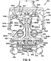
図4は顎要素512Aで移動装置300の受けレセス320Aにクランプされた渡し支柱150を示す。図4において、顎要素512Aは「クランプ位置」にあり、一方、顎/アセンブリ510Bの顎要素512Bは「非クランプ位置」にある。図9はアクチュエータシャフト412の軸Xに沿って見たときのアクチュエータ422の位置を示す。図4に示すように、渡し支柱150は移動装置300の支柱受けレセス320A内にあり、顎要素512Bの支柱受けレセス320Aの内面に対して位置が保持される。図4に示すように顎/ラッチアセンブリ510Aの顎要素512Aが「クランプ位置」にあるときのアクチェータ422の位置を図9に示す。図9に示すように、顎要素512Aのローラ516Aはシャフト412から離れた外側に押し付けられる。その結果、顎要素512Aの顎面514Aは渡し支柱150を押し付け、それによって渡し支柱150を支柱受けレセス320AのU型ガイド322およびパッド344に押し付ける。
FIG. 4 shows the
図4に示すように、渡し支柱150のクランプによって顎/ラッチアセンブリ510Aのラッチ要素552Aの圧縮バネ598Aを押し付けて、ラッチ要素552Aの端部556Aが内部プレート314,316の端面に形成された円通路362P,364Pを塞がない位置にする。また図4に示すように、顎/ラッチアセンブリ510Bのラッチ要素522Bはラッチ要素522Bの端部556Bが中間プレート452の円筒壁部分452bのスロット456内に配置される位置にある。この位置においてラッチ要素552Bはハンドル/アクチュエータ410の回転を阻止し、それによって顎/ラッチアセンブリ510の顎要素512Aが渡し支柱150から移動して開放することを阻止する。
As shown in FIG. 4, the clamp 624 of the jaw /
移動装置300を支柱150から支柱250に移動させるためには、支柱250が支柱受けレセス320B内に位置することが必要となる。図1に示すように、支柱150は自軸の回りに回転自在であるので、支柱150の軸の回りに移動装置300を回転させて支柱受けレセス320Bを再位置決めし、それによって支柱受けレセス320Bを支柱250に対して再位置決めする。
In order to move the moving
図5は、受け支柱250が移動装置300の支柱受けレセス320Bに位置したときの
移動装置300の内部構成部品の相対位置を示す。この点、移動装置300および受け支柱250は移動装置300の支柱受けレセス320B内に受け支柱250を位置するように互いに相対的に移動される。受け支柱150,250の整合ずれがわずかの場合は、支柱受けレセス320Bの上端、下端のガイド332が支柱受けレセス320Bに対する受け支柱150,250の整合を助けるので、受け支柱150,250は支柱受けレセス320B内に挿入できる。図5に示しように、受け支柱250が支柱受けレセス320Bに入ると、ラッチ要素552Bはアクチュエータシャフト412の方向に動かされる。言い換えれば、受け支柱250を支柱受けレセス320B内に位置させることで、ラッチ要素552Bのラッチ付勢要素592Bで生じた付勢力に打ち勝つために十分な力が与えられる。その結果、ラッチ要素552Bはハンドル/アクチェータアセンブリ410のシャフト412の方向に動き、ラッチ要素552Bの内縁が圧縮バネに接触する。圧縮バネ598Bは十分に大きな力で圧縮バネ598Bを圧縮するに必要な寸法にされる。言い換えれば、圧縮バネ598Bの反発力は受け支柱250とラッチ要素552Bの間の単なる接触または係合では解消されることはない。図5に示すように、ラッチ要素552Bはラッチ要素552Bの端部556Bが中間プレート452の円筒壁部分452bのスロット456から十分抜け出すまで移動する。ラッチ要素552Bの端部556Bが円筒壁部分452bのスロット452から取り除かれると、ハンドル/アクチュエータアセンブリ410のX軸回りの回転が可能となる。
FIG. 5 shows the relative positions of the internal components of the moving
受け支柱250が支柱受けレセス320B内にあって、ラッチ要素552Bが中間プレート452のスロット456から抜け出した状態において、ハンドル/アクチュエータアセンブリ410の回転が可能となる。図6は、ハンドル/アクチュエータアセンブリ410が図4に示す最初の位置から開始して回転中の移動装置300の内部構成部品の位置を示す。ハンドル/アクチュエータアセンブリ410の時計方向の回転によってアクチュエータ422は図10に示す位置に移動する。アクチュエータ422の回転によって顎要素512Bは、それに関連するローラ516Bがカム面424の移行部424bに沿って回転するので、旋回ピン562Bの回りに時計方向に旋回する。顎要素512Aは、それに関連するローラ516Aがカム面424の円形部424aに沿って回転し続けるので、ロック位置に留まる。図6に示しよう、ラッチ要素552Bはほぼ同じ位置に留まり、その内縁は圧縮バネ598Bに対向する。
The handle /
次に図7および11を参照すると、ハンドル/アクチュエータアセンブリ410は時計方向に回転を続けるので、アクチュエータ422は図11に示す位置に達する。この位置において、2つのローラ516a,516Bはアクチュエータ422のカム面424の円形部424aに乗って配置される。図7に示すように、顎要素512Bは受け支柱250に係合し、受け支柱250をラッチ要素552Bの輪郭面572Bに押し付ける。カム面424とローラ516Bの配置で得られた機構上の利点によって、顎要素512Bは受け支柱250を十分な力でラッチ要素552Bに押し付けて圧縮バネ598Bを圧縮する。言い換えれば、顎512Bの幾何学的形状、旋回ピン562Bの位置およびローラ516Bの位置に加えて、カム面424とローラ516Bの配置で得られた機構上の利点は、受け支柱250によってラッチ要素552Bを圧縮バネ598Bに押し付けてその圧縮力に打ち勝つのに十分な力を付与することにある。図7に示すように、この位置では、ラッチ要素552Bの端部556Bは最も内側の位置に移動している。この位置では、ラッチ要素552Bの端部556Bが内部プレート314,316の端面に形成された内側円通路364Pを塞ぐことはない。その結果、ハンドル/アクチュエータアセンブリ410はさらに回転が可能となり、中間プレート452の内面から延びるタブ462は内部プレート314,316の端面に沿って形成された内側円通路364Pを通過することが可能となる。
7 and 11, as the handle /
各ラッチ要素552A,552Bは基本的に、ハンドルバー472の運動、すなわち回転を規制し、アクチュエータの運動を規制するロック要素を規定する。実施形態では、各
ラッチ要素552A,552Bは3つの位置を有するロック要素を規定する。例えば、ラッチ要素552Bを使用して、図4に示す第1の位置でラッチ要素552Bはハンドルバー472とアクチュエータ422の運動を抑制するロック要素として作用する。
Each of the
図6に示す第2の位置においては、ラッチ要素552Bはロック要素として作用し、ハンドルレバー472とアクチュエータ422の運動を制限する。この第2の位置ではラッチ要素552Bはアクチュエータ422に十分な運動を与えて2つの顎要素512A,512Bをクランプ位置に移動させるが、移動装置300を渡し支柱150から受け支柱250に完全に移動させるさらなる運動は抑制する。
In the second position shown in FIG. 6, the
図7に示す第3の位置においては、ラッチ要素552Bはハンドルバー472の回転とアクチュエータ422の運動を完全に可能にする位置にあり、アクチュエータ422は第1のアクチュエータ位置(図9に示す)から第2のアクチュエータ位置(図12に示す)まで移動することが可能となる。アクチュエータ422が第1のアクチュエータ位置にあるときは、移動装置300は第1支柱、すなわち渡し支柱150に取り付けられている。
アクチュエータ422が第2のアクチュエータ位置にあるときは、移動装置300は第2支柱、すなわち受け支柱250に取り付けられている。実施形態では、ハンドルバー472を180度移動させると、アクチュエータ422は第1のアクチュエータ位置から第2のアクチュエータ位置に移動する。ハンドルバー472とアクチュエータ422の位置に応じて移動装置300は一方の支柱150または250に取り付けられ、もう一方の支柱は開放される。移動装置には、ハンドルバー472が図4および8に示す位置にあるとき、識別する位置もどり止め(図示しない)が含まれるのが好ましい。
In the third position shown in FIG. 7, the
When the
顎要素512Bで受け支柱250はラッチ要素に押し付けられるので、ラッチ要素は十分に移動してハンドル/アクチュエータアセンブリ410がさらに回転できる。図8および12はハンドルバー472が完全に180度回転したときのハンドル/アクチュエータアセンブリ410とアクチュエータとの相対位置を示す。図12に示すように、顎要素512Bに関連するローラ516Bはカム面424の円形部424aに沿って配置されるので、顎要素512Bは受け支柱250に対するクランプ位置に維持される。また図12に示すように、顎要素512Aに関連するローラ516Aはカム面424も谷部424c内の位置に移動する。この位置において、顎要素512Aに結合された顎付勢要素582Aによって顎要素512Aは旋回ピン562Aの回りに時計方向に回転して、渡し支柱150を開放する。顎/ラッチアセンブリ510Aに関連するラッチ要素552Aはシャフト412の中心軸から最も外側に離れた位置に移動する。この位置において、ラッチ要素552Aの端部556Aは中間プレート452の円筒壁部分452bのスロット456内に配置されるので、ハンドル/アクチュエータアセンブリ410のさらなる回転が抑制される。このように、受け支柱250は移動装置内に確実にクランプされる。移動装置300およびそこに装着された関連する医療装置20は受け支柱250に固定されることになり、それによって支持される。以上に述べたように、移動装置300が受け支柱150,250に固定取り付けられ、すなわちクランプされるまでは、移動装置300の渡し支柱150,250から受け支柱150,250への移動は起こりえない。
Because the receiving
移動装置300は支柱250に対して回転移動しないように設計される。しかし、前述したように、支柱250はブラケット232およびベッド212に対して鉛直軸の回りに回転可能である。したがって、移動装置300および支柱250は移動装置300およびそこに装着された医療機器20をベッド212の隅付近の種々の位置に移動させるため、支柱250の軸の回りに回転できる。言い換えれば、医療機器20は一般に支柱250の軸を中心点とする円通路に沿って移動できる。同じやり方で、移動装置300が支柱150に装着される場合は、移動装置300に装着された機器20は支柱150の軸の回りの円通路に沿って移動できる。
The moving
移動装置300を不適切な寸法の支柱に取り付けようと試みられた場合は、移動装置300の形態によって安全機構が働く。この点、移動装置300を受ける支柱が小さ過ぎると、小さい方の支柱のクランプではラッチ要素552Aまたは552Bが十分に移動しないので、ラッチ要素552Aまたは552Bの端部556Aまたは556Bが内部プレート314,316の端面に形成された内側通路364Pをクリアしない。その結果、中間プレート452のタブ462は内側円通路364Pを通って回転することができなくなり、ハンドル/アクチュエータアセンブリ410のさらなる回転が抑制される。さらなる回転が抑制されるので、アクチュエータ422は図11に示す位置に留まり、2つの顎要素512Aおよび顎要素512Bはともにクランプ位置になる。
If an attempt is made to attach the
移動装置300を過大寸法の支柱に取り付けようとすれば、このような支柱への移動装置300の移動は同様に阻止される。この点、課題寸法の支柱、すなわち、より大きい直径を有する支柱は支柱受けレセス320A,320Bの上端および下端に位置するガイド332に入らない。図16Bは符号750を付した過大寸法の支柱が支柱受けレセス320Aに配置された状態を示す。図示するように、ガイド332は細長いレセス329Aの所定の巾を規定する間隔のあるアーム332a,332bを有する。ガイド332のアーム332a,332b間の間隔でそこに挿入できる支柱の寸法が制限される。図16Aに示すように適当な直径(またはより小さい)の支柱のみが支柱受けレセス320A,320Bで受けられる。ガイド332によって、より大きな直径の支柱が支柱受けレセス320A,320Bに入ることが阻止される。その結果、ラッチ要素552Aの必要な運動が阻止され、ハンドルバー472は図4に示す最初の位置から動かすことができない。
If the moving
このように、上記の構造によって不適当な寸法の支柱が移動装置300に使用されることが阻止される。不適当な寸法の支柱、すなわち、より小さい直径の支柱であれば、支柱受けレセス320Aまたは320B内に配置された支柱に対する顎要素512Aまたは512Bのクランプ力が減少する。
Thus, the structure described above prevents the improperly sized struts from being used in the moving
このように、移動装置300によって医療機器20の渡し支柱150から受け支柱250への移動およびその逆の移動が実施できる。移動装置300を1つの支柱から別の支柱へ移動させるのに移動装置300の鉛直方向の位置決めが必要でないことは注目される。この点、移動装置300は一般に水平方向に移動可能であり、1つの支柱から別の支柱に移動するとき同一の鉛直位置、すなわち、高さを維持する。さらに、図示するように、移動装置300は支柱150,250の長さに沿っていずれの箇所にも取り付け可能であることに注目される。このように、支柱150,250の鉛直方向の再位置決めは同様に必要でない。上述したように、支柱150、250は固定支持アセンブリ100または搬送車支持アセンブリ200の一部である。
As described above, the
このように、本発明は医療機器20を1つの支柱150,250から別の支柱150,250に水平移動させる移動装置300を提供する。移動装置300には故障で移動装置300が支柱150,250から開放されるのを阻止し、また過小または過大寸法の支柱が移動装置300に挿入されるのを阻止する安全特徴が含まれる。
Thus, the present invention provides a moving
以上述べたことは本発明の特別の実施形態である。この実施形態は例示のためにのみ記載したものであり、発明の精神および範囲から逸脱することなく当分野の専門家には様々な変更が行われることが理解される。システム100および移動装置300は医療環境に関して記載されているが、本発明はこのような適用には限定されない。特許請求の範囲またはこれの均等な範囲内である限り、このようなすべての変更も含まれるものである。
What has been described above is a specific embodiment of the present invention. This embodiment has been described by way of example only, and it will be understood that various changes may be made by those skilled in the art without departing from the spirit and scope of the invention. Although
本発明は一定の部分および部分の配置において具体的な形態をとり、その好ましい実施形態は明細書で詳細に記述し、かつ一部を形成する付帯する図面で説明する。
Claims (13)
第1の支柱受けレセスと第2の支柱受けレセスを有するハウジングと、ハウジングはそれぞれが渡し支柱又は受け支柱を受ける寸法にされた前記第1及び第2の支柱受けレセスを備え、
前記ハウジングに装着された第1の顎要素と、
前記ハウジングに装着された第2の顎要素と
を備え、
前記第1の顎要素は前記第1の支柱受けレセスの対応する位置に置かれ、前記第1の顎要素が前記渡し支柱を前記第1の支柱受けレセスにクランプするクランプ位置と、前記渡し支柱が前記第1の支柱受けレセス内外に対して移動可能である非クランプ位置との間で移動可能であり、
前記第2の顎要素は前記第2の支柱受けレセスの対応する位置に置かれ、前記第2の顎要素が前記受け支柱を前記第2の支柱受けレセスにクランプするクランプ位置と、前記受け支柱が前記第2の支柱受けレセス内外に対して移動可能である非クランプ位置との間で移動可能であり、
さらに、前記クランプ位置と前記非クランプ位置との間で前記第1及び第2の顎要素のそれぞれを回転させるため前記第1及び第2の顎要素にローラを介して係合されたアクチュエータを備え、
前記第1の顎要素はクランプ位置にあり、前記アクチュエータが第1のアクチュエータ位置(第1の顎要素512Aがクランプ位置に第2の顎要素512Bが非クランプ位置になるアクチュエータの位置)にあるとき、前記第2の顎要素は非クランプ位置にあり、
前記第2の顎要素はクランプ位置にあり、前記アクチュエータが第2のアクチュエータ位置(第1の顎要素512Aが非クランプ位置に第2の顎要素512Bがクランプ位置になるアクチュエータの位置)にあるとき、前記第1の顎要素は非クランプ位置にある
事を特徴とする移動装置。 A device for supporting a medical device used in caring for a patient, a transfer strut attached to a fixed support assembly, and a transfer device for passing the device between receiving struts ,
A housing having a first strut receiving recess and a second strut receiving recess , the housing comprising the first and second strut receiving recesses each dimensioned to receive a transfer strut or receiving strut;
A first jaw element mounted on the housing;
A second jaw element mounted on the housing,
It said first jaw element is placed in the corresponding position of the first strut receiving recesses, and a clamping position in which said first jaw element clamping the pass strut to the first strut receiving recess, the passing strut Is movable between an unclamped position that is movable relative to the inside and outside of the first strut receiving recess,
Said second jaw element is placed in the corresponding position of the second support column receiving recess, a clamping position in which said second jaw elements to clamp said received strut to the second strut receiving recess, the receiving post Is movable between an unclamped position that is movable relative to the inside and outside of the second strut receiving recess,
Further comprising an actuator engaging through rollers to said first and second jaw elements for rotating each of said first and second jaw elements between said non-clamping position and the clamping position ,
When the first jaw element is in the clamp position and the actuator is in the first actuator position (the position of the actuator where the first jaw element 512A is in the clamp position and the second jaw element 512B is in the unclamped position) The second jaw element is in an unclamped position;
When the second jaw element is in the clamp position and the actuator is in the second actuator position (the position of the actuator where the first jaw element 512A is in the unclamped position and the second jaw element 512B is in the clamped position) The first jaw element is in an unclamped position
A mobile device characterized by things .
前記第1のアクチュエータ位置と前記第2のアクチュエータ位置との間で前記アクチュエータの回転を制限する第2の位置と、
前記第1のアクチュエータ位置と前記第2のアクチュエータ位置との間で前記アクチュエータの回転を自由にする第3の位置と
を有するロック要素として作用するラッチ要素をさらに備えた、請求項1に記載の移動装置。A first position for preventing rotation of the actuator;
And a second position for restricting rotation of said actuator between said second actuator position and the first actuator position,
Wherein further comprising a latching element which acts as a locking element and a third position to free the rotation of the actuator between a first actuator position and the second actuator position, according to claim 1 Mobile equipment.
Applications Claiming Priority (2)
| Application Number | Priority Date | Filing Date | Title |
|---|---|---|---|
| US67831905P | 2005-05-06 | 2005-05-06 | |
| PCT/US2006/017572 WO2006121947A2 (en) | 2005-05-06 | 2006-05-05 | Transfer system and transfer device |
Publications (2)
| Publication Number | Publication Date |
|---|---|
| JP2008539902A JP2008539902A (en) | 2008-11-20 |
| JP4615047B2 true JP4615047B2 (en) | 2011-01-19 |
Family
ID=37397166
Family Applications (1)
| Application Number | Title | Priority Date | Filing Date |
|---|---|---|---|
| JP2008510296A Expired - Fee Related JP4615047B2 (en) | 2005-05-06 | 2006-05-05 | Moving system and moving device |
Country Status (14)
| Country | Link |
|---|---|
| US (1) | US7789361B2 (en) |
| EP (1) | EP1876926B1 (en) |
| JP (1) | JP4615047B2 (en) |
| KR (1) | KR20080002927A (en) |
| CN (1) | CN101170930B (en) |
| AT (1) | ATE531353T1 (en) |
| AU (1) | AU2006244365B2 (en) |
| BR (1) | BRPI0612460A2 (en) |
| CA (1) | CA2607625C (en) |
| ES (1) | ES2374836T3 (en) |
| IL (1) | IL186897A0 (en) |
| MX (1) | MX2007013781A (en) |
| TW (1) | TW200701968A (en) |
| WO (1) | WO2006121947A2 (en) |
Families Citing this family (29)
| Publication number | Priority date | Publication date | Assignee | Title |
|---|---|---|---|---|
| US7314200B2 (en) * | 2004-05-13 | 2008-01-01 | American Sterilizer Company | Support and transport system for medical apparatus |
| US7637464B2 (en) * | 2006-01-19 | 2009-12-29 | Hill-Rom Services, Inc. | Patient support with mobile IV stand transport handle |
| US8336839B2 (en) * | 2006-09-28 | 2012-12-25 | Stryker Corporation | Medical equipment transfer arrangement |
| US7798456B2 (en) * | 2007-08-21 | 2010-09-21 | Hill-Rom Services, Inc. | Transferable patient care equipment support |
| US7748672B2 (en) | 2007-09-07 | 2010-07-06 | Hill-Rom Services, Inc. | Transferable patient care equipment support |
| WO2009132458A1 (en) * | 2008-05-01 | 2009-11-05 | Vesco Tijanic | Connector and medical device system incorporating same |
| CA2723832A1 (en) * | 2008-05-08 | 2009-11-12 | Edward Masionis | Portable life support apparatus ventilator |
| US8167259B2 (en) * | 2009-04-06 | 2012-05-01 | Baxter International Inc. | Rapid attach and release clamps |
| US20110064548A1 (en) * | 2009-09-17 | 2011-03-17 | Acist Medical Systems, Inc. | Apparatus and methods for medical device transfer |
| US8205847B2 (en) * | 2009-11-06 | 2012-06-26 | American Sterilizer Company | Connection system for mounting a device onto a support arm |
| GB201006868D0 (en) * | 2010-04-23 | 2010-06-09 | Whiteman Geoffrey | Drip stand extension |
| US9528536B2 (en) | 2010-05-10 | 2016-12-27 | Nexxspan Healthcare, Llc | Secure equipment transfer system |
| US9404616B2 (en) | 2010-05-10 | 2016-08-02 | Nexxspan Healthcare, Llc | Secure equipment transfer system |
| CN101972501B (en) * | 2010-10-18 | 2012-09-12 | 迈柯唯医疗设备(苏州)有限公司 | Intelligent closed-loop identification, resetting and feedback device |
| US8733719B2 (en) | 2010-11-12 | 2014-05-27 | Wildcard Enterprises Llc | Method and apparatus for use in management of medical intravenous pole assemblies |
| GB201116632D0 (en) * | 2011-09-27 | 2011-11-09 | Barrett Michael | Connector |
| WO2014072196A1 (en) * | 2012-11-09 | 2014-05-15 | Fresenius Vial Sas | Locking system for locking a medical device |
| US9746268B2 (en) | 2012-11-13 | 2017-08-29 | Allan W. Antell | Shooting rests and pole assemblies |
| AU2013404103B2 (en) * | 2013-10-28 | 2017-10-19 | Nexxspan Healthcare, Llc | Secure equipment transfer system |
| US9511185B2 (en) * | 2014-04-18 | 2016-12-06 | Regents Of The University Of Minnesota | Intravenous line lifter devices, systems and methods |
| AU2015391040B2 (en) * | 2015-04-14 | 2021-02-04 | Nexxspan Healthcare, Llc | Secure equipment transfer system |
| US9585806B2 (en) | 2015-06-11 | 2017-03-07 | Acist Medical Systems, Inc. | Variable rate bedrail clamp |
| US10258524B2 (en) | 2016-02-22 | 2019-04-16 | Nexxspan Healthcare, Llc | Transfer system with sacrificial mechanical link |
| US10258424B2 (en) | 2016-02-22 | 2019-04-16 | Nexxspan Healthcare, Llc | Sacrificial mechanical link |
| CN106985608A (en) * | 2017-04-14 | 2017-07-28 | 常州市吉庆机电有限公司 | A kind of universal wheel |
| CN108066845B (en) * | 2018-02-09 | 2021-02-26 | 刘学智 | Clinical treatment device that uses of department of general surgery |
| CA3153007A1 (en) | 2019-10-08 | 2021-04-15 | Alexander Bally | Transfer device docking indicator |
| EP3961081A1 (en) * | 2020-08-31 | 2022-03-02 | Active Cues B.V. | Ceiling mount |
| JP7445580B2 (en) | 2020-10-16 | 2024-03-07 | パラマウントベッド株式会社 | Pole holder set and bed device |
Family Cites Families (49)
| Publication number | Priority date | Publication date | Assignee | Title |
|---|---|---|---|---|
| US1774775A (en) * | 1929-05-09 | 1930-09-02 | Jr John A Weitz | Bracket for electric lights and flash lights |
| US2711300A (en) * | 1951-04-09 | 1955-06-21 | Nettie Burleson | Support for a container from which liquid is administered to a patient |
| US2876027A (en) * | 1957-02-26 | 1959-03-03 | William B Sulmonetti | Locking swivel type clamp assembly |
| US3385545A (en) * | 1966-02-09 | 1968-05-28 | Robert P. Patton | Conduit hanging apparatus |
| US3463440A (en) * | 1967-05-01 | 1969-08-26 | Arthur A Libby Jr | Reflective panels for use with lawn furniture and the like |
| US4572536A (en) * | 1983-05-26 | 1986-02-25 | Doughty Val J | I V Pole interconnection coupling |
| US4632221A (en) * | 1984-06-18 | 1986-12-30 | Stanford Joseph S | Bracing clamp for shoring structures |
| US4666111A (en) * | 1985-11-14 | 1987-05-19 | Robert Schuler | Holder for IV tube |
| US4795122A (en) * | 1986-07-15 | 1989-01-03 | Cleveland Clinic Foundation | Patient equipment transport and support system |
| US4893810A (en) * | 1986-07-21 | 1990-01-16 | Lee Scott H | Quick release collar |
| US4742981A (en) * | 1987-02-19 | 1988-05-10 | Maurice Converse | Surgical support system |
| US4832299A (en) * | 1987-12-04 | 1989-05-23 | Pacesetter Infusion, Ltd. | Clamp fixture |
| US5236162A (en) * | 1988-02-09 | 1993-08-17 | Desjardins Wallace H | Pump support system |
| US4844397A (en) * | 1988-06-27 | 1989-07-04 | C. R. Bard, Inc. | Intravenous pole clamp |
| US4945592A (en) * | 1988-09-30 | 1990-08-07 | The General Hospital Corporation | Transport system for portable patient care apparatus |
| CA2085011A1 (en) * | 1991-04-23 | 1992-10-24 | Friedhelm Kreuzer | Transportable medical apparatus in particular infusion supply apparatus |
| US5135191A (en) * | 1991-05-09 | 1992-08-04 | Jagco Corporation | Medical support system |
| US5344169A (en) * | 1992-01-27 | 1994-09-06 | Pryor Products | Multi-pole support stand |
| US5366191A (en) * | 1992-02-19 | 1994-11-22 | Joseph Bekanich | Support apparatus for a patient infusion device |
| DE9210979U1 (en) | 1992-08-17 | 1992-10-29 | Kreuzer Gmbh + Co Ohg, 8039 Puchheim, De | |
| CA2147158A1 (en) * | 1992-10-15 | 1994-04-28 | Robert Paul Williams | Intravenous delivery system |
| US5319816A (en) * | 1992-12-07 | 1994-06-14 | Hill-Rom Company, Inc. | IV rack transferrable from an IV stand to a hospital bed |
| US5355539A (en) * | 1993-01-19 | 1994-10-18 | St. Francis Research Institute | Clamp for interconnecting a free standing, wheeled intravenous pole with a mobile gurney |
| US5358205A (en) * | 1993-04-16 | 1994-10-25 | Starkey Douglas G | Device to connect I.V. pole and patient support |
| US5458305A (en) * | 1993-05-17 | 1995-10-17 | Woodward; John | Portable intravenous support stand |
| US5374074A (en) * | 1993-06-25 | 1994-12-20 | Smith; Sidney | Apparatus for attaching intravenous infusion poles to foldable wheelchairs |
| DE4335779C1 (en) * | 1993-10-20 | 1995-04-06 | Daimler Benz Ag | Press fit |
| US5482239A (en) * | 1994-09-12 | 1996-01-09 | Smith; K. C. | Portable attachment bar for attaching an intravenous container support apparatus to a patient transportation apparatus |
| US5588166A (en) * | 1995-01-04 | 1996-12-31 | Burnett; John | Medical attachment device |
| US5655741A (en) | 1995-03-16 | 1997-08-12 | Liebel-Flarsheim Company | Pivotal instrument support apparatus |
| US5898961A (en) * | 1995-06-07 | 1999-05-04 | Hill-Rom, Inc. | Mobile support unit and attachment mechanism for patient transport device |
| GB2312234B (en) * | 1996-04-17 | 2000-07-19 | Baxter Int | Medical device clamp |
| ES1034279U (en) * | 1996-05-30 | 1996-12-16 | Telefonica Nacional Espana Co | Multi-position television monitor stand |
| CN2259909Y (en) * | 1996-09-09 | 1997-08-20 | 佟亚莉 | Moveable frame for infusion |
| US6725483B2 (en) * | 1997-01-31 | 2004-04-27 | Hill-Rom Services, Inc. | Apparatus and method for upgrading a hospital room |
| US5987670A (en) * | 1998-04-23 | 1999-11-23 | The General Hospital Corporation | Medical equipment transport system |
| US6179260B1 (en) * | 1998-06-10 | 2001-01-30 | N. Sean Ohanian | Device for coupling an IV stand to a patient transport |
| US6079678A (en) * | 1998-10-22 | 2000-06-27 | Schott; Jeffery C. | Intravenous stand support assembly |
| US6382576B1 (en) * | 1999-06-08 | 2002-05-07 | Hill-Rom Services, Inc. | Clamping apparatus |
| US6585206B2 (en) * | 2000-06-05 | 2003-07-01 | Hill-Rom Services, Inc. | Medical accessory support |
| US6786302B2 (en) * | 2002-02-20 | 2004-09-07 | National University Of Singapore | Triple coupler for flexible scaffold system |
| US20040104321A1 (en) * | 2002-08-06 | 2004-06-03 | Marsolais Thomas R. | Adjustable connector for I.V. poles and medical devices |
| CA2517889A1 (en) * | 2003-03-18 | 2004-09-30 | Hill-Rom Services, Inc. | Patient care equipment management system |
| WO2005037163A2 (en) | 2003-10-13 | 2005-04-28 | Hill-Rom Services, Inc. | Transferable patient care equipment support |
| US7090181B2 (en) * | 2003-10-31 | 2006-08-15 | Gamber Johnson Llc | Ball and socket mounting assembly |
| US7766313B2 (en) * | 2003-11-12 | 2010-08-03 | Amarillo Hardware Company | Spring clamp system |
| US6969031B2 (en) * | 2003-12-02 | 2005-11-29 | Cari Lynn Ugent | Adjustable movable IV stand |
| US7314200B2 (en) * | 2004-05-13 | 2008-01-01 | American Sterilizer Company | Support and transport system for medical apparatus |
| US7884735B2 (en) | 2005-02-11 | 2011-02-08 | Hill-Rom Services, Inc. | Transferable patient care equipment support |
-
2006
- 2006-05-02 TW TW095115657A patent/TW200701968A/en unknown
- 2006-05-05 AT AT06759237T patent/ATE531353T1/en active
- 2006-05-05 BR BRPI0612460-7A patent/BRPI0612460A2/en not_active Application Discontinuation
- 2006-05-05 CN CN2006800155260A patent/CN101170930B/en not_active Expired - Fee Related
- 2006-05-05 US US11/429,332 patent/US7789361B2/en not_active Expired - Fee Related
- 2006-05-05 KR KR1020077025623A patent/KR20080002927A/en not_active Application Discontinuation
- 2006-05-05 WO PCT/US2006/017572 patent/WO2006121947A2/en active Application Filing
- 2006-05-05 MX MX2007013781A patent/MX2007013781A/en active IP Right Grant
- 2006-05-05 ES ES06759237T patent/ES2374836T3/en active Active
- 2006-05-05 CA CA2607625A patent/CA2607625C/en not_active Expired - Fee Related
- 2006-05-05 EP EP06759237A patent/EP1876926B1/en not_active Not-in-force
- 2006-05-05 JP JP2008510296A patent/JP4615047B2/en not_active Expired - Fee Related
- 2006-05-05 AU AU2006244365A patent/AU2006244365B2/en not_active Ceased
-
2007
- 2007-10-24 IL IL186897A patent/IL186897A0/en unknown
Also Published As
| Publication number | Publication date |
|---|---|
| CA2607625C (en) | 2011-08-09 |
| MX2007013781A (en) | 2008-04-21 |
| EP1876926A4 (en) | 2009-09-02 |
| CN101170930B (en) | 2010-10-13 |
| TW200701968A (en) | 2007-01-16 |
| EP1876926B1 (en) | 2011-11-02 |
| CA2607625A1 (en) | 2006-11-16 |
| US20060249641A1 (en) | 2006-11-09 |
| WO2006121947A2 (en) | 2006-11-16 |
| CN101170930A (en) | 2008-04-30 |
| US7789361B2 (en) | 2010-09-07 |
| WO2006121947A3 (en) | 2007-12-06 |
| AU2006244365B2 (en) | 2010-09-02 |
| IL186897A0 (en) | 2008-02-09 |
| JP2008539902A (en) | 2008-11-20 |
| KR20080002927A (en) | 2008-01-04 |
| ES2374836T3 (en) | 2012-02-22 |
| BRPI0612460A2 (en) | 2010-11-23 |
| EP1876926A2 (en) | 2008-01-16 |
| ATE531353T1 (en) | 2011-11-15 |
| AU2006244365A1 (en) | 2006-11-16 |
Similar Documents
| Publication | Publication Date | Title |
|---|---|---|
| JP4615047B2 (en) | Moving system and moving device | |
| US9469438B2 (en) | PIM holder with clamping device | |
| US8096515B2 (en) | Hanging apparatus for fixing a medical device to a substantially horizontal or substantially vertical support structure | |
| RU2423642C2 (en) | Suspension device to fix medical device to horizontal or to vertical support structure | |
| US20120126079A1 (en) | Bedrail clamp | |
| US20100117281A1 (en) | Bedrail clamp | |
| US9657893B2 (en) | Clip for a patient monitoring pod | |
| CN109259975B (en) | Mandibular fixator | |
| CN111449867A (en) | Patient transfer sickbed | |
| CN111214355B (en) | Fixing device and fixing method for burn plastic surgery | |
| WO2014012064A2 (en) | Clip for a patient monitoring pod | |
| CN211271816U (en) | ICU nursing is with pipeline positioner | |
| CN212522228U (en) | Patient transfer sickbed | |
| CN213910995U (en) | Be favorable to doctor to operate clinical anesthesia and use support ware | |
| CN115429608B (en) | Arm supporting plate and device for vascular intervention operation | |
| CN210541655U (en) | Limb positioning device for emergency nursing | |
| EP3420847B1 (en) | Clip for a patient monitoring pod |
Legal Events
| Date | Code | Title | Description |
|---|---|---|---|
| A711 | Notification of change in applicant |
Free format text: JAPANESE INTERMEDIATE CODE: A711 Effective date: 20081010 |
|
| A521 | Request for written amendment filed |
Free format text: JAPANESE INTERMEDIATE CODE: A821 Effective date: 20081010 |
|
| A131 | Notification of reasons for refusal |
Free format text: JAPANESE INTERMEDIATE CODE: A131 Effective date: 20100601 |
|
| A521 | Request for written amendment filed |
Free format text: JAPANESE INTERMEDIATE CODE: A523 Effective date: 20100830 |
|
| TRDD | Decision of grant or rejection written | ||
| A01 | Written decision to grant a patent or to grant a registration (utility model) |
Free format text: JAPANESE INTERMEDIATE CODE: A01 Effective date: 20100921 |
|
| A01 | Written decision to grant a patent or to grant a registration (utility model) |
Free format text: JAPANESE INTERMEDIATE CODE: A01 |
|
| A61 | First payment of annual fees (during grant procedure) |
Free format text: JAPANESE INTERMEDIATE CODE: A61 Effective date: 20101019 |
|
| R150 | Certificate of patent or registration of utility model |
Free format text: JAPANESE INTERMEDIATE CODE: R150 |
|
| FPAY | Renewal fee payment (event date is renewal date of database) |
Free format text: PAYMENT UNTIL: 20131029 Year of fee payment: 3 |
|
| R250 | Receipt of annual fees |
Free format text: JAPANESE INTERMEDIATE CODE: R250 |
|
| R250 | Receipt of annual fees |
Free format text: JAPANESE INTERMEDIATE CODE: R250 |
|
| R250 | Receipt of annual fees |
Free format text: JAPANESE INTERMEDIATE CODE: R250 |
|
| R250 | Receipt of annual fees |
Free format text: JAPANESE INTERMEDIATE CODE: R250 |
|
| R250 | Receipt of annual fees |
Free format text: JAPANESE INTERMEDIATE CODE: R250 |
|
| LAPS | Cancellation because of no payment of annual fees |