JP4613075B2 - Map processing device, navigation device, and map display method - Google Patents
Map processing device, navigation device, and map display method Download PDFInfo
- Publication number
- JP4613075B2 JP4613075B2 JP2005038563A JP2005038563A JP4613075B2 JP 4613075 B2 JP4613075 B2 JP 4613075B2 JP 2005038563 A JP2005038563 A JP 2005038563A JP 2005038563 A JP2005038563 A JP 2005038563A JP 4613075 B2 JP4613075 B2 JP 4613075B2
- Authority
- JP
- Japan
- Prior art keywords
- map
- map data
- redundancy
- route
- unit
- Prior art date
- Legal status (The legal status is an assumption and is not a legal conclusion. Google has not performed a legal analysis and makes no representation as to the accuracy of the status listed.)
- Expired - Fee Related
Links
Images


Classifications
-
- G—PHYSICS
- G06—COMPUTING; CALCULATING OR COUNTING
- G06T—IMAGE DATA PROCESSING OR GENERATION, IN GENERAL
- G06T17/00—Three dimensional [3D] modelling, e.g. data description of 3D objects
- G06T17/05—Geographic models
-
- G—PHYSICS
- G01—MEASURING; TESTING
- G01C—MEASURING DISTANCES, LEVELS OR BEARINGS; SURVEYING; NAVIGATION; GYROSCOPIC INSTRUMENTS; PHOTOGRAMMETRY OR VIDEOGRAMMETRY
- G01C21/00—Navigation; Navigational instruments not provided for in groups G01C1/00 - G01C19/00
- G01C21/26—Navigation; Navigational instruments not provided for in groups G01C1/00 - G01C19/00 specially adapted for navigation in a road network
- G01C21/34—Route searching; Route guidance
- G01C21/3453—Special cost functions, i.e. other than distance or default speed limit of road segments
-
- G—PHYSICS
- G01—MEASURING; TESTING
- G01C—MEASURING DISTANCES, LEVELS OR BEARINGS; SURVEYING; NAVIGATION; GYROSCOPIC INSTRUMENTS; PHOTOGRAMMETRY OR VIDEOGRAMMETRY
- G01C21/00—Navigation; Navigational instruments not provided for in groups G01C1/00 - G01C19/00
- G01C21/26—Navigation; Navigational instruments not provided for in groups G01C1/00 - G01C19/00 specially adapted for navigation in a road network
- G01C21/34—Route searching; Route guidance
- G01C21/36—Input/output arrangements for on-board computers
- G01C21/3667—Display of a road map
- G01C21/3676—Overview of the route on the road map
-
- G—PHYSICS
- G09—EDUCATION; CRYPTOGRAPHY; DISPLAY; ADVERTISING; SEALS
- G09B—EDUCATIONAL OR DEMONSTRATION APPLIANCES; APPLIANCES FOR TEACHING, OR COMMUNICATING WITH, THE BLIND, DEAF OR MUTE; MODELS; PLANETARIA; GLOBES; MAPS; DIAGRAMS
- G09B29/00—Maps; Plans; Charts; Diagrams, e.g. route diagram
- G09B29/10—Map spot or coordinate position indicators; Map reading aids
Description
本発明は、地図を要約して表示する技術に関する。 The present invention relates to a technique for summarizing and displaying a map.
元の地図を見やすいように要約して一つの画面に表示する装置としては、例えば地図をポテンシャルモデルを用いて道路の直線化などを行うなどしてデフォルメ化する技術がある(例えば、特許文献1)。また、極小画面向けにデフォルメ地図を分割表示し、分割された地図で案内するナビゲーション装置もある(例えば、特許文献2参照)。 As an apparatus that summarizes an original map so that it is easy to see and displays it on a single screen, there is a technique for deforming a map by, for example, straightening a road using a potential model (for example, Patent Document 1). ). In addition, there is a navigation device that displays a deformed map for a minimal screen and guides the divided map (for example, see Patent Document 2).
上記従来技術では、一画面上に表示する地図全体を同時に、かつ同じ方法でデフォルメ化する。よって地図中の領域毎の特性に応じた望ましい形の要約は行えない。
また特許文献2に開示されている装置では、利用者からの入力によって地図の分割を決定できるため、利用者の選択次第では経路の複雑な部分と単純な部分とを別々に表示できる。しかし、複雑な部分と単純な部分を含む地図全体を一度に要約し一画面に表示することができない。そのため、広範囲の地図においては、高品質な要約表示が不可能であった。
In the above prior art, the entire map displayed on one screen is deformed simultaneously and in the same manner. Therefore, it is not possible to summarize the desired form according to the characteristics of each area in the map.
Further, in the apparatus disclosed in Patent Document 2, map division can be determined by an input from a user, so that a complicated part and a simple part of a route can be displayed separately depending on the user's selection. However, it is impossible to summarize the entire map including complicated parts and simple parts at a time and display it on one screen. Therefore, high-quality summary display is impossible on a wide range of maps.
上記課題を解決するために本願で開示する代表的な発明は以下の通りである。
表示画面を構成する複数の部分領域毎に上記地図データは元の地図と異なる基準で要約されていることを特徴とする地図データの表示方法。
又、地図データを記録する記録部と制御部とを有し、制御部が記録部から表示対象の地図データを読み出して複数の領域に分割して領域毎の冗長性指標を決定し、冗長性指標に応じて決定される要約方法で上記各複数の領域を要約し、再結合したものを表示手段に表示させる地図処理装置。
In order to solve the above problems, typical inventions disclosed in the present application are as follows.
A map data display method, wherein the map data is summarized on a basis different from the original map for each of a plurality of partial areas constituting the display screen.
Also, it has a recording unit and a control unit for recording map data, and the control unit reads the map data to be displayed from the recording unit and divides it into a plurality of regions to determine a redundancy index for each region, and the redundancy A map processing apparatus that summarizes each of the plurality of regions by a summarizing method determined according to an index and displays a recombined image on a display unit.
本発明によれば、地図をある特性を持った領域に分割し、それぞれの領域内で異なる方法で表示を行うことにより、ひとつの画面上に最適な情報を表示することができる。よって情報が過多な地図を一画面に表示した場合でも、目的に必要な情報を短時間で把握できるようになる。 According to the present invention, it is possible to display optimal information on one screen by dividing a map into areas having certain characteristics and displaying the areas in different areas. Therefore, even when a map with a large amount of information is displayed on one screen, information necessary for the purpose can be grasped in a short time.
本発明は地図を要約表示するとき、地図の冗長性によって異なる要約方法で要約を行うというものである。本願でいう地図の冗長性とは、地図に含まれている情報のうち、必要でない情報の質および量を表す指標であり、要約が有効に働くかを推定できる任意の指標を用いることができる。例を挙げると、迂回経路の始点終点からの距離は、経路の分離合流の情報をどの程度含むかという点で冗長性を示す指標である。あるいは、道路が山地にあるか市街地にあるかという情報は、山地には必要な情報がないにもかかわらず道路が長い、という点で冗長性を示す指標である。 According to the present invention, when a map is summarized and displayed, summarization is performed by a different summarization method depending on the redundancy of the map. Map redundancy as used in the present application is an index representing the quality and quantity of unnecessary information among the information contained in the map, and any index that can estimate whether the summary works effectively can be used. . For example, the distance from the start point / end point of the detour route is an index indicating redundancy in terms of how much information on the separation / merging of the route is included. Alternatively, the information on whether the road is in a mountainous area or an urban area is an index indicating redundancy in that the road is long although there is no necessary information in the mountainous area.
「異なる要約方法」というのは、地図要素の表示形状を変化させる、地図要素の表示・非表示を切り替える、地図要素の位置を移動・回転させる、地図要素の動き方を変化させるなど、地図情報を表示するときに元の地図データから変化させて表示する際の変化法を指す。この変化の度合いを段階的に変化できる場合、その度合いを表す指数を要約度と呼ぶ。 “Different summarization methods” means map information, such as changing the display shape of map elements, switching display / non-display of map elements, moving / rotating the position of map elements, changing the movement of map elements, etc. This refers to the changing method when displaying by changing from the original map data. When the degree of this change can be changed step by step, the index representing the degree is called the summarization degree.
本発明を実施するための一形態である車載ナビゲーション装置を図1に示す。本実施例の特徴は、車載ナビゲーションが探索した複数経路提示の際、経路の部分の複雑度に応じ異なる要約度で経路データを要約表示することで、利用者がどの経路を通るべきか容易に決定できるという点にある。本願でいう複雑度とは、道路や海岸線などの形状、POI(地図上の目標物)、地名などの背景情報など地図データとして存在する任意の要素(以下、地図要素と呼ぶ)あるいはそれらの組み合わせ、などから決定される領域中の地図要素の複雑さもしくは込み入り具合を示す指標である。例えば、線密度とPOIの個数の和など図形の形状から算出される値を用いることができる。 なお、複雑度はその場で計算せずに地図データに予め記憶しておいたものを用いても良い。本願における複雑度は、経路が込み入った領域では経路の区別が困難である(情報の密度が高い)、そうでない領域では経路の区別が容易である(情報の密度が低い)、という点で冗長性の一種である。 FIG. 1 shows an in-vehicle navigation device that is an embodiment for carrying out the present invention. The feature of this embodiment is that when presenting multiple routes searched by in-vehicle navigation, the route data is summarized and displayed with different summarization levels depending on the complexity of the route portion, so that it is easy for the user to go through which route The point is that it can be determined. Complexity as used in the present application refers to any element (hereinafter referred to as a map element) existing as map data such as the shape of roads and coastlines, POI (target on map), background information such as place names, etc., or a combination thereof. This is an index indicating the complexity or complexity of map elements in the area determined from the above. For example, a value calculated from the shape of the figure such as the sum of the line density and the number of POIs can be used. The complexity may be stored in advance in the map data without being calculated on the spot. Complexity in this application is redundant in that it is difficult to distinguish routes in areas where routes are complicated (high information density), and it is easy to distinguish routes in areas where routes are not (low information density). It is a kind of sex.
本装置は以下の構成を有する。タッチパネルやスイッチ等ユーザの指示を入力する入力受付部(114)。DVDなど地図データを格納した記憶部(112)。GPSなどを用いて、自車両が現在どの地点にいるかを取得する現在地を取得する現在位置取得部(113)。プロセッサやメモリなどから構成される動作制御部(111)、液晶ディスプレイなどの地図表示部(115)を有する。本装置の利用者が、入力部を介して目的地を入力すると、本装置は現在位置測定部の取得した現在地から目的地までの経路を探索したうえで、案内画像を生成し、その案内画像を地図表示部に表示することで道案内を行う。地図データは、道路を表す線分およびそのネットワーク構造、海岸線の位置や地名他の背景データなど地図を構成する情報であり、本装置内の記憶装置またはネットワークを通じた先の外部コンピュータなどから取得する。道路データは一般的に交差点から交差点の間を一つの線分列として記録してあり、その線分列をリンクと呼ぶ。また、リンクとリンクが接続されている交差点をノードと呼び、道路の形状はリンクとノードによって表現されていることになる。なお、本実施例で用いた地図データは一例であり、例えば画像として保持している地図にフィルタ処理などを加えて表示するような場合、例えば冗長な部分とそうでない部分のフィルタを変えるなどという形で本発明が有効である。 This apparatus has the following configuration. An input receiving unit (114) for inputting user instructions such as a touch panel and a switch. A storage unit (112) storing map data such as a DVD. A current position acquisition unit (113) that acquires a current location for acquiring the current position of the host vehicle using GPS or the like. An operation control unit (111) including a processor and a memory, and a map display unit (115) such as a liquid crystal display are included. When the user of this device inputs a destination via the input unit, this device searches for a route from the current location acquired by the current position measurement unit to the destination, generates a guidance image, and generates the guidance image. Is displayed on the map display section. Map data is information that constitutes a map such as road segments and their network structure, coastline positions, place names, and other background data, and is obtained from a storage device in the device or an external computer through the network. . Road data is generally recorded as one line segment between intersections, and the line segment is called a link. In addition, the intersection where the link is connected is called a node, and the shape of the road is expressed by the link and the node. Note that the map data used in the present embodiment is an example. For example, when a map held as an image is displayed after being subjected to filter processing or the like, for example, the filter of a redundant portion and a portion not so are changed. The present invention is effective in the form.
地図表示部は、液晶ディスプレイなど画像を表示できる装置を用いる。尚、ディスプレイにタッチセンサーをつけることで入力受付部と併合できる。また、地図表示部には表示画像を記憶しておくための一時記憶装置が付属しており、そこに表示画像を書き込むことで画像表示を行うことが出来る。
動作制御部は汎用のコンピュータであり、入力の受付、経路の探索、地図画像の生成などの処理を行う。ただし、互いに接続される複数のコンピュータで分散して処理を行う構成とし、処理を高速化することも可能である。なお、動作制御部を含むコンピュータはサーバとして遠隔地にあって、他の部分とネットワークを介して繋がっていてもよい。その場合、高性能なコンピュータで変形を行うことができ、より高度な要約が行える。
The map display unit uses an apparatus capable of displaying an image such as a liquid crystal display. In addition, it can be merged with the input reception unit by attaching a touch sensor to the display. The map display unit is provided with a temporary storage device for storing a display image, and the image can be displayed by writing the display image therein.
The operation control unit is a general-purpose computer, and performs processing such as input reception, route search, and map image generation. However, it is also possible to increase the processing speed by distributing the processing among a plurality of computers connected to each other. The computer including the operation control unit may be a remote server as a server and may be connected to other parts via a network. In that case, the transformation can be performed by a high-performance computer, and more advanced summarization can be performed.
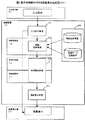
本装置の経路案内では、まず利用者にどの経路を案内するか決定させ、その後で経路に沿って案内を行う。本装置の特徴は案内経路決定手順にある。本装置の案内経路決定手順の動作制御部の動作フローの一実施例を図2に示す。この図は、利用者に目的地を入力させ、その目的地への経路の候補を複数挙げ、利用者に選択させるまでの処理フローである。 In the route guidance of this apparatus, the user first determines which route to guide, and then guides along the route. The feature of this apparatus is the guide route determination procedure. FIG. 2 shows an example of the operation flow of the operation control unit in the guide route determination procedure of this apparatus. This figure is a processing flow until the user inputs a destination, lists a plurality of route candidates to the destination, and allows the user to select.
利用者が入力部から行った入力を受け付け、対話的に目的地を決定する (211)。例えば、利用者が目的地の住所を入力すると地図表示部にその付近の地図が表示される。入力部を用いて地図上のどの地点を目的地とするか選択すると、その地点を目的地として選択したことになる。 The user receives input from the input unit and interactively determines the destination (211). For example, when the user inputs the address of the destination, a map in the vicinity is displayed on the map display unit. When a point on the map is selected as the destination using the input unit, the point is selected as the destination.
次に入力処理によって取得した目的地への経路を探索する (212)。経路探索処理では、まず現在位置取得部(113)により現在地を取得し、その現在地から目的地への経路を探索して最適経路を得る。探索は、一般的に用いられている公知の経路探索法で行うことができる。この際、距離優先、高速道路を使わない、時間優先など、複数の条件を考慮した探索を行うことでそれぞれ特徴のある複数の経路候補を提示することもできる。 Next, the route to the destination acquired by the input process is searched (212). In the route search process, the current location is first acquired by the current position acquisition unit (113), and the route from the current location to the destination is searched to obtain the optimum route. The search can be performed by a known route search method that is generally used. At this time, it is possible to present a plurality of characteristic route candidates by performing a search in consideration of a plurality of conditions such as distance priority, not using an expressway, and time priority.
従来技術では、経路探索処理によって得られた複数の経路をそのまま利用者へ提示し、どの経路で目的地へ向かうかを決定させる。しかし、本発明においては表示する経路の形状を要約することにより、その特徴を把握しやすくし利用者にどの経路を選択すべきかを判断しやすくする。その処理を地図要約処理(214)と呼ぶ。この詳細については後に説明する。
要約処理によって要約された地図は表示部に表示される (215)。座標値として得られた要約経路データを画面の解像度に合わせて縮小拡大し、座標系の調整などを行い画像表示部へ表示させる。その後は、利用者の指示に応じて処理が続行される。
In the prior art, a plurality of routes obtained by route search processing are presented to the user as they are, and a route to go to the destination is determined. However, in the present invention, by summarizing the shape of the route to be displayed, it is easy to grasp the characteristics and make it easier for the user to determine which route should be selected. This process is called a map summary process (214). Details of this will be described later.
The map summarized by the summary process is displayed on the display unit (215). The summary route data obtained as coordinate values is reduced or enlarged according to the resolution of the screen, and the coordinate system is adjusted and displayed on the image display unit. Thereafter, the processing is continued according to the user's instruction.
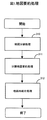
地図要約処理の手順の一実施例について図3を用いて説明する。最初に、地図の分割を行う(310)。この地図の分割では地図の冗長性を示す値(複雑度)を測定もしくは取得し、該冗長性指標を用いて領域分割を行う。冗長性の指標である複雑度を決定するには、後述するフラクタル次元を用いことができる。フラクタル次元は縮尺によらない定数となるので、地図によらず常に同じ基準で判断できるという利点がある。他にも、例えば線密度や点密度を用いれば、計算が容易になり高速に処理が行える。本実施例では冗長性として複雑度を用いたが、それ以外で冗長性を示す指標を用いることもできる。例えば、複数経路探索における始点終点付近は経路が込み合っていると推定されるので、始終点からの距離は冗長性として用いることができる。本実施例では地図データから冗長性(に相当する複雑度)を算出したが、地図データに含まれている情報で冗長性に相当する情報を用いることもできる。例えば、街路・山間等地域種別を予め地図に記録しておき、山間部は冗長であり、街路は冗長でないことを示す指標として用いることができる。これにより道路が込み入りがちな領域を要約し過ぎないようにできる。この分割処理については必ず領域ごとに行わなければならないというものではなく、例えばラウンドアバウト、高速道路などといった道路種別ごとに冗長性が異なる場合など、各線分ごとの冗長性に基づいて要約処理を行うようにすることも可能である。 An example of the map summarization process will be described with reference to FIG. First, the map is divided (310). In this map division, a value (complexity) indicating map redundancy is measured or acquired, and region division is performed using the redundancy index. The fractal dimension described later can be used to determine the complexity, which is an index of redundancy. Since the fractal dimension is a constant that does not depend on the scale, there is an advantage that it can always be determined based on the same standard regardless of the map. In addition, for example, if linear density or point density is used, calculation becomes easy and processing can be performed at high speed. In this embodiment, the complexity is used as the redundancy, but an index indicating the redundancy can be used in other cases. For example, since it is estimated that the route is crowded in the vicinity of the start point and end point in the multiple route search, the distance from the start point can be used as redundancy. In this embodiment, the redundancy (corresponding complexity) is calculated from the map data, but information corresponding to the redundancy can be used as information included in the map data. For example, area types such as streets / mountains can be recorded in advance on a map, and can be used as an index indicating that the mountains are redundant and the streets are not redundant. This avoids oversummarizing areas where roads tend to be crowded. This division processing does not necessarily have to be performed for each area. For example, when the redundancy differs for each road type such as roundabout and expressway, the summarization processing is performed based on the redundancy for each line segment. It is also possible to do so.
次に分割によって生成した地図それぞれについて、その冗長性に最も適した形で要約を行う(311)。どの要約が適しているかは、先の分割処理の際の基準となった指標を用いて判断する。ただし、この要約については分割された地図間での接続を維持するため端を移動させないものが望ましい。
最後に分割された地図を再度結合し、一枚の地図とする(312)。尚、仮想的に地図を分割したものとみなして各領域で個別に要約処理を行う場合には地図再結合処理は必要ない。
Next, each map generated by segmentation is summarized in a form most suitable for its redundancy (311). Which summary is suitable is determined using an index that is a reference in the previous division processing. However, it is desirable for this summary not to move the end in order to maintain the connection between the divided maps.
The last divided maps are combined again to form one map (312). Note that map recombination processing is not necessary when summarization processing is performed individually in each region on the assumption that the map is virtually divided.
以下では、各処理について説明する。
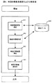
まず、地図分割処理(310)の一実施例について図4を用いて説明する。地図分割処理は地図を冗長性に応じた地図片(領域分割によって分割された後の地図データ)に分割する処理である。最初に、地図全体を包含する矩形を測定する(411)。これは、地物を全て含む外接矩形領域を決定すればよく、各地物の座標値の上限と下限から計算できる。次に地図片情報の作成を行う(412)まず、地図の表示領域全体を一定の閉図形領域ごとに分割した場合を想定する。これらの領域を区画と呼び、表示領域中の地図要素についてどの区画に含まれるかを判定、分類したものが地図片情報である。地図片情報作成の際、区画の境界上にかかる地図要素がある場合には、そこでその地図要素を分割するなどの処理が必要である。また、区画の形状は正方形、長方形、三角形など平面を埋め尽くすことが可能な任意の図形にすることができる。これにより、地図の図法や比率などに合わせて最適な分割方法を用いることができる。
Below, each process is demonstrated.
First, an example of the map division process (310) will be described with reference to FIG. The map division process is a process of dividing the map into map pieces (map data after being divided by area division) according to redundancy. First, a rectangle that encompasses the entire map is measured (411). This can be calculated from the upper and lower limits of the coordinate values of each feature by determining a circumscribed rectangular area that includes all the features. Next, map piece information is created (412) First, it is assumed that the entire map display area is divided into certain closed graphic areas. These areas are referred to as sections, and map pieces information is obtained by determining and classifying which section contains map elements in the display area. When the map piece information is created, if there is a map element on the boundary of the section, processing such as dividing the map element is necessary. Moreover, the shape of a division can be made into arbitrary figures which can fill up a plane, such as a square, a rectangle, and a triangle. As a result, it is possible to use an optimal dividing method in accordance with the map projection and ratio.
次に冗長性指標として用いるために、各地図片の複雑度を測定する (413)。本実施例においては各地図片のフラクタル次元を用いる。フラクタル次元の測定は、図5に示したようにボックス次元と呼ばれる次元を測定することで行う。ボックス次元とは以下のように定義される。「図形の外接矩形を小さな正方形に分割し、線分が入っている正方形の個数を数える。正方形の辺の長さを変えながら (510) 数を数え、辺の長さと正方形の数との関係を対数グラフ (511)にプロットしたとき、その傾き」をボックス次元と呼ぶ。この方法は領域統合の際に統合対象領域の正方形数を足しあげるだけで統合後の領域の次元を測定できる点が有利である。この測定法のかわりに、有限精度のデータからフラクタル次元を精度よく計算できる方法であれば、他の公知の測定法を用いてもよい。ただし本実施例で採用した方法では、線分の入っている正方形を計算する代わりに、線分を画像として描画することで代替できる。その場合、正方形を数えるには色を塗られた画素数を数えればよい。これにより、測定に際して装置の性能を十分発揮できる。 Next, the complexity of each map piece is measured for use as a redundancy index (413). In this embodiment, the fractal dimension of each map piece is used. The fractal dimension is measured by measuring a dimension called a box dimension as shown in FIG. Box dimensions are defined as follows: “Divide the circumscribed rectangle of the figure into small squares and count the number of squares containing the line segment. (510) Count the numbers while changing the length of the sides of the square, and the relationship between the length of the sides and the number of squares. Is plotted on the logarithmic graph (511), the slope is called the box dimension. This method is advantageous in that the dimension of the region after integration can be measured simply by adding the number of squares of the integration target regions at the time of region integration. Instead of this measurement method, any other known measurement method may be used as long as it can accurately calculate the fractal dimension from finite precision data. However, the method employed in this embodiment can be replaced by drawing a line segment as an image instead of calculating a square containing the line segment. In that case, to count the squares, it is only necessary to count the number of colored pixels. Thereby, the performance of the apparatus can be sufficiently exhibited during measurement.
最後に、図6に示した方式で各区画の併合(414)を行う。最初に各区画について隣接区画や区画内線分を記録した区画情報のリスト(611)を作成する。次に隣接区画の複雑度がその区画の複雑度に近いか判断し(612)、近ければ隣接区画を統合するという処理(613)を繰り返し各区画を統合し領域を作成する。この際、複雑度の近いものをすべて統合するのではなく、領域の個数が閾値以下になるまでの統合とすると、処理時間が抑えられるという効果がある。以上の処理により、複雑度ひいては冗長性がほぼ一定の領域への分割が行えることになる。なお、かならずしも地図を実際に区切らなければならないわけではなく、もし一様なパラメータでなくとも問題が生じないことが保障されていれば、道路やPOIなどの地物単位に要約度を決定できるパラメータを変えるだけでも同様の効果が期待できる。 Finally, merging of each section (414) is performed by the method shown in FIG. First, a list (611) of section information in which adjacent sections and extension lines are recorded for each section is created. Next, it is determined whether the complexity of the adjacent section is close to the complexity of the section (612), and if it is close, the process of integrating the adjacent sections (613) is repeated to integrate the sections and create a region. At this time, if all the objects having similar complexity are not integrated, but integration is performed until the number of regions is equal to or less than the threshold value, there is an effect that the processing time can be suppressed. By the above processing, the division into the areas where the complexity and the redundancy are almost constant can be performed. It is not always necessary to actually divide the map, and if it is guaranteed that no problem will occur even if it is not a uniform parameter, it is a parameter that can determine the degree of summarization for each feature unit such as road and POI The same effect can be expected just by changing.
冗長性ごとに区切られた領域それぞれについて、その冗長性から最適な要約度を推定し、要約処理を行う(311)。要約手段については要約度を変更できるものであれば、公知のものでよい。例えば、点間引きの閾値や変形可能な距離の上限、最適化の評価関数におけるパラメータ等を適宜変更する、手法を変える、要約後の地物の数を変更することなどが考えられる。尚、要約後の図形が領域の外へはみ出さないように回避処理を入れると、他の地図片に含まれる地図要素との間に生じる問題、例えば道路線分の交差などを自動的に回避できる。 For each area divided for each redundancy, an optimum summarization degree is estimated from the redundancy, and a summarization process is performed (311). Any summarizing means may be used as long as the summarization degree can be changed. For example, it is conceivable to appropriately change the threshold for point thinning, the upper limit of the deformable distance, the parameters in the optimization evaluation function, change the method, or change the number of features after summarization. In addition, when avoidance processing is performed so that the figure after summarization does not protrude outside the area, problems such as intersections between road lines are automatically avoided. it can.
分割地図要約処理(311)の一例として、ミニマックス法とその要約度調整について、図7を用いて説明する。ミニマックス法はリンク補間点の点間引きを行う方法である。この方法は、基本的には線分列の始点(710)と終点(711)を結んだ直線から線分中の各点への垂線距離(712)を計算し、その距離が最大になる点(713)を残すという方法である。その際、残された点を分割点として二つの線分列を作り再帰的にこの処理を加える(714)。この再帰処理の終了条件は、最大垂線距離が閾値εを下回るときとする。この閾値を要約度の指標とし、冗長性を示す複雑度によって閾値を変動させる。たとえば、フラクタル次元dに対してε=αdが適切な要約度となる定数αを試行によって決定して用いる。なお、ミニマックス法による点間引きでは両端の点は間引かれないため、領域の境界線上の点を端点とすれば領域接続時の問題は生じない。 As an example of the divided map summarization process (311), the minimax method and the summarization level adjustment will be described with reference to FIG. The minimax method is a method of thinning out the link interpolation points. This method basically calculates the perpendicular distance (712) from the straight line connecting the start point (710) and end point (711) of the line segment sequence to each point in the line segment, and the point where the distance becomes the maximum (713) is left. At this time, two line segments are created with the remaining points as the dividing points, and this process is recursively added (714). The recursion process is terminated when the maximum perpendicular distance is less than the threshold value ε. This threshold value is used as an index of the summarization level, and the threshold value is varied depending on the complexity indicating redundancy. For example, a constant α for which ε = αd is an appropriate summarization level for the fractal dimension d is determined by trial and used. It should be noted that since points at both ends are not thinned out by point thinning by the minimax method, problems at the time of region connection do not occur if the points on the boundary line of the region are used as end points.
要約方法を調整する例としては、直線化・スプライン曲線近似があげられる。この方式では複雑度が閾値以上であれば直線として表示し、閾値以下であればスプライン曲線近似で表示する。直線とする部分では、点間引きを行った後で、たとえば各線分の中点を中心に水平垂直・45度の最も近い角度に回転させる図形生成処理を行うこともできる(715)。このとき、地図片境界にあたる点に関しては端点を中心に回転させることで地図の結合を滑らかにできる。他にもグリッド上に点や線をのせる方法など要約度の変えられる要約処理には多数あり、それらを用いてもよい。また、それらとは別に要約度を変えられない処理を構成に含むことも可能である。これらの要約方式については要約度を決定できるという以外に制限がないため、目的によって任意の形状変形が行える。 Examples of adjusting the summarization method include linearization and spline curve approximation. In this method, if the complexity is equal to or higher than the threshold value, it is displayed as a straight line. In the portion to be a straight line, it is also possible to perform graphic generation processing for rotating to the closest angle of 45 degrees in the horizontal and vertical directions around the midpoint of each line segment after the point thinning (715). At this time, the map can be smoothly joined by rotating the point corresponding to the map piece boundary around the end point. There are many other summarization processes that can change the degree of summarization, such as a method of placing points or lines on the grid, and these may be used. In addition to the above, it is possible to include processing whose summarization level cannot be changed in the configuration. Since these summarization methods are not limited except that the summarization degree can be determined, arbitrary shape deformation can be performed depending on the purpose.
以上の処理を行った後に(312)に示された結合を行うことで要約後の地図を一枚の地図として出力できる。この結合処理は、基本的には地図片毎に変形を行った後で、そのデータを結合して一つの地図を作成するか、あるいは結果を分割前の地図に反映させる処理となる。ただし、図8に示すように結合の境界(810)で不整合を生じない手法を行うことで、より自然に地図の結合ができる。例えば、本実施例における直線化・スプライン曲線近似の変形においては、地図境界上にある線分の角度を記録しておき、スプライン近似の角度や直線の方向をあわせる(811)ようにできる。本実施例以外の例では、接続をスムーズにするための補間点を追加する(812)などにより、分割された地図の継ぎ目を自然にみせることもできる。 After performing the above processing, the combined map shown in (312) can be used to output the map after summarization as a single map. This combining process is basically a process of deforming each map piece and then combining the data to create one map or reflecting the result on the map before division. However, as shown in FIG. 8, the map can be combined more naturally by performing a technique that does not cause inconsistency at the boundary (810) of the connection. For example, in the modification of the linearization / spline curve approximation in this embodiment, the angle of the line segment on the map boundary is recorded, and the angle of the spline approximation and the direction of the straight line can be matched (811). In examples other than the present embodiment, it is possible to make the joints of the divided maps appear naturally by adding an interpolation point for smooth connection (812).
本願適応の利点を示すため、図9に例を示す。この図は探索して得られた経路を表示し、案内する経路を選択(910)させる画面である。この画面向けに経路の形状を要約した地図を作成する。この経路の要約を一様な要約度によって要約すると、図10および図11のようになる。図10は細部の情報を残すために要約度を小さくし、点間引きをあまり行わなかった場合の想定図である。この場合、全体的に不要な情報(1010)が残されているため、形状があまり単純化されない。また図11は逆に十分点間引きを行った場合の想定図であるが、この図では細かい部分の情報が失われてしまい、必要な情報(1110)が残らない。経路探索においては街路や山道、高速道路など、多種多様な形状が同時に存在するため、容易に要約できない。 An example is shown in FIG. 9 in order to show the advantages of adaptation of the present application. This figure is a screen for displaying a route obtained by searching and selecting (910) a route to be guided. Create a map that summarizes the shape of the route for this screen. The summary of this route is summarized as shown in FIGS. 10 and 11 by uniform summarization. FIG. 10 is an assumption diagram in the case where the summarization level is reduced in order to leave detailed information and the dot thinning is not performed so much. In this case, since unnecessary information (1010) remains as a whole, the shape is not greatly simplified. In contrast, FIG. 11 is an assumption diagram in the case where sufficient point thinning has been performed, but in this figure, detailed information is lost and necessary information (1110) does not remain. In route search, various shapes such as streets, mountain roads, and highways exist at the same time, so it cannot be easily summarized.
そこで本発明の実施結果の例を図12に示す。複雑な領域(1210)(1211)と単純な領域(1212)で要約度を切り替えているためそれぞれの形状に適した要約度で間引きが行われており、あとは要約度の大きな領域では曲線化表示し、他は回転処理(715)を加えるなどの対応をおこなえばよい。これにより、様々な道路などを含む経路の全体図を要約表示することが可能となる。本装置では形状による判断を行っているが、街路や高速道路など、形状に限らず要約処理に必要な特徴を抽出できれば同様の効果が得られる。この処理の最終的な画面表示例を図13に示す。この画面では要約度の低い領域では経路をスプライン曲線で表示し、そうでない領域では方向を揃えるという処理を行っている。図9と図13を比較して見ることで、要約表示によって経路情報がわかりやすく伝わるようになったことがわかる。また、図13は図12と比べても、細かな形状が残りにくい曲線化処理を複雑度が小さい領域に適用することで、経路の違いを把握するのに必要な情報だけが強調されている。これら図12と図13、図9の表示をユーザの入力や初期設置で切り替えられるようにしても良い。 An example of the results of implementation of the present invention is shown in FIG. Since the summarization level is switched between the complex area (1210) (1211) and the simple area (1212), thinning is performed at the summarization level suitable for each shape, and then the area with high summarization level is curved. It is only necessary to perform a response such as adding a rotation process (715). This makes it possible to display a summary of the entire route including various roads. Although this device makes a judgment based on the shape, the same effect can be obtained if features necessary for the summary processing can be extracted, not limited to the shape, such as streets and highways. FIG. 13 shows a final screen display example of this process. On this screen, the route is displayed as a spline curve in the low summarization area, and the direction is aligned in the other areas. By comparing FIG. 9 and FIG. 13, it can be seen that the route information can be easily understood by the summary display. Compared to FIG. 12, FIG. 13 emphasizes only the information necessary to understand the path difference by applying the curving process, which is difficult to retain fine shapes, to areas with low complexity. . 12, 13, and 9 may be switched by user input or initial installation.
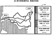
本発明はカーナビにおける経路探索の他にも様々な場面で適用できる。例えば経路案内の最中に迂回路を選択するような状況である。その例を図14に示す。この図は案内経路中に渋滞が発生した際、迂回路の要約図(1410)を普通の地図表示との2画面表示した例である。この地図は一様要約度で要約を行っている。図15に示した原図から一様に細道路を省略し、残りを直線化垂直水平化したものである。この図により案内経路と迂回路の位置関係は短時間で把握できる。しかし迂回路へ分岐する地点や合流する地点の情報がなく、どこで経路から外れるのかという情報が得られない。 図16に示したように要約度を小さくした図を用いると、表示される情報量は増加するが、地図複雑であり、冗長であるために短時間で情報把握するのは困難である。 The present invention can be applied to various scenes other than route search in car navigation systems. For example, the situation is such that a detour is selected during route guidance. An example is shown in FIG. This figure is an example in which a detour summary diagram (1410) is displayed in two screens with a normal map display when a traffic jam occurs in the guidance route. This map summarizes with uniform summarization. The narrow road is uniformly omitted from the original drawing shown in FIG. 15, and the rest is linearized, vertical and horizontal. From this figure, the positional relationship between the guide route and the detour can be grasped in a short time. However, there is no information on the point of branching to the detour and the point of joining, and information on where the route departs cannot be obtained. If a diagram with a reduced summarization level as shown in FIG. 16 is used, the amount of information displayed increases, but it is difficult to grasp information in a short time because the map is complex and redundant.
そこで、現在地付近と合流点付近であることを冗長性指標とし、本発明を適用したのが図17である。出発地、目的地付近であるという特性をもった領域 (1710)(1711)でのみ要約度を小さくし、多くの地物を表示する。他にも詳細な地名や小さな河川を表示するなど、詳細な情報を伝えることもできる。この結果、案内経路と迂回路の位置関係が把握でき、かつ詳細情報も得られる地図(図18)が生成できるようになった。図14と図18を比較することで、その効果がわかる。
以上の実施形態により、以下のような利点が得られる。
Thus, FIG. 17 shows the application of the present invention with the redundancy index being near the current location and near the junction. The summarization level is reduced only in the areas (1710) and (1711) with the characteristics of being near the start and destination, and many features are displayed. Other detailed information such as displaying detailed place names and small rivers can also be transmitted. As a result, a map (FIG. 18) can be generated in which the positional relationship between the guide route and the detour can be grasped and detailed information can be obtained. Comparing FIG. 14 and FIG. 18 shows the effect.
According to the above embodiment, the following advantages can be obtained.
(1)領域の冗長性を考慮した要約を領域毎に行うため、冗長でない領域で必要な情報を残すことができる。よって、例えば経路を選択するための情報が提供でき望ましい経路案内を受けることが出来る。 (1) Since the summarization considering the redundancy of the area is performed for each area, necessary information can be left in the non-redundant area. Therefore, for example, information for selecting a route can be provided and a desired route guidance can be received.
(2)差異を特に強調する必要のない冗長な領域の情報を省略できるため、注目すべき情報がどこにあるか、短時間で判別できる。 (2) Since redundant area information that does not require particular emphasis on the difference can be omitted, it is possible to determine in a short time where there is noticeable information.
(3)経路全体を表示する際、要約する情報を冗長な部分に制限できるため、従来手法で行うよりも問題なく要約できる形状が多くなり、不具合が起きる可能性が減少する。 (3) Since the information to be summarized can be limited to redundant portions when displaying the entire route, the number of shapes that can be summarized without any problems is increased as compared with the conventional method, and the possibility of malfunctions is reduced.
上記本願はカーナビにおける実施例を説明したが、本願は地図情報を表示するどの装置にも適応することができる。また、道路だけではなく、海岸線などの背景データや建物の形状など、地図を構成する任意の地物についても同様である。特に海岸線はフラクタル図形なので、冗長性としてフラクタル次元から計算される複雑度を用いれば海岸線の種類ごとに要約度を設定でき、非常に有効である。
又、本願の処理はコンピュータがプログラムを読み込むことで実現される。又、ソフトウェアとハードウェアの協調処理によって行われるものであっても良い。
Although the above application has described an embodiment in a car navigation system, the present application can be applied to any device that displays map information. The same applies not only to roads, but also to any feature that constitutes a map, such as background data such as coastlines and the shape of buildings. In particular, since the coastline is a fractal figure, if the complexity calculated from the fractal dimension is used as redundancy, the summarization level can be set for each type of coastline, which is very effective.
The processing of the present application is realized by a computer reading a program. Further, it may be performed by cooperative processing of software and hardware.
111 動作制御部
117 地図要約部
118 地図分割部
214 地図要約処理
310 地図分割処理
311 分割地図要約処理
312 地図再結合処理
1210 始点付近の複雑度が高い領域
1211 終点付近の複雑度が高い領域
1212 低複雑度領域。
111 Operation control unit
117 Map summary section
118 Map division
214 Map summary processing
310 Map segmentation
311 Split map summary processing
312 Map recombination processing
1210 High complexity area near the start point
1211 High complexity area near the end point
1212 Low complexity area.
Claims (7)
上記制御部は
上記記録部から表示対象の地図データを読み出して複数の領域に分割し、
冗長性指標として上記領域中の地図要素の複雑度をフラクタル次元を用いて計測し、
上記複数の領域毎の冗長性指標を決定し、
上記冗長性指標に応じて決定される要約方法で上記各複数の領域を要約し、
上記要約された複数の領域の地図データを再結合し、
表示手段に表示させることを特徴とする地図処理装置。 A recording unit for recording map data and a control unit;
The control unit reads map data to be displayed from the recording unit and divides it into a plurality of areas,
As a redundancy index, measure the complexity of the map elements in the region using the fractal dimension,
Determine a redundancy index for each of the plurality of regions,
Summarizing each of the plurality of regions with a summarization method determined according to the redundancy index,
Recombining the map data of multiple areas summarized above,
A map processing apparatus, characterized by being displayed on a display means.
現在の位置を取得する位置取得部と、 A position acquisition unit for acquiring the current position;
ユーザの指示入力を受け付ける入力部と、 An input unit for receiving user instruction input;
上記地図データを処理する制御部と、 A control unit for processing the map data;
上記処理された地図データを表示する表示部を有し、 A display unit for displaying the processed map data;
上記制御部は、 The control unit
上記位置取得部によって取得された現在位置と入力部を介して取得した目的地との間の経路を探索し、 Search for a route between the current position acquired by the position acquisition unit and the destination acquired via the input unit,
上記経路を含む地図データを上記記録部から読み出して複数の領域に分割し、 The map data including the route is read from the recording unit and divided into a plurality of areas,
冗長性指標として上記領域中の地図要素の複雑度をフラクタル次元を用いて計測し、As a redundancy index, measure the complexity of the map elements in the region using the fractal dimension,
上記複数の領域毎の冗長性指標を決定し、 Determine a redundancy index for each of the plurality of regions,
上記冗長性指標に応じて決定される要約方法で上記各複数の領域を要約し、 Summarizing each of the plurality of regions with a summarization method determined according to the redundancy index,
上記要約された複数の領域の地図データを再結合し、 Recombining the map data of multiple areas summarized above,
上記結合された地図データを上記表示部に表示して経路案内することを特徴とするナビゲーション装置。 A navigation apparatus characterized in that the combined map data is displayed on the display unit for route guidance.
Priority Applications (4)
| Application Number | Priority Date | Filing Date | Title |
|---|---|---|---|
| JP2005038563A JP4613075B2 (en) | 2005-02-16 | 2005-02-16 | Map processing device, navigation device, and map display method |
| US11/354,051 US20060184317A1 (en) | 2005-02-16 | 2006-02-15 | Map processor, navigation device and map displaying method |
| DE602006010454T DE602006010454D1 (en) | 2005-02-16 | 2006-02-16 | Card processor, navigation device and map display device |
| EP06003108A EP1693800B1 (en) | 2005-02-16 | 2006-02-16 | Map processor, navigation device and map displaying method |
Applications Claiming Priority (1)
| Application Number | Priority Date | Filing Date | Title |
|---|---|---|---|
| JP2005038563A JP4613075B2 (en) | 2005-02-16 | 2005-02-16 | Map processing device, navigation device, and map display method |
Publications (3)
| Publication Number | Publication Date |
|---|---|
| JP2006227767A JP2006227767A (en) | 2006-08-31 |
| JP2006227767A5 JP2006227767A5 (en) | 2008-04-03 |
| JP4613075B2 true JP4613075B2 (en) | 2011-01-12 |
Family
ID=36481421
Family Applications (1)
| Application Number | Title | Priority Date | Filing Date |
|---|---|---|---|
| JP2005038563A Expired - Fee Related JP4613075B2 (en) | 2005-02-16 | 2005-02-16 | Map processing device, navigation device, and map display method |
Country Status (4)
| Country | Link |
|---|---|
| US (1) | US20060184317A1 (en) |
| EP (1) | EP1693800B1 (en) |
| JP (1) | JP4613075B2 (en) |
| DE (1) | DE602006010454D1 (en) |
Families Citing this family (23)
| Publication number | Priority date | Publication date | Assignee | Title |
|---|---|---|---|---|
| KR100697098B1 (en) * | 2004-06-30 | 2007-03-20 | 에스케이 주식회사 | System and method for providing telematics service using guidance point map |
| DE102005039283A1 (en) * | 2005-08-19 | 2007-02-22 | Robert Bosch Gmbh | Method for operating a navigation system and navigation system |
| JP5086562B2 (en) | 2006-04-17 | 2012-11-28 | クラリオン株式会社 | Navigation device |
| JP4961605B2 (en) * | 2006-08-29 | 2012-06-27 | アイシン・エィ・ダブリュ株式会社 | Data management system and data update method |
| JP2008076593A (en) * | 2006-09-20 | 2008-04-03 | Hirotsu Sokichi | Simplified map generating apparatus and simplified map generation method |
| JP5121255B2 (en) * | 2007-02-28 | 2013-01-16 | クラリオン株式会社 | Navigation device |
| US10605610B2 (en) * | 2007-04-09 | 2020-03-31 | Ian Cummings | Apparatus and methods for reducing data transmission in wireless client-server navigation systems |
| JP4929057B2 (en) * | 2007-05-30 | 2012-05-09 | アジア航測株式会社 | Diagram compression processing program |
| JP5478008B2 (en) * | 2007-10-29 | 2014-04-23 | 三菱電機株式会社 | Deformation map generator |
| CN101532842A (en) * | 2008-03-13 | 2009-09-16 | 联发科技(合肥)有限公司 | Path planning method for determining target route from starting point to ending point and device thereof |
| WO2009150748A1 (en) * | 2008-06-13 | 2009-12-17 | パイオニア株式会社 | Map data recording device, map display, map data recording method, map display method, map data recording program, map display program, and recording medium |
| US8938446B2 (en) * | 2009-01-26 | 2015-01-20 | Google Inc. | System and method of transmitting search results based on arbitrary queries |
| US8037166B2 (en) | 2009-01-26 | 2011-10-11 | Google Inc. | System and method of displaying search results based on density |
| AU2012261938B2 (en) | 2011-06-03 | 2015-03-19 | Apple Inc. | Devices and methods for comparing and selecting alternative navigation routes |
| EP2551639A1 (en) * | 2011-07-27 | 2013-01-30 | NNG Szoftverfejlesztö Kft. | Routing method for road navigation devices with ranking of route alternatives and road navigation device |
| JP5731425B2 (en) * | 2012-02-27 | 2015-06-10 | 株式会社トヨタマップマスター | Processing unit designating apparatus and method, computer program for designating processing unit, and recording medium storing computer program |
| JP6060646B2 (en) * | 2012-11-27 | 2017-01-18 | 株式会社デンソー | Map display device and map display system |
| US9304007B2 (en) | 2013-08-13 | 2016-04-05 | Mapquest, Inc. | Systems and methods for providing mapping services including route break point recommendations |
| DE112016003285B4 (en) * | 2015-07-22 | 2022-12-22 | Honda Motor Co., Ltd. | Route generator, route generation method and route generation program |
| CN107976688A (en) * | 2016-10-25 | 2018-05-01 | 菜鸟智能物流控股有限公司 | Obstacle detection method and related device |
| CN107609080B (en) * | 2017-09-05 | 2024-02-02 | 上海博泰悦臻网络技术服务有限公司 | Map data acquisition method and system, electronic equipment and storage medium |
| JP6976659B2 (en) * | 2018-01-09 | 2021-12-08 | アルパイン株式会社 | Map display device and map display method |
| JP6633125B2 (en) * | 2018-04-26 | 2020-01-22 | 株式会社Vip | In-vehicle device, determination system, program, and determination method |
Citations (3)
| Publication number | Priority date | Publication date | Assignee | Title |
|---|---|---|---|---|
| JPH10177338A (en) * | 1996-10-15 | 1998-06-30 | Matsushita Electric Ind Co Ltd | Traffic information display device |
| JPH11237833A (en) * | 1998-02-23 | 1999-08-31 | Nippon Telegr & Teleph Corp <Ntt> | Method and device for deforming map and storage medium recording map deforming program |
| JP2002206933A (en) * | 2000-11-29 | 2002-07-26 | Alpine Electronics Inc | Method of displaying poi icon for navigation system |
Family Cites Families (9)
| Publication number | Priority date | Publication date | Assignee | Title |
|---|---|---|---|---|
| US7197500B1 (en) * | 1996-10-25 | 2007-03-27 | Navteq North America, Llc | System and method for use and storage of geographic data on physical media |
| US5968109A (en) * | 1996-10-25 | 1999-10-19 | Navigation Technologies Corporation | System and method for use and storage of geographic data on physical media |
| US6424933B1 (en) * | 2000-03-17 | 2002-07-23 | Vicinity Corporation | System and method for non-uniform scaled mapping |
| JP2002098538A (en) * | 2000-09-27 | 2002-04-05 | Alpine Electronics Inc | Navigation system and method for displaying information of pseudo three dimensional map |
| US7254249B2 (en) * | 2001-03-05 | 2007-08-07 | Digimarc Corporation | Embedding location data in video |
| US7440875B2 (en) * | 2002-01-23 | 2008-10-21 | M-Spatial Lmited | Schematic generation |
| JP4004818B2 (en) * | 2002-02-28 | 2007-11-07 | 松下電器産業株式会社 | Position information transmission apparatus and method |
| US7076365B2 (en) * | 2003-05-12 | 2006-07-11 | Circumnav Networks, Inc. | Enhanced dead reckoning method |
| JP4138574B2 (en) * | 2003-05-21 | 2008-08-27 | 株式会社日立製作所 | Car navigation system |
-
2005
- 2005-02-16 JP JP2005038563A patent/JP4613075B2/en not_active Expired - Fee Related
-
2006
- 2006-02-15 US US11/354,051 patent/US20060184317A1/en not_active Abandoned
- 2006-02-16 EP EP06003108A patent/EP1693800B1/en not_active Expired - Fee Related
- 2006-02-16 DE DE602006010454T patent/DE602006010454D1/en active Active
Patent Citations (3)
| Publication number | Priority date | Publication date | Assignee | Title |
|---|---|---|---|---|
| JPH10177338A (en) * | 1996-10-15 | 1998-06-30 | Matsushita Electric Ind Co Ltd | Traffic information display device |
| JPH11237833A (en) * | 1998-02-23 | 1999-08-31 | Nippon Telegr & Teleph Corp <Ntt> | Method and device for deforming map and storage medium recording map deforming program |
| JP2002206933A (en) * | 2000-11-29 | 2002-07-26 | Alpine Electronics Inc | Method of displaying poi icon for navigation system |
Also Published As
| Publication number | Publication date |
|---|---|
| JP2006227767A (en) | 2006-08-31 |
| US20060184317A1 (en) | 2006-08-17 |
| EP1693800A1 (en) | 2006-08-23 |
| DE602006010454D1 (en) | 2009-12-31 |
| EP1693800B1 (en) | 2009-11-18 |
Similar Documents
| Publication | Publication Date | Title |
|---|---|---|
| JP4613075B2 (en) | Map processing device, navigation device, and map display method | |
| EP3673407B1 (en) | Automatic occlusion detection in road network data | |
| US20230245413A1 (en) | Intelligently placing labels | |
| US10302438B2 (en) | Probe based identification and validation of roundabout junctions | |
| US7920966B2 (en) | Navigation apparatuses, methods, and programs | |
| EP1873494B1 (en) | Navigation apparatus | |
| US8977487B2 (en) | Navigation device and guide route search method | |
| US9778061B2 (en) | Road density calculation | |
| JP3173983B2 (en) | Route selection method and system | |
| US8515664B2 (en) | Digital map signpost system | |
| US8204680B1 (en) | Method of operating a navigation system to provide road curvature | |
| JPWO2005020186A1 (en) | Map display method | |
| EP2689213B1 (en) | Management of icons for digital maps | |
| US9500494B2 (en) | Providing maneuver indicators on a map | |
| US8370059B2 (en) | Navigation apparatus and navigation program | |
| EP2009400A2 (en) | Vehicle position recognition device, navigation device, vehicle position recognition method | |
| US20110141115A1 (en) | Interactive method for displaying integrated schematic network plans and geographic maps | |
| EP2503290A1 (en) | Curved labeling in digital maps | |
| JP2008014973A (en) | Navigation device | |
| US20150185026A1 (en) | Generating a sequence of lane-specific driving directions | |
| JP6789334B2 (en) | Electronic map display method and equipment | |
| CN111238498A (en) | Lane-level display road map generation method and device and related system | |
| JP2964832B2 (en) | Road map display device | |
| JP2006527838A (en) | Method and system for providing map data using a mobile communication terminal | |
| KR101062664B1 (en) | Period display method of linear map data and its device |
Legal Events
| Date | Code | Title | Description |
|---|---|---|---|
| A521 | Written amendment |
Free format text: JAPANESE INTERMEDIATE CODE: A523 Effective date: 20080201 |
|
| A621 | Written request for application examination |
Free format text: JAPANESE INTERMEDIATE CODE: A621 Effective date: 20080201 |
|
| A521 | Written amendment |
Free format text: JAPANESE INTERMEDIATE CODE: A523 Effective date: 20080204 |
|
| A711 | Notification of change in applicant |
Free format text: JAPANESE INTERMEDIATE CODE: A712 Effective date: 20100212 |
|
| A977 | Report on retrieval |
Free format text: JAPANESE INTERMEDIATE CODE: A971007 Effective date: 20100622 |
|
| A131 | Notification of reasons for refusal |
Free format text: JAPANESE INTERMEDIATE CODE: A131 Effective date: 20100629 |
|
| A521 | Written amendment |
Free format text: JAPANESE INTERMEDIATE CODE: A523 Effective date: 20100806 |
|
| TRDD | Decision of grant or rejection written | ||
| A01 | Written decision to grant a patent or to grant a registration (utility model) |
Free format text: JAPANESE INTERMEDIATE CODE: A01 Effective date: 20101012 |
|
| A01 | Written decision to grant a patent or to grant a registration (utility model) |
Free format text: JAPANESE INTERMEDIATE CODE: A01 |
|
| A61 | First payment of annual fees (during grant procedure) |
Free format text: JAPANESE INTERMEDIATE CODE: A61 Effective date: 20101018 |
|
| FPAY | Renewal fee payment (event date is renewal date of database) |
Free format text: PAYMENT UNTIL: 20131022 Year of fee payment: 3 |
|
| R150 | Certificate of patent or registration of utility model |
Free format text: JAPANESE INTERMEDIATE CODE: R150 |
|
| R250 | Receipt of annual fees |
Free format text: JAPANESE INTERMEDIATE CODE: R250 |
|
| R250 | Receipt of annual fees |
Free format text: JAPANESE INTERMEDIATE CODE: R250 |
|
| R250 | Receipt of annual fees |
Free format text: JAPANESE INTERMEDIATE CODE: R250 |
|
| LAPS | Cancellation because of no payment of annual fees |