JP4612090B2 - Scheduling data transmission to improve power efficiency in wireless networks - Google Patents
Scheduling data transmission to improve power efficiency in wireless networks Download PDFInfo
- Publication number
- JP4612090B2 JP4612090B2 JP2008516439A JP2008516439A JP4612090B2 JP 4612090 B2 JP4612090 B2 JP 4612090B2 JP 2008516439 A JP2008516439 A JP 2008516439A JP 2008516439 A JP2008516439 A JP 2008516439A JP 4612090 B2 JP4612090 B2 JP 4612090B2
- Authority
- JP
- Japan
- Prior art keywords
- scheduled
- nodes
- communication
- uplink
- section
- Prior art date
- Legal status (The legal status is an assumption and is not a legal conclusion. Google has not performed a legal analysis and makes no representation as to the accuracy of the status listed.)
- Active
Links
Images


Classifications
-
- H—ELECTRICITY
- H04—ELECTRIC COMMUNICATION TECHNIQUE
- H04W—WIRELESS COMMUNICATION NETWORKS
- H04W72/00—Local resource management
- H04W72/12—Wireless traffic scheduling
-
- H—ELECTRICITY
- H04—ELECTRIC COMMUNICATION TECHNIQUE
- H04W—WIRELESS COMMUNICATION NETWORKS
- H04W72/00—Local resource management
- H04W72/50—Allocation or scheduling criteria for wireless resources
- H04W72/535—Allocation or scheduling criteria for wireless resources based on resource usage policies
-
- H—ELECTRICITY
- H04—ELECTRIC COMMUNICATION TECHNIQUE
- H04W—WIRELESS COMMUNICATION NETWORKS
- H04W52/00—Power management, e.g. TPC [Transmission Power Control], power saving or power classes
- H04W52/02—Power saving arrangements
-
- H—ELECTRICITY
- H04—ELECTRIC COMMUNICATION TECHNIQUE
- H04W—WIRELESS COMMUNICATION NETWORKS
- H04W84/00—Network topologies
- H04W84/02—Hierarchically pre-organised networks, e.g. paging networks, cellular networks, WLAN [Wireless Local Area Network] or WLL [Wireless Local Loop]
- H04W84/10—Small scale networks; Flat hierarchical networks
- H04W84/12—WLAN [Wireless Local Area Networks]
-
- H—ELECTRICITY
- H04—ELECTRIC COMMUNICATION TECHNIQUE
- H04W—WIRELESS COMMUNICATION NETWORKS
- H04W52/00—Power management, e.g. TPC [Transmission Power Control], power saving or power classes
- H04W52/02—Power saving arrangements
- H04W52/0209—Power saving arrangements in terminal devices
- H04W52/0212—Power saving arrangements in terminal devices managed by the network, e.g. network or access point is master and terminal is slave
- H04W52/0216—Power saving arrangements in terminal devices managed by the network, e.g. network or access point is master and terminal is slave using a pre-established activity schedule, e.g. traffic indication frame
-
- Y—GENERAL TAGGING OF NEW TECHNOLOGICAL DEVELOPMENTS; GENERAL TAGGING OF CROSS-SECTIONAL TECHNOLOGIES SPANNING OVER SEVERAL SECTIONS OF THE IPC; TECHNICAL SUBJECTS COVERED BY FORMER USPC CROSS-REFERENCE ART COLLECTIONS [XRACs] AND DIGESTS
- Y02—TECHNOLOGIES OR APPLICATIONS FOR MITIGATION OR ADAPTATION AGAINST CLIMATE CHANGE
- Y02D—CLIMATE CHANGE MITIGATION TECHNOLOGIES IN INFORMATION AND COMMUNICATION TECHNOLOGIES [ICT], I.E. INFORMATION AND COMMUNICATION TECHNOLOGIES AIMING AT THE REDUCTION OF THEIR OWN ENERGY USE
- Y02D30/00—Reducing energy consumption in communication networks
- Y02D30/70—Reducing energy consumption in communication networks in wireless communication networks
Abstract
Description
本出願は、米国仮出願第60/691,220号(2005年6月16日出願)、名称"Scheduling and Sequencing of Data/STAs and Information for Maximal Power Efficiency in Aggregated Frames"に対する優先権を主張するものであり、参照することにより本書に組み込まれる。 This application claims priority to US Provisional Application No. 60 / 691,220 (filed June 16, 2005), entitled “Scheduling and Sequencing of Data / STAs and Information for Maximal Power Efficiency in Aggregated Frames”. , Incorporated herein by reference.
本出願は、米国仮出願第60/620,246号(2004年10月19日出願)、名称"Scheduling and Sequencing of Data and Information for Maximal Power Efficiency in Aggregated Frames"に関連するものであり、参照することにより本書に組み込まれる。 This application is related to US Provisional Application No. 60 / 620,246 (filed Oct. 19, 2004), entitled "Scheduling and Sequencing of Data and Information for Maximal Power Efficiency in Aggregated Frames", by reference. Built into this book.
無線ローカルエリアネットワーク(WLAN)アクセスの急速な普及、およびWLANの受信可能範囲に対する要求の増加により、極めて多数のアクセスポイント(AP)の設置が推進されている。最も一般的なWLAN技術は、IEEE(Institute of Electrical and Electronics Engineers: 電気電子技術者協会) 802.11b、IEEE 802.11g、およびIEEE 802.11aの仕様のような、業界仕様のIEEE 802.11ファミリに記載されたものである。既存の802.11技術の改善に関連する仕様の開発には、複数の異なる802.11のタスクグループが関わっている。 Due to the rapid spread of wireless local area network (WLAN) access and the increasing demand for WLAN coverage, the installation of a very large number of access points (APs) is being promoted. The most common WLAN technologies have been described in industry-specific IEEE 802.11 families, such as IEEE (Institute of Electrical and Electronics Engineers) 802.11b, IEEE 802.11g, and IEEE 802.11a specifications Is. The development of specifications related to improvements in existing 802.11 technology involves several different 802.11 task groups.
消費電力およびバッテリ寿命は、無線デバイスの課題である。消費電力の低減およびバッテリ寿命の向上に対して、複数の節電手法が提案されている。しかし、現在の手法は、消費電力の問題に十分対処していないだけでなく、無線デバイスの低電力状態に対するオン/オフ動作の移行回数を十分に低減していない。 Power consumption and battery life are challenges for wireless devices. Several power saving methods have been proposed for reducing power consumption and improving battery life. However, current approaches do not fully address the problem of power consumption, but also do not sufficiently reduce the number of on / off operation transitions for low power states of wireless devices.
無線ネットワーク内の節電供給のためのデータ伝送のスケジューリングに関して、種々の実施形態を開示する。 Various embodiments are disclosed for scheduling data transmission for power saving provision in a wireless network.
ある例示的な実施形態においては、方法が提供される。前記方法は、フレームシーケンス中における、無線ネットワークの1つ以上のノードのための複数のアップリンクおよび/またはダウンリンク伝送期間を特定するスケジュールを含むフレームを伝送することを含む。前記フレームシーケンス内において、前記アップリンク伝送は、前記ダウンリンク伝送の後にスケジュールすることが可能であり、スケジュールされたダウンリンク伝送だけを前記フレームシーケンス中に有する1つ以上のノードは、前記ダウンリンク伝送の開始時またはほぼ開始時にダウンリンク伝送を行うようにスケジュールされている。ある例示的な実施形態では、前記伝送されるフレームは、例えばパワーセーブマルチポール(Power Save Multi Poll: PSMP)メッセージとすることが可能であり、前記フレームシーケンスは、例えばPSMPシーケンスとすることが可能である。さらに別の例示的な実施形態では、前記伝送されるフレームは、例えばIEEE 802.11nパワーセーブマルチポール(PSMP)メッセージとすることが可能である。 In certain exemplary embodiments, a method is provided. The method includes transmitting a frame that includes a schedule that identifies a plurality of uplink and / or downlink transmission periods for one or more nodes of a wireless network in a frame sequence. Within the frame sequence, the uplink transmission may be scheduled after the downlink transmission, and one or more nodes having only scheduled downlink transmissions in the frame sequence may be the downlink transmission. Scheduled to perform downlink transmission at or near the beginning of transmission. In an exemplary embodiment, the transmitted frame can be, for example, a Power Save Multi Poll (PSMP) message, and the frame sequence can be, for example, a PSMP sequence. It is. In yet another exemplary embodiment, the transmitted frame may be, for example, an IEEE 802.11n power save multipole (PSMP) message.
別の例示的な実施形態では、方法が提供される。前記方法は、ネットワーク内の1つ以上のノードのためのフレームシーケンス中に、アップリンクおよび/またはダウンリンク伝送期間を特定するスケジュールを含むフレームを伝送することを含むことが可能である。前記フレームシーケンス内において、前記アップリンク伝送は、前記ダウンリンク伝送の後にスケジュールすることが可能である。スケジュールされたアップリンク伝送だけを前記フレームシーケンス中に有する1つ以上のノードを、前記アップリンク伝送の終了時またはほぼ終了時にアップリンク伝送を行うようにスケジュールすることが可能である。 In another exemplary embodiment, a method is provided. The method may include transmitting a frame that includes a schedule identifying uplink and / or downlink transmission periods in a frame sequence for one or more nodes in the network. Within the frame sequence, the uplink transmission may be scheduled after the downlink transmission. One or more nodes that have only scheduled uplink transmissions in the frame sequence may be scheduled to perform uplink transmissions at or near the end of the uplink transmission.
さらに別の実施形態では、方法が提供される。前記方法は、ネットワーク内の1つ以上のノードのためのフレームシーケンス中に、アップリンクおよび/またはダウンリンク伝送期間を特定するスケジュールを含むフレームを伝送することを含むことが可能である。前記フレームシーケンス内において、前記アップリンク伝送は、前記ダウンリンク伝送の後にスケジュールすることが可能である。フレームシーケンス中にスケジュールされたダウンリンクおよびアップリンク伝送の両方を有する1つ以上のノードを、ダウンリンクからアップリンクへの移行の際に伝送を行うようにスケジュールすることが可能である。 In yet another embodiment, a method is provided. The method may include transmitting a frame that includes a schedule identifying uplink and / or downlink transmission periods in a frame sequence for one or more nodes in the network. Within the frame sequence, the uplink transmission can be scheduled after the downlink transmission. One or more nodes having both downlink and uplink transmissions scheduled during the frame sequence can be scheduled to transmit on transition from the downlink to the uplink.
さらに別の実施形態では、方法が提供される。前記方法は、フレームシーケンス中における、無線ネットワークの1つ以上のノードのための複数のアップリンクおよび/またはダウンリンク伝送期間を特定するスケジュールを含むフレームを伝送することを含むことが可能である。前記フレームシーケンス内において、前記アップリンク伝送は、前記ダウンリンク伝送の後にスケジュールすることが可能である。スケジュールされたダウンリンク伝送だけを前記フレームシーケンス中に有する1つ以上のノードを、ダウンリンク伝送の開始時またはほぼ開始時にダウンリンク伝送を行うようにスケジュールすることが可能である。スケジュールされたアップリンク伝送だけを前記フレームシーケンス中に有する1つ以上のノードを、前記アップリンク伝送の終了時またはほぼ終了時にアップリンク伝送を行うようにスケジュールすることが可能である。スケジュールされたダウンリンクおよびアップリンク伝送の両方を前記フレームシーケンス中に有する1つ以上のノードを、ダウンリンクからアップリンクへの移行の際に伝送を行うようにスケジュールすることが可能である。 In yet another embodiment, a method is provided. The method can include transmitting a frame that includes a schedule that identifies a plurality of uplink and / or downlink transmission periods for one or more nodes of a wireless network in a frame sequence. Within the frame sequence, the uplink transmission can be scheduled after the downlink transmission. One or more nodes that have only scheduled downlink transmissions in the frame sequence can be scheduled for downlink transmission at or near the beginning of the downlink transmission. One or more nodes that have only scheduled uplink transmissions in the frame sequence may be scheduled to perform uplink transmissions at or near the end of the uplink transmission. One or more nodes that have both scheduled downlink and uplink transmissions in the frame sequence can be scheduled to transmit during the transition from downlink to uplink.
別の実施形態では、装置を提供することが可能である。前記装置は、コントローラと、前記コントローラに接続されたメモリとを備えることが可能である。前記装置は、フレームシーケンス中における、無線ネットワークの1つ以上のノードのための複数のアップリンクおよび/またはダウンリンク伝送期間を特定するフレームを送信するように構成することが可能である。前記フレームシーケンス内において、前記アップリンク伝送は、前記ダウンリンク伝送の後にスケジュールすることが可能である。ある実施形態では、スケジュールされたダウンリンク伝送だけを前記フレームシーケンス中に有する1つ以上のノードを、前記ダウンリンク伝送の開始時またはほぼ開始時にダウンリンク伝送を行うようにスケジュールすることが可能である。ある実施形態では、スケジュールされたアップリンク伝送だけを前記フレームシーケンス中に有する1つ以上のノードを、前記アップリンク伝送の終了時またはほぼ終了時にアップリンク伝送を行うようにスケジュールすることが可能である。さらに別の実施形態では、スケジュールされたダウンリンクおよびアップリンク伝送の両方を前記フレームシーケンス中に有する1つ以上のノードを、ダウンリンクからアップリンクへの移行の際に伝送を行うようにスケジュールすることが可能である。 In another embodiment, an apparatus can be provided. The apparatus can comprise a controller and a memory connected to the controller. The apparatus can be configured to transmit a frame identifying a plurality of uplink and / or downlink transmission periods for one or more nodes of a wireless network in a frame sequence. Within the frame sequence, the uplink transmission can be scheduled after the downlink transmission. In an embodiment, one or more nodes having only scheduled downlink transmissions in the frame sequence may be scheduled to perform downlink transmissions at or near the beginning of the downlink transmission. is there. In an embodiment, one or more nodes having only scheduled uplink transmissions in the frame sequence may be scheduled to perform uplink transmissions at or near the end of the uplink transmission. is there. In yet another embodiment, one or more nodes that have both scheduled downlink and uplink transmissions in the frame sequence are scheduled to transmit on transition from the downlink to the uplink. It is possible.
別の実施形態では、記憶媒体を含む製品を提供することが可能である。前記記憶媒体は、プロセッサが前記記憶媒体内に格納される命令を実行したときに、フレームシーケンス中に、無線ネットワーク内の1つ以上のノードのためのアップリンクおよび/またはダウンリンク伝送期間を特定するフレームを伝送させることが可能である。前記フレームシーケンス内において、前記アップリンク伝送は、前記ダウンリンク伝送の後にスケジュールすることが可能である。ある実施形態では、スケジュールされたダウンリンク伝送だけを前記フレームシーケンス中に有する1つ以上のノードを、前記ダウンリンク伝送の開始時またはほぼ開始時にダウンリンク伝送を行うようにスケジュールすることが可能である。別の実施形態では、スケジュールされたアップリンク伝送だけを前記フレームシーケンス中に有する1つ以上のノードを、前記アップリンク伝送の終了時またはほぼ終了時にアップリンク伝送を行うようにスケジュールすることが可能である。さらに別の実施形態では、スケジュールされたダウンリンクおよびアップリンク伝送の両方を前記フレームシーケンス中に有する1つ以上のノードを、ダウンリンクからアップリンクへの移行の際に伝送を行うようにスケジュールすることが可能である。
本発明の1つ以上の実施形態の詳細を、以下の添付図面および説明に記載する。他の機能は、説明、図面、および特許請求の範囲から明らかとなろう。
In another embodiment, a product including a storage medium can be provided. The storage medium identifies an uplink and / or downlink transmission period for one or more nodes in a wireless network during a frame sequence when a processor executes instructions stored in the storage medium It is possible to transmit a frame to be transmitted. Within the frame sequence, the uplink transmission can be scheduled after the downlink transmission. In an embodiment, one or more nodes having only scheduled downlink transmissions in the frame sequence may be scheduled to perform downlink transmissions at or near the beginning of the downlink transmission. is there. In another embodiment, one or more nodes that have only scheduled uplink transmissions in the frame sequence may be scheduled to perform uplink transmissions at or near the end of the uplink transmission. It is. In yet another embodiment, one or more nodes that have both scheduled downlink and uplink transmissions in the frame sequence are scheduled to transmit on transition from the downlink to the uplink. It is possible.
The details of one or more embodiments of the invention are set forth in the accompanying drawings and the description below. Other features will be apparent from the description, drawings, and claims.
参照する図中の同じ参照符号は同じ要素を示す。図1は、ある例示的な実施形態における、無線ネットワークを示すブロック図である。無線ネットワーク102は、アクセスポイント(AP)104または基地局のような複数の無線ノードと、局106および108のような1つ以上の移動局とを含むことが可能である。無線ネットワーク102には1つのAPおよび2つの移動局だけが示されているが、いかなる数のAPおよび局をも備えることが可能である。ネットワーク102内の各局(例、局106、108)は、AP104と無線通信することが可能であり、互いに直接通信することも可能である。図示されていないが、AP104は、ローカルエリアネットワーク(LAN)、ワイドエリアネットワーク(WAN)、インターネットなどのような固定ネットワークに接続することが可能であり、また、他の無線ネットワークに接続することも可能である。
The same reference numerals in the referenced drawings indicate the same elements. FIG. 1 is a block diagram illustrating a wireless network in an exemplary embodiment.
本願明細書に記述された種々の実施形態は、WLANネットワーク(例、IEEE 802.11型ネットワーク)、IEEE 802.16 WiMAXネットワーク、携帯電話ネットワーク、ラジオネットワーク、または他の無線ネットワークのような、多種多様のネットワークおよび技術に適用することが可能である。別の例示的な実施形態では、種々の実施例および実施形態を、例えば、複数のメッシュポイント(例、アクセスポイント)を有線または無線リンクを経て互いに接続することが可能なメッシュ無線ネットワークに適用することが可能である。本願明細書に記述された種々の実施形態は、APまたは基地局が、局と通信することが可能な(例えば、APを介して通信が生じる)インフラストラクチャモード、および無線局が、例えばピアツーピアネットワークを経て直接通信することが可能なアドホックモードの両方の無線ネットワークに適用することが可能である。 The various embodiments described herein may include a wide variety of networks, such as WLAN networks (eg, IEEE 802.11 type networks), IEEE 802.16 WiMAX networks, cellular phone networks, radio networks, or other wireless networks, and It can be applied to technology. In another exemplary embodiment, the various examples and embodiments apply to, for example, a mesh wireless network that can connect multiple mesh points (eg, access points) to each other via wired or wireless links. It is possible. Various embodiments described herein include an infrastructure mode in which an AP or base station can communicate with a station (eg, communication occurs via the AP), and a wireless station such as a peer-to-peer network. It is possible to apply to both wireless networks in ad hoc mode that can communicate directly via the network.
"無線ノード"または"ノード"などの用語には、例えば、無線局、アクセスポイント(AP)または基地局、無線携帯情報端末(PDA)、携帯電話、802.11 WLAN電話、無線メッシュポイント、または他の無線デバイスを含むことが可能である。これらは単に、本願明細書に記述される種々の実施形態の実装に使用することが可能ないくつかの実施例であり、本開示はそれらに限定されるものではない。 Terms such as “wireless node” or “node” include, for example, a wireless station, access point (AP) or base station, wireless personal digital assistant (PDA), mobile phone, 802.11 WLAN phone, wireless mesh point, or other Wireless devices can be included. These are merely a few examples that can be used to implement the various embodiments described herein, and the disclosure is not limited thereto.
ある例示的な実施形態では、無線ノード(例、APまたは局)は、(例えば、APからの)ビーコンメッセージまたはプローブ応答で、例えば(局から)関連付けリクエストまたは再関連付けリクエストを経て、能力フィールドを受信することによって、他のノードの能力を特定することが可能である。APは、1つ以上の無線局またはノードを関連付けることが可能である。APを1つ以上の無線局またはノードと関連付けるプロセスには、無線局またはその無線局が関連付けられたノードのそれぞれに関連付けID(Association ID: AID)を割り当てるAPを含めることが可能である。 In an exemplary embodiment, a wireless node (eg, AP or station) may send a capability field in a beacon message or probe response (eg, from the AP), eg, via an association request or reassociation request (eg, from the station). By receiving, it is possible to specify the capabilities of other nodes. An AP can associate one or more radio stations or nodes. The process of associating an AP with one or more radio stations or nodes may include an AP that assigns an association ID (AID) to each of the radio stations or nodes with which the radio stations are associated.
局がAPに関連付けられた後に、2つのノードは、例えばサービス期間に対するスケジュールの開始時間を示す1つ以上のフレームまたはメッセージを交換することによって、サービス期間を示すデータ伝送スケジュールを確立することが可能である。様々な異なる機構を使用して、サービス期間に対する時間を交換またはこれに同意することが可能である。例えば、IEEE 802.11eの草案仕様では、自動節電配信(automatic power-save delivery: APSD)を介した電力管理を行うことができる。APSDは、スケジュールされたAPSDおよびスケジュールされていない不定期APSDの、2つの供給機構を提供する。局は、スケジュールされていないAPSD(unschaduled APSD: U-APSD)を使用して、スケジュールされていないサービス期間中に、APから局に配信されるフレームの全てまたは一部を有することが可能である。スケジュールされていないサービス期間は、APが局からトリガーメッセージを受信したときに開始することが可能である。スケジュールされたAPSD(scheduled APSD: S-APSD)に基づいて、局は、スケジュールされたサービス期間中にフレームを送受信することが可能なときに、サービスの開始時間およびサービス間隔を示すデータ伝送スケジュールをAPから受信することが可能である。例えば、APSDを使用することにより、局は、低電力状態に保持することで電力を節約してバッテリの寿命を延ばし、スケジュールされた、またはスケジュールされていないサービス期間中にデータを送受信するように起動することが可能である。ある例示的な実施形態では、APは、複数の局またはノードに同じサービス機関を割り当てることが可能であるが、例として、場合によっては、サービス期間の実質的な部分(または全体)の間に、これら複数の局のそれぞれをアウェイク状態にする必要がある場合がある。 After a station is associated with an AP, two nodes can establish a data transmission schedule indicating the service period, for example by exchanging one or more frames or messages indicating the start time of the schedule for the service period It is. A variety of different mechanisms can be used to exchange or agree time for a service period. For example, in the IEEE 802.11e draft specification, power management can be performed via automatic power-save delivery (APSD). APSD provides two delivery mechanisms: scheduled APSD and unscheduled irregular APSD. A station may have all or part of the frames delivered from the AP to the station during an unscheduled service period using unscheduled APSD (U-APSD) . An unscheduled service period can be started when the AP receives a trigger message from the station. Based on scheduled APSD (S-APSD), a station can create a data transmission schedule that indicates the start time and service interval of a service when it can send and receive frames during the scheduled service period. It is possible to receive from the AP. For example, by using APSD, stations can save power by keeping them in a low power state to extend battery life and send and receive data during scheduled and unscheduled service periods. It is possible to start up. In an exemplary embodiment, an AP may assign the same service agency to multiple stations or nodes, but in some cases, for example, during a substantial portion (or whole) of a service period. In some cases, each of the plurality of stations needs to be in an awake state.
ある例示的な実施形態では、APまたは他のノードは、集約制御ヘッダーフレーム、パワーセーブマルチポール(PSMP)フレームまたはメッセージ、あるいは他のメッセージのようなフレームを伝送(例、ブロードキャスト)することが可能である。PSMPメッセージ(または他のフレーム)は、例えば、フレームシーケンス中における、無線ネットワークの1つ以上のノードのための複数のアップリンクおよび/またはダウンリンク伝送期間を特定するデータ伝送スケジュールを含めることが可能である。例えば、ダウンリンクとは、AP、アクセスポイント、または基地局から、局または他のノードへの伝送であり、アップリンクとは、局または他のノードから、APまたは基地局への伝送とすることが可能である。ある例示的な実施形態では、PSMPシーケンスは、例えば、PSMPメッセージの伝送、続いて、ブロードキャストまたはマルチキャストデータのダウンリンク伝送、1つ以上のモードへのダウンリンクユニキャスト伝送、および1つ以上のノードからAPへのアップリンク伝送を含むことが可能である。フレームシーケンスまたはPSMPシーケンスに対して、他の順序を使用することが可能である。 In an exemplary embodiment, an AP or other node may transmit (eg, broadcast) a frame such as an aggregate control header frame, a power save multi-pole (PSMP) frame or message, or other message It is. A PSMP message (or other frame) can include a data transmission schedule that identifies multiple uplink and / or downlink transmission periods for one or more nodes of the wireless network, eg, in a frame sequence It is. For example, a downlink is a transmission from an AP, an access point, or a base station to a station or another node, and an uplink is a transmission from the station or another node to an AP or a base station. Is possible. In an exemplary embodiment, the PSMP sequence may include, for example, transmission of a PSMP message, followed by downlink transmission of broadcast or multicast data, downlink unicast transmission into one or more modes, and one or more nodes. It is possible to include uplink transmission from AP to AP. Other orders can be used for frame sequences or PSMP sequences.
PSMPフレームによって、APまたは無線ノードは、スケジュールまたはサブスケジュールを、複数の無線局またはノードのそれぞれに提供することができる。これらのPSMPデータ伝送スケジュールまたはサブスケジュールは、例えば、ダウンリンク開始時間および持続時間(特定の局へのスケジュールされた伝送の場合)、および/またはアップリンク開始時間および持続時間(特定の局が、媒体上のデータの伝送を許可されている、スケジュールされた伝送期間の場合)を含むことが可能である。ある例示的な実施形態では、DLT(downlink transmission: ダウンリンク転送)および/またはULT(uplink transmission: アップリンク伝送)スケジュールを含むことが可能なPSMPフレームは、あるU-APSD に対するS-APSDサービス期間に従って伝送されるか、または、常時(例、スケジュールされていない期間中)伝送されることが可能である。PSMPフレームは、アクセスポイント(AP)または局のような、任意の無線ノードによって伝送することが可能である。 The PSMP frame allows an AP or wireless node to provide a schedule or sub-schedule to each of multiple wireless stations or nodes. These PSMP data transmission schedules or sub-schedules are, for example, downlink start times and durations (for scheduled transmissions to specific stations), and / or uplink start times and durations (for certain stations In the case of scheduled transmission periods that are allowed to transmit data on the medium). In an exemplary embodiment, a PSMP frame that may include a DLT (downlink transmission) and / or ULT (uplink transmission) schedule is an S-APSD service period for a U-APSD. Or can be transmitted at all times (eg, during unscheduled periods). PSMP frames can be transmitted by any wireless node, such as an access point (AP) or station.
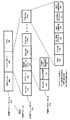
図2は、ある例示的な実施形態における、IEEE 802.11nパワーセーブマルチポール(PSMP)管理フレーム200のような、マルチポールメッセージのフォーマットを示す図である。管理アクションフレーム201は、例えば、MAC(media access control: 媒体アクセス制御)アドレス情報および他のフィールド、フレームボディ204およびフレームチェックシーケンス(FCS)206を含むことが可能なMACヘッダー202を含むことが可能である。ある例示的な実施形態では、フレームボディ204は、パワーセーブマルチポール(PSMP)フレームボディとすることが可能である。フレームボディ204は、例えば、高スループット(High Throughput: HT)(例、HTまたはIEEE 802.11n関連のフレーム)を示す値に設定した、カテゴリフィールド210を含むことが可能である。フレームボディ204は、PSMPフレームを示す値に設定したアクションフィールド212も含むことが可能である。
FIG. 2 is a diagram illustrating the format of a multi-pole message, such as an IEEE 802.11n power save multi-pole (PSMP)
フレームボディ204は、PSMPパラメータセット214および1つ以上の局情報フィールド(station information fields: STA Infoフィールド)216を含むことが可能である。PSMPパラメータセット214は、フレームボディ204内に存在する複数の局情報フィールド(STA Infoフィールド)を示す、複数の局(N_STA)フィールド215を含むことが可能である。さらに、More PSMPフィールド219を、例えば、一般的にこのPSMPシーケンスの後に別のPSMPシーケンスを続けることが可能であることを示すように、1に設定することが可能である。別様には、More PSMP 219を、このサービス期間中の最後のPSMPシーケンスであることを示すように、0に設定することが可能である。ある例示的な実施形態においては、PSMPシーケンスは、例えば、PSMPフレームに示されているように、1つ以上の局とやり取り(ダウンリンクおよび/またはアップリンク)するように、スケジュールされたデータ伝送が後に続くPSMPフレームを含むことが可能である。PSMPシーケンス持続時間フィールド221は、PSMPフレームによって記述された現在のPSMPシーケンスの持続時間を示す。
The
上述のように、APは、1つ以上の局情報(STA Info)フィールド216で提供される情報に基づいて、例えば、1つ以上のSTA Infoフィールド216を経て提供される伝送スケジュールに従って、複数の局へ伝送する、および/または複数の局から受信することが可能である。1つ以上のSTA Infoフィールド216で提供される情報は、一般的に、スケジュールまたは伝送スケジュールと称することが可能である。STA Infoフィールドは、(現在のPSMPシーケンスに対して)アップリンクおよび/またはダウンリンク伝送がPSMPメッセージによってスケジュールされる、各局に提供することが可能である。STA Infoフィールドの数は、N_STAフィールド215によって示される。したがって、図2に示されるPSMPフレームボディ204は、一例として、STA Infoフィールド216A、216B、...、216Zのような、1つ以上のSTA Infoフィールドを含むことが可能である。
As described above, the AP may be configured based on information provided in one or more station information (STA Info) fields 216, eg, according to a transmission schedule provided via one or more STA Info fields 216. It can be transmitted to a station and / or received from multiple stations. Information provided in one or more STA Info fields 216 can generally be referred to as a schedule or transmission schedule. The STA Info field may be provided for each station where uplink and / or downlink transmissions are scheduled by PSMP messages (for the current PSMP sequence). The number of STA Info fields is indicated by the
各STA Infoフィールド216は、複数のフィールドを含むことができる。STA Infoフィールド216は、トラフィックストリーム識別子(traffic stream identifier: TSID)フィールド223を含むことが可能であり、例えば、局が、スケジュールされたアップリンクデータ伝送のためのAPへのデータ伝送に使用することが可能であるか、または使用しなければならない1つ以上のTSIDを識別することが可能である。局識別子(STA ID)フィールド225は、(例えば、局のMACアドレスの一部または局に対するAIDを使用して)局を識別することが可能である。必須ではないが、ある例示的な実施形態では、STA Infoフィールド216内のSTA IDフィールド225を、マルチキャスト伝送を示すようにゼロに設定することが可能である。加えて、STA IDフィールド225は、ブロードキャスト伝送を示すように全て1に設定することも可能である。TSIDフィールド223およびSTA IDフィールド225は、必ずしも、マルチキャスト伝送のスケジューリングに適用可能であるとは限らない(例えば、アップストリームTSIDは、ダウンストリームマルチキャスト伝送に適用不可能であり、マルチキャストフレームは、一般的に、複数の受信器ノードに導かれるので、1つのSTA IDでは不十分となる)。
Each
ダウンリンク伝送(DLT)開始オフセットフィールド227は、スケジュールされたダウンリンクデータ伝送(APから局まで)に対する開始時間を示すことが可能であり、ダウンリンク伝送(DLT)持続時間フィールド229は、スケジュールされたダウンリンク伝送に対する持続時間を示すことが可能である。これら2つのDLT関連のフィールド(227、229)は、ユニキャスト伝送(例えば、単一の受信器ノードへの伝送)、およびマルチキャスト伝送(マルチキャストは、例えば、APから複数の受信器ノードまたは局へのダウンリンクデータ伝送とすることが可能である)の両方に適用することが可能である。 Downlink transmission (DLT) start offset field 227 can indicate the start time for scheduled downlink data transmission (from AP to station), and downlink transmission (DLT) duration field 229 can be scheduled. It is possible to indicate the duration for downlink transmission. These two DLT-related fields (227, 229) are unicast transmission (eg transmission to a single receiver node) and multicast transmission (multicast is eg AP to multiple receiver nodes or stations). It is possible to apply to both of them.
アップリンク伝送(ULT)(局からAPまで)開始オフセットフィールド231およびULT持続時間フィールド233は、STA Infoフィールド216内に提供され、ノードまたは局のためのスケジュールされたアップリンクデータ伝送に対する開始時間および持続時間を通信する。
Uplink transmission (ULT) (station to AP) start offset field 231 and ULT duration field 233 are provided in the
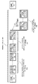
図3は、ある例示的な実施形態における、PSMPシーケンスを示す図である。図3では、PSMPシーケンス301は、例えば、PSMPフレーム302の伝送に続けて、1つ以上の受信器ノードへのスケジュールされたダウンリンクブロードキャストおよび/またはマルチキャストデータ伝送期間309と、1つ以上の受信器ノードへのスケジュールされたダウンリンクユニキャストデータ伝送期間311と、1つ以上の受信器ノードからのスケジュールされたアップリンクユニキャスト伝送期間315とを含むことが可能である。ある例示的な実施形態では、アップリンク伝送(315)を、ダウンリンク伝送(309および/または311)の後にスケジュールすることが可能である。移行317は、ダウンリンク伝送(DLT)(例、309、311)からアップリンク伝送(ULT)315までを示す。DLTからULTへの移行は、PSMPシーケンス301に対するダウンリンク伝送(例、309、311)が完了した後、かつシーケンス301に対するアップリンク伝送(315)が始まった直後のポイントとすることが可能である
FIG. 3 is a diagram illustrating a PSMP sequence in an exemplary embodiment. In FIG. 3, the PSMP sequence 301 includes, for example, transmission of a PSMP frame 302 followed by a scheduled downlink broadcast and / or multicast
PSMPフレーム302では、TSIDフィールド223は、例えば、受信器ノードが、スケジュールされたアップリンクユニキャストデータ伝送期間315中にフレームを伝送することが可能な、トラフィックストリームを示すことが可能である。STA IDフィールド225は、受信器ノードの(または受信器ノードを識別する)ためのAIDを含むことが可能である。DLTフィールド227および229を、識別された受信器ノードへのスケジュールされたダウンリンクユニキャストデータ伝送期間311に対する、開始時間および持続時間をそれぞれ示す値に設定することが可能である。同様に、PSMPフレーム302内のULTフィールド231および233を、(例えばSTA IDによって)識別された受信器ノードに提供されたスケジュールされたアップリンクユニキャストデータ伝送に対する、開始時間および持続時間をそれぞれ示す値に設定することが可能である。
In the PSMP frame 302, the
APは、PSMPフレーム302を伝送した後に、DLTの一部として1つ以上のダウンリンクフレームを(例えば、介在フレーム無しで)直ちにまたは実質的に直ちに伝送することが可能である。例えば、APは、PSMPフレーム302の直後に、スケジュールされたダウンリンクブロードキャスト/マルチキャストデータ伝送期間309に対する、1つ以上のブロードキャストおよび/またはマルチキャストフレーム(304、306、...)を伝送することが可能である。したがって、ある例示的な実施形態においてはおいて、例えば、各受信器ノードは、この時点でブロードキャストおよび/またはマルチキャストデータ伝送を承知または予測することが可能であるように、デフォルトのスケジューリングとして、ダウンリンクブロードキャストおよび/またはマルチキャストデータフレームを、PSMPフレーム302の伝送の直後に伝送することが可能である。ある例示的な実施形態では、ブロードキャストデータフレームは、マルチキャストデータフレームの前にスケジュールすることが可能である。別の実施形態では、マルチキャストデータフレームは、ブロードキャストデータフレームの前にスケジュールすることが可能である。さらに別の実施形態では、ブロードキャストデータフレームおよびマルチキャストデータフレームのスケジューリングを、互いに散在させることが可能である。
After transmitting the PSMP frame 302, the AP can transmit one or more downlink frames as part of the DLT (eg, without intervening frames) immediately or substantially immediately. For example, the AP may transmit one or more broadcast and / or multicast frames (304, 306, ...) for the scheduled downlink broadcast / multicast
マルチキャスト伝送の場合、専用のSTA Infoフィールド216を使用してマルチキャスト伝送を示すことができる。この場合、TSIDフィールド223を、スケジュールされたアップリンク伝送を有する受信器ノードがマルチキャスト伝送を返送することを示すように、1または他の特定の値に設定することが可能である。この状況では、STA IDフィールド225は、0に設定することが可能である。ある例示的な実施形態では、ブロードキャスト/マルチキャスト伝送のために、DLTフィールド227および229を使用して、ダウンリンクマルチキャスト伝送期間またはスケジュールを通信することが可能であり、ULTフィールド231および233を、0(または任意)に設定することが可能である。しかし、これらは単なる実施例であり、種々の実施形態はそれらに制限されるものではない。
For multicast transmission, a dedicated
ある例示的な実施形態では、例えば、このPSMPシーケンスに対して、APから伝送すべきいかなるダウンリンクブロードキャスト/マルチキャストフレームも無い場合は、PSMPフレームの後に、スケジュールされたダウンリンクユニキャストデータ伝送311を開始することが可能である。または、別の実施形態では、例えば、PSMPフレームの後にダウンリンクユニキャスト伝送(311)を開始することが可能であり、ブロードキャスト/マルチキャストダウンリンク伝送(309)を、ダウンリンクユニキャスト伝送(311)の後にすることが可能である。
In an exemplary embodiment, for example, if there is no downlink broadcast / multicast frame to be transmitted from the AP for this PSMP sequence, a scheduled downlink
次に、図3を参照する。1つ以上のユニキャストフレーム(例、フレーム308、310、312、314)を、スケジュールされたダウンリンクユニキャストデータ伝送期間311およびスケジュールされたアップリンクユニキャストデータ伝送期間315の一部として、1つ以上の受信器ノード(例、"ノード1"、"ノード2"、"ノード3")に伝送、およびこれらから受信することが可能である。ユニキャストフレームを、PSMPが可能な局(例、本実施形態では、"ノード1"、"ノード2"、および"ノード3")に伝送、および/またはこれらから受信する状況では、ユニキャストフレームのフレームの伝送は、PSMPシーケンス301の間に、PSMPケーブルが可能な局に対するオン/オフ移行の数を減じるように、および/またはノードのDLT期間とULT期間との間の遅延を増加させるように、PSMPフレーム内にスケジュールすることが可能である。このようにノードに対するDLTおよびULT期間をスケジュールすることによって、所与のPSMPシーケンス中に、PSMPが可能な局に対する"アウェイク時間"(例えば、全電力モードで動作する時間)を低減することが可能である。したがって、PSMPが可能な局に対する消費電力は、例えば、下述のスケジューリング手法を用いて低減することが可能である。一般的に、DLTは、局またはノードがAPまたは他の局からデータを受信することが可能な期間とすることが可能である。ULTは、局が、媒体を通じてデータをAPまたは他の局に送信することが可能な期間である。
Reference is now made to FIG. One or more unicast frames (eg, frames 308, 310, 312, 314) as part of a scheduled downlink unicast
オン/オフ動作の移行は、例えば、動作モード(例、全電力モード)から低電力モード(例、待機/スリープモード)への移行、およびこの逆とすることが可能である。説明のために、オン/オフ動作の移行は、(i)動作モードから待機モードへの移行、および(ii)待機モードから動作モードへの移行のことを、代替可能に指すことが可能である。本願明細書に記述された実施形態に従ってフレームの伝送をスケジュールすることによって、PSMP局に対するオン/オフ動作の移行の数を低減することが可能である。同様に、当該のPSMP局が低電力モード(例、待機モード)にある時間は、本願明細書に記述された実施形態に従ってユニキャストフレームの伝送をスケジュールすることによって増加させることが可能である。 The transition of the on / off operation can be, for example, a transition from an operation mode (eg, full power mode) to a low power mode (eg, standby / sleep mode) and vice versa. For the sake of illustration, the transition of on / off operation can alternatively refer to (i) transition from operating mode to standby mode, and (ii) transition from standby mode to operating mode. . By scheduling transmission of frames in accordance with the embodiments described herein, it is possible to reduce the number of on / off operation transitions for PSMP stations. Similarly, the time that the PSMP station is in a low power mode (eg, standby mode) can be increased by scheduling transmission of unicast frames according to the embodiments described herein.
図3に示される例示的な実施形態では、3つのPSMP局(ノード1、ノード2、およびノード3)が、PSMPシーケンス301中の伝送のためにスケジュールされたユニキャストフレームを有する。例えば、本実施例では、ノード1は、ダウンリンクユニキャストフレーム308のスケジュールされた伝送だけを有し、ノード3は、アップリンクユニキャストフレーム314だけのスケジュールされた伝送だけを有する。ノード2は、相対的に、ダウンリンクユニキャストフレーム310のスケジュールされた伝送と、スケジュールされたアップリンクユニキャストフレーム312とを有する。これは、単なる説明的または例示的な実施形態である。更なるノードまたはより少ないノードがデータ伝送のためにスケジュールされているか、または更なるフレームを伝送することが可能な、他の実施形態が存在する。さらに、所与のノードへの、および/またはこのノードからの伝送のためにスケジュールされたデータのタイプ、およびデータ伝送のためのスケジュールは、PSMPシーケンスによって様々であると理解されよう。
In the exemplary embodiment shown in FIG. 3, three PSMP stations (
ある例示的な実施形態においては、PSMPシーケンス中に、スケジュールされたダウンリンク伝送だけを有する1つ以上のノードの場合、これらのノードは、ダウンリンク伝送311の開始時またはほぼ開始時にダウンリンク伝送を行うようにスケジュールすることが可能である。例えば、図3に示されるように、ノード1に対するダウンリンクユニキャストフレーム308の伝送は、ダウンリンクユニキャストデータ伝送期間311の始め、またはほぼ始めにスケジュールされている。必須ではないが、ダウンリンク伝送は、実質的に、PSMPフレーム302の直後に、またはブロードキャスト/マルチキャスト伝送309の後にスケジュールすることが可能である。この状況では、ノード1は、ユニキャストフレーム308を受信した後に、PSMPシーケンス301の残りを低電力状態にすることが可能である。ある例示的な実施形態では、ノード1を、ブロードキャスト/マルチキャストデータ伝送期間309中に全電力(アウェイク)モードで動作させて、ダウンリンク伝送(例、フレーム308)を受信し、次いで低電力モードにすることが可能である。
In an exemplary embodiment, for one or more nodes that have only scheduled downlink transmissions during the PSMP sequence, these nodes transmit downlink transmissions at or near the beginning of
ダウンリンクユニキャスト伝送期間311の始め、またはほぼ始めにユニキャストフレーム308の伝送をスケジュールすることによって、オン/オフ動作の移行の数、およびノード1がアウェイクに費やす時間を低減することが可能である。例えば、DLT 311の中間または終わりまでノード1に対するフレーム308のダウンリンク伝送を遅延させることによって、一般的にノード1が全出力モードで動作する期間が増加するので、一般的にノード1に対する消費電力が増加する。別様には、ノード1は、更なるオン/オフ動作の移行を経て、例えば、ブロードキャスト/マルチキャストデータ伝送期間309の後に待機モードにさせて、ユニキャストフレーム308のスケジュールされたダウンリンクユニキャスト伝送時またはその直前に、アウェイク(全電力)モードに戻すことが可能である。しかし、当該の手法は、例えば、場合によっては、ダウンリンク伝送311の始めまたはほぼ始めに、ノード1のためのDLT(例、フレーム308)をスケジュールするよりも、場合によっては電力効率が劣る場合がある。
By scheduling the transmission of unicast frame 308 at or near the beginning of downlink
別の例示的な実施形態においては、PSMPシーケンス中に、スケジュールされたアップリンク伝送だけを有する1つ以上のノードのために、これらのノードを、アップリンク伝送315の終了時またはほぼ終了時にアップリンク伝送を行うようにスケジュールすることが可能である。例えば、ノード3は、アップリンクデータ伝送(例、フレーム314)に対してのみスケジュールされている。したがって、ノード3のためのアップリンクユニキャストフレーム314の伝送を、アップリンクユニキャストデータ伝送期間315の終了時またはほぼ終了時にスケジュールすることが可能である。この状況では、ノード3を、ブロードキャスト/マルチキャストデータ伝送期間309の後に低電力状態にし、ユニキャストフレーム314のスケジュールされたアップリンクユニキャスト伝送時または直前に全電力モードに戻るまで、ユニキャストデータ伝送期間311中に低電力状態のままにすることが可能である。ノード3は、次いで、例えば、フレーム314を伝送してから、次のPSMPフレームを受信する時間まで、低電力状態に戻しておくことが可能である。別の例示的な実施形態では、ノード3は、PSMPシーケンス301のブロードキャスト/マルチキャストデータ伝送期間309中に、ノード3に伝送すべきスケジュールされたデータが無い場合、または伝送すべきブロードキャストまたはマルチキャストフレームが無い場合、PSMPフレーム302を受信した後に、低電力モードにすることが可能である。
In another exemplary embodiment, during a PSMP sequence, for one or more nodes that have only scheduled uplink transmissions, these nodes are up at or near the end of
アップリンクユニキャスト伝送期間315の終了時またはほぼ終了時に、ユニキャストフレーム314(ノード3は、アップリンク伝送に対してのみスケジュールされている)の伝送をスケジュールすることによって、少なくとも場合によっては、オン/オフ動作の移行の数、およびノード3がアウェイク(または全電力モード)に費やす時間を低減することが可能である。例えば、ノード3がアップリンク伝送315の始めにアップリンク伝送を行うようにスケジュールされた場合、このことによって、ノード3が低電力状態に費やす時間を低減することが可能である。また、オン/オフ動作移行の時間が、ノードを待機(または低電力)状態よりも低電力STAへ移行させ、(ノードをアウェイクにすることが必要になる前に)作動状態へ戻すのに十分である場合、ノードはより低電力または深いスリープ状態へ移行し、さらなる節電が可能である。
At least in some cases, by scheduling transmission of unicast frame 314 (
ある例示的な実施形態では、ノード3は、複数の更なるオン/オフ動作の移行を経て、例えば、ブロードキャスト/マルチキャストデータ伝送期間309の後に待機モードにさせて、ユニキャストフレーム314のスケジュールされたアップリンクユニキャスト伝送時またはその直前に、アウェイク(全電力)モードに戻し、次いで、ユニキャストフレーム314を送信した後に低電力モードに戻すことが可能である。ノード3は、次いで、次のPSMPフレーム321の伝送時またはその直前に、別のオン/オフ動作の移行を経ることになる。図3に示される手法を使用すると、ノード3が、アップリンク伝送期間315の終了時またはほぼ終了時に、ユニキャストパケット314を伝送するので、次のPSMPフレーム321を受信するためにアウェイクのままにすることが可能となり、したがって、オン/オフ動作の移行の数が低減される。これは、別の例示的な実施形態である。
In an exemplary embodiment,
さらに別の例示的な実施形態では、PSMPシーケンス中に、(例、ユニキャスト)ダウンリンク伝送およびアップリンク伝送の両方のためにスケジュールされたノードに対して、これらのノードは、ダウンリンク伝送からアップリンク伝送へのほぼまたは移行317前後に、伝送を行うようにスケジュールすることが可能である。例えば、図3に示されるように、ノード2は、PSMPシーケンス301中に、ユニキャストダウンリンク伝送およびアップリンク伝送の両方のためにスケジュールされている。したがって、ノード2に対するダウンリンクユニキャストフレーム310の伝送およびアップリンクユニキャストフレーム312の伝送は、ダウンリンクユニキャストデータ伝送期間311と、アップリンクユニキャストデータ伝送期間315との間の移行時または移行の際(あるいは移行前後)にスケジュールすることが可能である。この状況では、ノード2は、例えば、ブロードキャスト/マルチキャストデータ伝送期間309の後(または、ブロードキャストまたはマルチキャストデータ伝送がスケジュールされない場合は、PSMPフレーム302を受信した後)に、低電力状態に入り、ダウンリンクユニキャスト伝送期間311の終了時またはほぼ終了時に、ユニキャストフレーム310のスケジュールされたダウンリンクユニキャスト伝送時または直前に、アウェイク(全電力)モードに戻るまで、ユニキャストダウンリンクデータ伝送期間311中のほとんどを、低電力状態のままとすることが可能である。ノード2は、次いで、アウェイクのままで、アップリンクユニキャストデータ伝送期間315の始めまたはほぼ始めに、アップリンクユニキャストフレーム312を伝送することが可能である。
In yet another exemplary embodiment, for nodes scheduled for both downlink and uplink transmissions (eg, unicast) during a PSMP sequence, these nodes It is possible to schedule the transmission to occur approximately or around 317 to the uplink transmission. For example, as shown in FIG. 3,
ダウンリンクユニキャスト伝送期間311の終了時またはほぼ終了時に、ダウンリンクユニキャストフレーム310の伝送をスケジュールし、アップリンクユニキャスト伝送期間315の始めまたはほぼ始めに、アップリンクユニキャストフレーム312の伝送をスケジュールすることによって、少なくとも場合によっては、オン/オフ動作の移行の数、およびノード2がアウェイクに費やす時間を低減することが可能である。例えば、ダウンリンクユニキャストデータ伝送期間311の中間またはほぼ始めにスケジュールされたダウンリンクユニキャストパケット310の伝送、およびアップリンクユニキャストデータ伝送の中間またはほぼ終了時にスケジュールされたアップリンクユニキャストパケット312の伝送の場合、ノード2は、その一部をアイドル状態(例えば、データを伝送も受信もしない)とすることが可能な間、より長い時間(例えば、スケジュールされた伝送の前および/または後)保持することが可能である。
At the end or near the end of the downlink
別様には、上述の状況では、ノード2は、複数の更なるオン/オフ動作の移行を経て、例えば、ブロードキャスト/マルチキャストデータ伝送期間309の後(または、PSMPフレーム302を受信した後)に待機モードにして、ユニキャストフレーム310のスケジュールされたダウンリンクユニキャスト伝送時またはその直前に、アウェイク(全電力)モードに戻すことが可能である。ノード2は、次いで、ユニキャストフレーム310を受信した後に低電力モードに戻し、ユニキャストフレーム312のスケジュールされたアップリンクユニキャスト伝送時またはその直前に、アウェイク(全電力)モードに戻すことが可能である。さらに、ノード2は、ユニキャストをフレーム314を伝送した後に低電力モードに戻すことが可能である。この状況では、ノード2は、次のPSMPフレーム321の伝送時またはその直前に、さらに別のオン/オフ動作の移行を経ることが可能である。図3に示される手法を使用すると、ノード3が、ダウンリンク伝送期間311とアップリンク伝送期間315との間の移行時または移行の前後に、ユニキャストパケット310を受信し、ユニキャストパケット312を伝送するので、ノード2は、単に、ユニキャストパケット310を受信した後にユニキャストパケット312を伝送するようにアウェイクのままにすることが可能となり、したがって、オン/オフ動作の移行の数が低減される。
Alternatively, in the situation described above,
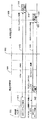
図4は、ダウンリンク伝送期間(DLT)のためのデータ伝送スケジュール、および例示的なPSMPシーケンスのためのアップリンク伝送期間(ULT)のある例示的な実施形態を示すタイミング図である。図4に示されるデータ伝送スケジュールは、PSMPフレーム402のようなフレーム(例、管理フレーム)内に含めることが可能である。図4の移行ポイント408は、例示的なデータ伝送スケジュールのためのDLT 404とULT 406との間の移行を示す。図4に示されるスケジュールでは、ブロードキャストおよび/またはマルチキャストデータのスケジューリングは示されていない。しかし、当該のスケジュールは、図3を参照して説明したものと同様に、ブロードキャストおよび/またはマルチキャストのスケジューリングを含むことが可能であると理解されよう。
FIG. 4 is a timing diagram illustrating an exemplary embodiment of a data transmission schedule for a downlink transmission period (DLT) and an uplink transmission period (ULT) for an exemplary PSMP sequence. The data transmission schedule shown in FIG. 4 can be included in a frame (eg, management frame) such as
図4に示されるデータ伝送スケジュールは、図3に示されるPSMPシーケンス301に類似する。相対的に、図4のデータ伝送スケジュールは、データ伝送期間(ダウンリンクおよびアップリンク)が、図3のノード2の場合と同じように、DLT404およびULT404の両方の間にスケジュールされている更なるノードを含む。したがって、図4のデータ伝送スケジュールは、PSMPが可能な4つの局、PSTA 1、PSTA 2、PSTA 3、およびPSTA 4のデータ伝送スケジュールを示す。上述のように、当該のデータ伝送スケジュールは、非PSMP局のためのデータ伝送のスケジューリングも含むことが可能である。なお、明確にするために、非PSMP局のためのデータ伝送のスケジューリングは示されていない。
The data transmission schedule shown in FIG. 4 is similar to the PSMP sequence 301 shown in FIG. Relative to the data transmission schedule of FIG. 4, the data transmission period (downlink and uplink) is further scheduled between both
図4のPSMPシーケンスの場合、PSTA 1は、DLT 404中にスケジュールされたダウンリンクユニキャストデータ伝送だけを有し、PSTA 2はULT 406中にスケジュールされたアップリンクユニキャストデータ伝送だけを有し、PSTA 3および4は(DLT 404中、およびULT 406中に)スケジュールされたダウンリンクおよびアップリンクユニキャストデータ伝送の両方を有する。図4に示されるように、PSTA 1乃至4は、PSMPフレーム402が通信している期間中に、すべてアウェイクとすることが可能である。PSMPフレーム402を受信した後に、PSTA 1乃至4は、次いで、図4に示されるデータ伝送スケジュールに従って動作させることが可能であり、PSMPフレーム402内に含めることが可能である。各PSTAに対するデータ伝送スケジュールを以下に順に説明する。
For the PSMP sequence of FIG. 4,
上述のように、PSTA 1は、図4に示されるPSMPシーケンス中にスケジュールされたダウンリンクユニキャストデータ伝送だけを有する。PSTA 1に対するダウンリンクユニキャストデータ伝送は、DLT 404の始め、またはほぼ始めにスケジュールされる。したがって、PSTA 1は、PSMPフレーム402を受信した後に、スケジュールされたダウンリンク伝送を受信するように、期間410中はアウェイクのままである。期間410の終わりに、PSTA 1に対するダウンリンク伝送が完了すると、PSTA 1は、期間412中に、待機(スリープ)モードにすることが可能であり、示されたPSMPシーケンスの残りに含めることが可能である。上述のように、当該の手法は、PSTA 1に対するオン/オフ動作の移行の数を低減し、またPSTA 1が待機に費やす時間を増加させることも可能である。これによって、PSTAは、待機(例、深いスリープ)よりも消費電力の少ない状態に移行し、ノードをアウェイクにすることが必要になる前に作動状態に移行することができる。これは、PSTAに更なる節電をもたらす。
As mentioned above,
図4では、上述のように、PSTA 2は、図4に示されるPSMPシーケンス中にスケジュールされたアップリンクユニキャストデータ伝送だけを有する。PSTA 1のためのアップリンクユニキャストデータ伝送は、ULT 406の終了時またはほぼ終了時にスケジュールされる。したがって、PSTA 2は、PSTA 2がPSMPフレーム402を受信する期間414の後に、待機モードとなり、スケジュールされたアップリンクユニキャストデータ伝送の直前まで待機モードのままとなる。例えば、期間418中に、PSTA 2がウェイクアップ(例えば、待機から全電力モードへ移行)する。PSTA 2は、次いで、期間420中に、スケジュールされたアップリンクユニキャストデータ伝送を完了する。PSTA 2に対するアップリンク伝送が期間420の終了時に完了すると、PSTA 2は、次のPSMPフレームを受信するようにアウェイクのままとすることが可能である。別様には、PSTA 2は、更なるPSMPシーケンスが生じない場合に、待機(スリープ)モードにすることが可能である。上述のように、当該の手法は、PSTA 2に対するオン/オフ動作の移行の数を低減し、またPSTA 2が待機に費やす時間を増加させることも可能である。
In FIG. 4, as described above,
さらに、図4では、上述のように、PSTA 3および4は、DLT 404およびULT 406中にスケジュールされた、ダウンリンクユニキャストデータ伝送期間およびアップリンクユニキャストデータ伝送期間を有する。図4に示されるように、PSTA 3および4に対しては、ダウンリンクユニキャストデータ伝送は、DLT 404の終了時またはほぼ終了時(例、移行ポイント408の直前)にスケジュールすることが可能であり、アップリンクユニキャストデータ伝送は、ULT 406の始め、またはほぼ始め(例、移行ポイント408の直後)にスケジュールすることが可能である。
Further, in FIG. 4, as described above, PSTAs 3 and 4 have downlink unicast data transmission periods and uplink unicast data transmission periods scheduled in
図4のPSTA 3は、PSTA 3がPSMPフレーム402を受信する期間422の後に、待機モードとなり、スケジュールされたアップリンクユニキャストデータ伝送の直前まで、期間424中に、待機モードのままとすることが可能である。例えば、期間426中に、PSTA 3がウェイクアップ(例えば、待機から全電力モードへ移行)する。PSTA 3は、次いで、期間428中に、スケジュールされたダウンリンクユニキャストデータ伝送を完了する。PSTA 3に対するアップリンク伝送期間を以下に説明する。
PSTA 3と同様に、図4のPSTA 4 は、期間434中にPSMPフレーム402を受信する。PSTA 4がPSMPフレーム402を受信すると、スケジュールされたダウンリンクユニキャストデータ伝送の直前まで、期間436中に、待機モードのままとすることが可能である。例えば、期間438中に、PSTA 4がウェイクアップ(例えば、待機から全電力モードへ移行)する。PSTA 4は、次いで、期間440中に、スケジュールされたダウンリンクユニキャストデータ伝送を完了する。
Similar to
図4に示されるように、移行408は、期間440中に生じる。したがって、PSTA 4は、スケジュールされたダウンリンクユニキャスト伝送を完了した後にアウェイクのままとし、また、期間440中に、スケジュールされたアップリンク伝送も完了することが可能である。期間440の終了時にPSTA 4のためのアップリンク伝送が完了すると、PSTA 4は、期間437中に、待機(スリープ)モードにすることが可能であり、示されたPSMPシーケンスの残りを含むことが可能である。
As shown in FIG. 4,
図4に示された実施形態の場合、PSTA 3は、期間432中に、アップリンク伝送を完了する。期間432は、期間440の実質的に直後に生じ、その間に、PSTA 4は、アップリンクおよびダウンリンクユニキャスト伝送を完了することが可能である。当該の機構によって、PSTAのためのデータ伝送のスケジューリングは、所与のPSMPシーケンス中に、スケジュールされたダウンリンクおよびアップリンクユニキャストデータ伝送の両方を有することができる。PSTA 3は、期間430中に(スケジュールされたダウンリンク伝送期間428とスケジュールされたアップリンクデータ伝送期間432のとの間)、作動させたままとすることが可能である。別様には、PSTA 3は、期間430中に、待機(スリープ)にすることが可能である。期間432の終了時にPSTA 3のためのアップリンク伝送が完了すると、PSTA 3は、期間425中に、待機(スリープ)モードにすることが可能であり、示されたPSMPシーケンスの残りを含むことが可能である。図4に示される手法を使用する(例えば、期間が移行ポイント408をブリッジするように、所与のPSMPシーケンス内にダウンリンクおよびアップリンクユニキャストデータ転送の両方を有するPSTAに対して、ダウンリンクおよびアップリンクユニキャストデータ伝送期間をスケジュールする)と、当該のPSTAに対するオン/オフ動作の移行の数が低減され、また当該のPSTAが待機(スリープ)モードに費やす時間を増加させることが可能である。
For the embodiment shown in FIG. 4,
図5は、所与のPSMPシーケンス内にダウンリンクおよびアップリンクユニキャストデータ転送の両方を有するPSTAに対して、ダウンリンクおよびアップリンクユニキャストデータ伝送期間をスケジュールするための、データ伝送スケジュールの別の例示的な実施形態を示すタイミング図である。図4のデータ伝送スケジュールと同様に、図5のスケジュールは、例示的なPSMPシーケンスのための、ダウンリンク伝送期間(DLT)504と、アップリンク伝送期間(ULT)506とを含む。図5のスケジュールは、PSMPフレーム502のようなフレーム(例、管理フレーム)内に含めることが可能である。図4と同様に、図5の移行ポイント508は、例示的なデータ伝送スケジュールのためのDLT 504とULT 506との間の移行を示す。また、図5に示されるスケジュールでは、ブロードキャストおよび/またはマルチキャストデータのスケジューリングは示されていない。しかし、これらのスケジュールは、図3を参照して説明したものと同様に、ブロードキャストおよび/またはマルチキャストのスケジューリングを含むことが可能であると理解されよう。
FIG. 5 illustrates another data transmission schedule for scheduling downlink and uplink unicast data transmission periods for PSTAs that have both downlink and uplink unicast data transmission within a given PSMP sequence. FIG. 6 is a timing diagram illustrating an exemplary embodiment of the present invention. Similar to the data transmission schedule of FIG. 4, the schedule of FIG. 5 includes a downlink transmission period (DLT) 504 and an uplink transmission period (ULT) 506 for an exemplary PSMP sequence. The schedule of FIG. 5 can be included in a frame (eg, management frame) such as
図5は、2つのPSMPが可能な局、PSTA 1およびPSTA 2のためのデータ伝送スケジュールを示し、上述のように、いずれも示された特定のPSMPシーケンスのための、スケジュールされたダウンリンクおよびアップリンクユニキャストデータ伝送期間を有する。次に、図5内の各PSTAを説明する。図5の例示的な実施形態では、ダウンリンクおよびアップリンク伝送の両方を行うようにスケジュールすることが可能なノードまたは局は、ダウンリンク伝送(DLT)期間504の始まり、またはほぼ始まりにダウンリンク伝送を行うようにスケジュールすることが可能であり、アップリンク伝送(ULT)期間506の終了時またはほぼ終了時にアップリンク伝送を行うようにスケジュールすることが可能である。このように、オン/オフ動作の移行の数を低減し、局またはノードが全電力モードで作動する期間を低減することが可能である。
FIG. 5 shows a data transmission schedule for two PSMP capable stations,
図5のPSTA 1は、期間510中に、アウェイク(全電力モードで作動)する。期間510中に、PSTA 1は、PSMPヘッダー502を受信することが可能である。また、期間510中(例、実質的にPSMPヘッダー502の受信直後)に、PSTA 1は、スケジュールされたダウンリンクユニキャストデータ伝送を受信させる。スケジュールされたダウンリンクユニキャストデータ伝送を完了した後に、PSTA 1は、スケジュールされたアップリンクユニキャストデータ伝送期間516の直前まで、待機モードにすることが可能である。例えば、期間514中に、PSTA 1がウェイクアップ(例えば、待機から全電力モードへ移行)する。PSTA 1は、次いで、期間516中に、スケジュールされたアップリンクユニキャストデータ伝送を完了する。PSTA 1に対するアップリンクユニキャスト伝送が期間516の終了時に完了すると、PSTA 1は、次のPSMPフレームを受信するようにアウェイクのままとすることが可能である。別様には、PSTA 1は、更なるPSMPシーケンスが生じない場合に、待機(スリープ)モードにすることが可能である。
PSTA 1と同様に、図5のPSTA 2は、期間518中に、アウェイク(全電力モードで動作)することが可能である。期間518中に、PSTA 2は、PSMPヘッダー502を受信することが可能である。PSTA 2は、次いで、図5のPSTA 1がスケジュールされたユニキャストデータ伝送を完了している間に、期間520中(期間510の残りに対応させることが可能である)に、スタンバイモードにすることが可能である。別様には、図5のPSTA 2は、期間520中にアウェイクのままとし、スケジュールされたダウンリンクユニキャストデータ伝送期間522の直前にウェイクすることが可能である。スケジュールされたダウンリンクユニキャストデータ伝送を完了した後に、PSTA 2は、スケジュールされたアップリンクユニキャストデータ伝送期間528の直前まで、待機モードにすることが可能である。例えば、期間526中に、PSTA 2がウェイクアップ(例えば、待機から全電力モードへ移行)する。PSTA 2は、次いで、期間528中に、スケジュールされたアップリンクユニキャストデータ伝送を完了する。PSTA 2に対するアップリンク伝送が期間528の終了時に完了すると、PSTA 2は、次のPSMPフレームを受信するようにアウェイクのままとすることが可能である(図5には示さず)。別様には、PSTA 2は、図5に示されたPSMPシーケンスの終了まで、待機(スリープ)モードにすることが可能である。
Similar to
図6は、ある例示的な実施形態における、無線ノードの動作を示すフローチャートである。610で、基地局またはAP(実施例)のようなノードは、フレームシーケンス中における、無線ネットワークの1つ以上のノードのための複数のアップリンクおよび/またはダウンリンク伝送期間を特定するフレームを伝送することが可能である。フレームシーケンス内において、アップリンク伝送は、ダウンリンク伝送の後にスケジュールすることが可能である。図6のフローチャートは、1つの更なる動作620、630および/または640を含むことが可能である。
FIG. 6 is a flowchart illustrating the operation of a wireless node in an exemplary embodiment. At 610, a node, such as a base station or AP (example), transmits a frame that identifies multiple uplink and / or downlink transmission periods for one or more nodes of a wireless network in a frame sequence. Is possible. Within the frame sequence, uplink transmissions can be scheduled after downlink transmissions. The flowchart of FIG. 6 may include one
620で、フレームシーケンス中にスケジュールされたダウンリンク伝送だけを有する1つ以上のノードを、ダウンリンク伝送の開始時またはほぼ開始時にダウンリンク伝送を行うようにスケジュールすることが可能である。630で、フレームシーケンス中にスケジュールされたアップリンク伝送だけを有する1つ以上のノードを、アップリンク伝送の開始時またはほぼ開始時にアップリンク伝送を行うようにスケジュールすることが可能である。640で、フレームシーケンス中にスケジュールされたダウンリンクおよびアップリンク伝送の両方を有する1つ以上のノードを、ダウンリンクからアップリンクへの移行の際に伝送を行うようにスケジュールすることが可能である。データフレームは、次いで、PSMPフレーム内に含まれたデータ伝送スケジュールに従って伝送する(例えば、スケジュールに従ってダウンリンク伝送し、その後にアップリンク伝送する)ことが可能である。 At 620, one or more nodes that have only downlink transmissions scheduled during the frame sequence can be scheduled to perform downlink transmissions at or near the beginning of the downlink transmission. At 630, one or more nodes that have only uplink transmissions scheduled during the frame sequence can be scheduled to perform uplink transmissions at or near the beginning of the uplink transmission. At 640, one or more nodes that have both downlink and uplink transmissions scheduled during the frame sequence can be scheduled to transmit on transition from the downlink to the uplink. . The data frame can then be transmitted according to the data transmission schedule contained within the PSMP frame (eg, downlink transmission according to the schedule and then uplink transmission).
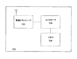
図7は、無線通信(例えば、ある例示的な実施形態における無線ノード)に提供することが可能な装置700を示すブロック図である。無線ノード(例、局またはAP)は、例えば、信号を送受信するための無線トランシーバ702と、局の動作を制御し、命令またはソフトウェアを実行するためのコントローラ704と、データおよび/または命令を格納するためのメモリ706とを含むことが可能である。
FIG. 7 is a block diagram illustrating an
無線ノードは、例えば図2に示されるPSMPフレームのような、管理フレームを受信すると、ノードは、PSMPフレーム200によって特定されたスケジュールに基づいて、ユニキャストトラフィック、マルチキャストおよび/またはブロードキャストトラフィックを受信するかどうかを決定することが可能である。当該のスケジュールは、例えば、上述の実施形態に従って実装することが可能である。無線局と送受信すべきトラフィックが無いことが特定された場合、無線局は、例えば当該のPSMPヘッダーを受信した後に、現在のフレームシーケンスに対して、電力を節約して低電力状態にすることができる。
When the wireless node receives a management frame, such as the PSMP frame shown in FIG. 2, for example, the node receives unicast traffic, multicast and / or broadcast traffic based on the schedule specified by the
コントローラ704は、プログラム可能であり、メモリまたは他のコンピュータ媒体に格納されるソフトウェアまたは他の命令を実行して、上述の様々なタスクおよび機能を実行することができる。例えば、コントローラ704は、PSMPフレームのような管理フレームを送信して、無線ネットワーク内の1つ以上の受信器ノードのそれぞれに対するスケジュールされたデータ伝送時間および命令を識別するようにプログラムすることが可能である。
The
ある例示的な実施形態では、コントローラ704または装置700は、フレームシーケンス中における、無線ネットワークの1つ以上のノードのための複数のアップリンクおよび/またはダウンリンク伝送期間を特定するフレームを送信することが可能である。アップリンク伝送は、ダウンリンク伝送の後に、前記フレームシーケンス内にスケジュールすることが可能である。ある実施形態では、フレームシーケンス中にスケジュールされたダウンリンク伝送だけを有する1つ以上のノードを、ダウンリンク伝送の開始時またはほぼ開始時にダウンリンク伝送を行うようにスケジュールすることが可能である。別の実施形態では、フレームシーケンス中にスケジュールされたアップリンク伝送だけを有する1つ以上のノードを、アップリンク伝送の終了時またはほぼ終了時にアップリンク伝送を行うようにスケジュールすることが可能である。さらに別の実施形態では、フレームシーケンス中にスケジュールされたダウンリンクおよびアップリンク伝送の両方を有する1つ以上のノードを、ダウンリンクからアップリンクへの移行の際に伝送を行うようにスケジュールすることが可能である。
In an exemplary embodiment, the
加えて、命令を格納した記憶媒体を備えることが可能であり、コントローラまたはプロセッサによって実行されたときに、コントローラ704、他のコントローラ、またはプロセッサは、上述の1つ以上の機能またはタスクを実行することが可能である。
In addition, a storage medium storing instructions can be provided, and when executed by the controller or processor, the
本願明細書に記述された種々の手法の実装形態は、デジタル電子回路に、またはコンピュータハードウェア、ファームウェア、ソフトウェアに、またはそれらを組み合わせたものに実装することが可能である。これらの実装形態は、データ処理装置、例えばプログラム可能なプロセッサ、単一のコンピュータ、または複数のコンピュータによって実行するための、またはその動作を制御するためのコンピュータプログラムとして、すなわち情報キャリア内に、例えば機械可読の記憶デバイスまたは伝播信号内に明白に組み込まれたコンピュータプログラムとして実装することが可能である。上述のコンピュータプログラムのようなコンピュータプログラムは、コンパイラまたはインタプリタ言語を含むあらゆる形態のプログラミング言語で作成することができ、また、スタンドアロンプログラムとして、またはモジュール、コンポーネント、サブルーチンとして、またはコンピューティング環境での使用に好適な他のユニットとしての形態を含む、あらゆる形態で導入することができる。コンピュータプログラムは、1つのサイトにおいて1つのコンピュータまたは複数のコンピュータ上で実行するか、または複数のサイトを通じて配信して、通信ネットワークによって相互接続するように導入することができる。 Implementations of the various techniques described herein can be implemented in digital electronic circuitry, or in computer hardware, firmware, software, or a combination thereof. These implementations may be implemented as data processing devices, e.g., programmable processors, single computers, or computer programs for execution by or controlling the operation thereof, i.e., in an information carrier, e.g. It can be implemented as a machine-readable storage device or a computer program that is explicitly incorporated within the propagated signal. Computer programs, such as the computer programs described above, can be created in any form of programming language, including compiler or interpreter languages, and used as stand-alone programs or as modules, components, subroutines, or in a computing environment It can be introduced in any form, including other suitable unit forms. The computer program can be implemented to run on one computer or multiple computers at one site, or be distributed through multiple sites and interconnected by a communication network.
方法ステップは、コンピュータプログラムを実行して、入力データで動作して結果を生成することによって機能を実行する、1つ以上のプログラム可能なプログラマブルプロセッサによって実行することが可能である。方法ステップはまた、専用ロジック回路、例えば、FPGA(field programmable gate array: フィールドプログラマブルゲートアレイ)、またはASIC(application-specific integrated circuit: 特定用途向け集積回路)によって実行すること、および前記回路として実装することが可能な装置によって実行することも可能である。 Method steps may be performed by one or more programmable programmable processors that perform functions by executing a computer program and operating on input data to produce a result. The method steps are also performed by and implemented as a dedicated logic circuit, eg, a field programmable gate array (FPGA), or an application-specific integrated circuit (ASIC). It is also possible to carry out by means of a possible device.
本願明細書に開示したように、記載した実施形態の特定の機能を例示したが、当業者は、多数の改良、置換、変更、および同等物を想起しうるであろう。したがって、添付の特許請求の範囲は、当該のすべての修正と変更を、種々の実施形態の真の精神の範囲内としてカバーすることを意図するものであると理解されたい。 While illustrated with the specific features of the described embodiments as disclosed herein, those skilled in the art will recognize numerous improvements, substitutions, changes, and equivalents. Therefore, it is to be understood that the appended claims are intended to cover all such modifications and changes as fall within the true spirit of the various embodiments.
Claims (29)
前記通信はフレームシーケンス単位で行われ、前記フレームシーケンスは、前記装置がブロードキャスト送信及び/又はマルチキャスト送信を行う第1の区間と、前記第1の区間の直後に設けられる一続きの区間であって、前記複数のノードのうち少なくともいくつかとの間のユニキャストダウンリンク通信を収容しうる第2の区間と、前記第2の区間の直後に設けられる一続きの区間であって、前記複数のノードのうち少なくともいくつかとの間のユニキャストアップリンク通信を収容しうる第3の区間とを有し、
前記装置が、前記第1の区間の間に、前記フレームシーケンス中における前記複数のノードのそれぞれのアップリンク通信期間および/またはダウンリンク通信期間を特定するスケジュールを含む、フレームを送信することを含み、ただし前記スケジュールにおいて、
前記複数のノードのうち、前記フレームシーケンス中でダウンリンク通信だけがスケジュールされるノードは、前記第2の区間の開始時またはその近辺にダウンリンク通信を行うようにスケジュールされる、方法。 A method in which a device schedules communication with a plurality of nodes that wirelessly communicate with the device,
The communication is performed in units of a frame sequence, and the frame sequence includes a first section in which the device performs broadcast transmission and / or multicast transmission, and a continuous section provided immediately after the first section. A second section capable of accommodating unicast downlink communication with at least some of the plurality of nodes, and a series of sections provided immediately after the second section, wherein the plurality of nodes A third leg capable of accommodating unicast uplink communications with at least some of
Including transmitting a frame including a schedule identifying an uplink communication period and / or a downlink communication period of each of the plurality of nodes in the frame sequence during the first interval. , However, in the schedule,
Wherein the plurality of nodes, the node only downlink communications are scheduled in the frame sequence is scheduled for downlink communications at the beginning or near the of the second section, methods.
前記通信はフレームシーケンス単位で行われ、前記フレームシーケンスは、前記装置がブロードキャスト送信及び/又はマルチキャスト送信を行う第1の区間と、前記第1の区間の直後に設けられる一続きの区間であって、前記複数のノードのうち少なくともいくつかとの間のユニキャストダウンリンク通信を収容しうる第2の区間と、前記第2の区間の直後に設けられる一続きの区間であって、前記複数のノードのうち少なくともいくつかとの間のユニキャストアップリンク通信を収容しうる第3の区間とを有し、
前記装置が、前記第1の区間の間に、前記フレームシーケンス中における前記複数のノードのそれぞれのアップリンク通信期間および/またはダウンリンク通信期間を特定するスケジュールを含む、フレームを送信することを含み、ただし前記スケジュールにおいて、
前記複数のノードのうち、前記フレームシーケンス中でダウンリンク通信およびアップリンク通信の両方がスケジュールされるノードは、前記第2の区間と前記第3の区間との境界またはその近辺に通信を行うようにスケジュールされる、方法。 A method in which a device schedules communication with a plurality of nodes that wirelessly communicate with the device,
The communication is performed in units of a frame sequence, and the frame sequence includes a first section in which the device performs broadcast transmission and / or multicast transmission, and a continuous section provided immediately after the first section. A second section capable of accommodating unicast downlink communication with at least some of the plurality of nodes, and a series of sections provided immediately after the second section, wherein the plurality of nodes A third leg capable of accommodating unicast uplink communications with at least some of
Including transmitting a frame including a schedule identifying an uplink communication period and / or a downlink communication period of each of the plurality of nodes in the frame sequence during the first interval. , However, in the schedule,
Among the plurality of nodes, said nodes both downlink and uplink communications in the frame sequence is scheduled, so that communicates to the boundary or near the said second section and said third section Scheduled on the way .
前記通信はフレームシーケンス単位で行われ、前記フレームシーケンスは、前記装置がブロードキャスト送信及び/又はマルチキャスト送信を行う第1の区間と、前記第1の区間の直後に設けられる一続きの区間であって、前記複数のノードのうち少なくともいくつかとの間のユニキャストダウンリンク通信を収容しうる第2の区間と、前記第2の区間の直後に設けられる一続きの区間であって、前記複数のノードのうち少なくともいくつかとの間のユニキャストアップリンク通信を収容しうる第3の区間とを有し、
前記装置が、前記第1の区間の間に、前記フレームシーケンス中における前記複数のノードのそれぞれのアップリンク通信期間および/またはダウンリンク通信期間を特定するスケジュールを含む、フレームを送信することを含み、ただし前記スケジュールにおいて、
前記複数のノードのうち、前記フレームシーケンス中でアップリンク通信だけがスケジュールされるノードは、前記第3の区間の終了時またはその近辺にアップリンク通信を行うようにスケジュールされる、方法。 A method in which a device schedules communication with a plurality of nodes that wirelessly communicate with the device,
The communication is performed in units of a frame sequence, and the frame sequence includes a first section in which the device performs broadcast transmission and / or multicast transmission, and a continuous section provided immediately after the first section. A second section capable of accommodating unicast downlink communication with at least some of the plurality of nodes, and a series of sections provided immediately after the second section, wherein the plurality of nodes A third leg capable of accommodating unicast uplink communications with at least some of
Including transmitting a frame including a schedule identifying an uplink communication period and / or a downlink communication period of each of the plurality of nodes in the frame sequence during the first interval. , However, in the schedule,
Wherein the plurality of nodes, the node only uplink communications in the frame sequence being scheduled is the third at the end or scheduled for uplink communication in the vicinity thereof of the interval methods.
前記通信はフレームシーケンス単位で行われ、前記フレームシーケンスは、前記装置がブロードキャスト送信及び/又はマルチキャスト送信を行う第1の区間と、前記第1の区間の直後に設けられる一続きの区間であって、前記複数のノードのうち少なくともいくつかとの間のユニキャストダウンリンク通信を収容しうる第2の区間と、前記第2の区間の直後に設けられる一続きの区間であって、前記複数のノードのうち少なくともいくつかとの間のユニキャストアップリンク通信を収容しうる第3の区間とを有し、
前記装置が、前記第1の区間の間に、前記フレームシーケンス中における前記複数のノードのそれぞれのアップリンク通信期間および/またはダウンリンク通信期間を特定するスケジュールを含む、フレームを送信することを含み、ただし前記スケジュールにおいて、
前記複数のノードのうち、前記フレームシーケンス中でダウンリンク通信だけがスケジュールされるノードは、前記第2の区間の開始時またはその近辺にダウンリンク通信を行うようにスケジュールされ、
前記複数のノードのうち、前記フレームシーケンス中でアップリンク通信だけがスケジュールされるノードは、前記第3の区間の終了時またはその近辺にアップリンク通信を行うようにスケジュールされ、
前記複数のノードのうち、前記フレームシーケンス中でダウンリンク通信およびアップリンク通信の両方がスケジュールされるノードは、前記第2の区間と前記第3の区間との境界またはその近辺に通信を行うようにスケジュールされる、方法。 A method in which a device schedules communication with a plurality of nodes that wirelessly communicate with the device,
The communication is performed in units of a frame sequence, and the frame sequence includes a first section in which the device performs broadcast transmission and / or multicast transmission, and a continuous section provided immediately after the first section. A second section capable of accommodating unicast downlink communication with at least some of the plurality of nodes, and a series of sections provided immediately after the second section, wherein the plurality of nodes A third leg capable of accommodating unicast uplink communications with at least some of
Including transmitting a frame including a schedule identifying an uplink communication period and / or a downlink communication period of each of the plurality of nodes in the frame sequence during the first interval. , However, in the schedule,
Wherein the plurality of nodes, the node only downlink communications are scheduled in the frame sequence is started or during scheduled for downlink communication in the vicinity thereof of the second section,
Wherein the plurality of nodes, the node only uplink communications in the frame sequence is scheduled is the third at the end or scheduled for uplink communication in the vicinity thereof of the section,
Among the plurality of nodes, said nodes both downlink and uplink communications in the frame sequence is scheduled, so that communicates to the boundary or near the said second section and said third section Scheduled on the way .
前記フレームシーケンスにおいてアップリンク通信だけがスケジュールされる前記ノードのうちの1つは、前記第3の区間の終了時にアップリンク通信を終了するようにスケジュールされ、 One of the nodes for which only uplink communication is scheduled in the frame sequence is scheduled to terminate uplink communication at the end of the third leg;
前記フレームシーケンス中でダウンリンク通信およびアップリンク通信の両方がスケジュールされる前記ノードの1つは、そのダウンリンク通信期間とアップリンク通信期間が、前記第2の区間と前記第3の区間との境界を跨いで連続するようにスケジュールされる、請求項9に記載の方法。 One of the nodes scheduled for both downlink communication and uplink communication in the frame sequence has a downlink communication period and an uplink communication period between the second period and the third period. The method of claim 9, wherein the method is scheduled to be continuous across a boundary.
前記アップリンク通信期間は、アップリンク開始オフセットおよび/またはアップリンク通信持続期間によって特定される、
請求項1から12のいずれかに記載の方法。The downlink communication period is specified by a downlink start offset and / or a downlink communication duration,
The uplink communication period is specified by an uplink start offset and / or an uplink communication duration.
The method according to any one of claims 1 to 12.
前記通信はフレームシーケンス単位で行われ、前記フレームシーケンスは、前記装置がブロードキャスト送信及び/又はマルチキャスト送信を行う第1の区間と、前記第1の区間の直後に設けられる一続きの区間であって、前記複数のノードのうち少なくともいくつかとの間のユニキャストダウンリンク通信を収容しうる第2の区間と、前記第2の区間の直後に設けられる一続きの区間であって、前記複数のノードのうち少なくともいくつかとの間のユニキャストアップリンク通信を収容しうる第3の区間とを有し、 The communication is performed in units of a frame sequence, and the frame sequence includes a first section in which the device performs broadcast transmission and / or multicast transmission, and a continuous section provided immediately after the first section. A second section capable of accommodating unicast downlink communication with at least some of the plurality of nodes, and a series of sections provided immediately after the second section, wherein the plurality of nodes A third leg capable of accommodating unicast uplink communications with at least some of
前記第1の区間の間に、前記フレームシーケンス中における前記複数のノードのそれぞれのアップリンク通信期間および/またはダウンリンク通信期間を特定するスケジュールを含む、フレームを送信するように構成される装置であって、前記スケジュールにおいて、 An apparatus configured to transmit a frame including a schedule identifying an uplink communication period and / or a downlink communication period of each of the plurality of nodes in the frame sequence during the first interval. In the schedule,
前記複数のノードのうち、前記フレームシーケンス中でダウンリンク通信だけがスケジュールされるノードは、前記第2の区間の開始時またはその近辺にダウンリンク通信を行うようにスケジュールする、装置。 An apparatus that, among the plurality of nodes, a node in which only downlink communication is scheduled in the frame sequence schedules to perform downlink communication at or near the start of the second interval.
前記通信はフレームシーケンス単位で行われ、前記フレームシーケンスは、前記装置がブロードキャスト送信及び/又はマルチキャスト送信を行う第1の区間と、前記第1の区間の直後に設けられる一続きの区間であって、前記複数のノードのうち少なくともいくつかとの間のユニキャストダウンリンク通信を収容しうる第2の区間と、前記第2の区間の直後に設けられる一続きの区間であって、前記複数のノードのうち少なくともいくつかとの間のユニキャストアップリンク通信を収容しうる第3の区間とを有し、 The communication is performed in units of a frame sequence, and the frame sequence includes a first section in which the device performs broadcast transmission and / or multicast transmission, and a continuous section provided immediately after the first section. A second section capable of accommodating unicast downlink communication with at least some of the plurality of nodes, and a series of sections provided immediately after the second section, wherein the plurality of nodes A third leg capable of accommodating unicast uplink communications with at least some of
前記第1の区間の間に、前記フレームシーケンス中における前記複数のノードのそれぞれのアップリンク通信期間および/またはダウンリンク通信期間を特定するスケジュールを含む、フレームを送信するように構成される装置であって、前記スケジュールにおいて、 An apparatus configured to transmit a frame including a schedule identifying an uplink communication period and / or a downlink communication period of each of the plurality of nodes in the frame sequence during the first interval. In the schedule,
前記複数のノードのうち、前記フレームシーケンス中でダウンリンク通信およびアップリンク通信の両方がスケジュールされるノードは、前記第2の区間と前記第3の区間との境界またはその近辺に通信を行うようにスケジュールする、装置。 Among the plurality of nodes, a node in which both downlink communication and uplink communication are scheduled in the frame sequence performs communication at or near the boundary between the second section and the third section. To schedule the equipment.
前記通信はフレームシーケンス単位で行われ、前記フレームシーケンスは、前記装置がブロードキャスト送信及び/又はマルチキャスト送信を行う第1の区間と、前記第1の区間の直後に設けられる一続きの区間であって、前記複数のノードのうち少なくともいくつかとの間のユニキャストダウンリンク通信を収容しうる第2の区間と、前記第2の区間の直後に設けられる一続きの区間であって、前記複数のノードのうち少なくともいくつかとの間のユニキャストアップリンク通信を収容しうる第3の区間とを有し、 The communication is performed in units of a frame sequence, and the frame sequence includes a first section in which the device performs broadcast transmission and / or multicast transmission, and a continuous section provided immediately after the first section. A second section capable of accommodating unicast downlink communication with at least some of the plurality of nodes, and a series of sections provided immediately after the second section, wherein the plurality of nodes A third leg capable of accommodating unicast uplink communications with at least some of
前記第1の区間の間に、前記フレームシーケンス中における前記複数のノードのそれぞれのアップリンク通信期間および/またはダウンリンク通信期間を特定するスケジュールを含む、フレームを送信するように構成される装置であって、前記スケジュールにおいて、 An apparatus configured to transmit a frame including a schedule identifying an uplink communication period and / or a downlink communication period of each of the plurality of nodes in the frame sequence during the first interval. In the schedule,
前記複数のノードのうち、前記フレームシーケンス中でアップリンク通信だけがスケジュールされるノードは、前記第3の区間の終了時またはその近辺にアップリンク通信を行うようにスケジュールする、装置。 An apparatus of the plurality of nodes, wherein a node in which only uplink communication is scheduled in the frame sequence schedules to perform uplink communication at or near the end of the third section.
前記通信はフレームシーケンス単位で行われ、前記フレームシーケンスは、前記装置がブロードキャスト送信及び/又はマルチキャスト送信を行う第1の区間と、前記第1の区間の直後に設けられる一続きの区間であって、前記複数のノードのうち少なくともいくつかとの間のユニキャストダウンリンク通信を収容しうる第2の区間と、前記第2の区間の直後に設けられる一続きの区間であって、前記複数のノードのうち少なくともいくつかとの間のユニキャストアップリンク通信を収容しうる第3の区間とを有し、 The communication is performed in units of a frame sequence, and the frame sequence includes a first section in which the device performs broadcast transmission and / or multicast transmission, and a continuous section provided immediately after the first section. A second section capable of accommodating unicast downlink communication with at least some of the plurality of nodes, and a series of sections provided immediately after the second section, wherein the plurality of nodes A third leg capable of accommodating unicast uplink communications with at least some of
前記第1の区間の間に、前記フレームシーケンス中における前記複数のノードのそれぞれのアップリンク通信期間および/またはダウンリンク通信期間を特定するスケジュールを含む、フレームを送信するように構成される装置であって、前記スケジュールにおいて、 An apparatus configured to transmit a frame including a schedule identifying an uplink communication period and / or a downlink communication period of each of the plurality of nodes in the frame sequence during the first interval. In the schedule,
前記複数のノードのうち、前記フレームシーケンス中でダウンリンク通信だけがスケジュールされるノードは、前記第2の区間の開始時またはその近辺にダウンリンク通信を行うようにスケジュールされ、 Among the plurality of nodes, a node in which only downlink communication is scheduled in the frame sequence is scheduled to perform downlink communication at or near the start of the second interval,
前記複数のノードのうち、前記フレームシーケンス中でアップリンク通信だけがスケジュールされるノードは、前記第3の区間の終了時またはその近辺にアップリンク通信を行うようにスケジュールされ、 Among the plurality of nodes, a node in which only uplink communication is scheduled in the frame sequence is scheduled to perform uplink communication at or near the end of the third section,
前記複数のノードのうち、前記フレームシーケンス中でダウンリンク通信およびアップリンク通信の両方がスケジュールされるノードは、前記第2の区間と前記第3の区間との境界またはその近辺に通信を行うようにスケジュールする、装置。 Among the plurality of nodes, a node in which both downlink communication and uplink communication are scheduled in the frame sequence performs communication at or near the boundary between the second section and the third section. To schedule the equipment.
前記フレームシーケンスにおいてアップリンク通信だけがスケジュールされる前記ノードのうちの1つは、前記第3の区間の終了時にアップリンク通信を終了するようにスケジュールされ、 One of the nodes for which only uplink communication is scheduled in the frame sequence is scheduled to terminate uplink communication at the end of the third leg;
前記フレームシーケンス中でダウンリンク通信およびアップリンク通信の両方がスケジュールされる前記ノードの1つは、そのダウンリンク通信期間とアップリンク通信期間が、前記第2の区間と前記第3の区間との境界を跨いで連続するようにスケジュールされる、請求項24に記載の装置。 One of the nodes scheduled for both downlink communication and uplink communication in the frame sequence has a downlink communication period and an uplink communication period between the second period and the third period. 25. The apparatus of claim 24, scheduled to be continuous across a boundary.
前記アップリンク通信期間は、アップリンク開始オフセットおよび/またはアップリンク通信持続期間によって特定される、 The uplink communication period is specified by an uplink start offset and / or an uplink communication duration.
請求項16から27のいずれかに記載の装置。28. Apparatus according to any of claims 16 to 27.
Applications Claiming Priority (2)
| Application Number | Priority Date | Filing Date | Title |
|---|---|---|---|
| US69122005P | 2005-06-16 | 2005-06-16 | |
| PCT/IB2006/001589 WO2006134472A2 (en) | 2005-06-16 | 2006-06-14 | Scheduling data transmissions to improve power efficiency in a wireless network |
Publications (3)
| Publication Number | Publication Date |
|---|---|
| JP2008544617A JP2008544617A (en) | 2008-12-04 |
| JP2008544617A5 JP2008544617A5 (en) | 2010-06-03 |
| JP4612090B2 true JP4612090B2 (en) | 2011-01-12 |
Family
ID=37532674
Family Applications (1)
| Application Number | Title | Priority Date | Filing Date |
|---|---|---|---|
| JP2008516439A Active JP4612090B2 (en) | 2005-06-16 | 2006-06-14 | Scheduling data transmission to improve power efficiency in wireless networks |
Country Status (12)
| Country | Link |
|---|---|
| US (2) | US7873018B2 (en) |
| EP (1) | EP1894353A4 (en) |
| JP (1) | JP4612090B2 (en) |
| KR (1) | KR100936190B1 (en) |
| CN (1) | CN101189833B (en) |
| BR (1) | BRPI0618086A8 (en) |
| MX (1) | MX2007014829A (en) |
| MY (1) | MY140948A (en) |
| SG (1) | SG162793A1 (en) |
| TW (1) | TWI317594B (en) |
| WO (1) | WO2006134472A2 (en) |
| ZA (1) | ZA200710453B (en) |
Families Citing this family (48)
| Publication number | Priority date | Publication date | Assignee | Title |
|---|---|---|---|---|
| US7873018B2 (en) | 2005-06-16 | 2011-01-18 | Nokia Corporation | Scheduling data transmissions to improve power efficiency in a wireless network |
| KR100615139B1 (en) * | 2005-10-18 | 2006-08-22 | 삼성전자주식회사 | Method and apparatus for allocating transmission period in wireless telecommunication system and therefor system |
| US7869390B2 (en) * | 2006-01-03 | 2011-01-11 | Samsung Electronics Co., Ltd. | Method and system for power save multi-poll (PSMP) communication in wireless systems |
| TWI452883B (en) * | 2006-02-14 | 2014-09-11 | Interdigital Tech Corp | Methods and systems for providing reliable multicast service in a wlan service |
| GB0609426D0 (en) * | 2006-05-12 | 2006-06-21 | Univ Edinburgh | A low power media access control protocol |
| WO2008057882A2 (en) * | 2006-11-07 | 2008-05-15 | Conexant Systems, Inc. | Systems and methods for management of wireless clients |
| US8462746B2 (en) | 2006-12-27 | 2013-06-11 | Altair Semiconductor Ltd. | Wireless receiver with intermittent shut-off of RF circuits |
| US7710939B2 (en) * | 2007-02-06 | 2010-05-04 | Samsung Electronics Co., Ltd. | Method and system for power saving in wireless local area communication networks |
| US8942150B2 (en) | 2007-03-19 | 2015-01-27 | Qualcomm Incorporated | Uplink timing control |
| US8270437B2 (en) * | 2007-06-18 | 2012-09-18 | Intel Corporation | Wireless network and method for communicating aggregated packets |
| US8694662B2 (en) | 2007-07-10 | 2014-04-08 | Qualcomm Incorporated | Method and apparatus for communicating transmission requests to members of a group and/or making group related transmission decisions |
| US7961698B2 (en) | 2007-07-10 | 2011-06-14 | Qualcomm Incorporated | Methods and apparatus for controlling interference to broadcast signaling in a peer to peer network |
| US8861418B2 (en) | 2007-07-10 | 2014-10-14 | Qualcomm Incorporated | Methods and apparatus for supporting group communications with data re-transmission support |
| US8495232B2 (en) * | 2007-07-10 | 2013-07-23 | Qualcomm Incorporated | Methods and apparatus for supporting broadcast communications in a peer to peer network |
| US8811373B2 (en) * | 2007-08-15 | 2014-08-19 | Qualcomm Incorporated | Rate matching of messages containing system parameters |
| WO2009057080A2 (en) * | 2007-11-01 | 2009-05-07 | Nokia Corporation | Wireless communication system featuring enhanced unscheduled automatic power save delivery |
| US20090154446A1 (en) * | 2007-12-14 | 2009-06-18 | Infineon Technologies Ag | Data frame, telegram, method for controlling an rf-transceiver and mobile communication system |
| JP2011523512A (en) * | 2007-12-24 | 2011-08-11 | アルタイル セミコンダクター リミテッド | Wireless receiver having intermediate cutoff function of RF circuit |
| US8824378B2 (en) * | 2008-02-01 | 2014-09-02 | Maarten Menzo Wentink | Unscheduled peer power save mode |
| US8477674B2 (en) * | 2008-03-12 | 2013-07-02 | Nokia Corporation | Wireless network including post groupcast time |
| US9088946B2 (en) | 2008-04-30 | 2015-07-21 | Qualcomm Incorporated | Methods and apparatus for power saving for mesh nodes |
| US9445253B2 (en) | 2008-04-30 | 2016-09-13 | Maarten Menzo Wentink | Methods and apparatus for scanning for mesh nodes |
| US8274894B2 (en) * | 2008-05-07 | 2012-09-25 | Nokia Corporation | Quality of service and power aware forwarding rules for mesh points in wireless mesh networks |
| JP2010016505A (en) * | 2008-07-02 | 2010-01-21 | Panasonic Corp | Control terminal, communication system, and communication control method |
| US8099197B2 (en) * | 2009-08-18 | 2012-01-17 | Enphase Energy, Inc. | Method and system for distributed energy generator message aggregation |
| US8542696B2 (en) | 2009-12-16 | 2013-09-24 | Intel Corporation | Device, system and method of simultaneously communicating with a group of wireless communication units |
| US20110149731A1 (en) | 2009-12-17 | 2011-06-23 | Gong Michelle X | Device, system and method of scheduling communications with a group of wireless communication units |
| KR101807725B1 (en) | 2010-03-09 | 2017-12-11 | 삼성전자주식회사 | Communication method of transmitting device and receiving device |
| US9265004B2 (en) | 2011-02-02 | 2016-02-16 | Altair Semiconductor Ltd | Intermittent shutoff of RF circuitry in wireless communication terminals |
| EP2700271B1 (en) | 2011-04-18 | 2017-08-23 | Marvell World Trade Ltd. | Reducing power consumption in an wireless communication system |
| US9088908B2 (en) | 2011-06-08 | 2015-07-21 | Marvell World Trade Ltd. | Efficient transmission for low data rate WLAN |
| GB201114079D0 (en) | 2011-06-13 | 2011-09-28 | Neul Ltd | Mobile base station |
| US9326238B2 (en) * | 2011-09-26 | 2016-04-26 | Broadcom Corporation | Smart meter media access control (MAC) for single user, multiple user, multiple access, and/or MIMO wireless communications |
| EP2761960A4 (en) * | 2011-09-30 | 2015-06-03 | Intel Corp | Scheduler system for simultaneous transmit and receive |
| CN103096440B (en) * | 2011-11-07 | 2019-01-25 | 中兴通讯股份有限公司 | A kind of wireless channel cut-in method and system |
| US9379868B2 (en) * | 2011-12-05 | 2016-06-28 | Broadcom Corporation | Subsequent association identifier (AID) update within single user, multiple user, multiple access, and/or MIMO wireless communications |
| CN103686934A (en) * | 2012-09-06 | 2014-03-26 | 华为技术有限公司 | Data receiving method and data sending method, and equipment |
| CN103781153A (en) * | 2012-10-23 | 2014-05-07 | 华为技术有限公司 | Definition method of element field and device |
| US20140192694A1 (en) * | 2013-01-08 | 2014-07-10 | Broadcom Corporation | Triggering downlink traffic with timing indication |
| US20140266625A1 (en) * | 2013-03-14 | 2014-09-18 | Qualcomm Incorporated | Assisted energy efficient peer-to-peer (p2p) communications |
| US9204385B2 (en) * | 2013-10-09 | 2015-12-01 | Netgear, Inc. | Wireless router or residential gateway capable of distinguishing power-sensitive wireless sensors and providing separate treatment thereto |
| WO2015194787A1 (en) * | 2014-06-19 | 2015-12-23 | 엘지전자 주식회사 | Method and apparatus for transmitting and receiving periodic data on basis of power save mode in wireless lan |
| WO2016152686A1 (en) | 2015-03-20 | 2016-09-29 | 株式会社 東芝 | Integrated circuit for wireless communication |
| CN106688283B (en) * | 2015-03-20 | 2020-08-07 | 株式会社东芝 | Integrated circuit for wireless communication and wireless communication method |
| US9973314B2 (en) * | 2015-04-06 | 2018-05-15 | Qualcomm Incorporated | Control frame aggregation frame |
| CN107534863B (en) * | 2015-07-08 | 2020-08-14 | 华为技术有限公司 | Resource scheduling method, device and equipment |
| US20170078967A1 (en) * | 2015-09-10 | 2017-03-16 | Qualcomm Incorporated | Efficiency and coexistence of wireless devices |
| US20200362987A1 (en) * | 2019-05-14 | 2020-11-19 | Washington Suburban Sanitary Commission | Valve position monitor, and systems and methods of using same |
Family Cites Families (31)
| Publication number | Priority date | Publication date | Assignee | Title |
|---|---|---|---|---|
| US6226277B1 (en) * | 1997-10-14 | 2001-05-01 | Lucent Technologies Inc. | Method for admitting new connections based on usage priorities in a multiple access system for communications networks |
| US6285665B1 (en) * | 1997-10-14 | 2001-09-04 | Lucent Technologies Inc. | Method for establishment of the power level for uplink data transmission in a multiple access system for communications networks |
| US6567416B1 (en) * | 1997-10-14 | 2003-05-20 | Lucent Technologies Inc. | Method for access control in a multiple access system for communications networks |
| JP3056199B1 (en) | 1999-02-25 | 2000-06-26 | 日本電気アイシーマイコンシステム株式会社 | Digital cordless telephone system |
| US6544548B1 (en) * | 1999-09-13 | 2003-04-08 | Keraplast Technologies, Ltd. | Keratin-based powders and hydrogel for pharmaceutical applications |
| US6670322B2 (en) * | 2000-06-01 | 2003-12-30 | Wisconsin Alumni Research Foundation | Method of targeting pharmaceuticals to motor neurons |
| US7062294B1 (en) * | 2000-09-29 | 2006-06-13 | Arraycomm, Llc. | Downlink transmission in a wireless data communication system having a base station with a smart antenna system |
| EP1227602A1 (en) * | 2001-01-24 | 2002-07-31 | Lucent Technologies Inc. | Method for dynamic allocation of timeslots in a TDD communication system |
| US6889056B2 (en) * | 2001-04-30 | 2005-05-03 | Ntt Docomo, Inc. | Transmission control scheme |
| JP2003037572A (en) * | 2001-07-23 | 2003-02-07 | Nec Corp | Scheduling system |
| US7184399B2 (en) | 2001-12-28 | 2007-02-27 | Intel Corporation | Method for handling completion packets with a non-successful completion status |
| US7110783B2 (en) * | 2002-04-17 | 2006-09-19 | Microsoft Corporation | Power efficient channel scheduling in a wireless network |
| US7177275B2 (en) * | 2002-07-26 | 2007-02-13 | Kenneth Stanwood | Scheduling method and system for communication systems that offer multiple classes of service |
| AU2002349425A1 (en) * | 2002-11-13 | 2004-07-14 | Zte Corporation | Forward-link rate scheduling method and scheduler |
| US7016319B2 (en) * | 2003-03-24 | 2006-03-21 | Motorola, Inc. | Method and apparatus for reducing co-channel interference in a communication system |
| US7508781B2 (en) * | 2003-03-25 | 2009-03-24 | Texas Instruments Incorporated | Power saving mechanism for wireless LANs via schedule information vector |
| US7321762B2 (en) | 2003-03-26 | 2008-01-22 | Conexant Systems, Inc. | Mechanism for reserving multiple channels of a single medium access control and physical layer |
| WO2005030119A2 (en) * | 2003-04-11 | 2005-04-07 | Allergan, Inc. | Botulinum toxin a peptides and methods of predicting and reducing immunoresistance to botulinum toxin therapy |
| CN1802801B (en) | 2003-05-27 | 2010-09-08 | 艾利森电话股份有限公司 | Scheduler and method of scheduling data for communication between a node station and plurality of radio terminals |
| US7457973B2 (en) * | 2003-06-20 | 2008-11-25 | Texas Instruments Incorporated | System and method for prioritizing data transmission and transmitting scheduled wake-up times to network stations based on downlink transmission duration |
| US7245946B2 (en) * | 2003-07-07 | 2007-07-17 | Texas Instruments Incorporated | Optimal power saving scheduler for 802.11e APSD |
| US7551948B2 (en) * | 2003-07-24 | 2009-06-23 | Cisco Technology, Inc. | Uniform power save method for 802.11e stations |
| JP4300931B2 (en) | 2003-08-07 | 2009-07-22 | ソニー株式会社 | WIRELESS COMMUNICATION SYSTEM AND METHOD, BASE STATION, MOBILE STATION, DATA TRANSMITTING AND RECEIVING METHOD, AND DATA TRANSMITTING AND RECEIVING PROGRAM |
| TW200515732A (en) | 2003-10-28 | 2005-05-01 | Groundhog Technologies Inc | Portable electronic device with wireless local area network unit |
| KR101071816B1 (en) * | 2004-04-02 | 2011-10-11 | 엘지전자 주식회사 | Method of scheduling of uplink packet in mobile packet communication system |
| US7555053B2 (en) * | 2004-04-14 | 2009-06-30 | Broadcom Corporation | Long training sequence for MIMO WLAN systems |
| GB2415573B (en) | 2004-06-21 | 2007-01-31 | Texas Instruments Inc | Optimal power saving scheduler for schedule information vector |
| US7477621B1 (en) * | 2004-09-07 | 2009-01-13 | Marvell International Ltd. | System and method for estimating bandwidth requirements of and allocating bandwidth to communication devices operating in a network |
| US7773569B2 (en) * | 2005-05-19 | 2010-08-10 | Meshnetworks, Inc. | System and method for efficiently routing data packets and managing channel access and bandwidth in wireless multi-hopping networks |
| US7873018B2 (en) | 2005-06-16 | 2011-01-18 | Nokia Corporation | Scheduling data transmissions to improve power efficiency in a wireless network |
| US8600336B2 (en) * | 2005-09-12 | 2013-12-03 | Qualcomm Incorporated | Scheduling with reverse direction grant in wireless communication systems |
-
2006
- 2006-06-13 US US11/452,082 patent/US7873018B2/en active Active
- 2006-06-14 WO PCT/IB2006/001589 patent/WO2006134472A2/en active Application Filing
- 2006-06-14 CN CN2006800191784A patent/CN101189833B/en active Active
- 2006-06-14 EP EP06755952A patent/EP1894353A4/en not_active Withdrawn
- 2006-06-14 MX MX2007014829A patent/MX2007014829A/en active IP Right Grant
- 2006-06-14 BR BRPI0618086A patent/BRPI0618086A8/en not_active Application Discontinuation
- 2006-06-14 KR KR1020077027921A patent/KR100936190B1/en active IP Right Grant
- 2006-06-14 JP JP2008516439A patent/JP4612090B2/en active Active
- 2006-06-14 SG SG201004198-6A patent/SG162793A1/en unknown
- 2006-06-15 TW TW095121480A patent/TWI317594B/en active
- 2006-06-16 MY MYPI20062864A patent/MY140948A/en unknown
-
2007
- 2007-11-30 ZA ZA200710453A patent/ZA200710453B/en unknown
-
2010
- 2010-12-08 US US12/963,032 patent/US8233876B2/en active Active
Also Published As
| Publication number | Publication date |
|---|---|
| WO2006134472A3 (en) | 2007-03-15 |
| BRPI0618086A8 (en) | 2016-05-10 |
| ZA200710453B (en) | 2008-11-26 |
| CN101189833A (en) | 2008-05-28 |
| US20110134821A1 (en) | 2011-06-09 |
| EP1894353A2 (en) | 2008-03-05 |
| US8233876B2 (en) | 2012-07-31 |
| TWI317594B (en) | 2009-11-21 |
| KR20080007490A (en) | 2008-01-21 |
| SG162793A1 (en) | 2010-07-29 |
| EP1894353A4 (en) | 2011-05-04 |
| TW200708013A (en) | 2007-02-16 |
| MX2007014829A (en) | 2008-02-15 |
| CN101189833B (en) | 2013-08-07 |
| MY140948A (en) | 2010-02-12 |
| WO2006134472A2 (en) | 2006-12-21 |
| JP2008544617A (en) | 2008-12-04 |
| US7873018B2 (en) | 2011-01-18 |
| US20060285517A1 (en) | 2006-12-21 |
| KR100936190B1 (en) | 2010-01-11 |
| BRPI0618086A2 (en) | 2011-08-16 |
Similar Documents
| Publication | Publication Date | Title |
|---|---|---|
| JP4612090B2 (en) | Scheduling data transmission to improve power efficiency in wireless networks | |
| EP1992095B1 (en) | Multicast address signaling for power save delivery in a wireless network | |
| JP4640812B2 (en) | Wireless communication apparatus and wireless communication method | |
| KR101158567B1 (en) | Deep sleep mode for mesh points | |
| CN102611996B (en) | The stand-by time of standing in wireless network is improved | |
| US8135427B2 (en) | Power save system and method | |
| US8477674B2 (en) | Wireless network including post groupcast time | |
| US20070201468A1 (en) | Multicast group address signaling using MAC header for power save delivery in a wireless network | |
| WO2021016766A1 (en) | Power conservation method and device, terminal, access network apparatus, and readable storage medium | |
| US9838963B2 (en) | Power efficient PS-Poll | |
| JP2010068111A (en) | Wireless communication base station, wireless communication terminal, wireless communication system, and wireless communication method | |
| Qin et al. | Cross-interface scheduling toward energy-efficient device-to-gateway communications in IoT | |
| Tanaka et al. | Automatic and cooperative sleep control strategies for power-saving in radio-on-demand WLANs | |
| US20220322227A1 (en) | A Technique for Skip Signal Transmission | |
| US9223744B1 (en) | Scheduled service periods in wireless mesh networks | |
| Israeli et al. | Experimental assessment of power-save behavior of commercial IEEE 802.16 network | |
| Sheu et al. | Smart merging strategy for configuring power saving parameters in IEEE 802.16 mobile WMANs |
Legal Events
| Date | Code | Title | Description |
|---|---|---|---|
| A521 | Request for written amendment filed |
Free format text: JAPANESE INTERMEDIATE CODE: A523 Effective date: 20100419 |
|
| A977 | Report on retrieval |
Free format text: JAPANESE INTERMEDIATE CODE: A971007 Effective date: 20100519 |
|
| A131 | Notification of reasons for refusal |
Free format text: JAPANESE INTERMEDIATE CODE: A131 Effective date: 20100527 |
|
| A521 | Request for written amendment filed |
Free format text: JAPANESE INTERMEDIATE CODE: A523 Effective date: 20100818 |
|
| TRDD | Decision of grant or rejection written | ||
| A01 | Written decision to grant a patent or to grant a registration (utility model) |
Free format text: JAPANESE INTERMEDIATE CODE: A01 Effective date: 20101012 |
|
| A01 | Written decision to grant a patent or to grant a registration (utility model) |
Free format text: JAPANESE INTERMEDIATE CODE: A01 |
|
| A61 | First payment of annual fees (during grant procedure) |
Free format text: JAPANESE INTERMEDIATE CODE: A61 Effective date: 20101014 |
|
| FPAY | Renewal fee payment (event date is renewal date of database) |
Free format text: PAYMENT UNTIL: 20131022 Year of fee payment: 3 |
|
| R150 | Certificate of patent or registration of utility model |
Ref document number: 4612090 Country of ref document: JP Free format text: JAPANESE INTERMEDIATE CODE: R150 Free format text: JAPANESE INTERMEDIATE CODE: R150 |
|
| R250 | Receipt of annual fees |
Free format text: JAPANESE INTERMEDIATE CODE: R250 |
|
| R250 | Receipt of annual fees |
Free format text: JAPANESE INTERMEDIATE CODE: R250 |
|
| S531 | Written request for registration of change of domicile |
Free format text: JAPANESE INTERMEDIATE CODE: R313531 |
|
| R350 | Written notification of registration of transfer |
Free format text: JAPANESE INTERMEDIATE CODE: R350 |
|
| R250 | Receipt of annual fees |
Free format text: JAPANESE INTERMEDIATE CODE: R250 |
|
| S111 | Request for change of ownership or part of ownership |
Free format text: JAPANESE INTERMEDIATE CODE: R313113 |
|
| R350 | Written notification of registration of transfer |
Free format text: JAPANESE INTERMEDIATE CODE: R350 |
|
| R250 | Receipt of annual fees |
Free format text: JAPANESE INTERMEDIATE CODE: R250 |
|
| R250 | Receipt of annual fees |
Free format text: JAPANESE INTERMEDIATE CODE: R250 |
|
| R250 | Receipt of annual fees |
Free format text: JAPANESE INTERMEDIATE CODE: R250 |
|
| R250 | Receipt of annual fees |
Free format text: JAPANESE INTERMEDIATE CODE: R250 |
|
| R250 | Receipt of annual fees |
Free format text: JAPANESE INTERMEDIATE CODE: R250 |
|
| R250 | Receipt of annual fees |
Free format text: JAPANESE INTERMEDIATE CODE: R250 |
|
| R250 | Receipt of annual fees |
Free format text: JAPANESE INTERMEDIATE CODE: R250 |
|
| R250 | Receipt of annual fees |
Free format text: JAPANESE INTERMEDIATE CODE: R250 |