JP4610341B2 - System and method for creating a custom-fitting artificial nail using a non-contact optical measurement device - Google Patents
System and method for creating a custom-fitting artificial nail using a non-contact optical measurement device Download PDFInfo
- Publication number
- JP4610341B2 JP4610341B2 JP2004552215A JP2004552215A JP4610341B2 JP 4610341 B2 JP4610341 B2 JP 4610341B2 JP 2004552215 A JP2004552215 A JP 2004552215A JP 2004552215 A JP2004552215 A JP 2004552215A JP 4610341 B2 JP4610341 B2 JP 4610341B2
- Authority
- JP
- Japan
- Prior art keywords
- nail
- artificial nail
- artificial
- dimensional shape
- natural
- Prior art date
- Legal status (The legal status is an assumption and is not a legal conclusion. Google has not performed a legal analysis and makes no representation as to the accuracy of the status listed.)
- Expired - Fee Related
Links
Images


Classifications
-
- A—HUMAN NECESSITIES
- A45—HAND OR TRAVELLING ARTICLES
- A45D—HAIRDRESSING OR SHAVING EQUIPMENT; EQUIPMENT FOR COSMETICS OR COSMETIC TREATMENTS, e.g. FOR MANICURING OR PEDICURING
- A45D31/00—Artificial nails
Landscapes
- Length Measuring Devices By Optical Means (AREA)
- Prostheses (AREA)
Abstract
Description
本発明は、一般的にはカスタムフィットする人工爪の作成に関し、具体的には人工爪をカスタムフィットさせるために爪を測定する非接触測定装置を用いて、カスタムフィットする人工爪を作成する方法及びシステムに関する。 The present invention relates generally to the creation of custom-fitting artificial nails, and more specifically, a method for creating a custom-fitting artificial nail using a non-contact measuring device that measures the nails to custom-fit the artificial nail. And the system.
魅力あるファッション用(同時に機能的ではないとすると)装身具である人工爪は、様々な形で存在する。特注生産の人工爪は、天然爪の正確な外形及び寸法に適合するように作成することができる。これにより、通常入手可能なカスタムフィットしない爪に比べて、快適さ、外観及び耐久性においてかなりの利点がもたらされる。しかし、人工爪をカスタムフィットさせることは、特別な課題と問題点とを提起する。通常用いられる人工爪の作成方法は、非常に労働集約的で、時間がかかり、しかもかなりの技術を必要とする。 Artificial nails that are attractive (and not functional at the same time) accessories exist in various forms. Custom-made artificial nails can be made to fit the exact outline and dimensions of natural nails. This provides significant advantages in comfort, appearance and durability over the commonly available non-custom-fitting nails. However, custom fitting artificial nails poses special challenges and problems. Commonly used methods for making artificial nails are very labor intensive, time consuming and require considerable skill.
人工爪の1つの作成方法は、「ネイルスカルプチャリング」と呼ばれている。この方法では、本物の指の先端に、接着剤あるいは支持シートによって既製の人工爪が取り付けられる。この支持シートは、指の先端のすぐ下に取り付けられ、次に熱硬化性材料(主にアクリル系)が、天然爪の甘皮から天然爪の上に少しずつ塗布され、人工爪全体あるいは支持シートの一部を覆うように形作られ、均一な延長面が形成される。この処理は、それぞれの指について繰り返される。熱硬化性材料が自然に、あるいは紫外線照明を当てられて乾燥すると、各爪について所望の形状を作るために、爪やすりによる集中的な研磨かけが施される。この方法は、材料を少しずつ手で加えることによって人工爪を作り上げるため、「ネイルスカルプチャ」と名付けられた。この製法の最後の工程は、所望の色あるいは模様を表すために、人工爪の上面にネイルポリッシュを塗ることである。 One method of creating an artificial nail is called “nail sculpting”. In this method, a ready-made artificial nail is attached to the tip of a real finger with an adhesive or a support sheet. This support sheet is attached just under the tip of the finger, and then a thermosetting material (mainly acrylic) is applied little by little from the natural nail cuticle onto the natural nail, and the entire artificial nail or support sheet Is formed so as to cover a part thereof, and a uniform extended surface is formed. This process is repeated for each finger. When the thermosetting material is dried naturally or under UV illumination, intensive polishing with a nail file is applied to create the desired shape for each nail. This method was named “nail sculpture” because it created an artificial nail by adding material by hand. The final step in the process is to apply nail polish to the top surface of the artificial nail to represent the desired color or pattern.
人工爪のもう1つの作成方法は、「ネイルラッピング」と呼ばれる。この方法では、繊維片を切り取って天然爪の上に接着する。何層かの繊維が接着及び乾燥された後、被膜あるいは充填材が施されて、連続した均一な表面が形成される。所望の形状を作るための集中的なやすりかけの後、爪を磨くことができる。この処理は、それぞれの爪に対して繰り返す必要がある。「ネイルスカルプチャリング」も「ネイルラッピング」も、利用者及び爪の専門家を、ガス、液体薬品およびやすりかけ屑にさらすため、健康上及び呼吸器の問題を生じさせ得る。更に、人工爪は取り付けられる際に天然爪の表面上に接着されているため、天然爪の伸びによって、甘皮と取り付けられた人工爪の間に隙間が生じてくる。この隙間は定期的に埋める必要があり、この処理には相当な時間とお金が必要である。 Another method of creating an artificial nail is called “nail wrapping”. In this method, the fiber pieces are cut and bonded onto the natural nails. After several layers of fibers are bonded and dried, a coating or filler is applied to form a continuous, uniform surface. After intensive filing to create the desired shape, the nails can be polished. This process needs to be repeated for each nail. Both “nail sculpting” and “nail wrapping” expose users and nail specialists to gas, liquid chemicals and filing debris, which can create health and respiratory problems. Furthermore, since the artificial nail is adhered on the surface of the natural nail when attached, a gap is formed between the cuticle and the attached artificial nail due to the elongation of the natural nail. This gap needs to be filled regularly, and this process requires considerable time and money.
ネイルスカルプチャリングやネイルラッピングに代わる、より安価な方法は、ネイルアートが既に施されていて、天然爪の上に貼り付けることができる既製の人工爪である。しかし、そうした大量生産による人工爪は、形、長さ、スタイル及び適合度において、選択の幅が限られている。人の爪は、甘皮、幅、長さ及び三次元(3D)形状において、他の人の爪と異なっている。従って、大量生産による人工爪は、利用者の天然爪に正確には適合し得ない。通常、このような人工爪は天然爪の表面に押し付けられ、接着剤で接着される。このため、人工爪が簡単にはがれるという問題が生じる。更に、このタイプの人工爪は、一般に、端部において形が適合しないため、偽物であることが分ってしまう。 A cheaper alternative to nail sculpting or nail wrapping is a ready-made artificial nail that has already been applied with nail art and can be affixed onto a natural nail. However, such mass-produced artificial nails have limited choices in shape, length, style and fit. Human nails differ from other human nails in cuticle, width, length and three-dimensional (3D) shape. Therefore, an artificial nail produced by mass production cannot accurately match a user's natural nail. Usually, such an artificial nail is pressed against the surface of a natural nail and bonded with an adhesive. For this reason, the problem that an artificial nail peels easily arises. Furthermore, this type of artificial nail is generally found to be fake because the shape does not fit at the ends.
上記のような従来の既製の人工爪、ネイルスカルプチャリング法及びネイルラッピング法の場合に直面する問題点を解消する他の選択肢は、全ての人工爪を特注生産することである。この方法は、天然爪の一連の正確なくぼみ型から石膏鋳型を作成することから成り、その鋳型を、射出成形あるいは鋳造によって人工爪を作成するのに用いることができる。この方法によって人工爪を作成するのも、大雑把な鋳造品から完成品に変えるための時間と費用がかかり、かなりの手間も要する。また、この方法をネイルサロンで実施するのは非現実的である。 Another option that eliminates the problems encountered with conventional off-the-shelf artificial nails, nail sculpting and nail wrapping methods as described above is to custom-manufacture all artificial nails. This method consists of creating a gypsum mold from a series of precise hollow molds of natural nails that can be used to create artificial nails by injection molding or casting. Producing an artificial nail by this method also takes time and cost to change from a rough cast product to a finished product, and requires considerable effort. Moreover, it is unrealistic to implement this method in a nail salon.
他の方法は、カスタムフィットするように爪を測定するため、その人の爪に接触することを必要とする。これらのシステムは、非接触測定システムよりも本質的に不正確であり、故障しやすい機械装置を必要とする。 Other methods require contacting the person's nails to measure the nails for a custom fit. These systems are inherently less accurate than non-contact measurement systems and require mechanical equipment that is prone to failure.
本発明によれば、好適な実施例は、カスタムフィットする人工爪を作成するための、人工爪作成システムを提供する。本発明の他の局面において、前記人工爪作成システムは、爪の寸法を側定する非接触測定システムを備え、前記非接触測定システムは、爪の三次元形状を測定するための非接触測定装置を備える。本発明の別の局面においては、爪の三次元形状を用いて人工爪を作成するための機械加工装置が用いられ、出来上がった人工爪は爪にカスタムフィットする。本発明の更に別の局面は、爪に白色灯を照射するための光源、及び爪の映像を記録するためのカメラを提供する。更に本発明の別の局面においては、三次元形状を計算するために、光源が爪の上にグリッドを投影し、グリッドの画像を撮影してもよい。別の実施例においては、爪の表面を走査するための光源としてレーザを使用することができる。光源の白色灯の実施例あるいはレーザの実施例から得られるデータは、爪についての三次元データ構造に変換される。本発明の更なる局面において、好適な実施例は、人工爪を特注デザインするための方法であって、非接触測定システムで爪の三次元形状を測定するステップと、人工爪の厚さ、長さ及びスタイルを含む人工爪のパラメータを選択するステップと、爪の三次元形状と人工爪用のパラメータから人工爪の三次元形状を計算するステップとを含む方法を提供する。好適な実施例において、この方法は、人工爪にカスタムフィットさせるために人工爪を機械加工することを含んでいる。 In accordance with the present invention, the preferred embodiment provides an artificial nail creation system for creating a custom-fitting artificial nail. In another aspect of the present invention, the artificial nail creation system includes a non-contact measurement system for determining a dimension of the nail, and the non-contact measurement system is a non-contact measurement device for measuring a three-dimensional shape of the nail. Is provided. In another aspect of the present invention, a machining device for creating an artificial nail using the three-dimensional shape of the nail is used, and the completed artificial nail is custom-fitted to the nail. Still another aspect of the present invention provides a light source for irradiating a nail with a white light and a camera for recording an image of the nail. Further, in another aspect of the present invention, in order to calculate a three-dimensional shape, a light source may project a grid on the nail and take an image of the grid. In another embodiment, a laser can be used as a light source for scanning the surface of the nail. Data obtained from the white light source embodiment or the laser embodiment is converted into a three-dimensional data structure for the nail. In a further aspect of the invention, a preferred embodiment is a method for custom designing an artificial nail, the step of measuring the three-dimensional shape of the nail with a non-contact measuring system, and the thickness, length of the artificial nail. A method is provided that includes selecting artificial nail parameters including height and style, and calculating a three-dimensional shape of the artificial nail from the three-dimensional shape of the nail and the parameters for the artificial nail. In a preferred embodiment, the method includes machining the artificial nail for a custom fit to the artificial nail.
稼動中、本発明の1つの局面に関するシステム利用者は、非接触測定装置が各指の爪の形状を測定する特注測定のために、1本あるいは複数の指を提示する。測定の結果もたらされたデータは、提案された人工爪と併せて利用者が見ることができるよう、三次元画像に変換される。次に、利用者は、特注の人工爪をデザインするための選択肢を選ぶことができる。所望の選択肢を選ぶと、その人工爪に関する三次元データが機械コードに変換され、素材からシステム利用者にカスタムフィットする所望の形状に人工爪を切削する、コンピュータ数値制御機などの機械に転送される。 In operation, a system user for one aspect of the present invention presents one or more fingers for a custom measurement in which the non-contact measuring device measures the shape of each fingernail. The data resulting from the measurement is converted into a three-dimensional image for viewing by the user in conjunction with the proposed artificial nail. The user can then choose an option to design a custom artificial nail. Once the desired option is selected, the 3D data about the artificial nail is converted into a machine code and transferred to a machine such as a computer numerical controller that cuts the artificial nail from the material into the desired shape that fits the system user. The
このように、迅速かつ正確に測定し、人工爪をカスタムフィットさせるシステム及び方法が提供されている。本システムは、短時間のうちに特注の爪のために測定し、特注の爪をデザインして作成する機会を提供する。本システムは、都合のよいことに小さく、特注の爪のデザインが既に提示されているサロンで使用するのに適している。 Thus, systems and methods are provided for quickly and accurately measuring and custom fitting artificial nails. The system provides an opportunity to design and create a custom nail, measuring for a custom nail in a short time. The system is conveniently small and suitable for use in a salon where a custom nail design has already been presented.
従って、本発明の効果は、非接触測定システムを備えた自動システムを用いて、特注生産の人工爪を作成するシステム及び方法を提供することである。本発明の別の効果は、天然爪の形状と寸法を測定し、カスタムフィットする人工爪を作成するための、安全で便利であり、正確かつ迅速なシステムを提供することである。本発明の更に別の効果は、天然爪のデジタル化された三次元形状を組み入れた人工爪を、デジタル的にデザインする方法を提供することである。 Accordingly, an advantage of the present invention is to provide a system and method for creating custom-made artificial nails using an automated system with a non-contact measurement system. Another advantage of the present invention is that it provides a safe, convenient, accurate and quick system for measuring the shape and dimensions of natural nails and creating custom-fitting artificial nails. Yet another advantage of the present invention is to provide a method for digitally designing artificial nails that incorporate the digitized three-dimensional shape of natural nails.
本発明の更なる適応範囲は、以下に提示されている詳細な説明から明らかになるであろう。 Further scope of applicability of the present invention will become apparent from the detailed description provided hereinafter.
以下の好適な実施例の説明は、本質的に単なる例示に過ぎず、決して本発明、本発明の利用法あるいは用途を限定するためのものではない。
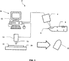
図1に関して、本発明の人工爪作成システム2は、指8の爪6の形状及び寸法を測定するための光学測定装置4を備える。光学測定装置4は、関連技術における当業者に公知である種類の装置である。例えば、光学測定装置は、「高速三次元表面測定、表面検査およびリバース−CADシステム」という名称の、米国特許No.5,175,601(参照により本明細書に組み込まれる。)に開示されている種類のものであってもよい。光学測定装置4は、コンピュータシステム12を含む測定デザインシステム10に接続されている。測定デザインシステム10は、台20の上に載せられた材料18を人工爪22に機械加工するための加工工具16を備えた、機械加工装置14に接続されている。一実施例における機械加工装置14は、関連技術の当業者に公知のコンピュータ数値制御(CNC)装置である。例えば、機械加工装置14は、「直線軸及び回転軸に沿って指示通りに被加工品を機械加工するために、工作機械を制御するための数値制御装置」という名称の、米国特許No.5,493,502(参照により本明細書に組み込まれる。)に開示されている種類のものであってもよい。コンピュータシステム12は、モニタ、キーボード及びマウス等のポインティングデバイスを取り付けたマイクロプロセッサベースのコンピュータである。コンピュータは、アプリケーションプログラムやデータを保存したり読み出したりするための、ハードドライブ及びRAMといった記憶装置を備える。
The following description of the preferred embodiment is merely exemplary in nature and is in no way intended to limit the invention, its use or uses.
With reference to FIG. 1, the artificial
次に図2について、人工爪作成システム2の光学測定装置4は、カメラ24、光源26及び投影レンズ28を備えている。カメラ24は、エリアタイプあるいはラインタイプ撮像装置としての撮像機能を有する、アナログあるいはデジタルビデオカメラである。光源26は、爪6の上にグリッド(図示されていない)を投影するための白色灯である。爪6の上にグリッドが投影されている間に、グリッドの写真を撮るためにカメラ24が用いられる。次に、爪6の三次元形状を計算するために、写真が測定デザインシステム10に転送される。
2, the
第二の好適な実施例において、光源26は、爪6の三次元形状を測定するために用いられるレーザである。本実施例において、レーザの光源26は爪6を横切る縞状に走査し、カメラ24がその画像を記録する。次に、レーザ三角測量アルゴリズムが用いられて、爪6の三次元形状が決定される。レーザ走査は、光源26を平行移動させるか、もしくは爪6を移動させることにより行うことができる。光源26を移動させず、爪6を横切るようにレーザを回転可能に走査するための鏡(図示されていない)を回転させることを含め、レーザの光源26で爪6を走査する他の方法を用いることも可能である。光源26の白色灯の実施例あるいは光源26のレーザの実施例のいずれにおいても、撮像及び走査処理は好都合なことに短時間で、人工爪作成システム2の利用者は、速やかに走査して、複数の爪の三次元形状を測定することができる。
In the second preferred embodiment, the
光源26の白色灯の実施例を用いる場合、爪6の上に投影されるグリッドは、爪6の形状に応じて変形する。爪6のグリッドの変形は、カメラ24により二次元のグリッド画像として記録される。この二次元の変形グリッド画像を爪6の三次元形状に復元するために、様々なアルゴリズムを用いることができる。二次元の変形グリッド画像を復元するためのアルゴリズムは、位相シフト、フーリエ変換、空間コード化、シヌソイド フィッティング等を含む。これらのアルゴリズムは、計算の最後に、グリッド画像の各ピクセルに対する三次元座標に変換された位相マップをもたらす。こうした計算は、測定デザインシステム10によって行われる。レーザ走査法及び白色灯グリッド法のどちらも、爪6の三次元形状を表す、公知のx、y及びz軸座標による一連の点を生成する。また、x、y及びz軸座標は、指8と爪6の境界を規定する。これらの非接触法を用いることにより、1つの爪について測定される点の総数は、容易に200,000を越え得る。x、y及びz軸座標は、コンピュータシステム12の記憶容量の範囲内で、デジタル形式で保存される。
When the embodiment of the white lamp of the
爪6の境界は、次の方法のうちの1つによって判断される。
(1)ポインティングデバイスを用いて、コンピュータモニタの画面上に、指8の爪6の輪郭を描くこと、あるいは
(2)境界抽出アルゴリズムによって、爪6の境界を自動的に判断すること。
どちらも、関連技術の当業者には周知の方法である。
The boundary of the
(1) The outline of the
Both are well known to those skilled in the relevant art.
図6に関して、非接触測定装置によりカスタムフィットする人工爪を作成する方法は、ステップ60において、爪6のより正確な測定を可能にするための爪6の処理から始まる。これは、余分な甘皮を除去し、爪6を適当な長さに切ることを含む。次に、ステップ62において、爪6は被覆剤で覆われる。この被覆剤は、爪6の上に光学的拡散面を形成するために施される。適当な被覆剤であれば、どのようなものでも用いることができる。適当な被覆剤は、例えばMagnaFluxTM社のSKD−S2である。爪6の上に被覆剤を施すステップ62は、必須のものではなく、省いてもよい。続いて、ステップ63においては、爪6の三次元形状を測定するため、爪6が光学測定装置4内に置かれる。ステップ64において光学測定装置4が駆動され、ステップ65において、爪6の上にグリッドあるいはレーザ光が投影されている間に、光学測定装置4がカメラ24で爪6を撮影する。ステップ66において、測定デザインシステム10が爪6に関するx、y及びz座標を計算する。最後に、ステップ67において、計算された座標が測定デザインシステム10のコンピュータシステム10に保存される。
With reference to FIG. 6, the method of creating a custom-fitting artificial nail with a non-contact measuring device begins at
爪の測定が行われた後、次のステップは、人工爪22をデザインすることである。人工爪22は、対応する爪6の少なくとも一部分に適合する、少なくとも下面の一部分を有するであろう。図3A及び3Bを見てみると、人工爪22は、下面30を有している(実線は、爪6の形状表面に合致する部分を表す)。人工爪22の上面32(破線で示されている)は、本発明の処理工程の一部として特注デザインされる人工爪22の部分に該当する。図3Cを見ると、人工爪22の後部34及び側部36は、指8の爪6の外側の境界と一致している。人工爪22の下面30のみが爪6の三次元形状と一致しているので、その他の部分は、所望するどんな形にも都合よくデザインすることができる。
After the nail measurements are taken, the next step is to design the
図7に関しては、人工爪22のデジタルデザインを行うために、デザイン処理が用いられている。この処理は、爪6の三次元形状の寸法への適合及びその一意的な特定のために、顧客の名前及び爪番号を測定デザインシステム10に入力する最初のステップ70を含む。そして、ステップ72において、爪6の三次元形状情報が選択される。次に、ステップ74で人工爪22の所望の厚さが選択され、ステップ76で人工爪22の所望の長さが選択される。続いて、ステップ78で爪の長さ方向、ステップ80で幅方向の、人工爪22の上面32のデザイン形状が選択される。次に、ステップ82で、人工爪22のスタイルが選択される。ステップ74−82に従って選択された情報により、爪6について入力されたパラメータ及び三次元形状データに基づいて、ステップ84において人工爪の形が計算できる。
With reference to FIG. 7, a design process is used to digitally design the
図4は、人工爪22について三次元データ構造を作成するステップを示している。最初に示されているのは、爪6の形状を規定する三次元形状データ42の表示である。選択された厚さ、及び爪の長さ方向と幅方向の両方における選択された上面形状に基づいて、このデータから、上面44が作成される。次に、三次元形状データ42から形成された上面44及び下面30が、延長された上面46及び延長された下面48を規定するのに用いられる。このステップにより、一体的な、延長された上面46を有する人工爪22を作成する処理が終わる。
FIG. 4 shows steps for creating a three-dimensional data structure for the
図7に戻り、人工爪22の三次元モデルは、作成された後に、ステップ86において、見て確認するために表示される。必要であれば、ステップ88に示されているように、表示デザインに修正を加えることができる。
Returning to FIG. 7, after the three-dimensional model of the
人工爪22の三次元デザインが承認されると、デザインシステム40は、作成された人工爪22の三次元モデルの三次元データ構造を用いて、ステップ90に示されている、人工爪を機械加工するための機械で使用可能なコードを生成する。
If the 3D design of the
図5に関して、人工爪作成システム2の機械加工処理は、機械加工のために材料18を供給することから始まる。対象となる爪の幅方向あるいは爪の長さ方向のいずれかに沿って、所定の間隔をあけて一連の横断線50が生成される。その横断線の形状に基づいて、三次元カッター経路52を作成するために、所定の刻み幅で加工工具16の最適な位置が計算される。最後に、三次元カッター経路52のデータが、CNC機などの機械加工装置14によって読み出し可能な形式の、一連のコードとして保存される。
With respect to FIG. 5, the machining process of the artificial
人工爪22を作成するための材料18は、好都合なことに、好ましい適当な樹脂、金属あるいは他の材料であってもよい。
機械加工装置14は、互いに垂直な少なくとも3つのモータ駆動による平行移動軸を有するであろう。加工工具16は、少なくとも2つの垂直な方向に沿って制御可能に位置決めすることができる。材料18は、完成品の人工爪22を提供するのに十分な長さ、幅及び高さを有する長方形の形状で供給される。図8に関し、機械加工処理の最初のステップ100において、材料18が機械加工装置14(CNC機)に装着される。次に、ステップ102において、ステップ90で作成された機械で使用可能なコードが、機械加工装置14により受信される。続いて、ステップ104において、人工爪22用の材料18の表面の一方の側が切削される。そしてステップ106においては、ステップ108において人工爪22の他方の側を切削するため、材料18を180度回転させる。ステップ104及びステップ108においては、二次元あるいは三次元の装飾的デザインあるいは数字、文字等の印を機械加工することができる。次に、ステップ110において、人工爪22が残りの材料18から分離される。最後に、ステップ112において、人工爪22の必要な仕上げのやすりかけが行われる。こうして、人工爪作成システム2による人工爪22が作成される。
The
The
図9に関して、人工爪は次に、インクジェット印刷装置を用いて模様で覆うことができる。インクジェット印刷装置は、例えばImagiNailTM コーポレーションによるインクジェットプリンタであってもよい。最初のステップ(120)において、インクジェット印刷装置を用いてネイルアートを印刷する前に、人工爪22の上面にベースコーティングが施される。ベースコーティングは、インクがにじむのを防ぐための色受け剤として用いられる。ベースコーティングが乾いたら、人工爪をインクジェット印刷装置に装着することができる。所望のネイルアートは、コンピュータシステム12に保存されているデジタルネイルアートコレクションから選択しなければならない。あるいは、ステップ126において、デジタル画像形式でネイルアートを提示することもできる。ステップ124において、インクジェット印刷装置は、装着された人工爪のサイズ及び位置を検知し、ステップ128において、選択されたネイルアートを人工爪のサイズに合うようにサイズ変更する。確認した後、ステップ130において、そのネイルアートが人工爪の表面上に印刷される。インクジェット印刷装置は、少なくとも2つのモータ駆動軸及び複数のカラーインクタンクを有する。ステップ132において、インクジェット印刷装置から人工爪を取り出した後、ステップ134において、ネイルアートを保護するために人工爪の上に透明なコーティングを施すのが最後のステップである。
With reference to FIG. 9, the artificial nail can then be covered with a pattern using an inkjet printing device. The ink jet printing apparatus may be, for example, an ink jet printer by ImagiNail ™ Corporation. In the first step (120), a base coating is applied to the top surface of the
開示された好適な実施例は、手の爪について用いられているが、足指の爪を覆うために本システムを用いることも、明らかに本発明の範囲内である。従って、本発明は、限定のためでなく例証のために説明されている。本発明の説明は、本質的に単に典型的なものであり、従って、本発明の趣旨を逸脱しない変形例は、本発明の範囲内にあるはずである。そうした変形例は、本発明の精神及び範囲から逸脱するものと見なされるべきではない。 Although the preferred embodiment disclosed is used for hand nails, it is clearly within the scope of the present invention to use the system to cover the toenails. Accordingly, the present invention has been described by way of illustration and not limitation. The description of the invention is merely exemplary in nature and, thus, variations that do not depart from the gist of the invention should be within the scope of the invention. Such variations are not to be regarded as a departure from the spirit and scope of the present invention.
Claims (21)
天然爪の三次元形状を表すx、y及びz軸座標を非接触的に測定する、光源及びカメラを備えた非接触測定システムと、
前記人工爪の長さ及び三次元のスタイルを含むパラメータの選択を提供することにより、前記人工爪の三次元形状をデザインするためのデザインシステムと、
前記天然爪の前記三次元形状を表す前記x、y及びz軸座標と前記選択されたパラメータとから、前記人工爪の三次元デザインを計算する前記デザインシステム内の計算モジュールと、
前記人工爪の前記三次元デザインを用いて前記人工爪を作成する機械加工装置であって、該人工爪の下面が該天然爪の上面に実質上適合する形状を少なくとも半剛的に維持する機械加工装置と、を備え、
前記デザインシステムは、
顧客の名前と爪の番号を入力する手段と、
入力された顧客の名前と爪番号に対応する爪の三次元形状の情報を予め記憶している記憶手段から読み出す手段と、
人工爪の厚さ及び長さを選択する手段と、
爪の長さ方向及び幅方向に沿った人工爪の上面の形状及び人工爪の先端のスタイルをデザインする手段と、
入力された情報及びパラメータに従って人工爪の三次元形状を計算する手段と、
を備えた、システム。A system for creating a custom-fitting three-dimensional artificial nail, wherein a portion of the artificial nail maintains at least semi-rigidly a shape that substantially conforms to the top surface of the natural nail,
A non-contact measurement system comprising a light source and a camera for non-contact measurement of x, y and z-axis coordinates representing the three-dimensional shape of a natural nail;
A design system for designing the three-dimensional shape of the artificial nail by providing a selection of parameters including the length and three-dimensional style of the artificial nail;
From said x, parameters the selection and y and z-axis coordinates representing the three-dimensional shape of the natural nail, a calculation module in the design system for computing a three-dimensional design of the artificial nail,
A machine for creating the artificial nail using the three-dimensional design of the artificial nail, the machine maintaining at least semi-rigidly a shape in which the lower surface of the artificial nail substantially matches the upper surface of the natural nail A processing device,
The design system is
A means to enter the customer's name and nail number;
Means for reading out the information of the three-dimensional shape of the nail corresponding to the input customer name and nail number from the storage means pre-stored;
Means for selecting the thickness and length of the artificial nail;
Means for designing the shape of the upper surface of the artificial nail and the style of the tip of the artificial nail along the length direction and width direction of the nail;
Means for calculating the three-dimensional shape of the artificial nail according to the input information and parameters;
With a system.
光源及びカメラを備えた非接触測定システムを用いて天然爪の三次元形状を表すx、y及びz軸座標を非接触的に測定するステップと、
前記人工爪の長さ及び三次元のスタイルを含むパラメータの選択を提供することにより、前記人工爪の三次元形状をデザインするデザインステップと、
前記天然爪の前記三次元形状を表す前記x、y及びz軸座標と前記選択されたパラメータとから、前記人工爪の三次元デザインを計算する計算ステップと、
前記人工爪の前記三次元デザインを用いて前記人工爪を作成する機械加工装置により、該人工爪の下面が該天然爪の上面に実質上適合する形状を少なくとも半剛的に維持する機械加工ステップと、を備え、
前記デザインステップは、
顧客の名前及び爪の番号を入力するステップと、
顧客の名前及び爪番号に対応する爪の三次元形状の情報を記憶手段から読み出すステップと、
人工爪の厚さ及び長さを選択するステップと、
爪の長さ方向及び幅方向に沿った人工爪の上面の形状及び人工爪の先端のスタイルをデザインするステップと、
入力された情報及びパラメータに従って人工爪の三次元形状を計算するステップと、を備えた方法。A custom-fitting three-dimensional artificial nail, wherein a portion of the artificial nail maintains an at least semi-rigid shape that substantially conforms to the top surface of the natural nail, the method of creating an artificial nail,
Non-contact measuring x, y and z-axis coordinates representing the three-dimensional shape of a natural nail using a non-contact measuring system with a light source and a camera;
A design step of designing the three-dimensional shape of the artificial nail by providing a selection of parameters including the length and three-dimensional style of the artificial nail;
From said x, parameters the selection and y and z-axis coordinates representing the three-dimensional shape of the natural nail, a calculating step of calculating a three-dimensional design of the artificial nail,
A machining step of maintaining at least semi-rigidly a shape in which the lower surface of the artificial nail substantially matches the upper surface of the natural nail by a machining device that creates the artificial nail using the three-dimensional design of the artificial nail And comprising
The design step includes
Entering the customer's name and nail number;
Reading out the three-dimensional shape information of the nail corresponding to the customer's name and nail number from the storage means;
Selecting the thickness and length of the artificial nail;
Designing the shape of the top surface of the artificial nail along the length and width direction of the nail and the style of the tip of the artificial nail;
Calculating the three-dimensional shape of the artificial nail according to the input information and parameters.
天然爪の三次元形状を表すx、y及びz軸座標を非接触的に測定する、光源及びカメラを備えた非接触測定システムと、
前記人工爪の長さ及び三次元のスタイルを含むパラメータの選択を提供することにより、前記人工爪の三次元形状をデザインするためのデザインシステムと、
前記天然爪の前記三次元形状を表す前記x、y及びz軸座標と前記選択されたパラメータとから、前記人工爪の三次元デザインを計算する前記デザインシステム内の計算モジュールと、
前記人工爪の前記三次元デザインを用いて前記人工爪を作成する機械加工装置であって、該人工爪の下面が該天然爪の上面に実質上適合する形状を少なくとも半剛的に維持する機械加工装置と、
を備えていることを特徴とするシステム。A system for creating a custom-fitting three-dimensional artificial nail, wherein a portion of the artificial nail maintains at least a semi-rigid shape that substantially conforms to the top surface of the natural nail,
A non-contact measurement system comprising a light source and a camera for non-contact measurement of x, y and z-axis coordinates representing the three-dimensional shape of a natural nail;
A design system for designing the three-dimensional shape of the artificial nail by providing a selection of parameters including the length and three-dimensional style of the artificial nail;
From said x, parameters the selection and y and z-axis coordinates representing the three-dimensional shape of the natural nail, a calculation module in the design system for computing a three-dimensional design of the artificial nail,
A machine for creating the artificial nail using the three-dimensional design of the artificial nail, the machine maintaining at least semi-rigidly a shape in which the lower surface of the artificial nail substantially matches the upper surface of the natural nail Processing equipment;
A system characterized by comprising:
三次元形状を非接触的に測定する非接触測定システムにより、前記天然爪の前記三次元形状を表すx、y及びzデータ点を計算するステップと、
前記人工爪のためのパラメータを選択するステップであって、該選択されるパラメータが長さ及びスタイルを含むステップと、
前記天然爪の前記x、y及びzデータ点及び前記人工爪のための前記パラメータから、該人工爪の三次元形状を計算するステップと、
前記天然爪の表面に前記人工爪の下面がカスタムフィットする前記人工爪を前記三次元形状に基づいて機械加工するステップと、
を含むことを特徴とする方法。A method for custom-designing artificial nails used with natural nails,
Calculating x, y and z data points representing the three-dimensional shape of the natural nail by a non-contact measurement system for non-contact measurement of the three-dimensional shape ;
Selecting parameters for the artificial nail, the selected parameters including length and style;
Calculating the three-dimensional shape of the artificial nail from the x, y and z data points of the natural nail and the parameters for the artificial nail;
Machining the artificial nail in which the lower surface of the artificial nail is custom-fitted to the surface of the natural nail based on the three-dimensional shape ;
A method comprising the steps of:
非接触三次元形状測定により得られた天然爪の表面を含む指の表面を規定する画像データを、光学画像装置から受領するステップと、
前記画像データから前記天然爪の表面の三次元形状を表すx、y及びzデータ点を規定する画像データの一部を抽出するステップと、
前記人工爪用のデザインを選択するステップと、
前記人工爪用の三次元形状データ構造を作成するステップであって、該データ構造が、
前記天然爪の表面の前記三次元形状を表す前記x、y及びzデータ点と前記人工爪用のデザインとを含むステップと、
前記三次元形状データ構造を、前記天然爪の表面に前記人工爪の下面が適合するように材料から前記人工爪を切削するための機械データに変換するステップと、
を含む方法。A computer-implemented method for designing a custom-made artificial nail to match a natural nail based on an optical image of the natural nail, comprising:
Receiving image data defining the surface of a finger including the surface of a natural nail obtained by non-contact three-dimensional shape measurement from an optical imaging device;
Extracting from the image data a portion of the image data defining x, y and z data points representing a three-dimensional shape of the surface of the natural nail;
Selecting a design for the artificial nail;
Creating a three-dimensional shape data structure for the artificial nail, the data structure comprising:
Including the x, y and z data points representing the three-dimensional shape of the surface of the natural nail and the design for the artificial nail;
Converting the three-dimensional shape data structure into machine data for cutting the artificial nail from a material so that the lower surface of the artificial nail matches the surface of the natural nail ;
Including methods.
前記人工爪の上面を規定するステップであって、該上面の一部が前記天然爪の表面の境界面に対応するステップと、
該人工爪の長さを規定するステップと、
該人工爪の厚さを規定するステップと、
該人工爪のスタイルを規定するステップと、
を更に含むことを特徴とする、請求項14に記載の方法。Creating the three-dimensional shape data structure comprises:
Defining an upper surface of the artificial nail, wherein a portion of the upper surface corresponds to a boundary surface of the surface of the natural nail;
Defining the length of the artificial nail;
Defining the thickness of the artificial nail;
Defining the style of the artificial nail;
15. The method of claim 14, further comprising:
非接触三次元形状測定により得られた複数の天然爪の表面を含む複数の指の表面を規定する画像データを、光学画像装置から受領するステップと、
前記画像データから、前記複数の天然爪の表面の三次元形状を表すx、y及びzデータ点を規定する画像データの一部を抽出するステップと、
複数の人工爪用の少なくとも1つのデザインを選択するステップと、
前記複数の人工爪のそれぞれに1つずつの複数の三次元形状データ構造を作成するステップであって、各データ構造が、前記複数の天然爪のそれぞれの表面のうちの1つの三次元形状を表す前記x、y及びzデータ点を規定するデータ及び前記人工爪用のデザインとを含むステップと、
前記三次元形状データ構造を、前記天然爪の表面に前記人工爪の下面が適合するように材料から前記複数の人工爪を切削するための機械データに変換するステップと、
を含む方法。A computer-implemented method for designing a custom-made three-dimensional artificial nail to match a natural nail based on an optical image of the natural nail, comprising:
Receiving from the optical imaging device image data defining a plurality of finger surfaces including a plurality of natural nail surfaces obtained by non-contact three-dimensional shape measurement;
Extracting from the image data a portion of the image data defining x, y and z data points representing a three-dimensional shape of the surface of the plurality of natural nails;
Selecting at least one design for a plurality of artificial nails;
Creating a plurality of three-dimensional shape data structures, one for each of the plurality of artificial nails, each data structure being a three-dimensional shape of one of the surfaces of the plurality of natural nails Including data defining the x, y and z data points representing and the design for the artificial nail;
Converting the three-dimensional shape data structure into machine data for cutting the plurality of artificial nails from a material such that a lower surface of the artificial nail fits the surface of the natural nail ;
Including methods.
Applications Claiming Priority (2)
| Application Number | Priority Date | Filing Date | Title |
|---|---|---|---|
| US42595202P | 2002-11-13 | 2002-11-13 | |
| PCT/US2003/036380 WO2004043200A1 (en) | 2002-11-13 | 2003-11-13 | A system and process for creating custom fit artificial fingernails using a non-contact optical measuring device |
Publications (3)
| Publication Number | Publication Date |
|---|---|
| JP2006519030A JP2006519030A (en) | 2006-08-24 |
| JP2006519030A5 JP2006519030A5 (en) | 2006-12-28 |
| JP4610341B2 true JP4610341B2 (en) | 2011-01-12 |
Family
ID=32313084
Family Applications (1)
| Application Number | Title | Priority Date | Filing Date |
|---|---|---|---|
| JP2004552215A Expired - Fee Related JP4610341B2 (en) | 2002-11-13 | 2003-11-13 | System and method for creating a custom-fitting artificial nail using a non-contact optical measurement device |
Country Status (5)
| Country | Link |
|---|---|
| US (1) | US7123983B2 (en) |
| EP (1) | EP1581076B1 (en) |
| JP (1) | JP4610341B2 (en) |
| AT (1) | ATE554675T1 (en) |
| WO (1) | WO2004043200A1 (en) |
Families Citing this family (60)
| Publication number | Priority date | Publication date | Assignee | Title |
|---|---|---|---|---|
| US20050151818A1 (en) * | 2002-09-03 | 2005-07-14 | Mastermind Co., Ltd. | Printing system using ink-jet printer |
| US20060034507A1 (en) * | 2004-08-16 | 2006-02-16 | Nielson Scott L | A method, process and computer program to automatically create a customized three-dimensional nail object by library reference |
| US20090092310A1 (en) * | 2004-02-06 | 2009-04-09 | Gifford Craig P | System and method for precision fit artificial fingernails |
| US7526416B2 (en) * | 2004-08-15 | 2009-04-28 | American Equities Management, Llc | Method, process and computer program to automatically create a customized three-dimensional nail object by welding |
| US7536286B2 (en) * | 2004-08-14 | 2009-05-19 | American Equities Management, Llc | Method, process and computer program to automatically create a customized three-dimensional nail object |
| WO2005076996A2 (en) * | 2004-02-06 | 2005-08-25 | Nielson Scott L | Artificial nail blank and related methods |
| US20060033758A1 (en) * | 2004-08-15 | 2006-02-16 | Nielson Scott L | A method, process and computer program to automatically create a customized three-dimensional nail object by morphing |
| CN100412904C (en) * | 2006-09-30 | 2008-08-20 | 吴宁 | Method for real-time changing pattern of beautying nail |
| WO2007076683A1 (en) * | 2005-12-30 | 2007-07-12 | Ning Wu | Method for selecting and real time changing a nail beautifying pattern |
| ES2379738T3 (en) * | 2006-09-29 | 2012-05-03 | Janice Jordan | Methods and devices for applying solid nail coatings to mammals and artificial nails |
| JP5379244B2 (en) * | 2009-01-16 | 2013-12-25 | ザ プロクター アンド ギャンブル カンパニー | Apparatus and method for modifying keratinous surface |
| US8757171B2 (en) * | 2009-10-06 | 2014-06-24 | Mattel, Inc. | Finger positioning device for a printer |
| US20110087351A1 (en) * | 2009-10-09 | 2011-04-14 | Rohit Sachdeva | Customized artificial nail |
| FR2964305B1 (en) | 2010-09-06 | 2019-06-28 | L'oreal | METHOD FOR MANUFACTURING CUSTOM COSMETIC ARTICLES, IN PARTICULAR FALSE NAILS AND ARTICLES THUS PRODUCED |
| TW201212852A (en) * | 2010-09-21 | 2012-04-01 | Zong Jing Investment Inc | Facial cosmetic machine |
| US8590543B2 (en) | 2010-11-17 | 2013-11-26 | Mattel, Inc. | Hair extension kit |
| JP5803096B2 (en) * | 2010-12-14 | 2015-11-04 | カシオ計算機株式会社 | Nail printing apparatus and printing control method |
| JP5732840B2 (en) * | 2010-12-14 | 2015-06-10 | カシオ計算機株式会社 | Nail printing apparatus and printing control method |
| JP5732916B2 (en) * | 2011-03-03 | 2015-06-10 | カシオ計算機株式会社 | Nail printing apparatus and printing control method |
| JP5494562B2 (en) * | 2011-04-28 | 2014-05-14 | カシオ計算機株式会社 | Curved surface printing apparatus and printing control method for curved surface printing apparatus |
| JP5402980B2 (en) * | 2011-05-09 | 2014-01-29 | カシオ計算機株式会社 | Nail printing apparatus and printing control method for nail printing apparatus |
| JP5338848B2 (en) * | 2011-05-09 | 2013-11-13 | カシオ計算機株式会社 | Nail printing apparatus and printing control method for nail printing apparatus |
| DE102011114674C5 (en) * | 2011-09-30 | 2020-05-28 | Steinbichler Optotechnik Gmbh | Method and device for determining the 3D coordinates of an object |
| JP2013094184A (en) * | 2011-10-28 | 2013-05-20 | Casio Computer Co Ltd | Nail print apparatus |
| TWI463955B (en) * | 2012-02-20 | 2014-12-11 | Zong Jing Investment Inc | Eye makeup device |
| WO2013145040A1 (en) * | 2012-03-30 | 2013-10-03 | パナソニック株式会社 | Nail tip manufacturing system and nail tip manufacturing method |
| MX2015002865A (en) | 2012-09-05 | 2015-09-16 | Aprecia Pharmaceuticals Co | Three-dimensional printing system and equipment assembly. |
| US9398797B2 (en) * | 2012-12-31 | 2016-07-26 | Yong Li | Nail gauge measuring nail shape and nail arc length |
| US9227359B2 (en) * | 2012-12-31 | 2016-01-05 | Yong Li | System and method for manufacturing custom-fit three-dimensional artificial nails |
| EP3431141B1 (en) | 2013-03-15 | 2021-12-08 | Aprecia Pharmaceuticals LLC | Three-dimensional printing method |
| US9687059B2 (en) * | 2013-08-23 | 2017-06-27 | Preemadonna Inc. | Nail decorating apparatus |
| US11265444B2 (en) | 2013-08-23 | 2022-03-01 | Preemadonna Inc. | Apparatus for applying coating to nails |
| US9189186B2 (en) | 2013-09-18 | 2015-11-17 | Jamberry Nails, LLC | Method and system for custom designing nail wraps |
| CA2935327C (en) | 2013-12-31 | 2020-11-10 | Finails Oy | System and method for a nail manipulation |
| JP6439342B2 (en) * | 2014-09-22 | 2018-12-19 | カシオ計算機株式会社 | Nail information detection device, drawing device, and nail information detection method |
| JP6435749B2 (en) * | 2014-09-26 | 2018-12-12 | カシオ計算機株式会社 | Nail design display control device, nail print device, nail design display control method, and nail design display control program |
| CN104382327A (en) * | 2014-12-03 | 2015-03-04 | 曹乃承 | Manicure device and manicure, health management and information pushing method |
| JP6561462B2 (en) | 2014-12-19 | 2019-08-21 | カシオ計算機株式会社 | Nail printing apparatus and drawing method of nail printing apparatus |
| JP6428411B2 (en) * | 2015-03-18 | 2018-11-28 | カシオ計算機株式会社 | Drawing apparatus and nail inclination detection method |
| JP6428415B2 (en) * | 2015-03-20 | 2018-11-28 | カシオ計算機株式会社 | Drawing apparatus and nail shape detection method |
| RU2018109736A (en) | 2015-08-21 | 2019-09-23 | АПРЕЦИЯ ФАРМАСЬЮТИКАЛЗ ЭлЭлСи | SYSTEM AND HARDWARE UNIT OF 3D PRINTING |
| JP6529902B2 (en) * | 2015-12-22 | 2019-06-12 | 株式会社東芝 | Method of manufacturing artificial nails and artificial nails |
| US20190104823A1 (en) | 2016-04-08 | 2019-04-11 | L'oreal | Process for manufacturing a false nail |
| US10765658B2 (en) | 2016-06-22 | 2020-09-08 | Mastix LLC | Oral compositions delivering therapeutically effective amounts of cannabinoids |
| JP6790513B2 (en) * | 2016-07-05 | 2020-11-25 | カシオ計算機株式会社 | Drawing device and drawing method of drawing device |
| US20190159571A1 (en) * | 2016-07-20 | 2019-05-30 | Sony Corporation | Order reception apparatus and order reception method |
| WO2018016205A1 (en) * | 2016-07-20 | 2018-01-25 | ソニー株式会社 | Nail manufacturing system and nail manufacturing method |
| CN106239052B (en) * | 2016-08-25 | 2019-02-22 | 黄世咸 | A kind of bumper repacking manufacturing process |
| IL268382B2 (en) * | 2017-01-31 | 2023-09-01 | Nailomatic Ltd | Automated nail polish application apparatus |
| US11129461B2 (en) | 2017-01-31 | 2021-09-28 | Nailomatic Ltd. | Brush integrated capsule with film-forming polymer for nail polishing |
| US10806231B2 (en) * | 2017-07-18 | 2020-10-20 | Casio Computer Co., Ltd. | Drawing apparatus, drawing method, and recording medium storing program |
| CN109259411A (en) * | 2017-07-18 | 2019-01-25 | 曹可瀚 | Nail beauty machine and manicure method |
| JP7020020B2 (en) * | 2017-09-20 | 2022-02-16 | カシオ計算機株式会社 | Drawing data generator, drawing data generation method and program |
| WO2019070886A1 (en) | 2017-10-04 | 2019-04-11 | Preemadonna Inc. | Systems and methods of adaptive nail printing and collaborative beauty platform hosting |
| JP7124419B2 (en) * | 2018-04-25 | 2022-08-24 | カシオ計算機株式会社 | nail printing device |
| US20200105007A1 (en) * | 2018-09-28 | 2020-04-02 | Mani.Me, Inc. | Apparatus and method for model reconstruction using photogrammetry |
| GB201913301D0 (en) | 2019-09-14 | 2019-10-30 | Hoang Kim | A method for obtaining and storing information suitable for production of artificial nails for an individual |
| AU2020373040A1 (en) * | 2019-10-29 | 2022-06-16 | NailPro, Inc. | Automated total nail care systems, devices and methods |
| WO2021156995A1 (en) * | 2020-02-06 | 2021-08-12 | ピー・シャイン株式会社 | Nail tip, system for producing same, and method for producing same |
| US20220322809A1 (en) * | 2021-04-07 | 2022-10-13 | Elham Al-Muslim | Artificial nail measurement system and method |
Family Cites Families (14)
| Publication number | Priority date | Publication date | Assignee | Title |
|---|---|---|---|---|
| US32654A (en) * | 1861-06-25 | Melodeon | ||
| US4645348A (en) * | 1983-09-01 | 1987-02-24 | Perceptron, Inc. | Sensor-illumination system for use in three-dimensional measurement of objects and assemblies of objects |
| US5172601A (en) * | 1991-08-12 | 1992-12-22 | Hoover Universal, Inc. | Drive nut and screw for seat adjuster |
| JP3036143B2 (en) * | 1991-09-02 | 2000-04-24 | 三菱電機株式会社 | Numerical control unit |
| US5175601A (en) | 1991-10-15 | 1992-12-29 | Electro-Optical Information Systems | High-speed 3-D surface measurement surface inspection and reverse-CAD system |
| US5309365A (en) | 1992-07-02 | 1994-05-03 | Gerber Scientific Products, Inc. | System for cutting artificial nail tips and for decorating the same or existing nails using automated cutting processes |
| US5968302A (en) * | 1997-05-16 | 1999-10-19 | Ova Nail Products, Inc. | Methods for manufacturing precision fit fingernails |
| US6328949B1 (en) * | 1998-10-14 | 2001-12-11 | Dino Tessarolo | Nail covering system |
| JP3016147B1 (en) * | 1998-12-25 | 2000-03-06 | 株式会社アトラス | Nail art equipment |
| US6035860A (en) * | 1999-01-14 | 2000-03-14 | Belquette Ltd. | System and method for applying fingernail art |
| JP3081598B1 (en) * | 1999-02-15 | 2000-08-28 | 悟 馬場 | How to make false nail chips |
| US6464496B1 (en) * | 1999-11-30 | 2002-10-15 | Orametrix, Inc. | Method and apparatus for determining and monitoring orthodontic treatment |
| EP2000089B1 (en) * | 2000-03-31 | 2014-06-25 | Cosmetic Technologies LLC | Nail polish color selection method |
| US6382217B2 (en) * | 2000-04-06 | 2002-05-07 | Wade Coker | Process for fabricating custom fit removable and reusable metal fingernails |
-
2003
- 2003-11-13 JP JP2004552215A patent/JP4610341B2/en not_active Expired - Fee Related
- 2003-11-13 AT AT03783459T patent/ATE554675T1/en active
- 2003-11-13 US US10/712,547 patent/US7123983B2/en not_active Expired - Fee Related
- 2003-11-13 WO PCT/US2003/036380 patent/WO2004043200A1/en active Application Filing
- 2003-11-13 EP EP03783459A patent/EP1581076B1/en not_active Expired - Lifetime
Also Published As
| Publication number | Publication date |
|---|---|
| WO2004043200A1 (en) | 2004-05-27 |
| ATE554675T1 (en) | 2012-05-15 |
| EP1581076B1 (en) | 2012-04-25 |
| US20040143359A1 (en) | 2004-07-22 |
| EP1581076A1 (en) | 2005-10-05 |
| US7123983B2 (en) | 2006-10-17 |
| JP2006519030A (en) | 2006-08-24 |
Similar Documents
| Publication | Publication Date | Title |
|---|---|---|
| JP4610341B2 (en) | System and method for creating a custom-fitting artificial nail using a non-contact optical measurement device | |
| US20090092310A1 (en) | System and method for precision fit artificial fingernails | |
| EP1151778B1 (en) | Real 3-d model forming device | |
| JP2006519030A5 (en) | ||
| US20190259219A1 (en) | Computer Implemented Method For Modifying A Digital Three-Dimensional Model Of A Dentition | |
| JP7210569B2 (en) | Method for manufacturing a personal applicator for applying cosmetic compositions | |
| CN114375168B (en) | Method for obtaining and storing information suitable for producing artificial nails for individuals | |
| JPH09103438A (en) | Artificial tooth, and die to form artificial tooth | |
| KR20200056414A (en) | Manufacturing method of customized applicator for application of cosmetic composition | |
| WO2005077132A2 (en) | Custom fit artificial nails and related systems, methods, and software | |
| KR100924598B1 (en) | Method for generating three dimension model | |
| JPH1178384A (en) | Three-dimensional shape data processing device, plate to be carved, and carving device | |
| JP2000321050A (en) | Method and apparatus for acquiring three-dimensional data | |
| US20230051506A1 (en) | Computer implemented methods for dental design | |
| EP1732042A1 (en) | Procedure and system for elaboration of geometric characteristics of a digitally encoded image | |
| JP3743171B2 (en) | 3D shape data processing device | |
| JPH11188183A (en) | Three-dimensional shape data processor and modeling system | |
| EP4036927A1 (en) | Computer implemented methods for dental design | |
| JP2000346617A (en) | Three-dimensional shape data processor | |
| US20230048898A1 (en) | Computer implemented methods for dental design | |
| JPH11328444A (en) | Modeling system | |
| JP2002153307A (en) | Method for producing accessory and assembly device | |
| Kaplan | Digital sculpture restoration | |
| JPH11161821A (en) | Three-dimensional form data processor and modeling system | |
| WO2023099210A1 (en) | Modeling of the lips based on 2d and 3d images |
Legal Events
| Date | Code | Title | Description |
|---|---|---|---|
| A521 | Request for written amendment filed |
Free format text: JAPANESE INTERMEDIATE CODE: A523 Effective date: 20061113 |
|
| A621 | Written request for application examination |
Free format text: JAPANESE INTERMEDIATE CODE: A621 Effective date: 20061113 |
|
| A131 | Notification of reasons for refusal |
Free format text: JAPANESE INTERMEDIATE CODE: A131 Effective date: 20090818 |
|
| A521 | Request for written amendment filed |
Free format text: JAPANESE INTERMEDIATE CODE: A523 Effective date: 20091117 |
|
| A02 | Decision of refusal |
Free format text: JAPANESE INTERMEDIATE CODE: A02 Effective date: 20100216 |
|
| A521 | Request for written amendment filed |
Free format text: JAPANESE INTERMEDIATE CODE: A523 Effective date: 20100614 |
|
| A521 | Request for written amendment filed |
Free format text: JAPANESE INTERMEDIATE CODE: A821 Effective date: 20100708 |
|
| A911 | Transfer to examiner for re-examination before appeal (zenchi) |
Free format text: JAPANESE INTERMEDIATE CODE: A911 Effective date: 20100803 |
|
| TRDD | Decision of grant or rejection written | ||
| A01 | Written decision to grant a patent or to grant a registration (utility model) |
Free format text: JAPANESE INTERMEDIATE CODE: A01 Effective date: 20100914 |
|
| A01 | Written decision to grant a patent or to grant a registration (utility model) |
Free format text: JAPANESE INTERMEDIATE CODE: A01 |
|
| A61 | First payment of annual fees (during grant procedure) |
Free format text: JAPANESE INTERMEDIATE CODE: A61 Effective date: 20101012 |
|
| FPAY | Renewal fee payment (event date is renewal date of database) |
Free format text: PAYMENT UNTIL: 20131022 Year of fee payment: 3 |
|
| R150 | Certificate of patent or registration of utility model |
Free format text: JAPANESE INTERMEDIATE CODE: R150 |
|
| LAPS | Cancellation because of no payment of annual fees |