JP4607277B2 - Electronics - Google Patents
Electronics Download PDFInfo
- Publication number
- JP4607277B2 JP4607277B2 JP2000078920A JP2000078920A JP4607277B2 JP 4607277 B2 JP4607277 B2 JP 4607277B2 JP 2000078920 A JP2000078920 A JP 2000078920A JP 2000078920 A JP2000078920 A JP 2000078920A JP 4607277 B2 JP4607277 B2 JP 4607277B2
- Authority
- JP
- Japan
- Prior art keywords
- solar cell
- electronic device
- case
- transparent substrate
- conductive
- Prior art date
- Legal status (The legal status is an assumption and is not a legal conclusion. Google has not performed a legal analysis and makes no representation as to the accuracy of the status listed.)
- Expired - Fee Related
Links
Images


Classifications
-
- Y—GENERAL TAGGING OF NEW TECHNOLOGICAL DEVELOPMENTS; GENERAL TAGGING OF CROSS-SECTIONAL TECHNOLOGIES SPANNING OVER SEVERAL SECTIONS OF THE IPC; TECHNICAL SUBJECTS COVERED BY FORMER USPC CROSS-REFERENCE ART COLLECTIONS [XRACs] AND DIGESTS
- Y02—TECHNOLOGIES OR APPLICATIONS FOR MITIGATION OR ADAPTATION AGAINST CLIMATE CHANGE
- Y02E—REDUCTION OF GREENHOUSE GAS [GHG] EMISSIONS, RELATED TO ENERGY GENERATION, TRANSMISSION OR DISTRIBUTION
- Y02E10/00—Energy generation through renewable energy sources
- Y02E10/50—Photovoltaic [PV] energy
Landscapes
- Electromechanical Clocks (AREA)
- Liquid Crystal (AREA)
- Photovoltaic Devices (AREA)
- Electric Clocks (AREA)
Description
【0001】
【発明の属する技術分野】
本発明は、太陽電池を備え、この太陽電池によって発電された電力によって駆動される装置を有する電子機器に関し、特に、細線状の光発電セルを有する透明な太陽電池を利用することによって、デザインの多様化を可能にした電子機器に関する。
【0002】
【従来の技術】
太陽電池を備え、この太陽電池を電源として動作する装置を内蔵した電子機器がよく知られている。
ところで、太陽電池は、光を受けて発電をする光発電セルが、通常は暗褐色などの不透明な材質のもので形成されているため、ディジタル表示部材やアナログ表示部材の上に太陽電池を設けることはできなかった。
そのため、ディジタル表示部材やアナログ表示部材を備えた電子機器に太陽電池を装着しようとすると、これら表示部材を避けて装着しなければならず、見栄えが悪くなるばかりか、電子機器がデザイン上の制約を受けることになる。
【0003】
このような問題を解決するために、細線状の光発電セルを規則的な間隔で透明基板の上に形成することによって透明にした太陽電池を利用したものが、例えば実開昭57−94964号公報などで知られている。
この公報に記載の太陽電池は、透明基板上に光発電セルを十分な細さになるようにエッチングして、太陽電池を人間の視覚的範囲内で透明に見えるようにしたものである。
しかしながら、この公報に記載された電子機器は、透明基板上に単一の光発電セルを一筆書き状に形成して太陽電池を構成しているため、電子機器の作動に必要な十分な電力を前記太陽電池からは実質的に得ることができず、未だ実現されるには至っていない。
【0004】
また、近年では、内部が透けて見えるスケルトンが流行しており、時計においても、遊び心から、より透明性の高いものが求められようになってきている。
しかしながら、太陽電池を利用している従来の時計では、不透明であるという太陽電池の性質上の理由及び太陽電池の有効面積を小さくすると十分な起電力が得られないという機能上の理由から、上記したような要求に応えることは困難であった。
【0005】
【発明が解決しようとする課題】
本発明は上記の問題点にかんがみてなされたもので、光発電セルをきわめて細くすることによって透明性を向上させ、かつ、電子機器を作動させるのに十分な起電力を得ることのできる太陽電池を用いることによって、前記電子機器のデザイン選択の自由度を大幅に向上させ、利用者の遊び心を満足することのできる電子機器を提供することを目的とする。
【0006】
【課題を解決するための手段】
上記課題を解決するため、本発明は、太陽電池と、この太陽電池によって発電された電力によって駆動される装置と、この装置により駆動され所定の内容を表示するための表示部材を備えた電子機器において、前記太陽電池は、透明基板と、この透明基板の周縁に沿って設けられ接続部により直列に接続された複数の導電部と、前記透明基板上に適宜の間隔で複数形成されるとともに前記導電部に接続された細線状の光発電セルと、を有する透光形太陽電池であり、前記表示部材は、前記導電部の内側に配置される構成としてある。
この構成によれば、透明基板に細線状の光発電セルを適宜間隔で複数形成することにより、光発電セルを視認しにくくして透明な太陽電池を得ることができる。
光発電セルの間隔は、等間隔とするのが好ましい。このようにすることで、より透明性の高い太陽電池を得ることができる。
また、複数の導電部を直列に接続し、この導電部に前記光発電セルを接続することで、電子機器の動作に必要な十分な起電力を得ることが可能になる。
【0007】
前記細線状の光発電セルを各前記導電部から前記透明基板を横断する方向に延ばして形成し、前記導電部の近傍まで延長することで、光発電セルを形成しない部分を透明基板周縁のきわめて小さい領域に限定することができ、透光形太陽電池の色ムラを緩和することができる。
上記したような透光形太陽電池を用いることで、太陽電池を電子機器の表示部材より上方に配置することが可能になり、デザイン選択の自由度を高めることができる。
【0008】
前記表示部材は液晶ディスプレイでもよく、この液晶ディスプレイを前記透明基板の裏面に設けてもよい。また、透光形太陽電池と一体に形成してもよい。
また、前記電子機器のケースの上側に前記透光形太陽電池を配置し、前記ケース内における前記透光形太陽電池の下方に前記装置を配置するとともに、前記装置と前記ケースとの間に空間を形成し、かつ、前記電子機器の下面側に透明部材を配置して前記電子機器を上側から下側まで見透せるようにしてもよい。
この場合は、前記ケースの下側にも前記透光形太陽電池を配置してもよい。また、前記ケースの下側のみに透光形太陽電池を配置してもよい。
【0009】
本発明は、時計に用いることで時計におけるデザイン選択の自由度を向上させることができる。
前記時計は、アナログ時計でもよいしディジタル時計でもよい。
透光形太陽電池を用いることで、太陽電池を、アナログ時計の指針よりも上に設けることができる。
【0010】
また、アナログ時計の文字盤の目盛りを、前記透明基板の表面又は裏面に設けてもよい。
この時計においても、時計のケースの表側に前記透光形太陽電池を配置し、前記ケース内における前記透光形太陽電池の下方に前記アナログ表示部材の指針と、この指針を駆動させるためのムーブメントを配置するとともに、前記ムーブメントと前記ケースとの間に空間を形成し、かつ、前記時計の下面側に透明板を配置して前記時計を上側から下側まで見透せるようにすることができる。
この場合、前記透明基板の大きさを前記ムーブメント及び前記空間を覆う大きさにすることができる。
【0011】
また、前記ケースの表側だけでなく裏蓋側にも前記透光形太陽電池を配置してもよい。なお、前記ケースの裏蓋側のみに前記透光形太陽電池を配置するようにしてもよい。
さらに、前記ケースと前記ムーブメントとを一つ又は複数のリブで連結して前記ムーブメントを前記ケースの中央側で支持させるように構成してもよい。
この場合は、前記リブの内部を通して前記透光形太陽電池から前記ムーブメントに電力を供給するための導電部材を配置するとよい。
特に、前記透明基板の前記導電部と前記導電部材とを接続部材で接続し、この接続部材は、前記導電部の出力端子に付勢される第1の接触部と、前記導電部材に付勢される第2の接触部とを有するように構成するとよい。
このような接続部材を用いることで、太陽電池の組み付けが容易になるうえ、太陽電池と導電部材とを確実に接続することができる。
また、前記アナログ表示部材の前記指針のうち、少なくとも分を表示する分針を、前記ケースと前記ムーブメントとの間の前記空間の上方まで延長するとよい。これにより、時刻を時計の裏側からも知ることが可能になる。
【0012】
【発明の実施の形態】
本発明の好適な実施形態を、図面を参照しながら詳細に説明する。
図1は、本発明の電子機器に使用される透光形太陽電池の平面図である。
透光形太陽電池10(以下、太陽電池10と記載する)は、ガラスやアクリル板等の透明性の高い透明基板12を基材として形成される。図1に示す太陽電池10は円形状の透明基板12を基材としているが、透明基板12としては、この太陽電池10を使用する電子機器の表示部材22(図1中仮想線で示す)の形状に合わせて、円形、楕円形、矩形、多角形及び不定形等、種々の形状のものを用いることができる。
【0013】
透明基板12の表面には、その周縁に沿って、複数(この実施形態では四つ)の導電部141,142,143,144が配置される。これら四つの導電部141〜144は、接続部15によって直列に接続されている。四つの導電部141〜144のうち、両端に位置にする導電部141,144には、その端部に、太陽電池10から電力を取り出すための出力端子16a,16bが形成されている。導電部141,142,143,144は、この太陽電池10が使用される電子機器の表示部材22よりも外側に配置するのが好ましい。
【0014】
なお、導電部141〜144及び接続部15は、銅やアルミ等の薄い導電膜を透明基板12上にエッチングすることによって形成することができるが、銅箔やアルミ箔などの薄箔を透明基板12上に貼り付けて形成してもよい。また、銅やアルミ等に代えて、透明基板12上に透明な導電材料を塗布して形成してもよい。
【0015】
また、透明基板12の表面には、隣合う導電部141,144又は隣合う導電部142,143のいずれか一方の導電部(例えば、導電部141)から、透明基板12を横断して、対応する他方の導電部(例えば、導電部144)まで、直線状の光発電セル18が平行に複数本形成されている。光発電セル18は不等間隔で形成してもよいが、この実施形態では、太陽電池10の透明性をより高くするために、等しい間隔sで形成されている。この間隔s及び間隔sに対する光発電セル18の線幅は、光発電セル18を外観上目立たないようにして太陽電池10の透明性を高くすることができ、かつ、太陽電池10によって電子機器を動作させるのに必要な起電力を得ることができるものであるのがよい。例えば、間隔sは約0.1mm、この間隔sに対する線幅が3%〜30%、好ましくは5%〜20%の範囲内であるのがよい。
【0016】
なお、図1で示す光発電セル18は、平行な直線状に形成されているが、これに限らず、波形、放射状、半円状、梯子状等、種々の形態に形成することが可能である。透明基板12の形状や電子機器を動作させるのに必要な起電力等を考慮して、最適な光発電セル18の形成形態を選択するのが好ましい。
【0017】
光発電セル18の一端は、光発電セル18の延長線上にある二つの導電部141,142又は導電部143,144のいずれか一方に接続される。図1に示すように、導電部141,142又は導電部143,144に接続される光発電セル18を交互に配置して、各導電部141,142,143,144に接続される光発電セル18の総面積が、それぞれ等しくなるようにするのが好ましい。
導電部141,142,143,144のうち、一つの導電部に接続された光発電セル18によって発電される電圧が約0.4V〜0.6Vであれば、四つの導電部141,142,143,144を直列に接続することで、電子機器を駆動させるのに十分な約1.6V〜2.4Vの電圧を得ることができる。
このように、光発電セル18を接続した導電部を複数設け、これらの導電部を直列に接続することで、電子機器を動作させるのに十分な電圧を得ることができる。
【0018】
光発電セル18の他端は、その延長線上にある他方の導電部の近傍まで延びている。例えば、一端が導電部143に接続された光発電セル18は、透明基板12を横切り、電子機器の表示部材22を越えて、導電部143に向かい合う他方の導電部142の手前まで延びている。光発電セル18の他端と他方の導電部との間のギャップgは、可能な限り狭いものであることが好ましい。ギャップgには光発電セル18が形成されず、透明度の高い部分であるから、このような透明度の高いギャップgが透明基板12の周縁に集まることで、太陽電池10に色ムラができやすくなるからである。
【0019】
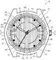
図2は、上記構成の太陽電池10を、電子機器の一例である腕時計に利用した実施形態にかかり、腕時計の平面図である。
この腕時計20の表示部材22は、指針と文字盤とを有するアナログ表示部材である。
【0020】
表示部材22は、時刻を表す時針24、分を表す分針26及び秒を表す秒針28とからなる指針と、表示部材22の周縁に沿って配置された時刻を表示するための文字,模様等からなる目盛り23を有する文字盤とからなる。
この実施形態では、図1の太陽電池10が、表裏を反転させて腕時計20に取り付けられる。すなわち、太陽電池10は、導電部141,142,143,144及び光発電セル18を形成した表面を下に向けた状態で、腕時計20に取り付けられる。また、この実施形態の太陽電池10は、腕時計20の表示部材22よりも大きく形成されている。太陽電池10の導電部141〜144は、外装ケース30の内側に張り出し形成された見切り部30aによって、外側から容易に見ることができないように隠されている。
【0021】
この実施形態の腕時計20は、太陽電池10を構成する透明基板12の裏面に、時刻を表す目盛り23が刻印又は印刷等されている。したがって、この実施形態では、透明基板12の裏面と目盛り23とで、アナログ表示部材の文字盤を形成している。もちろん、目盛り23は透明基板12の裏面に限らず、表面に設けるものとしてもよい。また、目盛り23を光発電セルで形成してもよい。
時針24,分針26及び秒針28を駆動させるムーブメント42は腕時計20の中央に配置され、外装ケース30の内周面から延びる4つのリブ部分19a,19b,19c,19dによって支持されている。リブ部分19a,19b,19c,19dは、それぞれ、時針24が12時、3時、6時及び9時を指す位置に設けられていて、この腕時計20の表示部材22の一部を構成している。
【0022】
なお、ムーブメント42を腕時計20の中央で支持することができるのであれば、リブの数は4本に限らず、1本〜3本又は5本以上としてもよい。
リブ部分19a,19b,19c,19dの間には、腕時計20の径方向に拡がり、かつ、垂直方向に貫通する4つの空間部32が形成されている。そして、この腕時計20では、裏蓋としてガラス板等の透明な基板を用いることで、空間部32を通して、腕時計20を上側から下側まで(あるいは下側から上側まで)見通すことが可能になる。
【0023】
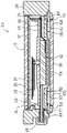
この腕時計20の詳細を、図3及び図4〜図6を参照しながら説明する。
図3は、この腕時計の図2におけるI−I方向断面図、図4〜図6は、この腕時計の分解斜視図である。
図3及び図4に示すように、外装ケース30の上側には、風防ガラス34,パッキン35、太陽電池10及び太陽電池保持部材36が取り付けられる。
【0024】
外装ケース30の下側には、図3,図5及び図6に示すように、裏蓋としての風防ガラス56,押さえ部材58,ムーブメント保持部材50,中枠44,ムーブメント支持部材40及び見切りリング38が取り付けられる。
以下、外装ケース30の上側に取り付けられる部材から順に詳しく説明する。
透明基板12の裏面(図3において上側の面)には、この腕時計20の文字盤を構成する時刻表示用の目盛り23が印刷、刻印又は貼り付け等により、予め形成されている。太陽電池10は、リング状の太陽電池保持部材36に保持されて、外装ケース30に上側から嵌め込まれる。太陽電池保持部材36の内周面には、太陽電池10の周縁と係合して太陽電池10を受ける、段付き状の受け部36aが形成されている。そして、太陽電池保持部材36の上方から太陽電池10を太陽電池保持部材36に嵌め込むと、太陽電池10の周縁が受け部36aに係合して、太陽電池保持部材36に保持される。
【0025】
太陽電池10の円周の一部には、回り止めのための切欠17が形成されていて、この切欠17に係合する切欠係合部36bが、太陽電池保持部材36に形成されている。切欠17が切欠係合部36bに係合するように太陽電池10を太陽電池保持部材36に嵌め込むことで、太陽電池保持部材36に対する太陽電池10の回転を防止することができる。
【0026】
太陽電池保持部材36の切欠係合部36bを形成した部位には、受け部36aから太陽電池保持部材36の他側に貫通する溝37が形成されている。この溝37には、太陽電池10の電力をムーブメント42等に供給するための接続部材60が配置される。この接続部材60の一側には、太陽電池10を太陽電池保持部材36とともに外装ケース30の内部に組み込んだときに、太陽電池10の導電部141,144に形成された出力端子16a,16b(図1参照)に押しつけられる第1の接触部としての二つの接触子61,62を有している。この接触子61,62は、、出力端子16a,16bとの接触状態を確実に確保して太陽電池10からムーブメント42への電力の供給を保証するように、板ばね状に形成されている。
【0027】
接続部材60の他側には、接触子61と導通する接触子63及び接触子62と導通する接触子64が設けられている。この接触子63,64は、導電パターン46の一部に形成された図示しない正側の入力端子と負側の入力端子に押しつけられた状態で確実に接触するように、板ばね状に形成されている。このように、各接触子61〜64を板ばね状に形成することで、太陽電池10と導電パターン46とを確実に接続状態にすることができるばかりでなく、腕時計20が大きな衝撃を受けても、この接続状態を維持することができる。
上記した溝37及び接続部材60は、太陽電池保持部材36の内側に嵌め込まれる後述の見切りリング38によって、外部からは見えないように隠される。
【0028】
外装ケース30の内面には、鍔状の受け部30aが形成されていて、太陽電池10を保持した太陽電池保持部材36を上方から外装ケース30に嵌め込むと、この受け部30aによって太陽電池保持部材36が外装ケース30内で支持される。そして、太陽電池10の上にパッキン35を載せ、パッキン35を介して外装ケース30に風防ガラス34を嵌め込んで固定する。もちろん、風防ガラス34は、接着材等で外装ケース30に固定してもよい。これで、腕時計20の上側部分が完成する。
【0029】
次に、外装ケース30の下側に取り付けられる部材について説明する。
見切りリング38は、太陽電池保持部材36の内側に嵌め込まれて太陽電池保持部材36の内周面を隠す見切り部38aと、外装ケース30の内周面とほぼ同じ外径を有する鍔部38bとを有する。下側から見切りリング38を外装ケース30の内部に挿入すると、鍔部38bの外周面が外装ケース30の内周面に当接して、見切りリング38が腕時計20の内部で位置決めされる。
ムーブメント42を支持するリング状のムーブメント支持部材40は、見切りリング38の下に配置される。ムーブメント支持部材40は、外装ケース30の内径よりも若干小さい外径を有する外リング部40bと、ムーブメント42を支持する円盤状の支持部40aとを有している。支持部40aの表面は、通常の腕時計の文字盤と同様に表面仕上げがなされている。支持部40aの径は、腕時計20の少なくとも分針26の長さよりも小さいものであることが好ましい。また、時針24の長さよりも小さいものであることがより好ましい。
【0030】
支持部40aと外リング部40bとは、この腕時計20の12時,3時,6時及び9時の位置に形成された四つのリブ41によって連結されている。リブ41の断面形状は下向きコの字状に形成され、この下向きコの字状の部分が、通路41aを形成している。
【0031】
なお、支持部40aと外リング部40bとをしっかりと連結することができるのであれば、リブ41の個数は四つに限らず一つ〜三つ又は五つ以上であってもよい。また、リブ41を設ける位置も上記の位置に限られず、腕時計20のデザイン等を考慮して任意適当な位置を選択することができる。
【0032】
ムーブメント支持部材40に下側から取り付けられる中枠44は、ムーブメント42が嵌め込まれるムーブメント嵌入部44cを有する内リング部44aと、この内リング部44aの周囲に形成された外リング部44bと、内リング部44aと外リング部44bとを連結するリブ45とを有している。内リング部44aの外形は、ムーブメント支持部材40の支持部40aの下面に取り付けられたムーブメント42とリブ41の端部との間の隙間41bに嵌まり込むように形成される。
また、外リング部44bは、外装ケース30の内周面に内接し、かつ、ムーブメント支持部材40の外リング部40bに外接する大きさに形成されている。さらに、リブ45は、ムーブメント支持部材40のリブ41の通路41a内に嵌め込まれるように形成される。中枠44の四つのリブ45のうち、腕時計20の3時の位置に位置するリブ45には、リューズ48の巻真49が挿通できる下向きコの字状の通路45aが形成されている。
【0033】
ムーブメント保持部材50は、ムーブメント支持部材40の外リング部40bと同じ外形を有する外リング部50bと、中枠44の内リング部44aが嵌め込まれる孔50cを有し、かつ、ムーブメント支持部材40の支持部40aの外径と同じ外径を有するリング状の内リング部50aとを有している。内リング部50aと外リング部50bとは、ムーブメント支持部材40のリブ41と同じ位置に設けられた四つのリブ51によって連結されている。リブ51の断面形状は上向きコの字状に形成され、この上向きコの字状の部分に、中枠44のリブ45が嵌め込まれる通路51aが形成されている。
【0034】
上記のように形成されたムーブメント支持部材40とムーブメント保持部材50とは、中枠44を真ん中に嵌め込んだ状態で重ね合わされる。すなわち、中枠44のリブ45を、ムーブメント支持部材40の通路41a及びムーブメント保持部材50の通路51aに位置合わせした状態で、ムーブメント支持部材40の隙間41b(図5参照)とムーブメント保持部材50の内リング部50aの孔50cに、中枠44の内リング部44aを嵌め込む。これにより、ムーブメント支持部材40の外リング部40b及びムーブメント保持部材50の外リング部50bが、中枠44の外リング部44bの内側に嵌め込まれる。
そして、ムーブメント支持部材40のリブ41、中枠44のリブ45及びムーブメント保持部材50のリブ51が、腕時計20のリブ部分19a〜19dを形成する。また、腕時計20の3時の位置に位置するムーブメント支持部材40の通路41a及びムーブメント保持部材50の通路51aが、リブ部分19bの内部通路43b(図3参照)を形成し、9時の位置に位置する通路41a及び通路51aがリブ部分19dの内部通路43dを形成する。
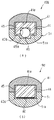
【0035】
図7は、ムーブメント支持部材40、中枠44及びムーブメント保持部材50を組み付けた状態におけるリブ部分19b,19cの断面図で、図7(a)は図2のII-II断面図、図7(b)は図2のIII-III断面図である。
図7(a)及び図7(b)に示すように、中枠44のリブ45が、ムーブメント支持部材40のリブ41の通路41a及びムーブメント保持部材50のリブ51の通路51aの双方に嵌まり込むことで、ムーブメント支持部材40及びムーブメント保持部材50が相対的に回転しないようになっている。
【0036】
また、腕時計20の3時の位置に位置するリブ部分19bの内部通路43bを通して巻真49が設けられ、腕時計20の9時の位置に設けられたリブ部分19dの内部通路43dに、太陽電池10の電力をムーブメント42に供給するためのシート状の導電パターン46が設けられる。この実施形態では、この導電パターン46が導電部材を形成する。導電パターン46は、リブ部分19dを構成する中枠44のリブ45の上に貼り付けられている。
なお、巻真49と導電パターン46とは、図7(a)(b)に示すように別々のリブ部分19b,19dに設けるものとしてもよいが、同一のリブ部分、例えば、巻真49が挿通するリブ部分19bに設けるものとしてもよい。
【0037】
この実施形態では、上記のように組み立てられたムーブメント支持部材40,中枠44及びムーブメント保持部材50が内ケースを構成する。そして、この内ケースを、下方側から外装ケース30の中に嵌め込む。この後、外装ケース30の下側から、Oリング57を介して、ねじ部58aを有するリング状の押さえ部材58を外装ケース30に螺入する。
【0038】
これにより、ムーブメント支持部材40、ムーブメント42、中枠44及びムーブメント保持部材50が外装ケース30内で固定される。また、このとき、導電パターン46の図示しない正側の入力端子と負側の入力端子に、既に外装ケース30の上側に組み込まれている太陽電池保持部材36の接続部材60の接触子63,64が接触し、太陽電池10からムーブメント42に電力を供給可能な状態になる。
なお、ムーブメント42の裏面には、所定の事項を記入した銘盤54を貼り付けておく。
【0039】
リング状の押さえ部材58の開口には、パッキン59を介して裏面側の風防ガラス56が嵌め込まれ、固定される。この実施形態の腕時計20は、Oリング57,パッキン35及びパッキン59によって、防水性が保たれる。
なお、風防ガラス56は、パッキン59以外にも、接着材等によって外装ケース30に固定してもよい。
このようにして、完成した腕時計は、3時、6時、9時及び12時の位置に設けられたリブ部分19a〜19dの間に、腕時計20の径方向に拡がり、かつ、垂直方向に貫通する空間部32が形成される。さらに、腕時計20の裏蓋にも透明な風防ガラス56が用いられていることから、上側から下側までを見通すことのできる斬新なデザインを得ることができる。
【0040】
なお、太陽電池10を腕時計20の表側に設ける代わりに、裏蓋側(風防ガラス56側)に設けるものとしてもよい。また、裏蓋側(風防ガラス56側)に、太陽電池10と同様の太陽電池を付加的に設けてもよい。
裏蓋側にも空間部32を透過した光が達するので、裏蓋側に設けた前記太陽電池によっても起電力が得られる。
特に、表側と裏蓋側の両方に太陽電池を設ければ、表側の太陽電池10の起電力を小さくしても、その分を裏蓋側の太陽電池の起電力で補うことができるようになるので、太陽電池10の光発電セル18の線幅をさらに小さく、あるいは間隔sをさらに広くして、太陽電池10の透明度を高めることができる。
【0041】
この実施形態の腕時計20は、図2及び図5に示すように、ムーブメント支持部材40の支持部40aの径が、腕時計20の時針24,分針26及び秒針28の長さよりも小さいので、これら指針24,26,28の先端が支持部40aから突出して腕時計20の裏側から見え、かつ、目盛り23が太陽電池10の透明基板12に設けられているので、腕時計20の裏側からも時刻を知ることができるという面白さがある。
【0042】
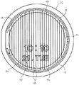
本発明は、上記したアナログ時計に限らずディジタル時計にも適用が可能である。
図8に、本発明をディジタル時計に適用した実施形態の平面図を示す。ディジタル表示部材72は、腕時計70の表示板71の上に設けても良いが、太陽電池10の下面(裏面)に設けてもよい。
また、太陽電池10を構成する透明基板12に直接ディジタル表示部材72を形成するようにしてもよい。この場合、透明基板12として偏光板を使用することで、ディジタル表示部材72の偏光板を省略することが可能になる。
【0043】
本発明の好適な実施形態を説明してきたが、本発明は、上記の実施形態により限定されるものではない。
例えば、電子機器として腕時計を例に挙げて説明したが、本発明は置き時計や掛け時計等の他の時計にも適用が可能であり、さらに、時計以外の他の電子機器にも適用が可能である。
【0044】
また、アナログ時計及びディジタル時計についてのみ説明したが、アナログ・ディジタルコンビネーション時計にも本発明を適用することが可能である。
また、上記の実施形態では、腕時計20の風防ガラス34の下に、透明基板12を基材とする太陽電池10を設けるものとして説明したが、風防ガラス34に直接細線状の光発電セル18を形成することで、腕時計20の厚みを薄くすることができる。
【0045】
【発明の効果】
本発明によれば、光発電セルをきわめて細くし、かつ、この光発電セルを表示部材のほぼ全面を横切るように設けることで太陽電池の透明性を向上させることができる。そして、このような透光形太陽電池を用いることで、電子機器、特に時計のデザイン選択の自由度を大幅に向上させることができる。
また、時計の径方向に拡がり、かつ、垂直方向に貫通する空間を形成するとともに、時計の裏蓋にも透明なガラスを用いることで、上側から下側までを見通すことのできる斬新なデザインの時計を得ることができ、利用者の遊び心を満足させることができるようになる。
【図面の簡単な説明】
【図1】 本発明の電子機器に使用される透光形太陽電池の平面図である。
【図2】 図1の太陽電池を、電子機器の一例である腕時計に利用した実施形態にかかり、腕時計の平面図である。
【図3】 図2のI−I方向断面図である。
【図4】 図2の腕時計の分解斜視図で、外装ケースの上側に組み込まれる部材の斜視図である。
【図5】 図2の腕時計の分解斜視図で、外装ケースの下側に組み込まれる見切りリングとムーブメント支持部材の斜視図である。
【図6】 図2の腕時計の分解斜視図で、外装ケースの下側に組み込まれるその他の部材の斜視図である。
【図7】 ムーブメント支持部材、中枠及びムーブメント保持部材を組み付けた状態におけるリブ部分の断面図で、図7(a)は図2のII-II断面図、図7(b)は図2のIII-III断面図である。
【図8】 本発明の他の実施形態を説明する平面図である。
【符号の説明】
10 太陽電池(透光形太陽電池)
12 透明基板
141〜144 導電部
15 接続部
16a,16b 出力端子
17 切欠係合部
18 光発電セル
19a〜19d リブ部分
20 腕時計
22 表示部材
23 目盛り
24 時針
26 分針
28 秒針
30 外装ケース
30a 見切り部
32 空間部
34,56 風防ガラス
36 太陽電池保持部材
36a 受け部
38 見切りリング
38a 見切り部
38b 鍔部
40 ムーブメント支持部材
42 ムーブメント
43b、43d 内部通路
44 中枠
46 導電パターン(導電部材)
50 ムーブメント保持部材
60 接続部材
61,62 接触子(第1の接触部)
63,64 接触子(第2の接触部)
70 腕時計(他の実施形態)
71 表示板
72 ディジタル表示部材[0001]
BACKGROUND OF THE INVENTION
The present invention relates to an electronic apparatus having a solar cell and having a device driven by the power generated by the solar cell, and in particular, by using a transparent solar cell having a thin-line photovoltaic cell. The present invention relates to electronic devices that can be diversified.
[0002]
[Prior art]
2. Description of the Related Art An electronic device that includes a solar cell and incorporates a device that operates using the solar cell as a power source is well known.
By the way, since the photovoltaic cell which receives light and generates electric power is usually made of an opaque material such as dark brown, the solar cell is provided on a digital display member or an analog display member. I couldn't.
For this reason, when a solar cell is to be mounted on an electronic device equipped with a digital display member or an analog display member, the display device must be mounted avoiding the display member. Will receive.
[0003]
In order to solve such a problem, a solar cell made transparent by forming thin line photovoltaic cells on a transparent substrate at regular intervals is disclosed in, for example, Japanese Utility Model Publication No. 57-94964. Known in publications.
The solar cell described in this publication is obtained by etching a photovoltaic cell on a transparent substrate so as to be sufficiently thin, so that the solar cell looks transparent within the human visual range.
However, since the electronic device described in this publication forms a solar cell by forming a single photovoltaic cell in a single stroke on a transparent substrate, sufficient electric power necessary for the operation of the electronic device is obtained. It cannot be substantially obtained from the solar cell and has not yet been realized.
[0004]
In recent years, skeletons with a transparent interior have become popular, and watches with higher transparency are demanded from playfulness.
However, in the conventional timepiece using a solar cell, for the reason of the nature of the solar cell being opaque and the functional reason that a sufficient electromotive force cannot be obtained if the effective area of the solar cell is reduced, the above-mentioned It was difficult to meet such demands.
[0005]
[Problems to be solved by the invention]
The present invention has been made in view of the above problems, and a solar cell that can improve transparency by making the photovoltaic cell extremely thin and can obtain an electromotive force sufficient to operate an electronic device. An object of the present invention is to provide an electronic device that can greatly improve the degree of freedom of design selection of the electronic device and satisfy the playfulness of the user.
[0006]
[Means for Solving the Problems]
In order to solve the above problems, the present invention provides an electronic apparatus including a solar cell, a device driven by the power generated by the solar cell, and a display member that is driven by the device and displays predetermined contents. In the solar cell, a transparent substrate and a transparent substrateProvided along the peripheryA plurality of conductive parts connected in series by a connection part and a plurality of conductive parts formed at appropriate intervals on the transparent substrateInA thin-line photovoltaic cell connected to the conductive portion;,And the display member is the conductive portion.ofConfiguration placed insideWhenIt is.
According to this configuration, by forming a plurality of thin-line photovoltaic cells on the transparent substrate at appropriate intervals, it is difficult to visually recognize the photovoltaic cells, and a transparent solar cell can be obtained.
The intervals between the photovoltaic cells are preferably equal. By doing in this way, a more transparent solar cell can be obtained.
Further, by connecting a plurality of conductive portions in series and connecting the photovoltaic cell to the conductive portions, it is possible to obtain a sufficient electromotive force necessary for the operation of the electronic device.
[0007]
The thin-line photovoltaic cell is formed by extending from each of the conductive portions in a direction crossing the transparent substrate, and extending to the vicinity of the conductive portion, so that a portion where the photovoltaic cell is not formed is extremely close to the periphery of the transparent substrate. It can be limited to a small region, and color unevenness of the translucent solar cell can be alleviated.
By using a translucent solar cell as described above, the solar cell can be disposed above the display member of the electronic device, and the degree of freedom in design selection can be increased.
[0008]
The display member may be a liquid crystal display, and the liquid crystal display may be provided on the back surface of the transparent substrate. Moreover, you may form integrally with a translucent solar cell.
Further, the translucent solar cell is disposed above the case of the electronic device, the device is disposed below the translucent solar cell in the case, and a space is provided between the device and the case. And a transparent member may be disposed on the lower surface side of the electronic device so that the electronic device can be seen from the upper side to the lower side.
In this case, the translucent solar cell may be arranged on the lower side of the case. Moreover, you may arrange | position a translucent solar cell only to the lower side of the said case.
[0009]
By using the present invention for a timepiece, the degree of freedom in design selection in the timepiece can be improved.
The timepiece may be an analog timepiece or a digital timepiece.
By using the translucent solar cell, the solar cell can be provided above the hands of the analog timepiece.
[0010]
Further, the dial of the analog timepiece dial may be provided on the front or back surface of the transparent substrate.
Also in this timepiece, the translucent solar cell is arranged on the front side of the case of the timepiece, the pointer of the analog display member is located below the translucent solar cell in the case, and a movement for driving the pointer And a space is formed between the movement and the case, and a transparent plate is arranged on the lower surface side of the timepiece so that the timepiece can be seen from the upper side to the lower side. .
In this case, the transparent substrate can be sized to cover the movement and the space.
[0011]
Moreover, you may arrange | position the said translucent solar cell not only on the front side of the said case but the back cover side. The translucent solar cell may be arranged only on the case back side of the case.
Furthermore, the case and the movement may be connected by one or a plurality of ribs so that the movement is supported on the center side of the case.
In this case, a conductive member for supplying electric power from the translucent solar cell to the movement through the inside of the rib may be disposed.
In particular, the conductive portion of the transparent substrate and the conductive member are connected by a connecting member, and the connecting member is biased to the first contact portion biased to the output terminal of the conductive portion and the conductive member. It is good to comprise so that it may have the 2nd contact part made.
By using such a connection member, the assembly of the solar cell is facilitated, and the solar cell and the conductive member can be reliably connected.
Moreover, it is good for the minute hand which displays at least a minute among the said pointers of the said analog display member to extend above the said space between the said case and the said movement. This makes it possible to know the time from the back side of the watch.
[0012]
DETAILED DESCRIPTION OF THE INVENTION
Preferred embodiments of the present invention will be described in detail with reference to the drawings.
FIG. 1 is a plan view of a translucent solar cell used in the electronic apparatus of the present invention.
The translucent solar cell 10 (hereinafter referred to as the solar cell 10) is formed using a
[0013]
On the surface of the
[0014]
The
[0015]
Further, adjacent
[0016]
The
[0017]
One end of the
In this way, by providing a plurality of conductive portions connected to the
[0018]
The other end of the
[0019]
FIG. 2 is a plan view of a wristwatch according to an embodiment in which the
The
[0020]
The
In this embodiment, the
[0021]
In the
A
[0022]
As long as the
Between the
[0023]
Details of the
FIG. 3 is a cross-sectional view taken along the line II in FIG. 2, and FIGS. 4 to 6 are exploded perspective views of the wristwatch.
As shown in FIGS. 3 and 4, the
[0024]
As shown in FIGS. 3, 5, and 6, a
Hereinafter, the components attached to the upper side of the
On the back surface (upper surface in FIG. 3) of the
[0025]
A
[0026]
A
[0027]
On the other side of the connecting
The
[0028]
A hook-shaped receiving portion 30a is formed on the inner surface of the
[0029]
Next, the member attached to the lower side of the
The
A ring-shaped
[0030]
The
[0031]
Note that the number of the
[0032]
The
Further, the
[0033]
The
[0034]
The
The
[0035]
7 is a cross-sectional view of the
As shown in FIGS. 7A and 7B, the
[0036]
Further, a winding
The winding
[0037]
In this embodiment, the
[0038]
Thereby, the
A
[0039]
The
The
In this way, the completed wristwatch extends in the radial direction of the
[0040]
Instead of providing the
Since the light transmitted through the
In particular, if solar cells are provided on both the front side and the back cover side, even if the electromotive force of the
[0041]
As shown in FIGS. 2 and 5, the
[0042]
The present invention can be applied not only to the analog timepiece described above but also to a digital timepiece.
FIG. 8 shows a plan view of an embodiment in which the present invention is applied to a digital timepiece. The
Further, the
[0043]
Although preferred embodiments of the present invention have been described, the present invention is not limited to the above-described embodiments.
For example, although a wristwatch has been described as an example of an electronic device, the present invention can be applied to other clocks such as a table clock and a wall clock, and can also be applied to other electronic devices other than a clock. .
[0044]
Further, only the analog timepiece and the digital timepiece have been described, but the present invention can also be applied to an analog / digital combination timepiece.
In the above-described embodiment, the
[0045]
【The invention's effect】
According to the present invention, it is possible to improve the transparency of the solar cell by making the photovoltaic cell extremely thin and providing the photovoltaic cell so as to cross almost the entire surface of the display member. And the freedom degree of the design selection of an electronic device, especially a timepiece can be improved significantly by using such a translucent solar cell.
In addition to forming a space that extends in the radial direction of the watch and penetrates in the vertical direction, it uses a transparent glass for the back cover of the watch. A clock can be obtained and the playfulness of the user can be satisfied.
[Brief description of the drawings]
FIG. 1 is a plan view of a translucent solar cell used in an electronic apparatus of the present invention.
FIG. 2 is a plan view of a wristwatch according to an embodiment in which the solar cell of FIG. 1 is used in a wristwatch that is an example of an electronic device.
3 is a cross-sectional view taken along the line II in FIG.
4 is an exploded perspective view of the wristwatch of FIG. 2, and is a perspective view of members incorporated on the upper side of the exterior case. FIG.
5 is an exploded perspective view of the wristwatch of FIG. 2, and is a perspective view of a parting ring and a movement support member incorporated under the outer case. FIG.
6 is an exploded perspective view of the wristwatch of FIG. 2, and is a perspective view of other members incorporated under the exterior case. FIG.
7 is a cross-sectional view of the rib portion in a state where the movement support member, the middle frame, and the movement holding member are assembled, FIG. 7 (a) is a cross-sectional view taken along the line II-II of FIG. 2, and FIG. It is III-III sectional drawing.
FIG. 8 is a plan view for explaining another embodiment of the present invention.
[Explanation of symbols]
10 Solar cell (translucent solar cell)
12 Transparent substrate
141~ 144 Conductive part
15 connections
16a, 16b output terminal
17 Notch engaging part
18 Photovoltaic cell
19a-19d Rib part
20 watches
22 indicationsElement
23 scales
24 hour hand
26 minute hand
28 second hand
30 exterior case
30a parting part
32 Space
34,56 Windshield
36 Solar cell holding member
36a receiving part
38 parting ring
38a parting part
38b
40 Movement support member
42 Movement
43b, 43d Internal passage
44 Middle frame
46 Conductive pattern (conductive member)
50 Movement holding member
60 connecting members
61, 62 Contact (first contact portion)
63, 64 contact (second contact part)
70 Watch (Other Embodiments)
71 Display board
72 Digital display members
Claims (22)
前記太陽電池は、透明基板と、この透明基板の周縁に沿って設けられ接続部により直列に接続された複数の導電部と、前記透明基板上に適宜の間隔で複数形成されるとともに前記導電部に接続された細線状の光発電セルと、を有する透光形太陽電池であり、
前記表示部材は、前記導電部の内側に配置されることを特徴とする電子機器。In an electronic device including a solar cell, a device driven by the power generated by the solar cell, and a display member that is driven by the device to display predetermined contents,
The solar cell includes a transparent substrate, wherein the connection portion is provided along the periphery of the transparent substrate and a plurality of conductive portions connected in series, in together when a plurality of formed at appropriate intervals on the transparent substrate A thin-line photovoltaic cell connected to the conductive portion , and a translucent solar cell having
Wherein the display member is an electronic device, characterized in that disposed inside the conductive portion.
Priority Applications (4)
| Application Number | Priority Date | Filing Date | Title |
|---|---|---|---|
| JP2000078920A JP4607277B2 (en) | 2000-03-21 | 2000-03-21 | Electronics |
| PCT/JP2001/002091 WO2001071434A1 (en) | 2000-03-21 | 2001-03-16 | Electronic unit |
| US09/959,096 US6521822B2 (en) | 2000-03-21 | 2001-03-16 | Electronic unit |
| EP01912422.1A EP1186966B1 (en) | 2000-03-21 | 2001-03-16 | Electronic unit |
Applications Claiming Priority (1)
| Application Number | Priority Date | Filing Date | Title |
|---|---|---|---|
| JP2000078920A JP4607277B2 (en) | 2000-03-21 | 2000-03-21 | Electronics |
Publications (3)
| Publication Number | Publication Date |
|---|---|
| JP2001264464A JP2001264464A (en) | 2001-09-26 |
| JP2001264464A5 JP2001264464A5 (en) | 2007-04-19 |
| JP4607277B2 true JP4607277B2 (en) | 2011-01-05 |
Family
ID=18596256
Family Applications (1)
| Application Number | Title | Priority Date | Filing Date |
|---|---|---|---|
| JP2000078920A Expired - Fee Related JP4607277B2 (en) | 2000-03-21 | 2000-03-21 | Electronics |
Country Status (1)
| Country | Link |
|---|---|
| JP (1) | JP4607277B2 (en) |
Families Citing this family (5)
| Publication number | Priority date | Publication date | Assignee | Title |
|---|---|---|---|---|
| US7057102B2 (en) | 2000-11-10 | 2006-06-06 | Citizen Watch Co., Ltd. | Solar cell module and portable electronic apparatus with it |
| KR20090121629A (en) * | 2008-05-22 | 2009-11-26 | 삼성전자주식회사 | Solar cell and solar cell module using the same |
| JP5123235B2 (en) * | 2009-03-19 | 2013-01-23 | シチズンホールディングス株式会社 | clock |
| JP6927245B2 (en) | 2019-03-26 | 2021-08-25 | カシオ計算機株式会社 | Solar panels, display devices and clocks |
| JP6891914B2 (en) * | 2019-03-26 | 2021-06-18 | カシオ計算機株式会社 | Solar panels, display devices and clocks |
Citations (3)
| Publication number | Priority date | Publication date | Assignee | Title |
|---|---|---|---|---|
| JP2000162342A (en) * | 1998-11-30 | 2000-06-16 | Sanyo Electric Co Ltd | Clock with solar cell |
| JP2000187204A (en) * | 1998-12-22 | 2000-07-04 | Citizen Watch Co Ltd | Liquid crystal display device |
| JP2000221282A (en) * | 1999-01-29 | 2000-08-11 | Citizen Watch Co Ltd | Time piece |
Family Cites Families (5)
| Publication number | Priority date | Publication date | Assignee | Title |
|---|---|---|---|---|
| JPS5677885A (en) * | 1979-11-28 | 1981-06-26 | Citizen Watch Co Ltd | Liquid crystal display unit |
| JPS5794964U (en) * | 1980-12-02 | 1982-06-11 | ||
| JPS63181989U (en) * | 1987-05-15 | 1988-11-24 | ||
| JPH07287081A (en) * | 1994-04-18 | 1995-10-31 | Citizen Watch Co Ltd | Connection structure for solar cell |
| JPH1048358A (en) * | 1996-08-08 | 1998-02-20 | Casio Comput Co Ltd | Indicator and electronic apparatus |
-
2000
- 2000-03-21 JP JP2000078920A patent/JP4607277B2/en not_active Expired - Fee Related
Patent Citations (3)
| Publication number | Priority date | Publication date | Assignee | Title |
|---|---|---|---|---|
| JP2000162342A (en) * | 1998-11-30 | 2000-06-16 | Sanyo Electric Co Ltd | Clock with solar cell |
| JP2000187204A (en) * | 1998-12-22 | 2000-07-04 | Citizen Watch Co Ltd | Liquid crystal display device |
| JP2000221282A (en) * | 1999-01-29 | 2000-08-11 | Citizen Watch Co Ltd | Time piece |
Also Published As
| Publication number | Publication date |
|---|---|
| JP2001264464A (en) | 2001-09-26 |
Similar Documents
| Publication | Publication Date | Title |
|---|---|---|
| WO2001071434A1 (en) | Electronic unit | |
| US4926401A (en) | Skeleton watch allowing sight of all or some of the elements forming it | |
| US20150029829A1 (en) | Timepiece Comprising An Analog Display and a Digital Display | |
| JPS6151745B2 (en) | ||
| JP4355104B2 (en) | clock | |
| KR200278568Y1 (en) | A fashion watch | |
| US4312056A (en) | Composite display type electronic timepiece | |
| JP4607277B2 (en) | Electronics | |
| JP2007256062A (en) | Electronic component, electronic equipment, and dial | |
| JPH07128458A (en) | Structure of timepiece dial | |
| JP3651190B2 (en) | Display device and clock | |
| ES2249022T3 (en) | WATCH AND TIMER WITH ANALOG AND DIGITAL SOLAPED SCREENS CONTROLLED SEPARATELY. | |
| GB2084764A (en) | Combination analog/digital timepieces | |
| JP4603666B2 (en) | Electronic clock with solar battery | |
| JP2008151627A (en) | Led display timepiece | |
| CN115840348A (en) | Electronic device and timepiece | |
| JPS6242390Y2 (en) | ||
| JP3477814B2 (en) | Light emitting device and electronic equipment having light emitting device | |
| US20230057778A1 (en) | Watch | |
| JPH06281753A (en) | Alarm clock having replaceable decoration member, wall clock or clock, which is mounted on knapsack | |
| JPH1090440A (en) | Electronic watch mounted with solar battery | |
| KR200179487Y1 (en) | Advertisement watch | |
| JPH0755966A (en) | Hand type watch | |
| JPH095452A (en) | Watch with illumination | |
| JPH0720266A (en) | Pointer type watch |
Legal Events
| Date | Code | Title | Description |
|---|---|---|---|
| A521 | Request for written amendment filed |
Free format text: JAPANESE INTERMEDIATE CODE: A523 Effective date: 20070301 |
|
| A621 | Written request for application examination |
Free format text: JAPANESE INTERMEDIATE CODE: A621 Effective date: 20070301 |
|
| A131 | Notification of reasons for refusal |
Free format text: JAPANESE INTERMEDIATE CODE: A131 Effective date: 20100720 |
|
| A521 | Request for written amendment filed |
Free format text: JAPANESE INTERMEDIATE CODE: A523 Effective date: 20100916 |
|
| TRDD | Decision of grant or rejection written | ||
| A01 | Written decision to grant a patent or to grant a registration (utility model) |
Free format text: JAPANESE INTERMEDIATE CODE: A01 Effective date: 20101005 |
|
| A01 | Written decision to grant a patent or to grant a registration (utility model) |
Free format text: JAPANESE INTERMEDIATE CODE: A01 |
|
| A61 | First payment of annual fees (during grant procedure) |
Free format text: JAPANESE INTERMEDIATE CODE: A61 Effective date: 20101007 |
|
| R150 | Certificate of patent or registration of utility model |
Ref document number: 4607277 Country of ref document: JP Free format text: JAPANESE INTERMEDIATE CODE: R150 Free format text: JAPANESE INTERMEDIATE CODE: R150 |
|
| FPAY | Renewal fee payment (event date is renewal date of database) |
Free format text: PAYMENT UNTIL: 20131015 Year of fee payment: 3 |
|
| S533 | Written request for registration of change of name |
Free format text: JAPANESE INTERMEDIATE CODE: R313533 |
|
| R350 | Written notification of registration of transfer |
Free format text: JAPANESE INTERMEDIATE CODE: R350 |
|
| LAPS | Cancellation because of no payment of annual fees |