JP4604165B2 - Automatic coin replenishment device - Google Patents
Automatic coin replenishment device Download PDFInfo
- Publication number
- JP4604165B2 JP4604165B2 JP2004092103A JP2004092103A JP4604165B2 JP 4604165 B2 JP4604165 B2 JP 4604165B2 JP 2004092103 A JP2004092103 A JP 2004092103A JP 2004092103 A JP2004092103 A JP 2004092103A JP 4604165 B2 JP4604165 B2 JP 4604165B2
- Authority
- JP
- Japan
- Prior art keywords
- coin
- coins
- chute
- holding
- hopper
- Prior art date
- Legal status (The legal status is an assumption and is not a legal conclusion. Google has not performed a legal analysis and makes no representation as to the accuracy of the status listed.)
- Expired - Fee Related
Links
Images


Description
本発明は、コインを金種毎に積み重ねて保留するコイン保留装置に自動的にコインを補給するためのコイン自動整列補給装置に関する。
詳しくは、バラ積みしたコインを一枚ずつ自動的にコイン保留装置の所定金種の保留部に所定数のコインを自動的に補給するためのコイン自動整列補給装置に関する。
さらに、コイン自動整列補給装置から供給されるコインをコイン保留装置に確実に積み重ねるための補助カバーに関する。
なお、本明細書で使用する「コイン」は、コイン、ゲーム機のトークン等を包含する。
The present invention relates to a coin automatic alignment and supply device for automatically supplying coins to a coin holding device that stacks and holds coins for each denomination.
More specifically, the present invention relates to a coin automatic alignment and replenishment device for automatically replenishing a predetermined number of coins to a predetermined denomination holding portion of a coin holding device automatically one by one.
Further, the present invention relates to an auxiliary cover for reliably stacking coins supplied from the coin automatic alignment and replenishment device on the coin holding device.
Note that “coin” used in this specification includes coins, tokens of game machines, and the like.
釣り銭を効率的に正確に払い出すため、図14に示すコイン保留装置が使用されている。
すなわち、このコイン保留装置10に金種毎に所定数積み重ねて保留し、釣り銭払出機に装着し、使用する(例えば、国際公開特許公報WO03/015038A2参照)。
このコイン保留装置10は、コインの直径よりも僅かに大きい直径を有し、縦方向に伸び、かつ、側壁の一部が縦方向に開口12した保留部14が複数並列された本体16と、前記縦方向の開口12を閉じ、かつ、保留部14の上部開口18を閉じるよう本体16の案内溝20挿入することにより着脱可能なカバー22を備えている。
In order to pay out the change efficiently and accurately, a coin holding device shown in FIG. 14 is used.
That is, a predetermined number of coin types are stacked and held in the
The
このカバー20の下端24と本体16の底部26との間にコイン一枚分の隙間があり、また、本体16の背面に形成した開口(図示せず)に突き出し部材が出入りし、最も下のコインが一枚ずつ突き出されるようになっている。
したがって、所定金種の突き出し数を指示することにより、所定金種のコインが所定数払い出される。
この保留部14へのコインの補給は、同一金種を所定数棒状にシートで包んだコイン塊を該当する金種の保留部に上部開口18から挿入する。
その後、包装したシートを除去することにより、所定数のコインを補給している。
この補給作業は、手作業であり、作業効率が低かった。
There is a gap for one coin between the
Therefore, by instructing the number of protrusions of the predetermined denomination, a predetermined number of coins of the predetermined denomination are paid out.
In order to supply coins to the
Thereafter, a predetermined number of coins are replenished by removing the wrapped sheet.
This replenishment work was a manual work, and the work efficiency was low.
この補給作業を効率化するため、金種が混在したコインをトレイに投入し、その投入されたコインを回転ディスクによって一個ずつ区分けし、区分けしたコインを対応する円筒状の保留部に保留することが考えられる(例えば、特許文献1及び特許文献2参照。)。
In order to make this replenishment work more efficient, coins with mixed denominations are thrown into the tray, the inserted coins are sorted one by one by a rotating disk, and the sorted coins are held in the corresponding cylindrical holding parts. (For example, see
前記従来技術は、各種金種が混在して投入されるため、その区分け用の装置が必要であり、小型化することが出来なかった。
また、金種が混在しているため、金種判別を電気的または機械的に一個ずつ行うため、その補給はシリーズで行われ、所定数のコインを速やかに整列することが出来ない問題がある。
In the prior art, since various denominations are input in a mixed manner, an apparatus for sorting them is necessary, and it has not been possible to reduce the size.
In addition, since the denominations are mixed, the denomination is determined one by one electrically or mechanically, so that the replenishment is performed in series, and a predetermined number of coins cannot be quickly arranged. .
本発明の第1の目的は、所定の保留部に、所定金種のコインを所定数、スピーディに積み上げて保留できるコイン自動整列補給装置を提供することである。
本発明の第2の目的は、コイン自動整列補給装置を小型化することである。
本発明の第3の目的は、コイン自動整列補給装置を用いて自動的にコインを保留部に整列補給するに際し、保留部にスムースに保留できるコイン保留装置の補助カバーを提供することである。
A first object of the present invention is to provide an automatic coin alignment and replenishment device capable of quickly storing a predetermined number of coins of a predetermined denomination in a predetermined holding unit.
The second object of the present invention is to reduce the size of the coin automatic alignment and supply device.
A third object of the present invention is to provide an auxiliary cover of a coin holding device that can smoothly hold coins in the holding portion when automatically aligning and supplying coins to the holding portion using the coin automatic alignment and supply device.
これらの目的を達成するため、本発明のコイン自動整列補給装置は以下のように構成される。
筒状のコイン保留部を複数並列したコイン保留装置にコインを自動的に補給するコイン自動整列補給装置において、コインをバラ積み状態で保留する金種毎のコインホッパ、前記コインホッパの下方に位置し、上部が前記コインホッパの所定の出口に接続され、かつ、下部が前記コイン保留装置の所定の保留部に接続されたシュート部、前記コインホッパと前記シュート部を内蔵する箱形のカバー、前記カバーに取り付けられた選択取付装置によって前記シュート部の下方に位置する補給位置と前記シュート部に並列した待機位置に選択的に位置可能である保持部、前記各コインホッパのコイン払出数を制御する制御部、とを備えるコイン自動整列補給装置である。
In order to achieve these objects, the coin automatic alignment and supply device of the present invention is configured as follows.
In a coin automatic alignment and replenishment device that automatically replenishes coins to a coin retaining device in which a plurality of cylindrical coin retaining portions are arranged in parallel, a coin hopper for each denomination that retains coins in a stacked state, located below the coin hopper, upper is connected to a predetermined outlet of said coin hopper and mounting chute portion that is connected to a predetermined holding portion of the lower part the coin reservoir, box-shaped cover which incorporates the chute portion and the coin hopper, the cover A replenishment position positioned below the chute portion by the selected attachment device, a holding portion that can be selectively positioned at a standby position parallel to the chute portion, a control portion that controls the number of coins to be paid out by each coin hopper, and It is an automatic coin alignment supply device provided with.
この構成において、コインホッパは、保留しているコインを一個ずつシュートの上部に払い出す。
シュートの上部に落下したコインは、シュート上を滑り下り、シュート下部からコイン保留装置の相対する保留部に上部開口から落下する。
落下したコインは、保留部の底に支えられ、ほぼ水平に保留される。
所定の時間間隔でコインホッパから払い出されるコインは、前述のようにシュートにガイドされて保留部に落下し、順次積み重なる。
In this configuration, the coin hopper pays out one coin at a time to the upper part of the chute.
The coin that has fallen on the upper part of the chute slides down on the chute and falls from the lower part of the chute to the opposite holding part of the coin holding device from the upper opening.
The dropped coin is supported by the bottom of the holding unit and held almost horizontally.
Coins that are paid out from the coin hopper at a predetermined time interval are guided by the chute as described above, fall to the holding portion, and are sequentially stacked.
コインホッパは所定数のコインを払い出した場合、制御部によって停止される。
これにより、保留部に所定数のコインが積みあがって保留される。
したがって、保留装置の所定の保留部に所定金種のコインが所定数自動的に補給されるので、補給のための時間及び手間が大幅に削減される効果がある。
さらに、シュート部の下方の所定位置にコイン保留装置を保持する保持部が選択的に配置されるので、コインホッパ及びシュート部を内蔵するカバーのサイズは可及的に小型にできる。
When the coin hopper pays out a predetermined number of coins, the coin hopper is stopped by the control unit.
As a result, a predetermined number of coins are stacked and held in the holding unit.
Therefore, since a predetermined number of coins of a predetermined denomination are automatically supplied to a predetermined holding part of the holding device, there is an effect that time and labor for supply are greatly reduced.
Furthermore, since the holding part for holding the coin holding device is selectively disposed at a predetermined position below the chute part, the size of the cover containing the coin hopper and the chute part can be made as small as possible.
さらに、コイン保留装置を装着する保持部が前記カバーに対し選択取付装置によって補給位置と待機位置に移動可能であり、カバーに一体化されているので、紛失の恐れがなく、さらに、コインをコイン保留装置に補給しない場合、シュート部に並列する待機位置に保持できるので、装置を小型にすることができる。 Furthermore , since the holding unit for mounting the coin holding device can be moved to the replenishment position and the standby position by the selective mounting device with respect to the cover and is integrated with the cover, there is no risk of losing, and the coin is inserted into the coin. When the reserving device is not replenished, it can be held at the standby position in parallel with the chute, so that the device can be made compact.
請求項2の発明は、前記コインホッパは、傾斜ベースと回転ディスクを含み、コインの払出口が前記傾斜ベースの上位側にあり、前記払出口に続いて上下方向に延びるガイド通路が前記傾斜ベースと並列に配置され、前記ガイド通路の下端部は、前記シュート部の上方に位置する請求項1のコイン自動整列補給装置である。
この構成において、コインは回転ディスクによって傾斜ベースの上位側にある払出口から払い出される。
これにより、払出口の下方にほぼ垂直に伸びるガイド通路を傾斜ベースに並置することができる。
この構成により、ガイド通路においてコインの姿勢をほぼ一定にすることができるので、シュート部でのコイン姿勢を毎回均一にすることができる。
これにより、シュート部におけるコイン姿勢が毎回同一になるので、コインの滑り落ち速度がほぼ均一になり、コイン保留装置にコインを水平に積み上げることができる。
さらに、ガイド通路が垂直であるため、装置を小型化できる利点がある。
The invention of
In this configuration, coins are paid out from the payout opening on the upper side of the tilt base by the rotating disk.
As a result, the guide passage extending substantially vertically below the payout opening can be juxtaposed on the inclined base.
With this configuration, since the posture of the coin can be made substantially constant in the guide passage, the coin posture at the chute can be made uniform every time.
Thereby, since the coin attitude | position in a chute | shoot part becomes the same each time, the sliding-down speed | velocity | rate of a coin becomes substantially uniform, and a coin can be piled up horizontally on a coin holding device.
Further, since the guide passage is vertical, there is an advantage that the apparatus can be miniaturized.
請求項3の発明は、前記ガイド通路の前記払出口に相対した位置に、緩衝体を揺動可能に垂下した請求項2のコイン自動整列補給装置である。
この構成において、払出口から投出されたコインは緩衝体に衝突してそれを移動させることにより運動エネルギーを減衰されるため、ほぼ下方に落下する。
この落下時、コインはガイド通路の壁面に案内されてほぼ垂立状態になるため、落下姿勢は毎回ほぼ一定になる。
したがって、シュート部に移動する際、コインの姿勢は毎回同一であるので、シュート部でのコイン姿勢が安定し、結果としてコインの整列がスピーディに行われる利点がある。
The invention according to claim 3 is the coin automatic alignment and replenishment device according to
In this configuration, the coins thrown out from the payout opening collide with the buffer body and move it so that the kinetic energy is attenuated.
At the time of the fall, the coin is guided to the wall surface of the guide passage so as to be in a substantially vertical state, so that the fall posture is almost constant every time.
Therefore, since the coin posture is the same every time when moving to the chute portion, the coin posture at the chute portion is stabilized, and as a result, there is an advantage that the coins are quickly aligned.
本発明は、筒状のコイン保留部を複数並列したコイン保留装置、前記コイン保留装置の下端部開口を閉止し、かつ、前記コイン保留装置の上端部上方に位置して前記シュート部の下部の側方に位置するカバーを含み、前記カバーが前記コイン保留装置に着脱可能であるコイン補給装置用のコイン自動整列補給装置の補助カバーを含むことが好ましい。
この構成において、前記補助カバーがコイン保留装置に装着された後、そのコイン保留装置をコイン整列補給装置の保持部に装着するので、コインホッパから払い出され、シュートを滑り落ちたコインは、まずカバーの上部に衝突して案内された後、保留部に落下する。
保留部の下端部開口はカバーの下部によって閉止されているため、保留部に落下したコインは、下端部開口から飛び出すことがない。
したがって、コインホッパから払い出されたコインは、カバーのサポートを受けてコイン保留部に水平状態に積み重なって保留される利点を有する。
The present invention provides a coin holding device in which a plurality of cylindrical coin holding portions are arranged side by side, closes a lower end opening of the coin holding device, and is located above the upper end portion of the coin holding device and below the chute portion. includes a cover positioned on the side, it is preferable to include an auxiliary cover of the coin automatic alignment replenishing apparatus for a coin replenishing apparatus wherein the cover is detachable to the coin reservoir.
In this configuration, after the auxiliary cover is attached to the coin holding device, the coin holding device is attached to the holding portion of the coin alignment supply device, so that the coins that are paid out from the coin hopper and slide down the chute are first covered. After colliding with the upper part of the guide, it falls to the holding part.
Since the lower end opening of the holding part is closed by the lower part of the cover, the coin that has fallen into the holding part does not jump out of the lower end opening.
Accordingly, the coins paid out from the coin hopper have the advantage of being stacked and held in the coin holding portion in a horizontal state with the support of the cover.
本発明の最良の形態は、筒状のコイン保留部を複数並列したコイン保留装置にコインを自動的に補給するコイン自動整列補給装置において、コインをバラ積み状態で保留する金種毎のコインホッパ、前記コインホッパの下方に位置し、かつ、上部が前記コインホッパの所定の出口に接続され、かつ、下部が前記コイン保留装置の所定の保留部に相対されたシュート部、傾斜ベースと回転ディスクを含み、コインの払出口が傾斜ベースの上位側にある前記コインホッパ、前記払出口に続いて上下方向に延び前記傾斜ベースと並列に配置され、かつ、下端部が前記シュート部の上方に位置するガイド通路、前記ガイド通路の払出口に相対した位置に揺動可能に垂下した板状体、前記コインホッパと前記シュート部を内蔵する箱形のカバー、前記シュート部の下方の所定位置に前記コイン保留装置を保持する保持部、前記保持部が、前記カバーに取り付けられた選択取付装置によって前記シュート部の下方に位置する補給位置と前記シュート部に並列した待機位置に選択的に位置可能であり、前記各コインホッパのコイン払出数を制御する制御部、を備えるコイン自動整列補給装置である。 The best mode of the present invention is a coin hopper for each denomination that holds coins in a stacked state in an automatic coin alignment supply device that automatically supplies coins to a coin holding device in which a plurality of cylindrical coin holding portions are arranged in parallel. The chute unit is located below the coin hopper, the upper part is connected to a predetermined outlet of the coin hopper, and the lower part is opposed to the predetermined holding part of the coin holding device, and includes an inclined base and a rotating disk, The coin hopper having a coin outlet on the upper side of the inclined base, a guide passage extending in the vertical direction following the outlet and arranged in parallel with the inclined base, and having a lower end positioned above the chute, A plate-like body that is swingably suspended at a position facing the payout opening of the guide passage, a box-shaped cover that houses the coin hopper and the chute, and the shim A holding portion for holding the coin holding device at a predetermined position below the seat portion, and the holding portion is arranged in parallel with the replenishment position and the chute portion located below the chute portion by a selective attachment device attached to the cover The coin automatic alignment and replenishment apparatus can be selectively positioned at the standby position and includes a control unit that controls the number of coins to be paid out by each coin hopper.
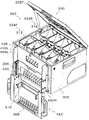
図1は、実施例のコイン自動整列補給装置(待機状態)の斜視図である。
図2は、上側の蓋を開放し、かつ、保持部を補給位置に移動した状態の実施例のコイン自動整列補給装置の斜視図である。
図3は、実施例のコイン自動整列補給装置(補給状態)の正面図である。
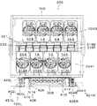
図4は、上側の蓋を除去した状態の実施例のコイン自動整列補給装置の平面図である。
図5は、実施例のコイン自動整列補給装置のシュート部の平面図である。
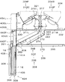
図6は、図3におけるA―A線断面図である。
図7は、実施例のコイン自動整列補給装置に用いるコインホッパの回転ディスクの中心を通る縦断面図である。
図8は、実施例の保留装置の補助カバーの斜視図である。
図9は、実施例の選択取付装置の正面側からの分解斜視図である。
図10は、実施例の選択取付装置の背面側からの分解斜視図である。
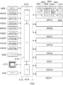
図11は、実施例の制御装置及びコインホッパの制御装置のブロック回路である。
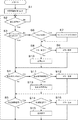
図12は、実施例の制御装置の作用説明用のメインフローチャートである。
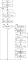
図13は、実施例のコインホッパの作用説明用のフローチャートである。
FIG. 1 is a perspective view of the coin automatic alignment and supply device (standby state) of the embodiment.
FIG. 2 is a perspective view of the coin automatic alignment and supply device of the embodiment in a state where the upper lid is opened and the holding unit is moved to the supply position.
FIG. 3 is a front view of the coin automatic alignment and supply device (supply state) according to the embodiment.
FIG. 4 is a plan view of the coin automatic alignment and replenishment apparatus according to the embodiment with the upper lid removed.
FIG. 5 is a plan view of the chute portion of the automatic coin alignment and replenishment device of the embodiment.
6 is a cross-sectional view taken along line AA in FIG.
FIG. 7 is a longitudinal sectional view passing through the center of the rotating disk of the coin hopper used in the automatic coin alignment and replenishment apparatus of the embodiment.
FIG. 8 is a perspective view of an auxiliary cover of the holding device according to the embodiment.
FIG. 9 is an exploded perspective view from the front side of the selective mounting device of the embodiment.
FIG. 10 is an exploded perspective view from the back side of the selective mounting device according to the embodiment.
FIG. 11 is a block circuit of the control device and the coin hopper control device of the embodiment.
FIG. 12 is a main flowchart for explaining the operation of the control device of the embodiment.
FIG. 13 is a flowchart for explaining the operation of the coin hopper according to the embodiment.
本実施例は、米国通貨の25セントコイン、10セントコイン、5セントコイン及び1セントコインの整列補給装置の例である。
図2に示すように、コイン整列補給装置300は、金種毎に設けられ、かつ、バラ積みに保留したコインを払い出すコインホッパ部304、コインホッパ部304の下方に位置し、コインホッパ部304から払い出されたコインをそれぞれ案内するシュート部306およびシュート部306の下方に位置し、かつ、シュート部306を滑り降りるコインを受け入れるコイン保留装置308を保持する保持部309とを含んでいる。
This embodiment is an example of an alignment supply device for 25 cent coin, 10 cent coin, 5 cent coin and 1 cent coin of US currency.
As shown in FIG. 2, the coin
コインホッパ部304及びシュート部306は、箱形のカバー302内に配置されている。
カバー302の前壁の開口310に相対して保持部309が選択的に位置可能に配置されている。
保持部309が選択的に位置されるため、コイン整列補給装置300は可及的に小型化できる。
The
A holding
Since the holding
まず、コインホッパ部304の構造を説明する。
コインホッパ部304には、バラ積み状態に保留したコインを一個ずつ区分けして払い出すコインホッパ312が少なくとも払い出す金種数に対応して配置されている。
したがって、本実施例においては4金種であるので、少なくとも4個のコインホッパ312が配置される。
しかし、本実施例においては、一金種を複数の保留部において保留するため、8個のコインホッパ312(同一数字にAからHを付加)が配置してある。
これらコインホッパ312Aから312Hは、全て同一構造であるので図7を参照して説明する。
First, the structure of the
In the
Therefore, since there are four denominations in this embodiment, at least four
However, in this embodiment, eight coin hoppers 312 (A to H are added to the same number) are arranged to hold one denomination in a plurality of holding units.
Since these
所定の間隔で並置された左フレーム311L及び右フレーム311R、傾斜状態で左右フレーム311L及び311Rに固定されたベース313、ベース313の上面に取り付けられた筒型のコインをバラ積み状態で保留する矩形のボウル314、そのボウル314の下部の円形孔315内で電気モータ316によって回転される回転ディスク318、ベース313の傾斜の上位側の円形孔315の側方に開口した払出口319及び払出口319に隣接配置したコインセンサ320を有している。
コインホッパ312として、米国デザイン特許第423589号に開示されるコインホッパを用いることが好ましい。
A
As the
払出口319に相対して上下方向に延びるガイド通路317を形成するチャンネル形のダクト321が左右フレーム311L、311Rに着脱可能に取り付けられている。
ダクト321のベース313に連なる壁面は、払出口319側から第1の角度で下降する第1斜面323、第1斜面323に続いて第1斜面323よりも大きな第2角度で下降する第2斜面325及び第2斜面325に続いてほぼ垂直に下方に延びる第1垂直面327を含んでいる。
A channel-shaped
The wall surface of the
これらに相対する面はほぼ垂直に伸びる第2垂直面329であり、第1垂直面327とコインの厚みの3から5倍の間隔で配置され、それらの間の下端が落下口331である。
ダクト321の幅は、図4に示すようにコインホッパ312の幅の約二分の一であり、使用される金種の最大コイン径の二倍以下の範囲、好ましくは最大コイン径の約1.5倍の幅で形成されている。
したがって、コインホッパ312とダクト321とは一体化されている。
The surfaces opposite to each other are a second
The width of the
Therefore, the
また、図4に示すように、コインホッパの前列324Fの払出口319Fと後列324Bの払出口319Bとが向かい、かつ、横方向にずらすことにより、ダクト321が僅かにオーバーラップして配置されている。
換言すれば、図6に示すように、ガイド通路317がオーバーラップして配置されている。
Also, as shown in FIG. 4, the
In other words, as shown in FIG. 6, the
このように、ダクト321をホッパ列324Fと324Bの列方向にずらして近接配置することにより、カバー302の幅を可及的に狭くできる。
また、前列324Fと後列324Bのダクト321を僅かにオーバーラップすることにより、カバー302の奥行寸法を短縮できる。
さらに、ガイド通路317を一列に配置することにより、その下方のシュートの入り口を一列に配置できるので、製作しやすい利点がある。
In this manner, the width of the
Further, the depth dimension of the
Furthermore, by arranging the
なお、実施例のコインホッパ312の回転ディスク318は、通孔322を4個以上有する。
通孔322が多い場合、コインが極めて短時間間隔で払い出されるため、積み重なって整列しない恐れがある。
この恐れを解消するため、モータ316の出力軸と回転ディスク318との間に配置される減速機321の減速比を大きくし、回転速度を低速にすることが好ましい。
コインが払い出される時間間隔を大きくすることにより、コインが保留部14(図8参照)において水平に整列する時間を簡単な構造で確保することができる。
Note that the
When there are many through-holes 322, coins are paid out at extremely short intervals, so there is a possibility that they will not be stacked and aligned.
In order to eliminate this fear, it is preferable to increase the reduction ratio of the
By increasing the time interval in which coins are paid out, coins can be ensured with a simple structure time to horizontally align the holding portion 14 (see FIG. 8).
この実施例において、統計的な金種別の消費量に応じてコイン保留装置308に金種別に保留するため、一金種で少なくとも2つの保留部が用意されている。
このため、コインホッパ312は図4に示すように、312Aから312Hの8個設けられ、四個ずつ前後に二列に所定の間隔で配置されている(保留される金種は、コインホッパ312のそれぞれに記入されている。)。
図6に示すように、前列324Fのコインホッパ312Aから312Dのコイン払出口319Fと後列324Bのコインホッパ312Eから312Hのコイン払出口319Bは、向かい合って配置され、図4に示すように整列方向にずれて配置されている。
In this embodiment, at least two holding units are prepared for one denomination in order to hold the
For this reason, as shown in FIG. 4, eight
As shown in FIG. 6, the
前列324Fのコインホッパ312Aには25セントコイン、コインホッパ312B及び312Cには1セントコイン及びコインホッパ312Dには10セントコインがバラ積み状態で保留される。
後列324Bのコインホッパ312Eには10セントコイン、コインホッパ312Fには1セントコイン、コインホッパ312Gには5セントコイン、コインホッパ312Hには25セントコインがバラ積み状態で保留される。
The
The
図1に示すように、カバー302の天板302Tには、各コインホッパにコインを補給するため、各コインホッパ312Aから312Hのボウル314の上部開口に相対して蓋328Aから328Hがピボット運動により開閉可能に設けられている。
図6に示すように、前列324Fのコインホッパ312Aから312Dは、カバー302の上下方向の中間部に水平に配置された中間第1ベース330に固定され、後列324Bのコインホッパ312Eから312Hは同様に配置された中間第2ベース332に固定されている。
As shown in FIG. 1,
As shown in FIG. 6, the
中間第1ベース330と中間第2ベース332は、所定の間隔333で並置され、中間第2ベース332は後述のベース396に固定されている。
なお、コインホッパ312は、コインを一個ずつ払い出す機能を有する回転ディスク318を用いない方式を用いることができる。
The intermediate
The
次にシュート部306を説明する。
シュート部306は、各コインホッパ312の払出口319F及び326Bの下方に位置し、各コインホッパ312から一個ずつ払い出されたコインを重力により落下させつつコイン保留装置308の所定の保留部14に個別に案内する機能を有している。
シュート部306は、前記ダクト321、コインホッパ312から払い出されたコインの勢いを減衰する緩衝装置336及びその緩衝装置336を経由して落下するコインをスライドさせて案内するスライド部338を含んでいる。
Next, the
The
The
図6に示すように、スライド部338は、第1の角度で傾斜する上側シュート部340及び第1角度よりも小さな第2角度で傾斜する下側シュート部342により構成されている。
上側シュート部340は、前列324Fと後列324Bとの間の落下口331の下方に位置してコインを受け入れる。
As shown in FIG. 6, the
図5に示すように、上側シュート部340は、一枚のシュート板348に所定の間隔で垂直に立てられた隔壁360によって8つに区分けされ、上下方向に伸びる通路である。
上側シュート部340の上端部は、ダクト321の落下口331の真下に位置し、それと同様の幅と奥行きを有し、落下口331から落下するコインを受け入れる。
As shown in FIG. 5, the
The upper end portion of the
下側シュート部342は、上端部が上側シュート部340の下方に位置し、下端部が前列324Fの下方に位置して斜め下方に伸びる図5に示すシュート板348、及び、図5に示す隔壁360によって形成された案内溝を有する。
換言すれば、各コインホッパ312Aから312Hに個別に対応して案内溝362Aから362Hが設けられている。
In other words, the
下側シュート部342のシュート板348は、図6に示すように、水平線に対し約25度傾斜しているが、20度から40度の範囲で設定することが好ましい。
この傾斜角度が40度を超える場合、コインの落下速度が大きく、保留部14での整列がうまく行われず、20度よりも小さい場合、コインの落下速度が小さく、自重で滑り落ちない恐れがあり、さらに、装置が大きくなるからである。
As shown in FIG. 6 , the
If this angle of inclination exceeds 40 degrees, the falling speed of the coins will be large, and the alignment at the holding
下側シュート部342における案内溝362Aから362Hの上端部は、上側シュート部340に連続し、それとほぼ同じ幅であり、下端部は、コイン保留装置308における対応する保留部14の上側に位置している。
換言すれば、図5に示すように案内溝362A、362E、362B、362Fと案内溝362H、362D、362G、362Cは、ダクト321の下位に位置し、かつ、中央を境に左右対称に形成されている。
The upper end portions of the
In other words, as shown in FIG. 5, the
次に緩衝装置336を説明する。
緩衝装置336は、コインホッパ312から払い出されたコインの勢いを減衰する機能を有している。
緩衝装置336は、簡単な構造で最大の効果を得るため、ガイド通路317の上部に第1緩衝装置363が配置されている。
第1緩衝装置363は、全て同一構造のため、図7を参照して説明する。
Next, the
The
The
The
第1緩衝装置363は、ダクト321の上端部に取り付けた第1軸364にガイド通路317をほぼ横断する板状の第1緩衝体366の上端部がピボット可能に取り付けられている。
第1軸364は、水平であって、コインホッパ312からのコインの払出方向に対しほぼ直交するように配置されている。
第1緩衝体366は、通常、図7に示すように自重により僅かに傾斜し、かつ、その下端部が第2斜面325とほぼコイン1枚の厚さ分離れた状態で静止している。
In the
The
As shown in FIG. 7, the
例えばコインホッパ312から払い出されたコインは、ベース313が上向きのため上向きに払い出される。
しかし、直ぐに失速して前下がり状態で第1緩衝体366に衝突する。
第1緩衝体366との衝突により勢いが減衰されたコインは、第1緩衝体366の下端により第2斜面325に押し付けられつつ滑り落ち、第2垂直面329に鈍角で衝突する。
衝突したコインは、下向きに転向され、ガイド通路317をほぼ垂直状態で落下する。
For example, coins paid out from the
However, the vehicle immediately stalls and collides with the
The coin whose momentum has been attenuated by the collision with the
The collided coin is turned downward and falls in the
次に第2緩衝装置370を図6を参照して説明する。
上側シュート部340の案内溝362Aから362Hのそれぞれに、第2緩衝装置370が配置されている。
第2緩衝装置370は、全て同一構造である。
第2緩衝装置370は、隔壁360の上端部に両端を支持された第2軸372に案内溝362をほぼ横断する板状の第2緩衝体374の上端部がピボット可能に取り付けられている。
Next, the
A
The
In the
第2軸372は、水平に配置されている。
第2緩衝体374は、通常、図6に示すように僅かに傾斜し、かつ、その下端部が上側シュート板348からほぼコインの厚み一枚部離れた状態で静止している。
ガイド通路317をほぼ垂直状態で落下するコインの先端は、上側シュート部340のシュート板348に衝突し、図6において左方へ転向された直後、第2緩衝体374に衝突し、勢いが減衰され、さらに、第2緩衝体374の下端によりシュート板348に押し付けられる。
The
The
The tip of the coin falling in the almost vertical state in the
結果、コインは下側シュート部342においてシュート板348に面接触しつつ滑り落ちる。
換言すれば、コインが勢いよく払い出されることによるシュート部306でのコインの暴れを抑制し、コインが所定の角度でコイン保留部308に達することができる。
なお、第1緩衝装置363により十分コインの暴れを防止できる場合、第2緩衝装置370は、配置されないことができる。
As a result, the coin slides down while making surface contact with the
In other words, it is possible to suppress the rampage of the coin in the
Note that the
次にコイン保留装置308を図8を参照して説明する。
コイン保留装置308は、金種毎にコインを一列に積み重ねて保留する保留部14を有する。
実施例において、板状の補助カバー382の左右端部を従来公知の本体16の左右のスライド溝20(右側のスライド溝は図示せず)に挿入して装着する。
この補助カバー382は、コイン払出用の下部開口26を除いて本体の側部開口12を覆っている。
Next, the
The
In the embodiment, the left and right end portions of the plate-like
The
側部開口12側に位置し、かつ、本体16よりも上方に伸び、かつ、各保留部14の延長に凹部390を形成した側壁388が補助カバー382の上端部に一体に成形されている。
側壁388の下側シュート部342側の下端部は、断面が三角形のリブ389(図6参照)によって接続されている。
A
The lower end of the
コインは、リブ389の上側の斜面391によって案内され、保留部14に落下する。
補助カバー382は、樹脂によって一体成型され、安価に製造される。
本体16に補助カバー382を装着して一体化し、コイン保留装置308を組み立てる。
この組み立て状態において、凹部390は保留部14の上位に連続して位置し、保留部14と凹部390が一つの円柱を形成している。
コイン保留装置308は保持部309(図3、図10参照)に装着され、その位置でコインの補充を受ける。
The coin is guided by the
The
An
In this assembled state, the recessed
The
次に保持部309を主に図1、9及び10を参照して説明する。
保持部309は、コイン保留装置308を所定の位置に保持する機能及び待機位置と補給位置に選択的に位置する機能を有している。
したがって、同様の機能を有する他の装置に変更することができる。
保持部309は、矩形凹部392を形成したスライドベース394の下端部の水平底部396、縦壁404、コイン保留装置308の位置規制体398、下部サポータ406及び可動ホルダ408、410を含んでいる。
Next, the holding
The holding
Therefore, it can be changed to another device having the same function.
The holding
位置規制体398は、水平底部396に固定されており、上向き凹部400及び後壁402を有する。
コイン保留装置308は、その下端部を位置規制体398の上向き凹部400と後壁402との間に填め込み、前後方向及び左右方向の位置決めがなされる。
この状態において、下部開口26は位置規制体398によって閉じられる。
また、本体16の背面をスライドベース394の縦壁404に固定した横長矩形の下部サポータ406にあてがって、下部の前後方向の位置決めをしている。
The
The
In this state, the
Further, the bottom of the
次に可動ホルダ408、410を説明する。
可動ホルダ408、410は、本体16の中間部を縦壁404の中間に配置したピボット運動可能な左右のフック状の可動ホルダ408及び410によって保持することにより、コイン保留装置308を所定位置に保持する機能を有する。
可動ホルダ408及び410は、左右対称であるため、可動ホルダ408を代表して説明する。
Next, the
The
Since the
図1に示すように、縦壁404の中間部に矩形の中間サポータ414が固定されている。
中間サポータ414は、図6に示すように、本体16の後壁に接触し、本体16の前後方向の位置を規制する。
図4に示すように、中間サポータ414の横端部において縦方向に伸びる支軸416に可動ホルダ408がピボット可能に取り付けられている。
可動ホルダ408の先端部には本体16を前側から押さえるようにフック418が形成されている。
As shown in FIG. 1, a rectangular
As shown in FIG. 6 , the
As shown in FIG. 4, a
A hook 418 is formed at the tip of the
可動ホルダ408の他端部(図示せず)に板バネ(図示せず)が係止され、可動ホルダ408に図4において反時計方向の回転力を与えている。
また、可動ホルダ408が図4において反時計方向に回動し、縦壁404に対しほぼ直角状態において、ストッパ(図示せず)が中間サポータ414の側面に係止され、その状態で静止する。
A leaf spring (not shown) is locked to the other end (not shown) of the
In addition, the
したがって、コイン保留装置308を中間サポータ414にあてがう場合、コイン保留装置308をほぼ垂立した状態にし、かつ、本体16の下端部を上向き凹部400に位置する位置規制体398と後壁402との間に嵌め込み、さらに中間サポータ414に本体16の後壁をあてがう。
Therefore, when the
この移動途中、本体16の後ろ側のコーナーが可動ホルダ408の斜面426に当接し、可動ホルダ408を時計方向に、また、可動ホルダ410を反時計方向に回動させる。
さらに本体16を押し進め、中間サポータ414に突き当てる。
保持部309が後述の補給位置にある場合、各保留部14は、各案内溝362Aから362Hの下端部の下方であって、かつ、その下端部が側壁388の側方に位置する。
During this movement, the rear corner of the
Further, the
When the holding
換言すれば、保留部14の上部開口18が図6に示すように、シュート板348の下端部404に隣接し、且つ、下方に位置している。
次いで、可動ホルダ408を手動で反時計方向に回動させ、可動ホルダ410を手動で時計方向に回動させることにより、フック418を本体16の前壁に係止する。
これにより、コイン保留装置308を保持部309に固定する。
In other words, as shown in FIG. 6, the
Next, the
Accordingly, the
次に保持部309の選択取付装置420を説明する。
実施例における選択取付装置420は、保持部309をカバー302の側壁に隣接した図1に示されている待機位置422及びコインを保留装置308に補給する図6に示されている補給位置424とに伸縮装置426によって保持部309を選択的に位置させることができる。
本実施例のように保持部309がカバー302に一体化された場合、保持部309の紛失を防止できる利点がある。
Next, the
The
When the holding
しかし、選択取付装置420は、コイン保留装置308を案内溝362Aから362Fの下方の所定位置に取付および取り外しできる機能を有していればよい。
換言すれば、コイン保留装置308が着脱可能な固定装置をカバー302に取り付けてもよい。
However, the
In other words, a fixing device to which the
次に伸縮装置426を主に図9及び図10を参照して説明する。
伸縮装置426は、保持部309を待機位置422と補給位置424に選択的に位置させる機能を有している。
したがって、伸縮装置426は、同様の機能を有する他の装置、例えば、エアシリンダに変更することができる。
Next, the
The
Therefore, the
実施例の伸縮装置426は、左伸縮装置426L及び右伸縮装置426Rを含み、それらは保持部309の左右に配置されるが、それらの構造は同一であるため、便宜的に左伸縮装置426Lを代表して説明し、右伸縮装置426Rの同一部品には同一数字にRを付し、説明を省略する。
なお、図面上左伸縮装置426Lに開示されない場合、適宜的に右伸縮装置426Rを参照して説明する。
図2に示すように、カバー302の前壁428にほぼ垂直に左ガイドプレート430Lが固定されている。
The expansion /
Note that, when not disclosed in the left
As shown in FIG. 2, the
左ガイドプレート430Lに対して上下方向にスライド可能にスライドプレート432が取り付けられている。
スライドプレート432の中央には、矩形の開口433が形成されている。
この開口433は、保持部309が補給位置424に位置する場合、下側シュート部342の下端部404に相対する。
これにより、案内溝362Aから362Hを滑り落ちたコインは、コイン保留装置308に落下することができる。
A
A
The
As a result, the coins that have slipped down the
スライドプレート432の両端部に前記左ガイドプレート430Lと右ガイドプレート430Rの内側に隣接して平行に伸びる左移動プレート432L及び右移動プレート432Rが形成されている。
左移動プレート432Lの外側に上下方向に伸びる外ガイドレール434A及び内側において上下方向に伸びる内ガイドレール434Bが固定されている。
外ガイドレール434Aの上端部に相対し、水平方向に伸びる第1上ストッパ436Fが左移動プレート432Lに固定され、下端部に相対し、水平方向に伸びる第1下ストッパ438Fが固定されている。
A left moving
An
A first
同様に、内ガイドレール434Bの上端部に相対し、かつ、水平方向に伸びる第2上ストッパ436Sが左移動プレート432Lに固定され、下端部に相対し、水平方向に伸びる第2下ストッパ438Sが固定されている。
右ガイドプレート430Rの下部内面に、水平方向に隣接並置された一対のベアリング440Fと440B、及び442Fと442Bよりなる移動ガイド444Rが配置されている。
これらベアリングは、給油の必要がないこと及び衝撃を緩衝できるため、樹脂製が好ましい。
Similarly, a second
A
These bearings are preferably made of resin because they do not need to be refueled and can cushion the impact.
外ガイドレール434Aが左右のベアリングの間に挟まれ、スライドプレート432が上下方向に平行移動可能である。
スライドプレート432が下方へ移動された場合、第1上ストッパ436Fがローラ440F及び440Bに停止される。
保持部309の左側壁446L及び右側壁446Rの上部に前記移動ガイド444Rと同様のローラベアリングからなる第2移動ガイド448Lが取り付けられている。
この第2移動ガイド448Lのローラ434F、134B及び438F,438B間に内ガイドレール434Bが配置され、保持部309がスライドプレート432に対し平行に上下動可能である。
The
When the
A
An
保持部309が下方に移動した場合、下側のローラ438F、438Bが第2下ストッパ438Sに停止される(図2、3及び図6の状態)。
保持部309の左側壁446L及び右側壁446Rに上部に待機保持装置450L(図9参照)及び450Rが配置されている。
待機保持装置450L及び450Rは、保持部309を待機位置422に保持する機能を有する。
したがって、同様の機能を有する他の装置に変更することができる。
When the holding
The
Therefore, it can be changed to another device having the same function.
本実施例において、待機保持装置450L及び450Rは、左側壁446L及び右側壁446Rに水平に移動可能に配置した段付きピン452L及び452R(図4参照)である。
これらピン452L、452Rは、スプリング(図示せず)により、内方に向かって押動され、大径部454L、454Rがガイドプレート430L、430Rの前縁上部に形成したノッチ456L、456Rにそれぞれ相対した位置で頭部の段部が左側壁446L、446Rに夫々停止される。
In the present embodiment, the
These
詳述すれば、段付きピン452L、452Rを側壁446L、446Rに押し込むよう移動させた場合、大径部454L、454Rがノッチ456L、456Rから外れ、保持部309が下方向に移動可能になる。
左右側壁446L、446Rの外側端面に横方向に向けてチャンネル状のハンドル458R,458L(図9参照)が固定されている。
保持部309は、このハンドル458R、458Lを持って上下方向に移動される。
したがって、ハンドル458R、458Lを持ってピン452L及び452Rを操作できるよう、ピン452L及び452Rは、ハンドル458R、458Lの上方近傍に配置されている。
More specifically, when the stepped pins 452L and 452R are moved so as to be pushed into the
Channel-shaped
The holding
Accordingly, the
次に、コイン保留装置308に所定金種を所定数補給するため、コインホッパ312Aから312Hからコインを払い出すための、コインホッパの払出制御ユニット460を説明する。
Next, a coin hopper
払出制御ユニット460は、第1ホッパ312Aから第8ホッパ412Hのそれぞれの払出数を設定する設定ユニット462Aから462H、各コインホッパの制御ユニット464Aから464Hをリセットするためのオートリセットボタン466、各コインホッパの制御ユニット464Aから464Hに払出処理を行わせるための払出ボタン468、ディスプレイ470、及び、前記設定ユニット及びボタン等の情報に基づいて制御ユニット464Aから464Hを制御し、かつ、それらからの情報を処理する処理装置472を含んでいる。
The
払出制御ユニット460が制御部に相当する。
なお、これらユニットは、パーソナルコンピュータのキーボード等によって代用することができる。
処理装置472は、払出ボタン468、処理プログラムを記憶するROM474、RAM476、マイクロプロセッサ478を含んでいる。
処理装置472は、ファイル形式の処理プログラムを実行する装置に変更することができる。
The
These units can be substituted by a keyboard of a personal computer.
The
The
ホッパ制御ユニット464Aから464Hは全て同一であるので464Aを代表して説明する。
ホッパ制御ユニット464Aは、処理ユニット482であり、処理装置472及びセンサ320から信号を受け、駆動回路490をオン・オフしてモータ316を駆動する。
なお、モーター316のオフに連動して電気ブレーキ492を制御し、回転ディスク318を急制動するようになっている。
Since all of the
The
The
処理ユニット482は、マイクロプロセッサ484、ROM484およびRAM486を含み、ROM484に記憶したプログラムに基づいて処理を行う。
また、処理ユニット482は、センサ320から信号を受け、払出したコインをカウントする機能を有している。
The
The
さらに、処理装置472から払出指示を受けた場合、駆動回路490をオンにしてモータ316に給電し、前記センサからの信号が払出指示数になった場合、駆動回路490をオフにしてモータ316への給電を停止し、かつ、電気ブレーキ回路492を作動させてモータ316を急停止させる。
Further, when a payout instruction is received from the
なお、処理ユニット482は、ロジック回路等、同一機能を有する他の装置に変更することができる。
また、ファイル形式の処理プログラムを処理装置472から転送し実行する装置に変更できる。
さらに、処理装置472は、同一金種のコインホッパに対し共通の指示信号を用いることができる。
Note that the
Further, the file format processing program can be changed from the
Furthermore, the
次に本実施例の作用を説明する。
まず、コイン整列補給装置300の作動に先立ち、保持部309を補給位置424に移動する。
すなわち、ハンドル458L及び458Rを小指、薬指、中指及び人差し指により握り、親指でピン452L、452Rの頭部を押し込み、ピン452L、452Rを内方へ移動させる。
Next, the operation of this embodiment will be described.
First, prior to the operation of the coin
That is, the
これにより、ピン452L、452Rの大径部がノッチ456L、456Rにから外れるので、保持部309を下方へ移動させることができる。
保持部309を下方へ移動させた場合、スライドプレート432は、上ストッパ436Fがローラ440B、440Fに停止されるまで移動できる。
さらに、保持部309は、第2移動ガイド448L、448Rが下ストッパ438Sに停止されるまで垂直下方に移動させることができる。
Accordingly, the large diameter portions of the
When the holding
Furthermore, the holding
上ストッパ436S及び下ストッパ438Sで停止された位置が補給位置424である。
この補給位置424において、補助カバー382を装着したコイン保留装置308を前述のように保持部309に保持させる。
The position stopped by the
At the
次に、各コインの払出数のセッティングを図12及び図13に示すフローチャートを参照して説明する。
まず、各コインホッパ毎の払出数が、払出数設定回路462Aから462Hにそれぞれプリセットされている。
例えば、各払出数設定回路462Aから462Hの全てに100がプリセットされている。
Next, setting of the number of coins to be paid out will be described with reference to the flowcharts shown in FIGS.
First, the number of payouts for each coin hopper is preset in each of the payout
For example, 100 is preset in all the payout
この払出数を変更する場合、払出数設定モードに切り替え、キーボード494を操作して新たな払出数を各払出数設定回路462Aから462Hに選択的に記憶する。
この払出数は、ファイル形式やデータテーブルとして記憶しておき、それらから選択して設定することができる。
When changing the number of payouts, the payout number setting mode is switched to, and a new payout number is selectively stored in each of the payout
The number of payouts can be stored as a file format or a data table, and can be selected and set from them.
まず、オートリセットボタン466を押した場合、処理装置472はステップS1において、各コインホッパの制御ユニット464Aから464Hの処理ユニット482と順次通信を行う。
処理ユニット482は、ステップH1において自己リセットする。
このとき、異常がある場合、ステップH2において異常信号が記憶される。
ステップH3において状態確認信号Cがあるか判別する。
First, when the auto-reset button 466 is pressed, the
The
At this time, if there is an abnormality, an abnormality signal is stored in step H2.
In step H3, it is determined whether or not there is a state confirmation signal C.
ステップH4において、状態確認信号Cがある場合、異常信号Eを出力する。
すなわち、異常信号を記憶している場合、異常信号Eを出力し、無い場合は正常信号Nを出力する。
次にステップH5において払出指示信号Dが有るか判別する。
払出信号Dが無い場合、ステップH2に戻る。
払出信号Dがある場合、ステップH6に進み、後述の払出処理を行う。
In step H4, when there is a state confirmation signal C, an abnormal signal E is output.
That is, when an abnormal signal is stored, an abnormal signal E is output, and when there is no abnormal signal, a normal signal N is output.
Next, in step H5, it is determined whether or not there is a payout instruction signal D.
If there is no payout signal D, the process returns to step H2.
If there is a payout signal D, the process proceeds to step H6, and payout processing described later is performed.
処理装置472のステップS2において、異常信号Eがあるか判別する。
ステップS2において異常信号Eが無い場合、ステップS2をループする。異常信号Eがある場合、ステップS3に進み、オートリセットボタン466の操作に基づく受信か判別し、 操作に基づく受信である場合、ステップS4に進む。
ステップS4において、払出ボタン468がオンになったか判別する。
払出ボタン468がオンの場合、後述の払出処理に進み、オフの場合、ステップS5に進む。
ステップS5において、払出要求信号の応答か判別し、その応答でない場合、ステップS2に戻る。
In step S2 of the
If the abnormality signal E is not in the step S2, looping through step S2. If there is an abnormal signal E , the process proceeds to step S3, where it is determined whether the reception is based on the operation of the auto-reset button 466. If the reception is based on the operation, the process proceeds to step S4.
In step S4, it is determined whether the
When the
In step S5, it is determined whether the response is a payout request signal. If not, the process returns to step S2.
ステップS3において、オートリセットボタン466の操作に基づかない受信の場合、ステップS6において、リセットが必要か判別する。
リセットが必要な場合、ステップS7に進み、各コインホッパの処理ユニット482にリセット指示のためのリセット信号Rを出力する。
リセットが必要でない場合、ステップS8に進み、各ホッパからの状態信号を判別し、異常信号Eを受信した場合、ステップS9に進み、ディスプレイ470に異常表示をした後、待機状態になる。
異常信号を受信しない場合、ステップS10に進み、ディスプレイ470に正常信号を表示した後、ステップS4に進む。
In step S3, if the reception is not steward groups on the operation of the automatic reset button 466, at step S6, to determine whether the reset is necessary.
If reset is necessary, the process proceeds to step S7, and a reset signal R for reset instruction is output to the
If the reset is not necessary, the process proceeds to step S8, the status signal from each hopper is determined, and if the abnormal signal E is received, the process proceeds to step S9, where an abnormal display is displayed on the
If no abnormal signal is received, the process proceeds to step S10, a normal signal is displayed on the
ステップS4において払出ボタン468がオンの場合、ステップS11に進む。
ステップS11において、各ホッパの払出数が所定値か判別し、所定値の範囲外の場合、ステップS12に進んでディスプレイ470にエラー表示をし、待機状態になる。
ステップS11において、各ホッパの払出数が適正な場合、ステップS13に進み、各ホッパに払出指示信号Dを出力し、その後ステップS5に進む。
If the
In step S11, it is determined whether the number of payouts of each hopper is a predetermined value. If it is out of the predetermined value range, the process proceeds to step S12, an error is displayed on the
If the number of payouts of each hopper is appropriate in step S11, the process proceeds to step S13, and a payout instruction signal D is output to each hopper, and then the process proceeds to step S5.
ホッパの処理ユニット482は、ステップH5において払出指示信号Dを受信した場合、ステップH6に進む。
ステップH6において、処理ユニット482は、払出指示数を記憶し、ステップH7において駆動回路490をオンにしてモーター316に電流を供給し、回転ディスク318を回転させる。
回転ディスク318の回転により、コインが一個ずつ払い出される。
When the
In step H6, the
As the
センサ320は、一個ずつ払い出されるコインを検知し、検知信号CUを出力する。
ステップH8において、検知信号CUの有無を判別し、検知信号CUがある場合ステップH8においてカウント処理を行う。
検知信号CUが無い場合、待機状態になる。
The
In step H8, the presence / absence of the detection signal CU is determined. If the detection signal CU is present, the count process is performed in step H8.
When there is no detection signal CU, it enters a standby state.
次にステップH10において、カウント値と記憶されている払出指示数を比較する。
払出指示数に満たない場合、ステップH7に戻り、指示数に等しくなった場合、ステップH11に進んで駆動回路490をオフにし、モータ316への電流供給を遮断するとともにブレーキ回路492を所定時間作動させてモータ316を急停止させ、コインの払い出しを停止する。
次いでステップH12において、払出済み数信号Fを出力し、ステップH2に戻る。
Next, in step H10, the count value is compared with the stored number of payout instructions.
If less than the number of payout instructions, return to step H7, if equal to the number of instructions, proceed to step H11 to turn off the
Next, in step H12, the paid-out number signal F is output, and the process returns to step H2.
ステップS5において、払出済み数信号Fを判別した場合、ステップS14に進む。
ステップS14において、ホッパの払出指示数と払出済み数が等しい場合、ステップS15に進んでディスプレイ470に正常表示をした後、ステップS2に戻る。
ステップS14において、両者が一致しない場合、ステップS16に進んでディスプレイ470にエラー表示して待機状態になる。
If it is determined in step S5 that the paid-out number signal F has been reached, the process proceeds to step S14.
If it is determined in step S14 that the number of payout instructions issued by the hopper is equal to the number of payouts, the process proceeds to step S15 to display the normal on the
If they do not match in step S14, the process proceeds to step S16, an error is displayed on the
次にコインホッパ312から払い出されたコインの動きを説明する。
まず、前列324Fのコインホッパ340Aから340Dから払い出されるケースを図6を参照して説明する。
コインホッパ312Aから312Dの払出口319から払い出されたコインは、放物線を描いて落下し、その先端が第1緩衝体366と鈍角に衝突する。
Next, the movement of coins paid out from the
First, a case in which the coin hoppers 340A to 340D in the
The coins paid out from the
コインが鈍角に衝突するため、そのコインは第1緩衝体366によって下方へ強制的に移動され、第2斜面325に面接しつつ滑り落ちる。
次いでコインの先端は、第2垂直面329に鈍角に衝突して下方へ向けられるので、コインはガイド通路317にほぼ垂直に落下する。
コインは、第1緩衝体366への衝突により、運動エネルギーが吸収される。
Since the coin collides with an obtuse angle, the coin is forcibly moved downward by the
Next, since the tip of the coin collides with the second
The kinetic energy of the coin is absorbed by the collision with the
ガイド通路317を落下したコインは、上側シュート部340のシュート板348に鈍角に衝突し、図6において左方へ案内される。
この衝突で跳ねたコインは、第2緩衝体374の下端部に衝突するので、上側シュート部340に押し付けられる。
したがって、コインは、上側シュート部340に面接触しつつ下側シュート部342へ滑り落ちる。
The coin that has fallen through the
The coins bounced by the collision collide with the lower end portion of the
Therefore, the coin slides down to the
第2緩衝体374に衝突し、それを揺らすことによりコインの運動エネルギーが吸収され、コインは速やかに上側シュート部340に面接触しつ落下するようになる。
下側シュート部340の案内溝362Aから362Hを滑り落ちたコインは、補助カバー382の側壁388に衝突する。
コインは、樹脂によりその衝撃を吸収されるので、ほぼ水平状態で保留部14内に落下し、その底部に静止する。
つぎに払い出されたコインは、回転ディスク318の回転速度が小さいので、十分な時間間隔を有している。
By colliding with the
Coins that have slipped down the
Since the impact of the coin is absorbed by the resin, the coin falls into the holding
The coins paid out next have a sufficient time interval because the rotational speed of the
したがって、コインが連続して払い出された場合であっても、前に払い出されたコインがほぼ水平になるまで落下しないので、コインは確実に積み上がる。
後列324Bのコインホッパから払い出されるコインも前列324Fから払い出されたコインと同様に保留部14内に保留される。
コインの払出が終了した後、可動ホルダ408及び410を回動させてコイン保留装置308を保持部309から取り出し、補助カバー382を本体16から取り外し、従来のカバー22を取り付けることにより、前述の釣り銭払出装置において利用することができる。
Therefore, even if coins are continuously paid out, the coins that have been paid out before do not fall until they are almost horizontal, so that the coins are surely stacked.
The coins paid out from the coin hopper in the
After the coins are paid out, the
コインの補給作業が終了した場合、保持部309を待機位置422に戻す。
すなわち、ハンドル458L、458Rを前述のように持ち、ピン452L、452Rを外方向に移動させ、その状態で上方に持ち上げる。
この過程で、第2補助ガイド448L、448Rが上ストッパ436Sを押し上げ、スライドプレート432を一体的に移動させる。
次いで、ピン452L、452Rがノッチ456L、456Rに達した位置でピン452L、452Rを離すことにより、ピン452L、452Rがスプリング(図示せず)により復帰動し、大径部454L、454Rがノッチ456L、456Rに相対するため、待機位置422に保持部309は保持される。
When the coin supply operation is completed, the holding
That is, the
In this process, the second auxiliary guides 448L and 448R push up the
Next, when the
14 コイン保留部
302 カバー
306 シュート部
308 コイン保留装置
309 保持部
312A〜312H コインホッパ
313 傾斜ベース
317 ガイド通路
318 回転ディスク
319 払出口
366 板状体
382 カバー
420 選択取付装置
424 補給位置
422 待機位置
460 制御部
14 Coin holding part
302 cover
306 Shooting part
308 Coin holding device
309 Holding part
312A-312H Coin Hopper
313 inclined base
317 Guide passage
318 rotating disc
319 exit
366 Plate
382 Cover
420 Selective mounting device
424 Supply position
422 Standby position
460 Control unit
Claims (3)
コインをバラ積み状態で保留する金種毎のコインホッパ(312A〜312H)、
前記コインホッパの下方に位置し、上部が前記コインホッパの所定の払出口(319)に接続され、かつ、下部が前記コイン保留装置の所定の保留部に接続されたシュート部(306)、
前記コインホッパと前記シュート部を内蔵する箱形のカバー(302)、
前記カバーに取り付けられた選択取付装置(420)によって前記シュート部の下方に位置する補給位置(424)と前記シュート部に並列した待機位置(422)に選択的に位置可能である保持部(309)、
前記各コインホッパのコイン払出数を制御する制御部(460)、
とを備えるコイン自動整列補給装置。 In a coin automatic alignment and replenishment device that automatically replenishes coins to a coin retention device (308) in which a plurality of cylindrical coin retention portions (14) are arranged in parallel,
Coin hopper (312A-312H) for each denomination that holds coins in bulk
A chute (306), which is located below the coin hopper, the upper part is connected to a predetermined payout opening (319) of the coin hopper, and the lower part is connected to a predetermined holding part of the coin holding device,
A box-shaped cover (302) containing the coin hopper and the chute part;
A holding part (309 ) that can be selectively positioned at a replenishment position (424) located below the chute part and a standby position (422) parallel to the chute part by a selective attachment device (420) attached to the cover. ),
A control unit (460) for controlling the number of coins to be paid out by each coin hopper,
A coin automatic alignment and supply device.
Priority Applications (5)
| Application Number | Priority Date | Filing Date | Title |
|---|---|---|---|
| JP2004092103A JP4604165B2 (en) | 2004-03-26 | 2004-03-26 | Automatic coin replenishment device |
| EP11157266A EP2343688A1 (en) | 2003-10-21 | 2004-10-12 | Automatic coin aligning apparatus and method |
| EP04256292A EP1526483B1 (en) | 2003-10-21 | 2004-10-12 | Automatic coin aligning apparatus |
| US10/966,601 US7419042B2 (en) | 2003-10-21 | 2004-10-15 | Automatic coin aligning apparatus and method |
| US11/771,880 US7429213B2 (en) | 2003-10-21 | 2007-06-29 | Automatic coin aligning apparatus and method |
Applications Claiming Priority (1)
| Application Number | Priority Date | Filing Date | Title |
|---|---|---|---|
| JP2004092103A JP4604165B2 (en) | 2004-03-26 | 2004-03-26 | Automatic coin replenishment device |
Publications (3)
| Publication Number | Publication Date |
|---|---|
| JP2005276102A JP2005276102A (en) | 2005-10-06 |
| JP2005276102A5 JP2005276102A5 (en) | 2007-05-17 |
| JP4604165B2 true JP4604165B2 (en) | 2010-12-22 |
Family
ID=35175678
Family Applications (1)
| Application Number | Title | Priority Date | Filing Date |
|---|---|---|---|
| JP2004092103A Expired - Fee Related JP4604165B2 (en) | 2003-10-21 | 2004-03-26 | Automatic coin replenishment device |
Country Status (1)
| Country | Link |
|---|---|
| JP (1) | JP4604165B2 (en) |
Families Citing this family (2)
| Publication number | Priority date | Publication date | Assignee | Title |
|---|---|---|---|---|
| KR200452478Y1 (en) * | 2009-05-12 | 2011-02-28 | 주식회사 이티엠 | apparatus for filling a coin |
| JP5678591B2 (en) * | 2010-11-11 | 2015-03-04 | 富士電機株式会社 | Coin processing equipment |
Citations (5)
| Publication number | Priority date | Publication date | Assignee | Title |
|---|---|---|---|---|
| US3590833A (en) * | 1968-08-08 | 1971-07-06 | Swd Machines Inc | Coin-handling apparatus |
| JPH0374077U (en) * | 1989-11-21 | 1991-07-25 | ||
| JP2002298188A (en) * | 2001-03-30 | 2002-10-11 | Takamisawa Cybernetics Co Ltd | Coin processor |
| US20030013403A1 (en) * | 2001-06-01 | 2003-01-16 | Blake John R. | Coin holding device for filling coin cassettes |
| JP2003051039A (en) * | 2001-08-03 | 2003-02-21 | Laurel Seiki Kk | Coin runaway proofing device for coin cassette |
Family Cites Families (7)
| Publication number | Priority date | Publication date | Assignee | Title |
|---|---|---|---|---|
| JPS5279996U (en) * | 1975-12-11 | 1977-06-15 | ||
| US4275751A (en) * | 1979-05-10 | 1981-06-30 | Brandt, Inc. | Coin sorter with expanded capability |
| JPS64166U (en) * | 1987-06-17 | 1989-01-05 | ||
| JP2904816B2 (en) * | 1989-08-15 | 1999-06-14 | グローリー工業株式会社 | Securities settlement system |
| JP2750563B2 (en) * | 1993-07-09 | 1998-05-13 | 重悦 柏谷 | Coin payout device |
| JP3779821B2 (en) * | 1998-06-10 | 2006-05-31 | グローリー工業株式会社 | Coin handling machine |
| US20030024790A1 (en) * | 2001-07-31 | 2003-02-06 | Quattrini Victor A. | Apparatus for monitoring coins discharged from a coi dispenser |
-
2004
- 2004-03-26 JP JP2004092103A patent/JP4604165B2/en not_active Expired - Fee Related
Patent Citations (5)
| Publication number | Priority date | Publication date | Assignee | Title |
|---|---|---|---|---|
| US3590833A (en) * | 1968-08-08 | 1971-07-06 | Swd Machines Inc | Coin-handling apparatus |
| JPH0374077U (en) * | 1989-11-21 | 1991-07-25 | ||
| JP2002298188A (en) * | 2001-03-30 | 2002-10-11 | Takamisawa Cybernetics Co Ltd | Coin processor |
| US20030013403A1 (en) * | 2001-06-01 | 2003-01-16 | Blake John R. | Coin holding device for filling coin cassettes |
| JP2003051039A (en) * | 2001-08-03 | 2003-02-21 | Laurel Seiki Kk | Coin runaway proofing device for coin cassette |
Also Published As
| Publication number | Publication date |
|---|---|
| JP2005276102A (en) | 2005-10-06 |
Similar Documents
| Publication | Publication Date | Title |
|---|---|---|
| US7429213B2 (en) | Automatic coin aligning apparatus and method | |
| JP3994131B2 (en) | Coin dispensing device | |
| US5902178A (en) | Coin sorting apparatus | |
| US5098339A (en) | Coin feeding device | |
| JPH0445100Y2 (en) | ||
| JP4604165B2 (en) | Automatic coin replenishment device | |
| JP4423366B2 (en) | Automatic coin replenishment device | |
| JPH061752Y2 (en) | Discharge device for disk | |
| JP2002260047A (en) | Coin change machine | |
| JP7102497B2 (en) | Input article detection device and container removal device | |
| JP6817980B2 (en) | Input article sorting device, input article detection device and container removal device | |
| JP6183614B2 (en) | Coin sorting device and coin sorting device equipped with the coin sorting device | |
| JPH04316190A (en) | Expanded tank of replenishing type medal delivering mechanism | |
| JPH05174222A (en) | Coin mechanism | |
| JP4129542B2 (en) | Coin dispensing device and coin mech coin dispensing device | |
| JP4129541B2 (en) | Coin mech coin dispensing device | |
| JP3172349B2 (en) | Coin dispenser | |
| JP3547389B2 (en) | vending machine | |
| JP3084646B2 (en) | Coin dispenser | |
| JP2517328B2 (en) | Coin dispenser | |
| JP2517350B2 (en) | Coin dispenser | |
| JP3476943B2 (en) | A money changer that can switch between coin payout and collection | |
| JP2015210738A5 (en) | ||
| JP5467920B2 (en) | Game machine | |
| JP4665094B2 (en) | Coin mech |
Legal Events
| Date | Code | Title | Description |
|---|---|---|---|
| A521 | Request for written amendment filed |
Free format text: JAPANESE INTERMEDIATE CODE: A523 Effective date: 20070323 |
|
| A621 | Written request for application examination |
Free format text: JAPANESE INTERMEDIATE CODE: A621 Effective date: 20070323 |
|
| A977 | Report on retrieval |
Free format text: JAPANESE INTERMEDIATE CODE: A971007 Effective date: 20100205 |
|
| A131 | Notification of reasons for refusal |
Free format text: JAPANESE INTERMEDIATE CODE: A131 Effective date: 20100319 |
|
| A521 | Request for written amendment filed |
Free format text: JAPANESE INTERMEDIATE CODE: A523 Effective date: 20100514 |
|
| TRDD | Decision of grant or rejection written | ||
| A01 | Written decision to grant a patent or to grant a registration (utility model) |
Free format text: JAPANESE INTERMEDIATE CODE: A01 Effective date: 20100902 |
|
| A01 | Written decision to grant a patent or to grant a registration (utility model) |
Free format text: JAPANESE INTERMEDIATE CODE: A01 |
|
| A61 | First payment of annual fees (during grant procedure) |
Free format text: JAPANESE INTERMEDIATE CODE: A61 Effective date: 20100903 |
|
| R150 | Certificate of patent or registration of utility model |
Ref document number: 4604165 Country of ref document: JP Free format text: JAPANESE INTERMEDIATE CODE: R150 Free format text: JAPANESE INTERMEDIATE CODE: R150 |
|
| FPAY | Renewal fee payment (event date is renewal date of database) |
Free format text: PAYMENT UNTIL: 20131015 Year of fee payment: 3 |
|
| R250 | Receipt of annual fees |
Free format text: JAPANESE INTERMEDIATE CODE: R250 |
|
| R250 | Receipt of annual fees |
Free format text: JAPANESE INTERMEDIATE CODE: R250 |
|
| R250 | Receipt of annual fees |
Free format text: JAPANESE INTERMEDIATE CODE: R250 |
|
| R250 | Receipt of annual fees |
Free format text: JAPANESE INTERMEDIATE CODE: R250 |
|
| R250 | Receipt of annual fees |
Free format text: JAPANESE INTERMEDIATE CODE: R250 |
|
| R250 | Receipt of annual fees |
Free format text: JAPANESE INTERMEDIATE CODE: R250 |
|
| R250 | Receipt of annual fees |
Free format text: JAPANESE INTERMEDIATE CODE: R250 |
|
| R250 | Receipt of annual fees |
Free format text: JAPANESE INTERMEDIATE CODE: R250 |
|
| LAPS | Cancellation because of no payment of annual fees |