JP4604117B2 - Personal authentication apparatus and method - Google Patents
Personal authentication apparatus and method Download PDFInfo
- Publication number
- JP4604117B2 JP4604117B2 JP2008287286A JP2008287286A JP4604117B2 JP 4604117 B2 JP4604117 B2 JP 4604117B2 JP 2008287286 A JP2008287286 A JP 2008287286A JP 2008287286 A JP2008287286 A JP 2008287286A JP 4604117 B2 JP4604117 B2 JP 4604117B2
- Authority
- JP
- Japan
- Prior art keywords
- finger
- light
- light source
- image
- imaging unit
- Prior art date
- Legal status (The legal status is an assumption and is not a legal conclusion. Google has not performed a legal analysis and makes no representation as to the accuracy of the status listed.)
- Active
Links
- 238000000034 method Methods 0.000 title description 37
- 238000003384 imaging method Methods 0.000 claims description 62
- 238000007664 blowing Methods 0.000 claims description 14
- 210000004204 blood vessel Anatomy 0.000 claims description 8
- 238000000605 extraction Methods 0.000 claims description 6
- 238000012937 correction Methods 0.000 claims description 4
- 230000000007 visual effect Effects 0.000 claims 1
- 210000003462 vein Anatomy 0.000 description 50
- 210000000282 nail Anatomy 0.000 description 11
- 238000012545 processing Methods 0.000 description 11
- 230000002411 adverse Effects 0.000 description 9
- 238000010586 diagram Methods 0.000 description 9
- 230000000694 effects Effects 0.000 description 7
- 238000001514 detection method Methods 0.000 description 4
- 230000006870 function Effects 0.000 description 4
- 238000009434 installation Methods 0.000 description 4
- 230000002708 enhancing effect Effects 0.000 description 3
- 238000002474 experimental method Methods 0.000 description 3
- 230000001965 increasing effect Effects 0.000 description 3
- 230000001678 irradiating effect Effects 0.000 description 3
- 125000002066 L-histidyl group Chemical group [H]N1C([H])=NC(C([H])([H])[C@](C(=O)[*])([H])N([H])[H])=C1[H] 0.000 description 2
- 230000000903 blocking effect Effects 0.000 description 2
- 238000005516 engineering process Methods 0.000 description 2
- 230000003287 optical effect Effects 0.000 description 2
- 102000001554 Hemoglobins Human genes 0.000 description 1
- 108010054147 Hemoglobins Proteins 0.000 description 1
- 238000005452 bending Methods 0.000 description 1
- 239000008280 blood Substances 0.000 description 1
- 210000004369 blood Anatomy 0.000 description 1
- 238000011840 criminal investigation Methods 0.000 description 1
- 238000011156 evaluation Methods 0.000 description 1
- 210000004905 finger nail Anatomy 0.000 description 1
- 210000000554 iris Anatomy 0.000 description 1
- 239000000203 mixture Substances 0.000 description 1
- 229920006395 saturated elastomer Polymers 0.000 description 1
- 238000009423 ventilation Methods 0.000 description 1
- 230000003313 weakening effect Effects 0.000 description 1
Images


Description
本発明は生体を用いた個人認証装置に関し、特に、生体を透過した光を撮像して得られ
る血管パターンを利用して認証する装置に関する。
The present invention relates to a personal authentication apparatus using a living body, and more particularly to an apparatus for performing authentication using a blood vessel pattern obtained by imaging light transmitted through a living body.
個人の所有物や情報に対するセキュリティ技術に対する関心が高まる中、盗難や紛失に
よる不正使用の危険が少なく、利便性が高い個人認証技術として指紋、虹彩、静脈など、
人間の生体情報を利用して認証を行う生体認証技術が注目されている。中でも、指の血管
パターンの違いを利用して個人を識別する指静脈認証技術は、指紋のように犯罪捜査を連
想させることがないため心理的抵抗感が少なく、生体内部の特徴を使うために盗難のリス
クが小さいという特徴を持つ。
While interest in security technologies for personal property and information is increasing, there are few risks of unauthorized use due to theft or loss, and fingerprints, irises, veins,
A biometric authentication technique that performs authentication using human biometric information has attracted attention. Above all, finger vein authentication technology that identifies individuals by using the difference in finger blood vessel pattern has little psychological resistance because it does not resemble a criminal investigation like a fingerprint, so that it uses features inside the living body. It is characterized by a low risk of theft.
指静脈を利用した認証は次のように実現される。指に赤外光を照射すると、光は指内部
で散乱した後、外部へ放射していく。このとき、血液中のヘモグロビンは周囲組織と比較
して赤外光をより吸収するため、指を透過した光を撮像すると、指の皮下に分布する血管
、すなわち指静脈が暗い影のパターンとなって可視化される。この画像から得た指静脈パ
ターンの特徴データを事前に登録しておき、提示された指の画像から得た指静脈パターン
の特徴データとの相関を求めることで登録者か否かを判定し、個人認証を行う。
Authentication using the finger vein is realized as follows. When the finger is irradiated with infrared light, the light is scattered inside the finger and then emitted to the outside. At this time, hemoglobin in the blood absorbs infrared light more than the surrounding tissue, so when imaging light transmitted through the finger, blood vessels distributed under the finger, that is, the finger veins, have a dark shadow pattern. And visualized. The feature data of the finger vein pattern obtained from this image is registered in advance, and it is determined whether or not it is a registrant by obtaining the correlation with the feature data of the finger vein pattern obtained from the presented finger image, Perform personal authentication.
従来の指静脈認証装置では、利用者が指を再現よく提示できるようにするために、認証
装置に指の位置を固定するためのガイド部を設置している。このガイド部に指を提示する
ことで、撮影される静脈の画像の再現性が高くなり、高精度な認証が可能である。また、
指の提示位置が安定するため、光源の光を確実に指に照射することができ、指の周辺から
強い光が漏れることがない。これにより鮮明な静脈パターン画像の撮影が可能である。し
かし、従来装置は認証を行う際に指と装置を一部接触させる必要があり、衛生を重視する
環境での利用が難しい。
In the conventional finger vein authentication device, a guide unit for fixing the finger position is installed in the authentication device so that the user can present the finger with good reproducibility. By presenting the finger on the guide unit, the reproducibility of the captured vein image is enhanced, and high-accuracy authentication is possible. Also,
Since the finger presentation position is stable, the light from the light source can be reliably irradiated onto the finger, and strong light does not leak from the periphery of the finger. As a result, a clear vein pattern image can be taken. However, it is necessary for the conventional apparatus to make a part of contact between the finger and the apparatus when performing authentication, and it is difficult to use in an environment in which hygiene is important.
この問題を解決する認証装置として完全非接触で静脈の画像を獲得し、認証を行う個人
認証装置が特許文献1に開示されている。非接触の認証装置ではガイド部に触れて指の位
置決めを行うことができないため指の提示位置が変動しやすく、撮像画像の再現性が低く
なる。そのため、この認証装置では、撮像画像内の指の輪郭を用いて回転補正を行う手段
と、指先の位置を基準として正規化する手段を備えている。これにより、撮像画像内での
指の位置が変動する場合でも認証を可能としている。
As an authentication apparatus that solves this problem, Patent Document 1 discloses a personal authentication apparatus that acquires and verifies a vein image in a completely non-contact manner. In the non-contact authentication device, the finger cannot be positioned by touching the guide portion, so the finger presentation position is likely to change, and the reproducibility of the captured image is lowered. Therefore, this authentication apparatus includes means for performing rotation correction using the contour of the finger in the captured image and means for normalizing with the position of the fingertip as a reference. This enables authentication even when the position of the finger in the captured image varies.
しかし、指の提示位置の変動によって起こる問題は、撮像画像内での指位置の再現性が
悪くなることだけではない。指の提示位置が安定しない認証装置では、光源からの光を確
実に指のみに照射することが困難になる。そのため、本来指に照射されるはずの強い光が
指の周囲へ漏れ出し、撮像部そのものに悪影響を与える。例えば、撮像部に強い漏れ光が
照射されると、レンズやフィルタなどの光学部品で反射が起こり、部品そのものの影が映
り込む。また、撮像素子に対するスミアノイズなどが発生することもある。このような漏
れ光による撮像部への悪影響は、光源から出力する光を弱くすることで抑えられるが、そ
の場合、指を透過する光も減少するため静脈画像を獲得できなくなる。漏れ光による悪影
響を防ぐ別の方法として、入力インターフェース上に遮光手段を設置し撮像部に入射する
漏れ光を遮る方法も考えられる。しかし、非接触の認証装置では指の提示位置が変動しや
すく、指の位置によっては、遮光手段が漏れ光だけでなく指を透過した光も遮ってしまう
場合がある。このように遮光手段は、静脈画像獲得の障害となる場合があるため設置する
ことができない。
However, the problem caused by the fluctuation of the finger presentation position is not only that the reproducibility of the finger position in the captured image is deteriorated. In an authentication device in which the finger presentation position is not stable, it is difficult to reliably irradiate only the finger with light from the light source. For this reason, strong light that should originally be applied to the finger leaks around the finger and adversely affects the imaging unit itself. For example, when strong leakage light is irradiated on the imaging unit, reflection occurs in optical components such as a lens and a filter, and a shadow of the component itself is reflected. In addition, smear noise or the like for the image sensor may occur. Such an adverse effect on the imaging unit due to the leaked light can be suppressed by weakening the light output from the light source, but in this case, the light transmitted through the finger is also reduced, and a vein image cannot be acquired. As another method for preventing an adverse effect due to leaked light, a method of blocking the leaked light incident on the imaging unit by installing a light shielding unit on the input interface is also conceivable. However, in the non-contact authentication apparatus, the finger presentation position is likely to fluctuate, and depending on the finger position, the light shielding means may block not only leaked light but also light transmitted through the finger. In this way, the light shielding means cannot be installed because it may be an obstacle to obtaining a vein image.
本発明では、衛生を重視する環境下で利用でき、かつ利用者に対し装置形状による圧迫
感を与えることなく個人認証を実施するために、生体の提示位置が開放的で、
かつ生体の提示位置が変動しても撮像部に光源からの強い漏れ光を照射することなく適切
な光を生体に照射し、鮮明な静脈画像が獲得できる完全非接触型の静脈認証装置の実現を
目的とする。
In the present invention, in order to perform personal authentication without giving a sense of pressure due to the shape of the device to the user in an environment that places importance on hygiene, the living body presentation position is open,
Realization of a completely non-contact type vein authentication device that can irradiate the living body with appropriate light without irradiating the imaging unit with strong light leakage from the light source even when the presentation position of the living body changes, and acquire a clear vein image With the goal.
上記の目的を達成するために、赤外光を発光する光源と、該光源からの光によって生体
の静脈画像を撮像する撮像部を備えた入力インターフェースと、照射する光の強さを制御
する手段と、画像から特徴抽出と特徴照合を行う画像演算部と、生体を提示する位置決め
手段とを設ける。特に、前記光源は前記生体の前方に設け、さらに、前記撮像部に対して
悪影響を与えない向きに設置することを特徴とする。
In order to achieve the above object, a light source that emits infrared light, an input interface that includes an imaging unit that captures a vein image of a living body using light from the light source, and means for controlling the intensity of light to be irradiated And an image calculation unit that performs feature extraction and feature matching from the image, and a positioning unit that presents the living body. In particular, the light source is provided in front of the living body, and further installed in a direction that does not adversely affect the imaging unit.
本発明によれば、衛生を重視する環境下で利用でき、かつ利用者に対し装置形状による
圧迫感を与えずに認証を行える完全非接触型の静脈認証装置を実現することができる。
According to the present invention, it is possible to realize a completely non-contact type vein authentication device that can be used in an environment where importance is placed on hygiene and can perform authentication without giving the user a feeling of pressure due to the shape of the device.
以下、本発明の実施の形態を図面を参照して説明する。尚、本実施例においては特に指
の静脈認証装置について説明するが、掌等、照射された光が生体の内部を通過して生成さ
れる画像を使った認証を行う他の生体であっても適応可能である。
Hereinafter, embodiments of the present invention will be described with reference to the drawings. In this embodiment, the finger vein authentication device will be described in particular. However, even with other living bodies such as palms, which perform authentication using an image generated by the irradiated light passing through the inside of the living body. Adaptable.
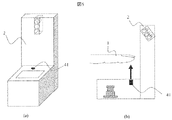
図1(a)は、本発明を実現する非接触型指静脈認証装置の構成の概略図である。図1
(b)は図1(a)のメモリ12、記憶装置14を詳細に示したものである。
FIG. 1A is a schematic diagram of a configuration of a non-contact type finger vein authentication device that realizes the present invention. FIG.
(B) shows the
利用者が指を提示する部分である指静脈パターンの入力インターフェース2には、赤外
光源3と撮像部4が備えられている。利用者が入力インターフェースに指を提示すると、
光源3より指1に対して光が照射される。光は指1の内部で散乱し、指1を透過した光が
撮像部4によって撮影される。光は撮像部4により電気信号に変換され、画像入力手段1
8を介し画像として認証処理部10に取り込まれる。取り込まれた画像はインターフェー
ス13を介しメモリ12に記憶される。また事前に登録されている登録データ200が記
憶装置14より認証処理部10のメモリ12に格納される。このとき、複数の登録者の登
録データ200をメモリ12に格納してもよく、入力部16によって入力された利用者I
D等の情報に対応した登録データ200のみを格納してもよい。CPU11はメモリ12
に格納された認証プログラム100に従って、入力画像から認証データ250を作成し、
登録データ200との照合を行う。照合処理では比較する2つのデータ間の相関を算出し
、その値に応じて登録されているデータと一致するかを判定する。この結果に応じて個人
を認証する。認証結果は表示部15に表示を行う、またはスピーカ17から音声を発信す
ることで利用者に伝えられる。正しく認証された場合は認証システムの制御対象に対して
認証時の処理を行う。
An
Light is applied to the finger 1 from the
8 and is taken into the
Only
The
Collation with registered
図2は、本発明を実現する非接触型指静脈認証装置の入力インターフェース2の一構成
例である。なお、以下の説明および請求項等においては、指提示位置が撮像部よりも高い
位置にあり、光源がその指提示位置よりも更に高い位置にあると説明している。しかし、
これは理解の容易のための説明であり、撮像部、指提示位置、および光源の相対的な位置
関係や光の入射角度関係等が保たれて所望の効果が得られれば、全体が異なる角度で(例
えばユーザ側に傾けて)設置される、光源が設置される奥の壁が撮像部に対して90度以
外の角度をなす、などの形態も本発明の範疇に含まれる。
FIG. 2 is a configuration example of the
This is an explanation for easy understanding, and if the desired position is obtained by maintaining the relative positional relationship between the imaging unit, the finger presentation position, and the light source, the incident angle relationship of light, etc., the entire angle is different. The configuration of the present invention is also included in the scope of the present invention, such as being installed at an angle (for example, tilted toward the user side), or the back wall where the light source is installed is at an angle other than 90 degrees with respect to the imaging unit.
入力インターフェース2は利用者が指1をかざすことで指の静脈画像を獲得する。利用
者が指1をかざしたときに掌側の静脈パターンを撮影するために、撮像部4は指の提示位
置の下側(手のひら側)に設置する。撮像部4には不要な光を遮断するために、赤外光の
みを透過させるフィルタ6が設置されている。より鮮明な静脈画像を獲得するために、光
源3は指1の提示位置よりも高い位置(手の甲側)に設置する。
The
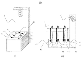
このとき、光源を指の真上に設置すると、光源を設置するための構造物により指の提示
位置が閉鎖的になり、利用者の心理的抵抗感が高まる。これを避けるために、指の側面上
方あるいは指先側の前方上方に光源を設置する。本実施例では光源3を指の提示位置の前
方上方に設置する。これにより指の上方の空間を開放的にすることができ、閉塞的な空間
に指を提示する際に利用者が感じる心理的抵抗感を軽減できる。
At this time, when the light source is installed right above the finger, the presentation position of the finger is closed by the structure for installing the light source, and the psychological resistance of the user is increased. In order to avoid this, a light source is installed on the upper side of the finger or on the upper front side of the fingertip. In this embodiment, the
もし、指の側面上方に設置した場合、光源から指に向けて照射された光が指の側面側の
広い領域を強く照らし、その結果、透過光に含まれる静脈パターンがその光により打ち消
され、静脈画像のコントラストが低下する。一方、指先側の前方に設置した場合は指先付
近の狭い領域のみが照らされるだけで留まり、コントラスト低下が生じにくい。本実施例
の光源の設置方法により、この問題をも解決することができる。
If installed on the side of the finger, the light emitted from the light source toward the finger strongly illuminates a wide area on the side of the finger, and as a result, the vein pattern contained in the transmitted light is canceled by the light, The contrast of the vein image is reduced. On the other hand, when it is installed in front of the fingertip side, only a narrow area near the fingertip is illuminated and the contrast is hardly lowered. This problem can also be solved by the light source installation method of this embodiment.
しかし、このように光源が指の前方に設置されていると、指の根元側ほど光が届きにく
くなる。鮮明な静脈パターンを獲得するためには、指に照射される光量を均一にし、輝度
むらの少ない画像を撮影することが重要である。従って、光源3を複数個設置し、照射す
る部位が指先に近い光源ほど光量を弱く、根元側に近いほど光量を強くすることが望まし
い。本実施例では複数個の光源をそれぞれ独立に制御することで、指に届く光量が均一に
なるようにする。あるいは、指先側を照射する光源の光量に対して根元側を照射する光源
の光量が強くなるように、予め光量を調節し、複数の光源の制御を同時に行ってもよい。
これにより制御を簡略化できる。光源3は縦方向に一列のみではなく、複数個の光源を面
状に配置してもよい。これにより提示位置の許容範囲を左右方向に広げることができる。
光源を面状の配置にした場合は、撮像画像を用いて指の提示位置を検知し、指の前方にあ
る光源のみを点灯するように制御してもよい。これにより認証装置の消費電力を抑えるこ
とが可能となる。
However, when the light source is installed in front of the finger in this way, it becomes difficult for light to reach the base side of the finger. In order to obtain a clear vein pattern, it is important to capture an image with less luminance unevenness by making the amount of light applied to the finger uniform. Therefore, it is desirable to install a plurality of
Thereby, control can be simplified. The
When the light source is arranged in a planar shape, it may be controlled to detect the presentation position of the finger using the captured image and turn on only the light source in front of the finger. As a result, the power consumption of the authentication device can be suppressed.
入力インターフェース2の表面には、指の提示位置を決めるためのガイドとして線21
乃至23が設けられている。利用者は、線21に指の高さを、線22に指の中心軸を、線
23に指先の位置を合わせることで指の提示位置を決定する。このガイドにより、認証時
に自分の指の位置を確認しながら提示できるため、提示位置の再現性が高くなる。あるい
は、線の代わりに該当位置に点を設けてもよい。
A
Thru 23 are provided. The user determines the finger presentation position by aligning the finger height with the
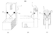
非接触の認証装置では、上述したように、指の位置ずれが起こったときに撮像部に光源
からの強い光が入り込み、鮮明な画像を獲得できなくなることが問題となる。本実施例で
は、提示された指に光が照射され、かつ、撮像部に対して悪影響を与えるほどの強い光が
撮像部に入らないように光源3の照射方向を調整する。具体的には、図3(a)で示すよ
うに、光源3を、撮像部4よりさらに左側を照射するような向きで設置する。
As described above, the non-contact authentication device has a problem that when the finger is displaced, strong light from the light source enters the imaging unit and a clear image cannot be obtained. In the present embodiment, the irradiation direction of the
以下、指の位置ずれにより、本来指を透過してから撮像部4に届くはずの光が直接入射
した場合にも十分な品質の画像を撮影できることを保証するための、光源3を設置する向
きの決定方法について述べる。
Hereinafter, the direction in which the
まず、撮像部4に強い光が入射しない光源の向きについて説明する。撮像部4に強い光
が届くと、撮像素子対してスミアノイズが発生する、またはレンズやフィルタなどの光学
部品で反射が起こり部品そのものの影が映り込む。特に部品の映り込みによるノイズは光
量が小さい場合にも発生しやすい。よって、撮像画像中の映り込みによるノイズの量を調
べることで、悪影響を与えるほどの光が撮像部に届いているか否かを確認することが可能
である。このノイズの影響度を定量的に求めるために以下のような実験を行った。
First, the direction of the light source in which strong light does not enter the
図3(a)はこの実験で使用した装置の部品の配置図である。光源には指向特性15度
、定格100mw/SrのLEDを用いた。また、光源3は、撮像平面と光源の照射方向のなす角αを0度から90度の範囲で可動できる構造になっている。
FIG. 3A is a layout diagram of parts of the apparatus used in this experiment. The light source used was an LED with a directional characteristic of 15 degrees and a rating of 100 mw / Sr. In addition, the
まず、光源3の光量をこのLEDの定格である100mw/Srに設定した。次に、αを0度から90度に変動させながら、撮像装置4にて撮像装置上方の空間を撮影した。本実験では、指の提示位置が大きくずれたときの光の影響を調べることが目的であるため、指の位置が最も大きくずれた状態、すなわち、装置上に指を提示しない状態で撮影を行った。その後、撮影した画像に対し、後述の特徴量抽出処理S109を適用した。この処理により抽出された特徴の量をノイズの量とした。このノイズが認証にどの程度の影響を与えるかを調べるために、上記装置で実際に指静脈画像を撮影し、撮像画像に特徴抽出処理を実施し得られた静脈パターンの量とノイズの量との割合を、ノイズの影響度とした。
First, the light quantity of the
図3(b)は光源3の設置方向αと光源3の光によって発生するノイズの影響度との関
係を示すグラフである。このグラフから、αの値が小さいときと、αが90に近いときは
静脈パターンに対するノイズの割合が少なく、それ以外ではノイズの割合が多くなること
がわかる。このノイズの割合が大きくなるほど、認証結果に悪影響を与える。一般に静脈
認証ではノイズの量が25%程度を超えると正しい認証を行うことができない。よって光
源3はノイズが25%以下に抑えられる角度に設置する。図(b)のグラフよりα=24
度以下、αが81度以上であればノイズを25%以内に抑えられることがわかる。よって
、図3(a)のような位置にカメラと光源を設置した場合は、αが24度以下またはαが
81度以上になるように光源を設置する。これにより指の提示位置がずれた場合でも光源
3からの悪影響を抑えることができ、十分な品質の画像を撮影することが可能となる。
FIG. 3B is a graph showing the relationship between the installation direction α of the
It can be seen that the noise can be suppressed to 25% or less when α is 81 degrees or less. Therefore, when the camera and the light source are installed at the position shown in FIG. 3A, the light source is installed so that α is 24 degrees or less or α is 81 degrees or more. Thereby, even when the presentation position of the finger is deviated, the adverse effect from the
次に、撮像部に悪影響を与えない角度のうち、提示された指に対して光が照射される光
源の向きについて述べる。αが81度以上の時は光源3からの光が撮像部よりも右側に照
射されるため、撮像部上方に提示される指に静脈画像を獲得できるほどの十分な量の光が
届かない。一方αが24度以下になるように光源の向きを調節すると、撮像部上方の空間
にも十分な量の光が届き、指静脈画像の獲得が可能となる。
Next, of the angles that do not adversely affect the imaging unit, the direction of the light source that emits light to the presented finger will be described. When α is 81 degrees or more, the light from the
以上のことから、図3(a)のような位置関係に光源と撮像部を設置した場合はα=2
4度以下になるように光源を設置することが望ましく、これにより、指1には光が照射さ
れ、かつ、撮像部には強い光が入らない入力インターフェースが実現できる。特に、αが
24度になるように光源の向きを調整すると、光源3から出力される光量に対して指に照
射される光量の割合が最も高くなるため、消費電力を抑えることができる。
From the above, α = 2 when the light source and the imaging unit are installed in the positional relationship as shown in FIG.
It is desirable to install the light source so that the angle is 4 degrees or less, thereby realizing an input interface in which the finger 1 is irradiated with light and strong light does not enter the imaging unit. In particular, when the direction of the light source is adjusted so that α is 24 degrees, the ratio of the amount of light irradiated to the finger with respect to the amount of light output from the
さらに別の表現によれば、光源からの光が、提示された指に入射してそこからの透過光
は撮像部に入射するが、光源からの直接光(の大部分)は撮像部に入射しないように光源
の向きを設定すれば、撮像部の入力が飽和することを防ぐことができる。
According to another expression, light from the light source is incident on the presented finger, and transmitted light from the finger is incident on the imaging unit, but direct light (most of the light) from the light source is incident on the imaging unit. If the direction of the light source is set so as not to occur, the input of the imaging unit can be prevented from being saturated.
以下、認証プログラム100で実施される処理手順の一実施例について図4を用いて説
明する。
Hereinafter, an example of a processing procedure performed by the
初めに、指の提示を検知する処理を行う(S101)。入力インターフェース2で静脈
画像を獲得するためには、指が光源3より低い位置に提示されている必要がある。指が適
切な高さに提示されたことを検知する方法として、後述のような、複数光源を指に照射し
、その照射位置に基づき高さを算出する方法や、光源3と同じ高さで撮像部に映り込むよ
うに設置した別の光源を常時わずかに点灯させておき、光が遮蔽された状態を検知する方
法などが利用できる。
First, processing for detecting presentation of a finger is performed (S101). In order to acquire a vein image with the
指の提示が検知されると、最も鮮明な画像が得られるように光源3の光量が調整される
(S103)。これには、画像の平均輝度値を常に監視し、その値に応じて光量をフィード
バック制御する手法、指静脈パターンの画像に対しパターンの鮮明度を判定する評価関数
を施し、その結果を最適化するような光量調整を実施する手法、などを用いることができ
る。
When the finger presentation is detected, the light amount of the
(S103). For this purpose, the average luminance value of the image is constantly monitored, the light amount is feedback-controlled according to that value, and an evaluation function that determines the sharpness of the pattern is applied to the finger vein pattern image, and the result is optimized. For example, a method for adjusting the amount of light can be used.
次に、指の輪郭を検出する(S104)。検出方法としては、画像のエッジを強調する手
法、エッジ部分を追跡する方法などがある。
Next, the contour of the finger is detected (S104). As a detection method, there are a method of enhancing an edge of an image, a method of tracking an edge portion, and the like.
輪郭検出後、平行方向または平面内の回転方向の向き補正を実施する(S106)。輪郭
情報から指の長手方向の向きを推定し、その角度が一定になるように画像を回転する方法
などがある。
次に、血管パターンの特徴抽出処理を実施する(S108)。この手法として、線分を強調
するエッジ強調フィルタやマッチドフィルタを用いる方法、線成分を追跡することで線パ
ターンを抽出する方法、画像の断面プロファイルにおける輝度値の局所的な窪み位置を抽
出する方法などを用いることができる。
After the contour detection, the direction correction in the parallel direction or the rotation direction in the plane is performed (S106). There is a method of estimating the direction of the finger in the longitudinal direction from the contour information and rotating the image so that the angle is constant.
Next, blood vessel pattern feature extraction processing is performed (S108). As this technique, a method using an edge emphasis filter or a matched filter for emphasizing a line segment, a method of extracting a line pattern by tracking a line component, and a method of extracting a local depression position of a luminance value in a cross-sectional profile of an image Etc. can be used.
その後、抽出あるいは強調した血管パターンから特徴量を抽出する(S109)。特徴
量として、画像そのものを特徴量とする方法、分岐点や端点を検出する方法などを用いる
ことができる。
Thereafter, feature quantities are extracted from the extracted or emphasized blood vessel pattern (S109). As the feature amount, a method of using the image itself as a feature amount, a method of detecting a branch point or an end point, and the like can be used.
最後に、生成した特徴量と事前に登録されている特徴量とを比較照合する。(S112
)。画像そのものを特徴量としている場合では、画像同士を重ね合わせ、画素値同士の比
較を実施して一致率を計算する。分岐点や端点を特徴量としている場合はそれらの位置、
個数、分岐線の角度、相対的な距離などの情報を比較することで一致率を算出する。ここ
で得られた一致率によって、同一パターンであるか別パターンであるかを判定する。判定
するための閾値は事前に統計的に算出しておくことが可能である。閾値よりも高い一致率
となった場合は登録者と判定し、低い場合は登録されていない指が提示されたとみなし認
証を拒否する。
Finally, the generated feature value is compared with the feature value registered in advance. (S112
). In the case where the image itself is used as a feature amount, the images are overlapped and the pixel values are compared to calculate the coincidence rate. If branching points and end points are used as features, their positions,
The coincidence rate is calculated by comparing information such as the number, branch line angle, and relative distance. Whether the patterns are the same pattern or different patterns is determined based on the matching rate obtained here. The threshold for determination can be statistically calculated in advance. If the coincidence rate is higher than the threshold, it is determined as a registrant, and if it is lower, it is considered that an unregistered finger has been presented and authentication is rejected.
登録者であると判定された場合は、ドアを開ける等の認証後の処理を行う(S114)
。
If it is determined that the user is a registered person, post-authentication processing such as opening a door is performed (S114).
.
図5は、指の位置決めのための送風手段を設けた非接触型指静脈認証装置の入力インタ
ーフェース2の一構成例である。図5(a)は入力インターフェースの概略図、図5(b)は
側面図である。
FIG. 5 is a configuration example of the
入力インターフェース2には、図5で示すように指提示位置の指先下方部に送風手段4
1が設置されている。指1の提示が検知されると、この送風手段41から、垂直上方に向
かって送風が開始される。利用者は風が指先に当たる位置に指をかざすことで、入力イン
ターフェースに直接触れることなく、指の提示位置を決定することができる。これにより
、高い再現性を持って指の静脈画像を撮影できるため認証精度が高くなる。また、指の提
示位置が触覚的に容易に分かるため利便性が向上する。
As shown in FIG. 5, the
1 is installed. When the presentation of the finger 1 is detected, blowing is started from the blowing
送風手段は指先の位置だけでなく、指の付け根側の下方部に設置してもよい。これによ
り指先と指付け根の2箇所の位置決めが可能になり、指1の回転を防ぐことができる。さ
らに、指を提示する高さを決めるための送風手段41を指の前方の壁面内に設置し、指先
に向けて送風を行ってもよい。位置決めのための送風手段を複数個設置すると、指の提示
位置の変動をさらに抑えることができるためより安定した認証を行うことができる。
The air blowing means may be installed not only at the position of the fingertip but also at the lower part on the base side of the finger. As a result, the two positions of the fingertip and the finger base can be positioned, and the rotation of the finger 1 can be prevented. Furthermore, the ventilation means 41 for determining the height which shows a finger may be installed in the wall surface ahead of a finger, and you may ventilate toward a fingertip. If a plurality of air blowing means for positioning are installed, fluctuations in the finger presentation position can be further suppressed, so that more stable authentication can be performed.
図6は、指の位置決め用の送風手段を設けた非接触型指静脈認証装置の入力インターフ
ェース2の一構成例である。 図6(a)は入力インターフェースの概略図、図6(b)
は入力インターフェースの側面図である。
FIG. 6 is a configuration example of the
FIG. 4 is a side view of the input interface.
図6に示すように入力インターフェース2には指1の適切な提示位置を囲うように送風
手段41が設置されている。指1の提示が検知されると、この送風手段41から、上方に
向かって送風を行う。指1の提示位置が所定の位置からずれた場合この風が指1に当たる
。利用者は風を避けるように指を移動させる。全ての送風手段からの風が当たらないよう
に指を移動させることで、正しい提示位置へ自然に誘導することができる。このように、
風を避けるという自然な動作で、指1の左右方向の位置ずれと水平面内での回転を防ぐこ
とができる。
As shown in FIG. 6, the
The natural movement of avoiding the wind can prevent the finger 1 from shifting in the horizontal direction and rotating in the horizontal plane.
図7は指の位置決めのために可視光源を設けた非接触型指静脈認証装置の入力インター
フェース2の一構成例である。図7(a)に入力インターフェース2の概略図、図7(b)
に側面図を示す。
FIG. 7 is a configuration example of the
Shows a side view.
指前方の壁面内には指の提示位置を指示するための可視光源61が設置されている。利
用者は可視光源61から照射される可視光が爪の中央や関節など、所定の指の部位に当た
る位置に指を提示することで、指の位置決めを行う。このように、可視光を利用して位置
決めを行うことで、入力インターフェース2に直接触れることなく、毎回安定した位置に
指をかざすことができる。これにより認証精度が向上する。本実施例において可視光源6
1と赤外光源3は複数波長を発光できるLEDなどを利用して1つの光源とすることも可
能である。
A
1 and the infrared
図8は指の位置決めのために複数の可視光源を設置した非接触型指静脈認証装置の入力
インターフェース2の一構成例である。図8(a)は入力インターフェース2の概略図、
図8(b)は側面図、図8(c)は上面図である。
FIG. 8 is a configuration example of the
FIG. 8B is a side view, and FIG. 8C is a top view.
図8で示すように、指の前方上方に2個の可視光源61が設置されている。それぞれの
光源から出る可視光が指先の提示位置で交わるように、内側に向けて照射される。利用者
は二つの光源からの光が爪や関節などの所定の部位に重なって当たるように指をかざすこ
とで指の提示位置を決定する。指の提示位置のガイドとして複数の光源からの光を利用す
ると、指1の提示位置が左右方向に加え上下方向についても一意に決めることができる。
これにより、指の位置ずれをより少なくすることができ認証精度が向上する。
As shown in FIG. 8, two
Thereby, the positional deviation of the finger can be further reduced, and the authentication accuracy is improved.
図9は、複数の赤外光源を利用して指の高さを算出する指静脈認証装置の入力インター
フェース2の一構成例である。図9(a)は入力インターフェースの概略図、図9(b)
は側面図である。また、図9(c)(d)(e)は指1の上下方向の位置が変化したとき
の赤外光源63,64からの光の照射される位置の変化を示す図である。
FIG. 9 is a configuration example of the
Is a side view. FIGS. 9C, 9D, and 9E are diagrams showing changes in the position irradiated with light from the infrared
図9(a)で示すように、入力インターフェース2には指先の提示位置を検知するため
に、指先側の下方部に赤外光源63、指の付け根側の下方に赤外光64が設置されている
。2つの光源63、64は、図9(b)で示すように、それぞれの光源からの光が指先の
適切な提示位置で交わるような向きに設置されている。利用者が入力インターフェース上
に指をかざすと、2つの光源63、64は指先の掌側を強く照射する。このとき撮像部4
で指を撮影すると、照射された部分が点となって現れる。指1が正しい位置に提示されて
いた場合、図9(c)で示すように、二つの光源からの光は、掌側表面の同じ位置に照射
されるため2つの点が重なる。指1が正しい提示位置よりも高い位置に提示された場合は
、図9(d)で示すように、光源64からの光は、光源63からの光に対して指先側に照
射される。逆に、指1が低い位置に提示された場合、図9(e)で示すように、光源64
の光は、光源63の光と比べて指の付け根側に照射される。よって、2つの光が反射する
点の位置を画像処理によって検出することで、指の提示されている高さを自動的に算出す
ることができる。
As shown in FIG. 9A, in the
If you shoot your finger with, the irradiated part will appear as a point. When the finger 1 is presented at the correct position, as shown in FIG. 9C, the light from the two light sources irradiates the same position on the palm side surface, so the two points overlap. When the finger 1 is presented at a position higher than the correct presentation position, the light from the light source 64 is emitted toward the fingertip side with respect to the light from the
Is irradiated on the base side of the finger as compared with the light of the
このとき、指表面の点が2つの光源のどちらから発せられたものなのかを区別する必要
がある。これは、光源63と光源64から異なる大きさや形状の光を照射する方法や、光
源63と光源64を点灯させるタイミングをずらす方法などで実現できる。
At this time, it is necessary to distinguish from which of the two light sources the point on the finger surface is emitted. This can be realized by a method of irradiating light of different sizes and shapes from the
このように複数の光源を利用することで指の提示位置を知ることができる。これにより
指が正しい位置に提示されたことを確認して認証を行うことができる。また、算出された
指の提示位置の情報を用いて利用者に対してガイドを行ってもよい。
Thus, the presentation position of the finger can be known by using a plurality of light sources. Thus, authentication can be performed after confirming that the finger is presented at the correct position. Moreover, you may guide a user using the information of the calculated presentation position of the finger.
ガイドの方法は、上下どちらに移動させればよいかを示すLEDを入力インターフェース
2に設置する方法や、表示部15に移動させる方向を表示する方法などがある。これによ
り利用者が再現良く指の提示を行えるようになり認証制度が向上する。
As a guide method, there are a method of installing an LED indicating whether to move up or down on the
図10は指の位置と回転を検知するための撮像部を設置した非接触型指静脈認証装置の
入力インターフェース2の一構成例である。図10のように指の前面と側面に設置された
壁面内には、指1を正面から撮影するための撮像部121−1と指1の側面を撮影するた
めの撮像部121−2、が設置されている。
FIG. 10 shows a configuration example of the
本実施例に示す認証装置では、利用者が入力インターフェース上に指1を提示する際、
指の提示位置の変動や回転が起こる場合がある。その中で撮像部4の撮像平面内の位置ず
れと回転については、輪郭情報を用いた回転補正処理を行うことで、補正することができ
る。しかし、入力インターフェース上に指をかざす際には、撮像部4の撮像平面内の回転
だけではなく、指の長軸、短軸に対する軸回転や指の上下、左右、前後方向の位置ずれが
起こりうる。そこで、利用者が再現よく指の提示を行えるようにするために、撮像部4に
加えて撮像部121−1、121−2を設置する。利用者が指を提示すると、撮像部12
1−1と撮像部121−2によって指の正面の画像300−1と指の側面画像300−2
が撮影される。このときに得られる複数の画像を利用して指1の3次元的な位置ずれや回
転の検知を行い、それを基に利用者に対してガイドを行う。以下、指の位置、回転の検知
方法の一例を示す。
In the authentication apparatus shown in the present embodiment, when the user presents the finger 1 on the input interface,
The finger presentation position may change or rotate. Among them, the positional deviation and rotation in the imaging plane of the
1-1 and imaging unit 121-2, finger front image 300-1 and finger side image 300-2.
Is filmed. A plurality of images obtained at this time are used to detect a three-dimensional positional shift and rotation of the finger 1, and the user is guided based on the detection. Hereinafter, an example of a finger position / rotation detection method will be described.
まず、指の正面からの撮像画像300−1を用いて、指1の左右、上下方向の位置と、
指の長軸に対する軸回転を検出する。指の上下、左右方向の位置を求めるために、撮像画
像300−1から指の領域の抽出を行う。これには画像のエッジを強調する手法、エッジ
部分を追跡する方法などを用いることができる。求めた指領域の中心位置を算出し、指の
提示位置とする。次に、指の回転を検出する。これは、撮像画像300−1に映る手の向
きを検出する方法、爪の向きを検出する方法を用いることができる。爪領域は光源3から
の光が当たっていてより鮮明に撮影できるため、本実施例では、爪の向きを検出する方法
を用いる。まず、上記の手順で求めた指領域の中から、爪領域の検出を行う。これには、
エッジを強調する方法や、指先に光を当ててその反射率の違いから検出する方法が利用で
きる。次に、求めた爪領域の回転を検出する。撮影画像300−1のように指を正面から
撮影した場合、爪領域は横長の楕円状の形に撮影される。よって、爪領域の長軸方向の向
きを推定し、長軸と撮像画像内の水平方向に対する角度を計算することで爪の回転量を算
出できる。これにより指の長軸に対する軸回転を検出することができる。
First, using the captured image 300-1 from the front of the finger,
Detects shaft rotation relative to the long axis of the finger. In order to obtain the vertical and horizontal positions of the finger, the finger region is extracted from the captured image 300-1. For this, a method for enhancing the edge of an image, a method for tracking an edge portion, or the like can be used. The calculated center position of the finger area is calculated and used as the finger presentation position. Next, the rotation of the finger is detected. For this, a method of detecting the orientation of the hand shown in the captured image 300-1 or a method of detecting the orientation of the nail can be used. Since the nail area is exposed to light from the
A method of enhancing an edge or a method of detecting light from a difference in reflectance by shining light on a fingertip can be used. Next, the rotation of the obtained nail region is detected. When a finger is photographed from the front as in the photographed image 300-1, the nail region is photographed in a horizontally long elliptical shape. Therefore, the amount of nail rotation can be calculated by estimating the direction of the long axis direction of the nail region and calculating the angle between the long axis and the horizontal direction in the captured image. Thereby, the shaft rotation with respect to the long axis of the finger can be detected.
撮像画像300−2に対しても同様の処理を行い、指の短軸の軸回転、前後方向の位置
の検出を行う。撮像画像300−2から指の輪郭を抽出し、抽出した指領域の中心位置を
指の位置として求める。さらに、指領域の長手方向の向きを調べることで、指の短軸に対
する軸回転を検知する。
The same process is performed on the captured image 300-2, and the short axis of the finger is rotated and the position in the front-rear direction is detected. The contour of the finger is extracted from the captured image 300-2, and the center position of the extracted finger region is obtained as the finger position. Furthermore, the rotation of the finger relative to the short axis is detected by examining the orientation of the finger region in the longitudinal direction.
このようにして求めた指の位置、回転の情報を基に指が適切な位置に提示されているか
を判定する。これは、登録時の指の位置や回転と、認証時の提示位置、回転を比較するこ
とで行う。登録時と認証時の位置ずれや回転角の違いが、事前に定義しておいた許容範囲
よりも大きい場合は、指を提示しなおすように利用者に対してガイドを行う。
It is determined whether the finger is presented at an appropriate position based on the finger position and rotation information thus obtained. This is done by comparing the finger position and rotation during registration with the presentation position and rotation during authentication. When the difference between the positional deviation and the rotation angle at the time of registration and at the time of authentication is larger than the permissible range defined in advance, the user is guided to re-present the finger.
なお、撮像部121−1、121−2には広角レンズを利用することで、指と撮像部の
距離が近い場合でも広範囲での位置ずれを捕らえることが可能になる。
In addition, by using a wide-angle lens for the imaging units 121-1 and 121-2, it is possible to catch a wide range of position shift even when the distance between the finger and the imaging unit is short.
図11は指先の静脈で認証を行う小型の非接触指静脈認証装置の入力インターフェース
2の一構成例である。図11(a)は入力インターフェースの概略図であり、図11(b
)は入力インターフェースの側面図である。
FIG. 11 shows a configuration example of the
) Is a side view of the input interface.
本実施例では、指先から第一関節付近の掌側の静脈を非接触に提示し、認証を行う。指
全体の静脈を利用して認証を行う場合、指が曲がることによって撮像画像が変化し認証精
度が低下する場合があるが、指先部分を利用すると、そのような指形状の変化の影響を小
さくすることができ、安定した認証を行うことができる。また、撮影する範囲が狭いので
入力インターフェースの小型化が可能になる。さらに照射する範囲も狭くなるため、光源
3の数を減らすことができる。
In this embodiment, the palm-side vein near the first joint from the fingertip is presented in a non-contact manner and authentication is performed. When authentication is performed using the veins of the entire finger, the captured image may change due to bending of the finger and authentication accuracy may be reduced. However, if the fingertip part is used, the effect of such finger shape changes is reduced. And stable authentication can be performed. In addition, since the shooting range is narrow, the input interface can be downsized. Furthermore, since the irradiation range is also narrowed, the number of
図11で示すように、入力インターフェース側面には外光を遮断するための遮光板11
1が設置されている。遮光板は指先から第一関節部分までを遮光できる大きさのもので十
分であるため、別の指や指の付け根が接触しにくく、利用者にとって使いやすい認証装置
が実現できる。
As shown in FIG. 11, a light shielding plate 11 for blocking outside light is provided on the side of the input interface.
1 is installed. Since the light shielding plate having a size that can shield light from the fingertip to the first joint portion is sufficient, it is difficult for another finger or the base of the finger to come into contact, and an authentication device that is easy to use for the user can be realized.
装置の前方上部の壁面内には、指の提示位置を指示するための可視光源61と静脈画像
を撮影するための赤外光源3が設置されている。これらの光源は複数波長を発光できるLE
Dなどを利用して1つの光源としてもよい。これによりさらに入力インターフェースが小
型化できる。利用者は図11(b)のように、可視光源61の光が爪の中央に当たるよう
に指を提示し、認証を行う。このとき光源3が指の爪皮部分を照射するように設置されて
いると、より鮮明な画像を撮影することができる。
A
D or the like may be used as one light source. This further reduces the size of the input interface. As shown in FIG. 11B, the user presents a finger so that the light from the visible
図12は本実施例の認証装置を折りたたみ式の携帯電話機に適用した例である。図12
(a)は携帯電話機を上面から見た図、図12(b)は側面図である。
FIG. 12 shows an example in which the authentication apparatus of this embodiment is applied to a folding mobile phone. FIG.
(A) is the figure which looked at the mobile telephone from the upper surface, FIG.12 (b) is a side view.
携帯電話機のボタン設置面と同じ面に撮像装置4が設置され、それと対向する位置に光
源3が設置されている。本認証装置が備わっている携帯電話端末は、端末を閉じると、自
動でロックがかけられる。ロック状態では、電話帳やメール、画像等全てのデータにロッ
クがかかり、電源のON、OFF以外の操作ができなくなっている。携帯電話機を利用する場
合、利用者は、図のように指を提示する。このとき携帯電話機のボタンに指先の位置と指
の中心軸を合わせるようにして指を提示すると、図2で示した位置決め用の線22、23
と同様の効果を得ることができる。また、携帯電話機のディスプレイ125には図12で
示すような線を表示する。利用者はこの位置に指の高さを合わせることで指の提示する高
さを決めることができる。指が提示されると、光源3から光が照射され、撮像部4で静脈
パターンの画像が撮影される。この画像を用いて、携帯電話機の正しい利用者であるか否
かを判定する。正しく認証された場合、携帯電話のロックが解除される。この認証機能は
、メール機能のロック解除、ダイヤル発信制限の解除、ICカード機能のロック等にも利用
できる。
The
The same effect can be obtained. A line as shown in FIG. 12 is displayed on the
本認証装置は、携帯電話機やノートPC、ATM、PDAなどL字型の構造になっているあらゆ
る機器に搭載することが可能である。
This authentication device can be installed in any device that has an L-shaped structure, such as a mobile phone, notebook PC, ATM, or PDA.
1・・・指、2・・・入力インターフェース、3・・・光源、4・・・撮像部、10・
・・認証処理部、11・・・CPU、12・・・メモリ、13・・・インターフェース、
14・・・記憶装置、15・・・表示部、16・・・入力部、17・・・スピーカ、18
・・・画像入力手段、100・・・認証プログラム、200・・・登録データ、250・
・・認証データ、21・・・位置決め用の線、22・・・位置決め用の線、23・・・位
置決め用の線、41・・・送風手段、61・・・可視光源、111・・・遮光板、121
−1・・・撮像部、121−2・・・撮像部、63・・・光源、64・・・光源、125
・・ディスプレイ。
DESCRIPTION OF SYMBOLS 1 ... Finger, 2 ... Input interface, 3 ... Light source, 4 ... Imaging part, 10 *
..Authentication processing unit, 11 ... CPU, 12 ... memory, 13 ... interface,
14 ... Storage device, 15 ... Display unit, 16 ... Input unit, 17 ... Speaker, 18
... Image input means, 100 ... Authentication program, 200 ... Registration data, 250
..Authentication data, 21... Positioning wire, 22 .. positioning wire, 23 .. positioning wire, 41 .. blowing means, 61 .. visible light source, 111. Shading plate, 121
-1 ... Imaging unit, 121-2 ... Imaging unit, 63 ... Light source, 64 ... Light source, 125
··display.
Claims (8)
前記指の提示位置は前記撮像部よりも上方に配置され、
前記複数の光源は、前記指の提示位置よりも奥、かつ該指の提示位置よりも高い位置に配置され、前記制御手段は、前記複数の光源の各々による前記指への照射部位に応じて、夫々異なる光量に制御されることを特徴とする個人認証装置。 An input interface including a plurality of light sources that emit infrared light, an imaging unit that captures an image of a blood vessel of a finger with light from the light source, and an image calculation unit that performs feature extraction and feature matching from the captured image And a personal authentication device having positioning means for presenting the finger, and control means for controlling at least the plurality of light sources,
The presenting position of the finger is arranged above the imaging unit,
The plurality of light sources are disposed at a position deeper than the finger presentation position and higher than the finger presentation position, and the control means is configured to respond to an irradiation site on the finger by each of the plurality of light sources. The personal authentication device is characterized in that each is controlled to have a different light quantity.
前記指を提示する位置決め手段と、前記複数の光源を少なくとも制御する制御手段とを有する個人認証装置において、
前記指の提示位置は前記撮像部よりも上方に配置され、
前記複数の光源は、前記指の提示位置よりも奥、かつ該指の提示位置よりも高い位置に配置され、前記複数の光源は、光源の各々による指への照射部位のうち、当該照射部位が指先に近いほど光量を弱くなるように前記制御手段により制御されることを特徴とする個人認証装置。 An input interface including a plurality of light sources that emit infrared light, an imaging unit that captures an image of a blood vessel of a finger with light from the light source, and an image calculation unit that performs feature extraction and feature matching from the captured image When,
In a personal authentication device having positioning means for presenting the finger and control means for controlling at least the plurality of light sources,
The presenting position of the finger is arranged above the imaging unit,
The plurality of light sources are arranged at a position deeper than the finger presentation position and higher than the finger presentation position, and the plurality of light sources are the irradiation parts of the irradiation parts to the finger by each of the light sources. The personal authentication device is controlled by the control means so that the light intensity becomes weaker as the distance from the fingertip increases.
Priority Applications (1)
| Application Number | Priority Date | Filing Date | Title |
|---|---|---|---|
| JP2008287286A JP4604117B2 (en) | 2008-11-10 | 2008-11-10 | Personal authentication apparatus and method |
Applications Claiming Priority (1)
| Application Number | Priority Date | Filing Date | Title |
|---|---|---|---|
| JP2008287286A JP4604117B2 (en) | 2008-11-10 | 2008-11-10 | Personal authentication apparatus and method |
Related Parent Applications (1)
| Application Number | Title | Priority Date | Filing Date |
|---|---|---|---|
| JP2006242266A Division JP4640295B2 (en) | 2006-09-07 | 2006-09-07 | Personal authentication apparatus and method |
Publications (2)
| Publication Number | Publication Date |
|---|---|
| JP2009076092A JP2009076092A (en) | 2009-04-09 |
| JP4604117B2 true JP4604117B2 (en) | 2010-12-22 |
Family
ID=40610928
Family Applications (1)
| Application Number | Title | Priority Date | Filing Date |
|---|---|---|---|
| JP2008287286A Active JP4604117B2 (en) | 2008-11-10 | 2008-11-10 | Personal authentication apparatus and method |
Country Status (1)
| Country | Link |
|---|---|
| JP (1) | JP4604117B2 (en) |
Families Citing this family (3)
| Publication number | Priority date | Publication date | Assignee | Title |
|---|---|---|---|---|
| CN104615993B (en) * | 2015-02-12 | 2016-08-24 | 张丽琴 | The certification device and method that a kind of finger vena identification combines with face hand vein recognition |
| CN106960194A (en) * | 2017-03-24 | 2017-07-18 | 徐晨 | A kind of vein identification device |
| CN111123986A (en) * | 2019-12-25 | 2020-05-08 | 四川云盾光电科技有限公司 | Control device for controlling two-degree-of-freedom turntable based on gestures |
Citations (3)
| Publication number | Priority date | Publication date | Assignee | Title |
|---|---|---|---|---|
| JP2001167255A (en) * | 1999-12-13 | 2001-06-22 | Masahiko Okuno | Device and method for non-contact fingerprint identification |
| JP2004164652A (en) * | 2003-11-25 | 2004-06-10 | Hitachi Ltd | Individual authentication device |
| JP2006106978A (en) * | 2004-10-01 | 2006-04-20 | Mitsubishi Electric Corp | Fingerprint image pickup unit |
-
2008
- 2008-11-10 JP JP2008287286A patent/JP4604117B2/en active Active
Patent Citations (3)
| Publication number | Priority date | Publication date | Assignee | Title |
|---|---|---|---|---|
| JP2001167255A (en) * | 1999-12-13 | 2001-06-22 | Masahiko Okuno | Device and method for non-contact fingerprint identification |
| JP2004164652A (en) * | 2003-11-25 | 2004-06-10 | Hitachi Ltd | Individual authentication device |
| JP2006106978A (en) * | 2004-10-01 | 2006-04-20 | Mitsubishi Electric Corp | Fingerprint image pickup unit |
Also Published As
| Publication number | Publication date |
|---|---|
| JP2009076092A (en) | 2009-04-09 |
Similar Documents
| Publication | Publication Date | Title |
|---|---|---|
| JP4640295B2 (en) | Personal authentication apparatus and method | |
| KR100927757B1 (en) | Information terminal | |
| KR100919339B1 (en) | Personal identification apparatus | |
| US8811689B2 (en) | Finger vein authentication device | |
| US8816817B2 (en) | Authentication apparatus | |
| JP5268293B2 (en) | Mobile terminal with personal authentication function | |
| JP5982311B2 (en) | Blood vessel imaging device | |
| JP4604117B2 (en) | Personal authentication apparatus and method | |
| JP5182341B2 (en) | Personal authentication apparatus and method | |
| JP6759065B2 (en) | Blood vessel imaging device and personal authentication system | |
| JP2009211730A (en) | Information terminal | |
| KR100895924B1 (en) | Vein authentication device | |
| KR100852829B1 (en) | Image processing apparatus, personal authentication method, and image processing method | |
| KR100852828B1 (en) | Vein authentication device |
Legal Events
| Date | Code | Title | Description |
|---|---|---|---|
| A131 | Notification of reasons for refusal |
Free format text: JAPANESE INTERMEDIATE CODE: A131 Effective date: 20100615 |
|
| A521 | Request for written amendment filed |
Free format text: JAPANESE INTERMEDIATE CODE: A523 Effective date: 20100809 |
|
| TRDD | Decision of grant or rejection written | ||
| A01 | Written decision to grant a patent or to grant a registration (utility model) |
Free format text: JAPANESE INTERMEDIATE CODE: A01 Effective date: 20100921 |
|
| A01 | Written decision to grant a patent or to grant a registration (utility model) |
Free format text: JAPANESE INTERMEDIATE CODE: A01 |
|
| A61 | First payment of annual fees (during grant procedure) |
Free format text: JAPANESE INTERMEDIATE CODE: A61 Effective date: 20101004 |
|
| FPAY | Renewal fee payment (event date is renewal date of database) |
Free format text: PAYMENT UNTIL: 20131008 Year of fee payment: 3 |
|
| R151 | Written notification of patent or utility model registration |
Ref document number: 4604117 Country of ref document: JP Free format text: JAPANESE INTERMEDIATE CODE: R151 |
|
| FPAY | Renewal fee payment (event date is renewal date of database) |
Free format text: PAYMENT UNTIL: 20131008 Year of fee payment: 3 |