JP4595967B2 - Reciprocating electric razor blade - Google Patents

Reciprocating electric razor blade Download PDF

Info

Publication number
JP4595967B2
JP4595967B2 JP2007183623A JP2007183623A JP4595967B2 JP 4595967 B2 JP4595967 B2 JP 4595967B2 JP 2007183623 A JP2007183623 A JP 2007183623A JP 2007183623 A JP2007183623 A JP 2007183623A JP 4595967 B2 JP4595967 B2 JP 4595967B2
Authority
JP
Japan
Prior art keywords
blade
frame
guide frame
outer blade
reciprocating electric
Prior art date
Legal status (The legal status is an assumption and is not a legal conclusion. Google has not performed a legal analysis and makes no representation as to the accuracy of the status listed.)
Active
Application number
JP2007183623A
Other languages
Japanese (ja)
Other versions
JP2009018056A (en
Inventor
宏明 清水
俊介 小森
武志 柴
重左エ門 岩崎
Current Assignee (The listed assignees may be inaccurate. Google has not performed a legal analysis and makes no representation or warranty as to the accuracy of the list.)
Panasonic Corp
Panasonic Electric Works Co Ltd
Original Assignee
Panasonic Corp
Matsushita Electric Works Ltd
Priority date (The priority date is an assumption and is not a legal conclusion. Google has not performed a legal analysis and makes no representation as to the accuracy of the date listed.)
Filing date
Publication date
Priority to JP2007183623A priority Critical patent/JP4595967B2/en
Application filed by Panasonic Corp, Matsushita Electric Works Ltd filed Critical Panasonic Corp
Priority to PCT/JP2008/062092 priority patent/WO2009008332A1/en
Priority to EP08777844A priority patent/EP2172316B1/en
Priority to RU2010100830/02A priority patent/RU2413604C1/en
Priority to CN2008800239091A priority patent/CN101687326B/en
Priority to US12/663,401 priority patent/US9199383B2/en
Priority to AT08777844T priority patent/ATE554890T1/en
Publication of JP2009018056A publication Critical patent/JP2009018056A/en
Application granted granted Critical
Publication of JP4595967B2 publication Critical patent/JP4595967B2/en
Active legal-status Critical Current
Anticipated expiration legal-status Critical

Links

Images

Classifications

    • BPERFORMING OPERATIONS; TRANSPORTING
    • B26HAND CUTTING TOOLS; CUTTING; SEVERING
    • B26BHAND-HELD CUTTING TOOLS NOT OTHERWISE PROVIDED FOR
    • B26B19/00Clippers or shavers operating with a plurality of cutting edges, e.g. hair clippers, dry shavers
    • B26B19/02Clippers or shavers operating with a plurality of cutting edges, e.g. hair clippers, dry shavers of the reciprocating-cutter type
    • B26B19/04Cutting heads therefor; Cutters therefor; Securing equipment thereof

Landscapes

  • Life Sciences & Earth Sciences (AREA)
  • Forests & Forestry (AREA)
  • Engineering & Computer Science (AREA)
  • Mechanical Engineering (AREA)
  • Dry Shavers And Clippers (AREA)

Abstract

A blade of a reciprocating electric shaver includes a newly provided guide frame (8) freely detachably held on a holding frame (7) provided on a shaver body, in which, in the guide frame (8), there are provided: coupling portions (9) to which an outer edge frame (2) that fixes an outer edge (1) thereto is coupled; and spring receiving portions (10) which support lower ends of inner edge push-up springs (5).

Description

本発明は、往復式電気かみそりの刃に関し、詳しくは外刃と外刃枠との結合を内刃ブロックとは独立して行なうための技術に関するものである。   The present invention relates to a reciprocating electric razor blade, and more particularly to a technique for coupling an outer blade and an outer blade frame independently of an inner blade block.

従来から、往復式電気かみそりの粗剃り用スリット刃は、例えば図11に示すように、外刃1Aと、外刃1Aを固定する外刃枠2Aと、外刃1Aの下面に配置される内刃3Aと、内刃3Aを駆動側に連結する内刃継手4Aと、内刃3Aを外刃1Aの内面に向けて押圧する内刃押上バネ5Aとを備え、内刃押上バネ5Aの下端を外刃枠2Aに設けたバネ受け部10Aにて支持し、内刃継手4Aを内刃押上バネ5Aの上端にて支持した状態で、外刃1Aを外刃枠2Aに対してヒートシール固定することで、スリット刃ブロック18を組み立てる構造が知られている(例えば、特許文献1参照)。   Conventionally, as shown in FIG. 11, for example, as shown in FIG. 11, a reciprocating electric razor rough shaving slit blade has an outer blade 1A, an outer blade frame 2A for fixing the outer blade 1A, and an inner surface disposed on the lower surface of the outer blade 1A. A blade 3A, an inner blade joint 4A that connects the inner blade 3A to the drive side, and an inner blade push-up spring 5A that presses the inner blade 3A toward the inner surface of the outer blade 1A, and a lower end of the inner blade push-up spring 5A are provided. The outer blade 1A is heat-sealed and fixed to the outer blade frame 2A while being supported by the spring receiving portion 10A provided on the outer blade frame 2A and the inner blade joint 4A supported by the upper end of the inner blade push-up spring 5A. Thus, a structure for assembling the slit blade block 18 is known (see, for example, Patent Document 1).

ところが上記特許文献1に見られる従来例においては、外刃1Aを外刃枠2Aに固定する際に、内刃押上バネ5Aのバネ付勢力Fに抗して外刃1Aを外刃枠2Aにヒートシール固定しなければならず、このため、剛性の高い外刃1Aのみ組立が可能となり、剛性の低い外刃1Aではバネ付勢力で変形して組立がうまくできないという不具合があった。
特開平11−42378号公報
However, in the conventional example shown in Patent Document 1, when the outer blade 1A is fixed to the outer blade frame 2A, the outer blade 1A is against the outer blade frame 2A against the spring biasing force F of the inner blade push-up spring 5A. Therefore, only the outer blade 1A having high rigidity can be assembled, and the outer blade 1A having low rigidity is deformed by a spring biasing force and cannot be assembled successfully.
Japanese Patent Laid-Open No. 11-42378

本発明は上記の従来の問題点に鑑みて発明したものであって、剛性の低い外刃であっても保持枠との組立を可能にするための新規なガイド枠を用いた往復式電気かみそりの刃を提供することを課題とするものである。   The present invention has been invented in view of the above-described conventional problems, and is a reciprocating electric shaver using a novel guide frame for enabling assembly with a holding frame even with an outer blade having low rigidity. It is an object to provide a blade.

前記課題を解決するために本発明にあっては、外刃1と、外刃1を固定する外刃枠2と、外刃1の下面に配置される内刃3と、内刃3を駆動側に連結する内刃継手4と、内刃3を外刃1の内面に向けて押圧する内刃押上バネ5とを備えた往復式電気かみそりの刃において、かみそり本体に設けた保持枠7に着脱自在に保持されるガイド枠8を備え、ガイド枠8に上記外刃1を固定した外刃枠2が結合する結合部9と、上記内刃押上バネ5の下端を支持するバネ受け部10とを設けたことを特徴としている。   In order to solve the above problems, in the present invention, the outer blade 1, the outer blade frame 2 for fixing the outer blade 1, the inner blade 3 disposed on the lower surface of the outer blade 1, and the inner blade 3 are driven. In a reciprocating electric razor blade provided with an inner blade joint 4 connected to the side and an inner blade push-up spring 5 for pressing the inner blade 3 toward the inner surface of the outer blade 1, a holding frame 7 provided on the razor body A guide frame 8 that is detachably held, a coupling portion 9 that couples the outer blade frame 2 that fixes the outer blade 1 to the guide frame 8, and a spring receiving portion 10 that supports the lower end of the inner blade push-up spring 5. It is characterized by providing.

このような構成とすることで、従来にはない新規なガイド枠8の結合部9に対して外刃1を固定した外刃枠2を結合させる一方で、ガイド枠8のバネ受け部10により内刃押上バネ5の下端を支持することによって、外刃1と外刃枠2とからなる外刃ブロック6Aと、内刃3と内刃継手4と内刃押上バネ5とからなる内刃ブロック6Bとをガイド枠8を利用して簡単に組み立てることができる。しかも、外刃ブロック6Aの組み立てを内刃ブロック6Bの内刃押上バネ5からのバネ付勢力が加わらない状態で行なうことができるので、剛性の低い外刃1であっても変形させることなく外刃枠2との結合ができ、外刃ブロック6Aの組立が容易となる。   With such a configuration, the outer blade frame 2 that fixes the outer blade 1 is coupled to the coupling portion 9 of the new guide frame 8 that is not conventionally provided, while the spring receiving portion 10 of the guide frame 8 is coupled. By supporting the lower end of the inner blade push-up spring 5, an outer blade block 6A composed of the outer blade 1 and the outer blade frame 2, and an inner blade block composed of the inner blade 3, the inner blade joint 4, and the inner blade push-up spring 5. 6B can be easily assembled using the guide frame 8. Moreover, since the outer blade block 6A can be assembled without applying the spring biasing force from the inner blade push-up spring 5 of the inner blade block 6B, the outer blade 1 having low rigidity can be assembled without being deformed. The blade frame 2 can be coupled and the outer blade block 6A can be easily assembled.

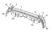
また、上記内刃3の往復駆動方向に沿う外刃枠2の長手方向A両端の上部に、外刃1の表面よりも突出する押さえ部11を夫々設け、押さえ部11を介して外刃枠2を押さえることで、外刃1を固定した外刃枠2をガイド枠8の結合部9に結合可能とするのが好ましく、この場合、外刃1を直接押すことなく、外刃1を外刃枠2に結合可能となるので、外刃1が変形することなく、組立がしやすくなる。   In addition, holding parts 11 that protrude from the surface of the outer blade 1 are provided at the upper ends of both ends in the longitudinal direction A of the outer blade frame 2 along the reciprocating drive direction of the inner blade 3, and the outer blade frame is interposed via the holding part 11. It is preferable that the outer cutter frame 2 with the outer cutter 1 fixed can be coupled to the coupling portion 9 of the guide frame 8 by pressing the outer cutter 1. In this case, the outer cutter 1 can be removed without pressing the outer cutter 1 directly. Since it becomes possible to couple to the blade frame 2, the outer blade 1 is not deformed and can be easily assembled.

また、上記内刃3の往復駆動方向に沿うガイド枠8の長手方向A両端に結合部9を夫々配置して、外刃枠2の長手方向A両端を結合させるのが好ましく、この場合、ガイド枠8の長手方向Aと直交する前後方向Bを薄型化できる。   Moreover, it is preferable to arrange | position the coupling | bond part 9 to the longitudinal direction A both ends of the guide frame 8 along the reciprocating drive direction of the said inner blade 3, respectively, and to couple | bond the longitudinal direction A both ends of the outer blade frame 2, In this case, a guide The longitudinal direction B perpendicular to the longitudinal direction A of the frame 8 can be reduced in thickness.

また、上記ガイド枠8は、長手方向A両端に位置する一対の枠部12と、一対の枠部12を互いに連結する連結部13とが一体に形成され、各枠部12に結合部9とバネ受け部10とを夫々設けるのが好ましく、この場合、一対の枠部12と連結部13との一体化によりガイド枠8の強度が向上し、これに伴い外刃枠2との結合強度が高まり、組立の信頼性が向上する。   The guide frame 8 is formed integrally with a pair of frame portions 12 positioned at both ends in the longitudinal direction A and a connecting portion 13 that connects the pair of frame portions 12 to each other. It is preferable to provide each of the spring receiving portions 10. In this case, the strength of the guide frame 8 is improved by integrating the pair of frame portions 12 and the connecting portion 13, and accordingly, the coupling strength with the outer blade frame 2 is increased. Increases assembly reliability.

また、上記ガイド枠8は、分離された左右一対の枠部12により構成され、各枠部12に結合部9とバネ受け部10とを夫々設けるのが好ましく、この場合、ガイド枠8の分離化によって小型化が図られ、これに伴い組立がしやすくなる。   Further, the guide frame 8 is constituted by a pair of left and right frame parts 12 separated from each other, and it is preferable that each frame part 12 is provided with a coupling part 9 and a spring receiving part 10 respectively. In this case, the guide frame 8 is separated. As a result, downsizing is achieved, and as a result, assembly becomes easier.

また、上記連結部13は、ガイド枠8の長手方向Aと直交する前後方向B両側に夫々配置される複数本の壁13a,13bで構成されているのが好ましく、この場合、外刃枠2の前後両面を前後の壁13a,13bによって挟持可能となり、ガイド枠8に対する外刃枠2の結合強度が一層向上する。   The connecting portion 13 is preferably composed of a plurality of walls 13a and 13b arranged on both sides in the front-rear direction B orthogonal to the longitudinal direction A of the guide frame 8, and in this case, the outer blade frame 2 The front and rear surfaces of the outer cutter frame 2 can be held between the front and rear walls 13a and 13b, and the coupling strength of the outer cutter frame 2 to the guide frame 8 is further improved.

また、上記前後方向B両側に夫々配置される複数本の壁13a,13bが、上下方向に異なる高さで配置されているのが好ましく、この場合、外刃枠2の前後両面を前後の高さの異なる壁13a,13bにて挟持可能とすることで、外刃枠2の結合強度向上に加えて、結合の安定性が向上し、さらに前後の高さの異なる壁13a,13bの開口部に外刃枠2を挿入しやすくなり、組立が一層しやすくなる。   Moreover, it is preferable that the plurality of walls 13a and 13b respectively disposed on both sides of the front-rear direction B are disposed at different heights in the vertical direction. By being able to be sandwiched between the walls 13a and 13b having different heights, in addition to improving the coupling strength of the outer blade frame 2, the stability of the coupling is improved, and the openings of the walls 13a and 13b having different front and rear heights are provided. It becomes easier to insert the outer cutter frame 2 into the frame, making assembly easier.

また、上記前後方向B両側に夫々配置される複数本の壁13a,13bのうち、少なくとも1本の壁13bが、外刃1の側面に沿って配置されるのが好ましく、この場合、外刃枠2の結合強度向上に加えて、外刃1の側面に配置される壁13bによって髭剃り時に外刃1に対して肌が強く当たることを防止できるようになる。   Moreover, it is preferable that at least one wall 13b is arranged along the side surface of the outer blade 1 among the plurality of walls 13a and 13b respectively disposed on both sides in the front-rear direction B. In this case, the outer blade In addition to improving the bonding strength of the frame 2, the wall 13b disposed on the side surface of the outer blade 1 can prevent the skin from strongly hitting the outer blade 1 during shaving.

また、上記内刃3の往復駆動方向に沿う外刃枠2の長手方向A両端に、外刃枠2とガイド枠8との隙間14を上方から覆う覆い部15を突設するのが好ましく、この場合、覆い部15によってガイド枠8と外刃枠2との隙間14を覆うことにより、髭が該隙間14の奥まで入り込むことがなくなり、従って、髭剃り時における髭引きを防止できるようになる。   In addition, it is preferable to project covering portions 15 that cover the gap 14 between the outer blade frame 2 and the guide frame 8 from above at both ends in the longitudinal direction A of the outer blade frame 2 along the reciprocating drive direction of the inner blade 3. In this case, by covering the gap 14 between the guide frame 8 and the outer blade frame 2 with the cover portion 15, it is possible to prevent the wrinkle from entering the back of the gap 14, and thus prevent wrinkling during shaving. Become.

また、上記ガイド枠8のバネ受け部10近傍に下方に開口した穴16を設けるのが好ましく、この場合、髭くずが穴16から下方へ落下するので、ガイド枠8内部に髭くずが溜まるのを防止できると共に、穴16の下方から内刃押上バネ5の取り付け状態を容易に確認できる。   In addition, it is preferable to provide a hole 16 that opens downward near the spring receiving portion 10 of the guide frame 8. In this case, since the chips fall downward from the holes 16, the chips accumulate inside the guide frame 8. Can be prevented, and the attached state of the inner blade push-up spring 5 can be easily confirmed from below the hole 16.

また、上記ガイド枠8のバネ受け部10近傍に前後方向に開口した穴17を設けるのが好ましく、この場合、髭くずが穴17から前後方向Bへ排出されるので、ガイド枠8内部に髭くずが溜まるのを防止できると共に、前後方向Bから穴17を通して内刃押上バネ5の取り付け状態を容易に確認できる。   In addition, it is preferable to provide a hole 17 that opens in the front-rear direction in the vicinity of the spring receiving portion 10 of the guide frame 8. In this case, scraps are discharged from the hole 17 in the front-rear direction B. It is possible to prevent the accumulation of debris and to easily check the attachment state of the inner blade push-up spring 5 through the hole 17 from the front-rear direction B.

また、上記かみそり本体に設けた保持枠7が、内刃3の往復駆動方向に沿うガイド枠8の長手方向Aへの開きを阻止する機能を有するのが好ましく、この場合、ガイド枠8を保持枠7に保持した状態で、保持枠7を利用してガイド枠8の長手方向Aへの開きが止められるので、組立の信頼性を向上させることができる。   The holding frame 7 provided on the razor body preferably has a function of preventing the guide frame 8 from opening in the longitudinal direction A along the reciprocating drive direction of the inner blade 3. In this case, the guide frame 8 is held. Since the guide frame 8 is prevented from opening in the longitudinal direction A using the holding frame 7 while being held by the frame 7, the assembly reliability can be improved.

本発明は、新規なガイド枠を用いて外刃と外刃枠との結合をバネ付勢力が加わらない状態で行なうことにより、剛性の低い外刃であっても保持枠との結合が可能となり、外刃の組立を簡単に行なうことができる。   The present invention uses a new guide frame to connect the outer blade and the outer blade frame in a state where no spring biasing force is applied, so that even the outer blade having low rigidity can be connected to the holding frame. The outer blade can be easily assembled.

以下、本発明を添付図面に示す実施形態に基いて説明する。   Hereinafter, the present invention will be described based on embodiments shown in the accompanying drawings.

本例の往復式電気かみそりのへッド部には、例えば図10に示すように、各々が独立してフロート自在な4枚の刃ヘッド21〜24が着脱自在に取り付けられている。このうち、中央には2枚の補助刃ヘッド23,24が並んで配置され、その両外側に2枚のアーチ状の仕上げ剃り用主刃ヘッド21,22が夫々配置されている。   For example, as shown in FIG. 10, four blade heads 21 to 24 that can float independently are detachably attached to the head portion of the reciprocating electric razor of this example. Among these, two auxiliary blade heads 23 and 24 are arranged side by side in the center, and two arch-shaped main blade heads 21 and 22 for finishing shaving are arranged on both outer sides thereof.

図10において、2枚の仕上げ剃り主刃ヘッド21,22は、従来と同様、外刃25A、外刃枠26A、内刃27A、内刃継手28A、外刃カバー29A等で構成されている。   In FIG. 10, the two finishing shave main blade heads 21 and 22 are composed of an outer blade 25A, an outer blade frame 26A, an inner blade 27A, an inner blade joint 28A, an outer blade cover 29A, and the like, as in the prior art.

また、2枚の補助刃ヘッド23,24の一方が、アーチ状の仕上げ剃り刃ブロック6で構成され、他方がスリット刃1Aと内刃3Aと内刃継手4A等を備えた粗剃り用刃ブロック18で構成されている。   Further, one of the two auxiliary blade heads 23, 24 is constituted by an arch-shaped finishing shave blade block 6, and the other is provided with a slit blade 1A, an inner blade 3A, an inner blade joint 4A, etc. 18.

以下、補助刃ヘッド23を構成する仕上げ剃り刃ブロック6について説明する。なお以下において、内刃3の往復駆動する方向を長手方向A又は左右方向とし、この方向と直交する方向を前後方向Bとする。   Hereinafter, the finishing shave blade block 6 constituting the auxiliary blade head 23 will be described. In the following, the direction in which the inner blade 3 is driven to reciprocate is referred to as the longitudinal direction A or the left-right direction, and the direction orthogonal to this direction is referred to as the front-rear direction B.

この仕上げ剃り刃ブロック6は、図1に示すように、多数の刃孔を有する金属薄板から成る外刃1(ネット刃)と、外刃1を固定する外刃枠2とからなる外刃ブロック6Aと、外刃1の下面に配置される内刃3と、内刃3を駆動側に連結する内刃継手4と、内刃3を外刃1の内面に向けて押圧する内刃押上バネ5とからなる内刃ブロック6Bとで構成される。   As shown in FIG. 1, the finishing shave blade block 6 includes an outer blade 1 (net blade) made of a thin metal plate having a number of blade holes and an outer blade frame 2 for fixing the outer blade 1. 6A, an inner blade 3 disposed on the lower surface of the outer blade 1, an inner blade joint 4 that connects the inner blade 3 to the drive side, and an inner blade push-up spring that presses the inner blade 3 toward the inner surface of the outer blade 1. 5 and an inner blade block 6B.

上記外刃枠2の前後両下端部にヒートシールボス27が夫々突設され、外刃1をアーチ状に湾曲させて外刃1の前後両下端部に夫々設けた係合孔28をヒートシールボス27に嵌め込んだ状態で、外刃1と外刃枠2とがヒートシール固定されることにより、外刃ブロック6Aが組み立てられる。   Heat seal bosses 27 project from the front and rear lower ends of the outer cutter frame 2, and the outer cutter 1 is curved in an arch shape so that the engagement holes 28 provided at the front and rear lower ends of the outer cutter 1 are heat sealed. The outer blade block 6A is assembled by heat sealing the outer blade 1 and the outer blade frame 2 in a state of being fitted into the boss 27.

内刃3は板金をプレス曲げして全体をアーチ状に形成したものであって、上に凸の断面略円弧状を成す上側部分にスリット孔29を複数形成することで逆U字状の刃片30が複数並設させたものであり、内刃3の前後両下端から夫々下方に延設される下側部分には、中央側に切欠部31を夫々凹設し、切欠部31の左右両側に、下側に開口した略円形状の円凹部32を夫々凹設し、さらに両外側に下方に開口した略矩形状の角凹部33を夫々凹設している。   The inner blade 3 is formed by press-bending a sheet metal and is formed into an arch shape as a whole, and an inverted U-shaped blade is formed by forming a plurality of slit holes 29 in an upper portion having a substantially arcuate cross section. A plurality of pieces 30 are arranged side by side, and in the lower portions extending downward from both front and rear lower ends of the inner blade 3, a notch portion 31 is respectively recessed in the center, and the left and right sides of the notch portion 31 are left and right. On both sides, a substantially circular circular recess 32 opened to the lower side is respectively provided, and further, a substantially rectangular corner recess 33 opened downward on both outer sides is provided.

内刃継手4の下部中央にはかみそり本体の駆動子側に着脱自在に連結される連結凹部34が設けられている。内刃継手4の前後方向Bの両壁面には夫々、角柱状の角凸部35と円筒状のヒートシールボス36とが並べて突設されている。そして、内刃3の下方から内刃継手4を内部に挿入すると共に、内刃継手4のヒートシールボス36を内刃3の円凹部32に嵌め込んで位置決めした状態で、ヒートシールボス36をヒートシールすることで行われる。加えて、内刃3に内刃継手4を装着した状態では内刃3の角凹部33に内刃継手4の角凸部35が嵌合することで、内刃継手4に対する内刃3の左右の位置決めが行なわれる。図1中の60はバネ受け部である。   A connecting recess 34 is provided at the center of the lower portion of the inner blade joint 4 so as to be detachably connected to the driver side of the razor body. On both wall surfaces in the front-rear direction B of the inner blade joint 4, prismatic square convex portions 35 and cylindrical heat seal bosses 36 are juxtaposedly provided. Then, the inner blade joint 4 is inserted into the inner blade 3 from below, and the heat seal boss 36 of the inner blade joint 4 is fitted into the circular recess 32 of the inner blade 3 and is positioned. This is done by heat sealing. In addition, in a state where the inner blade joint 4 is mounted on the inner blade 3, the right and left sides of the inner blade 3 with respect to the inner blade joint 4 are fitted with the angular convex portions 35 of the inner blade joint 4 in the angular recesses 33 of the inner blade 3. Positioning is performed. Reference numeral 60 in FIG. 1 denotes a spring receiving portion.

また図1の例では、内刃継手4の上部に、複数枚の振動板40と、これらの振動板40を支持する1本の支持部41とが設けられている。複数の振動板40は、内刃3に設けた複数の刃片30のうちの数本(例えば4〜6本)の刃片30の下方に垂直に配置されている。各振動板40は、逆U字状の刃片30の内面に沿って屈曲した逆U字状に夫々形成されており、振動板40の頂部上端には左右一対の突片42が設けられており、これら左右一対の突片42で1枚の刃片30の頂部下面を左右から挟み込むことによって、各振動板40の上端と各刃片30の頂部下面とが個別に、左右方向(つまり内刃3の往復駆動方向)に連結固定されている。また、各振動板40の夫々の下端部は、内刃継手4の1本の支持部41に一体成形されている。ここでは、各振動板40の下端中央を一点支持した中央一点支持構造を有しており、これにより、振動板40の自由度が高められ、髭剃り時に内刃3の刃片30が髭が切断する際に刃片30に連結された振動板40が振動して心地よい振動音(剃り音)を発生させる仕組みとなっている。   In the example of FIG. 1, a plurality of diaphragms 40 and one support portion 41 that supports these diaphragms 40 are provided on the upper part of the inner blade joint 4. The plurality of diaphragms 40 are vertically arranged below several (for example, 4 to 6) blade pieces 30 among the plurality of blade pieces 30 provided on the inner blade 3. Each diaphragm 40 is formed in an inverted U shape that is bent along the inner surface of the inverted U-shaped blade piece 30, and a pair of left and right projecting pieces 42 are provided at the top of the top of the diaphragm 40. By sandwiching the top lower surface of one blade piece 30 from the left and right by the pair of left and right projecting pieces 42, the upper end of each vibration plate 40 and the top lower surface of each blade piece 30 are individually separated in the left-right direction (ie, the inner side). The blade 3 is connected and fixed in the reciprocating drive direction). Further, the lower end portions of the respective diaphragms 40 are integrally formed with one support portion 41 of the inner blade joint 4. Here, it has a central one-point support structure in which the center of the lower end of each diaphragm 40 is supported at one point. This increases the degree of freedom of the diaphragm 40, and the blade piece 30 of the inner blade 3 is wrinkled during shaving. When cutting, the diaphragm 40 connected to the blade piece 30 vibrates to generate a pleasant vibration sound (shaving sound).

ここで本発明においては、図1(b)の矢印ハに示す方向に、かみそり本体に設けられる保持枠7に対して着脱自在に保持される新規なガイド枠8を備えている。   Here, in the present invention, a new guide frame 8 that is detachably held with respect to the holding frame 7 provided in the razor body is provided in the direction indicated by the arrow C in FIG.

新規なガイド枠8は、長手方向A両端に位置する一対の枠部12と、一対の枠部12を互いに連結する連結部13とが一体に形成されており、一対の枠部12の内面に夫々結合部9が設けられ、各枠部12の外面に夫々保持枠7にフロート自在に保持されるガイド突起45が設けられ、各枠部12の下端から長手方向Aに延びる底面部に夫々バネ受け部10が設けられている。   In the new guide frame 8, a pair of frame portions 12 positioned at both ends in the longitudinal direction A and a connecting portion 13 that connects the pair of frame portions 12 to each other are integrally formed. Each of the coupling portions 9 is provided, a guide protrusion 45 is provided on the outer surface of each frame portion 12 so as to be floatably supported by the holding frame 7, and a spring is provided on each bottom surface portion extending in the longitudinal direction A from the lower end of each frame portion 12. A receiving portion 10 is provided.

さらに各枠部12の外側面には、夫々、カバー片43が設けられている。各カバー片43の内面には縦リブ44(図8)が形成され、カバー片43と対向する枠部12の外面にはガイド突起45(図8)が突設され、一方、保持枠7には上記縦リブ44が上方(図1(b)の矢印ハの方向)から挿入される上方に開放された凹溝46と、ガイド突起45が係合する係合突起48が設けられている。そして、各枠部12の縦リブ44が外刃枠2の凹溝46に沿ってフロート自在とされると共にガイド突起45と係合突起48との係止によってガイド枠8が保持枠7から簡単に外れない状態で組み立てられる。   Further, a cover piece 43 is provided on each outer surface of each frame portion 12. Vertical ribs 44 (FIG. 8) are formed on the inner surface of each cover piece 43, and guide protrusions 45 (FIG. 8) project from the outer surface of the frame portion 12 facing the cover piece 43. The vertical rib 44 is provided with a groove 46 opened upward from which the vertical rib 44 is inserted from above (in the direction of arrow C in FIG. 1B), and an engaging protrusion 48 with which the guide protrusion 45 engages. The vertical ribs 44 of the respective frame portions 12 can be floated along the concave grooves 46 of the outer blade frame 2, and the guide frame 8 is easily removed from the holding frame 7 by the locking of the guide protrusion 45 and the engagement protrusion 48. It is assembled in a state that does not come off.

上記ガイド枠8の連結部13は、ガイド枠8の長手方向Aと直交する前後方向B両側に夫々配置される2本の壁13a,13bで構成されている。各壁13a,13bの長手方向Aの一端は一方の枠部12の底面部に夫々連設され、各壁13a,13bの長手方向Aの他端は他方の枠部12の底面部に夫々連設されている。図1の例では、前側の1本の壁13aと後側の1本の壁13bの計2本で構成されており、2本の壁13a,13bの間に、外刃1を固定した外刃枠2が配置されるようになっている。なお壁13a,13bの数は特に限定されず、適宜変更自在である。   The connecting portion 13 of the guide frame 8 includes two walls 13 a and 13 b disposed on both sides in the front-rear direction B perpendicular to the longitudinal direction A of the guide frame 8. One end of each wall 13a, 13b in the longitudinal direction A is connected to the bottom surface portion of one frame portion 12, and the other end of each wall 13a, 13b in the longitudinal direction A is connected to the bottom surface portion of the other frame portion 12, respectively. It is installed. In the example of FIG. 1, it is composed of a total of two walls, one front wall 13a and one rear wall 13b, and the outer blade 1 is fixed between the two walls 13a and 13b. The blade frame 2 is arranged. The number of walls 13a and 13b is not particularly limited and can be changed as appropriate.

また上記ガイド枠8の結合部9は、図1に示すように、ガイド枠8の長手方向A両端から内方に突出する爪状に形成されており、外刃枠2の長手方向A両端に設けたフック47を爪状の結合部9に引っ掛けることで、外刃枠2とガイド枠8とを結合するようにしている。   Further, as shown in FIG. 1, the coupling portion 9 of the guide frame 8 is formed in a claw shape protruding inward from both ends in the longitudinal direction A of the guide frame 8, and is formed at both ends in the longitudinal direction A of the outer blade frame 2. By hooking the provided hook 47 to the claw-like coupling portion 9, the outer blade frame 2 and the guide frame 8 are coupled.

しかして、上記構成の仕上げ剃り刃ブロック6(外刃ブロック6A、内刃ブロック6B)を組み立てるにあたっては、予め、外刃1と外刃枠2とをヒートシール固定して外刃ブロック6Aを組み立てておく。従って、外刃1と保持枠7との組立時に外刃1に内刃押上バネ5からのバネ付勢力が加わることがないため、剛性の高い外刃1は勿論のこと、剛性の低い外刃1であっても変形させることなく外刃1と外刃枠2の結合が可能となり、外刃ブロック6Aの組立を簡単に行なうことができる。その後、ガイド枠8のバネ受け部10にて内刃押上バネ5の下端を支持し、内刃押上バネ5の上端を内刃3と一体に固着された内刃継手4のバネ受け部60に嵌め込んだ状態で、内刃3の上に上記外刃ブロック6Aの外刃1を被せるようにして、外刃枠2の長手方向A両端に設けたフック47をガイド枠8の長手方向A両端に設けた爪状の結合部9に結合させることにより、仕上げ剃り刃ブロック6が完成する。   Therefore, when assembling the finishing shave blade block 6 (outer blade block 6A, inner blade block 6B) having the above-described configuration, the outer blade block 6A is assembled by fixing the outer blade 1 and the outer blade frame 2 in advance by heat sealing. Keep it. Therefore, when the outer blade 1 and the holding frame 7 are assembled, no spring biasing force is applied to the outer blade 1 from the inner blade push-up spring 5, so that the outer blade 1 with low rigidity as well as the outer blade 1 with high rigidity is used. 1, the outer blade 1 and the outer blade frame 2 can be coupled without being deformed, and the outer blade block 6A can be easily assembled. Thereafter, the lower end of the inner blade push-up spring 5 is supported by the spring receiving portion 10 of the guide frame 8, and the upper end of the inner blade push-up spring 5 is fixed to the spring receiving portion 60 of the inner blade joint 4 fixed integrally with the inner blade 3. In the fitted state, the outer blade 1 of the outer blade block 6A is placed on the inner blade 3 so that the hooks 47 provided at both ends in the longitudinal direction A of the outer blade frame 2 are connected to both ends of the guide frame 8 in the longitudinal direction A. The finish shaving blade block 6 is completed by being coupled to the claw-shaped coupling portion 9 provided on the surface.

また本例のガイド枠8は、一対の枠部12と連結部13とが一体化されているので、ガイド枠8の強度が向上し、これに伴い外刃枠2との結合強度が高まる。しかも、外刃枠2の前後両面をガイド枠8の連結部13を構成する前後の2本の壁13a,13bによって挟持できると共に、前後2本の壁13a,13bを上下方向に高さを異ならせたことによって、外刃枠2の結合強度向上と安定性向上とが図られるうえに、前後の高さの異なる壁13a,13b間の開口幅が広がることによって、その間に外刃枠2を挿入しやすくなり、さらに内刃押上バネ5の取り付け位置が一層見えやすくなり、組立の信頼性が大幅に向上する利点がある。そのうえ、ガイド枠8の長手方向A両端に夫々結合部9を設けると共に、外刃枠2の長手方向A両端に夫々フック47を設けたので、ガイド枠8と外刃枠2との結合が長手方向A両端側で行なわれることによって、外刃枠2とガイド枠8の夫々の前後方向Bの厚みを小さくでき、仕上げ剃り刃ブロック6の薄型、小型化が容易にできる利点がある。   Moreover, since the pair of frame part 12 and the connection part 13 are integrated, the guide frame 8 of this example improves the intensity | strength of the guide frame 8, and the coupling | bonding strength with the outer blade frame 2 increases in connection with this. In addition, both the front and rear surfaces of the outer cutter frame 2 can be sandwiched by the two front and rear walls 13a and 13b constituting the connecting portion 13 of the guide frame 8, and the two front and rear walls 13a and 13b have different heights in the vertical direction. As a result, the coupling strength and stability of the outer cutter frame 2 are improved and the opening width between the walls 13a and 13b having different front and rear heights is widened. It becomes easy to insert, and the attachment position of the inner blade push-up spring 5 becomes easier to see, and there is an advantage that the reliability of assembly is greatly improved. In addition, since the coupling portions 9 are provided at both ends in the longitudinal direction A of the guide frame 8 and the hooks 47 are provided at both ends in the longitudinal direction A of the outer blade frame 2, the coupling between the guide frame 8 and the outer blade frame 2 is long. By being performed at both ends in the direction A, there is an advantage that the thickness of the outer blade frame 2 and the guide frame 8 in the front-rear direction B can be reduced, and the finishing shave blade block 6 can be easily reduced in thickness and size.

さらに組立後においてかみそり本体に設けた保持枠7にガイド枠8を保持した状態では、保持枠7がガイド枠8の長手方向Aへの開き(図9の矢印ロの方向)を阻止する構造となっている。これによりガイド枠8の開きが保持枠7で強制的に阻止されるので、組立の信頼性をより向上させることができる利点もある。   Further, when the guide frame 8 is held by the holding frame 7 provided on the razor body after assembly, the holding frame 7 prevents the guide frame 8 from opening in the longitudinal direction A (in the direction of arrow B in FIG. 9). It has become. As a result, the opening of the guide frame 8 is forcibly prevented by the holding frame 7, and there is an advantage that the reliability of assembly can be further improved.

また、仕上げ剃り刃ブロック6(外刃ブロック6A,内刃ブロック6Bの一方又は両方)を交換するときは、これをガイド枠8と一体に保持枠7から取り外し、ガイド枠8から刃ブロック6を取り外すことで簡単に行なうことができる利点もある。   Further, when replacing the finish shaving blade block 6 (one or both of the outer blade block 6A and the inner blade block 6B), it is removed from the holding frame 7 together with the guide frame 8, and the blade block 6 is removed from the guide frame 8. There is also an advantage that it can be easily performed by removing.

図3は他の実施形態であり、上記外刃枠2の長手方向A両端の上部に、外刃1の表面よりも上方に向けて突出する押さえ部11を夫々設け、押さえ部11を介して外刃枠2を押さえることで、外刃1を固定した外刃枠2をガイド枠8の結合部9に結合可能とした構造の一例を示している。他の構成は図1、図2と同様である。なお図3では内刃3及び内刃押上バネ5の図示を省略している。本例では、組立時に図3の矢印で示す押さえ部11を上から押して組立てを行なうことによって、外刃1を直接押すことなく外刃1と外刃枠2との組立ができるので、外刃1が変形することがなく、組立がしやすくなるという利点がある。   FIG. 3 shows another embodiment, in which upper portions of both ends in the longitudinal direction A of the outer blade frame 2 are provided with pressing portions 11 that protrude upward from the surface of the outer blade 1. An example of a structure in which the outer blade frame 2 to which the outer blade 1 is fixed can be coupled to the coupling portion 9 of the guide frame 8 by pressing the outer blade frame 2 is shown. Other configurations are the same as those in FIGS. In FIG. 3, the inner blade 3 and the inner blade push-up spring 5 are not shown. In this example, the outer cutter 1 and the outer cutter frame 2 can be assembled without pressing the outer cutter 1 directly by pressing the holding portion 11 indicated by the arrow in FIG. There is an advantage that the 1 is not deformed and can be easily assembled.

またガイド枠8として、上記実施形態では図4(a)に示すように、一対の枠部12を連結部13を介して一体化した場合を説明したが、他の実施形態として、図4(b)に示すように、連結部13を用いず、ガイド枠8を分離した左右一対の枠部12により構成して、各枠部12に結合部9とバネ受け部10とを夫々設けるようにしてもよい。つまり、図1、図2に示した結合部9を各枠部12の内面に夫々設け、ガイド突起45を各枠部12の外面に夫々設け、バネ受け部10を各枠部12の下端から長手方向Aに延びる底面部に夫々設けるようにする。このようにガイド枠8を左右に分離することによって、ガイド枠8の小型化が図られ、これに伴い組立が一層、容易となる。   Further, as the guide frame 8, in the above-described embodiment, as illustrated in FIG. 4A, the case where the pair of frame portions 12 are integrated via the connecting portion 13 is described, but as another embodiment, FIG. As shown in b), the connecting portion 13 is not used, and the guide frame 8 is separated by a pair of left and right frame portions 12, and each frame portion 12 is provided with a coupling portion 9 and a spring receiving portion 10, respectively. May be. In other words, the coupling portions 9 shown in FIGS. 1 and 2 are provided on the inner surfaces of the respective frame portions 12, the guide protrusions 45 are provided on the outer surfaces of the respective frame portions 12, and the spring receiving portions 10 are formed from the lower ends of the respective frame portions 12. Each is provided on a bottom surface extending in the longitudinal direction A. By separating the guide frame 8 to the left and right in this way, the guide frame 8 can be reduced in size, and as a result, assembly becomes easier.

図5はさらに他の実施形態であり、上記ガイド枠8の連結部13を、前後方向B両側に夫々配置される2本の壁13a,13bで構成する場合において、その壁13a,13bの配置の態様を示したものであり、(a)は前後2本の壁13a,13bが同じ高さで配置された場合を示し、(b)は前後2本の壁13a,13bが上下方向に異なる高さで配置された場合を示し、(c)は後側の1本の壁13bが外刃1の側面に沿って配置された場合を示している。(a)の場合は、外刃枠2の前後両面を壁13a,13bで夫々支持できるようになり、(b)の場合は、図1の実施形態で述べた通り、外刃枠2の結合強度向上と安定性向上とが図られる。また(c)の場合は、外刃1の側面に配置される壁13bによって髭剃り時に外刃1に対して肌が強く当たることを防止できる利点がある。   FIG. 5 shows still another embodiment. In the case where the connecting portion 13 of the guide frame 8 is constituted by two walls 13a and 13b arranged on both sides in the front-rear direction B, the arrangement of the walls 13a and 13b is shown. (A) shows the case where the two front and rear walls 13a and 13b are arranged at the same height, and (b) shows that the two front and rear walls 13a and 13b are different in the vertical direction. The case where it arrange | positions by height is shown, (c) has shown the case where the one wall 13b of the rear side is arrange | positioned along the side surface of the outer blade 1. FIG. In the case of (a), the front and rear surfaces of the outer cutter frame 2 can be supported by the walls 13a and 13b, respectively, and in the case of (b), as described in the embodiment of FIG. Strength improvement and stability improvement are achieved. Further, in the case of (c), there is an advantage that it is possible to prevent the skin from strongly hitting the outer blade 1 during shaving by the wall 13b arranged on the side surface of the outer blade 1.

図6はさらに他の実施形態であり、外刃枠2の長手方向A両端に、外刃枠2とガイド枠8との隙間14を上方から夫々覆う覆い部15を突設した場合の一例を示し、図7はその具体的な構造を示している。他の構成は図1、図2と同様である。本例では、外刃枠2の長手方向A両端に設けられる押さえ部11(図3)をさらに外方に延ばしてその先端を覆い部15としている。さらに、図7(a)(b)に示すようにガイド枠8の長手方向A両端の上部には夫々、一段低くなった水平な段部90が設けられ、この段部90の上に覆い部15が係合することで、ガイド枠8と外刃枠2との隙間14を覆い部15によって覆われた状態となり、髭剃り時に比較的長い髭や毛が矢印方向イから隙間14の奥まで入り込むことを防止でき、髭引き(長い毛や髭が隙間14に入り込んで引っ張られること)の防止に効果的となる。しかも、覆い部15と段部90とによって隙間14が確実に分断されるので、髭引き防止が確実に行なわれるものであり、さらに覆い部15は押さえ部11の延長上に配置されるので、覆い部15が押さえ部11としての機能も有することとなり、これにより押さえ部11の面積が大きくなり、外刃枠2とガイド枠8との組立時において前記図3の矢印で示す押さえ部11を上から押して組立てを行なう際に、押さえ部11の面積が大きいことから、押さえ部11を確実に押すことかでき、組立性が一層向上するものである。   FIG. 6 shows still another embodiment. An example of a case in which cover portions 15 that cover the gaps 14 between the outer blade frame 2 and the guide frame 8 from above are provided at both ends in the longitudinal direction A of the outer blade frame 2. FIG. 7 shows a specific structure thereof. Other configurations are the same as those in FIGS. In this example, the holding portions 11 (FIG. 3) provided at both ends in the longitudinal direction A of the outer blade frame 2 are further extended outwardly, and the tip thereof is used as a covering portion 15. Further, as shown in FIGS. 7A and 7B, horizontal stepped portions 90 that are one step lower are provided at the upper portions of both ends in the longitudinal direction A of the guide frame 8, and a covering portion is provided on the stepped portion 90. 15 is engaged so that the gap 14 between the guide frame 8 and the outer blade frame 2 is covered by the cover portion 15, and relatively long wrinkles and hairs from the arrow direction A to the back of the gap 14 during shaving. It can be prevented from entering, and is effective in preventing wrinkling (long hair and wrinkles enter the gap 14 and be pulled). In addition, since the gap 14 is surely divided by the cover portion 15 and the step portion 90, it is possible to prevent the wrinkle reliably, and the cover portion 15 is disposed on the extension of the pressing portion 11, The cover portion 15 also has a function as the pressing portion 11, thereby increasing the area of the pressing portion 11, and the pressing portion 11 indicated by the arrow in FIG. 3 is assembled when the outer blade frame 2 and the guide frame 8 are assembled. When the assembly is performed by pushing from above, the pressing portion 11 has a large area, so that the pressing portion 11 can be surely pushed, and the assemblability is further improved.

図8はさらに他の実施形態であり、ガイド枠8の枠部12におけるバネ受け部10近傍に下方に開口した穴16と、前後方向に開口した穴17とを夫々設けた場合の一例を示している。他の構成は図1、図2と同様である。本例では、下方に開口した穴16は、バネ受け部10の下面周囲を囲む3箇所に設けられた2つの小さな丸穴16a,16aと、1つの大きな半丸穴16bとからなる。一方、前後方向に開口した穴17は、バネ受け部10の前後面に夫々1箇所設けられた2つの四角穴17a,17aからなる。これら各穴16、17はガイド枠8の左右のバネ受け部10に夫々設けられている。しかして、髭くずは下方に開口した穴16(左右夫々3個ずつ、計6個)から下方へ落下したり、前後方向に開口した穴17(前後2個、左右2個、計4個)から前方或いは後方へと排出されるので、髭くずが溜まるのを防止できると共に、組立時には下方或いは前後方向から穴16、17を通して内刃押上バネ5の取り付け状態を容易に確認できるようになり、組立の信頼性向上を図ることができる。   FIG. 8 shows still another embodiment, and shows an example in which a hole 16 opened downward and a hole 17 opened in the front-rear direction are provided in the vicinity of the spring receiving portion 10 in the frame portion 12 of the guide frame 8. ing. Other configurations are the same as those in FIGS. In this example, the hole 16 opened downward includes two small round holes 16a and 16a provided at three places surrounding the periphery of the lower surface of the spring receiving portion 10, and one large semi-round hole 16b. On the other hand, the hole 17 opened in the front-rear direction is composed of two square holes 17 a, 17 a provided in one place on the front-rear surface of the spring receiving portion 10. These holes 16 and 17 are respectively provided in the left and right spring receiving portions 10 of the guide frame 8. Then, the scrap falls from the downwardly opened holes 16 (three on each of the left and right sides, a total of six) or falls downward from the holes 17 opened in the front-rear direction (two on the front and rear, two on the left and right, a total of four). Since it is discharged to the front or rear, it is possible to prevent the accumulation of scraps and to easily check the mounting state of the inner blade push-up spring 5 through the holes 16 and 17 from below or front and rear during assembly. The reliability can be improved.

本実施形態の往復式電気かみそりの刃ヘッドとして、図10に示す2枚の主刃ヘッド21,22間に2枚の補助刃ヘッド23,24を配置した4枚刃に限らず、例えば2枚の主刃ヘッド21,22間に1枚の補助刃ヘッド23(仕上げ剃り刃ブロック6)を配置した3枚刃であってもよい。   The blade head of the reciprocating electric razor of the present embodiment is not limited to the four blades in which the two auxiliary blade heads 23 and 24 are disposed between the two main blade heads 21 and 22 shown in FIG. Three blades in which one auxiliary blade head 23 (finished shaving blade block 6) is disposed between the main blade heads 21 and 22 may be used.

(a)は本発明のガイド枠を用いて構成される刃ブロックとの分解斜視図であり、(b)は同上の刃ブロックを保持する保持枠の斜視図である。(A) is a disassembled perspective view with the blade block comprised using the guide frame of this invention, (b) is a perspective view of the holding frame holding the blade block same as the above. (a)は同上の外刃を外刃枠に固定した状態の概略構成図であり、(b)は同上の外刃を固定した外刃枠をガイド枠に装着すると共にガイド枠を保持枠に保持した状態の概略構成図である。(A) is a schematic block diagram of the state which fixed the outer blade same as the above to an outer blade frame, (b) attaches the outer blade frame which fixed the outer blade same as the above to a guide frame, and uses a guide frame as a holding frame. It is a schematic block diagram of the state hold | maintained. 他の実施形態を示す斜視図である。It is a perspective view which shows other embodiment. さらに他の実施形態であり、(a)は同上のガイド枠が一体形成されている場合の概略構成図、(b)は同上のガイド枠を左右に分離させた場合の概略構成図である。It is further another embodiment, (a) is a schematic configuration diagram when the same guide frame is integrally formed, and (b) is a schematic configuration diagram when the same guide frame is separated into left and right. さらに他の実施形態であり、(a)は同上の内刃継手の連結部を構成する前後2本の壁が同じ高さで配置された場合を示す概略構成図、(b)は上記前後2本の壁が上下方向に異なる高さで配置された場合を示す概略構成図、(c)は後側の1本の壁が外刃の側面に沿って配置された場合を示す概略構成図である。It is further embodiment, (a) is a schematic block diagram which shows the case where the front and back two walls which comprise the connection part of an inner blade joint same as the above are arrange | positioned at the same height, (b) is the said front and rear 2 The schematic block diagram which shows the case where the wall of a book is arrange | positioned by the height which differs in an up-down direction, (c) is a schematic block diagram which shows the case where one wall of a rear side is arrange | positioned along the side surface of an outer blade. is there. さらに他の実施形態であり、同上の外刃枠の長手方向両端に、外刃枠とガイド枠との隙間を上方から夫々覆う覆い部を突設した場合の概略構成図である。It is further embodiment, and is a schematic block diagram at the time of providing the cover part which each covers the clearance gap between an outer blade frame and a guide frame from upper direction at the longitudinal direction both ends of an outer blade frame same as the above. (a)は図6の覆い部付近の斜視図、(b)は(a)のE部の拡大斜視図である。(A) is a perspective view near the cover part of FIG. 6, (b) is an enlarged perspective view of the E part of (a). さらに他の実施形態であり、同上のガイド枠の一方の枠部における下方に開口した穴と、前後方向に開口した穴とを説明する下方から見た斜視図である。It is further another embodiment, and is the perspective view seen from the bottom explaining the hole opened below in one frame part of the guide frame same as the above, and the hole opened in the front-back direction. 同上のかみそり本体に設けた保持枠によりガイド枠が長手方向に開くのを阻止する場合を示す概略構成図である。It is a schematic block diagram which shows the case where a guide frame is prevented from opening in a longitudinal direction by the holding frame provided in the razor main body same as the above. 同上の往復式電気かみそりの刃ヘッドが4枚刃である場合において、そのうちの1枚がガイド枠を用いた補助刃ヘッドで構成される場合を説明する分解斜視図である。When the blade head of the same reciprocating electric razor has four blades, it is an exploded perspective view for explaining the case where one of them is composed of an auxiliary blade head using a guide frame. 従来例の説明図である。It is explanatory drawing of a prior art example.

符号の説明Explanation of symbols

1 外刃
2 外刃枠
3 内刃
4 内刃継手
5 内刃押上バネ
6 刃ブロック
7 保持枠
8 ガイド枠
9 結合部
10 バネ受け部
11 押さえ部
12 枠部
13 連結部
13a,13b 壁
14 隙間
15 覆い部
16 下方に開口した穴
17 前後方向に開口した穴
A 長手方向
B 前後方向
DESCRIPTION OF SYMBOLS 1 Outer blade 2 Outer blade frame 3 Inner blade 4 Inner blade joint 5 Inner blade push-up spring 6 Blade block 7 Holding frame 8 Guide frame 9 Coupling part 10 Spring receiving part 11 Holding part 12 Frame part 13 Connection part 13a, 13b Wall 14 Gap 15 Covering part 16 Hole opened downward 17 Hole opened forward and backward A A Longitudinal direction B Forward and backward direction

Claims (12)

外刃と、外刃を固定する外刃枠と、外刃の下面に配置される内刃と、内刃を駆動側に連結する内刃継手と、内刃を外刃の内面に向けて押圧する内刃押上バネとを備えた往復式電気かみそりの刃において、かみそり本体に設けた保持枠に着脱自在に保持されるガイド枠を備え、ガイド枠に上記外刃を固定した外刃枠が結合する結合部と、上記内刃押上バネの下端を支持するバネ受け部とを設けたことを特徴とする往復式電気かみそりの刃。   The outer blade, the outer blade frame for fixing the outer blade, the inner blade disposed on the lower surface of the outer blade, the inner blade joint for connecting the inner blade to the drive side, and pressing the inner blade toward the inner surface of the outer blade A reciprocating electric razor blade having an inner blade push-up spring that includes a guide frame that is detachably held by a holding frame provided in the razor body, and an outer blade frame that is fixed to the outer blade is coupled to the guide frame. A reciprocating electric razor blade characterized by comprising a connecting portion for supporting and a spring receiving portion for supporting the lower end of the inner blade push-up spring. 上記内刃の往復駆動方向に沿う外刃枠の長手方向両端の上部に、外刃の表面よりも突出する押さえ部を夫々設け、押さえ部を介して外刃枠を押さえることで、外刃を固定した外刃枠をガイド枠の結合部に結合可能としたことを特徴とする請求項1記載の往復式電気かみそりの刃。   At the top of both ends in the longitudinal direction of the outer cutter frame along the reciprocating drive direction of the inner cutter, a pressing part that protrudes from the surface of the outer cutter is provided, and the outer cutter is pressed by pressing the outer cutter frame via the holding part. 2. A reciprocating electric shaver blade according to claim 1, wherein the fixed outer blade frame can be coupled to the coupling portion of the guide frame. 上記内刃の往復駆動方向に沿うガイド枠の長手方向両端に結合部を夫々配置して、外刃枠の長手方向両端を結合させたことを特徴とする請求項1記載の往復式電気かみそりの刃。   2. A reciprocating electric shaver according to claim 1, wherein coupling portions are respectively arranged at both longitudinal ends of the guide frame along the reciprocating drive direction of the inner blade, and both longitudinal ends of the outer blade frame are coupled. blade. 上記ガイド枠は、長手方向両端に位置する一対の枠部と、一対の枠部を互いに連結する連結部とが一体に形成され、各枠部に結合部とバネ受け部とを夫々設けたことを特徴とする請求項1乃至3のいずれか一項に記載の往復式電気かみそりの刃。   In the guide frame, a pair of frame portions located at both ends in the longitudinal direction and a connecting portion for connecting the pair of frame portions to each other are integrally formed, and a coupling portion and a spring receiving portion are provided in each frame portion. The reciprocating electric shaver blade according to any one of claims 1 to 3, wherein 上記ガイド枠は、分離された左右一対の枠部により構成され、各枠部に結合部とバネ受け部とを夫々設けたことを特徴とする請求項1乃至3のいずれか一項に記載の往復式電気かみそりの刃。   4. The guide frame according to claim 1, wherein the guide frame includes a pair of left and right separated frame portions, and each frame portion is provided with a coupling portion and a spring receiving portion. 5. Reciprocating electric razor blade. 上記連結部は、ガイド枠の長手方向と直交する前後方向両側に夫々配置される複数本の壁で構成されていることを特徴とする請求項4記載の往復式電気かみそりの刃。   5. The reciprocating electric shaver blade according to claim 4, wherein the connecting portion is composed of a plurality of walls respectively arranged on both sides in the front-rear direction perpendicular to the longitudinal direction of the guide frame. 上記前後方向両側に夫々配置される複数本の壁が、上下方向に異なる高さで配置されていることを特徴とする請求項6記載の往復式電気かみそりの刃。   The reciprocating electric razor blade according to claim 6, wherein the plurality of walls respectively arranged on both sides in the front-rear direction are arranged at different heights in the vertical direction. 上記前後方向両側に夫々配置される複数本の壁のうち、少なくとも1本の壁が、外刃の側面に沿って配置されることを特徴とする請求項7記載の往復式電気かみそりの刃。   The reciprocating electric shaver blade according to claim 7, wherein at least one wall among the plurality of walls respectively disposed on both sides in the front-rear direction is disposed along a side surface of the outer blade. 上記内刃の往復駆動方向に沿う外刃枠の長手方向両端に、外刃枠とガイド枠との隙間を上方から覆う覆い部を突設したことを特徴とする請求項1乃至8のいずれか一項に記載の往復式電気かみそりの刃。   The cover part which covers the clearance gap between an outer blade frame and a guide frame from upper direction was protruded and provided in the longitudinal direction both ends of the outer blade frame along the reciprocating drive direction of the said inner blade. The reciprocating electric razor blade according to one item. 上記ガイド枠のバネ受け部近傍に下方に開口した穴を設けたことを特徴とする請求項1又は4又は5のいずれか一項に記載の往復式電気かみそりの刃。   6. The reciprocating electric shaver blade according to claim 1, wherein a hole opened downward is provided in the vicinity of the spring receiving portion of the guide frame. 上記ガイド枠のバネ受け部近傍に前後方向に開口した穴を設けたことを特徴とする請求項1又は4又は5又は10のいずれか一項に記載の往復式電気かみそりの刃。   11. The reciprocating electric shaver blade according to claim 1, wherein a hole opened in the front-rear direction is provided in the vicinity of the spring receiving portion of the guide frame. 上記かみそり本体に設けた保持枠が、内刃の往復駆動方向に沿うガイド枠の長手方向への開きを阻止する機能を有することを特徴とする請求項1乃至11のいずれか一項に記載の往復式電気かみそりの刃。

The holding frame provided on the razor body has a function of preventing the guide frame from opening in the longitudinal direction along the reciprocating drive direction of the inner blade. Reciprocating electric razor blade.

JP2007183623A 2007-07-12 2007-07-12 Reciprocating electric razor blade Active JP4595967B2 (en)

Priority Applications (7)

Application Number Priority Date Filing Date Title
JP2007183623A JP4595967B2 (en) 2007-07-12 2007-07-12 Reciprocating electric razor blade
EP08777844A EP2172316B1 (en) 2007-07-12 2008-07-03 Blade of reciprocating electric shaver
RU2010100830/02A RU2413604C1 (en) 2007-07-12 2008-07-03 Electric razor blade of reciprocal action
CN2008800239091A CN101687326B (en) 2007-07-12 2008-07-03 Blade of reciprocating electric shaver
PCT/JP2008/062092 WO2009008332A1 (en) 2007-07-12 2008-07-03 Blade of reciprocating electric shaver
US12/663,401 US9199383B2 (en) 2007-07-12 2008-07-03 Blade of reciprocating electric shaver
AT08777844T ATE554890T1 (en) 2007-07-12 2008-07-03 BLADE OF AN OSCILLATING ELECTRIC SHAVER

Applications Claiming Priority (1)

Application Number Priority Date Filing Date Title
JP2007183623A JP4595967B2 (en) 2007-07-12 2007-07-12 Reciprocating electric razor blade

Publications (2)

Publication Number Publication Date
JP2009018056A JP2009018056A (en) 2009-01-29
JP4595967B2 true JP4595967B2 (en) 2010-12-08

Family

ID=40228511

Family Applications (1)

Application Number Title Priority Date Filing Date
JP2007183623A Active JP4595967B2 (en) 2007-07-12 2007-07-12 Reciprocating electric razor blade

Country Status (7)

Country Link
US (1) US9199383B2 (en)
EP (1) EP2172316B1 (en)
JP (1) JP4595967B2 (en)
CN (1) CN101687326B (en)
AT (1) ATE554890T1 (en)
RU (1) RU2413604C1 (en)
WO (1) WO2009008332A1 (en)

Families Citing this family (8)

* Cited by examiner, † Cited by third party
Publication number Priority date Publication date Assignee Title
JP4595968B2 (en) * 2007-07-12 2010-12-08 パナソニック電工株式会社 Reciprocating electric razor inner blade
JP4840450B2 (en) * 2009-01-16 2011-12-21 パナソニック電工株式会社 Electric razor
JP5204071B2 (en) * 2009-09-25 2013-06-05 パナソニック株式会社 Electric razor
JP2012100869A (en) * 2010-11-10 2012-05-31 Panasonic Corp Electric shaver
JP5891372B2 (en) * 2011-10-24 2016-03-23 パナソニックIpマネジメント株式会社 Electric razor
JP6250357B2 (en) 2013-10-15 2017-12-20 株式会社貝印刃物開発センター Replacement blade removable razor
US9713877B2 (en) 2014-11-12 2017-07-25 Medline Industries, Inc. Clipper head with drag reduction
USD779123S1 (en) 2014-11-12 2017-02-14 Medline Industries, Inc. Clipper head

Citations (7)

* Cited by examiner, † Cited by third party
Publication number Priority date Publication date Assignee Title
JPH1080583A (en) * 1996-09-09 1998-03-31 Sanyo Electric Co Ltd Electric shaver
JPH10235033A (en) * 1997-03-03 1998-09-08 Kyushu Hitachi Maxell Ltd Electric shaver
JPH1142378A (en) * 1997-07-28 1999-02-16 Matsushita Electric Works Ltd Reciprocating electric razor
JP2000500370A (en) * 1995-11-18 2000-01-18 ブラウン アクチェンゲゼルシャフト Electric shaving equipment
JP2001347082A (en) * 2000-06-07 2001-12-18 Matsushita Electric Works Ltd Reciprocating electric shaver
JP2004254757A (en) * 2003-02-24 2004-09-16 Izumi Products Co Reciprocating electric razor
JP2005073939A (en) * 2003-08-29 2005-03-24 Kyushu Hitachi Maxell Ltd Electric shaver

Family Cites Families (53)

* Cited by examiner, † Cited by third party
Publication number Priority date Publication date Assignee Title
US2629169A (en) * 1947-02-05 1953-02-24 Jacob L Kleinman Shaving implement
US4292737A (en) * 1978-12-11 1981-10-06 The Gillette Company Dry shaver with differentially biased inner cutter and base members
US4274199A (en) * 1979-01-02 1981-06-23 Sunbeam Corporation Electric shaver
JPS642682A (en) * 1987-02-20 1989-01-06 Matsushita Electric Works Ltd Electric razor
US4926552A (en) * 1988-01-26 1990-05-22 Matsushita Electric Works, Ltd. Cutting head for reciprocatory-type dry shavers
RU2068338C1 (en) 1991-05-23 1996-10-27 Виктор Николаевич Карташов Knife unit for electric razor
US5185926A (en) 1992-02-07 1993-02-16 Remington Products, Inc. Multiple foil and cutting blade assembly for electric dry shavers
JPH0671061A (en) * 1992-08-26 1994-03-15 Matsushita Electric Works Ltd Reciprocation type electric razor
JP3427212B2 (en) * 1992-11-13 2003-07-14 松下電工株式会社 Reciprocating electric razor
JPH06182062A (en) * 1992-12-22 1994-07-05 Matsushita Electric Works Ltd Reciprocation type electric razor
JPH06190157A (en) * 1993-04-01 1994-07-12 Matsushita Electric Works Ltd Reciprocation type electric razor
JPH06327852A (en) * 1993-05-25 1994-11-29 Matsushita Electric Works Ltd Reciprocating type electric razor
JP3528201B2 (en) * 1993-05-31 2004-05-17 松下電工株式会社 Electric razor
BE1007711A3 (en) 1993-11-05 1995-10-03 Koninkl Philips Electronics Nv Shaver.
JP3201689B2 (en) * 1994-01-10 2001-08-27 松下電工株式会社 Reciprocating electric razor
DE4413352C1 (en) * 1994-04-18 1995-05-04 Braun Ag Method for producing a cutter for a cutting device of an electric razor or beard trimmer
CN1065808C (en) * 1995-02-23 2001-05-16 松下电工株式会社 Dry-type razor with skin-tightening device
CN1101297C (en) 1996-05-29 2003-02-12 三洋电机株式会社 Electric razor
TW364870B (en) * 1997-05-30 1999-07-21 Sanyo Electric Co Electric razor
JP3747620B2 (en) * 1998-03-26 2006-02-22 松下電工株式会社 Reciprocating electric razor
US6219920B1 (en) * 1998-03-31 2001-04-24 Braun Gmbh Dry shaving apparatus
JP3979052B2 (en) 2001-09-25 2007-09-19 松下電工株式会社 Reciprocating electric razor
CN100376366C (en) * 2001-11-15 2008-03-26 松下电工株式会社 Dry shaver with a cradle shaving head
KR100563481B1 (en) * 2002-06-17 2006-03-27 마츠시다 덴코 가부시키가이샤 Electric Shaver Floating Head Support Structure
JP4273786B2 (en) * 2003-02-25 2009-06-03 パナソニック電工株式会社 Electric razor
ATE354458T1 (en) * 2003-08-27 2007-03-15 Koninkl Philips Electronics Nv SHAVER WITH A SHORT HAIR CUTTING DEVICE AND A LONG HAIR CUTTING DEVICE
JP3972903B2 (en) * 2003-12-26 2007-09-05 松下電工株式会社 Electric razor
WO2005089196A2 (en) * 2004-03-15 2005-09-29 Rovcal, Inc. (California Corporation) Improved cutting system construction for electric dry foil shavers
JP4337634B2 (en) * 2004-05-27 2009-09-30 パナソニック電工株式会社 An electric appliance in which a head portion having a driven member that performs a reciprocating linear motion can swing with respect to a main body portion
GB2416321A (en) * 2004-07-22 2006-01-25 Gillette Man Inc Dry shaving apparatus provided with a skin agitation member
JP4576919B2 (en) * 2004-07-30 2010-11-10 パナソニック電工株式会社 Reciprocating electric razor
JP2006042898A (en) * 2004-07-30 2006-02-16 Matsushita Electric Works Ltd Electric shaver
KR200373624Y1 (en) * 2004-10-12 2005-01-27 오태준 Razor of head moving by round trip
KR200373625Y1 (en) * 2004-10-12 2005-01-27 오태준 Razor of head moving
JP4552646B2 (en) * 2004-12-16 2010-09-29 パナソニック電工株式会社 Hair removal equipment
JP4725103B2 (en) * 2004-12-28 2011-07-13 パナソニック電工株式会社 Reciprocating electric razor
JP4229091B2 (en) * 2005-05-31 2009-02-25 パナソニック電工株式会社 Hair treatment equipment
JP4747904B2 (en) * 2005-07-29 2011-08-17 パナソニック電工株式会社 shaver
JP4715425B2 (en) * 2005-09-27 2011-07-06 パナソニック電工株式会社 Electric razor
KR200409341Y1 (en) * 2005-12-02 2006-02-22 오태준 Head Moving Electric Shaver
JP4127290B2 (en) * 2006-04-25 2008-07-30 松下電工株式会社 Inner blade for electric razor and reciprocating electric razor
DE102006030946A1 (en) * 2006-07-05 2008-01-10 Braun Gmbh Shaving unit for a dry shaver
JP4225329B2 (en) * 2006-07-21 2009-02-18 パナソニック電工株式会社 Electric razor
JP4969947B2 (en) * 2006-08-11 2012-07-04 株式会社泉精器製作所 Reciprocating electric razor
JP4462261B2 (en) * 2006-12-08 2010-05-12 パナソニック電工株式会社 Electric razor
JP4396695B2 (en) * 2006-12-08 2010-01-13 パナソニック電工株式会社 Electric razor
JP4207080B2 (en) * 2006-12-08 2009-01-14 パナソニック電工株式会社 Electric razor
JP4595968B2 (en) * 2007-07-12 2010-12-08 パナソニック電工株式会社 Reciprocating electric razor inner blade
JP4862768B2 (en) * 2007-07-12 2012-01-25 パナソニック電工株式会社 Electric razor
JP4988777B2 (en) * 2009-01-15 2012-08-01 パナソニック株式会社 Electric razor
JP4840450B2 (en) * 2009-01-16 2011-12-21 パナソニック電工株式会社 Electric razor
JP5388188B2 (en) * 2009-04-23 2014-01-15 株式会社泉精器製作所 Reciprocating electric razor
JP5396342B2 (en) * 2010-07-08 2014-01-22 パナソニック株式会社 Reciprocating electric razor

Patent Citations (7)

* Cited by examiner, † Cited by third party
Publication number Priority date Publication date Assignee Title
JP2000500370A (en) * 1995-11-18 2000-01-18 ブラウン アクチェンゲゼルシャフト Electric shaving equipment
JPH1080583A (en) * 1996-09-09 1998-03-31 Sanyo Electric Co Ltd Electric shaver
JPH10235033A (en) * 1997-03-03 1998-09-08 Kyushu Hitachi Maxell Ltd Electric shaver
JPH1142378A (en) * 1997-07-28 1999-02-16 Matsushita Electric Works Ltd Reciprocating electric razor
JP2001347082A (en) * 2000-06-07 2001-12-18 Matsushita Electric Works Ltd Reciprocating electric shaver
JP2004254757A (en) * 2003-02-24 2004-09-16 Izumi Products Co Reciprocating electric razor
JP2005073939A (en) * 2003-08-29 2005-03-24 Kyushu Hitachi Maxell Ltd Electric shaver

Also Published As

Publication number Publication date
EP2172316A4 (en) 2011-04-27
US20100180446A1 (en) 2010-07-22
CN101687326A (en) 2010-03-31
ATE554890T1 (en) 2012-05-15
EP2172316B1 (en) 2012-04-25
RU2413604C1 (en) 2011-03-10
EP2172316A1 (en) 2010-04-07
CN101687326B (en) 2011-08-03
WO2009008332A1 (en) 2009-01-15
JP2009018056A (en) 2009-01-29
US9199383B2 (en) 2015-12-01

Similar Documents

Publication Publication Date Title
JP4595967B2 (en) Reciprocating electric razor blade
JP4127290B2 (en) Inner blade for electric razor and reciprocating electric razor
JP4595968B2 (en) Reciprocating electric razor inner blade
KR102081878B1 (en) Razor cartridge
JP6499322B2 (en) Shaving razor cartridge
EP1676680B1 (en) Reciprocation type electric shaver
JP4950506B2 (en) razor
JP3814965B2 (en) Reciprocating electric razor
JP4273786B2 (en) Electric razor
JP4225329B2 (en) Electric razor
JP3721783B2 (en) Reciprocating electric razor
JP4863271B2 (en) Electric razor
CN214818722U (en) Razor head with non-cutting member
JP2004016520A (en) Reciprocating electric razor
JP5288406B2 (en) Electric razor
KR102473133B1 (en) Razor Cartridge
JP4650871B2 (en) Electric razor
JP3234250B2 (en) Reciprocating electric razor
JP5603198B2 (en) Electric razor
JPH09271589A (en) Reciprocating electric razor

Legal Events

Date Code Title Description
TRDD Decision of grant or rejection written
A01 Written decision to grant a patent or to grant a registration (utility model)

Free format text: JAPANESE INTERMEDIATE CODE: A01

Effective date: 20100824

A01 Written decision to grant a patent or to grant a registration (utility model)

Free format text: JAPANESE INTERMEDIATE CODE: A01

A61 First payment of annual fees (during grant procedure)

Free format text: JAPANESE INTERMEDIATE CODE: A61

Effective date: 20100906

R151 Written notification of patent or utility model registration

Ref document number: 4595967

Country of ref document: JP

Free format text: JAPANESE INTERMEDIATE CODE: R151

FPAY Renewal fee payment (event date is renewal date of database)

Free format text: PAYMENT UNTIL: 20131001

Year of fee payment: 3