JP4594735B2 - Pacing treatment to prolong the atrial refractory period - Google Patents
Pacing treatment to prolong the atrial refractory period Download PDFInfo
- Publication number
- JP4594735B2 JP4594735B2 JP2004555514A JP2004555514A JP4594735B2 JP 4594735 B2 JP4594735 B2 JP 4594735B2 JP 2004555514 A JP2004555514 A JP 2004555514A JP 2004555514 A JP2004555514 A JP 2004555514A JP 4594735 B2 JP4594735 B2 JP 4594735B2
- Authority
- JP
- Japan
- Prior art keywords
- atrial
- pacing
- pulse
- stimulation
- fibrillation
- Prior art date
- Legal status (The legal status is an assumption and is not a legal conclusion. Google has not performed a legal analysis and makes no representation as to the accuracy of the status listed.)
- Expired - Fee Related
Links
Images


Classifications
-
- A—HUMAN NECESSITIES
- A61—MEDICAL OR VETERINARY SCIENCE; HYGIENE
- A61N—ELECTROTHERAPY; MAGNETOTHERAPY; RADIATION THERAPY; ULTRASOUND THERAPY
- A61N1/00—Electrotherapy; Circuits therefor
- A61N1/18—Applying electric currents by contact electrodes
- A61N1/32—Applying electric currents by contact electrodes alternating or intermittent currents
- A61N1/38—Applying electric currents by contact electrodes alternating or intermittent currents for producing shock effects
- A61N1/39—Heart defibrillators
- A61N1/3956—Implantable devices for applying electric shocks to the heart, e.g. for cardioversion
- A61N1/3962—Implantable devices for applying electric shocks to the heart, e.g. for cardioversion in combination with another heart therapy
- A61N1/39622—Pacing therapy
-
- A—HUMAN NECESSITIES
- A61—MEDICAL OR VETERINARY SCIENCE; HYGIENE
- A61N—ELECTROTHERAPY; MAGNETOTHERAPY; RADIATION THERAPY; ULTRASOUND THERAPY
- A61N1/00—Electrotherapy; Circuits therefor
- A61N1/18—Applying electric currents by contact electrodes
- A61N1/32—Applying electric currents by contact electrodes alternating or intermittent currents
- A61N1/36—Applying electric currents by contact electrodes alternating or intermittent currents for stimulation
- A61N1/362—Heart stimulators
- A61N1/3621—Heart stimulators for treating or preventing abnormally high heart rate
- A61N1/3622—Heart stimulators for treating or preventing abnormally high heart rate comprising two or more electrodes co-operating with different heart regions
-
- A—HUMAN NECESSITIES
- A61—MEDICAL OR VETERINARY SCIENCE; HYGIENE
- A61N—ELECTROTHERAPY; MAGNETOTHERAPY; RADIATION THERAPY; ULTRASOUND THERAPY
- A61N1/00—Electrotherapy; Circuits therefor
- A61N1/18—Applying electric currents by contact electrodes
- A61N1/32—Applying electric currents by contact electrodes alternating or intermittent currents
- A61N1/38—Applying electric currents by contact electrodes alternating or intermittent currents for producing shock effects
- A61N1/39—Heart defibrillators
- A61N1/395—Heart defibrillators for treating atrial fibrillation
Landscapes
- Health & Medical Sciences (AREA)
- Cardiology (AREA)
- Heart & Thoracic Surgery (AREA)
- Engineering & Computer Science (AREA)
- Biomedical Technology (AREA)
- Nuclear Medicine, Radiotherapy & Molecular Imaging (AREA)
- Radiology & Medical Imaging (AREA)
- Life Sciences & Earth Sciences (AREA)
- Animal Behavior & Ethology (AREA)
- General Health & Medical Sciences (AREA)
- Public Health (AREA)
- Veterinary Medicine (AREA)
- Electrotherapy Devices (AREA)
- Coloring Foods And Improving Nutritive Qualities (AREA)
- Medicines Containing Material From Animals Or Micro-Organisms (AREA)
Abstract
Description
本発明は、心臓リズム管理装置とこのような装置を操作する方法に関する。 The present invention relates to a cardiac rhythm management device and a method of operating such a device.
頻脈性不整脈は、拍/秒(bpm)の単位で通常表される、速い心拍を特徴とする異常な心臓リズムである。これらは、いずれかの又は両方の心臓の室(すなわち、心室又は心房)で生じることがある。頻脈性不整脈の例には、心室性頻脈、心室細動、心房性頻脈、心房粗動、心房細動が含まれる。頻脈は、異所興奮性病巣か、通常のペース・メーカ組織による異常な興奮のいずれかによる速い速度を特徴とする。細動は、室が、EKGによって反射されるような異常な脱分極波形で無秩序な方式で脱分極されるときに生じる。 Tachyarrhythmia is an abnormal heart rhythm characterized by a rapid heart rate, usually expressed in units of beats per second (bpm). These can occur in either or both heart chambers (ie, the ventricle or the atrium). Examples of tachyarrhythmias include ventricular tachycardia, ventricular fibrillation, atrial tachycardia, atrial flutter, and atrial fibrillation. Tachycardia is characterized by a fast rate due to either an ectopic excitatory lesion or abnormal excitement from normal pacemaker tissue. Fibrillation occurs when the chamber is depolarized in a chaotic manner with an abnormal depolarization waveform as reflected by the EKG.
心臓の室に加えられる電気ショックを用いて、大部分の頻脈性不整脈を終了させることができる。電気ショックは、すべての心筋を同時に脱分極し、それを無反応性にすることによって頻脈性不整脈を終了させる。あるクラスの埋め込み可能な電気徐細動器/徐細動器(ICD)として知られている心臓リズム管理装置は、装置が細動を検知したときショック・パルスを心臓に送ることによってこの種の治療を行う。ICDは、心房か心室のいずれか又は両方の頻脈性不整脈を治療するように設計され、徐脈ペーシングか抗頻拍ペーシング(ATP)のいずれかを送るための心臓ペーシング機能を組み込むこともできる。ATPでは、心臓は、頻脈を生じさせる再入回路を遮断する目的で、1つ又は複数のペーシング・パルスによって競合的にペーシングされる。 Most tachyarrhythmias can be terminated using an electric shock applied to the heart chamber. Electric shock terminates tachyarrhythmia by simultaneously depolarizing all myocardium and rendering it unresponsive. A class of cardiac rhythm management devices, known as a class of implantable electrical defibrillators / defibrillators (ICDs), deliver this type of shock by sending a shock pulse to the heart when the device detects fibrillation. Give treatment. The ICD is designed to treat tachyarrhythmias in either the atria or the ventricles, or both, and can also incorporate cardiac pacing capabilities to deliver either bradycardia pacing or anti-tachycardia pacing (ATP) . In ATP, the heart is competitively paced with one or more pacing pulses in order to block the reentry circuit that causes tachycardia.
最も危険な頻脈性不整脈は、心室性頻脈や心室細動であり、ICDが、これらの状態の治療に最も一般的に適用されてきた。しかし、ICDは、心房細動を検知し、頻脈を終了させるために心房にショック・パルスを送ることも可能である。すぐに生命を危うくするものではないが、心房細動を治療することは、いくつかの意味で重要である。第1に、心房細動は、血行を危うくし、呼吸困難、疲労、目眩、狭心症のような症状を生じさせることがある房室同期性の損失を伴う。心房細動は、左心房での塞栓形成の結果生じる発作を起こしやすくすることがある。薬物治療及び/又は院内電気的徐細動が、受け入れられている心房細動に対する治療様式であるが、心房細動を治療するように構成されたICDが、簡便性とより大きな効力を含む、いくつかの利点をある患者に与える。(本明細書で用語を使用するとき、臨床上は区別されるが、同じ結果を有し、同じように治療されるので、心房細動は、心房組動を含むものとしている。) The most dangerous tachyarrhythmias are ventricular tachycardia and ventricular fibrillation, and ICD has been most commonly applied to treat these conditions. However, the ICD can also detect atrial fibrillation and send a shock pulse to the atrium to terminate tachycardia. Although not immediately life-threatening, treating atrial fibrillation is important in several ways. First, atrial fibrillation is associated with a loss of atrioventricular synchrony that can compromise blood circulation and cause symptoms such as dyspnea, fatigue, dizziness, and angina. Atrial fibrillation may facilitate seizures resulting from embolization in the left atrium. Drug therapy and / or in-hospital electrical fibrillation is an accepted treatment modality for atrial fibrillation, but an ICD configured to treat atrial fibrillation includes simplicity and greater efficacy, Give some patients some benefits. (As used herein, atrial fibrillation is intended to include atrial assembly because it is clinically distinct but has the same results and is treated the same way.)
心房細動は、埋め込み可能な心臓リズム管理装置による電気的な治療によって治療を成功させることができるが、心房細動の発現を防止することが好ましい。徐細動ショック治療に付随する別の問題点は、心房細動の早期再発、すなわちERAFである。ERAFは、心房ショック治療による徐細動の成功後2、3分以内の心房細動の再発として定義されている。ある患者は、他の患者よりもERAFを起こしやすく、これらの患者は、繰り返しの心房徐細動治療が困難である。ERAFの発生を低下させることは、電気的治療による心房徐細動の効力を改善し、それが受け入れられる治療オプションである患者数を拡大する。 Atrial fibrillation can be successfully treated by electrical treatment with an implantable cardiac rhythm management device, but it is preferable to prevent the onset of atrial fibrillation. Another problem associated with bradyfibrillation shock treatment is the early recurrence of atrial fibrillation, or ERAF. ERAF is defined as a recurrence of atrial fibrillation within a few minutes after successful fibrillation with atrial shock treatment. Some patients are more prone to ERAF than others, and these patients have difficulty with repeated atrial fibrillation treatments. Reducing the incidence of ERAF improves the efficacy of atrial fibrillation with electrical therapy and expands the number of patients for whom it is an acceptable treatment option.
心房有効不応期(AERP)の長さは、心房徐細動の開始に対する心房の感受性を決定する1つの要素である。心房をペーシングし、各ペーシングの後の不応期の間に1つ又は複数の非興奮性刺激パルスを送ることによって、心房有効不応期を延ばすことができる。埋め込み可能な心臓リズム管理装置は、検知された状態に応答して、又は外部のプログラマによって伝送された命令に応答して自動的に特定の時間の間、このようなAERP延長ペーシングを送るように構成され、プログラミングされる。非興奮性刺激パルスが、徐脈心房ペーシング・モードとともに送られてもよい。徐脈心房ペーシング・モードは、AERPを延ばすためにペーシングと非興奮性刺激の周波数を増加させるために、心房のオーバー・ドライブ・ペーシングを採用することもできる。ペーシング・パルスと非興奮性刺激が送られる心房部位は、同じであっても異なってもよい。AERP延長ペーシングのある特定の使用用途は、心房徐細動ショック又は心房抗頻拍ペーシングのいずれかの形態での心房への電気刺激治療の伝送の後での早期再発の出現を低下させることである。AERP延長ペーシングを、予防手段として通常のペーシング中に周期的に送ることもできる。 The length of the atrial effective refractory period (AERP) is one factor that determines the sensitivity of the atrium to the onset of atrial fibrillation. The atrial effective refractory period can be extended by pacing the atrium and sending one or more non-excitable stimulation pulses during the refractory period after each pacing. The implantable cardiac rhythm management device automatically sends such an AERP extended pacing for a specific time in response to a sensed condition or in response to a command transmitted by an external programmer. Configured and programmed. Non-excitable stimulation pulses may be sent with a bradycardia atrial pacing mode. The bradycardia atrial pacing mode can also employ atrial overdrive pacing to increase the frequency of pacing and non-excitatory stimuli to prolong the AERP. The atrial region to which the pacing pulse and non-excitatory stimulus are delivered can be the same or different. One particular use of AERP extended pacing is to reduce the appearance of early recurrence after transmission of electrical stimulation therapy to the atrium in either form of atrial fibrillation shock or atrial anti-tachycardia pacing. is there. AERP extended pacing can also be sent periodically during regular pacing as a preventive measure.
心房細動は、心房の電気的活動が、極めて早く無秩序になった状態である。心房の正常な興奮を提供する洞房結節の代わりに、脱分極の異常な波動の速く循環する波が心房を連続的に刺激し、400拍/分を超えることもある速い心房速度を結果として生じさせる。研究は、心房心筋基質での遅い心房内伝導と短い心房不応期の組合せが、心房細動の原因である脱分極の多数の再入波形を減衰させるのに必要な状態に貢献することを示している。 Atrial fibrillation is a condition in which electrical activity in the atrium becomes very chaotic. Instead of a sinoatrial node that provides normal atrial excitement, a rapidly circulating wave of abnormal waves of depolarization continuously stimulates the atrium, resulting in a fast atrial velocity that can exceed 400 beats / minute. Let Studies show that the combination of slow atrial conduction and short atrial refractory periods in the atrial myocardial matrix contributes to the conditions necessary to attenuate the multiple reentry waveforms of depolarization that cause atrial fibrillation. ing.
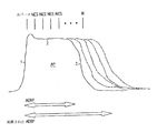
すべての興奮可能な組織と同様に、心筋細胞は、細胞の残存電位差が閾値電位差に脱分極されるとき、活動電位と呼ばれる膜内外電位差の迅速な変化を生成することが可能である。結果として生じる脱分極は、そのとき機械的収縮の原因となる細胞内反応を開始し、心筋全体を通じて広がる興奮波形として隣接する細胞へ伝播させる。図1は、隣接する組織からの興奮の伝導か、ペーシング・パルスの付加のいずれかによって細胞が興奮されたときに細胞内電極から記録されるような心房筋肉細胞の活動電位APを示している。活動電位は、細胞が迅速に脱分極される興奮フェイズ1と、脱分極された状態が維持される停滞フェイズ2と、細胞がその静止膜電位に戻る再分極フェイズ3とに分割されてもよい。心筋細胞は、さらなる活動電位が生成されることができない分極化された後の時間の間、興奮に対して無反応である。不応期は、その間に刺激が細胞を興奮させることや活動電位を生成することができない絶対不応期と、その間に通常よりも大きな刺激が活動電位を生成するために必要とされる相対不応期に再分割される。心房筋肉細胞内での絶対不応期と相対不応期の和は、心房有効不応期(AERP)と呼ばれる。図1に示すように、AERPの継続時間は、活動電位の継続時間にほぼ対応する。
As with all excitable tissues, cardiomyocytes can generate a rapid change in transmembrane potential called action potential when the residual potential difference of the cell is depolarized to a threshold potential difference. The resulting depolarization then initiates an intracellular reaction that causes mechanical contraction and propagates to adjacent cells as an excitatory waveform that spreads throughout the myocardium. FIG. 1 shows an atrial muscle cell action potential AP as recorded from an intracellular electrode when the cell is excited either by conduction of excitement from adjacent tissue or by application of a pacing pulse. . The action potential may be divided into an
心筋細胞の無反応性は、活動電位を開始させるための公称閾値電位以下又はそれを超える電位のいずれかである非興奮電気パルスによって不応期の間に細胞が刺激された場合、延長される。図1は、活動電位APを生じさせ、次に、心房細胞が絶対的に無反応である停滞フェイズ中に送られるn個の非励磁刺激パルスNESによって追従される心房ペーシング・パルス、Aペースを示している。細胞が絶対的に無反応であるため、非興奮刺激パルスは、閾値下又は閾値上のいずれかであってよい。図に示すように、非励磁刺激パルスの付加は、AERPを延ばし、心房基質を効果的に変更し、したがって細動に対する組織の感受性を減少させる。 Cardiomyocyte unresponsiveness is prolonged when cells are stimulated during the refractory period by a non-excited electrical pulse that is either below or above the nominal threshold potential for initiating the action potential. FIG. 1 shows the action of an atrial pacing pulse, A-pace, which is followed by n non-excited stimulation pulses NES that are generated during the stagnation phase in which the action potential AP is generated and the atrial cells are absolutely unresponsive. Show. Because the cells are absolutely unresponsive, the non-exciting stimulus pulse can be either sub-threshold or above threshold. As shown in the figure, the addition of a non-excited stimulation pulse prolongs the AERP and effectively alters the atrial matrix, thus reducing the tissue's sensitivity to fibrillation.
以下で説明するように、心臓リズム管理装置は、AERPを延ばすためにペーシング後の不応期中に非励磁刺激とともに心房ペーシングを送るように構成されている。このようなAERP延長ペーシングは、心房徐細動ショック又は心房ATP治療の付加の後など、治療条件が正当であるときはいつでも、心房細動が生じる可能性を低下させるために使用することができる。 As described below, the cardiac rhythm management device is configured to deliver atrial pacing with a non-excited stimulus during the refractory period after pacing to prolong the AERP. Such AERP extended pacing can be used to reduce the likelihood of atrial fibrillation whenever the treatment condition is justified, such as after the addition of atrial fibrillation shock or atrial ATP therapy. .
1.ハードウェア・プラットホーム
心臓リズム管理装置は、心臓リズムの不調を治療するために、選択された心臓の室に電気刺激を供給するペース・メーカ及び電気徐細動器/徐細動器を備える埋め込み可能な装置である。このような装置は、患者の胸の皮下に通常埋め込まれ、上部静脈系の血管を通って心臓内へ螺合された導線によってそれぞれの刺激される又は感知される心臓の室用の電極に接続されている。ペース・メーカは、タイミング化されたペーシング・パルスで心臓をペーシングする心臓リズム管理装置である。本明細書で使用されるような「ペース・メーカ」という用語は、その中に組み込まれたペース・メーカを備える電気徐細動器/徐細動器などの、ペーシング機能を備える装置を意味する。
1. Hardware platform Cardiac rhythm management device is implantable with pacemaker and electrical defibrillator / defibrillator supplying electrical stimulation to selected heart chambers to treat cardiac rhythm upset Device. Such devices are usually implanted subcutaneously in the patient's chest and connected to the respective stimulated or sensed heart chamber electrodes by leads threaded into the heart through blood vessels in the upper venous system. Has been. A pacemaker is a cardiac rhythm management device that paces the heart with timed pacing pulses. The term “pacemaker” as used herein means a device with a pacing function, such as an electrical defibrillator / defibrillator with a pacemaker incorporated therein. .
以下に続く説明では、マイクロ・プロセッサ・ベースの心臓リズム管理装置が、本発明のものであるシステムと方法に組み込まれるものとして参照される。説明される実施形態では、本発明は、メモリ内でプログラミングされた指令を実行するマイクロ・プロセッサから構成されるコントローラを実装している。しかし、心臓リズム管理装置のある機能は、カスタム論理回路(たとえば専用のハードウェア)かプロセッサ実行可能な指令のいずれかによって制御されることができることを理解されたい。本明細書で使用されるとき、「回路」又は「プログラミングされたコントローラ」という用語は、付随する回路要素に沿ったメモリ内に含まれるカスタム回路(すなわち専用ハードウェア)かプロセッサ実行可能な指令のいずれかを包含するものである。 In the description that follows, a microprocessor-based cardiac rhythm management device is referred to as being incorporated into the system and method of the present invention. In the described embodiment, the present invention implements a controller comprised of a microprocessor that executes instructions programmed in memory. However, it should be understood that certain functions of the cardiac rhythm management device can be controlled by either custom logic (eg, dedicated hardware) or processor-executable instructions. As used herein, the term “circuit” or “programmed controller” refers to a custom circuit (ie, dedicated hardware) or processor-executable instructions contained in memory along with associated circuit elements. Any one is included.
図2は、AFを治療するため、及び心房有効不応期を延ばすために値用を施すのに適したペーシング機能を備えるマイクロ・プロセッサ・ベースの心臓リズム管理装置のシステム図を示している。装置のコントローラ10は、双方向データ・バスを通してメモリ12と連絡しているマイクロ・プロセッサである。メモリ12は、たとえば、プログラム格納用のROM(リード・オンリー・メモリ)とデータ格納用のRAM(ランダム・アクセス・メモリ)を備えてもよい。装置は、電極34a〜b、導線33a〜b、感知増幅器31a〜b、パルス発生器32a〜b、さらにマイクロ・プロセッサ10と双方向に連絡している心房チャネル・インターフェイス30a〜bを備える心房感知及びペーシング・チャネルを有する。電極24、導線23、感知増幅器21、パルス発生器22、心室チャネル・インターフェイス20を備える心室感知/ペーシング・チャネルも設けられている。装置は、追加の心房部位又は心室を感知及び/又はペーシングするための追加のチャネルを有してもよい。図示した装置では、単一の電極が、各チャネル内で感知及びペーシングするために使用されており、単極導線として公知である。他の実施形態は、ペーシング・パルスを出力する及び/又は固有活性を感知する2つの電極を備える双極性導線を使用している。チャネル・インターフェイス30a〜bは、感知増幅器からの感知信号入力をデジタル化するためのアナログ・デジタル変換器と、ペーシング・パルスを出力し、ペーシング・パルス振幅を変更し、感知振幅のためのゲインや閾値を調節するためにマイクロ・プロセッサによって書き込まれるレジスタとを備える。ショック・パルス発生器50は、心房領域に近接して配置された1対のショック電極51a、51bを介して心房徐細動ショック・パルスを送るためのコントローラと接合されている。遠隔インターフェイス40は、外部プログラマと通信する。
FIG. 2 shows a system diagram of a microprocessor-based cardiac rhythm management device with a pacing function suitable for treating AF and applying values to prolong the effective atrial refractory period . The
コントローラ10は、メモリ内に格納されたプログラミングされた指令に従って装置の全体動作を制御する。それらにはペーシング・チャネルを介してのペースの伝送を制御すること、感知チャネルから受信された感知信号を解釈すること、補充収縮間隔と感覚不応期を決めるためのタイマを実装することを含む。ペース・メーカの感知回路は、特定のチャネルによって発生させられた電気記録信号(すなわち、心臓の電気的活動を表す電極によって感知された電圧)が特定の検知閾値を越えたとき、室感知を検知する。室感知は、心房又は心室感知チャネルのどちらで生じたかに応じて心房感知か心室感知のいずれであってもよい。特定のペーシング・モードで使用されるペーシング・アルゴリズムは、ペーシングを起動又は阻止するためにこのような感知を使用する。
The
コントローラは、連続する感知の間の間隔を測定することによって心房及び/又は心室の固有速度を決定してもよい。細動などの心房性不整脈を、速度ベースの基準を使用してこのようにして検知することができる。装置は、徐細動ショックや抗頻拍ペーシングなど、心房性頻脈性不整脈が検知されたときに心房に電気刺激治療を施すように構成されてもよい。心房細動のこのような検知の際、たとえばコントローラが、心房への徐細動ショックの伝送を生じさせるようにプログラミングされてもよい。次の感知が、心房細動が持続していると判定した場合、装置は、指定された回数のショックを繰り返し、細動の終了の成功が達成される。装置は、ショック・パルスを心房に送ることによって心房細動を終了させるが、結果としての脱分極も心室へ広がる。したがって、このような心房ショック・パルスが、心房細動よりも悪い状態である心室細動を実際に誘発する可能性があるというリスクがある。心室は、前の心室収縮の終わりに近すぎるときに(すなわち、EKG上のT波の近くで)送られる分極化ショックによって細動の誘発の影響を特に受けやすい。心室細動を誘発するリスクは、固有の心室リズムが指定の最大速度以下になるまで心房ショック・パルスの伝送を遅らせ、次に感知された心室脱分極、すなわちR波と同期するようにショックを送ることによって減少させることができる。装置は、心室に徐細動ショックを送るためのショック・パルス発生器やショック電極対を有してもよい。 The controller may determine the intrinsic velocity of the atrium and / or ventricle by measuring the interval between successive senses. Atrial arrhythmias such as fibrillation can be detected in this way using a speed-based criterion. The device may be configured to provide electrical stimulation therapy to the atrium when an atrial tachyarrhythmia is detected, such as bradyfibrillation shock or anti-tachycardia pacing. Upon such detection of atrial fibrillation, for example, a controller may be programmed to cause transmission of a slow fibrillation shock to the atrium. If the next sensing determines that atrial fibrillation is sustained, the device repeats the specified number of shocks and successful termination of fibrillation is achieved. The device terminates atrial fibrillation by sending a shock pulse to the atria, but the resulting depolarization also extends to the ventricles. Thus, there is a risk that such atrial shock pulses may actually induce ventricular fibrillation, a condition worse than atrial fibrillation. The ventricles are particularly susceptible to induction of fibrillation by polarized shocks that are sent when they are too close to the end of the previous ventricular contraction (ie, near the T wave on the EKG). The risk of inducing ventricular fibrillation is to delay the transmission of the atrial shock pulse until the intrinsic ventricular rhythm is below the specified maximum rate, and then the shock to synchronize with the sensed ventricular depolarization, ie, the R wave. Can be reduced by sending. The device may have a shock pulse generator or a shock electrode pair for delivering a fibrillation shock to the ventricle.
2.ペーシング・モード
徐脈ペーシング・モードは、ある最小心拍を強化するようにして心房及び/又は心室をペーシングするために使用されるペーシング・アルゴリズムである。このようなモードは、コード内のそれぞれの文字がペース・メーカの特定の機能を表す、3つの位置の文字コードによって一般に示されている。ペース・メーカは、非同期的か同期的のいずれかで最小心拍を強化することができる。非同期ペーシングでは、心臓が、固有の心臓活動に関係なく固定された速度でペーシングされる。非同期ペーシングとともに不整脈を誘発するリスクのため、徐脈を治療するための大部分のペース・メーカは、感知された心臓事象が、ペーシング・パルスを起動又は阻止する所定の間隔内で生じるいわゆるデマンド・モードと同時に動作するようにプログラミングされている。阻止デマンド・ペーシング・モードは、感知された固有活動に従ってペーシングを制御するために補充収縮間隔を使用する。阻止デマンド・モードでは、ペーシング・パルスは、その間に室による固有の心拍が検知されない所定の補充収縮間隔の終了後のみの心臓サイクル中に、心臓室に送られる。たとえば、心室補充収縮間隔は、それぞれの心室感知又はペーシングが再開されるように、心室事象の間で決められる。ペース・メーカは、固有のデマンドを基にして心房をペーシングするように構成されてもよい。心房補充収縮間隔が、心房感知が心房ペーシングが送られる前の心室感知又はペーシングの後で検知されなければならない最大時間間隔として定義される。
2. Pacing Mode Bradycardia pacing mode is a pacing algorithm that is used to pace the atrium and / or ventricle to enhance some minimum heart rate. Such a mode is generally indicated by a three-position character code where each character in the code represents a specific function of the pacemaker. The pacemaker can enhance the minimum heart rate either asynchronously or synchronously. In asynchronous pacing, the heart is paced at a fixed rate regardless of intrinsic cardiac activity. Due to the risk of triggering arrhythmias with asynchronous pacing, most pacemakers for treating bradycardia are so-called demand-demands where a sensed cardiac event occurs within a predetermined interval that triggers or blocks a pacing pulse. It is programmed to run simultaneously with the mode. The blocking demand pacing mode uses refill contraction intervals to control pacing according to the sensed intrinsic activity. In the blocking demand mode, pacing pulses are sent to the heart chamber during the cardiac cycle only after the end of a predetermined supplemental contraction interval during which no chamber-specific heartbeat is detected. For example, the ventricular replacement interval is determined between ventricular events such that each ventricular sensing or pacing is resumed. The pacemaker may be configured to pace the atria based on unique demands. An atrial replenishment contraction interval is defined as the maximum time interval that atrial sensing must be sensed after ventricular sensing or pacing before atrial pacing is sent.
ATP治療のためのペーシング・プロトコルは、検知された脱分極とタイミング化された関係で1つ又は複数のパルスを送るものと、検知された脱分極の後で開始する特定の時間の間連続的なパルス列を送るものの2つに一般に分けることができる。両方のタイプのATPプロトコルが、ペーシング・パルスによって作成される再入脱分極波面を遮断することを試みている。第1のグループのプロトコルは、送られるパルス数を決める変数や使用される特定のタイミングに応じて様々である。第2のグループのプロトコルは、短い列のパルスが指定の時間の間送られる、いわゆるバースト・ペーシングを含み、継続時間、周波数、パルスのタイミングを定義する変数に応じて様々である。 A pacing protocol for ATP therapy is one that sends one or more pulses in a timed relationship with the sensed depolarization and is continuous for a specific time starting after the sensed depolarization. In general, it can be divided into two types that send a simple pulse train. Both types of ATP protocols attempt to block the reentry depolarization wavefront created by the pacing pulse. The first group of protocols varies depending on the variables that determine the number of pulses sent and the specific timing used. The second group of protocols includes so-called burst pacing, in which short trains of pulses are sent for a specified time, and vary depending on variables that define duration, frequency, and pulse timing.
3.装置構成
図2に示すものなどの装置は、いくつかの方式での有効心房不応期延長を伴って心房ペーシングを送るように構成されている。例示的なデュアル・サイト構成では、第1のペーシング・チャネルの電極が、右心房をペーシングするために右心房に配置され、第2のペーシング・チャネルの電極が非興奮刺激の伝送のために冠状静脈洞を介して左心房の近くに配置される。他の構成は、ペーシング・チャネル及び1つ又は複数の非興奮刺激電極が複数の心房部位に配置される、心房ペーシング・チャネル及び1つ又は複数の専用の刺激チャネルを使用してもよい。他の装置は、単一の部位構成でペーシング及び非興奮パルスを送るために同じペーシング・チャネル及び電極を使用してもよい。単一部位又は複数部位の構成のいずれでも、装置のコントローラは、ペーシング・チャネルを介して心房をペーシングし、上記で説明したようにペーシング・パルスの後で1つ又は複数の非興奮刺激を送るAERP延長モードでプログラミングされる。図3は、ECGに関するペーシング・チャネル又はチャネルPCでの事象の例を示している。心房ペーシング・パルスAPが、非興奮刺激パルスNSPによって追従され、ここで、パルスNSPは、心房不応期の間伝送され、したがってそれらの振幅は、心房組織を興奮するために必要な閾値電圧を超えるかそれ以下のいずれかである。心房不応期は、心房ペーシングの後の指定された時間として装置のプログラミングで決められる。心房不応期は、特定の患者に対して個々に決めてもよい、又は典型的な心房繊維の不応期を表す公称値(たとえば150ms)として選択されてもよい。
3. Device Configuration Devices such as those shown in FIG. 2 are configured to deliver atrial pacing with an effective atrial refractory period extension in several ways. In an exemplary dual site configuration, a first pacing channel electrode is placed in the right atrium to pace the right atrium, and a second pacing channel electrode is coronary for the transmission of non-excitatory stimuli. Located near the left atrium via the sinus. Other configurations may use an atrial pacing channel and one or more dedicated stimulation channels in which a pacing channel and one or more non-excitable stimulation electrodes are placed at multiple atrial sites. Other devices may use the same pacing channel and electrode to deliver pacing and non-excitation pulses in a single site configuration. In either a single-site or multi-site configuration, the device controller paces the atrium via the pacing channel and delivers one or more non-excitable stimuli after the pacing pulse as described above. Programmed in AERP extended mode. FIG. 3 shows an example of an event on a pacing channel or channel PC for ECG. The atrial pacing pulse AP is followed by a non-excitatory stimulation pulse NSP, where the pulses NSP are transmitted during the atrial refractory period , and therefore their amplitude exceeds the threshold voltage required to excite the atrial tissue Or less. The atrial refractory period is determined by device programming as a specified time after atrial pacing. The atrial refractory period may be determined individually for a particular patient or may be selected as a nominal value (eg, 150 ms) that represents a typical atrial fiber refractory period .
4.オーバー・ドライブ・ペーシング
AERP延長モードで使用される徐脈ペーシング・モードは、好ましくは、心房感知が心房ペーシングを阻止する阻止デマンド・モードである。不応期を延ばす非興奮刺激が、ペーシングされた心拍中での出力に過ぎないため、ペーシング速度が固有の心拍よりも大きくなるように心房補充収縮間隔を減少させることによって、心房ペーシングの周波数を増加させることが望ましい。これをオーバー・ドライブ・ペーシングと呼ぶ。このようなオーバー・ドライブ・ペーシング・モードは、心房感知が検知されたときに間隔が減少し、各ペーシングされた心拍の後ゆっくりと増加するように、心房補充収縮間隔を動的に調節することによって実現される。
4). Overdrive pacing The bradycardia pacing mode used in the AERP prolongation mode is preferably a blocking demand mode where atrial sensing prevents atrial pacing. Increased atrial pacing frequency by reducing the interval between atrial replenishment contractions so that the pacing rate is greater than the intrinsic heart rate, as non-excitatory stimuli that extend the refractory period are only output during the paced heartbeat It is desirable to make it. This is called overdrive pacing. Such an overdrive pacing mode dynamically adjusts the atrial replenishment contraction interval so that the interval decreases when an atrial sense is detected and slowly increases after each paced heartbeat. It is realized by.
心房オーバー・ドライブ・ペーシングの一実施形態では、心房補充収縮間隔が、心房感知が行われたときのA−A間隔(心房検知と前の心臓感知又はペーシングの間の時間間隔として定義される)を測定し、次に測定されたA−A間隔を基にして更新された心房補充収縮間隔を計算することによってプログラミングされた最小値に向かって減少するように調節される。心房ペーシングが送られるとき、他方では、心房補充収縮間隔が、心房ペーシング速度がそのプログラミングされた底値へ減衰するようにゆっくりと増加するようにされる。図4A、4Bは、コントローラ10(a.k.a.ファームウェア)によって及び/又は離散型構成要素として実行されるソフトウェアとして実装される1つのフィルタ515、516で構成されるオーバー・ドライブ・ペーシング・システムの例示的な実施形態を示している。フィルタ515は、心房感知が行われたとき、更新された心房補充収縮間隔を計算するために使用され、フィルタ516は、心房ペーシングが送られるとき使用される。心房感知が行われるとき、計測されたA−A間隔は、その出力が更新された心房反復補充収縮間隔であるデジタル・フィルタ515への入力である。フィルタ515は、測定されたA−A間隔にフィルタ係数Aを乗じ、次に前の出力の値(すなわち現在の心房補充収縮間隔)にフィルタ係数Bを乗じた結果を加える。したがって、フィルタの動作は、AEIn=X(AAn)+Y(AEIn−1)によって表される。ここでX、Yは選択された係数、AAnは、最も最近のA−A間隔持続時間、AEIn−1は、心房補充収縮間隔の前の値である。このようにして、フィルタは、心房補充収縮間隔の値をフィルタ係数によって決定される速度のスケール・ファクタを乗じた現在のA−A間隔に向かって移動させる。心房ペーシングが、心房感知なしでの心房補充収縮間隔の終了によって送られるとき、フィルタ516は、AEIn=Z(AEIn−1)となるように現在の心房補充収縮間隔にフィルタ係数Zを乗じる。安定した動作を提供するために、係数Zは、1よりも大きい値に設定されなければならない。そのときフィルタ516は、補充収縮間隔の連続的な値が心房補充収縮間隔の底値までフィルタに入力されるため、各ペーシングとともに心房補充収縮間隔を指数的に増加させる。心房をオーバー・ドライブさせるために、心房補充収縮間隔が、心房感知が行われたとき現在のA−A間隔よりも小さい値に向かって迅速に減少し、ペーシングが伝送されたときプログラミングされた底値に向かってゆっくりと増加するように、フィルタ515、516の係数が選択される。
In one embodiment of atrial overdrive pacing, the atrial refill contract interval is the AA interval when atrial sensing is performed (defined as the time interval between atrial sensing and previous cardiac sensing or pacing). , And then adjusted to decrease towards the programmed minimum by calculating an updated atrial replacement contraction interval based on the measured AA interval. When an atrial pacing is delivered, on the other hand, the atrial replacement contraction interval is allowed to increase slowly so that the atrial pacing rate decays to its programmed floor. 4A and 4B illustrate an overdrive pacing configuration comprising a
5.AERP延長ペーシングの開始
コントローラは、外部プログラマからの指令の際、指定の時間の間、周期的に、又は通常動作中の他の指定の時間に、又は感知された事象に応答して、AERP延長モードに入るようにプログラミングされる。AERP延長ペーシングが特に有益である、ある特定の状況は、心房徐細動ショックの後の時間である。心房徐細動ショックのすぐ後に続く約1分間、心房が、極めて影響を受けやすい時間にあることが見出された。この時間の間、心房有効不応期は、心房徐細動の間のその値から短縮される。この状態は、患者に心房細動又はERAFと一般に呼ばれる、心房細動のショック後再開始に陥りやすくさせる。この状況に対処するために、装置は、心房細動の検知の際、AERP延長ペーシングによって追従される細動を終了させるために、特定の時間の間心房徐細動ショックが送られるようにプログラミングされることができる。装置はまた、心房抗頻拍ペーシングの伝送の後の特定の時間の間AERP延長ペーシングを送るようにプログラミングされてもよい。
5). Initiation of AERP Extended Pacing The controller, when commanded by an external programmer, may extend the AERP extension for a specified time, periodically, or at another specified time during normal operation, or in response to a sensed event. Programmed to enter mode. One particular situation where AERP prolonged pacing is particularly beneficial is the time after an atrial fibrillation shock. It was found that the atrium is at a very sensitive time for about 1 minute immediately following the atrial fibrillation shock. During this time, the atrial effective refractory period is reduced from that value during atrial fibrillation. This condition makes the patient more prone to restart after a shock of atrial fibrillation, commonly referred to as atrial fibrillation or ERAF. To address this situation, the device is programmed to deliver an atrial fibrillation shock for a specific time to terminate fibrillation followed by AERP extended pacing upon detection of atrial fibrillation. Can be done. The device may also be programmed to send AERP extended pacing for a specific time after transmission of the atrial anti-tachycardia pacing.
本発明を前述の特定の実施形態とともに説明してきたが、多くの代替形態、変形形態及び修正形態が、当業者に理解されるであろう。このような代替形態、変形形態及び修正形態は、頭記に添付された特許請求の範囲の範囲内にあることを意図されている。 While the invention has been described in conjunction with the specific embodiments described above, many alternatives, variations and modifications will be apparent to those skilled in the art. Such alternatives, variations and modifications are intended to be within the scope of the claims appended hereto.
Claims (26)
心房ペーシング・パルスを送るための心房ペーシング・チャネルと、
心房徐細動ショックを送るためのショック・パルス発生器と、
コントローラと備え、そのコントローラが
心房細動を検知すること、
心房細動が検知された後、心房徐細動ショックを送ること、
心房徐細動ショックの後の特定の時間の間ペーシング・モードに従って心房ペーシング・パルスを送ること、
心房ペーシング・パルスの後の心房不応期の間、1つ又は複数の非興奮刺激パルスを心房に送ることを含む機能を行うために実行可能な指令でプログラミングされている、心臓リズム管理装置。An atrial sensing channel for sensing electrical activity of the atrium;
An atrial pacing channel for delivering atrial pacing pulses;
A shock pulse generator for delivering an atrial fibrillation shock;
With a controller, that controller detects atrial fibrillation,
Sending atrial fibrillation shock after atrial fibrillation is detected,
Sending an atrial pacing pulse according to a pacing mode for a specific time after an atrial fibrillation shock;
A cardiac rhythm management device programmed with instructions executable to perform functions including delivering one or more non-excitatory stimulation pulses to the atrium during an atrial refractory period following an atrial pacing pulse.
ペーシング・パルスを心房に送るための第1の心房ペーシング・チャネルと、
コントローラとを備え、前記コントローラが、
心房細動を検知すること、
心房細動の検知後、心房抗頻拍ペーシングを送ること、
心房抗頻拍ペーシングの後の特定の時間の間、徐脈ペーシング・モードに従って心房ペーシング・パルスを送ること、
徐脈ペーシング・モードでのペーシングをしながら、心房ペーシング・パルスの後の心房不応期の間、1つ又は複数の非興奮心房刺激パルスを心房に送ること
を含む機能を行うための実行可能な指令でプログラミングされた心臓リズム管理装置。An atrial sensing channel for sensing electrical activity of the atrium;
A first atrial pacing channel for sending pacing pulses to the atrium;
A controller, the controller comprising:
Detecting atrial fibrillation,
Sending atrial anti-tachycardia pacing after detection of atrial fibrillation,
Sending an atrial pacing pulse according to the bradycardia pacing mode for a specific time after an atrial anti-tachycardia pacing;
Feasible to perform functions including sending one or more non-excited atrial stimulation pulses to the atrium during the atrial refractory period after the atrial pacing pulse while pacing in bradycardia pacing mode Cardiac rhythm management device programmed with commands.
心房細動の検知の際、心房徐細動ショックを送るための手段と、
心房徐細動ショックの後の特定の時間の間ペーシング・モードに従って心房ペーシング部位へ心房ペーシング・パルスを送るための手段と、
特定の時間の間の各心房ペーシング・パルスの後の心房不応期の間、1つ又は複数の非興奮刺激パルスを心房刺激部位に送るための手段と、を備える心臓リズム管理装置。Means for sensing atrial electrical activity to detect atrial fibrillation;
Means for delivering an atrial fibrillation shock upon detection of atrial fibrillation;
Means for delivering an atrial pacing pulse to an atrial pacing site according to a pacing mode for a specific time after an atrial fibrillation shock;
Means for delivering one or more non-excitatory stimulation pulses to the atrial stimulation site during an atrial refractory period after each atrial pacing pulse for a specified time.
心房細動の検知の際、抗頻拍ペーシングを送る手段、
前記抗頻拍ペーシングの後の特定の時間の間徐脈ペーシング・モードに従って心房ペーシング部位へ心房ペーシング・パルスを送る手段、
特定の時間の間の各心房ペーシング・パルスの後の心房不応期の間、1つ又は複数の非興奮刺激パルスを心房に送る手段を備える心臓リズム管理装置。Means for sensing atrial electrical activity to detect atrial fibrillation;
Means for sending anti-tachycardia pacing upon detection of atrial fibrillation,
Means for sending an atrial pacing pulse to an atrial pacing site according to a bradycardia pacing mode for a specific time after said anti-tachycardia pacing;
A cardiac rhythm management device comprising means for delivering one or more non-excitatory stimulation pulses to the atrium during the atrial refractory period after each atrial pacing pulse for a specified time.
Applications Claiming Priority (2)
| Application Number | Priority Date | Filing Date | Title |
|---|---|---|---|
| US10/302,747 US7203538B2 (en) | 2002-11-22 | 2002-11-22 | Pacing therapy for extending atrial refractory period |
| PCT/US2003/037155 WO2004047918A1 (en) | 2002-11-22 | 2003-11-20 | Pacing therapy for extending atrial refractory period |
Publications (3)
| Publication Number | Publication Date |
|---|---|
| JP2006507093A JP2006507093A (en) | 2006-03-02 |
| JP2006507093A5 JP2006507093A5 (en) | 2010-01-28 |
| JP4594735B2 true JP4594735B2 (en) | 2010-12-08 |
Family
ID=32324865
Family Applications (1)
| Application Number | Title | Priority Date | Filing Date |
|---|---|---|---|
| JP2004555514A Expired - Fee Related JP4594735B2 (en) | 2002-11-22 | 2003-11-20 | Pacing treatment to prolong the atrial refractory period |
Country Status (7)
| Country | Link |
|---|---|
| US (2) | US7203538B2 (en) |
| EP (1) | EP1562676B1 (en) |
| JP (1) | JP4594735B2 (en) |
| AT (1) | ATE357271T1 (en) |
| AU (1) | AU2003291815A1 (en) |
| DE (1) | DE60312723T2 (en) |
| WO (1) | WO2004047918A1 (en) |
Cited By (1)
| Publication number | Priority date | Publication date | Assignee | Title |
|---|---|---|---|---|
| US9814895B2 (en) | 2007-12-11 | 2017-11-14 | The Washington University | Method and device for three-stage atrial cardioversion therapy |
Families Citing this family (11)
| Publication number | Priority date | Publication date | Assignee | Title |
|---|---|---|---|---|
| US7203538B2 (en) * | 2002-11-22 | 2007-04-10 | Cardiac Pacemakers, Inc. | Pacing therapy for extending atrial refractory period |
| US8175702B2 (en) | 2004-11-04 | 2012-05-08 | The Washington University | Method for low-voltage termination of cardiac arrhythmias by effectively unpinning anatomical reentries |
| US8046064B2 (en) * | 2006-04-24 | 2011-10-25 | Medtronic, Inc. | Method of delivering PESP/ICC as well as adjusting the refractory period of the heart |
| US8478406B2 (en) * | 2006-04-24 | 2013-07-02 | Medtronic, Inc. | Apparatus and methods of delivering an enhanced refractory period stimulation therapy |
| US7729763B2 (en) * | 2006-05-18 | 2010-06-01 | Medtronic, Inc. | Post long pause overdrive pacing in response to atrial tachyarrythmia episode |
| US7869867B2 (en) * | 2006-10-27 | 2011-01-11 | Cyberonics, Inc. | Implantable neurostimulator with refractory stimulation |
| US8874208B2 (en) | 2007-12-11 | 2014-10-28 | The Washington University | Methods and devices for three-stage ventricular therapy |
| US8369938B2 (en) | 2010-08-06 | 2013-02-05 | Cardiac Pacemakers, Inc. | Rhythm discrimination enhancement—chamber of tachy origination |
| US8403830B2 (en) | 2010-08-06 | 2013-03-26 | Cardiac Pacemakers, Inc. | Rhythm discrimination enhancement—AV drive |
| US9675806B2 (en) | 2012-10-09 | 2017-06-13 | Medtronic, Inc. | Cardiac pacing during medical procedures |
| EP4048382A2 (en) | 2019-10-23 | 2022-08-31 | Impulse Dynamics NV | Methods for planning and delivering cardiac electrical stimulation |
Family Cites Families (12)
| Publication number | Priority date | Publication date | Assignee | Title |
|---|---|---|---|---|
| US4554922A (en) | 1982-09-30 | 1985-11-26 | Prystowsky Eric N | Method of inhibiting cardiac arrhythmias |
| EP0647151B1 (en) | 1992-06-30 | 1997-01-15 | Medtronic, Inc. | Apparatus for treatment of angina |
| US5344221A (en) * | 1993-01-27 | 1994-09-06 | Macwilliam Mark W | Anti-theft method and apparatus for locking the brakes of a vehicle |
| JP4175662B2 (en) * | 1996-01-08 | 2008-11-05 | インパルス ダイナミクス エヌ.ヴイ. | Electric muscle control device |
| DE69732774T2 (en) | 1996-01-08 | 2006-02-02 | Impulse Dynamics N.V. | Device for controlling cardiac activity using non-excitatory pre-stimulation |
| WO1997027797A2 (en) | 1996-02-05 | 1997-08-07 | Shlomo Ben-Haim | Electrical muscle controller |
| EP0811399A3 (en) | 1996-06-04 | 1999-05-12 | INCONTROL, Inc. | Post atrial cardioversion high rate atrial pacing with gradual rate return |
| US5645569A (en) * | 1996-06-04 | 1997-07-08 | Incontrol, Inc. | Post atrial cardioversion atrial pacing and method |
| US5741311A (en) | 1996-06-27 | 1998-04-21 | Medtronic, Inc. | Implantable medical device system with method for determining lead condition |
| EP1023917B1 (en) | 1999-01-28 | 2004-07-14 | SORIN BIOMEDICA CRM S.r.l. | A device for cardiac stimulation with electrotonic inhibition |
| US6377852B1 (en) | 2000-01-20 | 2002-04-23 | Pacesetter, Inc. | Implanatable cardiac stimulation device and method for prolonging atrial refractoriness |
| US7203538B2 (en) * | 2002-11-22 | 2007-04-10 | Cardiac Pacemakers, Inc. | Pacing therapy for extending atrial refractory period |
-
2002
- 2002-11-22 US US10/302,747 patent/US7203538B2/en not_active Expired - Fee Related
-
2003
- 2003-11-20 AT AT03769000T patent/ATE357271T1/en not_active IP Right Cessation
- 2003-11-20 AU AU2003291815A patent/AU2003291815A1/en not_active Abandoned
- 2003-11-20 DE DE60312723T patent/DE60312723T2/en not_active Expired - Lifetime
- 2003-11-20 EP EP03769000A patent/EP1562676B1/en not_active Expired - Lifetime
- 2003-11-20 JP JP2004555514A patent/JP4594735B2/en not_active Expired - Fee Related
- 2003-11-20 WO PCT/US2003/037155 patent/WO2004047918A1/en active IP Right Grant
-
2007
- 2007-03-19 US US11/687,776 patent/US7991469B2/en not_active Expired - Fee Related
Cited By (1)
| Publication number | Priority date | Publication date | Assignee | Title |
|---|---|---|---|---|
| US9814895B2 (en) | 2007-12-11 | 2017-11-14 | The Washington University | Method and device for three-stage atrial cardioversion therapy |
Also Published As
| Publication number | Publication date |
|---|---|
| US20040102811A1 (en) | 2004-05-27 |
| DE60312723T2 (en) | 2007-12-06 |
| US7203538B2 (en) | 2007-04-10 |
| AU2003291815A1 (en) | 2004-06-18 |
| US7991469B2 (en) | 2011-08-02 |
| ATE357271T1 (en) | 2007-04-15 |
| EP1562676A1 (en) | 2005-08-17 |
| EP1562676B1 (en) | 2007-03-21 |
| JP2006507093A (en) | 2006-03-02 |
| DE60312723D1 (en) | 2007-05-03 |
| WO2004047918A1 (en) | 2004-06-10 |
| US20070167987A1 (en) | 2007-07-19 |
Similar Documents
| Publication | Publication Date | Title |
|---|---|---|
| JP4395075B2 (en) | Stress-reducing pacing mode to prevent arrhythmia | |
| US7991469B2 (en) | Pacing therapy for extending atrial refractory period | |
| US7376464B2 (en) | Method and system for automatic anti-tachycardia pacing | |
| JP3212611B2 (en) | Implantable medical device for eliminating atrial fibrillation | |
| US8027719B2 (en) | Method and apparatus for delivering defibrillation shock therapy while reducing electrical dispersion due to ventricular conduction disorder | |
| US6889077B2 (en) | Implantable cardiac stimulation device that defibrillates the atria while avoiding the ventricular vulnerable period and method | |
| US6847842B1 (en) | Method and apparatus for reducing early recurrence of atrial fibrillation with defibrillation shock therapy | |
| JP4865713B2 (en) | ATP treatment for tachyarrhythmia | |
| EP2355894B1 (en) | Overlapping pacing and tachyarrhythmia detection zones | |
| US7110811B2 (en) | Method and apparatus for atrial tachyarrhythmia cardioversion | |
| US6721596B1 (en) | Atrial shock therapy with ventricular pacing | |
| JP4863991B2 (en) | ATP pacing with synchronized monitoring | |
| US8644924B2 (en) | Preferential mechanical unloading during anti-tachycardia pacing | |
| US7313438B2 (en) | Selective chamber ATP pacing | |
| EP1654034A2 (en) | Ventricular rate stabilization with cardiac resynchronization | |
| WO2004093991A1 (en) | Tachycardia synchronization delays |
Legal Events
| Date | Code | Title | Description |
|---|---|---|---|
| A621 | Written request for application examination |
Free format text: JAPANESE INTERMEDIATE CODE: A621 Effective date: 20061106 |
|
| RD02 | Notification of acceptance of power of attorney |
Free format text: JAPANESE INTERMEDIATE CODE: A7422 Effective date: 20090313 |
|
| RD03 | Notification of appointment of power of attorney |
Free format text: JAPANESE INTERMEDIATE CODE: A7423 Effective date: 20090313 |
|
| A131 | Notification of reasons for refusal |
Free format text: JAPANESE INTERMEDIATE CODE: A131 Effective date: 20090721 |
|
| A521 | Request for written amendment filed |
Free format text: JAPANESE INTERMEDIATE CODE: A821 Effective date: 20090723 |
|
| RD04 | Notification of resignation of power of attorney |
Free format text: JAPANESE INTERMEDIATE CODE: A7424 Effective date: 20090723 |
|
| A601 | Written request for extension of time |
Free format text: JAPANESE INTERMEDIATE CODE: A601 Effective date: 20091021 |
|
| A602 | Written permission of extension of time |
Free format text: JAPANESE INTERMEDIATE CODE: A602 Effective date: 20091028 |
|
| A524 | Written submission of copy of amendment under article 19 pct |
Free format text: JAPANESE INTERMEDIATE CODE: A524 Effective date: 20091124 |
|
| A131 | Notification of reasons for refusal |
Free format text: JAPANESE INTERMEDIATE CODE: A131 Effective date: 20100208 |
|
| A601 | Written request for extension of time |
Free format text: JAPANESE INTERMEDIATE CODE: A601 Effective date: 20100430 |
|
| A602 | Written permission of extension of time |
Free format text: JAPANESE INTERMEDIATE CODE: A602 Effective date: 20100512 |
|
| A521 | Request for written amendment filed |
Free format text: JAPANESE INTERMEDIATE CODE: A523 Effective date: 20100806 |
|
| TRDD | Decision of grant or rejection written | ||
| A01 | Written decision to grant a patent or to grant a registration (utility model) |
Free format text: JAPANESE INTERMEDIATE CODE: A01 Effective date: 20100906 |
|
| A01 | Written decision to grant a patent or to grant a registration (utility model) |
Free format text: JAPANESE INTERMEDIATE CODE: A01 |
|
| A61 | First payment of annual fees (during grant procedure) |
Free format text: JAPANESE INTERMEDIATE CODE: A61 Effective date: 20100917 |
|
| FPAY | Renewal fee payment (event date is renewal date of database) |
Free format text: PAYMENT UNTIL: 20130924 Year of fee payment: 3 |
|
| R150 | Certificate of patent or registration of utility model |
Free format text: JAPANESE INTERMEDIATE CODE: R150 |
|
| LAPS | Cancellation because of no payment of annual fees |