JP4594523B2 - Fuel cell device and method of generating electrical energy by fuel cell device - Google Patents
Fuel cell device and method of generating electrical energy by fuel cell device Download PDFInfo
- Publication number
- JP4594523B2 JP4594523B2 JP2000550166A JP2000550166A JP4594523B2 JP 4594523 B2 JP4594523 B2 JP 4594523B2 JP 2000550166 A JP2000550166 A JP 2000550166A JP 2000550166 A JP2000550166 A JP 2000550166A JP 4594523 B2 JP4594523 B2 JP 4594523B2
- Authority
- JP
- Japan
- Prior art keywords
- fuel cell
- unit
- stage
- cell unit
- compressor
- Prior art date
- Legal status (The legal status is an assumption and is not a legal conclusion. Google has not performed a legal analysis and makes no representation as to the accuracy of the status listed.)
- Expired - Fee Related
Links
Images
Classifications
-
- H—ELECTRICITY
- H01—ELECTRIC ELEMENTS
- H01M—PROCESSES OR MEANS, e.g. BATTERIES, FOR THE DIRECT CONVERSION OF CHEMICAL ENERGY INTO ELECTRICAL ENERGY
- H01M8/00—Fuel cells; Manufacture thereof
- H01M8/06—Combination of fuel cells with means for production of reactants or for treatment of residues
- H01M8/0606—Combination of fuel cells with means for production of reactants or for treatment of residues with means for production of gaseous reactants
- H01M8/0612—Combination of fuel cells with means for production of reactants or for treatment of residues with means for production of gaseous reactants from carbon-containing material
-
- H—ELECTRICITY
- H01—ELECTRIC ELEMENTS
- H01M—PROCESSES OR MEANS, e.g. BATTERIES, FOR THE DIRECT CONVERSION OF CHEMICAL ENERGY INTO ELECTRICAL ENERGY
- H01M2250/00—Fuel cells for particular applications; Specific features of fuel cell system
- H01M2250/20—Fuel cells in motive systems, e.g. vehicle, ship, plane
-
- H—ELECTRICITY
- H01—ELECTRIC ELEMENTS
- H01M—PROCESSES OR MEANS, e.g. BATTERIES, FOR THE DIRECT CONVERSION OF CHEMICAL ENERGY INTO ELECTRICAL ENERGY
- H01M8/00—Fuel cells; Manufacture thereof
- H01M8/04—Auxiliary arrangements, e.g. for control of pressure or for circulation of fluids
- H01M8/04007—Auxiliary arrangements, e.g. for control of pressure or for circulation of fluids related to heat exchange
- H01M8/04029—Heat exchange using liquids
-
- H—ELECTRICITY
- H01—ELECTRIC ELEMENTS
- H01M—PROCESSES OR MEANS, e.g. BATTERIES, FOR THE DIRECT CONVERSION OF CHEMICAL ENERGY INTO ELECTRICAL ENERGY
- H01M8/00—Fuel cells; Manufacture thereof
- H01M8/04—Auxiliary arrangements, e.g. for control of pressure or for circulation of fluids
- H01M8/04082—Arrangements for control of reactant parameters, e.g. pressure or concentration
- H01M8/04089—Arrangements for control of reactant parameters, e.g. pressure or concentration of gaseous reactants
- H01M8/04119—Arrangements for control of reactant parameters, e.g. pressure or concentration of gaseous reactants with simultaneous supply or evacuation of electrolyte; Humidifying or dehumidifying
- H01M8/04156—Arrangements for control of reactant parameters, e.g. pressure or concentration of gaseous reactants with simultaneous supply or evacuation of electrolyte; Humidifying or dehumidifying with product water removal
-
- Y—GENERAL TAGGING OF NEW TECHNOLOGICAL DEVELOPMENTS; GENERAL TAGGING OF CROSS-SECTIONAL TECHNOLOGIES SPANNING OVER SEVERAL SECTIONS OF THE IPC; TECHNICAL SUBJECTS COVERED BY FORMER USPC CROSS-REFERENCE ART COLLECTIONS [XRACs] AND DIGESTS
- Y02—TECHNOLOGIES OR APPLICATIONS FOR MITIGATION OR ADAPTATION AGAINST CLIMATE CHANGE
- Y02E—REDUCTION OF GREENHOUSE GAS [GHG] EMISSIONS, RELATED TO ENERGY GENERATION, TRANSMISSION OR DISTRIBUTION
- Y02E60/00—Enabling technologies; Technologies with a potential or indirect contribution to GHG emissions mitigation
- Y02E60/30—Hydrogen technology
- Y02E60/50—Fuel cells
-
- Y—GENERAL TAGGING OF NEW TECHNOLOGICAL DEVELOPMENTS; GENERAL TAGGING OF CROSS-SECTIONAL TECHNOLOGIES SPANNING OVER SEVERAL SECTIONS OF THE IPC; TECHNICAL SUBJECTS COVERED BY FORMER USPC CROSS-REFERENCE ART COLLECTIONS [XRACs] AND DIGESTS
- Y02—TECHNOLOGIES OR APPLICATIONS FOR MITIGATION OR ADAPTATION AGAINST CLIMATE CHANGE
- Y02T—CLIMATE CHANGE MITIGATION TECHNOLOGIES RELATED TO TRANSPORTATION
- Y02T90/00—Enabling technologies or technologies with a potential or indirect contribution to GHG emissions mitigation
- Y02T90/40—Application of hydrogen technology to transportation, e.g. using fuel cells
Landscapes
- Life Sciences & Earth Sciences (AREA)
- Engineering & Computer Science (AREA)
- Manufacturing & Machinery (AREA)
- Sustainable Development (AREA)
- Sustainable Energy (AREA)
- Chemical & Material Sciences (AREA)
- Chemical Kinetics & Catalysis (AREA)
- Electrochemistry (AREA)
- General Chemical & Material Sciences (AREA)
- Fuel Cell (AREA)
Description
【0001】
本発明は、後続配置の燃料電池ユニットを運転するために空気を供給しながら、エネルギー担体、特に液状原料から水素を発生するための改質ユニットを備え、この改質ユニットと燃料電池ユニットの間に、一酸化炭素を二酸化炭素に変換するための酸化装置が配置されている、請求項1の上位概念に記載した、特に自動車の駆動装置としての燃料電池装置に関する。本発明は更に、燃料電池ユニットを運転するために、水素が改質プロセスで空気を供給しながら原料から発生させられ、改質プロセスの後でかつ燃料電池ユニットの前に一酸化炭素が二酸化炭素に酸化される、請求項14の上位概念に記載した、特に自動車の駆動装置のための、燃料電池装置によって電気エネルギーを発生するための方法に関する。
【0002】
欧州特許第0217532号公報により、触媒水素発生器が知られている。この水素発生器はオートサーミック改質ユニット内でメタノールと空気の混合気から水素を発生する。この場合、改質ユニット内に熱電対が配置され、改質ユニット内の熱電対の場所の温度が上昇するにつれて空気供給が減らされるように、この熱電対がメタノールと空気の混合気への空気供給に影響を与える。
【0003】
この装置の発展形態の水素発生器がWO96/00186に記載されている。この場合、メタノールと空気の混合気が触媒を通って半径方向に流れるように、触媒はメタノールと空気の混合気のための入口管の周りに配置されている。
【0004】
ドイツ連邦共和国特許第4345319号公報とドイツ連邦共和国特許第4329323号公報には燃料電池電流発生装置が開示されている。この場合、改質ユニット内でメタノールと水素の混合気から水素が発生させられる。この水素は電気的なエネルギーを発生するための後続配置の燃料電池に供給される。改質器内で充分な反応熱を発生するために、メタノールの一部がメタノールと水の混合気に添加されないで、付加的なバーナー内で燃焼される。
【0005】
ドイツ連邦共和国特許出願公開第19629084号公報により、燃料電池からなる駆動バッテリを備えた電気自動車が知られている。この場合、燃料電池は走行風によって冷却されるように配置されている。
【0006】
ドイツ連邦共和国の定期刊行物である自動車技術(Autotechnik) 、第5/1997号、第20/21頁の記事“分かったぞ?(Heureka?)”には、燃料電池駆動装置を備えた自動車が記載されている。この場合、燃料電池を運転するために必要な水素は自動車自体でベンジンから作られる。その際、多段プロセスでベンジンが水素に変換される。変換の前に、ベンジンは蒸発器内で加熱によってガス状の状態になる。部分燃焼反応器内で酸素不足状態で水素と一酸化炭素が発生する。一酸化炭素を酸化するために、酸化銅触媒と酸化亜鉛触媒が設けられている。この場合、水蒸気は反応のための酸素供与体として供給される。他のステップでは、最後の約1%の一酸化炭素が慣用のプラチナ酸化触媒内で空気を供給しながら後燃焼させられる。このようにして得られた、水素、一酸化炭素および二酸化炭素の混合物はまだ10ppmの一酸化炭素を含んでいる。これは後続配置の燃料電池にとって問題がない。従って、熱交換器で約80°Cに冷却した後で、ガスは燃料電池に案内される。
【0007】
日本の定期刊行物であるアジア自動車レポート、1998年1月20日の第272巻、第34〜39頁の記事“代替燃料”により、自動車用の類似の燃料電池装置が知られている。この場合、メタノール改質ユニットが燃料電池用水素を発生するために設けられている。この場合、水素と酸素の電気化学的な反応時に発生する水は改質プロセスのために再び使用される。改質プロセスのために脱イオン化された水とメタノールが混合され、蒸発され、250°Cの温度で水素と二酸化炭素に変換される。この水素は燃料電池に供給され、この燃料電池はこの水素を空気中酸素と共に触媒プロセスで電気的なエネルギーと水に変換する。蒸発と改質プロセスのために必要な熱エネルギーは燃料電池の後に接続配置された触媒バーナーで発生させられる。このバーナーは燃料電池からの残留ガスで運転される。このガスは水素を含んでいる。なぜなら、燃料電池装置が供給される水素の約75%だけを利用するからである。充分な残留水素が触媒バーナーに供されない場合には、燃料タンクからのメタノールが改質器の熱を回収するために使用される。改質器で発生したガスを水素成分と共に導入開始する前に、このガスは触媒反応によって浄化される。この場合、一酸化炭素が二酸化炭素に変換される。自動車用の燃料電池装置の図示実施の形態では、メタノール改質器は蒸発器、改質器および一酸化炭素用酸化ユニットを備えている。
【0008】
ドイツ連邦共和国特許第4322765号公報には、燃料電池を備えた車両用のダイナミック出力制御のための方法と装置が開示されている。この燃料電池は電気式駆動ユニットに電気エネルギーを供給する。アクセルペダル位置に対応する要求出力から出発して、空気流量が計算される。この空気流量は燃料電池によって目標出力を準備するために必要である。燃料電池の吸込み管路内に配置したコンプレッサは必要な空気流に対応してその回転数が調節される。
【0009】
欧州特許第0629013号公報により、燃料電池装置の空気供給方法と装置が知られている。この場合、プロセス空気が燃料電池に入る前に圧縮機によって圧縮される。燃料電池を通過した後で、排出される排気はエネルギーを回収するためにタービンを経て減張される。この場合、タービン、圧縮機および付加的な駆動モータは共通の軸に配置されている。圧縮機は回転数を変更可能に形成され、排気を減張するためのタービンとしての膨張器と共に共通の軸に配置されている。吸収力を変更する膨張器の使用によって、燃料電池のための空気流調節が行われる。
【0010】
WO97/16648号公報により、冷蔵庫用ねじコンプレッサが知られている。このねじコンプレッサは2つのポンプ室を備えている。第1のポンプ室の出口は第2のポンプ室の二次入口に接続されている。
【0011】
本発明の根底をなす課題は、高効率で小型であると共に、特に自動車の駆動装置用の電気エネルギーを発生するための経済的で環境に優しい使用が可能となるように、冒頭に述べた種類の燃料電池装置を改良することである。
【0012】
この課題は本発明に従い、請求項1に記載した特徴を有する上記種類の燃料電池装置によって、および請求項14に記載した特徴を有する上記種類の方法によって解決される。本発明の有利な実施形は従属請求項に記載されている。
【0013】
そのために、燃料電池装置の場合、本発明に従い、空気用の二段型圧縮機が改質ユニットと燃料電池ユニットに付設されている。
【0014】
これは、管路長さが異なり、通過すべき段が互いに異なっているにもかかわらず、燃料電池ユニットのアノードとカソードのために同じ圧力が提供されるという利点がある。これはアノードとカソードの作用のためにきわめて重要である。燃料電池ユニットのカソードに空気を供給するために、比較的に低い圧力、例えば約2.5〜3.5バール、特に約3バールの圧力の空気流が圧縮機の第1段から取り出され、主として改質ユニット18の空気供給に役立つ圧縮機の第2段から、比較的に高い圧力、例えば約3.2〜4.2バール、特に約3.7バールの圧力の空気流が取り出される。第2段のこの高い圧力は、改質ユニットから酸化ユニットを経て燃料電池ユニットへの他の経路で発生する圧力損失を最初から考慮する。
【0015】
選定された圧力の絶対高さに依存しないで、第1段と第2段の間の圧力差は約0.5〜0.9バール、特に0.7バールである。
【0016】
二段型圧縮機またはコンプレッサは、ピストン式圧縮機、ねじ圧縮機またはねじコンプレッサまたは遠心圧縮機として形成可能である。
【0017】
経済性、特に必要スペースを更に改善するために、水噴射装置を酸化装置に設けることができる。この水噴射装置は酸化装置に水を噴射する。
【0018】
これは、改質ユニットから出るプロセスガスから一酸化炭素を遠ざけると同時に、燃料電池ユニットのための高い割合の水素成分によって、充分な冷却または予冷が達成されるので、プロセスガスがコストのかかる冷却装置なしにまたはコストがあまりかからない冷却装置によって燃料電池ユニットに案内可能であるということにある。更に、噴射された水は一酸化炭素の酸化のために必要な酸素を供給する。この場合同時に、酸化反応によって、付加的な水素が遊離するので、酸化のための別個の酸素供給を量的に低減することができ、同時に酸化装置内の水素富化が燃料電池装置を小型にする。これは燃料電池装置の必要スペースと装置コストを低減する。
【0019】
好ましい実施形では、改質ユニットが原料と酸素を含む物質、特に水及び空気のうち少なくとも何れかのための混合器を備えている。
【0020】
燃料電池ユニットのカソードからの排気流内及び燃料電池ユニットのアノードからの排気流内のうち少なくとも何れかに、水分離装置、特に凝縮器が設けられ、この凝縮器が排気を含む水を分離し、オートサーミック改質ユニットの前に接続配置された水貯蔵装置に供給することにより、改質プロセスのために多量の水を一緒に運ぶ必要なしに、閉鎖水回路が達成される。
【0021】
有利な実施形では、別個の水回路が設けられ、この水回路が水分離装置、燃料電池ユニット、燃料電池ユニットのカソードの空気供給部及び改質ユニットの空気供給部のうち少なくとも何れかを冷却する。
【0022】
改質ユニット内の反応のために必要な熱エネルギーを発生するために、触媒バーナーが設けられ、この触媒バーナーが燃料電池ユニットのアノードからの排気を燃焼し、その廃熱を熱交換器を経て改質ユニットに供給する。
【0023】
改質ユニットのための代替的な熱発生は、触媒バーナーが原料のための貯蔵容器に接続されていることによって達成される。
【0024】
膨張器が燃料電池ユニットのカソードの排気流に設けられ、コンプレッサ、特に二段型コンプレッサが燃料電池ユニットの空気流内に設けられ、膨張器とコンプレッサが共通の軸に配置されていることにより、エネルギー回収が達成される。
【0025】
原料は好ましくは水素を含む物質、特にメタノールまたはベンジンである。
【0026】
上記種類の方法において本発明では、二段型圧縮機の第1段から空気が燃料電池ユニットに供給され、圧縮機の第2段から空気が改質ユニットに供給される。
【0027】
これは、管路長さが異なり、通過すべき段が互いに異なっているにもかかわらず、燃料電池ユニットのアノードとカソードのために同じ圧力が提供されるという利点がある。これはアノードとカソードの作用のためにきわめて重要である。燃料電池ユニットのカソードに空気を供給するために、比較的に低い圧力、例えば約2.5〜3.5バール、特に約3バールの圧力の空気流が圧縮機の第1段から取り出され、主として改質ユニット18の空気供給に役立つ圧縮機の第2段から、比較的に高い圧力、例えば約3.2〜4.2バール、特に約3.7バールの圧力の空気流が取り出される。第2段のこの高い圧力は、改質ユニットから酸化ユニットを経て燃料電池ユニットへの他の経路で発生する圧力損失を最初から考慮する。
【0028】
経済性、特に必要スペースの一層の改善のために、水を噴射する水噴射装置が酸化装置に設けられている。
【0029】
これは、改質ユニットから出るプロセスガスから一酸化炭素を遠ざけると同時に、燃料電池ユニットのための高い割合の水素成分によって、充分な冷却または予冷が達成されるので、プロセスガスがコストのかかる冷却装置なしにまたはコストがあまりかからない冷却装置によって燃料電池ユニットに案内可能であるということにある。更に、噴射された水は一酸化炭素の酸化のために必要な酸素を供給する。この場合同時に、酸化反応によって、付加的な水素が遊離するので、酸化のための別個の酸素供給を量的に低減することができ、同時にプロセスガス中における水素の占める割合が増加し、酸化装置内の水素富化が燃料電池装置を小型にする。これは燃料電池装置の必要スペースと装置コストを低減する。
【0030】
水供給の効率を高めるために、水は蒸気状またはエアゾール状に噴射される。
【0031】
一酸化炭素の酸化と燃料電池ユニットとの間のプロセスガス及び燃料電池ユニットのカソードのうち少なくとも何れかに、圧縮された空気が供給されることにより、燃料電池ユニットの付加的な効率上昇が達成可能である。
【0032】
燃料電池ユニットのカソードからの排気流及び燃料電池ユニットのアノードからの排気流のうち少なくとも何れかから、水が分離され、改質プロセスに供給されることにより、改質プロセスのための多量の水を一緒に運ぶ必要なしに、閉鎖された水回路が達成可能である。
【0033】
改質プロセスの反応のために必要な熱エネルギーを発生するために、燃料電池ユニットのアノードからの排気が燃焼させられ、その廃熱が改質プロセスに供給される。
【0034】
原料が燃焼させられ、その熱エネルギーが改質プロセスに供給されることにより、改質プロセスのための代替的な熱発生が達成される。
【0035】
好ましくは、水素を含む物質、特にメタノールまたはベンジンが原料として使用される。
【0036】
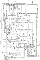
本発明の他の特徴、効果および有利な実施形は、特許請求の範囲と添付の図に基づく本発明の次の説明から明らかになる。図は本発明による燃料電池装置の有利な実施の形態のブロック図である。
【0037】
この燃料電池装置では、アノード12、カソード14および冷却要素16を備えた燃料電池ユニット10のための水素がオートサーミック改質ユニット18によって発生させられる。この改質装置は混合器20、熱交換器22、蒸発器24および触媒改質器26を備えている。水素を発生するために、例えば原料としてのメタノールがメタノールタンク28から、そして水が水タンク30から混合器20に供給される。蒸発器24において、メタノールと水の混合物が蒸発させられ、触媒改質器26において触媒反応で、高い割合の水素を有する生ガス32の形をした反応ガスが発生する。
【0038】
この生ガスは特に一酸化炭素(CO)を含んでいる。この一酸化炭素は燃料電池ユニット10に入る前に除去しなければならない。そのために、生ガス32を酸化ユニット34に案内しなければならない。この酸化ユニットでは、管路36から空気を供給しながら、一酸化炭素が二酸化炭素(CO2 )に酸化されるので、20ppmより小さなCO含有量となる。同時に、水タンク30から管路44を経て水が供給される。この場合、供給される水は噴射装置46によって酸化ユニット34内に噴射される。これは酸化ユニット34内で反応ガスを同時に冷却することになる。このようにして発生し冷却された清浄ガスから、アノードガス凝縮器40内で、水が除かれる。この水は管路42を経て水タンク30に戻される。続いて、水素の高い含有率を有する清浄ガス38は、燃料電池ユニット10のアノード12に案内される。清浄ガス38は例えば約180〜200°Cの温度の50%のH2 、25%のN2 そして25%のCO2 を含んでいる。アノードガス凝縮器40では、清浄ガスはアノード12に入る前に例えば約85°Cに冷却される。
【0039】
カソード側14において、二段型ねじコンプレッサ50として形成された圧縮機49から、圧縮された空気が管路48を経て燃料電池ユニット10に供給される。すべての空気管路は図1において破線で示してある。これにより、燃料電池ユニットは公知の如く、次の反応
H2 +1/2 O2 → H2O +電気エネルギー
によって電気エネルギーを生じる。この電気エネルギーは電極12,14で取り出され、電動機52に供給可能である。二段型ねじコンプレッサ50は例えばカソード14用の例えば約3バールの第1段54と、アノード12の供給される燃焼ガス、すなわち脱水素清浄ガス38用の3.7バールの第2段56とを含んでいる。ねじコンプレッサ50から更に取り出すことによって管路58を経て、圧縮ガスがアノードガス凝縮器40の後の清浄ガス38に供給される。
【0040】
アノードガス流60には水分離器62が配置されている。この水分離器はアノード排気60から水を分離し、管路64を経て水タンク30に供給する。カソード排気流66には凝縮器68が設けられている。この凝縮器はカソード排気66から水を取り除き、管路70を経て水タンク30に供給する。これにより、プロセスガスのために閉鎖水回路が形成されるので、改質ユニット18内で水素を製造するために多量の水を一緒に運ぶ必要がない。
【0041】
混合器20への空気供給部、アノードガス凝縮器40、水分離器62、凝縮器68およびカソード14への空気供給部48を冷却するために、別個の水回路72が設けられている。この水回路は波形の線で示してある。この別個の水回路72は冷却水容器74、イオン消失器を有する水容器76およびカソード14への空気供給部48と混合器20への空気供給部における熱交換器78,80を備えている。
【0042】
アノード排気流60は触媒バーナー82内を流れる。この触媒バーナー内では、アノード排気60は熱エネルギーを発生しながら更に燃焼する。この熱エネルギーは熱交換器22によって蒸発器24と触媒改質器26に供給され、そこで水素を発生するための触媒反応を維持する。触媒バーナー82には管路84から空気が供給される。水タンク30からの水は、管路86を経て、選択的に触媒バーナー82の過程後のアノード排気60へ供給される。メタノールタンク28から管路88を経て触媒バーナー82にメタノールを選択的に供給可能であるので、アノード排気流60が充分でない場合、例えば燃料電池装置のスタート時に、改質ユニット18のために充分な熱エネルギー発生が保証される。
【0043】
カソード排気流66は別個の水回路72の熱交換器90内で冷却され、続いて両排気流60,66が装置から出る前に、熱交換器92を経てアノード排気流60と熱的に結合される。
【0044】
その際、カソード排気流66は膨張タービン94を経て案内される。この膨張タービンは、二段型コンプレッサ50の手前に入口段として設けられている空気98を吸い込むためのコンプレッサ96と共に、共通の軸100に設けられている。これによって、カソード排気流66に含まれるエネルギーはコンプレッサ96内で空気98を圧縮するために回収される。
【0045】
効率が高く、必要スペースが狭く、装置コストが少なくて済むというこの実施の形態の特別な利点は、自給自足の水回路30,40,42,62,64,68,70と共に、酸化ユニット34で一酸化炭素(CO)を選択的に酸化する際に、二段型コンプレッサ50とオートサーミック改質ユニット18を付加的に冷却する水噴射装置46とを組み合わせることによって生じる。
【図面の簡単な説明】
【図1】 本発明による燃料電池装置の有利な実施の形態のブロック図である。[0001]
The present invention includes a reforming unit for generating hydrogen from an energy carrier, particularly a liquid raw material, while supplying air to operate a fuel cell unit in a subsequent arrangement, and between the reforming unit and the fuel cell unit. In particular, the present invention relates to a fuel cell device as a driving device of an automobile described in the superordinate concept of claim 1 in which an oxidizer for converting carbon monoxide into carbon dioxide is disposed. The invention further provides that hydrogen is generated from the feed while supplying air in the reforming process to operate the fuel cell unit, and carbon monoxide is carbon dioxide after the reforming process and before the fuel cell unit. The invention relates to a method for generating electrical energy by means of a fuel cell device, in particular for a motor vehicle drive, as described in the superordinate concept of
[0002]
A catalytic hydrogen generator is known from EP 0217532. This hydrogen generator generates hydrogen from a mixture of methanol and air in an autothermic reforming unit. In this case, the thermocouple is placed in the reforming unit and the thermocouple is supplied to the methanol and air mixture so that the air supply is reduced as the temperature of the thermocouple location in the reforming unit increases. Affects supply.
[0003]
An advanced version of this device is described in WO 96/00186. In this case, the catalyst is arranged around the inlet tube for the methanol and air mixture so that the methanol and air mixture flows radially through the catalyst.
[0004]
German Patent No. 4345319 and German Patent No. 4329323 disclose a fuel cell current generator. In this case, hydrogen is generated from the mixture of methanol and hydrogen in the reforming unit. This hydrogen is supplied to a fuel cell in a subsequent arrangement for generating electrical energy. In order to generate sufficient reaction heat in the reformer, a portion of the methanol is not added to the mixture of methanol and water, but is burned in an additional burner.
[0005]
German Patent Application Publication No. 19629084 discloses an electric vehicle having a drive battery made of a fuel cell. In this case, the fuel cell is arranged to be cooled by the traveling wind.
[0006]
In the article “Heureka?” On the German technical journal Autotechnik, No. 5/1997,
[0007]
Similar fuel cell devices for automobiles are known from the Japanese periodicals Asia Car Report, article “Alternative Fuel” on Jan. 20, 1998, Vol. 272, pp. 34-39. In this case, a methanol reforming unit is provided to generate hydrogen for the fuel cell. In this case, the water generated during the electrochemical reaction of hydrogen and oxygen is used again for the reforming process. Water and methanol deionized for the reforming process are mixed, evaporated and converted to hydrogen and carbon dioxide at a temperature of 250 ° C. This hydrogen is supplied to a fuel cell, which converts this hydrogen, along with oxygen in the air, into electrical energy and water in a catalytic process. The thermal energy required for the evaporation and reforming process is generated by a catalytic burner connected after the fuel cell. This burner is operated with residual gas from the fuel cell. This gas contains hydrogen. This is because the fuel cell device uses only about 75% of the hydrogen supplied. If not enough residual hydrogen is provided to the catalyst burner, methanol from the fuel tank is used to recover the heat of the reformer. Before the gas generated in the reformer starts to be introduced together with the hydrogen component, this gas is purified by a catalytic reaction. In this case, carbon monoxide is converted to carbon dioxide. In the illustrated embodiment of a fuel cell device for an automobile, the methanol reformer comprises an evaporator, a reformer and an oxidation unit for carbon monoxide.
[0008]
German patent DE 4322765 discloses a method and device for dynamic output control for vehicles equipped with fuel cells. This fuel cell supplies electrical energy to the electric drive unit. Starting from the required output corresponding to the accelerator pedal position, the air flow rate is calculated. This air flow rate is necessary to prepare the target output by the fuel cell. The rotational speed of the compressor disposed in the intake pipe of the fuel cell is adjusted in accordance with the required air flow.
[0009]
From European Patent No. 0629013, an air supply method and apparatus for a fuel cell device are known. In this case, the process air is compressed by the compressor before entering the fuel cell. After passing through the fuel cell, the exhaust exhaust is reduced through the turbine to recover energy. In this case, the turbine, the compressor and the additional drive motor are arranged on a common shaft. The compressor is formed so that the number of rotations can be changed, and is arranged on a common shaft together with an expander as a turbine for reducing exhaust gas. The use of an expander that alters the absorption capacity provides air flow regulation for the fuel cell.
[0010]
A screw compressor for refrigerators is known from WO 97/16648. This screw compressor has two pump chambers. The outlet of the first pump chamber is connected to the secondary inlet of the second pump chamber.
[0011]
The problem underlying the present invention is of the kind mentioned at the beginning so that it is highly efficient and compact, as well as being economical and environmentally friendly for generating electrical energy, in particular for motor vehicle drives. It is to improve the fuel cell apparatus.
[0012]
This object is achieved according to the invention by a fuel cell device of the above kind having the features as claimed in claim 1 and by a method of the kind having the features as claimed in
[0013]
Therefore, in the case of a fuel cell device, according to the present invention, a two-stage compressor for air is attached to the reforming unit and the fuel cell unit.
[0014]
This has the advantage that the same pressure is provided for the anode and cathode of the fuel cell unit despite the different pipe lengths and the different stages to be passed. This is crucial for the action of the anode and cathode. In order to supply air to the cathode of the fuel cell unit, an air stream with a relatively low pressure, for example about 2.5-3.5 bar, in particular about 3 bar, is taken from the first stage of the compressor, From the second stage of the compressor, which mainly serves the air supply of the reforming
[0015]
Regardless of the absolute height of the selected pressure, the pressure difference between the first stage and the second stage is about 0.5 to 0.9 bar, in particular 0.7 bar.
[0016]
The two-stage compressor or compressor can be formed as a piston compressor, screw compressor or screw compressor or centrifugal compressor.
[0017]
In order to further improve the economy, in particular the required space, a water injection device can be provided in the oxidation device. This water injection device injects water into the oxidizer.
[0018]
This keeps the carbon monoxide away from the process gas exiting the reforming unit, while at the same time sufficient cooling or pre-cooling is achieved by the high proportion of hydrogen components for the fuel cell unit, so that the process gas is costly cooling. This means that the fuel cell unit can be guided without a device or by a cooling device that does not cost much. In addition, the injected water supplies the oxygen necessary for the oxidation of carbon monoxide. At the same time, additional hydrogen is liberated by the oxidation reaction, so that separate oxygen supply for oxidation can be reduced quantitatively, and at the same time, hydrogen enrichment in the oxidizer reduces the size of the fuel cell device. To do. This reduces the required space and device cost of the fuel cell device.
[0019]
In a preferred implementation the reforming unit is material containing raw materials and oxygen, in particular with a mixer for at least one of water and air.
[0020]
A water separator, particularly a condenser, is provided in at least one of the exhaust stream from the cathode of the fuel cell unit and the exhaust stream from the anode of the fuel cell unit , and the condenser separates water including exhaust gas. By supplying a water storage device connected in front of the autothermic reforming unit, a closed water circuit is achieved without having to carry a large amount of water together for the reforming process.
[0021]
In an advantageous embodiment, a separate water circuit is provided, which cools at least one of the water separator, the fuel cell unit, the fuel cell unit cathode air supply and the reforming unit air supply. To do.
[0022]
In order to generate the heat energy required for the reaction in the reforming unit, a catalyst burner is provided, which burns the exhaust from the anode of the fuel cell unit and passes the waste heat through a heat exchanger. Supply to the reforming unit.
[0023]
Alternative heat generation for the reforming unit is achieved by connecting a catalyst burner to a storage vessel for the feedstock.
[0024]
An expander is provided in the exhaust flow of the cathode of the fuel cell unit, a compressor, in particular a two-stage compressor, is provided in the air flow of the fuel cell unit, and the expander and the compressor are arranged on a common shaft, Energy recovery is achieved.
[0025]
The raw material is preferably a substance containing hydrogen, in particular methanol or benzine.
[0026]
In the method of the above type, in the present invention, air is supplied to the fuel cell unit from the first stage of the two-stage compressor, and air is supplied to the reforming unit from the second stage of the compressor.
[0027]
This has the advantage that the same pressure is provided for the anode and cathode of the fuel cell unit despite the different pipe lengths and the different stages to be passed. This is crucial for the action of the anode and cathode. In order to supply air to the cathode of the fuel cell unit, an air stream with a relatively low pressure, for example about 2.5-3.5 bar, in particular about 3 bar, is taken from the first stage of the compressor, From the second stage of the compressor, which mainly serves the air supply of the reforming
[0028]
In order to improve the economy, especially the required space, a water injection device for injecting water is provided in the oxidation device.
[0029]
This keeps the carbon monoxide away from the process gas exiting the reforming unit, while at the same time sufficient cooling or pre-cooling is achieved by the high proportion of hydrogen components for the fuel cell unit, so that the process gas is costly cooling. This means that the fuel cell unit can be guided without a device or by a cooling device that does not cost much. In addition, the injected water supplies the oxygen necessary for the oxidation of carbon monoxide. At the same time, additional hydrogen is liberated by the oxidation reaction, so that the separate oxygen supply for the oxidation can be reduced quantitatively, and at the same time , the proportion of hydrogen in the process gas increases, The hydrogen enrichment inside makes the fuel cell device smaller. This reduces the required space and device cost of the fuel cell device.
[0030]
In order to increase the efficiency of water supply, water is injected in the form of vapor or aerosol.
[0031]
At least one of the cathode process gas and the fuel cell unit between the oxide and the fuel cell unit of carbon monoxide, by compressed air is supplied, additional efficiency increase of the fuel cell unit is achieved Is possible.
[0032]
Water is separated from at least one of the exhaust stream from the cathode of the fuel cell unit and / or the exhaust stream from the anode of the fuel cell unit and supplied to the reforming process, so that a large amount of water for the reforming process is obtained. A closed water circuit is achievable without having to carry them together.
[0033]
In order to generate the thermal energy necessary for the reaction of the reforming process, the exhaust from the anode of the fuel cell unit is burned and the waste heat is supplied to the reforming process.
[0034]
An alternative heat generation for the reforming process is achieved by burning the feedstock and supplying its thermal energy to the reforming process.
[0035]
Preferably, substances containing hydrogen, in particular methanol or benzine, are used as raw materials.
[0036]
Other features, advantages and advantageous embodiments of the invention will become apparent from the following description of the invention based on the claims and the accompanying drawings. The figure is a block diagram of an advantageous embodiment of a fuel cell device according to the invention.
[0037]
In this fuel cell apparatus, hydrogen for the fuel cell unit 10 including the anode 12, the
[0038]
This raw gas particularly contains carbon monoxide (CO). This carbon monoxide must be removed before entering the fuel cell unit 10. For this purpose, the
[0039]
On the
[0040]
A water separator 62 is disposed in the
[0041]
A
[0042]
The
[0043]
Cathode exhaust stream 66 is cooled in heat exchanger 90 of a
[0044]
In so doing, the cathode exhaust stream 66 is guided through an expansion turbine 94. This expansion turbine is provided on a
[0045]
The special advantages of this embodiment of high efficiency, small space requirements and low equipment costs are the advantages of the
[Brief description of the drawings]
FIG. 1 is a block diagram of an advantageous embodiment of a fuel cell device according to the present invention.
Claims (22)
空気用二段型圧縮機(49)が、燃料電池ユニット(10)のカソード(14)の空気供給のための第1段(54)と、改質ユニット(18)の空気供給のための、前記第1段より高圧の第2段(56)とを備え、これら第1段と第2段の圧力差が前記改質ユニット(18)から前記酸化装置(34)を経て前記燃料電池ユニット(10)へ至る管路での圧力損失に相当し、
前記空気用二段型圧縮機(49)が、前記燃料電池ユニット(10)におけるアノードとカソードの圧力が同じになるよう、改質ユニット(18)と燃料電池ユニット(10)に付設されていることを特徴とする燃料電池装置。While supplying air to drive the subsequent placement of the fuel cell unit (10) includes a reforming unit for generating energy responsible body or al hydrogen (18), a fuel cell the reforming unit (18) during the unit (10), the fuel cell apparatus oxidizer (34) that are arranged for converting carbon monoxide to carbon dioxide,
A two-stage air compressor (49) is provided for supplying air to the cathode (14) of the fuel cell unit (10), and for supplying air to the reforming unit (18). A second stage (56) having a pressure higher than that of the first stage, and the difference in pressure between the first stage and the second stage passes from the reforming unit (18) through the oxidizer (34) to the fuel cell unit ( 10) corresponds to the pressure loss in the pipeline leading to
The two-stage air compressor (49) is attached to the reforming unit (18) and the fuel cell unit (10) so that the anode and cathode pressures in the fuel cell unit (10) are the same . A fuel cell device.
前記燃料電池ユニットにおけるアノードとカソードの圧力が同じになるように、二段型圧縮機の第1段から空気が燃料電池ユニットに供給され、該第1段よりも高圧の前記二段型圧縮機の第2段から空気が改質ユニットに供給されることを特徴とする方法。To operate the fuel cell unit, hydrogen is generated from the feed while supplying air in the reforming process, and carbon monoxide is oxidized to carbon dioxide after the reforming process and before the fuel cell unit . a method for generating electrical energy by fuel cell device,
Air is supplied to the fuel cell unit from the first stage of the two-stage compressor so that the anode and cathode pressures in the fuel cell unit are the same, and the two-stage compressor having a pressure higher than that of the first stage. The air is supplied to the reforming unit from the second stage.
Applications Claiming Priority (3)
| Application Number | Priority Date | Filing Date | Title |
|---|---|---|---|
| DE19822689.6 | 1998-05-20 | ||
| DE19822689A DE19822689A1 (en) | 1998-05-20 | 1998-05-20 | Fuel cell system, especially as drive system of motor vehicle |
| PCT/EP1999/003375 WO1999060646A1 (en) | 1998-05-20 | 1999-05-17 | Fuel cell system and method for producing electric energy using a fuel cell system |
Publications (3)
| Publication Number | Publication Date |
|---|---|
| JP2002516468A JP2002516468A (en) | 2002-06-04 |
| JP2002516468A5 JP2002516468A5 (en) | 2006-07-06 |
| JP4594523B2 true JP4594523B2 (en) | 2010-12-08 |
Family
ID=7868448
Family Applications (1)
| Application Number | Title | Priority Date | Filing Date |
|---|---|---|---|
| JP2000550166A Expired - Fee Related JP4594523B2 (en) | 1998-05-20 | 1999-05-17 | Fuel cell device and method of generating electrical energy by fuel cell device |
Country Status (8)
| Country | Link |
|---|---|
| US (1) | US7045232B1 (en) |
| EP (1) | EP1082773B1 (en) |
| JP (1) | JP4594523B2 (en) |
| KR (1) | KR20010025047A (en) |
| CN (1) | CN1161856C (en) |
| DE (2) | DE19822689A1 (en) |
| TW (1) | TW442997B (en) |
| WO (1) | WO1999060646A1 (en) |
Families Citing this family (28)
| Publication number | Priority date | Publication date | Assignee | Title |
|---|---|---|---|---|
| DE19822691A1 (en) * | 1998-05-20 | 1999-11-25 | Volkswagen Ag | Fuel cell system for a vehicle |
| DE19923738C2 (en) | 1999-05-22 | 2001-08-09 | Daimler Chrysler Ag | Fuel cell system and method for operating a fuel cell system |
| DE19958830B4 (en) * | 1999-11-30 | 2005-09-22 | P21 - Power For The 21St Century Gmbh | Fuel cell system and its use |
| DE10029481C2 (en) * | 2000-06-15 | 2002-06-13 | Mannesmann Ag | Device for supplying fuel into the fuel cell of a fuel cell system and fuel cell system |
| DE10037825A1 (en) | 2000-08-03 | 2002-05-16 | Xcellsis Gmbh | The fuel cell system |
| DE10120947A1 (en) * | 2001-04-22 | 2002-10-24 | Daimler Chrysler Ag | Fuel cell air supply device has electrically-driven low-pressure compressor in series with high-pressure compressor with turbine for energy recovery |
| DE10141903A1 (en) * | 2001-08-28 | 2003-03-27 | Ballard Power Systems | Apparatus for supplying a fuel cell system with an oxygen-containing medium |
| DE10147680A1 (en) * | 2001-09-27 | 2003-04-10 | Ballard Power Systems | Fuel cell system comprises dosing arrangement for introducing starting material into liquid arranged between separator and valve arrangement, and further dosing arrangement and sensor for starting material |
| US20030203264A1 (en) * | 2002-04-24 | 2003-10-30 | Parthasarathy Seshadri | Maximizing PEM fuel cell power plant system efficiency at optimum system pressure |
| KR100481599B1 (en) * | 2002-11-06 | 2005-04-08 | (주)앤틀 | Fuel cell system |
| CA2448715C (en) * | 2002-11-11 | 2011-07-05 | Nippon Telegraph And Telephone Corporation | Fuel cell power generating system with two fuel cells of different types and method of controlling the same |
| DE10254842A1 (en) * | 2002-11-25 | 2004-06-03 | Robert Bosch Gmbh | fuel cell plant |
| ITMI20030644A1 (en) * | 2003-04-01 | 2004-10-02 | Nuvera Fuel Cells Europ Srl | STACK OF MEMBRANE FUEL CELLS SUPPLIED WITH NON-HUMIDIFIED GAS AND METHOD FOR ITS OPERATION |
| DE10315255A1 (en) * | 2003-04-03 | 2004-10-21 | J. Eberspächer GmbH & Co. KG | Fuel cell system and burner arrangement for a fuel cell system |
| KR100757441B1 (en) * | 2005-09-23 | 2007-09-11 | 엘지전자 주식회사 | Fuel cell system |
| JP5221863B2 (en) * | 2006-10-06 | 2013-06-26 | 株式会社日立製作所 | Fuel cell system |
| JP5285946B2 (en) * | 2007-04-06 | 2013-09-11 | パナソニック株式会社 | Method for operating hydrogen generator and method for operating fuel cell system |
| AT505940B1 (en) * | 2008-02-07 | 2009-05-15 | Vaillant Austria Gmbh | HIGH-TEMPERATURE FUEL CELL SYSTEM WITH EXHAUST GAS RECYCLING |
| CN102201586B (en) * | 2011-04-22 | 2013-12-25 | 爱科腾博(大连)科技有限公司 | Fuel cell system |
| JP5763484B2 (en) * | 2011-09-15 | 2015-08-12 | 本田技研工業株式会社 | Fuel cell system |
| JP6178871B2 (en) * | 2013-02-21 | 2017-08-09 | ローベルト ボツシユ ゲゼルシヤフト ミツト ベシユレンクテル ハフツングRobert Bosch Gmbh | Metal oxygen battery with multistage oxygen compressor |
| US9543625B2 (en) * | 2013-02-21 | 2017-01-10 | Robert Bosch Gmbh | Metal/oxygen battery with multistage oxygen compression |
| US20160093904A1 (en) * | 2013-02-21 | 2016-03-31 | Robert Bosch Gmbh | Secondary battery recuperator system |
| CN103192730B (en) * | 2013-03-01 | 2015-07-08 | 宁波拜特测控技术有限公司 | Locomotive traction power system based on fuel cell |
| DK178844B1 (en) * | 2014-07-16 | 2017-03-20 | Serenergy As | A burner evaporator for a fuel cell system |
| CN107394235B (en) * | 2017-07-13 | 2023-06-30 | 上海重塑能源科技有限公司 | Fuel cell auxiliary system |
| CN108110279B (en) * | 2017-11-20 | 2020-09-01 | 宁波申江科技股份有限公司 | Movable methanol recombination fuel cell system |
| CN114899450A (en) * | 2022-04-08 | 2022-08-12 | 海德韦尔(太仓)能源科技有限公司 | Fuel cell system with gas turbine supercharger |
Family Cites Families (24)
| Publication number | Priority date | Publication date | Assignee | Title |
|---|---|---|---|---|
| US4333992A (en) * | 1980-10-30 | 1982-06-08 | United Technologies Corporation | Method for producing steam from the liquid in a moist gas stream |
| US4362788A (en) * | 1981-03-11 | 1982-12-07 | Energy Research Corporation | Fuel cell system with anode and cathodes operating at different pressures |
| GB8521953D0 (en) | 1985-09-04 | 1985-10-09 | Johnson Matthey Plc | Catalytic hydrogen generator |
| US4865926A (en) * | 1988-08-24 | 1989-09-12 | International Fuel Cells Corporation | Hydrogen fuel reforming in a fog cooled fuel cell power plant assembly |
| JPH02183967A (en) * | 1989-01-09 | 1990-07-18 | Ishikawajima Harima Heavy Ind Co Ltd | Power generating system for fused carbonate type fuel cell |
| DE4032993C1 (en) * | 1990-10-15 | 1992-05-07 | Mannesmann Ag, 4000 Duesseldorf, De | |
| JPH06140065A (en) | 1992-09-08 | 1994-05-20 | Toshiba Corp | Fuel cell power generating system |
| DE4318818C2 (en) * | 1993-06-07 | 1995-05-04 | Daimler Benz Ag | Method and device for providing conditioned process air for air-breathing fuel cell systems |
| DE4322765C1 (en) * | 1993-07-08 | 1994-06-16 | Daimler Benz Ag | Dynamic power regulation system for vehicle electric drive unit - regulates power output delivered by fuel cell using correction of oxidant mass flow rate |
| JPH0757756A (en) | 1993-08-06 | 1995-03-03 | Toshiba Corp | Fuel cell power generation system |
| US5360679A (en) * | 1993-08-20 | 1994-11-01 | Ballard Power Systems Inc. | Hydrocarbon fueled solid polymer fuel cell electric power generation system |
| DE4412451C1 (en) * | 1994-04-12 | 1995-09-28 | Daimler Benz Ag | Arrangement of a drive unit in an electric vehicle |
| GB9412786D0 (en) | 1994-06-24 | 1994-08-17 | Johnson Matthey Plc | Improved reformer |
| DE4425634C1 (en) * | 1994-07-20 | 1995-10-26 | Daimler Benz Ag | Fuel cell dosing control valve positioned in tube between pump and fuel cell |
| DE4446841A1 (en) * | 1994-12-27 | 1996-07-04 | Mtu Friedrichshafen Gmbh | Fuel cell module |
| JP3519828B2 (en) * | 1995-08-30 | 2004-04-19 | 本田技研工業株式会社 | Fuel cell system |
| JP4087443B2 (en) * | 1995-09-11 | 2008-05-21 | シーメンス アクチエンゲゼルシヤフト | Method for operating fuel cell facility and fuel cell facility for carrying out this method |
| DE19648995C2 (en) | 1995-10-05 | 2001-07-26 | Magnet Motor Gmbh | Method for regulating the membrane moisture of a polymer electrolyte fuel cell and polymer electrolyte fuel cell with device for regulating the membrane moisture and fuel cell stack formed therefrom |
| WO1997016648A1 (en) | 1995-11-02 | 1997-05-09 | Aaf-Mcquay Incorporated | Improvements in and relating to single screw compressors |
| TW425722B (en) * | 1995-11-27 | 2001-03-11 | Sumitomo Chemical Co | Group III-V compound semiconductor and light-emitting device |
| DE19544895C1 (en) * | 1995-12-01 | 1997-02-27 | Daimler Benz Ag | Oxidising carbon mon:oxide in gas mixt. from hydrocarbon reforming plant |
| DE19545186A1 (en) * | 1995-12-04 | 1997-06-05 | Siemens Ag | Method for operating a high-temperature fuel cell system and high-temperature fuel cell system |
| DE19629084C2 (en) | 1996-07-18 | 1998-07-16 | Siemens Ag | Fuel cell system as a drive battery for an electric vehicle and method for operating such a fuel cell system |
| US6283723B1 (en) * | 1997-01-27 | 2001-09-04 | Vairex Corporation | Integrated compressor expander apparatus |
-
1998
- 1998-05-20 DE DE19822689A patent/DE19822689A1/en not_active Withdrawn
-
1999
- 1999-05-17 JP JP2000550166A patent/JP4594523B2/en not_active Expired - Fee Related
- 1999-05-17 CN CNB998064025A patent/CN1161856C/en not_active Expired - Lifetime
- 1999-05-17 WO PCT/EP1999/003375 patent/WO1999060646A1/en not_active Application Discontinuation
- 1999-05-17 EP EP99924988A patent/EP1082773B1/en not_active Expired - Lifetime
- 1999-05-17 DE DE59904539T patent/DE59904539D1/en not_active Expired - Lifetime
- 1999-05-17 KR KR1020007012984A patent/KR20010025047A/en not_active Application Discontinuation
- 1999-05-17 US US09/701,064 patent/US7045232B1/en not_active Expired - Lifetime
- 1999-11-26 TW TW088108426A patent/TW442997B/en not_active IP Right Cessation
Also Published As
| Publication number | Publication date |
|---|---|
| TW442997B (en) | 2001-06-23 |
| JP2002516468A (en) | 2002-06-04 |
| WO1999060646A1 (en) | 1999-11-25 |
| KR20010025047A (en) | 2001-03-26 |
| EP1082773B1 (en) | 2003-03-12 |
| CN1301407A (en) | 2001-06-27 |
| CN1161856C (en) | 2004-08-11 |
| EP1082773A1 (en) | 2001-03-14 |
| DE59904539D1 (en) | 2003-04-17 |
| US7045232B1 (en) | 2006-05-16 |
| DE19822689A1 (en) | 1999-11-25 |
Similar Documents
| Publication | Publication Date | Title |
|---|---|---|
| JP4594523B2 (en) | Fuel cell device and method of generating electrical energy by fuel cell device | |
| US20070292727A1 (en) | Fuel Cell System and Method for Generating Electrical Energy Using a Fuel Cell System | |
| US6423435B1 (en) | Fuel cell system with an assigned hydrogen generating arrangement | |
| JP4081238B2 (en) | Production of electrical energy from natural gas using solid oxide fuel cells | |
| US6311650B1 (en) | Vehicle having a driving internal-combustion engine and having a fuel cell system for the power supply to electric consuming devices of the vehicle and method for operating such a vehicle | |
| US20030121481A1 (en) | Fuel system | |
| US20020055024A1 (en) | Cogeneration system for a fuel cell | |
| US20020004152A1 (en) | Joint-cycle high-efficiency fuel cell system with power generating turbine | |
| WO2002021624A1 (en) | Thermoelectric reformer fuel cell process | |
| JP5085847B2 (en) | High-efficiency fuel cell power generation system with an expander for power generation | |
| CN1298319A (en) | Process gas purification and fuel cell system | |
| EP1399984A1 (en) | Zero/low emission and co-production energy supply station | |
| JP2010129286A (en) | Power generation system | |
| US6893754B2 (en) | Fuel cell system with device for water recovery and method of operating such a system | |
| JPH1126004A (en) | Power generating system | |
| US20010028968A1 (en) | Fuel cell system and method of operating same | |
| US6667122B2 (en) | Fuel cell system having a heat exchanger | |
| JPH05129029A (en) | Power generation system formed by using fuel cell | |
| JP2662298B2 (en) | Power plant with carbon dioxide separator | |
| US20090246568A1 (en) | System for the generation of electric power on-board a motor vehicle which is equipped with a fuel cell and associated method | |
| JP2006344592A (en) | Fuel cell system and auxiliary method for manufacturing water for fuel cell system | |
| US7722971B2 (en) | Electric generator for motor vehicle | |
| JP2002050371A (en) | Fuel cell system | |
| JP2000095505A (en) | Production of hydrogen and equipment therefor |
Legal Events
| Date | Code | Title | Description |
|---|---|---|---|
| A521 | Written amendment |
Free format text: JAPANESE INTERMEDIATE CODE: A523 Effective date: 20060516 |
|
| A621 | Written request for application examination |
Free format text: JAPANESE INTERMEDIATE CODE: A621 Effective date: 20060516 |
|
| A711 | Notification of change in applicant |
Free format text: JAPANESE INTERMEDIATE CODE: A711 Effective date: 20060830 |
|
| A521 | Written amendment |
Free format text: JAPANESE INTERMEDIATE CODE: A821 Effective date: 20060830 |
|
| A131 | Notification of reasons for refusal |
Free format text: JAPANESE INTERMEDIATE CODE: A131 Effective date: 20091124 |
|
| A601 | Written request for extension of time |
Free format text: JAPANESE INTERMEDIATE CODE: A601 Effective date: 20100223 |
|
| A602 | Written permission of extension of time |
Free format text: JAPANESE INTERMEDIATE CODE: A602 Effective date: 20100302 |
|
| A601 | Written request for extension of time |
Free format text: JAPANESE INTERMEDIATE CODE: A601 Effective date: 20100323 |
|
| A602 | Written permission of extension of time |
Free format text: JAPANESE INTERMEDIATE CODE: A602 Effective date: 20100330 |
|
| A521 | Written amendment |
Free format text: JAPANESE INTERMEDIATE CODE: A523 Effective date: 20100413 |
|
| RD04 | Notification of resignation of power of attorney |
Free format text: JAPANESE INTERMEDIATE CODE: A7424 Effective date: 20100525 |
|
| TRDD | Decision of grant or rejection written | ||
| A01 | Written decision to grant a patent or to grant a registration (utility model) |
Free format text: JAPANESE INTERMEDIATE CODE: A01 Effective date: 20100720 |
|
| A01 | Written decision to grant a patent or to grant a registration (utility model) |
Free format text: JAPANESE INTERMEDIATE CODE: A01 |
|
| A601 | Written request for extension of time |
Free format text: JAPANESE INTERMEDIATE CODE: A601 Effective date: 20100819 |
|
| A602 | Written permission of extension of time |
Free format text: JAPANESE INTERMEDIATE CODE: A602 Effective date: 20100824 |
|
| A61 | First payment of annual fees (during grant procedure) |
Free format text: JAPANESE INTERMEDIATE CODE: A61 Effective date: 20100917 |
|
| FPAY | Renewal fee payment (event date is renewal date of database) |
Free format text: PAYMENT UNTIL: 20130924 Year of fee payment: 3 |
|
| R150 | Certificate of patent or registration of utility model |
Free format text: JAPANESE INTERMEDIATE CODE: R150 |
|
| S111 | Request for change of ownership or part of ownership |
Free format text: JAPANESE INTERMEDIATE CODE: R313113 |
|
| FPAY | Renewal fee payment (event date is renewal date of database) |
Free format text: PAYMENT UNTIL: 20130924 Year of fee payment: 3 |
|
| R350 | Written notification of registration of transfer |
Free format text: JAPANESE INTERMEDIATE CODE: R350 |
|
| FPAY | Renewal fee payment (event date is renewal date of database) |
Free format text: PAYMENT UNTIL: 20130924 Year of fee payment: 3 |
|
| R250 | Receipt of annual fees |
Free format text: JAPANESE INTERMEDIATE CODE: R250 |
|
| R250 | Receipt of annual fees |
Free format text: JAPANESE INTERMEDIATE CODE: R250 |
|
| R250 | Receipt of annual fees |
Free format text: JAPANESE INTERMEDIATE CODE: R250 |
|
| R250 | Receipt of annual fees |
Free format text: JAPANESE INTERMEDIATE CODE: R250 |
|
| R250 | Receipt of annual fees |
Free format text: JAPANESE INTERMEDIATE CODE: R250 |
|
| LAPS | Cancellation because of no payment of annual fees |