JP4593562B2 - One-period volume control and measurement system, method, and device for respiratory hyperpolarized gas transmission for MRI / NMR - Google Patents
One-period volume control and measurement system, method, and device for respiratory hyperpolarized gas transmission for MRI / NMR Download PDFInfo
- Publication number
- JP4593562B2 JP4593562B2 JP2006513176A JP2006513176A JP4593562B2 JP 4593562 B2 JP4593562 B2 JP 4593562B2 JP 2006513176 A JP2006513176 A JP 2006513176A JP 2006513176 A JP2006513176 A JP 2006513176A JP 4593562 B2 JP4593562 B2 JP 4593562B2
- Authority
- JP
- Japan
- Prior art keywords
- gas
- pressure
- transfer valve
- volume
- mass flow
- Prior art date
- Legal status (The legal status is an assumption and is not a legal conclusion. Google has not performed a legal analysis and makes no representation as to the accuracy of the status listed.)
- Expired - Fee Related
Links
Images


Classifications
-
- A—HUMAN NECESSITIES
- A61—MEDICAL OR VETERINARY SCIENCE; HYGIENE
- A61M—DEVICES FOR INTRODUCING MEDIA INTO, OR ONTO, THE BODY; DEVICES FOR TRANSDUCING BODY MEDIA OR FOR TAKING MEDIA FROM THE BODY; DEVICES FOR PRODUCING OR ENDING SLEEP OR STUPOR
- A61M16/00—Devices for influencing the respiratory system of patients by gas treatment, e.g. mouth-to-mouth respiration; Tracheal tubes
- A61M16/10—Preparation of respiratory gases or vapours
- A61M16/12—Preparation of respiratory gases or vapours by mixing different gases
-
- A—HUMAN NECESSITIES
- A61—MEDICAL OR VETERINARY SCIENCE; HYGIENE
- A61M—DEVICES FOR INTRODUCING MEDIA INTO, OR ONTO, THE BODY; DEVICES FOR TRANSDUCING BODY MEDIA OR FOR TAKING MEDIA FROM THE BODY; DEVICES FOR PRODUCING OR ENDING SLEEP OR STUPOR
- A61M16/00—Devices for influencing the respiratory system of patients by gas treatment, e.g. mouth-to-mouth respiration; Tracheal tubes
- A61M16/08—Bellows; Connecting tubes ; Water traps; Patient circuits
- A61M16/0816—Joints or connectors
- A61M16/0841—Joints or connectors for sampling
- A61M16/0858—Pressure sampling ports
-
- A—HUMAN NECESSITIES
- A61—MEDICAL OR VETERINARY SCIENCE; HYGIENE
- A61M—DEVICES FOR INTRODUCING MEDIA INTO, OR ONTO, THE BODY; DEVICES FOR TRANSDUCING BODY MEDIA OR FOR TAKING MEDIA FROM THE BODY; DEVICES FOR PRODUCING OR ENDING SLEEP OR STUPOR
- A61M16/00—Devices for influencing the respiratory system of patients by gas treatment, e.g. mouth-to-mouth respiration; Tracheal tubes
- A61M16/0003—Accessories therefor, e.g. sensors, vibrators, negative pressure
- A61M2016/0015—Accessories therefor, e.g. sensors, vibrators, negative pressure inhalation detectors
- A61M2016/0018—Accessories therefor, e.g. sensors, vibrators, negative pressure inhalation detectors electrical
- A61M2016/0021—Accessories therefor, e.g. sensors, vibrators, negative pressure inhalation detectors electrical with a proportional output signal, e.g. from a thermistor
-
- A—HUMAN NECESSITIES
- A61—MEDICAL OR VETERINARY SCIENCE; HYGIENE
- A61M—DEVICES FOR INTRODUCING MEDIA INTO, OR ONTO, THE BODY; DEVICES FOR TRANSDUCING BODY MEDIA OR FOR TAKING MEDIA FROM THE BODY; DEVICES FOR PRODUCING OR ENDING SLEEP OR STUPOR
- A61M16/00—Devices for influencing the respiratory system of patients by gas treatment, e.g. mouth-to-mouth respiration; Tracheal tubes
- A61M16/0003—Accessories therefor, e.g. sensors, vibrators, negative pressure
- A61M2016/0027—Accessories therefor, e.g. sensors, vibrators, negative pressure pressure meter
-
- A—HUMAN NECESSITIES
- A61—MEDICAL OR VETERINARY SCIENCE; HYGIENE
- A61M—DEVICES FOR INTRODUCING MEDIA INTO, OR ONTO, THE BODY; DEVICES FOR TRANSDUCING BODY MEDIA OR FOR TAKING MEDIA FROM THE BODY; DEVICES FOR PRODUCING OR ENDING SLEEP OR STUPOR
- A61M2202/00—Special media to be introduced, removed or treated
- A61M2202/02—Gases
- A61M2202/0266—Nitrogen (N)
- A61M2202/0275—Nitric oxide [NO]
-
- A—HUMAN NECESSITIES
- A61—MEDICAL OR VETERINARY SCIENCE; HYGIENE
- A61M—DEVICES FOR INTRODUCING MEDIA INTO, OR ONTO, THE BODY; DEVICES FOR TRANSDUCING BODY MEDIA OR FOR TAKING MEDIA FROM THE BODY; DEVICES FOR PRODUCING OR ENDING SLEEP OR STUPOR
- A61M2202/00—Special media to be introduced, removed or treated
- A61M2202/02—Gases
- A61M2202/0291—Xenon
Landscapes
- Health & Medical Sciences (AREA)
- Emergency Medicine (AREA)
- Pulmonology (AREA)
- Engineering & Computer Science (AREA)
- Anesthesiology (AREA)
- Biomedical Technology (AREA)
- Heart & Thoracic Surgery (AREA)
- Hematology (AREA)
- Life Sciences & Earth Sciences (AREA)
- Animal Behavior & Ethology (AREA)
- General Health & Medical Sciences (AREA)
- Public Health (AREA)
- Veterinary Medicine (AREA)
- Magnetic Resonance Imaging Apparatus (AREA)
- Measurement Of The Respiration, Hearing Ability, Form, And Blood Characteristics Of Living Organisms (AREA)
Description
本発明は、NMRスペクトロスコピー及び/または磁気共鳴撮像(「MRI」)を用い
た評価を行うための被検体への偏極済み希ガスの伝達に関する。
The present invention relates to the transmission of polarized noble gases to a subject for evaluation using NMR spectroscopy and / or magnetic resonance imaging (“MRI”).
偏極済みの不活性希ガスによれば、身体内のある種の部位や領域に関して改善されたN
MR信号やMRI画像の作成が可能である。この目的には、偏極済みのヘリウム3(「3
He」)やキセノン129(「129Xe」)などの希ガスが特に適していることが分か
っている。しかしながら、これらの気体の偏極状態は取り扱いや環境条件の影響を受けや
すく、またその偏極状態が望ましくない比較的急激な崩壊を起こす可能性がある。
Polarized inert noble gases provide improved N for certain parts and regions of the body
MR signals and MRI images can be created. For this purpose, polarized helium 3 (" 3
Noble gas such as He ") and xenon 129 (" 129 Xe ") have been found to be particularly suitable. However, the polarization state of these gases is susceptible to handling and environmental conditions, and the polarization state can cause a relatively rapid collapse that is undesirable.
偏極済みの希ガスの生成及び集積のためには過偏極装置が使用される。過偏極装置は、
ある希ガス原子核(129Xeや3Heなど)の偏極を天然レベルまたは平衡レベル(す
なわち、ボルツマン偏極)を超えて人工的に増強させている。こうした増大によってMR
I信号の強度が増強されて増大し、これによって医師が身体内の物質に関するより良好な
画像を得ることができるため、こうした増大は望ましい。その開示を参照によって本明細
書に全面的に示したかのようにしてここに組み込むものとする米国特許第5,545,3
96号、同第5,642,625号、同第5,809,801号、同第6,079,21
3号、及び同第6,295,834号を参照されたい。
A hyperpolarization device is used for the generation and accumulation of polarized rare gases. The hyperpolarizer is
The polarization of certain noble gas nuclei (such as 129 Xe and 3 He) is artificially enhanced beyond the natural or equilibrium level (ie, Boltzmann polarization). With this increase, MR
Such an increase is desirable because the intensity of the I signal is increased and increased, which allows the physician to obtain a better image of the substance in the body. No. 5,545,3, the disclosure of which is hereby incorporated by reference as if set forth fully herein.
No. 96, No. 5,642,625, No. 5,809,801, No. 6,079,21
3 and 6,295,834.
過偏極された気体を生成させるためには、ルビジウム(「Rb」)などの光学ポンピン
グされたアルカリ金属蒸気と希ガスを調合することができる。これら光学ポンピングされ
た金属蒸気は、希ガスの原子核と衝突し、「スピン交換(spin−exchange)
」と呼ばれる現象を通じて希ガスを過偏極させる。アルカリ金属蒸気に対する「光ポンピ
ング(optical pumping)」は、アルカリ金属蒸気に対してそのアルカリ
金属の第1の主共鳴波長(例えば、Rbでは795nm)の円偏向光を照射することによ
って生成される。一般的に述べると、基底状態の原子は励起状態となり、次に引き続いて
崩壊して基底状態まで戻る。適度な磁場(10ガウス)下において、基底状態と励起状態
の間での原子の循環によって、数マイクロ秒でこれら原子の概ね100%の偏極を得るこ
とが可能である。この偏極は一般に、アルカリ金属の単独価電子特性によって実行される
。非ゼロ核スピンの希ガスが存在しているため、相互スピン・フリップ「スピン交換」を
通じて価電子の偏極が希ガス原子核に転移されるようにしてアルカリ金属蒸気の原子が希
ガス原子と衝突することがあり得る。別の偏極増強技法が使用されることもある。
To produce a hyperpolarized gas, an optically pumped alkali metal vapor such as rubidium (“Rb”) and a noble gas can be formulated. These optically pumped metal vapors collide with nuclei of noble gases, and “spin-exchange”
The gas is hyperpolarized through a phenomenon called " “Optical pumping” for the alkali metal vapor is generated by irradiating the alkali metal vapor with circularly polarized light of the first main resonance wavelength of the alkali metal (eg, 795 nm for Rb). Generally speaking, ground state atoms become excited and then decay back to the ground state. Under moderate magnetic fields (10 gauss), it is possible to obtain approximately 100% polarization of these atoms in a few microseconds by circulation of the atoms between the ground and excited states. This polarization is generally performed by the single valence electronic properties of the alkali metal. Since noble gas with non-zero nuclear spin exists, alkali metal vapor atoms collide with noble gas atoms so that valence electron polarization is transferred to noble gas nuclei through mutual spin flip “spin exchange” Can be. Other polarization enhancement techniques may be used.
偏極過程の後、過偏極された気体は、典型的には、非毒性で医薬品として受容可能な生
成物が形成されるように、患者に投与する前にアルカリ金属から分離される(ここでは、
スピン交換技法が使用されている)。しかしながら、生成中及び/または回収中や回収後
において、過偏極気体は比較的急速に劣化または崩壊する(その過偏極状態が失われる)
可能性があり、したがってその取り扱い、回収、輸送、及び保管を慎重にしなければなら
ない。
After the polarization process, the hyperpolarized gas is typically separated from the alkali metal prior to administration to the patient so that a non-toxic and pharmaceutically acceptable product is formed (here. Then
Spin exchange technique is used). However, during production and / or during or after recovery, the hyperpolarized gas deteriorates or collapses relatively quickly (its hyperpolarized state is lost).
Therefore it must be carefully handled, recovered, transported and stored.
従来から幾人かの研究者は、ヘリウムやキセノンなどの過偏極された希ガスを撮像する
ように偏極済み気体を被検体に伝達するための過偏極気体対応の換気器を使用している。
例えば、Hedlundらは、「MR−compatible ventilator
for small animals; computer controlled v
entilation for proton and noble gas imag
ing」(18 Magnetic Resonance Imaging、753〜7
59ページ(2000))において、自身の実験室では換気器が多年にわたってルーチン
で使用されていると述べている。さらに、Hedlundらによる「Three−dim
ensional MR microscopy of pulmonary dyna
mics」(Society of Magnetic Resonance(New
York、NY、1996))、並びにHedlundらがAmer. Thoraci
c Society 1998 International Meeting(Chi
cago、1998)において提示した「MRI of pulmonary airw
ays with hyperpolarized helium; a comput
er−controlled ventilator for imaging syn
chronous gas delivery in animal studies」
(換気器テクノロジーを記述している)と題するポスターも参照されたい。さらに、Bl
ack及び共同研究者らは、過偏極気体対応の換気器を使用して、モルモットの肺内の過
偏極された3Heに関して史上初のインビボ画像とされる画像を作成した。Blackら
による「In vivo He−3 MR images of guinea pig
lungs」(Radiology、199(3)、867〜870ページ(1996
))を参照されたい。過偏極された気体や別の呼吸気体を分配するように変更できる周知
の市販の小動物換気器のうちの1つは、CWE Inc.(Ardmore、Penns
ylvania)がModel SAR−830として市販しているものである。
Traditionally, some researchers have used hyperpolarized gas-compatible ventilators to transfer the polarized gas to the subject to image hyperpolarized noble gases such as helium and xenon. ing.
For example, Hedlund et al., “MR-compatible ventilator.
for small animals; computer controlled v
entry for proton and noble gas image
ing "(18 Magnetic Resonance Imaging, 753-7
59 (2000)) states that in his laboratory, ventilators have been routinely used for many years. In addition, “Three-dim” by Healdund et al.
national MR microscopy of the pulmonary dyna
Mics "(Society of Magnetic Resonance (New
York, NY, 1996)), and Heldund et al., Amer. Thoraci
c Society 1998 International Meeting (Chi
"CRI, 1998)" MRI of pulsed airw
ays with hyperpolarized helium; a compute
er-controlled ventilator for imaging syn
"chronous gas delivery in animal studies"
See also the poster titled (which describes ventilator technology). In addition, Bl
ack and coworkers using hyperpolarized gas-compatible ventilator to create an image to be the first ever in vivo images with respect 3 He which is hyperpolarized in the lungs of guinea pigs. "In vivo He-3 MR images of guinea pig" by Black et al.
lungs "(Radiology, 199 (3), pages 867-870 (1996).
Refer to)). One of the well-known commercially available small animal ventilators that can be modified to dispense hyperpolarized gas or another breathing gas is CWE Inc. (Ardmore, Penns
ylvania) is commercially available as Model SAR-830.
しかしながら、過偏極気体を伝達するために使用される従来の小動物換気器は、動物に
伝達されるボリュームを正確に決定する方法を提供できていない。一般的に言って、従来
の換気器は、動物の肺に伝達されるボリュームを、システム自体によって伝達されるボリ
ュームから分離して適正に決定することができない。例えば従来式のある種の換気器は、
吸気圧力を制御し被検体に対するフロー出力を時間の経過に伴って平均化することによっ
て推定ボリュームを計算する圧力トランスジューサを備えた流量計を使用することを提唱
している。こうした推定値の変動は望ましくない、特に伝達される偏極済み気体量がわず
かでありかつMRI/NMR信号が伝達される偏極済み気体の量、濃度及び偏極レベルに
依存する場合(例えば、ミリモル濃度レンジを用いた小動物の偏極気体検査の場合など)
において望ましくない。
It proposes to use a flow meter with a pressure transducer that calculates the estimated volume by controlling the inspiratory pressure and averaging the flow output to the subject over time. Such fluctuations in estimates are undesirable, especially where the amount of polarized gas transmitted is small and depends on the amount, concentration and polarization level of polarized gas to which the MRI / NMR signal is transmitted (eg, (For example, polarized gas testing of small animals using the millimolarity range)
Is not desirable.
したがって、動物の肺に伝達される気体量及び/または気体のモル数をより正確に決定
できるシステムが必要とされた状態にある。
Accordingly, there is a need for a system that can more accurately determine the amount of gas and / or moles of gas delivered to the animal's lungs.
本発明の実施形態は、動物伝達箇所において現場で採取された(自動式の)計測値に基
づいて換気分配される偏極済み気体ボリュームを計算できるMRI対応の改良型過偏極気
体伝達システム、方法、及びコンピュータ・プログラム成果物を提供することができ、こ
れにより:(a)既知のまたは計算される吸気または気体の1周期ボリューム(tida
l volume)、(b)自動制御式のボリューム伝達、(c)圧力及びボリューム・
パラメータに基づいた現場での流量のリアルタイムまたは動的調整、並びに(d)少なく
とも1つの過偏極気体を含んだ調合気体または選択可能な呼吸気体を提供するための制御
式の換気、のうちの1つまたは複数を提供することができる。
Embodiments of the present invention include an improved hyperpolarized gas delivery system for MRI that can calculate a polarized gas volume that is ventilated and distributed based on (automated) measurements taken in the field at an animal delivery location, A method and computer program product may be provided, whereby: (a) a known or calculated one-cycle volume of inspiration or gas (tida)
l volume), (b) automatically controlled volume transmission, (c) pressure and volume
Real-time or dynamic adjustment of the on-site flow rate based on parameters, and (d) controlled ventilation to provide a blended gas or selectable breathing gas containing at least one hyperpolarized gas, One or more can be provided.
本発明のある種の実施形態は、計測/計算の間に定常状態が維持されるように(すなわ
ち、流入=流出)フローを調整するために流入及び流出圧力を自動的にモニタリングでき
るフィードバック圧力または流量制御システムを含む。したがって、本発明の実施形態は
、システムと関連付けされたパラメータの現場での自動式評価に基づいて、該システムを
気体伝達バルブの上流側において実質的に一定の圧力に維持することができる。
Certain embodiments of the present invention provide feedback pressures that can automatically monitor inflow and outflow pressures to adjust the flow so that steady state is maintained during measurement / calculation (ie, inflow = outflow). Includes flow control system. Thus, embodiments of the present invention can maintain the system at a substantially constant pressure upstream of the gas transfer valve based on an on-site automated evaluation of parameters associated with the system.
本発明の具体的な実施形態は、偏極済み気体または気体調合の制御式伝達に関して定常
状態圧力を提供するためにチューニング可能なキャパシタンス・システムを備えるように
構成されている。このキャパシタンスは、システムのフロー経路に付加される、または該
フロー経路から差し引かれる流体を伴うチューニング・キャパシターの役割をする流体を
満たしたシリンジによって提供することができる。
Specific embodiments of the present invention are configured to include a capacitance system that can be tuned to provide a steady state pressure for controlled transmission of polarized gas or gas blend. This capacitance can be provided by a fluid-filled syringe that acts as a tuning capacitor with the fluid added to or subtracted from the flow path of the system.
吸気圧力を設定して既知のボリュームの伝達が可能であり、かつ/または吸気ボリュー
ムを設定して既知の圧力の伝達が可能である。
A known volume can be transmitted by setting the intake pressure and / or a known pressure can be transmitted by setting the intake volume.
本発明のある種の実施形態は、被検体を換気するための換気フロー経路を有する換気器
システムを目標としている。本システムは、(a)マスフロー制御装置(mass fl
ow controller)と、(b)このマスフロー制御装置と連絡すると共に複数
種の気体を被検体に選択的に分配するように構成された気体伝達バルブと、(c)気体伝
達バルブと流体連絡する第1の気体源と、(d)気体伝達バルブと流体連絡する第2の気
体源と、(e)気体伝達バルブの上流側に配置された第1の圧力センサと、(f)気体伝
達バルブの下流側に配置された第2の圧力センサと、(g)第1及び第2の圧力センサ並
びにマスフロー制御装置と動作可能に関連付けされた制御装置であって、第1及び第2の
圧力センサによって計測された圧力並びにマスフロー制御装置の流量をモニタリングし、
第1の圧力が実質的に定常状態にあるときのマスフロー制御装置の流量の読み値を使用し
て伝達される1周期ボリュームを自動的に決定するように構成された制御装置と、を含ん
でいる。
Certain embodiments of the present invention are directed to a ventilator system having a ventilation flow path for ventilating a subject. This system consists of (a) mass flow controller (mass fl
ow controller), (b) a gas transfer valve configured to communicate with the mass flow controller and selectively distribute a plurality of gases to the subject; 1 gas source, (d) a second gas source in fluid communication with the gas transfer valve, (e) a first pressure sensor disposed upstream of the gas transfer valve, and (f) a gas transfer valve A second pressure sensor disposed downstream; and (g) a control device operably associated with the first and second pressure sensors and the mass flow control device, the first and second pressure sensors Monitor the measured pressure and the flow rate of the mass flow controller,
A controller configured to automatically determine a one-cycle volume transmitted using a flow rate reading of the mass flow controller when the first pressure is in a substantially steady state. Yes.
本システムはさらに気管チューブを含むことができ、またこの制御装置は偏極済み気体
の伝達中に第1の圧力センサの位置に実質的に一定の圧力が発生するようにその流量を調
整するように構成することができる。
The system may further include a tracheal tube, and the controller adjusts the flow rate so that a substantially constant pressure is generated at the position of the first pressure sensor during transmission of the polarized gas. Can be configured.
別の実施形態は、過偏極された気体を被検体に伝達する方法を目標としている。本方法
は、(a)マスフロー制御装置と、気管チューブと、過偏極気体及び少なくとも1つの未
偏極気体を被検体に伝達するように構成された気体伝達バルブと、を備えた換気器システ
ムを設ける工程と、(b)この気体伝達バルブの上流側で換気器システム内の第1の圧力
をモニタリングする工程と、(c)この気体伝達バルブの下流側で換気器システム内の第
2の圧力をモニタリングする工程と、(d)第1の圧力が実質的に一定であるときにマス
フロー制御装置の読み値を取得する工程と、(e)この取得したマスフロー制御装置読み
値を用いて被検体に伝達される過偏極気体の1周期吸気ボリュームを現場で自動的に決定
する工程と、を含む。
Another embodiment is directed to a method of transmitting hyperpolarized gas to a subject. The method includes: (a) a ventilator system comprising: a mass flow controller; a tracheal tube; and a gas transfer valve configured to transmit hyperpolarized gas and at least one unpolarized gas to a subject. (B) monitoring a first pressure in the ventilator system upstream of the gas transfer valve; and (c) a second in the ventilator system downstream of the gas transfer valve. Monitoring the pressure; (d) acquiring a mass flow controller reading when the first pressure is substantially constant; (e) using the acquired mass flow controller reading to Automatically determining on-site a one-cycle inspiratory volume of hyperpolarized gas transmitted to the specimen.
別の実施形態は、過偏極気体を被検体に伝達するためのシステムであって、(a)過偏
極気体及び少なくとも1つの未偏極気体を被検体に伝達するように構成された気体伝達バ
ルブと、(b)気体伝達バルブの上流側に配置されたマスフロー制御装置と、(c)気体
伝達バルブの下流側に配置された気管チューブと、(d)この気体伝達バルブの上流側で
換気器システム内の第1の圧力をモニタリングするための手段と、(e)この気体伝達バ
ルブの下流側で換気器システム内の第2の圧力をモニタリングするための手段と、(f)
マスフロー制御装置の読み値を自動的に取得するための手段と、(g)モニタリングした
第1の圧力及びこの第1の圧力が実質的に一定であるときに取得したマスフロー制御装置
の読み値を用いて被検体に伝達される過偏極気体の1周期吸気ボリュームを現場で自動的
に決定するための手段と、を含んだ伝達システムを目標としている。
Another embodiment is a system for transmitting hyperpolarized gas to a subject, wherein: (a) a gas configured to transmit hyperpolarized gas and at least one unpolarized gas to the subject A transmission valve; (b) a mass flow control device disposed upstream of the gas transmission valve; (c) a tracheal tube disposed downstream of the gas transmission valve; and (d) upstream of the gas transmission valve. Means for monitoring a first pressure in the ventilator system; (e) means for monitoring a second pressure in the ventilator system downstream of the gas transfer valve; and (f).
Means for automatically acquiring a reading of the mass flow controller; and (g) the monitored first pressure and the reading of the mass flow controller acquired when the first pressure is substantially constant. And a means for automatically determining on-site the one-cycle inspiratory volume of the hyperpolarized gas that is used and transmitted to the subject.
ある種の実施形態では、その換気器システムは気体操作バルブの上流側に配置された可
変式マスフロー制御装置を含むことができ、かつその方法は、被検体への過偏極気体の換
気伝達中に実質的に一定の第1の圧力を維持するようにマスフロー制御装置の流量を自動
的に動的調整するように実施することが可能である。
In certain embodiments, the ventilator system can include a variable mass flow controller located upstream of the gas handling valve, and the method can be used during ventilation transmission of hyperpolarized gas to the subject. Can be implemented to automatically dynamically adjust the flow rate of the mass flow controller to maintain a substantially constant first pressure.
このシステム及び/または方法はさらに、所望の1周期ボリュームが選択された状態の
1周期ボリューム動作モードと所望のピーク吸気圧力が選択された状態のピーク吸気圧力
動作モードのいずれかなど所望の動作モードを選択するためのユーザ入力を受け入れるよ
うに動作することが可能である。
The system and / or method further includes a desired mode of operation, such as either a one-cycle volume operating mode with a desired one-cycle volume selected or a peak inspiratory pressure operating mode with a desired peak inspiratory pressure selected. Can be operated to accept user input to select.
さらに別の実施形態は、被検体を換気するための換気フロー経路を有する換気器システ
ムを目標としている。本システムは、(a)複数種の気体を被検体に選択的に分配するよ
うに構成された気体伝達バルブと、(b)気体伝達バルブの上流側に配置されたマスフロ
ー制御装置と、(c)気体伝達バルブと流体連絡する第1の偏極気体源と、(d)気体伝
達バルブと流体連絡する第2の気体源と、(e)気体伝達バルブの上流側に配置された第
1の圧力センサと、(f)気体伝達バルブの下流側に配置された第2の圧力センサと、(
g)気体伝達バルブの上流側に配置された流体チューニング可能なキャパシタンスを有す
るマニホールド・ラインと、を含む。この流体キャパシタンスは、被検体の肺のボリュー
ムに対して少なくとも約10倍大きいボリュームを有している。
Yet another embodiment is directed to a ventilator system having a ventilation flow path for ventilating a subject. The system includes (a) a gas transmission valve configured to selectively distribute a plurality of types of gases to a subject, (b) a mass flow control device disposed upstream of the gas transmission valve, and (c ) A first polarized gas source in fluid communication with the gas transfer valve; (d) a second gas source in fluid communication with the gas transfer valve; and (e) a first gas disposed upstream of the gas transfer valve. A pressure sensor; (f) a second pressure sensor disposed downstream of the gas transfer valve;
g) a manifold line with fluid tunable capacitance located upstream of the gas transfer valve. This fluid capacitance has a volume that is at least about 10 times greater than the volume of the subject's lungs.
本システムは、第1及び第2の圧力センサにより得られた圧力計測値に応答して流体キ
ャパシタンスを調整するためにマニホールドを選択的に係合するように構成させた少なく
とも1つの固定ボリューム・リザーバ(または、ライン)を含むことができる。本システ
ムは、その内部にある量の流体が入ったシリンジであって、マニホールド・ラインと連絡
しており、かつマニホールドに対して流体を選択的に追加または排除するように構成され
ているシリンジを含むことがある。
The system includes at least one fixed volume reservoir configured to selectively engage the manifold to adjust fluid capacitance in response to pressure measurements obtained by the first and second pressure sensors. (Or a line). The system includes a syringe containing an amount of fluid therein, in communication with the manifold line, and configured to selectively add or remove fluid from the manifold. May contain.
上に記載した実施形態に関する動作、特徴、機能及び/または構成のすべて、あるいは
選択された一部は、本発明の企図に応じて、方法、システム、コンピュータ・プログラム
成果物、アセンブリ及び/またはデバイスとして実施されることがある。
All, or selected portions, of the operations, features, functions and / or configurations relating to the above-described embodiments may be selected from methods, systems, computer program products, assemblies and / or devices in accordance with the intent of the present invention. May be implemented.
本発明に関する上述した目的及び態様、並びにその他の目的及び態様についてここで詳
細に説明することにする。
The above objects and aspects of the present invention, as well as other objects and aspects, will now be described in detail.
ここで、本発明の好ましい実施形態を図示している添付の図面を参照しながらこれ以降
で本発明をより十分に説明することにする。しかし、本発明は、多くの異なる形式で具現
化されることがあり、また本明細書に示した実施形態に限定されるものと見なすべきでは
ない。全体を通じて同じ番号は同じ要素を表している。図面では明瞭にするために、層(
layer)、領域、あるいは構成要素を誇張していることがある。これら図面において
破線は、特に記載がない場合、任意選択の特徴を示している。
The present invention will now be described more fully hereinafter with reference to the accompanying drawings, in which preferred embodiments of the invention are shown. However, the present invention may be embodied in many different forms and should not be construed as limited to the embodiments set forth herein. Throughout, the same number represents the same element. For clarity in the drawings, the layers (
layer), regions, or components may be exaggerated. In these drawings, broken lines indicate optional features unless otherwise noted.
本発明の以下に示す説明では、ある構造の別の構造に対する位置的関係を示すためにあ
る決まった用語を利用することがある。本明細書で使用する場合、「前方向(forwa
rd)」やこれに関する派生表現は、標的気体や標的気体混合物が換気器システムを通過
する際に移動する全般的方向を意味しており、この用語は、製造環境において、作用を受
けているある材料がその製造過程内で別の材料と比べてより遠方まで進んでいることを示
すために頻繁に用いられる「下流側(downstream)」という用語と同義語であ
るとする意図である。逆に、「後方向(rearward)」や「上流側(upstre
am)」並びにこれらに関する派生表現は、それぞれ前方向や下流側と反対の方向を意味
している。
In the following description of the invention, certain terminology may be used to indicate the positional relationship of one structure to another structure. As used herein, “forward”
rd) "and related expressions refer to the general direction in which the target gas or target gas mixture moves as it passes through the ventilator system, and this term is acted upon in the manufacturing environment. It is intended to be synonymous with the term “downstream” that is frequently used to indicate that a material has traveled farther in the manufacturing process than another material. Conversely, “rearward” and “upstream”
am) "as well as derivative expressions relating to these means the forward direction and the direction opposite to the downstream side, respectively.
さらに本明細書で記載する場合、偏極済み気体は生成され収集されており、また具体的
な実施形態では、MRI及び/またはNMRスペクトロスコピーの用途において偏極済み
気体は、冷凍され、解凍され、単独で使用されるかかつ/または別の構成成分と組み合わ
せられることがある。さらに本明細書で使用する場合、「偏極済み気体(polariz
ed gas)」という用語は、少なくとも1つの偏極させた関心対象気体(3He及び
/または129Xe(ただし、これらに限らない)など)を含んでおり、また所望により
別の担体、調合気体またはバッファ気体など1つまたは複数の別の構成成分を含むことが
ある。さらに、「偏極する(polarize)」、「偏極装置(polarizer)
」、「偏極済みの(polarized)」その他の用語は、「過偏極する(hyper
polarize)」、「過偏極装置(hyperpolarizer)」、「過偏極済
みの(hyperpolarized)」その他の用語と交換可能に使用されている。
As further described herein, polarized gas is generated and collected, and in specific embodiments, polarized gas is frozen and thawed in MRI and / or NMR spectroscopy applications. May be used alone and / or combined with another component. Further, as used herein, “polarized gas”
The term ed gas) "means at least one polarized so the interest gas (3 the He and / or 129 Xe (where limited not to) includes the like), yet another carrier optionally, formulated gas Or it may contain one or more other components, such as a buffer gas. Furthermore, “polarize”, “polarizer”
"," Polarized "and other terms are" hyperpolarized ".
"polarize", "hyperpolarizer", "hyperpolarized" and other terms are used interchangeably.
本発明により企図される換気器システム及び気体伝達バルブは、任意の被検体に対して
使用することができると共に、NMR及び/またはMRI手順向けに過偏極気体対応とさ
せることができる。本明細書では検討を簡略とするために選択可能な換気気体の伝達に対
する単一の気体伝達バルブとして記載しているが、離散的な複数のバルブが使用されるこ
ともある。本発明に関する「被検体(subject)」は、任意の動物対象とすること
ができると共に、哺乳類(例えば、ヒト、イヌ類、ネコ類、ウシ類、ヤギ類、ヒツジ類、
ウマ類、ゲッシ類、ブタ類、及び/またはウサギ類)であることが好ましい。「小動物(
small animal)」という用語には、マウス、ラット、モルモット、イヌ、ネ
コ、サル、ブタ、及びラビットが含まれる。
Ventilator systems and gas transfer valves contemplated by the present invention can be used for any subject and can be hyperpolarized gas capable for NMR and / or MRI procedures. Although described herein as a single gas transfer valve for selectable ventilation gas transfer for ease of discussion, discrete valves may be used. A “subject” in the context of the present invention can be any animal subject and is a mammal (eg, human, dog, cat, cow, goat, sheep,
Horses, gosses, pigs, and / or rabbits). "Small animals (
The term “small animal” includes mice, rats, guinea pigs, dogs, cats, monkeys, pigs, and rabbits.
偏極済み気体を集積しかつ捕捉するためには様々な技法が利用されてきた。例えば、C
atesらに対する米国特許第5,642,625号は偏極済み希ガスのスピン交換のた
めの大体積過偏極装置について記載しており、またCatesらに対する米国特許第5,
809,801号はスピン偏極した129Xe用の極低温アキュムレータについて記載し
ている。本明細書で使用する場合、「過偏極する」「偏極する」その他の用語は交換可能
に使用されており、ある種の希ガス原子核に対する偏極を天然レベルまたは平衡レベルを
超えて人工的に増強させることを意味している。こうした増大によって、身体の物質や目
標部位に関するより良好なNMRスペクトロスコピー及び/またはMRI画像に対応した
より強力な撮像信号を得ることができるため、こうした増大は望ましい。当業者であれば
周知であるように、過偏極は光学ポンピングされたアルカリ金属蒸気によるスピン交換に
よって、また別法では準安定性交換(metastability exchange)
によって誘導することができる。Albertらによる米国特許第5,545,396号
を参照されたい。
Various techniques have been used to collect and trap the polarized gas. For example, C
US Pat. No. 5,642,625 to ates et al. describes a large volume hyperpolarization device for spin exchange of polarized noble gases, and US Pat.
No. 809,801 describes a spin-polarized 129 Xe cryogenic accumulator. As used herein, the terms “hyperpolarize,” “polarize,” and other terms are used interchangeably to make polarization for certain noble gas nuclei artificially above natural or equilibrium levels. It means to strengthen. Such an increase is desirable because it can result in a better NMR spectroscopy and / or stronger imaging signal corresponding to the MRI image of the body material and target site. As is well known to those skilled in the art, hyperpolarization is achieved by spin exchange with an optically pumped alkali metal vapor, or alternatively by a metastable exchange.
Can be induced by. See US Pat. No. 5,545,396 by Albert et al.
具体的な実施形態では、換気する偏極済み気体は129Xeや3Heなどの希ガスとす
ることができる。別の気体及び/または希ガスが単独であるいは組み合わせて使用される
こともある。さらにバッファ気体の形成は、その内容を参照によって本明細書に全面的に
示したかのようにしてここに組み込むものとする米国特許第6,295,834号に記載
されるようにして使用されることがある。別の実施形態では、その偏極済み気体は、動的
核偏極(dynamic nuclear polarization:DNP)及び/
またはパラ水素誘導偏極(para−hydrogen induced polari
zation)を用いて偏極を受けることがあるような13C濃度を高めた有機物分子な
どの13C及び/または15N化合物を成すことがある。
In a specific embodiment, the polarized gas to be ventilated can be a noble gas such as 129 Xe or 3 He. Other gases and / or noble gases may be used alone or in combination. Further, the formation of buffer gas should be used as described in US Pat. No. 6,295,834, the contents of which are hereby incorporated as if fully set forth herein. There is. In another embodiment, the polarized gas is a dynamic nuclear polarization (DNP) and / or
Or para-hydrogen induced polarization
may form a 13 C and / or 15 N compounds, such as organic molecules such 13 increased the C concentration as may be subjected to polarization using zation).
図1は、本発明の実施形態に従って実行することができる動作を表している。図示のよ
うに、MFC(「マスフロー制御装置」)、気管チューブ、及び過偏極気体と未偏極気体
を(選択的に)伝達するように構成された気体伝達バルブを備えた換気器システムが提供
される(ブロック100)。気体伝達バルブの上流側において換気器システム内の第1の
圧力がモニタリングされる(ブロック102)。気体伝達バルブの下流側において換気器
システム内の第2の圧力がモニタリングされる(ブロック104)。肺に伝達される過偏
極気体の1周期ボリュームは、第1の圧力が実質的に定常状態にあるときのMFCの流量
を用いて現場で自動的に決定することができる(ブロック110)。定常状態とは、圧力
変動が所望の許容誤差内にあり所望の時間間隔内で時間の経過に伴って増減しないことを
意味している。ある種の実施形態では、換気器システムは、過偏極気体の伝達中に実質的
に一定の第1の圧力に維持されるようにMFC流量を動的に自動制御し調整している。本
システムは、ユーザ選択可能な設定1周期ボリューム・モードとPIPモードのどちらで
システムが動作するかに従って、実質的に一定のP1圧力及び/またはMFCから実質的
に一定の流量が選択的に提供されるようにMFC流量を自動的に動的調整することができ
る(ブロック109)。
FIG. 1 depicts operations that can be performed in accordance with an embodiment of the present invention. As shown, a ventilator system comprising an MFC (“Mass Flow Controller”), a tracheal tube, and a gas transfer valve configured to (optionally) transmit hyperpolarized and unpolarized gas. Is provided (block 100). A first pressure in the ventilator system is monitored upstream of the gas transfer valve (block 102). A second pressure in the ventilator system is monitored downstream of the gas transfer valve (block 104). The one-cycle volume of hyperpolarized gas delivered to the lungs can be automatically determined in the field using the flow rate of the MFC when the first pressure is in a substantially steady state (block 110). Steady state means that the pressure fluctuation is within a desired tolerance and does not increase or decrease over time within a desired time interval. In certain embodiments, the ventilator system dynamically automatically controls and adjusts the MFC flow rate to maintain a substantially constant first pressure during hyperpolarized gas transmission. The system selectively provides a substantially constant flow from a substantially constant P1 pressure and / or MFC, depending on whether the system operates in a user selectable set-period volume mode or PIP mode. The MFC flow rate can be automatically dynamically adjusted (block 109).
1つまたは複数の1周期ボリューム(1周期ボリュームは、各呼吸の間におけるボリュ
ーム変化として記述することができる)で伝達される過偏極気体のモル量は、MFCデー
タを用いて決定された1周期ボリュームに基づいて計算し、標準の温度及び圧力になるよ
うに調整することができる(ブロック108)。すなわち、1周期ボリュームは、標準温
度及び圧力において計測することができ、またこの値を標準温度及び圧力におけるこのボ
リュームでのモル値に変換し、これにより被検体の肺に伝達される過偏極気体のモル数の
決定を評価することができる。計測される量は、小動物の換気ではミリモル・レンジとす
ることができる。
The molar amount of hyperpolarized gas delivered in one or more one-cycle volumes (one-cycle volume can be described as a volume change during each breath) was determined using MFC data. Calculations can be made based on the periodic volume and adjusted to a standard temperature and pressure (block 108). That is, a one-cycle volume can be measured at standard temperature and pressure, and this value is converted to a molar value at this volume at standard temperature and pressure, which is transmitted to the subject's lungs. The determination of the number of moles of gas can be evaluated. The amount measured can be in the millimole range for small animal ventilation.
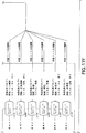
図2A〜Bは本発明の別の実施形態に従って換気器を動作させて過偏極気体を伝達する
ように実施できる動作を表している。上で検討した実施形態と同様に、この換気器伝達シ
ステムは、MFCと、気管チューブと、離間させた第1及び第2の圧力センサ(1つを気
体伝達バルブ及び/または気管チューブの上流側に配置させ、また1つを気体伝達バルブ
の下流側及び/または気管チューブの上または内部に配置させる)と、を含むことができ
る。これらのセンサは、動作時に換気器システム内でそれぞれ第1及び第2の圧力P1、
P2を自動的に計測するように構成することができる。所望の呼吸サイクル、呼吸数及び
/または吸気率(すなわち、毎分の呼吸数「BPM」、並びに吸気/呼気「I/E」比)
を設定することができる(ブロック153)。この気管チューブは、(動作モードの選択
前、選択中、または選択後に)被検体内でその肺と流体連絡するように位置決めすること
ができる(ブロック157)。MFC流量は、実質的に一定のP1が提供されるように調
整することができる(ブロック159)。P1が定常状態にあるときに、PIP(ピーク
吸気圧力)で標準温度及び圧力において換気を受ける被検体の1周期ボリュームを、流量
/頻度=排出ボリューム/サイクル(典型的には、ml/サイクルを単位とする、ただし
別の単位を使用することも可能)を用いて計算する、または決定することができる(ブロ
ック161)。過偏極気体の伝達量は、計算された1周期ボリュームを用いて現場で出力
することができる(ブロック165)。
2A-B represent operations that can be performed to operate a ventilator to transmit hyperpolarized gas in accordance with another embodiment of the present invention. Similar to the embodiments discussed above, this ventilator transmission system includes an MFC, a tracheal tube, and spaced first and second pressure sensors (one upstream of the gas transfer valve and / or tracheal tube). And one on the downstream side of the gas transfer valve and / or on or within the tracheal tube). These sensors are in operation the first and second pressures P1, respectively in the ventilator system.
It can be configured to automatically measure P2. Desired respiration cycle, respiration rate and / or inspiration rate (ie, respiration rate “BPM” per minute, and inspiration / expiration “I / E” ratio)
Can be set (block 153). The tracheal tube can be positioned in fluid communication with the lung within the subject (before, during, or after selection of an operating mode) (block 157). The MFC flow rate can be adjusted to provide a substantially constant P1 (block 159). When P1 is in steady state, PIP (Peak Inspiratory Pressure) is one cycle volume of the subject being ventilated at standard temperature and pressure, Flow / Frequency = Exhaust Volume / Cycle (typically ml / cycle Can be calculated or determined using units (but other units can be used) (block 161). The amount of hyperpolarized gas transfer can be output in-situ using the calculated one-cycle volume (block 165).
気管チューブを含む換気システムの気体フロー経路の所定の部分によって、第1の静的
幾何学ボリューム「V1」が規定される(ブロック152)。動作時において、計算され
た1周期ボリュームV1’から第1の幾何学ボリューム「V1」が差し引かれる(ブロッ
ク154)、これがある特定の1つまたは複数のPIPに関して(各)呼吸中に排出され
る気体のボリュームとなる。ボリューム補正によって、わずかな量もその結果に影響を及
ぼす可能性があるような小動物に伝達される1周期ボリュームに関するより適正な代表値
、すなわち「より正しい(truer)」値を提供することができる。固定の幾何学ボリ
ュームV1は、既知のまたは計測した寸法を用いて計算することや、気管チューブが閉じ
た状態で第1の圧力が安定しているときに動的に決定することができる。
A first static geometry volume “V1” is defined by a predetermined portion of the gas flow path of the ventilation system including the tracheal tube (block 152). In operation, the first geometric volume “V1” is subtracted from the calculated one-cycle volume V1 ′ (block 154), which is expelled during breathing for each particular PIP or PIPs. It becomes the volume of gas. Volume correction can provide a more appropriate representative value for a one-cycle volume, i.e., a "true" value, that is transmitted to small animals where even small amounts can affect the results. . The fixed geometric volume V1 can be calculated using known or measured dimensions or can be determined dynamically when the first pressure is stable with the tracheal tube closed.
具体的な実施形態では、気管チューブの遠位端部分(被検体内の最も深い位置にくるこ
とになる端部)には、被検体内に挿入する前にキャップを付けるか、現場で閉じた状態に
する(ブロック155)。すなわち、V1’は、P1が定常動作状態にあるときのMFC
の値を用いて決定することができる。下流側の幾何学ボリュームは一定である(チューブ
が閉じた状態にある)ため、V1は、PIPと大気圧の間の圧力変化から計算することが
できる。選択された気体は、V1固定の幾何学評価中は既知の流量で伝達させ、第1の圧
力及びピーク吸気圧力(P2において計測)が安定、すなわちPIP中に定常状態となっ
た後に、流入を流出と等しくさせる(すなわち、吸気時のフローを呼気時のフローと等し
くさせる)ことができる(ブロック156)。
In a specific embodiment, the distal end portion of the tracheal tube (the end that will reach the deepest location within the subject) is capped or closed in situ prior to insertion into the subject. A state is entered (block 155). That is, V1 ′ is the MFC when P1 is in a steady operation state.
Can be determined using the value of. Since the downstream geometric volume is constant (the tube is closed), V1 can be calculated from the pressure change between PIP and atmospheric pressure. The selected gas is transmitted at a known flow rate during the V1 fixed geometry evaluation, and the inflow is allowed after the first pressure and peak inspiratory pressure (measured at P2) are stable, ie steady state during PIP. The outflow can be made equal (ie, the inspiratory flow is made equal to the exhaled flow) (block 156).
第1及び第2の圧力をモニタリングしこのデータを用いてシステムの選択された動作パ
ラメータを自動的かつ動的に調整し、これにより所望のピーク吸気圧力に到達させかつ第
1の圧力を安定にすることができる(ブロック160)。この動的調整(複数回のことも
ある)を実施すると、偏極済み気体の伝達中に実質的に一定の第1の圧力を維持すること
ができる(ブロック162)。システムは、ユーザが設定できる選択可能な異なるモード
に従って動作することが可能であり、したがって、本システムは、吸気ボリュームが決定
され(または、計測され)る設定吸気圧力モード、あるいは吸気圧力が計測される設定1
周期(吸気)ボリューム・モード、を用いて動作することが可能である(ブロック166
)。
The first and second pressures are monitored and this data is used to automatically and dynamically adjust selected operating parameters of the system so that the desired peak inspiratory pressure is reached and the first pressure is stabilized. (Block 160). Performing this dynamic adjustment (which may be multiple times) can maintain a substantially constant first pressure during transmission of the polarized gas (block 162). The system can operate according to different selectable modes that can be set by the user, so the system can measure the intake air pressure mode, or the intake air pressure, where the intake volume is determined (or measured).
It is possible to operate using a periodic (intake) volume mode (block 166).
).
いずれの場合にも1周期ボリュームが計測される場合、「総」1周期ボリュームV1’
(気体伝達バルブの下流側のボリュームを主に表す)が計測される。チューブV1のボリ
ューム寄与は、ある特定のPIP時点で差し引かれることがある。中型動物や大型動物で
は、チューブに関するボリューム補正を必要としないことがある。
In any case, when one-cycle volume is measured, the “total” one-cycle volume V1 ′
(Mainly representing the volume downstream of the gas transfer valve) is measured. The volume contribution of tube V1 may be subtracted at a particular PIP time. Medium and large animals may not require volume correction for the tube.
図3Aは、換気器システム10の一実施形態を表している。図示のように、システム1
0は、制御装置15と、可変式マスフロー制御装置(MFC)18と、第1の圧力センサ
21(圧力トランスジューサPT1で示す)と、気体伝達バルブ25と、第2の圧力セン
サ27と、気管チューブ30と、を含んでいる。気体伝達バルブ25は偏極気体源43及
び未偏極気体源43と流体連絡している。ある種の実施形態では、その気体伝達バルブ2
5は、任意選択で、追加的な気体源(本図では機構47で示す)と連絡させることがある
。マスフロー制御装置18は、ニューヨーク州、Orangeburg所在のAALBO
RGから入手できる電圧制御式コントローラp/n DFC2600(商標)など、可変
較正式のマスフロー制御装置とすることができる。
FIG. 3A represents one embodiment of a
0 is a
5 may optionally communicate with an additional gas source (shown as
It can be a variable calibration mass flow controller, such as a voltage controlled controller p / n DFC2600 ™ available from RG.
図3Aにはさらに、動物被検体50で示す被検体に対する流入及び流出の方向(矢印で
表示)も示している。呼息すなわち呼気の間において、排気は被検体を出て気管チューブ
30を通って戻され、通気ポート25vを経由して気体伝達バルブ25から出て行く。通
気ポート25vは呼息される気体の内容、濃度または比を決定する気体センサ(図示せず
)と流体連絡させることがある。
FIG. 3A also shows inflow and outflow directions (indicated by arrows) with respect to the subject indicated by the
一般的に言って、動作時においてマスフロー制御装置18の流量を調整して被検体に対
する所望のボリュームの伝達を制御するために制御フィードバック・システムが使用され
る。このフィードバックは、第1及び第2の圧力センサ21、27のモニタリングされた
圧力読み値に基づいている。第1のセンサ21はマスフロー制御装置18の近傍で気体伝
達バルブ25の上流側に配置されている。第2のセンサ27は動物50の近傍で気体伝達
バルブ25の下流側に配置されている。センサ27は、圧力トランスジューサとすること
や、別のタイプの圧力センサとすることができる。ある種の実施形態では、その第2の圧
力センサ27は、気管内チューブ自体の内部または該チューブ上に位置決めし、センサ2
7を発生源や目的物にできる限り近づけて配置することによって肺内の圧力の計測を可能
とさせることができる。しかし、マウスその他に使用する場合などで気管チューブ直径が
極めて小さい場合などのある特定の実施形態では、そのセンサ27が肺の上流側に位置決
めされることがある。気体伝達バルブには、気管チューブをバルブ本体を通して接続する
ためのポートを追加することができる。
Generally speaking, a control feedback system is used to adjust the flow rate of the
It is possible to measure the pressure in the lung by arranging 7 as close as possible to the source and the object. However, in certain embodiments, such as when used for mice and others, such as when the tracheal tube diameter is very small, the
ある状況では「流入=流出」という動作前提を使用することができる。この流入とは、
気体フロー経路の気体伝達バルブの上流側ボリューム内へのMFCからのフローを意味し
ており、またこの流出は、気体伝達バルブの下流側のボリュームを出るフローを意味して
いる。第1のセンサ21における圧力が換気中に増加し続ける場合、その流量が過大とな
り制御装置15によってそのフローを動的に低減させることがあり得る。第1のセンサ2
1における圧力が換気中に低下すると、追加的なフローが必要となり制御装置15によっ
てそのフローを動的に増加させることがあり得る。第1及び/または第2のセンサ21、
27における圧力がピーク吸気圧力計算の間に定常状態に達すると、適正フローの使用状
態となる。
In some situations, the operating assumption “inflow = outflow” can be used. This inflow is
It means the flow from the MFC into the upstream volume of the gas transfer valve in the gas flow path, and this outflow means the flow leaving the volume downstream of the gas transfer valve. If the pressure at the
As the pressure at 1 drops during ventilation, an additional flow is needed and the
When the pressure at 27 reaches a steady state during peak intake pressure calculation, the proper flow is in use.
マスフロー制御装置18の読み値は、標準の大気圧(1ATM、14.7psia、1
033.51cmH2O)及び温度(70°F)にある較正気体に基づいている。温度及
び圧力をモニタリングし、適宜調整する(標準の大気圧及び温度に対して正規化した読み
値とする)ことができる。当初の、すなわち「第1パスの」動作設定または評価では、温
度の影響はわずかであると見なすことができる。較正気体が出力に使用する気体でない場
合、フロー設定点を決定するために変換定数を適用することができる。例えば、マスフロ
ー制御装置18が窒素に対して較正されており、一方使用するのがヘリウムであれば、そ
の計算に変換係数1.454が使用される。表1は、換気器の動作に使用されるパラメー
タを計算する際に使用できるデフォルト設定(標準の温度及び圧力)に関する変換「K」
係数の例を一覧表示したものである。
The reading of
033.51 cmH 2 O) and temperature (70 ° F.). Temperature and pressure can be monitored and adjusted accordingly (with readings normalized to standard atmospheric pressure and temperature). In the initial or “first pass” operating setup or evaluation, the temperature effect can be considered to be minimal. If the calibration gas is not the gas used for output, a conversion constant can be applied to determine the flow set point. For example, if the
Examples of coefficients are listed.

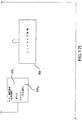
図3Bは、較正ボリュームVcとしても記載可能な(また、以下においてVcalと記
載することがあるような)第1の固定システム・ボリューム「V1」を規定するように、
システム10に取り付ける間に気管チューブ30の出口側端部を閉じるために気管チュー
ブ30にキャップ(端部キャップ30cで示す)を付けて(キャップ、バルブまたは別の
手段により)閉じた気管チューブ30を付けた被検体の外部に配置させたときに較正圧力
P1を確立できることを表している。この較正ボリュームVcは、換気器システムの気体
フロー経路のうち図3Aに示すような固定の幾何学構成を有する所定の部分と関連付けさ
せている。典型的には、較正ボリュームVcは、気体伝達バルブ25の一部分を通って気
管チューブ30の遠位端30dまで延びる長さ「L」を有する気体フロー経路の当該部分
となる。この長さは約12インチとすることがある。気管内チューブ30は、雄型ルアー
ロック(図示せず)を介してバルブ25に解放可能に接続できる1/16インチ内径の細
管から形成させることがある。図3Bは、複数の個別選択可能な気体バルブ251、25
2、253を備えた気体伝達バルブ25の一実施形態を表している。固定ボリュームV1
は、この実施形態では、フロー経路のクロスハッチ部分で示したボリュームであり、バル
ブ253の下流側すなわちバルブ253の先側に気管チューブ30の遠位端30dまで前
進入力フロー方向で延びるフロー経路を含んでおり、また圧力トランスジューサ27まで
の接続、排出方向すなわち出力方向で、気管チューブから通気ポート25vと関連付けさ
れたバルブ254までの接続を含んでいる。
FIG. 3B defines a first fixed system volume “V1” that can also be described as calibration volume Vc (and may also be referred to as Vcal in the following).
The closed
1 represents an embodiment of a
Flow, in this embodiment, a volume indicated by cross-hatched portion of the flow path, which extends in the forward input flow direction on the front side of the downstream side, that
気管チューブ30を被検体の肺と流体連絡させた状態にして動作位置に配置させると、
肺が呼吸中に変化する関連する1周期ボリュームを有し、このボリュームが第1のシステ
ム・ボリュームV1に追加されて総1周期ボリュームV1’が提供される。図4は、この
ボリュームの換気器システム10への追加を表したグラフである。すなわち、圧力フィー
ドバック制御システムがないため、気管チューブ30を開いて肺内に置いた状態としたよ
り大きくなったリザーバ・ボリュームに対しても、システム10は同じ流量で伝達してお
り、これが圧力を低下させることになる(図4でV2を追加したときで示した圧力の低下
によって表している)。しかし、この流量は増加させてシステム10を所望の実質的に一
定の圧力に再度至らせる(あるいは、維持する)ことができる。これを図4では、肺がシ
ステムに追加された状態(気管チューブを開いた状態で被検体内の適所に置いたとき)で
も圧力がP1値まで戻り横ばいになるように表している。
When the
The lung has an associated one-cycle volume that changes during breathing, and this volume is added to the first system volume V1 to provide a total one-cycle volume V1 ′. FIG. 4 is a graph showing the addition of this volume to the
図5A及び5Bは、気管チューブ30を被検体内の適所に置いた状態の動作時における
第1のセンサ21の位置における圧力P1を、第2のセンサ27の位置における圧力と関
連させて時間(t)の経過に従って表している。第2のセンサ27の位置における圧力P
2は、動作時において被検体の気道内で発生しており、選択したBPM及びI/E比に対
応する。このP2圧力の最大値がピーク吸気圧力(PIP)である。図5Aは、計測誤差
を生じさせる可能性がある第1の圧力の圧力変動を表している。図5Bは、システム10
が、実質的に一定の動作圧力すなわちシステム圧力P1を、本発明の実施形態に従ってP
1が定常状態または安定状態(時間の経過と共に上昇したり低下したりしない)にありか
つPIPと実質的に等しい及び/またはPIPより大きいようにして提供するように制御
されていることを表している。ある種の実施形態では、このP1圧力の安定性は、気体伝
達バルブの上流側に配置させたキャパシタンス・ボリューム(これについては、以下でさ
らに検討することにする)を用いて実施することができる。このキャパシタンスの大きさ
は、図5Aに示したP1の変動を低下させて、P1が図5Bに示したのとより近い挙動に
なるようにチューニングすることができる。キャパシタンスが過大になるとシステムの応
答が遅くなることに留意されたい。
5A and 5B show that the pressure P1 at the position of the
2 occurs in the airway of the subject during operation and corresponds to the selected BPM and I / E ratio. The maximum value of this P2 pressure is the peak intake pressure (PIP). FIG. 5A represents the pressure variation of the first pressure that can cause a measurement error. FIG. 5B illustrates the
Is substantially constant operating pressure or system pressure P1 according to an embodiment of the present invention.
1 is in a steady state or stable state (does not increase or decrease over time) and is controlled to provide substantially equal to and / or greater than PIP Yes. In certain embodiments, this P1 pressure stability can be implemented using a capacitance volume (which will be discussed further below) located upstream of the gas transfer valve. . The magnitude of this capacitance can be tuned to reduce the variation of P1 shown in FIG. 5A so that P1 behaves more like that shown in FIG. 5B. Note that excessive capacitance slows down the response of the system.
図3Aに戻ると、ある種の実施形態では、第1のセンサ21は、マスフロー制御装置1
8と気体伝達バルブ25の間におけるシステム10の圧力を気体伝達バルブ25への流入
に基づいてモニタリングするために使用される圧力トランスジューサPT1とすることが
できる。第2のセンサ27もまた圧力トランスジューサPT2とすることができ、被検体
(動物とすることが可能)からの気道圧力のモニタリングのために使用することができる
。気体伝達バルブ25は、被検体に空気を供給すること、または被検体に呼吸または呼息
の保持を可能とすることのいずれか、あるいはこの両方を行うように構成させることがで
きる。
Returning to FIG. 3A, in certain embodiments, the
8 and the
図6は、供給気体(複数のこともある)の発生源(図示せず)、または通気ポート25
vのいずれか、あるいはこれら両方と同一ラインに流量計31を用いている換気器システ
ム10’の代替的な実施形態を表している。別の実施形態は、独立の流量計及びプロポー
ショナル(proportional)バルブ(図示せず)を使用することができる。さ
らに別の実施形態は、手動で調節可能なフローバルブ(同じく図示せず)を利用すること
ができる。上述のものを組み合わせて使用することもある。
FIG. 6 illustrates a source (not shown) of supply gas (es) or vent
Fig. 4 represents an alternative embodiment of a ventilator system 10 'using a
肺は典型的には幾分か伸縮性であるため、肺のボリュームはPIP及びBPMに伴って
変化することがある。したがって、流量調整増分及びデフォルト動作パラメータを確立す
るのに役立てるために、その動物の期待肺生理学特性のアプリオリの評価をプログラムし
ておくことができる。例えば、換気器システム10、10’は、フィードバック制御シス
テムの動作を支援するために、圧力、PIP、BPM、流量、その他に対する推定肺ボリ
ューム(ただし、これに限らない)などの動物特性に関する参照ライブラリと動作可能に
関連付けさせることができる。デフォルト・パラメータの一例を、以下の表2に一覧表示
している。
Since the lungs are typically somewhat stretchable, the lung volume may change with PIP and BPM. Thus, an a priori assessment of the animal's expected lung physiological characteristics can be programmed to help establish flow adjustment increments and default operating parameters. For example, the
気体伝達バルブ25のある種の実施形態は、少なくとも1つのスプールまたはピストン
を利用して、NMR/MRI対応のバルブ本体内で少なくとも1つの気体フロー経路を作
動させている。この構成は、NMRスペクトロスコピー及び/またはMRI撮像セッショ
ン中に使用される小動物換気器に特に適している。スプールまたはシャトル・バルブに関
する追加的な説明については、その内容を参照によって本明細書に全面的に示したかのよ
うにしてここに組み込むものとする米国特許仮出願第60/450,209号(2003
年2月26日出願)を参照されたい。隔膜バルブ及び/または鉗子(pincher)バ
ルブ(ただし、これらに限らない)などの別のバルブ構成が使用されることもある。
Certain embodiments of the
(February 26, 2006). Other valve configurations such as, but not limited to, a diaphragm valve and / or a pincher valve may be used.
いずれの場合も、気体伝達バルブ25は高速応答時間を提供するように構成することが
でき、被検体が低い吸息/呼息すなわち低い吸気/呼気比(I/E)で高BPM呼吸数で
換気を受けるような状況に特に適当となり得る。I/E比は、呼気時間に対する吸気時間
の割合である。「吸気(Inspiration)」とは動物(または、別の被検体)に
気体が提供されている期間であり、一方「呼気(expiration)」は動物(また
は、別の被検体)が呼息している期間である。したがって、約180BPMなどの高いB
PMでは、各呼吸の持続時間は333msであることになる。I/Eが20/80である
とは、そのデバイスが動物(または、別の被検体)に対して所望の1周期ボリュームを伝
達するのに67msを要することを意味する。BPMが大きくなるほど、I/E%がそれ
だけ小さくなり、かつバルブを開いて所望量の気体を動物(または、別の被検体)に供給
するための時間がそれだけ短くなるため、バルブが開く速度が重要となる可能性がある。
In either case, the
In PM, the duration of each breath will be 333 ms. An I / E of 20/80 means that it takes 67 ms for the device to deliver the desired one-cycle volume to the animal (or another subject). The larger the BPM, the smaller the I / E%, and the shorter the time it takes to open the valve and deliver the desired amount of gas to the animal (or another subject), so the speed at which the valve opens. It can be important.
I/E比は、典型的には約30/70から60/40の間にあるが、希望する結果によ
ってはこれと異なりこの範囲外となることもあり得る。I/E比及びBPMは、「通常(
normal)」(非撮像時)呼吸の間は実質的に固定とすることができる。BPM及び
I/E比は、撮像時の(過偏極気体)呼吸行程については異なるように調整することが可
能であるが、撮像動作が終わった後は、これらの動作パラメータは「通常」呼吸パラメー
タに復帰することができる。例えば、本発明の実施形態に従った呼吸サイクルの例につい
ては、図11〜14を参照されたい。
The I / E ratio is typically between about 30/70 and 60/40, but can be different and out of this range depending on the desired result. I / E ratio and BPM are “normal (
normal) ”(during non-imaging) breathing can be substantially fixed. The BPM and I / E ratio can be adjusted to be different for the (hyperpolarized gas) breathing process during imaging, but after the imaging operation, these operating parameters are “normal” breathing. Can return to parameters. For example, see FIGS. 11-14 for an example of a respiratory cycle according to an embodiment of the present invention.
さらに、180BPMは多くの小動物種に関する上限レンジとなることがあること、ま
たある種の実施形態ではその換気器10、10’はこれより低い速度で動作することがあ
ることに留意されたい。この動作パラメータは動物種/体重主導型となる。例えば、マウ
スではラビットと比べてより大きなBPMを使用している。I/E比は動物によって異な
らせることができるが、上で言及したレンジ域内に留められるのが典型的である。NMR
/MRI信号収集の間では、マウスなどの小動物に関してそのBPMは約30BPMとす
ることがある。
Furthermore, it should be noted that 180 BPM may be the upper range for many small animal species, and in certain embodiments, the
During / MRI signal acquisition, the BPM for small animals such as mice may be about 30 BPM.
さらに、単一気体(典型的には、過偏極気体)や様々な気体の伝達またはホールドバッ
クのため及び/または被検体への制御式吸入伝達向けの単一または複数の気体フロー経路
(図示せず)の開閉のために、このバルブは単一気体または様々な気体に関して「入り切
り(on−off)」動作するように構成させることがあり、一方気体伝達バルブ25は
さらに、吸息、呼息及び/または呼吸停止の換気動作間で選択されるように構成すること
ができる。
In addition, single or multiple gas flow paths (eg, for hyperpolarized gases) or for various gas transmissions or holdbacks and / or for controlled inhalation transmission to the subject (see FIG. For opening and closing (not shown), this valve may be configured to operate “on-off” with respect to a single gas or various gases, while the
バルブ本体及び偏極済み気体フロー経路(気管チューブ30を含む)、並びにその内部
構成要素は、過偏極気体の脱偏極化(気体との相互作用に起因する緩和などに由来する)
を阻止する能力が得られるように選択された1つまたは複数の材料から形成すること、か
つ/または該材料でコーティングすることができる。ゾル・ゲル式コーティング、重水素
化ポリマー・コーティング、金属薄膜コーティング及び別のコーティングなどのコーティ
ング、並びに脱偏極化を阻止する非磁性材料を使用することも可能である。例えば、その
内容を参照によって本明細書に全面的に示したかのようにしてここに組み込むものとする
米国特許出願第09/485,476号、並びに米国特許第5,612,103号、同第
6,423,387号を参照されたい。例えば、バルブ本体及び/または構成要素はアル
ミニウム、TEDLAR、TEFLON、PTFE、DELRIN(アセタール)、その
他(ただし、これらに限らない)などの材料から形成されることがある。平滑な表面仕上
げを提供すること、並びにOリングの個数を減少させるか摩擦を低下させるようなOリン
グ材料を選択することによって、摩擦源を低減させるように注意を払うべきである。さら
に、バルブ本体は、十分な封止を提供しながらスプールとバルブ本体レセプタクルの間の
摩擦が低減されるような許容誤差に合わせた製作とすることができる。したがって、バル
ブ本体の中ぐり仕上げ、気管内チューブとの界面、任意のOリング圧縮、及び潤滑材はい
ずれも、摩擦源を低減させるように配慮されることがある。気管内チューブはさらに、医
用等級の生体親和性材料から構成することができ、またさらに過偏極気体崩壊を阻止する
材料(複数のこともある)やコーティングによって構成することができる。
Valve body and polarized gas flow path (including tracheal tube 30), and internal components thereof are depolarized hyperpolarized gas (derived from relaxation due to interaction with gas, etc.)
Can be formed from and / or coated with one or more materials selected to provide the ability to block. It is also possible to use coatings such as sol-gel coatings, deuterated polymer coatings, metal thin film coatings and other coatings, and non-magnetic materials that prevent depolarization. For example, U.S. patent application Ser. No. 09 / 485,476, and U.S. Pat. Nos. 5,612,103, 6, which are hereby incorporated by reference as if fully set forth herein. 423,387. For example, the valve body and / or components may be formed from materials such as, but not limited to, aluminum, TEDLAR, TEFLON, PTFE, DELRIN (acetal). Care should be taken to reduce the source of friction by providing a smooth surface finish and selecting an O-ring material that reduces the number of O-rings or reduces friction. Further, the valve body can be made to tolerances that provide a sufficient seal while reducing friction between the spool and the valve body receptacle. Thus, the boring finish of the valve body, the interface with the endotracheal tube, any O-ring compression, and the lubricant may all be considered to reduce the source of friction. The endotracheal tube can further be constructed from a medical grade biocompatible material, and can further be constructed from material (s) or coatings that prevent hyperpolarized gas collapse.
バルブ25は、制御装置15による指令に従って本発明の実施形態に従った換気呼吸出
力及び/または入力の選択を自動的に提供するように構成することができる。ここで検討
のために、気体Aが過偏極気体を表すとし、また気体Bが未偏極気体を表すとする。動作
によっては逆の構成を使用することも可能である。「呼吸停止(breath−hold
)」という用語は、気体の生体摂取を促進するため及び/または通常呼吸と比較してより
強力な過偏極気体信号を可能とするために肺内で気体(または、複数種の気体)を呼吸停
止時間にわたって保持状態とすることを意味する。この呼吸停止期間は5秒から30秒の
間とすることがある。
The
The term ")" refers to gas (or multiple gases) in the lungs to promote gas ingestion and / or to enable a stronger hyperpolarized gas signal compared to normal breathing. It means to be in the holding state over the breathing stop time. This breathing stop period may be between 5 seconds and 30 seconds.
バルブ25は、(a)気体「A」吸息、(b)気体「B」吸息、(c)気体「A」+気
体「B」吸息、(d)呼息、(e)部分的呼息及び呼吸停止、(f)気体「A」吸息及び
呼吸停止、(g)気体「B」吸息及び保持、並びに(h)気体「A」+気体「B」吸息及
び呼吸停止、に対応するように作動させることができる。上で指摘したように、この過偏
極気体は3He及び/または129Xeなどの過偏極希ガスとすることがある。未偏極気
体は、幾つかの未偏極気体の混合気とすることがある。未偏極気体は、過偏極気体の脱偏
極化を阻止するように選択することができると共に、生体親和性が得られるように選択さ
れることもある。適当な未偏極気体の例としては、窒素、キセノン及びヘリウム(ただし
、これらに限らない)が含まれる。バルブ25はさらに、麻酔剤気化器に接続するために
使用されることがある。
さらに、換気器システム内のバルブ25及び偏極済み気体フロー経路は、吸息した気体
(複数のこともある)の任意のデッド・ボリュームを低下させるように構成することがで
きる。「デッド・ボリューム」という用語は、気体を被検体に到達させる前に気体で満た
すことを要するバルブまたは下流側システムの内部など、供給源から被検体までのボリュ
ームのことを意味する。このボリュームが小さいほど、「無駄になる」気体がより少なく
なる。デッド・ボリュームを低下させることは、過偏極気体の分配の際において特に望ま
しい、その理由は、過偏極気体は供給源から被検体までのフロー経路のボリュームを満た
すと共に、デッド・ボリューム内に残される偏極済み気体は未偏極となったり望ましくな
い偏極レベルまで崩壊することがあり、さらに適当に偏極させた気体が被検体に届くよう
に次の偏極呼吸に際して置換しなければならないためである。
Further, the
ある種の実施形態では、その換気器システム10、10’は、約5Tまでの磁場強度を
有するNMR/MRIセットで動作するように構成されている。別の実施形態では、その
換気器10、10’は、低磁場環境(典型的には、約100ガウス未満)で動作するよう
に構成することができる。換気器システム10、10’は、強度が約100ガウスを超え
かつ約1.5Tまで(ただし、これに限らない)など中間的な磁場強度でも同様に動作す
るように構成することができる。
In certain embodiments, the
ある種の実施形態では、その換気器システム10、10’は、0.1mL増分で約0.
2mLから約100mLまでの1周期ボリューム制御を提供するように構成することがで
きる。システム10、10’は、概ね調節可能な増分を1BPMとした約5〜180のB
PMレンジで動作するように構成されることがある。システム10、10’はさらに、約
1%の増分調整で約5:1から1:5の間で選択可能な吸気/呼気比が可能であり、かつ
約1インチのH2O増分で約0〜40インチH2Oの範囲の制御式PIPを提供するよう
に構成されることがある。1周期ボリュームのフローは約0〜5リットル/分の範囲とす
ることができる。換気器10、10’は、発生させたEMI/RFIが気体の偏極レベル
やMRI/NMR装置の動作に過度の悪影響を及ぼさないようにシールドすることができ
る。
In certain embodiments, the
One cycle volume control from 2 mL to about 100 mL can be provided. The
May be configured to operate in the PM range.
図7は、本発明のある種の実施形態による制御装置15の一構成を表している。図示の
ように、制御装置15は、少なくとも1つのRS232通信ポート210と、体温モニタ
リング・ポート212と、複数のアナログ対ディジタル及び/またはディジタル対アナロ
グ・ポート214と、信号収集中または信号収集前にNMR/MRIシステムに対してシ
ーケンス制御する、またはゲート制御トリガ信号を発生させることができるトリガ入力/
出力ポート216と、を含むことができる。ゲート制御トリガ信号は、呼吸停止サイクル
の所望の一部分及び/または検出したQRS心臓リズム内の「R」トリガに関連させるこ
とができる。制御装置15はさらに、心拍数、ECG、血圧、酸素飽和レベル、呼気時C
O2、体温、その他のうちの少なくとも1つに関するデータを受け取るための生理学的モ
ニタ接続ポート218、並びに圧力トランスジューサ入力ポート(複数のこともある)2
19を含むことができる。
FIG. 7 illustrates one configuration of the
An
Physiological
19 can be included.
温度モニタは、動物内体温をモニタリングすること、並びに体温を所望のレンジ内に維
持するために動物の加温及び/または冷却を指令すること、が可能である。この温度モニ
タは制御装置15から独立とさせることがある。
The temperature monitor can monitor the body temperature in the animal and command the warming and / or cooling of the animal to maintain the body temperature within a desired range. This temperature monitor may be independent of the
図8は、リモート・デバイス、周辺デバイス及び/または集積デバイスに対する複数の
異なるインタフェース接続を有するインタフェース・モジュールを備えた制御装置15の
一実施形態を表している。図示のように、この接続やポートは、マスフロー制御装置への
制御ライン251と、第1と第2のセンサ間の通信ライン252、253と、気体伝達バ
ルブへの制御ライン254と、を含んでいる。制御装置15はさらに、フロー方向(すな
わち、吸気/呼気)を制御し指令するように構成させた気体伝達バルブ制御ライン255
と、トリガ事象モニタリング・ライン256と、生理学的データ収集通信ライン257と
、を有することができる。図示のように、制御装置15はさらに、動作パラメータ259
向けのユーザ入力を受け取る通信ポートを含むことができ、また1周期ボリューム/PI
P、あるいはNMR/MRI信号収集または画像に関する別の情報を記録するためにNM
R/MRIデバイスまたはシステム・ラインを係合させる通信ポートまたはライン258
を含むことができる。
FIG. 8 illustrates one embodiment of a
And a trigger
A communication port that receives user input to the device, and also includes one cycle volume / PI
P or NM to record NMR / MRI signal acquisition or other information about the image
Communication port or
Can be included.
図9は、本発明による換気器システム10”の別の実施形態を表している。この実施形
態は、指定された1周期ボリューム動作モードでMRI/NMR撮像や信号収集と時間的
に接近して(すなわち、当該操作の直前や操作中に)偏極済み気体または気体混合物を分
配するのに特に適当となり得る。図示のように、偏極気体源43は圧力容器180内部に
圧縮可能容器180bを備えている。この実施形態では、容器180内への窒素の流れを
制御している可変フロー圧力調節器内に、一定フローの窒素が供給されている。容器18
0内の窒素によって容器180bが圧縮されて、過偏極気体(Hp)が気体伝達バルブ2
5に放出される。容器内には圧力センサ26が配置されており、容器180bの圧縮に使
用される圧力Pcを計測している。通常呼吸(未偏極気体)から取得したPIPは、バッ
グを絞るために使用する気体の特性に基づき必要に応じて一定値だけまたはある比率だけ
調整させる圧力Pcとして使用することができる。すなわち、窒素と空気は同様の特性を
有しており、このため通常呼吸圧力が使用されることがある。しかし、ヘリウムは密度が
より低いため、空気対ヘリウムの補正率を使用して所望の圧力を提供することができる(
例えば、空気のXcc=HeのYcc)。1周期ボリュームVTは通常呼吸サイクルで計
算した値と同じ値とすることができる。
FIG. 9 illustrates another embodiment of a
The
5 is released. A
For example, Xcc of air = Ycc of He). Tidal volume V T may be the same value as the value calculated in the normal respiratory cycle.
動作の際に、システム10”は、容器180内のチェンバ180cに与圧することによ
ってバッグ180bに圧力を加えている。チェンバ180cは、「目下の」PIP圧力(
実質的にリアルタイムの動的計測値として取得される)より大きな圧力まで与圧すること
ができる。チェンバ180cに対する圧力は、密度の差及びその動物までの距離に関する
調整のための一定の調整率をPIPに掛け算することによって決定することができる。
In operation, the
It can be pressurized to a greater pressure (obtained as a substantially real-time dynamic measurement). The pressure on the
図16は、本発明の実施形態に従って被検体を換気するように実施することが可能な動
作のブロック図である。図示のように、換気システムは、気体伝達バルブ及びチューニン
グ可能な流体キャパシタンスを備えるように構成することができる(ブロック400)。
このシステムは、評価中の被検体の肺の大きさと比べて少なくとも約3倍、典型的には少
なくとも約10倍、またさらに典型的には少なくとも約100倍大きい調節可能なキャパ
シタンス・ボリュームを有するように構成することができる(ブロック401)。このキ
ャパシタンスの大きさは、評価を受ける動物種の肺の平均的な大きさに基づいて選択され
ることがある。このシステムは、システム内の気体伝達バルブの上流側のマニホールド・
ラインに保持される流体のボリュームを調整することによってチューニングすることがで
きる(ブロック405)。
FIG. 16 is a block diagram of operations that can be performed to ventilate a subject in accordance with an embodiment of the present invention. As shown, the ventilation system can be configured with a gas transfer valve and a tunable fluid capacitance (block 400).
The system appears to have an adjustable capacitance volume that is at least about 3 times, typically at least about 10 times, and more typically at least about 100 times greater than the lung size of the subject under evaluation. (Block 401). The magnitude of this capacitance may be selected based on the average lung size of the animal species being evaluated. This system consists of a manifold on the upstream side of the gas transfer valve in the system.
Tuning can be performed by adjusting the volume of fluid retained in the line (block 405).
このチューニングは、実質的に一定の圧力が維持されるように実施することができる(
ブロック406)。流体の増加及び/または減少は、1つまたは複数の固定ボリュームの
ラインまたはリザーバを選択的に係合または脱係合させること(ブロック407)及び/
またはシステム内への流体の注入及びシステムからの流体の排出が可能なシリンジを使用
してキャパシタンスを調整することによって実施することができる。
This tuning can be performed such that a substantially constant pressure is maintained (
Block 406). The increase and / or decrease in fluid may selectively engage or disengage one or more fixed volume lines or reservoirs (block 407) and / or
Alternatively, it can be done by adjusting the capacitance using a syringe capable of injecting fluid into the system and discharging fluid from the system.
図10Aは、チューニング可能なキャパシタンス「C」を有する可変式マスフロー・チ
ューニング・システムを備えた換気器システム10aの一実施形態であって、圧力変動を
軽減しかつシステム10aの動作圧力を一様にすることを可能とした実施形態を表してい
る。図示のように、このシステム10aは、増加させた流体ボリューム301及びシリン
ジ300を備えるように、あるいはシステムをチューニングして(図5Bに示すように)
第1のセンサ21の位置に実質的に一定の圧力が生成されるように制御された所望量の流
体を追加するかつ/または排除することが可能な別の入力/出力流体調整機構を備えるよ
うに構成されている。キャパシタンス・ボリュームは約50から1500mlまでとする
ことがある。システム10aはさらに、マスフロー制御装置18の上流側に配置させた圧
力調節器16を含むことができる。このキャパシタンスは、気体伝達バルブの上流側25
の流体ボリューム301によって規定される。このキャパシタンスは、肺のボリュームの
少なくとも10倍、また典型的には被検体の肺のボリュームより少なくとも約100倍大
きくすることができる。したがって例えば、肺のキャパシティが3mlの被検体では、シ
ステム10aは300mlの流体キャパシタンスを有するように構成することができる。
FIG. 10A is an embodiment of a ventilator system 10a with a variable mass flow tuning system having a tunable capacitance “C” to reduce pressure fluctuations and make the operating pressure of the system 10a uniform. The embodiment which enabled it to do is represented. As shown, the system 10a includes an increased
Provide a separate input / output fluid regulation mechanism that can add and / or eliminate a desired amount of fluid controlled to produce a substantially constant pressure at the position of the
Is defined by the
図10Bは、システムの別の実施形態10bを表している。この実施形態では、マスフ
ロー制御装置18と偏極気体源43の中間に3方向バルブ114を位置決めすることがで
きる。システム10bはさらに、3方向バルブ114と連絡した圧力調節器14と、マス
フロー制御装置18の上流側の圧力調節器16と、を含むことができる。動作の際に、3
方向バルブ114は、システム10bが1周期ボリューム分配モード(過偏極気体の選択
された所定の1周期ボリュームを分配する動作)にあるときにマスフロー制御装置18を
一時的に切断するように構成されている。窒素圧力は、偏極済み気体の1周期ボリューム
分配中に圧力が実質的に定常状態に維持されるように、圧力調節器14、並びにリザーバ
またはランプ(lump)キャパシタンス301(ライン内に直列または並列につなげら
れた1つまたは複数の上流側リザーバまたは固定ボリュームによって規定される)によっ
て制御または設定することができる。次いで、この制御された圧力にある窒素が容器18
0内に導かれ、過偏極気体のバッグ180bを圧縮する。適当なバッグの例は、その内容
を参照によって本明細書に全面的に示したかのようにしてここに組み込むものとする米国
特許第6,423,387号に記載されている。
FIG. 10B represents another
The
It is guided into 0 and compresses the
図11は、換気の間の呼吸サイクルに関する基本構成要素を表している。図示のように
、I/E比に基づいて選択可能な吸気/呼気持続時間を示している。図11に示す実施形
態ではさらに、入力トリガ遅延300tI(MRI/NMR信号を得るためのトリガ)の
領域を示しており、このトリガ遅延は、当該サイクルのこの時点から所定の遅延期間が開
始されるようにタイミング調整することが可能となる。図12は、1つの呼吸停止部分と
、出力トリガ遅延に関する3つの潜在的領域(すなわち、吸気開始からの出力トリガ遅延
300tOI、呼吸停止時間開始からの出力トリガ遅延300tOH、並びに呼気開始か
らの出力トリガ遅延300tOE)と、を伴った呼吸サイクルを表している。
FIG. 11 represents the basic components for the respiratory cycle during ventilation. As shown, inspiration / expiration durations that are selectable based on the I / E ratio are shown. The embodiment shown in FIG. 11 further shows the region of the input trigger delay 300t I (trigger for obtaining the MRI / NMR signal), which trigger delay starts from this point in the cycle. It is possible to adjust the timing in such a manner. FIG. 12 shows one respiratory stop portion and three potential areas for output trigger delay (ie, output trigger delay 300 t OI from the start of inspiration, output trigger delay 300 t OH from the start of breath stop time, and Represents a respiratory cycle with an output trigger delay of 300 t OE ).
図13及び14は、呼吸サイクルのうち、偏極済み気体の呼吸停止時間を開始させる部
分が異なるように表している。図13は吸気停止を表しており、また図14は呼気停止を
表している。
FIGS. 13 and 14 represent different portions of the respiratory cycle that initiate the breathing stop time of the polarized gas. FIG. 13 shows an inhalation stop, and FIG. 14 shows an exhalation stop.
図17並びに図17A〜Iは、本発明のある種の実施形態による自動式換気器システム
10dの例を表している。図示のように、システム10dは、卓上筐体内に収められるよ
うに構成できる気体制御モジュール500を含んでいる。気体制御モジュール500は呼
吸気体制御システム510と、偏極済み気体制御システム520と、気体伝達バルブ25
の制御システム530と、を含んでいる。呼吸気体制御システム510は、関連する圧力
センサ、バルブ及び調節器を備えた第1の呼吸気体入力500i、並びにマスフロー制御
装置18及び第1の圧力センサ21を含んでいる。図示のように、呼吸気体制御セクショ
ン510は、調節可能なキャパシタンス・ボリューム・リザーバ301(約50〜150
0ml、またある種の実施形態ではこれ以上のキャパシタンス・ボリュームを有すること
ができる)と連絡させることができる。任意選択では、呼吸気体制御システム510はさ
らに、麻酔剤気化器及び/またはスクラバー(scrubber)とも連絡させることが
できる。構成要素を接続するために小内径のコンジット(典型的には、約1/8〜1/1
6インチ)を使用することができる。同じく図示したように、呼吸気体制御システム51
0は任意選択で第2の呼吸気体入力500i2を含むことができる。
17 and 17A-I represent an example of an
0 ml, and in some embodiments can have a capacitance volume higher). Optionally, the breathing
6 inches) can be used. As also illustrated, respiratory gas control system 51
0 may optionally include a second respiratory gas input 500i2.
偏極済み気体制御システム520はまた、圧力調節器と、圧力センサと、偏極気体源4
3と連絡したバルブと、を含んでいる。一方この偏極気体源43は、小内径偏極対応の細
管(1/16インチ内径の細管で示す)を介して気体伝達バルブ25と連絡している。
The polarized
3 and the valve communicated with 3. On the other hand, the
気体伝達バルブ25の制御システム530は、圧力調節器及び圧力トランスジューサと
、吸息、呼息及び被検体に対する気体出力を制御する一連のバルブと、を含んでいる。図
示した構成は隔膜バルブ25を使用することを企図しているが、上で指摘したように、別
の気体伝達バルブ25構成を使用すると共にこれに対応して気体伝達バルブ制御システム
530を変更することもできる。圧力の遷移が望ましくない及び/または問題となるよう
なある種の実施形態では、トランスジューサ・ライン(図示せず)にオリフィスを追加す
ることができる。
The
制御モジュール500は、様々な構成要素または周辺デバイスと連絡するように構成す
ることができる。図示のように、システム10dは、同じく制御モジュール500を収容
する卓上筐体内に設けることができるバイタルサイン/電源モジュール550を含むこと
ができる。バイタルサイン/電源モジュール550は、血圧センサ550sと連絡した血
圧サブモジュール552と、心臓モニタリング・センサ550sと連絡した心タコメータ
・サブモジュール553と、気体圧力サブモジュール551と、を含むことができる。シ
ステム10dはさらに、温度制御装置570を備えた毛布タイプの加温パッド560を含
むことができる。システム10dはさらに、バルブ25の通気ポート25vに接続された
任意選択のCO2解析装置5751及び/またはスクラバー5752を含むことができる
。番号600及びソフトウェア制御のボックスで示すように、システム10dは自動式動
作が得られるようにソフトウェア制御を受けることができる。
The
ある種の実施形態では、図17Aに示すように、本システムは2つのマスフロー制御装
置18及び182を利用することができる。これらのマスフロー制御装置は、未偏極気体
換気の間に標準の換気気体(酸素や空気など)を調合するために使用することができる。
このシステムは、気体の所望の調合、混合または濃度を被検体に伝達する(70%の空気
と一緒に約30%の酸素を供給するためなど)補助的なマスフロー制御装置の動作を自動
的に制御するように構成することができる。
In certain embodiments, the system can utilize two
This system automatically communicates the desired mass formulation, mixing or concentration of the gas to the subject (such as to supply about 30% oxygen with 70% air) and the operation of an auxiliary mass flow controller. It can be configured to control.
本明細書に記載した換気器の一実施形態に関して上で記載した特徴は別の実施形態に適
用することもできることに留意されたい。
It should be noted that the features described above with respect to one embodiment of the ventilator described herein can be applied to other embodiments.
当業者であれば理解されるであろうように、本発明は、方法、データまたは信号処理シ
ステム、あるいはコンピュータ・プログラム成果物として具現化することができる。した
がって、本発明は、全面的にハードウェアの実施形態、全面的にソフトウェアの実施形態
、あるいはソフトウェアとハードウェアの態様を組み合わせた実施形態の形式を取ること
ができる。さらに、本発明は、具現化させたコンピュータ利用可能なプログラム・コード
手段をその内部に有するコンピュータ利用可能な記憶媒体上にあるコンピュータ・プログ
ラム成果物の形式を取ることができる。ハードディスク、CD−ROM、光学記憶デバイ
ス、あるいは磁気記憶デバイスを含め、適当な任意のコンピュータ読み取り可能な媒体を
利用することができる。
As will be appreciated by one skilled in the art, the present invention may be embodied as a method, data or signal processing system, or computer program product. Accordingly, the present invention may take the form of an entirely hardware embodiment, an entirely software embodiment, or an embodiment combining software and hardware aspects. Furthermore, the present invention may take the form of a computer program product on a computer-usable storage medium having embodied computer-usable program code means therein. Any suitable computer readable medium may be utilized including hard disks, CD-ROMs, optical storage devices, or magnetic storage devices.
コンピュータ利用可能なまたはコンピュータ読み取り可能な媒体は例えば、電子式、磁
気式、光学式、電磁気式、赤外線式、または半導体式のシステム、装置、デバイス、また
は伝播媒体(ただし、これらに限らない)とすることがある。コンピュータ読み取り可能
な媒体のさらに具体的な例(非網羅的な一覧)には、1つまたは複数の配線を有する電気
的接続、可搬式コンピュータ・ディスケット、ランダム・アクセス・メモリ(RAM)、
読み取り専用メモリ(ROM)、消去可能プログラム可能読み取り専用メモリ(EPRO
Mまたはフラッシュ・メモリ)、光ファイバ、及び可搬式コンパクト・ディスク読み取り
専用メモリ(CD−ROM)が含まれる。コンピュータ利用可能またはコンピュータ読み
取り可能な媒体は、その上にプログラムがプリントされた紙や別の適当な媒体とし、例え
ばこの紙やその他の媒体に対する光学走査を介してプログラムを電子式に捕捉し、次いで
必要に応じて適当な方式でこれをコンパイル、翻訳さもなければ処理し、次いでコンピュ
ータ・メモリ内に保存することができるようにすることもあり得ることに留意されたい。
Computer-usable or computer-readable media include, but are not limited to, electronic, magnetic, optical, electromagnetic, infrared, or semiconductor systems, devices, devices, or propagation media There are things to do. More specific examples (non-exhaustive list) of computer readable media include electrical connections with one or more wires, portable computer diskettes, random access memory (RAM),
Read-only memory (ROM), erasable programmable read-only memory (EPRO
M or flash memory), fiber optics, and portable compact disk read only memory (CD-ROM). The computer-usable or computer-readable medium may be paper on which the program is printed, or another suitable medium, for example, electronically capturing the program via optical scanning of the paper or other medium, and then It should be noted that this may be compiled, translated, otherwise processed, and then stored in computer memory as appropriate.
本発明の動作を実施するためのコンピュータ・プログラム・コードは、Java7(商
標)、Smalltalk(商標)、Python(商標)、あるいはC++などのオブ
ジェクト指向プログラミング言語で記述されることがある。しかし、本発明の動作を実施
するためのコンピュータ・プログラム・コードはまた、「C」プログラミング言語や、さ
らにはアセンブリ言語などの従来の手続型プログラミング言語で記述されることもある。
プログラム・コードは全面的にユーザのコンピュータ上で実行すること、部分的にユーザ
のコンピュータ上で実行すること、スタンドアロンのソフトウェア・パッケージとして実
行すること、その一部をユーザのコンピュータ上でかつその一部を遠隔のコンピュータ上
で実行すること、あるいは全面的に遠隔のコンピュータ上で実行すること、があり得る。
最後の方式の場合、その遠隔のコンピュータをローカル・エリア・ネットワーク(LAN
)やワイド・エリア・ネットワーク(WAN)を介してユーザのコンピュータに接続させ
ることがあり、あるいはその接続は外部のコンピュータに対して実施する(例えば、イン
ターネット・サービス・プロバイダを使用してインターネットを介する)こともある。
Computer program code for implementing the operations of the present invention may be written in an object oriented programming language such as
The program code may be executed entirely on the user's computer, partially on the user's computer, or as a stand-alone software package, a portion of which may be executed on the user's computer. The part can be executed on a remote computer, or it can be executed entirely on a remote computer.
In the last method, the remote computer is connected to a local area network (LAN).
) Or a wide area network (WAN) may connect to the user's computer, or the connection may be made to an external computer (eg, via the Internet using an Internet service provider) )Sometimes.
図15は、本発明の実施形態によるシステム、方法、及びコンピュータ・プログラム成
果物を表したデータ処理システムの例示的な実施形態のブロック図である。プロセッサ3
10はアドレス/データバス348を介してメモリ314と連絡している。プロセッサ3
10は市販されているあるいは特注の任意のマイクロプロセッサとすることができる。メ
モリ314は、データ処理システム305の機能を実現するために使用されるソフトウェ
ア及びデータを包含した記憶デバイスの全体階層を表している。メモリ314は、キャッ
シュ、ROM、PROM、EPROM、EEPROM、フラッシュ・メモリ、SRAM、
及びDRAMなどのタイプのデバイス(ただし、これらに限らない)を含むことができる
。
FIG. 15 is a block diagram of an exemplary embodiment of a data processing system representing systems, methods, and computer program products according to embodiments of the invention.
10 communicates with the
10 can be any commercially available or custom microprocessor.
And device types such as, but not limited to, DRAM.
図15に示すように、メモリ314は、データ処理システム305(すなわち、オペレ
ーティング・システム352と、アプリケーション・プログラム354と、入力/出力(
I/O)デバイス・ドライバ358と、選択可能な吸気1周期ボリューム動作モードとP
IP動作モードを備えた自動式動的圧力フィードバック・フロー調整モジュール350と
、データ356と)で使用される幾つかのカテゴリーのソフトウェア及びデータを含むこ
とがある。
As shown in FIG. 15,
I / O)
May include several categories of software and data used in an automatic dynamic pressure feedback
データ356は、換気システムから取得できる換気システム動作データ362や患者生
理学的データを含むことがあり、かつ/またはNMRスペクトロスコピーまたはMRIシ
ステム320からのNMR/MRIデータを含むこともある。当業者であれば理解される
であろうように、オペレーティング・システム352は、International
Business Machines Corporation(Armonk、NY)
によるOS/2(商標)、AIX(商標)またはOS/390(商標)、Microso
ft Corporation(Redmond、WA)によるWindowsXP(商
標)、WindowsCE(商標)、WindowsNT(商標)、Windows95
(商標)、Windows98(商標)またはWindows2000(商標)、Pal
m,Inc.によるPalmOS(商標)、Apple ComputerによるMac
OS(商標)、UNIX(商標)、FreeBSD(商標)、またはLinux(商標)
、専有のオペレーティング・システムや専用のオペレーティング・システム(例えば、埋
込み式データ処理システム用)などデータ処理システムと共に使用するのに適した任意の
オペレーティング・システムとすることがある。
Business Machines Corporation (Armonk, NY)
OS / 2 (trademark), AIX (trademark) or OS / 390 (trademark), Microsoft
Windows XP (TM), Windows CE (TM), Windows NT (TM), Windows 95 by ft Corporation (Redmond, WA)
(Trademark), Windows98 (trademark) or Windows2000 (trademark), Pal
m, Inc. PalmOS ™ by Mac, Mac by Apple Computer
OS (TM), UNIX (TM), FreeBSD (TM), or Linux (TM)
, Any operating system suitable for use with a data processing system, such as a proprietary operating system or a dedicated operating system (eg, for an embedded data processing system).
I/Oデバイス・ドライバ358は、典型的には、I/Oデータ・ポート(複数のこと
もある)、データ記憶機構356、ある種のメモリ314構成要素及び/または画像収集
システム320などのデバイスと通信するために、オペレーティング・システム352を
介してアプリケーション・プログラム354によるアクセスを受けるソフトウェア・ルー
チンを含んでいる。アプリケーション・プログラム354は、データ処理システム305
の様々な特徴を実現させるプログラムの例示であり、好ましくは本発明の実施形態に従っ
た動作を支援する少なくとも1つのアプリケーションを含んでいる。最後に、データ35
6は、アプリケーション・プログラム354、オペレーティング・システム352、I/
Oデバイス・ドライバ358、並びにメモリ314内に常駐する別のソフトウェア・プロ
グラムによって使用される静的データや動的データを意味している。
I /
Is an example of a program that implements the various features of, and preferably includes at least one application that supports operation according to an embodiment of the present invention. Finally, data 35
6 includes an
This means static data or dynamic data used by the
本発明は例えば、図15でアプリケーション・プログラムとしたフィードバック・モジ
ュール350を参照しながら例証しているが、本発明の教示による恩恵を保ちながら別の
構成を利用することもできることは当業者であれば理解されるであろう。例えば、圧力フ
ィードバック・モジュール350が、オペレーティング・システム352、I/Oデバイ
ス・ドライバ358、あるいはデータ処理システム305のこうした別の論理区分内に組
み込まれることもある。したがって、本発明は図15の構成に限定されるものと見なすべ
きではなく、本明細書に記載した動作を実施することが可能な任意の構成を包含するよう
に意図している。
Although the present invention is illustrated, for example, with reference to the
ある種の実施形態では、圧力フィードバック・モジュール350は、所望の吸入気体(
複数のこともある)の伝達をタイミング調整するためのコンピュータ・プログラム・コー
ドを含んでおり、また分配した過偏極気体に関する偏極レベル・データの追跡のためのコ
ードを含むことがある。モジュール350は、所望の毎分呼吸数、所望のI/E比、目標
呼吸停止時間で出力するようにシステムを自動シーケンス制御する動作の開始を指令する
ことができ、また検知した圧力に基づいてシステムの圧力を自動的に調整することもある
。
In certain embodiments, the
Computer program code for timing the transmission of the transmission (s) and code for tracking polarization level data for the distributed hyperpolarized gas.
I/Oデータ・ポートは、NMR/MRI信号収集を起動させるため、及び/またはデ
ータ処理システム305とNMR/MRIデータ収集システム320あるいは別のコンピ
ュータ・システム、ネットワーク(例えば、インターネット)または当該プロセッサによ
る制御を受けた別のデバイスの間で情報を転送するために使用することができる。これら
の構成要素は、従来式の多くのデータ処理システムで使用されているものなど、本発明に
従って本明細書に記載した動作をするように構成することができる従来式の構成要素とす
ることがある。
The I / O data port is for activating NMR / MRI signal acquisition and / or by the
本発明について、例えばプログラム、機能及び記憶装置に関する具体的な区分に関連し
て例証してきたが、本発明は、こうした論理区分に限定されるものと見なすべきではない
。したがって、本発明は、図15の構成に限定されるものと見なすべきではなく、本明細
書に記載した動作を実施することが可能な任意の構成を包含するように意図している。
Although the present invention has been illustrated with reference to specific sections relating to, for example, programs, functions, and storage devices, the present invention should not be considered limited to such logical sections. Accordingly, the present invention should not be regarded as limited to the configuration of FIG. 15, but is intended to encompass any configuration capable of performing the operations described herein.
本明細書の図面のうちの幾つかの流れ図及びブロック図は、本発明によるプローブ・セ
ル評価手段の可能な実現形態に関するアーキテクチャ、機能及び動作を例証している。こ
の際、流れ図やブロック図内の各ブロックは、指定された論理機能(複数のこともある)
を実現するための1つまたは複数の実行可能な命令を含むようなモジュール、セグメント
またはコードの一部分を表している。幾つかの流れ図やブロック図は、本発明の実施形態
に従って偏極済み気体を生成するように過偏極装置やその構成要素を動作させるための方
法を例証している。この際、流れ図やブロック図内の各ブロックは、指定された論理機能
(複数のこともある)を実現するための1つまたは複数の実行可能な命令を含むようなモ
ジュール、セグメントまたはコードの一部分を表している。さらに、代替的な実現形態の
幾つかでは、ブロックで示した機能が図面に示した順序と異なるようにして実施されるこ
とがあることに留意すべきである。例えば、連続して示した2つのブロックが実際上は実
質的に同時に実行されることや、これらのブロックがその関連する機能に応じて逆の順序
で実行されることもある。
Several flowcharts and block diagrams in the drawings herein illustrate the architecture, functionality and operation of possible implementations of probe cell evaluation means according to the present invention. At this time, each block in the flowchart or block diagram is assigned to the specified logical function (there may be multiple)
Represents a module, segment, or portion of code that includes one or more executable instructions to implement. Several flowcharts and block diagrams illustrate methods for operating a hyperpolarization device and its components to produce polarized gas according to embodiments of the present invention. In this case, each block in the flowchart or block diagram is a module, segment, or portion of code that contains one or more executable instructions to implement a specified logical function (s). Represents. Furthermore, it should be noted that in some alternative implementations, the functions shown in blocks may be performed differently from the order shown in the drawings. For example, two blocks shown in succession may actually be executed substantially simultaneously, or they may be executed in reverse order depending on their associated function.
上で指摘したように、システム10、10’、10”、10a、10bは、システムへ
の流入がシステムからの流出と等しいという理論に基づいて動作するように構成すること
ができる。本発明の追加的な説明に関して以下の非限定の例を提供する。
[実施例]
換気器からの気体の伝達には、以下に示す動作シーケンスの例示的リストを使用するこ
とができる。
1.1)固定ボリューム計算:
1.1.1)吸息ポートから圧力トランスジューサを含んだ動物接続点までのシステムの
固定ボリュームが計算される。この計算は、マスフロー制御装置及び圧力トランスジュー
サを使用するか、あるいは体積計算値と既知のチューブ長さ及び直径を使用するかのいず
れかによる自動化シーケンスを介して実施されることがある。
1.1.2)自動式シーケンスは以下の工程を含むことがある:
1.1.2.1)動物接続点において細管をオフにするキャップを付けるようにユーザに
プロンプトを出す/指令する。
1.1.2.2)換気させようとする被検体(動物)の種類についてユーザにプロンプト
を出す。
1.1.2.3)吸気/呼気比を50%に設定する。
1.1.2.4)BPM及びPIPを、換気中の動物に対する事前プログラムのシステム
・デフォルトに設定する。
1.1.2.5)選択された動物に対するデフォルト流量でフローを行うようにシステム
に指令する。
1.1.2.6)PT1の読み取った圧力がPT2の読み取った圧力と所定の許容誤差内
で実質的に一致するようになるまで流量を調整する。
1.2)定常状態圧力が達成された後、次式に従ってボリュームを決定する:
固定ボリューム=Vcal=FR/(BPM((PT8/1033.51cmH2O
)+1ATM))
上式において、FR=流量である。
1.3)通常呼吸気体伝達:
1.3.1)ユーザが換気器システムと関連付けされた入力デバイス(コンピュータのタ
ッチスクリーン、キーボードその他)に動物の種類を入力する。
1.3.2)ユーザが所望のPIPまたは1周期ボリューム(VT)のいずれかを入力す
る。
1.3.3)ユーザが所望の吸気/呼気比を入力する。
1.3.4)ユーザが所望のBPMを入力する。
注)ある具体的な動物に関する選択可能なパラメータのそれぞれ及び/または動物の大き
さに関するデフォルト設定はプログラムしておくことができる。
1.3.5)PIPモード(PIPはPT2で読み取られることに留意されたい)の場合
:
1.3.5.1)システムが較正済みボリュームVcalに基づいて開始時流量(FR)
を計算する。この計算は、FRtotal=FRcal+FRanimal(ここで、F
Rcalは固定ボリュームを1ATMから所望のPIPまで上昇させるのに使用される流
量であり、またFRanimalは所望のPIPにおいてその動物に対してデフォルトの
1周期ボリュームを伝達するのに使用される流量である)に基づくことができる。
1.3.5.2)初期流量は以下により確定または推定することができる:
1.3.5.2.1)FRcal=BPM*(((1+(PIPdesired/103
3.51cmH2O))*Vcal
1.3.5.2.2)FRanimal=BPM*VTdefault
1.3.5.2.3)FRtotal=FRcal+FRanimal
1.3.5.3)次いでフローを開始することができる。
1.3.5.3.1)PIPread<PIPdesiredであれば、FRを所望のP
IPに達するまで(増分式に)増加させることができる。
1.3.5.3.2)PIPは複数のサイクル(典型的には、隣接する5サイクルの平均
値)に基づくことができる。
1.3.5.3.3)PIPread>PIPdesiredであれば、FRをPIPd
esiredに達するまで(減分式に)減少させることができる。
1.3.5.3.4)PIPdesiredに達することができない場合は、ユーザに対
してエラーを指示することができる。
1.3.5.4)PIP読み値が安定化した後:
1.3.5.4.1)PIPをcmH2Oを単位とする安定化した読み値とさせる。
1.3.5.4.2)次いで1周期ボリュームが以下により計算される:
1.3.5.4.2.1)VT=VTotal−Vfixed
1.3.5.4.2.2)Vfixed=Vcal*((PIPread/1033.5
1cmH2O)+1)
1.3.5.4.2.3)VTotal=FR/BPM*((PIPread/1033
.51cmH2O)+1)
1.3.5.4.3)1周期ボリュームを計算し終えた後、換気中の動物の最小レンジ(
VTmin)及び最大レンジ(VTmax)の域内にあるか否かを確認するようにテスト
することができる。
1.3.5.4.4)VT<VTminであれば、PIPdesiredを上げることに
なり、ユーザに対してエラーメッセージを送ることができる。
1.3.5.4.5)VT>VTminであれば、PIPdesiredを下げることに
なり、ユーザに対してエラーメッセージを送ることができる。
1.3.6)VTモードの場合:
1.3.6.1)システムはユーザが入力した所望のVTに基づいて開始時FRを計算す
ることができる。
1.3.6.1.1)FRtotal=FRcal+FRanimal
1.3.6.1.2)FRanimal=BPM*VTdesired
1.3.6.1.3)FRcal=BPM*(((1+(PIPdefault/103
3.51cmH2O))*Vcal
1.3.6.2)VTはPIPが安定化されるごとに計算することができる。
1.3.6.2.1)VT=VTotal−Vfixed
1.3.6.2.2)Vfixed=Vcal*((PIPread/1033.51c
mH2O)+1)
1.3.6.2.3)VTotal=FR/BPM*((PIPread/1033.5
1cmH2O)+1)
1.3.6.3)VT<VTdesiredであれば、PIPdesiredを上げるこ
とができる。
1.3.6.4)VT>VTdesiredであれば、PIPdesiredを下げるこ
とができる。
1.3.6.5)PIPは、撮像中の動物の最小PIP(PIPmin)と最大PIP(
PIPmax)の域外にあるか否かを確認するようにテストすることができる。
1.3.6.5.1)PIPmin≦PIPread≦PIPmaxであれば、異状メッ
セージを出さずにこの新たな値を利用することができる。
1.3.6.5.2)PIPread<PIPminであれば、PIPを上昇させると共
に、ユーザに対してエラーメッセージを表示することができる。
1.3.6.5.3)PIPread>PIPmaxであれば、PIPを低下させると共
に、ユーザに対してエラーメッセージを表示することができる。
1.3.6.6)PIP値を変更すると、コンピュータ・プログラムまたはソフトウェア
に対してFR設定点を変化させることになる。
1.3.6.7)所望のVTに達した後は、PIPはPIPreadとなる。
1.4)撮像気体呼吸:
1.4.1)通常呼吸解析からのPIPは、偏極気体源を絞るための圧力として使用する
ことができる。
1.4.2)TVは通常呼吸サイクルで計算された値と同じであると仮定することができ
る。
1.4.3)バッグに対する実際の圧力は、バッグを絞るために使用している気体の特性
に基づいて一定率で調整することができる。
要約すると、本発明の換気システムは、動物に伝達される1周期ボリューム及びピーク
吸気圧力のコンピュータによる制御及び調整を可能にしている。本システムはさらに、気
体伝達バルブ(複数のこともある)の両側からのデータ・フィードバックを可能とさせる
ように構成することができると共に、このフィードバックを使用してデバイスの動作時に
おいて自動式の調整を行うことができる。本システムは、動物に対するモル濃度を決定で
きるようにするマスフロー制御装置を含むことができる。
As pointed out above, the
[Example]
The following list of operational sequences can be used to transfer gas from the ventilator.
1.1) Fixed volume calculation:
1.1.1) The fixed volume of the system from the inspiratory port to the animal connection point including the pressure transducer is calculated. This calculation may be performed via an automated sequence, either by using mass flow controllers and pressure transducers, or by using volume calculations and known tube lengths and diameters.
1.1.2) An automated sequence may include the following steps:
1.1.2.1) Prompt / command the user to put a cap to turn off the capillaries at the animal connection point.
1.1.2.2) Prompt the user about the type of subject (animal) to be ventilated.
1.1.2.3) Set the inspiratory / expiratory ratio to 50%.
1.1.2.4) Set BPM and PIP to pre-programmed system defaults for ventilated animals.
1.1.2.5) Instruct the system to flow at the default flow rate for the selected animal.
1.1.2.6) Adjust the flow rate until the pressure read by PT1 substantially matches the pressure read by PT2 within a predetermined tolerance.
1.2) After steady state pressure is achieved, determine the volume according to the following equation:
Fixed volume = V cal = FR / (BPM ((PT8 / 1033.51 cmH 2 O
) + 1ATM))
In the above formula, FR = flow rate.
1.3) Normal respiratory gas transmission:
1.3.1) A user enters an animal type into an input device (computer touch screen, keyboard, etc.) associated with the ventilator system.
1.3.2) The user inputs either the desired PIP or one period volume (V T ).
1.3.3) The user enters the desired inspiration / expiration ratio.
1.3.4) The user inputs the desired BPM.
Note) Each of the selectable parameters for a specific animal and / or default settings for animal size can be programmed.
1.3.5) For PIP mode (note that PIP is read in PT2):
1.3.5.1) System starts flow rate (FR) based on calibrated volume V cal
Calculate This calculation is performed by FR total = FR cal + FR animal (where F
R cal is the flow used to raise the fixed volume from 1 ATM to the desired PIP, and FR animal is the flow used to deliver the default one-cycle volume to the animal at the desired PIP. Can be based on).
1.3.5.2) The initial flow rate can be determined or estimated by:
1.3.5.2.1) FR cal = BPM * (((1+ (PIP desired / 103
3.51 cmH 2 O)) * V cal
1.3.5.2.2) FR animal = BPM * V Tdefault
1.3.5.2.3) FR total = FR cal + FR animal
1.3.5.3) The flow can then begin.
1.3.5.3.1) If PIP read <PIP desired , set FR to desired P
It can be increased (incrementally) until IP is reached.
1.3.5.3.2) PIP can be based on multiple cycles (typically an average of 5 adjacent cycles).
1.3.5.3.3) If PIP read > PIP desired , set FR to PIP d
until a Esired (the decrement type) can be reduced.
1.3.5.3.4) If PIP desired cannot be reached, an error can be indicated to the user.
1.3.5.4) After PIP readings have stabilized:
1.3.5.4.1) Let PIP be a stable reading in cmH 2 O.
1.3.5.4.2) One period volume is then calculated by:
1.3.5.4.2.1) V T = V Total −V fixed
1.3.5.4.2.2) V fixed = V cal * ((PIP read /1033.5
1 cmH 2 O) +1)
1.3.5.4.2.2.3) V Total = FR / BPM * ((PIP read / 1033
. 51cmH 2 O) +1)
1.3.5.4.3) After calculating the volume for one cycle, the minimum range of the animal under ventilation (
It can be tested to see if it is within the range of V Tmin ) and the maximum range (V Tmax ).
1.3.5.4.4) If V T <V Tmin , the PIP desired is increased and an error message can be sent to the user.
1.3.5.4.5) If V T > V Tmin , PIP desired will be lowered and an error message can be sent to the user.
1.3.6) In the case of V T mode:
1.3.6.1) system can calculate the start time of FR based on the desired V T entered by the user.
1.3.6.1.1) FR total = FR cal + FR animal
1.3.6.1.2) FR animal = BPM * V Tdesired
1.3.6.1.3) FR cal = BPM * (((1+ (PIP default / 103
3.51 cmH 2 O)) * V cal
1.3.6.2) V T can be calculated each time the PIP is stabilized.
1.3.6.2.1) V T = V Total −V fixed
1.3.6.2.2) V fixed = V cal * ((PIP read /1033.51c
mH 2 O) +1)
1.3.6.2.3) V Total = FR / BPM * ((PIP read /1033.5
1 cmH 2 O) +1)
If 1.3.6.3) V T <V Tdesired, it is possible to increase the PIP desired.
1.3.6.4) If the V T> V Tdesired, it is possible to reduce the PIP desired.
1.3.6.5) PIP is the minimum PIP (PIP min ) and maximum PIP (PIP min ) of the animal being imaged.
It can be tested to see if it is out of range of PIP max ).
1.3.6.5.1) If PIP min ≦ PIP read ≦ PIP max , this new value can be used without issuing an abnormal message.
1.3.6.5.2) If PIP read <PIP min , the PIP can be raised and an error message can be displayed to the user.
1.3.6.5.3) If PIP read > PIP max , the PIP can be lowered and an error message can be displayed to the user.
1.3.6.6) Changing the PIP value will change the FR setpoint for the computer program or software.
1.3.6.7) After reaching the desired V T is, PIP becomes PIP read.
1.4) Imaging gas breathing:
1.4.1) PIP from normal breath analysis can be used as pressure to throttle the polarized gas source.
1.4.2) It can be assumed that T V is the same as the value calculated in the normal breathing cycle.
1.4.3) The actual pressure on the bag can be adjusted at a constant rate based on the characteristics of the gas used to squeeze the bag.
In summary, the ventilation system of the present invention allows computer control and adjustment of the one-cycle volume and peak inspiratory pressure delivered to the animal. The system can be further configured to allow data feedback from both sides of the gas transfer valve (s) and can be used to automatically adjust the device during operation. It can be performed. The system can include a mass flow controller that allows the molar concentration for the animal to be determined.
上記の説明は本発明の例示であり、本発明を限定するものと見なすべきではない。本発
明の例示的実施形態の幾つかについて記載しているが、本発明の新規性をもつ教示や利点
を実質的に逸脱することなく例示的な実施形態において多くの修正が可能であることは、
当業者であれば容易に理解されよう。したがって、こうしたすべての修正は本特許請求の
範囲の規定に従った本発明の趣旨の域内に包含されるように意図したものである。本特許
請求の範囲において、手段+機能の表現(means−plus−function c
lause)は(使用されている場合)、列挙された機能を実行するものとして本明細書
に記載した構造体、並びに構造上の等価物及び等価的構造体を包含するように意図してい
る。したがって、上記の説明は本発明の例示であって開示した特定の実施形態に限定され
るものと見なすべきでないこと、並びに開示した実施形態並びに別の実施形態に対する修
正は、添付の特許請求の範囲の趣旨の域内に含まれるように意図したものであること、を
理解すべきである。本発明は添付の特許請求の範囲によって規定されており、この際該特
許請求の範囲に対する等価物は本発明の域内に含めるべきである。
The above description is illustrative of the invention and should not be construed as limiting the invention. Although some exemplary embodiments of the present invention have been described, many modifications may be made in the exemplary embodiments without substantially departing from the novel teachings and advantages of the present invention. ,
Those skilled in the art will readily understand. Accordingly, all such modifications are intended to be included within the spirit of the present invention in accordance with the terms of the appended claims. In the claims, means-plus-function c
lause) (when used) is intended to encompass the structures described herein as performing the listed functions, as well as structural equivalents and equivalent structures. Accordingly, the above description is illustrative of the invention and is not to be construed as limited to the particular embodiments disclosed, and modifications to the disclosed embodiments and other embodiments are subject to the appended claims. It should be understood that it is intended to be included within the scope of The invention is defined by the appended claims, the equivalents of which are to be included within the scope of the invention.
10 換気器システム
10’ 換気器システム
10” 換気器システム
10a 換気器システム
10b 換気器システム
10d 換気器システム
14 圧力調節器
15 制御装置
16 圧力調節器
18 マスフロー制御装置(MFC)
182 マスフロー制御装置
21 第1の圧力センサ
25 気体伝達バルブ
251 気体バルブ
252 気体バルブ
253 気体バルブ
254 気体バルブ
25v 通気ポート
26 圧力センサ
27 第2の圧力センサ
30 気管チューブ
30c 端部キャップ
30d チューブ遠位端
31 流量計
43 偏極気体源
43 未偏極気体源
47 追加的気体源
50 検査対象動物
114 3方向バルブ
180 圧力容器
180b バッグ
180c チェンバ
210 RS232通信ポート
212 体温モニタリング・ポート
214 アナログ対ディジタル・ポート、ディジタル対アナログ・ポート
216 トリガ入力/出力ポート
218 生理学的モニタ接続ポート
219 圧力トランスジューサ入力ポート
251 マスフロー制御装置制御ライン
252 第1のセンサ制御ライン
253 第2のセンサ制御ライン
254 バルブ制御ライン
255 気体伝達バルブ制御ライン
256 トリガ事象モニタリング・ライン
257 生理学的データ収集通信ライン
258 通信ポート
259 動作パラメータ
300 シリンジ
300tI 入力トリガ遅延
300tOE 呼気開始からの出力トリガ遅延
300tOH 呼吸停止時間開始からの出力トリガ遅延
300tOI 吸気開始からの出力トリガ遅延
301 キャパシタンス・ボリューム・リザーバ
305 データ処理システム
310 プロセッサ
314 メモリ
320 NMR/MRIデータ収集システム
348 アドレス/データバス
350 圧力フィードバック・モジュール
352 オペレーティング・システム
354 アプリケーション・プログラム
356 データ
358 I/Oデバイス・ドライバ
362 換気システム動作データ
500 気体制御モジュール
500i 第1の呼吸気体入力
500i2 第2の呼吸気体入力
510 呼吸気体制御システム
520 偏極済み気体制御システム
530 気体伝達バルブ制御システム
550 バイタルサイン/電源モジュール
550s センサ
551 気体圧力サブモジュール
552 血圧サブモジュール
553 心タコメータ・サブモジュール
560 加温パッド
570 温度制御装置
5751 CO2解析装置
5752 スクラバー
600 ソフトウェア制御
DESCRIPTION OF
18 2 Mass Flow Control Device 21 First Pressure Sensor 25 Gas Transmission Valve 25 1 Gas Valve 25 2 Gas Valve 25 3 Gas Valve 25 4 Gas Valve 25v Ventilation Port 26 Pressure Sensor 27 Second Pressure Sensor 30 Tracheal Tube 30c End Cap 30d Tube distal end 31 Flow meter 43 Polarized gas source 43 Unpolarized gas source 47 Additional gas source 50 Animal under test 114 Three-way valve 180 Pressure vessel 180b Bag 180c Chamber 210 RS232 communication port 212 Body temperature monitoring port 214 Analog Digital port, Digital to analog port 216 Trigger input / output port 218 Physiological monitor connection port 219 Pressure transducer input port 251 Mass flow controller control line 252 First set Sa control line 253 the second sensor control line 254 valve control line 255 gas delivery valve control line 256 triggering event monitoring line 257 physiological data acquisition communication lines 258 communication port 259 operating parameters 300 syringe 300 t I input trigger delay 300 t OE exhalation start Output trigger delay from 300 t OH Output trigger delay from start of breathing stop time 300 t Output trigger delay from start of OI inspiration 301 Capacitance volume reservoir 305 Data processing system 310 Processor 314 Memory 320 NMR / MRI data acquisition system 348 Address / data Bus 350 Pressure feedback module 352 Operating system 354 Application program 356 Data 358 I / O Device Driver 362 Ventilation System Operation Data 500 Gas Control Module 500i First Breathing Gas Input 500i 2 Second Breathing Gas Input 510 Breathing Gas Control System 520 Polarized Gas Control System 530 Gas Transfer Valve Control System 550 Vital Sign / Power Module 550s Sensor 551 Gas Pressure Submodule 552 Blood Pressure Submodule 553 Heart Tachometer Submodule 560 Warming Pad 570 Temperature Controller 575 1 CO 2 Analyzer 575 2 Scrubber 600 Software Control
Claims (10)
マスフロー制御装置と、
前記マスフロー制御装置の下流側でこれと連通して配置された気体伝達バルブであって、複数種の気体を被検体に選択的に分配するように構成された気体伝達バルブと、
前記気体伝達バルブと流体連絡する第1の気体源と、
前記気体伝達バルブと流体連絡する第2の気体源と、
前記気体伝達バルブの上流側に配置された第1の圧力センサと、
前記気体伝達バルブの下流側に配置された第2の圧力センサと、
前記第1及び第2の圧力センサ並びに前記マスフロー制御装置と動作可能に関連付けされた制御装置であって、前記第1及び第2の圧力センサによって計測された圧力並びに前記マスフロー制御装置の流量をモニタリングし、前記第1の圧力が実質的に定常状態にあるときの前記マスフロー制御装置の流量の読み値を使用して伝達される1周期ボリュームを自動的に決定するように構成された制御装置と、
を備える換気器システム。A ventilator system having a ventilation flow path for ventilating a subject,
A mass flow control device;
A gas transmission valve disposed in communication with the downstream side of the mass flow control device, the gas transmission valve configured to selectively distribute a plurality of types of gases to a subject; and
A first gas source in fluid communication with the gas transfer valve;
A second gas source in fluid communication with the gas transfer valve;
A first pressure sensor disposed upstream of the gas transfer valve;
A second pressure sensor disposed downstream of the gas transfer valve;
A control device operably associated with the first and second pressure sensors and the mass flow control device, wherein the pressure measured by the first and second pressure sensors and the flow rate of the mass flow control device are monitored. And a controller configured to automatically determine a one-cycle volume transmitted using a flow rate reading of the mass flow controller when the first pressure is in a substantially steady state. ,
With ventilator system.
前記第1の気体源は偏極気体源でありかつ前記第2の気体源は未偏極気体源であると共に、該システムはさらに前記気体伝達バルブと流体連絡する気管チューブを備えており、前記気体伝達バルブは呼気時に吐いた息が通気できるようにする通気ポートを備えるように構成されており、かつ前記気体伝達バルブはある呼吸停止期間を伴って選択可能な毎分呼吸数及び吸息/呼息比で動作すると共に偏極済み気体を単独でまたは未偏極気体と一緒に選択的に伝達するように構成されている、請求項1に記載の換気器システム。The controller is configured to automatically adjust the flow rate of the mass flow controller so that the pressure measured by the first pressure sensor is substantially constant during transmission of the hyperpolarized gas. And
The first gas source is a polarized gas source and the second gas source is an unpolarized gas source, and the system further comprises a tracheal tube in fluid communication with the gas transfer valve; The gas transfer valve is configured with a vent port to allow breathing exhaled during exhalation, and the gas transfer valve is selectable per minute breath rate and inspiration / The ventilator system of claim 1, wherein the ventilator system is configured to operate at an exhalation ratio and to selectively transmit polarized gas, alone or together with unpolarized gas.
流量/頻度=1サイクルあたり排出されるボリューム (式1)
(上式において、流量は第1の圧力が実質的に安定または一定であるときに得られるマスフロー制御装置の流量であり、かつ頻度は毎分の呼吸数である)
を用いて決定するように構成されており、
さらに、前記制御装置と連絡した温度モニタを備え、
前記温度モニタは、動作時に被検体を所望の温度まで加温するかつ/または冷却するように構成された熱源と連絡している、請求項1に記載の換気器。The control device has the following mathematical relationship for the transmission 1-cycle volume:
Flow rate / frequency = volume discharged per cycle (Equation 1)
(Where the flow rate is the mass flow controller flow rate obtained when the first pressure is substantially stable or constant and the frequency is the respiration rate per minute)
Is configured to be determined using
And a temperature monitor in communication with the control device,
The ventilator of claim 1, wherein the temperature monitor is in communication with a heat source configured to warm and / or cool the subject to a desired temperature during operation.
前記気体伝達バルブの上流側の第1の圧力センサで計測された前記換気器システム内の第1の圧力をモニタリングする工程と、
前記気体伝達バルブの下流側の第2の圧力センサで計測された前記換気器システム内の第2の圧力をモニタリングする工程と、
前記第1の圧力が実質的に一定であるときに前記マスフロー制御装置の読み値を取得する工程と、
伝達される過偏極気体の1周期ボリュームを、前記取得したマスフロー制御装置読み値を用いて現場で自動的に決定する工程と、
を含むプロセスを、前記第1及び第2の圧力センサ並びに前記マスフロー制御装置と動作可能に関連付けされた制御装置によって行う方法。 A method of operating a ventilator system comprising a mass flow controller, a tracheal tube, and a gas transfer valve configured to transmit hyperpolarized gas and at least one unpolarized gas comprising:
Monitoring a first pressure in the ventilator system measured by a first pressure sensor upstream of the gas transfer valve;
Monitoring a second pressure in the ventilator system measured by a second pressure sensor downstream of the gas transfer valve;
Obtaining a reading of the mass flow controller when the first pressure is substantially constant;
A step of one cycle volumes hyperpolarized gas is automatically determined in the field by using the acquired mass flow controller readings is reached Den,
A process comprising: a controller operably associated with the first and second pressure sensors and the mass flow controller .
過偏極気体及び少なくとも1つの未偏極気体を被検体に伝達するように構成された気体伝達バルブと、
前記気体伝達バルブの上流側に配置されたマスフロー制御装置と、
前記気体伝達バルブの下流側に配置された気管チューブと、
前記気体伝達バルブの上流側において換気器システム内の第1の圧力をモニタリングするための手段と、
前記気体伝達バルブの下流側において換気器システム内の第2の圧力をモニタリングするための手段と、
前記マスフロー制御装置の読み値を自動的に取得するための手段と、
前記モニタリングした第1の圧力及び該第1の圧力が実質的に一定であるときに取得した前記マスフロー制御装置の読み値を用いて被検体に伝達される過偏極気体の1周期吸気ボリュームを現場で自動的に決定するための手段と、
を備えるシステム。A system for transmitting hyperpolarized gas to a subject,
A gas transfer valve configured to transmit hyperpolarized gas and at least one unpolarized gas to the subject;
A mass flow control device disposed upstream of the gas transfer valve;
A tracheal tube disposed downstream of the gas transfer valve;
Means for monitoring a first pressure in the ventilator system upstream of the gas transfer valve;
Means for monitoring a second pressure in the ventilator system downstream of the gas transfer valve;
Means for automatically obtaining readings of the mass flow controller;
The first-period inhalation volume of the hyperpolarized gas transmitted to the subject using the monitored first pressure and the reading of the mass flow control device acquired when the first pressure is substantially constant. Means for automatically determining on site,
A system comprising:
前記気体伝達バルブの上流側において換気器システム内の第1の圧力をモニタリングするコンピュータ・プログラム・コードと、
前記気体伝達バルブの下流側において換気器システム内の第2の圧力をモニタリングするコンピュータ・プログラム・コードと、
前記第1の圧力が実質的に一定の圧力で安定しているときにマスフロー制御装置の読み値を取得するコンピュータ・プログラム・コードと、
前記第1の圧力が実質的に一定であるときの前記マスフロー制御装置の読み値を用いて1周期ボリュームを計算するコンピュータ・プログラム・コードと、
を備えるコンピュータ・プログラム。A computer program for transmitting the hyperpolarized gas using a ventilator with an associated gas delivery valve and the tracheal tube,
Computer program code for monitoring a first pressure in the ventilator system upstream of the gas transfer valve;
Computer program code for monitoring a second pressure in the ventilator system downstream of the gas transfer valve;
Computer program code for obtaining a mass flow controller reading when the first pressure is stable at a substantially constant pressure;
Computer program code for calculating a one-cycle volume using the mass flow controller reading when the first pressure is substantially constant;
A computer program that includes a.
複数種の気体を被検体に選択的に分配するように構成された気体伝達バルブと、
前記気体伝達バルブの上流側に配置されたマスフロー制御装置と、
前記気体伝達バルブと流体連絡する第1の偏極気体源と、
前記気体伝達バルブと流体連絡する第2の気体源と、
前記気体伝達バルブの上流側に配置された第1の圧力センサと、
前記気体伝達バルブの下流側に配置された第2の圧力センサと、
前記気体伝達バルブの上流側に配置された流体チューニング可能なキャパシタンスを有するマニホールド・ラインであって、該流体キャパシタンスは被検体の肺のボリュームに対して少なくとも約10倍大きいボリュームを有しているマニホールド・ラインと、
を備えるシステム。A ventilator system having a ventilation flow path for ventilating a subject,
A gas transfer valve configured to selectively distribute a plurality of gases to a subject;
A mass flow control device disposed upstream of the gas transfer valve;
A first polarized gas source in fluid communication with the gas transfer valve;
A second gas source in fluid communication with the gas transfer valve;
A first pressure sensor disposed upstream of the gas transfer valve;
A second pressure sensor disposed downstream of the gas transfer valve;
A manifold line having a fluid tunable capacitance disposed upstream of the gas transfer valve, wherein the fluid capacitance has a volume that is at least about 10 times greater than the lung volume of the subject.・ Line and
A system comprising:
Applications Claiming Priority (2)
| Application Number | Priority Date | Filing Date | Title |
|---|---|---|---|
| US46461003P | 2003-04-22 | 2003-04-22 | |
| PCT/US2004/012237 WO2004096333A1 (en) | 2003-04-22 | 2004-04-21 | Mri/nmr-compatible, tidal volume control and measurement systems, methods, and devices for respiratory and hyperpolarized gas delivery |
Publications (3)
| Publication Number | Publication Date |
|---|---|
| JP2006525080A JP2006525080A (en) | 2006-11-09 |
| JP2006525080A5 JP2006525080A5 (en) | 2007-06-07 |
| JP4593562B2 true JP4593562B2 (en) | 2010-12-08 |
Family
ID=33418158
Family Applications (1)
| Application Number | Title | Priority Date | Filing Date |
|---|---|---|---|
| JP2006513176A Expired - Fee Related JP4593562B2 (en) | 2003-04-22 | 2004-04-21 | One-period volume control and measurement system, method, and device for respiratory hyperpolarized gas transmission for MRI / NMR |
Country Status (6)
| Country | Link |
|---|---|
| US (2) | US7275540B2 (en) |
| EP (1) | EP1620154A1 (en) |
| JP (1) | JP4593562B2 (en) |
| CN (1) | CN1777454A (en) |
| CA (1) | CA2520248A1 (en) |
| WO (1) | WO2004096333A1 (en) |
Families Citing this family (108)
| Publication number | Priority date | Publication date | Assignee | Title |
|---|---|---|---|---|
| US6024089A (en) | 1997-03-14 | 2000-02-15 | Nelcor Puritan Bennett Incorporated | System and method for setting and displaying ventilator alarms |
| CN1777454A (en) * | 2003-04-22 | 2006-05-24 | 医疗物理有限公司 | MRI/NMR-compatible,tidal volume control and measurement systems,methods,and devices for respiratory and hyperpolarized gas delivery |
| FR2858236B1 (en) | 2003-07-29 | 2006-04-28 | Airox | DEVICE AND METHOD FOR SUPPLYING RESPIRATORY GAS IN PRESSURE OR VOLUME |
| US7993278B2 (en) * | 2005-07-14 | 2011-08-09 | Michael Sokoloff | Method and system for non-invasively measuring pulmonary function |
| US20070025918A1 (en) * | 2005-07-28 | 2007-02-01 | General Electric Company | Magnetic resonance imaging (MRI) agents: water soluble carbon-13 enriched fullerene and carbon nanotubes for use with dynamic nuclear polarization |
| CA2616883A1 (en) * | 2005-07-28 | 2007-02-01 | Marat Slessarev | A method and apparatus to attain and maintain target end tidal gas concentrations |
| EP1934852A4 (en) * | 2005-09-12 | 2010-04-28 | Resmed Ltd | Network enabled flow generator |
| US8703102B2 (en) | 2008-04-04 | 2014-04-22 | Millikelvin Technologies Llc | Systems and methods for producing hyperpolarized materials and mixtures thereof |
| CA2643306C (en) | 2006-02-21 | 2016-05-03 | Millikelvin Technologies Llc | Hyperpolarization methods, systems and compositions |
| US8021310B2 (en) | 2006-04-21 | 2011-09-20 | Nellcor Puritan Bennett Llc | Work of breathing display for a ventilation system |
| WO2007134146A2 (en) * | 2006-05-12 | 2007-11-22 | Invivo Corporation | Isolation system for mri-compatible wireless patient monitors |
| US20070268955A1 (en) * | 2006-05-17 | 2007-11-22 | Pohl Hermann K | Thermal fluid device with remote temperature indicator |
| US7784461B2 (en) | 2006-09-26 | 2010-08-31 | Nellcor Puritan Bennett Llc | Three-dimensional waveform display for a breathing assistance system |
| AU2007305310B2 (en) | 2006-10-03 | 2013-01-17 | Duke University | Systems and methods for assessing pulmonary gas transfer using hyperpolarized 129Xe MRI |
| US8746248B2 (en) | 2008-03-31 | 2014-06-10 | Covidien Lp | Determination of patient circuit disconnect in leak-compensated ventilatory support |
| US10207069B2 (en) | 2008-03-31 | 2019-02-19 | Covidien Lp | System and method for determining ventilator leakage during stable periods within a breath |
| US8267085B2 (en) | 2009-03-20 | 2012-09-18 | Nellcor Puritan Bennett Llc | Leak-compensated proportional assist ventilation |
| US8272379B2 (en) | 2008-03-31 | 2012-09-25 | Nellcor Puritan Bennett, Llc | Leak-compensated flow triggering and cycling in medical ventilators |
| AU2009251528B2 (en) * | 2008-04-04 | 2014-09-18 | Millikelvin Technologies Llc | Manufacture, transport and delivery of material containing highly polarized nuclei |
| US8457706B2 (en) | 2008-05-16 | 2013-06-04 | Covidien Lp | Estimation of a physiological parameter using a neural network |
| US8485185B2 (en) | 2008-06-06 | 2013-07-16 | Covidien Lp | Systems and methods for ventilation in proportion to patient effort |
| US8551006B2 (en) | 2008-09-17 | 2013-10-08 | Covidien Lp | Method for determining hemodynamic effects |
| US8393323B2 (en) | 2008-09-30 | 2013-03-12 | Covidien Lp | Supplemental gas safety system for a breathing assistance system |
| US8302602B2 (en) | 2008-09-30 | 2012-11-06 | Nellcor Puritan Bennett Llc | Breathing assistance system with multiple pressure sensors |
| US8082312B2 (en) | 2008-12-12 | 2011-12-20 | Event Medical, Inc. | System and method for communicating over a network with a medical device |
| US8434479B2 (en) | 2009-02-27 | 2013-05-07 | Covidien Lp | Flow rate compensation for transient thermal response of hot-wire anemometers |
| US8424521B2 (en) | 2009-02-27 | 2013-04-23 | Covidien Lp | Leak-compensated respiratory mechanics estimation in medical ventilators |
| US8418691B2 (en) | 2009-03-20 | 2013-04-16 | Covidien Lp | Leak-compensated pressure regulated volume control ventilation |
| JP2012531241A (en) * | 2009-06-26 | 2012-12-10 | コーニンクレッカ フィリップス エレクトロニクス エヌ ヴィ | Hyperpolarized contrast agent dispenser for magnetic resonance imaging |
| CN101934108B (en) * | 2009-07-02 | 2013-08-14 | 北京谊安医疗系统股份有限公司 | Tidal volume detection method and device for anesthesia machine or breathing machine |
| CN101966360A (en) * | 2009-07-27 | 2011-02-09 | 北京谊安医疗系统股份有限公司 | Ventilation trigger method and device used for anaesthesia machine |
| US8789529B2 (en) | 2009-08-20 | 2014-07-29 | Covidien Lp | Method for ventilation |
| JP3180510U (en) * | 2009-08-26 | 2012-12-27 | アスペクト マグネット テクノロジーズ リミテッド | System for hyperpolarizing unpolarized gas and hyperpolarized gas imaging system |
| US8439037B2 (en) | 2009-12-01 | 2013-05-14 | Covidien Lp | Exhalation valve assembly with integrated filter and flow sensor |
| US8469030B2 (en) | 2009-12-01 | 2013-06-25 | Covidien Lp | Exhalation valve assembly with selectable contagious/non-contagious latch |
| US8469031B2 (en) | 2009-12-01 | 2013-06-25 | Covidien Lp | Exhalation valve assembly with integrated filter |
| US8439036B2 (en) | 2009-12-01 | 2013-05-14 | Covidien Lp | Exhalation valve assembly with integral flow sensor |
| US20110126832A1 (en) * | 2009-12-01 | 2011-06-02 | Nellcor Puritan Bennett Llc | Exhalation Valve Assembly |
| US8434484B2 (en) | 2009-12-03 | 2013-05-07 | Covidien Lp | Ventilator Respiratory Variable-Sized Gas Accumulator |
| US8924878B2 (en) | 2009-12-04 | 2014-12-30 | Covidien Lp | Display and access to settings on a ventilator graphical user interface |
| US8335992B2 (en) | 2009-12-04 | 2012-12-18 | Nellcor Puritan Bennett Llc | Visual indication of settings changes on a ventilator graphical user interface |
| US9119925B2 (en) | 2009-12-04 | 2015-09-01 | Covidien Lp | Quick initiation of respiratory support via a ventilator user interface |
| US8499252B2 (en) | 2009-12-18 | 2013-07-30 | Covidien Lp | Display of respiratory data graphs on a ventilator graphical user interface |
| US9262588B2 (en) | 2009-12-18 | 2016-02-16 | Covidien Lp | Display of respiratory data graphs on a ventilator graphical user interface |
| US8171094B2 (en) * | 2010-01-19 | 2012-05-01 | Event Medical, Inc. | System and method for communicating over a network with a medical device |
| USD655405S1 (en) | 2010-04-27 | 2012-03-06 | Nellcor Puritan Bennett Llc | Filter and valve body for an exhalation module |
| USD655809S1 (en) | 2010-04-27 | 2012-03-13 | Nellcor Puritan Bennett Llc | Valve body with integral flow meter for an exhalation module |
| USD653749S1 (en) | 2010-04-27 | 2012-02-07 | Nellcor Puritan Bennett Llc | Exhalation module filter body |
| US20110307038A1 (en) * | 2010-06-11 | 2011-12-15 | Coolsystems, Inc. | Barriers for controlled use of therapy systems |
| US8676285B2 (en) | 2010-07-28 | 2014-03-18 | Covidien Lp | Methods for validating patient identity |
| EP2423699A1 (en) * | 2010-08-30 | 2012-02-29 | Koninklijke Philips Electronics N.V. | Magnetic resonance imaging system, computer system, and computer program product for sending control messages to an anesthesia system |
| US8554298B2 (en) | 2010-09-21 | 2013-10-08 | Cividien LP | Medical ventilator with integrated oximeter data |
| CN102641535A (en) * | 2011-02-17 | 2012-08-22 | 新利虹科技股份有限公司 | Positive pressure breathing device and mask end pressure obtaining method of positive pressure breathing device |
| US10353408B2 (en) | 2011-02-25 | 2019-07-16 | Mks Instruments, Inc. | System for and method of fast pulse gas delivery |
| US10126760B2 (en) | 2011-02-25 | 2018-11-13 | Mks Instruments, Inc. | System for and method of fast pulse gas delivery |
| US10031531B2 (en) | 2011-02-25 | 2018-07-24 | Mks Instruments, Inc. | System for and method of multiple channel fast pulse gas delivery |
| US8783250B2 (en) | 2011-02-27 | 2014-07-22 | Covidien Lp | Methods and systems for transitory ventilation support |
| US8714154B2 (en) | 2011-03-30 | 2014-05-06 | Covidien Lp | Systems and methods for automatic adjustment of ventilator settings |
| US8776792B2 (en) | 2011-04-29 | 2014-07-15 | Covidien Lp | Methods and systems for volume-targeted minimum pressure-control ventilation |
| US9629971B2 (en) | 2011-04-29 | 2017-04-25 | Covidien Lp | Methods and systems for exhalation control and trajectory optimization |
| EP2744555B1 (en) * | 2011-09-22 | 2019-07-10 | Koninklijke Philips N.V. | Method and apparatus for monitoring and controlling a pressure support device |
| DE102011085399A1 (en) * | 2011-10-28 | 2013-05-02 | Siemens Aktiengesellschaft | Method for recording magnetic resonance image data using a respiratory device |
| US9089657B2 (en) | 2011-10-31 | 2015-07-28 | Covidien Lp | Methods and systems for gating user initiated increases in oxygen concentration during ventilation |
| CN102500024B (en) * | 2011-12-01 | 2014-06-25 | 于邦仲 | Flow detection system of respirator |
| US9364624B2 (en) | 2011-12-07 | 2016-06-14 | Covidien Lp | Methods and systems for adaptive base flow |
| US9498589B2 (en) | 2011-12-31 | 2016-11-22 | Covidien Lp | Methods and systems for adaptive base flow and leak compensation |
| WO2013142150A1 (en) * | 2012-03-22 | 2013-09-26 | Genii, Inc. | Gas flow control apparatus and related methods |
| US8844526B2 (en) | 2012-03-30 | 2014-09-30 | Covidien Lp | Methods and systems for triggering with unknown base flow |
| US9993604B2 (en) | 2012-04-27 | 2018-06-12 | Covidien Lp | Methods and systems for an optimized proportional assist ventilation |
| US9144658B2 (en) | 2012-04-30 | 2015-09-29 | Covidien Lp | Minimizing imposed expiratory resistance of mechanical ventilator by optimizing exhalation valve control |
| US10362967B2 (en) | 2012-07-09 | 2019-07-30 | Covidien Lp | Systems and methods for missed breath detection and indication |
| US9375542B2 (en) | 2012-11-08 | 2016-06-28 | Covidien Lp | Systems and methods for monitoring, managing, and/or preventing fatigue during ventilation |
| USD731049S1 (en) | 2013-03-05 | 2015-06-02 | Covidien Lp | EVQ housing of an exhalation module |
| USD736905S1 (en) | 2013-03-08 | 2015-08-18 | Covidien Lp | Exhalation module EVQ housing |
| USD693001S1 (en) | 2013-03-08 | 2013-11-05 | Covidien Lp | Neonate expiratory filter assembly of an exhalation module |
| USD692556S1 (en) | 2013-03-08 | 2013-10-29 | Covidien Lp | Expiratory filter body of an exhalation module |
| USD744095S1 (en) | 2013-03-08 | 2015-11-24 | Covidien Lp | Exhalation module EVQ internal flow sensor |
| USD701601S1 (en) | 2013-03-08 | 2014-03-25 | Covidien Lp | Condensate vial of an exhalation module |
| USD731048S1 (en) | 2013-03-08 | 2015-06-02 | Covidien Lp | EVQ diaphragm of an exhalation module |
| USD731065S1 (en) | 2013-03-08 | 2015-06-02 | Covidien Lp | EVQ pressure sensor filter of an exhalation module |
| US9358355B2 (en) | 2013-03-11 | 2016-06-07 | Covidien Lp | Methods and systems for managing a patient move |
| US9981096B2 (en) | 2013-03-13 | 2018-05-29 | Covidien Lp | Methods and systems for triggering with unknown inspiratory flow |
| US9950135B2 (en) | 2013-03-15 | 2018-04-24 | Covidien Lp | Maintaining an exhalation valve sensor assembly |
| CN103495251B (en) * | 2013-07-18 | 2016-01-20 | 中国科学院武汉物理与数学研究所 | Human body hyperpolarized gas breathing equipment under a kind of non-narcotization |
| GB201313170D0 (en) * | 2013-07-24 | 2013-09-04 | Univ Oslo Hf | Ventilation |
| US9675771B2 (en) | 2013-10-18 | 2017-06-13 | Covidien Lp | Methods and systems for leak estimation |
| US9808591B2 (en) | 2014-08-15 | 2017-11-07 | Covidien Lp | Methods and systems for breath delivery synchronization |
| CN104287731B (en) * | 2014-09-30 | 2016-08-17 | 中国科学院武汉物理与数学研究所 | The device that a kind of animal for pulmonary's hyperpolarized gas imaging is exhaled |
| CN104224401B (en) * | 2014-09-30 | 2016-03-23 | 中国科学院武汉物理与数学研究所 | A kind of animal autonomous respiration device for hyperpolarized gas MRI |
| US9950129B2 (en) | 2014-10-27 | 2018-04-24 | Covidien Lp | Ventilation triggering using change-point detection |
| GB2535691B (en) * | 2015-01-13 | 2018-01-17 | Fathom Systems Ltd | Determining the partial pressure of a gas, calibrating a pressure sensor |
| US9925346B2 (en) | 2015-01-20 | 2018-03-27 | Covidien Lp | Systems and methods for ventilation with unknown exhalation flow |
| USD775345S1 (en) | 2015-04-10 | 2016-12-27 | Covidien Lp | Ventilator console |
| CN106249771B (en) * | 2016-08-26 | 2023-06-16 | 无锡泓瑞航天科技有限公司 | Helium pressure tuner pressure precise control device and method |
| US11559643B2 (en) | 2017-11-14 | 2023-01-24 | Covidien Lp | Systems and methods for ventilation of patients |
| CN112118884A (en) | 2018-05-14 | 2020-12-22 | 柯惠有限合伙公司 | System and method for respiratory effort detection with signal distortion |
| US11517691B2 (en) | 2018-09-07 | 2022-12-06 | Covidien Lp | Methods and systems for high pressure controlled ventilation |
| US11752287B2 (en) | 2018-10-03 | 2023-09-12 | Covidien Lp | Systems and methods for automatic cycling or cycling detection |
| CN109718445B (en) * | 2018-12-29 | 2020-04-21 | 北京谊安医疗系统股份有限公司 | Method and device for determining P/V loop inflection point of medical breathing equipment |
| US11324954B2 (en) | 2019-06-28 | 2022-05-10 | Covidien Lp | Achieving smooth breathing by modified bilateral phrenic nerve pacing |
| US11896767B2 (en) | 2020-03-20 | 2024-02-13 | Covidien Lp | Model-driven system integration in medical ventilators |
| CA3172148A1 (en) | 2020-04-10 | 2021-10-14 | Neil Godara | Gas mixing system for medical ventilator |
| US11872349B2 (en) | 2020-04-10 | 2024-01-16 | Covidien Lp | Systems and methods for increasing ventilator oxygen concentration |
| GB2608926A (en) * | 2020-04-29 | 2023-01-18 | Combilift | Systems for use in the ventilation of patients |
| US11672934B2 (en) | 2020-05-12 | 2023-06-13 | Covidien Lp | Remote ventilator adjustment |
| CN111536287B (en) * | 2020-05-16 | 2021-10-22 | 常州兰陵自动化设备有限公司 | Constant volume fluid control valve capable of dynamically adjusting flow rate |
| CN111537540A (en) * | 2020-05-18 | 2020-08-14 | 中国科学院精密测量科学与技术创新研究院 | Para-hydrogen induced polarization device and method used in low magnetic field |
| WO2022235437A1 (en) * | 2021-05-06 | 2022-11-10 | Duke University | Gas inhalation delivery devices and related methods |
Family Cites Families (19)
| Publication number | Priority date | Publication date | Assignee | Title |
|---|---|---|---|---|
| US5429123A (en) * | 1993-12-15 | 1995-07-04 | Temple University - Of The Commonwealth System Of Higher Education | Process control and apparatus for ventilation procedures with helium and oxygen mixtures |
| US5545396A (en) * | 1994-04-08 | 1996-08-13 | The Research Foundation Of State University Of New York | Magnetic resonance imaging using hyperpolarized noble gases |
| US5612103A (en) * | 1995-06-07 | 1997-03-18 | Princeton University | Coatings for production of hyperpolarized noble gases |
| US5809801A (en) * | 1996-03-29 | 1998-09-22 | The Trustees Of Princeton University | Cryogenic accumulator for spin-polarized xenon-129 |
| US5642625A (en) * | 1996-03-29 | 1997-07-01 | The Trustees Of Princeton University | High volume hyperpolarizer for spin-polarized noble gas |
| US5752506A (en) * | 1996-08-21 | 1998-05-19 | Bunnell Incorporated | Ventilator system |
| US6085743A (en) * | 1997-05-30 | 2000-07-11 | The Regent Of The University Of Michigan | Polarized gas delivery system/method |
| CA2300147C (en) * | 1997-08-13 | 2008-10-14 | Trustees Of Princeton University (The) | Sol-gel coated polarization vessels |
| EP1030594A1 (en) * | 1997-11-14 | 2000-08-30 | Norbert Weiler | Apparatus for fluid administration |
| US6079213A (en) * | 1997-12-12 | 2000-06-27 | Magnetic Imaging Technologies Incorporated | Methods of collecting, thawing, and extending the useful life of polarized gases and associated accumulators and heating jackets |
| US6423387B1 (en) * | 1998-06-17 | 2002-07-23 | Medi-Physics, Inc. | Resilient containers for hyperpolarized gases and associated methods |
| US6237363B1 (en) * | 1998-09-30 | 2001-05-29 | Medi-Physics, Inc. | Hyperpolarized noble gas extraction methods masking methods and associated transport containers |
| AU6418399A (en) * | 1998-10-09 | 2000-05-01 | Brigham And Women's Hospital | Method and apparatus for delivering a measured amount of a gas |
| US6295834B1 (en) * | 1999-06-30 | 2001-10-02 | Medi-Physics, Inc. | NMR polarization monitoring coils, hyperpolarizers with same, and methods for determining the polarization level of accumulated hyperpolarized noble gases during production |
| US6581599B1 (en) * | 1999-11-24 | 2003-06-24 | Sensormedics Corporation | Method and apparatus for delivery of inhaled nitric oxide to spontaneous-breathing and mechanically-ventilated patients |
| US6626175B2 (en) * | 2000-10-06 | 2003-09-30 | Respironics, Inc. | Medical ventilator triggering and cycling method and mechanism |
| AU2002331842A1 (en) * | 2001-09-10 | 2003-03-24 | Pulmonx | Method and apparatus for endobronchial diagnosis |
| CA2493109C (en) * | 2002-07-23 | 2011-10-25 | Medi-Physics, Inc. | Automated dynamic pressure-responsive hyperpolarized gas dispensing systems, and associated methods and computer program products |
| CN1777454A (en) * | 2003-04-22 | 2006-05-24 | 医疗物理有限公司 | MRI/NMR-compatible,tidal volume control and measurement systems,methods,and devices for respiratory and hyperpolarized gas delivery |
-
2004
- 2004-04-21 CN CNA200480010715XA patent/CN1777454A/en active Pending
- 2004-04-21 JP JP2006513176A patent/JP4593562B2/en not_active Expired - Fee Related
- 2004-04-21 CA CA002520248A patent/CA2520248A1/en not_active Abandoned
- 2004-04-21 WO PCT/US2004/012237 patent/WO2004096333A1/en active Application Filing
- 2004-04-21 EP EP04760304A patent/EP1620154A1/en not_active Withdrawn
- 2004-04-21 US US10/828,824 patent/US7275540B2/en not_active Expired - Fee Related
-
2007
- 2007-09-06 US US11/850,786 patent/US7610914B2/en not_active Expired - Fee Related
Also Published As
| Publication number | Publication date |
|---|---|
| WO2004096333A1 (en) | 2004-11-11 |
| US7610914B2 (en) | 2009-11-03 |
| US7275540B2 (en) | 2007-10-02 |
| JP2006525080A (en) | 2006-11-09 |
| CN1777454A (en) | 2006-05-24 |
| US20080000471A1 (en) | 2008-01-03 |
| EP1620154A1 (en) | 2006-02-01 |
| CA2520248A1 (en) | 2004-11-11 |
| US20040230113A1 (en) | 2004-11-18 |
Similar Documents
| Publication | Publication Date | Title |
|---|---|---|
| JP4593562B2 (en) | One-period volume control and measurement system, method, and device for respiratory hyperpolarized gas transmission for MRI / NMR | |
| US10850056B2 (en) | Methods and systems for exhalation control and trajectory optimization | |
| US6648832B2 (en) | Apparatus and method for non-invasively measuring cardiac output | |
| Dumont et al. | Changes in pulmonary mechanics during laparoscopic gastroplasty in morbidly obese patients | |
| JP4897477B2 (en) | Device for automatically measuring pulmonary blood flow in a subject | |
| EP1610852B1 (en) | Breathing circuit to facilitate the measurement of cardiac output during controlled and spontaneous ventilation | |
| US6371113B1 (en) | Zero flow pause during volume ventilation | |
| US6095139A (en) | Ventilator suitable for miniaturization | |
| US8783248B2 (en) | Inhalation anaesthesia delivery system and method | |
| US20200038611A1 (en) | Estimating lung compliance and lung resistance using a pressure controlled breath to allow all respiratory muscle recoil generated pressure to vanish | |
| US10449311B2 (en) | Controlling arterial blood gas concentration | |
| WO2003082390A1 (en) | Method for continuous measurement of flux of gases in the lungs during breathing | |
| US20060201507A1 (en) | Stand-alone circle circuit with co2 absorption and sensitive spirometry for measurement of pulmonary uptake | |
| US20150114395A1 (en) | Method and arrangement for determining a ventilation need specific for a patient | |
| HUT77630A (en) | Process and method for analysis breathable liquid elimination | |
| US10688238B2 (en) | Anesthesia system for cardiopulmonary bypass machine | |
| Nahum et al. | Efficacy of expiratory tracheal gas insufflation in a canine model of lung injury. | |
| CA2309996A1 (en) | Apparatus for fluid administration | |
| EP2572748A1 (en) | Apparatus and method for supplying breathing gas for subject breathing and arrangement for providing inspiration gas to lungs of a subject | |
| EP2378966B1 (en) | Determining the functional residual capacity of a subject | |
| US20180296158A1 (en) | Breathing circuits to facilitate the measurement of cardiac output during controlled and spontaneous ventilation | |
| US10926053B2 (en) | Closed-circuit breathing device | |
| WO2007012170A1 (en) | A new method and apparatus to attain and maintain target end tidal gas concentrations | |
| US20220096764A1 (en) | Synchronized high-flow system | |
| JP3987332B2 (en) | Anesthesia machine |
Legal Events
| Date | Code | Title | Description |
|---|---|---|---|
| A521 | Written amendment |
Free format text: JAPANESE INTERMEDIATE CODE: A523 Effective date: 20070413 |
|
| A621 | Written request for application examination |
Free format text: JAPANESE INTERMEDIATE CODE: A621 Effective date: 20070413 |
|
| A977 | Report on retrieval |
Free format text: JAPANESE INTERMEDIATE CODE: A971007 Effective date: 20091110 |
|
| A131 | Notification of reasons for refusal |
Free format text: JAPANESE INTERMEDIATE CODE: A131 Effective date: 20091117 |
|
| A601 | Written request for extension of time |
Free format text: JAPANESE INTERMEDIATE CODE: A601 Effective date: 20100216 |
|
| RD02 | Notification of acceptance of power of attorney |
Free format text: JAPANESE INTERMEDIATE CODE: A7422 Effective date: 20100216 |
|
| RD04 | Notification of resignation of power of attorney |
Free format text: JAPANESE INTERMEDIATE CODE: A7424 Effective date: 20100216 |
|
| A602 | Written permission of extension of time |
Free format text: JAPANESE INTERMEDIATE CODE: A602 Effective date: 20100223 |
|
| A601 | Written request for extension of time |
Free format text: JAPANESE INTERMEDIATE CODE: A601 Effective date: 20100317 |
|
| A602 | Written permission of extension of time |
Free format text: JAPANESE INTERMEDIATE CODE: A602 Effective date: 20100325 |
|
| A601 | Written request for extension of time |
Free format text: JAPANESE INTERMEDIATE CODE: A601 Effective date: 20100416 |
|
| A602 | Written permission of extension of time |
Free format text: JAPANESE INTERMEDIATE CODE: A602 Effective date: 20100423 |
|
| A521 | Written amendment |
Free format text: JAPANESE INTERMEDIATE CODE: A523 Effective date: 20100514 |
|
| TRDD | Decision of grant or rejection written | ||
| A01 | Written decision to grant a patent or to grant a registration (utility model) |
Free format text: JAPANESE INTERMEDIATE CODE: A01 Effective date: 20100817 |
|
| A01 | Written decision to grant a patent or to grant a registration (utility model) |
Free format text: JAPANESE INTERMEDIATE CODE: A01 |
|
| A61 | First payment of annual fees (during grant procedure) |
Free format text: JAPANESE INTERMEDIATE CODE: A61 Effective date: 20100915 |
|
| FPAY | Renewal fee payment (event date is renewal date of database) |
Free format text: PAYMENT UNTIL: 20130924 Year of fee payment: 3 |
|
| R150 | Certificate of patent or registration of utility model |
Free format text: JAPANESE INTERMEDIATE CODE: R150 |
|
| LAPS | Cancellation because of no payment of annual fees |