JP4593211B2 - Capsule medical device - Google Patents
Capsule medical device Download PDFInfo
- Publication number
- JP4593211B2 JP4593211B2 JP2004261015A JP2004261015A JP4593211B2 JP 4593211 B2 JP4593211 B2 JP 4593211B2 JP 2004261015 A JP2004261015 A JP 2004261015A JP 2004261015 A JP2004261015 A JP 2004261015A JP 4593211 B2 JP4593211 B2 JP 4593211B2
- Authority
- JP
- Japan
- Prior art keywords
- medical device
- electrode
- capsule medical
- electrodes
- electric wire
- Prior art date
- Legal status (The legal status is an assumption and is not a legal conclusion. Google has not performed a legal analysis and makes no representation as to the accuracy of the status listed.)
- Expired - Fee Related
Links
Images


Landscapes
- Measurement Of The Respiration, Hearing Ability, Form, And Blood Characteristics Of Living Organisms (AREA)
- Endoscopes (AREA)
- Medical Preparation Storing Or Oral Administration Devices (AREA)
Description
本発明は、生体内の観察を行うもので、特に、生体組織に電気刺激を与えて体内を移動し、所望する部位を観察することができるカプセル型医療装置に関する。 The present invention relates to a capsule-type medical device that performs in-vivo observation, and in particular, can apply electrical stimulation to a living tissue to move inside the body and observe a desired site.
従来より、被検者が自己の健康状態を確認する方法として、例えば、人間ドックや内視鏡検査等による各種検査による方法が一般的に知られている。また、カプセル状に形成された検査体を飲み込んで体内に投入することにより、容易に健康状態の検査を行えるカプセル型医療装置による検査方法が知られている。この種のカプセル型医療装置は、各種提供されているが、その1つとして例えば、電極を介して生体組織に局所的な電気刺激を与え、電気刺激された生体組織の収縮作用を利用して生体内を移動する電気推進型のカプセル型医療装置が知られている(例えば、特許文献1や特許文献2を参照)。
2. Description of the Related Art Conventionally, as a method for a subject to check his / her health condition, for example, methods using various examinations such as a human dock or an endoscopic examination are generally known. There is also known an inspection method using a capsule medical device that can easily inspect a health condition by swallowing and injecting an inspection body formed in a capsule shape. Various types of capsule-type medical devices are provided. For example, a local electrical stimulation is applied to a living tissue through an electrode, and the contracting action of the electrically stimulated living tissue is used. 2. Description of the Related Art Electric propulsion type capsule medical devices that move in a living body are known (see, for example,
通常、カプセル型医療装置は、体内に投入されると、例えば、小腸のような管腔の蠕動運動により消化管内を自然に移動するが、この電気推進型のカプセル型医療装置は、管腔などの生体組織に局所的な電気刺激を与えて、生体組織に自然な(自律的な)蠕動運動とは別の収縮動作(強制的な蠕動運動の誘発、あるいは局所的な筋収縮)を行わせることによって、進行方向への移動を促したり、進行方向とは逆方向への移動が行える。これにより、観察を希望する部位に早く到達させたり、同一位置に留まらせて詳細な観察が行えるので、効率の良い観察が行える。
上記特許文献1に記載のカプセル型医療装置においては、管腔の径の変化等に対応するために、伸縮可能なバルーンに電極を設ける構成としている。しかしながらこの構成においては、チューブ等を用いて体外側からカプセル型医療装置に流体(空気等)を送り込んでバルーンを膨張させる必要があった。このため、流体を送り込むための比較的太いチューブ等が必要となり、体内への導入が容易とは言い難く、また被験者にも違和感等を与えることがある他、チューブ等が管腔内で引っ掛かった場合等にはカプセル型医療装置の安定した推進を阻害するおそれがあった。
In the capsule medical device described in
また、上記特許文献2に記載のカプセル型医療装置は、電気刺激用電極を揺動可能なフラップに取り付け、このフラップを伸縮可能なバルーンによって開閉することにより、管腔の径の変化に対応するようにしている。しかし、特許文献1と同様に、バルーンに空気等を送り込むためのチューブが必要であった。加えて、フラップが最大に開いた状態でも、電極間距離はカプセルの径と略同等の長さとなっており、カプセルの径よりも大幅に径の大きい管腔には対応できないという問題があった。
In the capsule medical device described in
本発明は上記事情に鑑みてなされたもので、電極を生体組織に的確に接触させて、安定した推進を実現することのできるカプセル型医療装置を提供することを目的とする。 The present invention has been made in view of the above circumstances, and an object of the present invention is to provide a capsule medical device that can achieve stable propulsion by accurately bringing an electrode into contact with a living tissue.
請求項1に記載の発明は、生体内に導入されて生体情報を検出するカプセル型医療装置であって、カプセル形状をなす筐体と、前記筐体内に設けられた、前記生体情報を取得する生体情報取得手段と、該生体情報取得手段が取得した生体情報を無線により体外に送信する通信手段と、前記筐体の軸線方向の一方の端部側に設けられ、前記生体内の生体組織に対して電気を流すための少なくとも一対の電極と、これら電極に流す電流を制御する電流制御手段と、前記電極同士の間の距離を可変とする電極間距離可変手段と、が備えられ、前記電極間距離可変手段は、基端側を前記筐体に支持されて該筐体から外方へ向かって突出し、先端側で前記電極を支持する可撓性電線とされていることを特徴とする。
The invention according to
このように、電極間距離可変手段を設けているので、生体組織に電極を的確に接触させて電気を流し、生体組織の収縮動作を的確に行わせることが可能となり、カプセル型医療装置の安定した推進を実現することができる。 As described above, since the inter-electrode distance varying means is provided, it is possible to cause the electrode to contact the living tissue accurately and allow electricity to flow so that the contracting operation of the living tissue can be performed accurately. Promotion can be realized.
請求項2に記載の発明は、請求項1に記載のカプセル型医療装置であって、前記電極間距離可変手段によって変化される電極間距離の最大値が、前記筐体の外径の略2倍以上とされていることを特徴とする。
The invention according to
このように、電極間距離の最大値を筐体の外径の略2倍以上としているので、筐体の径よりも大幅に径の大きい管腔にも、電極を的確に当接させることができる。 Thus, since the maximum value of the distance between the electrodes is set to be approximately twice or more the outer diameter of the housing, the electrodes can be accurately brought into contact with a lumen whose diameter is significantly larger than the diameter of the housing. it can.
請求項3に記載の発明は、請求項1又は請求項2に記載のカプセル型医療装置であって、前記電極が、ステンレス、プラチナ、チタンのうちの少なくとも一の材料から構成されていることを特徴とする。
Invention of
このように、ステンレス、プラチナあるいはチタンといった材料から電極を構成するようにしているので、電気伝導度が高く高効率で電流を流すことができるとともに、電極に高い生体適合性を持たせることができる。 As described above, since the electrode is made of a material such as stainless steel, platinum, or titanium, it is possible to flow current with high electrical conductivity and high efficiency, and it is possible to make the electrode highly biocompatible. .
請求項4に記載の発明は、請求項1〜3の何れかに記載のカプセル型医療装置であって、前記筐体の軸線方向の他方の端部側であって前記生体情報取得手段以外の部分に設けられ、前記生体組織に対して電気を流すための少なくとも一対の第2の電極と、これら第2の電極に流す電流を制御する第2の電流制御手段と、前記第2の電極同士の間の距離を可変とする第2の電極間距離可変手段と、が備えられていることを特徴とする。
Invention of
このように、筐体の一方の端部側に設けた電極及び電極可変手段以外に、他方の端部側にも第2の電極及び第2の電極間距離可変手段を設けるようにし、これらに流す電流を互いに独立して制御可能なようにしているので、カプセル型医療装置を生体組織内において任意に前後進させることができる。すなわち、前進させたいときは、筐体の一方の端部側に設けた電極によって生体組織に電気を流し、また逆に後進させたいときは、筐体の他方の端部側に設けた第2の電極によって生体組織に電気を流すようにする。 Thus, in addition to the electrode and electrode variable means provided on one end side of the housing, the second electrode and the second inter-electrode distance variable means are also provided on the other end side, Since the currents that flow can be controlled independently of each other, the capsule medical device can be arbitrarily moved back and forth in the living tissue. That is, when it is desired to move forward, electricity is passed through the living tissue by the electrode provided on one end side of the casing, and when it is desired to move backward, the second end provided on the other end side of the casing. Electricity is made to flow through the living tissue with the electrodes.
請求項5に記載の発明は、請求項1に記載のカプセル型医療装置であって、前記可撓性電線が横幅のある帯状電線とされ、前記電極が前記帯状電線と略同幅の横長電極とされていることを特徴とする。
Invention of
このような帯状電線と横長電極とを用いるようにすれば、生体組織との間でより大きな電気的接触面積を確保することができ、より安定して、収縮に必要な電流量を生体組織に送ることが可能となる。 If such a strip-shaped electric wire and a horizontally long electrode are used, a larger electrical contact area can be ensured with the living tissue, and the amount of current necessary for contraction can be more stably supplied to the living tissue. It becomes possible to send.
請求項6に記載の発明は、請求項1又は請求項5に記載のカプセル型医療装置であって、前記可撓性電線が、前記基端側から先端側の前記電極へと電流を流す導電性線材と、該導電性線材を絶縁被覆する絶縁被覆材とからなり、前記導電性線材と前記絶縁被覆材とのうちの何れかあるいは双方が可撓性及び弾性を有する構成とされていることを特徴とする。
The invention according to
このように、導電性線材を絶縁被覆剤により被覆して可撓性電線を構成するようにしているので、可撓性電線同士の短絡を的確に防ぐことができる。そのため、可撓性電線同士を互いに近接配置させることができる。 Thus, since a flexible wire is comprised by coat | covering a conductive wire with an insulating coating agent, the short circuit of flexible wires can be prevented exactly. Therefore, flexible electric wires can be arranged close to each other.
請求項7に記載の発明は、請求項1、請求項5又は請求項6の何れかに記載のカプセル型医療装置であって、前記可撓性電線が、超弾性合金あるいは超弾性高分子材料のうちの何れかあるいは双方により構成されていることを特徴とする。 A seventh aspect of the present invention is the capsule medical device according to any one of the first, fifth, or sixth aspects, wherein the flexible electric wire is a superelastic alloy or a superelastic polymer material. It is characterized by being comprised by either or both of these.
このように、超弾性合金あるいは超弾性高分子材料を用いることとすれば、弾性変形可能範囲がより広範となるため、生体内における管腔の径の差異を更に的確に吸収することができる。 As described above, if a superelastic alloy or a superelastic polymer material is used, the elastic deformation range becomes wider, so that the difference in the diameter of the lumen in the living body can be more accurately absorbed.
請求項8に記載の発明は、請求項1又は請求項5〜7の何れかに記載のカプセル型医療装置であって、前記可撓性電線の先端側同士を結束し、生体内で溶解する電線結束手段が設けられていることを特徴とする。
Invention of Claim 8 is a capsule type medical device in any one of
このような電線結束手段によって可撓性電線同士を結束しているので、カプセル型医療装置の生体内への導入時、例えば飲み込み時などにおいて、可撓性電線及び電極が邪魔になることがなく、より容易に生体内に導入することができる。そして導入後においては、電線結束手段は、例えば胃酸等により溶解されるので、生体内で電線同士の結束は解かれ、電極間距離を可変とすることができる。 Since the flexible electric wires are bundled by such electric wire binding means, the flexible electric wire and the electrode do not get in the way when the capsule medical device is introduced into the living body, for example, when swallowed. Can be introduced into the living body more easily. After the introduction, the electric wire binding means is dissolved by, for example, stomach acid, so that the electric wires are released from each other in vivo and the distance between the electrodes can be made variable.
請求項9に記載の発明は、請求項1〜8の何れかに記載のカプセル型医療装置であって、前記電極が、前記筐体の周方向に沿って一対よりも多数設けられるとともに、前記電流制御手段からの電流を流す電極を前記多数の電極のうちから選択する電極セレクタが備えられていることを特徴とする。 Invention of Claim 9 is a capsule type medical device in any one of Claims 1-8 , Comprising: While the said electrode is provided more than a pair along the circumferential direction of the said housing | casing, the said An electrode selector for selecting an electrode through which a current from the current control means flows is selected from the plurality of electrodes.
このように、筐体の周方向に沿って多数の電極を設けて、電流を流す電極を選択可能としているので、電気刺激を与える部位を周方向に選択することができる。これにより、カプセル型医療装置を横方向にも的確に移動させることができる。 As described above, since a large number of electrodes are provided along the circumferential direction of the housing and an electrode through which a current flows can be selected, a site to which electrical stimulation is applied can be selected in the circumferential direction. As a result, the capsule medical device can be accurately moved in the lateral direction.
請求項10に記載の発明は、請求項9に記載のカプセル型医療装置であって、前記電極セレクタは、前記多数の電極のうちから各極毎に複数を任意に選択し、前記生体組織に対して電気刺激を与えるための電極の面積を各極毎に変化させる電極面積可変手段とされていることを特徴とする。 The invention according to claim 10 is the capsule medical device according to claim 9 , wherein the electrode selector arbitrarily selects a plurality of electrodes for each pole from the plurality of electrodes, On the other hand, the electrode area variable means changes the area of the electrode for applying electrical stimulation for each pole.
このように、生体組織に対して電気を流すための電極の面積を各極毎に可変としているので、最適な電極面積を各極毎に確保することができ、所望の電流量を生体組織に対して流し易くすることができる。 As described above, since the area of the electrode for supplying electricity to the living tissue is variable for each pole, the optimum electrode area can be secured for each pole, and a desired amount of current can be applied to the living tissue. On the other hand, it can be made easy to flow.
請求項11に記載の発明は、請求項1又は請求項5〜8の何れかに記載のカプセル型医療装置であって、前記可撓性電線を前記筐体の内部に収納する電線収納部が設けられていることを特徴とする。
The invention of
このような電線収容部を設けているので、電極の不使用時には、可撓性電線を筐体外周面から突出しないように筐体内に収納することができる。 Since such an electric wire accommodating portion is provided, the flexible electric wire can be accommodated in the casing so as not to protrude from the outer peripheral surface of the casing when the electrode is not used.
請求項12に記載の発明は、請求項11に記載のカプセル型医療装置であって、前電線収納部が、前記筐体の外周にわたって形成されている、前記可撓性電線を収納する溝とされていることを特徴とする。
The invention according to
このように、可撓性電線を収納する溝を筐体の外周にわたって形成しているので、可撓性電線を収納するスペースを少なくして、電極の不使用時には、可撓性電線を筐体外周面から突出しないように収納することができる。 As described above, since the groove for accommodating the flexible electric wire is formed over the outer periphery of the casing, the space for accommodating the flexible electric wire is reduced, and the flexible electric wire is placed outside the casing when the electrode is not used. It can be stored so as not to protrude from the peripheral surface.
請求項13に記載の発明は、請求項11に記載のカプセル型医療装置であって、前記可
撓性電線が、形状記憶材料により構成されているとともに、該可撓性電線の基端側は、前
記電線収納部内に回転自在に支持された回転軸に連結されていることを特徴とする。
The invention described in
このように、形状記憶材料によって可撓性電線を構成するとともに、基端側を回転軸に連結しているので、可撓性電線に形状記憶をさせることで、所定温度以上となった場合に、自動的に電線収納部から可撓性電線を繰り出して、電極を突出させることができる。すなわち、所定温度以下の場合には回転軸に巻いた状態となるように、そして所定温度以上となった場合には略直線状に形状復帰するように形状記憶をさせれば、所定温度以上となった際に自動的に電線収納部から可撓性電線を繰り出すことができる。
請求項14に記載の発明は、前記電極が生体組織に電気刺激を与える電気刺激手段であることを特徴とする。
In this way, the flexible electric wire is constituted by the shape memory material and the base end side is connected to the rotating shaft. Therefore, when the shape of the flexible electric wire is memorized, the temperature becomes a predetermined temperature or higher. The flexible electric wire can be automatically drawn out from the electric wire storage part, and the electrode can be protruded. That is, if the shape is memorized so as to be wound around the rotating shaft when the temperature is lower than the predetermined temperature, and the shape is restored to a substantially linear shape when the temperature is higher than the predetermined temperature, When it becomes, a flexible electric wire can be automatically let out from an electric wire accommodating part.
The invention described in
本発明に係るカプセル型医療装置によれば、生体内において電極間距離を大幅に変化させることができるので、大きな管腔の臓器であっても電極を生体組織に的確に接触させて、安定した推進を実現することのできるカプセル型医療装置を提供することができる。 According to the capsule medical device according to the present invention, the distance between the electrodes can be changed greatly in the living body, so that the electrode can be brought into contact with the living tissue accurately even in an organ having a large lumen, and stable. It is possible to provide a capsule medical device that can realize the propulsion.
以下、本発明に係るカプセル型医療装置の実施の形態について、図面を用いて説明する。 Hereinafter, embodiments of a capsule medical device according to the present invention will be described with reference to the drawings.
[第1の実施の形態]
先ず、第1実施形態について、図1乃至図15を用いて説明する。
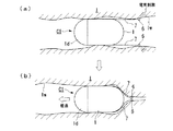
図1(a)、(b)及び図2に示すカプセル型医療装置C1は、本実施形態に係るカプセル型医療装置の基本形態となるものである。このカプセル型医療装置C1は、撮像部(生体情報取得手段)2と、制御部(電流制御手段)3と、無線送受信部(通信手段)4と、各構成部に電力を供給する電池5とを筐体1内に一体に備えているとともに、一対の電極6、6と、これら一対の電極6,6間の距離を可変とする電極間距離可変手段としての可撓性の可撓性電線7,7と、を備えた構成とされた、無線式のカプセル型医療装置である。
[First Embodiment]
First, a first embodiment will be described with reference to FIGS.
The capsule medical device C1 shown in FIGS. 1A, 1B, and 2 is a basic form of the capsule medical device according to the present embodiment. The capsule medical device C1 includes an imaging unit (biological information acquisition unit) 2, a control unit (current control unit) 3, a wireless transmission / reception unit (communication unit) 4, and a
筐体1は、軸線L方向を長手方向として延びるカプセル形状をなしており、プラスチック等で内部を密閉するように形成されている。筐体1の前端側には、半球形状をなす透明ドーム1dが設けられている。この透明ドーム1dの内側、つまり筐体1の前方側(軸線L方向前方側)には、体内の各部を撮像することにより撮像画像を得るための、レンズ及びCCD(charge coupled device)等からなる撮像素子2aと、及び照明光を照射して撮像素子2aの視野範囲を照明するための、EL(electroluminescence)素子やLED(発光ダイオード)等からなる発光素子2bとが配されている。これら撮像素子2a及び発光素子2bによって、生体内を撮像することで生体情報を取得する撮像部2が構成されている。
The
無線送受信部4は、図示しない送受信部本体と電波を発信及び受信する送受信アンテナ(発信アンテナ、受信アンテナ)とから構成されており、生体情報、すなわち撮像素子2aで撮像した撮像画像を、後述する体外装置100に無線送信できるようなっている。また、無線送受信部4は、体外装置100から無線送信された後述する制御信号(指令)を受信して制御部3に送るようになっている。
The wireless transmission /
制御部3は、無線送受信部4からの制御信号(指令)に基づいて、カプセル型医療装置C1内における各構成部の動作を総合的に制御する機能を有しているものである。またこの制御部3内には、可撓性電線7,7を介して電極6,6に電流を流すための電流発生回路3aが設けられている。すなわち制御部3は、電極6,6に流す電流を制御する電流制御手段としての機能も有している。
The
可撓性電線7,7は、金属等の可撓性を有する導電性材料を有する構成されており、その基端側を筐体1の後方側(軸線L方向の一方の端部側)に各々支持されている。そして筐体1から互いに径方向に離間するようにして外方へ向かって突出し、先端側で電極6,6を各々支持している。つまり電極6,6は、可撓性電線7,7を介して筐体1の後方側に設けられている。可撓性電線7,7は、筐体1内で制御部3と連結されており、電流発生回路3aからの電流を電極6,6へと各々流すとともに、弾性変形することで電極6,6間の距離を可変とする機能を有している。そのため、生体内における管腔の径の差異を的確に吸収することができる。
なお、これら可撓性電線7,7は、超弾性合金により構成されていることが好ましい。このように、超弾性合金を用いることとすれば、通常の金属等と比較して弾性変形可能範囲がより広範となるため、生体内における管腔の径の差異を更に的確に吸収することができる。
The flexible
In addition, it is preferable that these flexible
電極6,6は、生体組織と接触し、生体組織に対して電気刺激を与えるためのものであり、カプセル型医療装置C1の推進を阻害しないように略球形状をなしている。これら電極6,6は、ステンレス、プラチナ、チタンのうちの少なくとも一の材料から構成されている。そのため、電気伝導度が高く高効率で電流を流すことができるとともに、電極に高い生体適合性を持たせることができる。
The
なお、図1(a)、(b)に示すように、電極6,6が径方向に離間する最大距離、つまり可撓性電線7,7によって変化される電極間距離の最大値(X)としては、カプセル型医療装置C1の外径(D)の略2倍以上(X≧2D)が好適である。カプセル型医療装置C1は、体内(生体内)への導入時における導入のし易さを考慮すると、外径を徒に大きくすることは好ましくなく、例えば10mm前後(好ましくは11mm程度)が適切である。しかしながら、管腔臓器の中では内径が小さい部類に入る小腸でさえ、内径が20〜30mmはあるとされている。そのため、電極6,6によって管腔内の生体組織に対して的確に電気刺激を与えるためには、電極6,6間の最大離間距離は、カプセル型医療装置C1の外径の約2倍以上(好ましくは約3倍以上)であることが適切である。
As shown in FIGS. 1A and 1B, the maximum distance that the
また、可撓性電線7,7は、基端側から先端側の電極6,6へと電流を流す導電性線材を、樹脂等の絶縁性部材によって絶縁被覆した構成とされていてもよいし、導電性線材が剥き出しとなっていて電極6,6と一体となって生体組織に電気刺激を与えられるような構成とされていてもよい。導電性線材が剥き出しとなっている場合には、生体組織に電気刺激を与える際に、より大きな電気的接触面積を確保して通電できるため、電気刺激に必要な電流量を安定して送ることができる。
なお、図1(c)に示すように、可撓性電線7,7を帯状電線(符号7w,7w)とし、電極6,6もそれに合わせてほぼ同幅の横長電極(符号6w,6w)としてもよい。こうすることにより、更に大きな電気的接触面積を確保することができ、より安定して、収縮に必要な電流量を生体組織に送ることが可能となる。
In addition, the flexible
In addition, as shown in FIG.1 (c), let the flexible
更に、導電性線材自体は超弾性合金のような高弾性体ではなく、導電性線材を絶縁被覆する絶縁性部材が、超弾性特性を有する樹脂(超弾性高分子材料)等により構成されており、結果として可撓性電線7,7が超弾性特性を有するような構成とされていてもよい。
更に、電極6,6と可撓性電線7,7は、カプセル型医療装置C1の径方向に180°間隔で一対配設しているが、例えば90°間隔で二対(合計4つ)配設するようにしてもよい。このようにすると、電極6,6をより確実に生体組織に接触させることができる。
Furthermore, the conductive wire itself is not a highly elastic body such as a superelastic alloy, and the insulating member that insulates and coats the conductive wire is made of a resin (superelastic polymer material) having superelastic characteristics. As a result, the flexible
Furthermore, the
体外装置100は、カプセル型医療装置C1を体外から制御するものであり、図2に示すように、装置本体100内に、カプセル型医療装置C1との間で情報を送受信する無線送受信部(発信部、検知部)102と、上記生体情報、即ち、撮像画像を蓄積するメモリ等の記録部103と、これら各構成部を制御する制御部104と、各構成部に電力を供給する電池105とを、装置本体101内に備えた構成とされている。
The
装置本体101は、アルミ等の金属やプラスチック等で箱状に形成され、被検者のベルト等を介して身体に装着可能とされており、これにより常に被検者の体外に配されるようになっている。
無線送受信部102は、カプセル型医療装置C1の無線送受信部4と同様に、図示しない送受信部本体と電波を発信及び受信する送受信アンテナ(発信アンテナ、受信アンテナ)とから構成されており、カプセル型医療装置C1から無線送信されてきた生体情報である撮像画像を受信するとともに、制御部104に送る機能を有している。
The apparatus
Similar to the wireless transmission /
制御部104は、送られてきた撮像画像を画像処理等の所定処理を行った後に、記録部103に随時記録するようになっている。更に、制御部104には、体内におけるカプセル型医療装置C1の位置を検出する位置検出回路104aが組み込まれている。位置検出回路4は、例えば、予め設定画像(基準画像)が設定されており、この設定画像と送られてきた撮像画像とを比較することにより、体内におけるカプセル型医療装置C1の位置を検出するようになっている。なお、位置検出回路104aは、撮像画像と設定画像とを比較することでカプセル型医療装置C1の位置を検出したが、これに限られるものではなく、撮像画像内の所定の色や形状等の特徴量に基づいてカプセル型医療装置C1の位置を検出するようにしても構わない。
The
更に、位置検出回路104aは、撮像画像により位置を検出するものではなく、無線送受信部4から体外に送信される、あるいは体外から受信した電波の強度によって、位置を検出するものであってもよい。この場合、体外装置100側の無線送受信部102に複数のアンテナを設け、これら複数のアンテナの位置と電波の強度によって、三角測量などにより位置の算出を行うことができる。また、カプセル型医療装置C1あるいは体外装置100の何れかに、磁界発生コイルと磁気センサ(あるいは磁気誘導コイル)の何れかを搭載し、体内あるいは体外で発生した磁界をその逆(体外あるいは体内)で検出し、位置を算出するような構成としてもよい。
Furthermore, the
更に、制御部104は、位置検出回路104aにより検出されたカプセル型医療装置C1が位置している生体組織の部位(例えば、胃、小腸や大腸)に応じた制御信号を、無線送受信部102を介してカプセル型医療装置C1に送る機能を有している。
Further, the
このように構成されたカプセル型医療装置C1により、被検者の体内を観察する場合について説明する。
まず、ベルト等を介して体外装置100を装着した後、被検者は、カプセル型医療装置C1を経口投入(飲み込み)することにより、体内(生体内)に導入する。なおこの体内導入前には、図3に示すように、デンプン等の生体吸収材料からなる電線結束バンド(電線結束手段)7Bによって可撓性電線7,7同士を予め結束しておき、飲み込み時において可撓性電線7,7及び電極6.6が邪魔にならないようにしておく。
この経口投入時においてカプセル型医療装置C1には、図示しないスイッチが入るようになっており、電池5から各構成品に電力が供給される。これにより、制御部3は、撮像部2、即ち、撮像素子2a及び発光素子2bを作動させる。
A case where the inside of the subject's body is observed with the capsule medical device C1 configured as described above will be described.
First, after attaching the
At the time of oral injection, a switch (not shown) is turned on in the capsule medical device C1, and power is supplied from the
体内に投入されたカプセル型医療装置C1は、消化管を移動しながら撮像素子2aにより体内各部を撮像するとともに、撮像画像を無線送受信部4により体外装置100に向けて無線送信する。一方、体外装置100は、無線送受信部102を介して撮像画像を受信するとともに、制御部104により撮像画像の画像処理等を行って、記録部103に随時記録していく。そして制御部104は、位置検出回路104aにより検出されたカプセル型医療装置C1が位置している生体組織内の部位(例えば、胃、小腸や大腸)に応じた制御信号を、無線送受信部102を介してカプセル型医療装置C1へと随時送信する。
The capsule medical device C1 placed in the body images each part of the body by the
カプセル型医療装置C1が胃に達した場合、電線結束バンド7Bは胃酸によって溶解されて体内に吸収されて、電極6,6及び可撓性電線7,7は結束を解かれて展開可能となり、電極6,6間の距離は可変となる。ここからは、操作者が撮像画像を見ながら、胃、十二指腸、小腸や大腸等といった生体組織に対して適宜電気刺激を与えて、カプセル型医療装置C1を推進させていく。例えば撮像画像の変化が激しい場合であれば、カプセル型医療装置C1は高速移動中ということであるので、電極6,6に電流を流す頻度を少なくして、移動速度を遅くするようにする。また逆に、撮像画像がさほど変化しない場合であれば、カプセル型医療装置C1は停滞中ということであるため、電極6,6に電流を流す頻度を多くして、移動速度を上げるようにする。
When the capsule medical device C1 reaches the stomach, the
次に、カプセル型医療装置C1が胃及び十二指腸を通過して小腸Iに達した場合について、図4に示す。このとき、体外装置100から電気刺激を与える旨の制御信号を受信した場合には、制御部3は電極6,6に電流を流し、小腸Iの腸壁Iwに電気刺激を与える(図4(a))。電気刺激を受けた部分の近傍の小腸Iは収縮し、カプセル型医療装置C1は、この収縮した小腸Iに押し出されるようにして進行方向に向けて推進する(図4(b))。なおこのとき、小腸Iの収縮に伴って可撓性電線7,7は弾性変形するので、小腸Iの径の変化を的確に吸収することができる。このため、小腸Iの自律的な蠕動運動によって移動するよりも確実に小腸I内を移動でき、時間を短縮して効率的な小腸内の観察を行うことができる。
Next, FIG. 4 shows a case where the capsule medical device C1 reaches the small intestine I through the stomach and duodenum. At this time, when receiving a control signal for applying electrical stimulation from the
このようにして、次の大腸も同様に通過していき、肛門から体外へと排泄される。そして医師等は、体外装置100の記録部103に記録された生体情報である撮像画像に基づいて、被検者の健康状態の診断を行う。
In this way, the next large intestine also passes through and is excreted from the anus to the outside of the body. The doctor or the like diagnoses the health condition of the subject based on the captured image that is the biological information recorded in the
なお、上記したように、撮像画像の変化からカプセル型医療装置C1の移動速度を推測するのではなく、カプセル型医療装置C1に移動速度を検出するための速度センサあるいは加速度センサ等の移動速度検出手段を設け、当該センサの検出結果に基づいて、カプセル型医療装置C1内だけで電気刺激用の電流量やタイミングを調整するようにしてもよい。すなわち、体外装置100に依存せずに、カプセル型医療装置C1を自動的に一定速度で移動させ、生体情報を取得することができる。体外装置100は、カプセル型医療装置C1が取得した生体情報を受信し、記録等するだけでよいので、処理が簡便で済む。
As described above, instead of estimating the moving speed of the capsule medical device C1 from the change in the captured image, the moving speed detection such as a speed sensor or an acceleration sensor for detecting the moving speed in the capsule medical device C1 is performed. Means may be provided, and the current amount and timing for electrical stimulation may be adjusted only within the capsule medical device C1 based on the detection result of the sensor. That is, without depending on the
更に、撮像画像による処理を行わないため、カプセル型医療装置C1に撮像センサを搭載せず、撮像機能以外の機能を有する生体情報取得センサ(体内のpHを取得するためのpHセンサ、管腔臓器の管腔内壁の断層像を取得するための超音波センサあるいは光断層センサ、ガン等の特定の生体組織を画像化するためのマイクロ波画像化センサ、温度を検出するための温度センサ、体内からの出血を検知するための出血センサ、特定の患部が産出する酵素等の化学物質を検出するための化学センサ、腸内細菌の存在・量を検出するための化学センサ、等)を搭載する場合にも適した自動推進方式である。 Furthermore, since the processing based on the captured image is not performed, the capsule-type medical device C1 is not equipped with an imaging sensor, and has a function other than the imaging function (biological information acquisition sensor (pH sensor for acquiring body pH, luminal organ) An ultrasonic sensor or optical tomographic sensor for acquiring a tomographic image of the inner wall of a lumen, a microwave imaging sensor for imaging a specific biological tissue such as a cancer, a temperature sensor for detecting temperature, from the body Equipped with bleeding sensors for detecting bleeding, chemical sensors for detecting chemical substances such as enzymes produced by specific affected areas, chemical sensors for detecting the presence and amount of intestinal bacteria, etc.) This is an automatic propulsion method suitable for the same.
このカプセル型医療装置C1においては、カプセル形状をなす筐体1と、筐体1内に設けられた、前記生体情報を取得する撮像部2と、撮像部2が取得した生体情報を無線により体外に送信する無線送受信部4と、前記筐体の軸線方向の一方の端部側に設けられ、前記生体内の生体組織に対して電気刺激を与えるための少なくとも一対の電極6,6と、これら電極に流す電流を制御する制御部3と、電極6,6同士の間の距離を可変とする電極間距離可変手段としての可撓性電線7,7と、を備えるようにしている。
このような電極間距離可変手段を設けているので、生体組織に電極6,6を的確に接触させて電気刺激を与え、生体組織の収縮動作を的確に行わせることが可能となり、カプセル型医療装置C1の安定した推進を実現することができる。
In the capsule medical device C1, a capsule-shaped
Since the inter-electrode distance varying means is provided, it becomes possible to accurately contact the living tissue with the
また、電極6,6を、ステンレス、プラチナあるいはチタンといった材料から構成するようにしているので、電気伝導度が高く高効率で電流を流すことができるとともに、電極6,6に高い生体適合性を持たせることができる。
Further, since the
更に、基端側を筐体1に支持されて筐体1から外方へ向かって突出し、先端側で電極6,6を支持する可撓性の可撓性可撓性電線7,7によって、電極間距離可変手段を構成するようにしている。このため、簡易な構成として容易に弾性変形させることができるので、電極6,6を生体組織により的確に接触させることができるとともに、管腔内に導入された際にこの管腔の径の差異を的確に吸収することができる。
Furthermore, the base end side is supported by the
更に、可撓性電線7,7を超弾性合金により構成するようにすれば、弾性変形可能範囲がより広範となるため、生体内における管腔の径の差異を更に的確に吸収することができる。
Furthermore, if the flexible
更に、可撓性電線7,7の先端側同士を結束する、生体吸収材料からなる電線結束バンド7Bを設けるようにしているので、カプセル型医療装置C1の経口投入(飲み込み)時において、電極6,6及び可撓性電線7,7が邪魔になることがなく、より容易に体内に導入することができる。そして導入後においては、電線結束バンド7Bは、胃酸により溶解される等して生体に吸収されるので、生体内で可撓性電線7,7同士の結束は解かれ、電極6,6間の距離を可変とすることができる。
Furthermore, since the electric
上記のカプセル型医療装置C1の各変形例について、以下に示す。
なお、カプセル型医療装置C1における、撮像部2(撮像素子2a及び発光素子2b)、制御部3、無線送受信部4及び電池5といった各構成要素は、以下の各変形例に係るカプセル型医療装置の全てにおいて同様に設けられている、共通の構成要素である。そのため、以下において、これら構成要素の図示や詳細な説明は省略することとする。またこの他にも、カプセル型医療装置C1における構成要素と同様の構成要素については、同一の符号を付して、その詳細な説明は省略することとする。
Each modification of the capsule medical device C1 will be described below.
In the capsule medical device C1, the constituent elements such as the imaging unit 2 (
先ず図5に、第1の変形例を示す。
このカプセル型医療装置C2は、上記カプセル型医療装置C1における筐体1の前方側(軸線L方向の他方の端部側)に、一対の前側電極(第2の電極)8,8と、これら一対の前側電極8,8間の距離を可変とする第2の電極間距離可変手段としての可撓性の前側可撓性電線9,9と、を付加した構成とされている。これら前側電極8,8及び前側可撓性電線9,9は、電極6,6及び可撓性電線7,7と略同一の構成とされている。
First, FIG. 5 shows a first modification.
The capsule medical device C2 includes a pair of front electrodes (second electrodes) 8 and 8 on the front side (the other end side in the axis L direction) of the
前側可撓性電線9,9は、その基端側を、筐体1の前方側(軸線L方向の他方の端部側)であって透明ドーム1dよりも後方側に、各々支持されている。そして筐体1から互いに径方向に離間するようにして外方へ向かって突出し、先端側で前側電極8,8を各々支持している。つまり電極8,8は、可撓性電線7,7を介して、筐体1の前方側であって撮像部2以外の部分に設けられており、撮像部2による撮像を阻害しないようになっている。
また前側可撓性電線9,9は、筐体1内で制御部3(図2に図示)と連結されており、電流発生回路3aからの電流を前側電極8,8へと各々流すとともに、弾性変形することで前側電極8,8間の距離を可変とする機能を有している。なお、ここでの制御部3は、無線送受信部4からの制御信号(指令)に基づいて、電極6,6に流す電流の制御とは独立して前側電極8,8に流す電流を制御する、第2の電流制御手段としての機能も有している。
The front flexible wires 9 and 9 are respectively supported at the base end side on the front side of the casing 1 (the other end side in the direction of the axis L) and on the rear side of the
Further, the front flexible wires 9 and 9 are connected to the control unit 3 (shown in FIG. 2) in the
このカプセル型医療装置C2においては、筐体10の後方側に設けた電極6,6及び可撓性電線7,7以外に、前方側にも前側電極8,8及び前側可撓性電線9,9を設けるようにし、これらに流す電流を互いに独立して制御可能なようにしているので、カプセル型医療装置C2を、生体組織内において任意に前後進させることができる。すなわち、前進させたいときは、筐体10の後方側に設けた電極6,6によって生体組織に電気刺激を与え、また逆に後進させたいときは、筐体10の前方側に設けた前側電極8.8によって生体組織に電気刺激を与えるようにする。これにより、カプセル型医療装置C2が、例えば小腸や大腸等の管腔内に位置している場合に、操作者は撮像画像を見ながら適宜前後進させることができ、操作性を向上させることができる。また、狭い管腔内に前後どちらから進入しても、容易に対応することができる。更に、前後進が可能なことにより、管腔内をくまなく隅々まで観察することが可能となる。
In the capsule medical device C2, in addition to the
なおここでは、制御部3が、制御手段としての機能と第2の制御手段としての機能とを兼ね備えるような構成としているが、これら2つの機能を各々別個に担保させるように、2つの制御部を設けるような構成としてもよい。
また、撮像部を後側にも設けるようにしてもよい。こうすれば、より隅々までくまなく観察することが可能となる。
Here, the
Moreover, you may make it provide an imaging part also in the back side. In this way, it becomes possible to observe all over the corner.
次に、図6及び図7に、第2の変形例を示す。
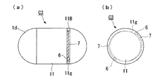
このカプセル型医療装置C3は、上記カプセル型医療装置C1とは筐体の構成が異なっている。すなわちこのカプセル型医療装置C3の筐体11には、その外周にわたって、電極6及び可撓性電線7を収納する溝11gが形成されている。このカプセル型医療装置C3の体内導入前には、図6に示すように、デンプン等の生体吸収材料からなる電線バインダ(電線固定手段)11Bによって電極6,6及び可撓性電線7,7を溝11g内に予め固定しておき、飲み込み時において可撓性電線7,7及び電極6.6が邪魔にならないようにしておく。
そして、カプセル型医療装置C1が胃に達した場合、電線結束バンド7Bは胃酸によって溶解されて体内に吸収され、図7に示すように、電極6,6及び可撓性電線7,7は固定を解かれて展開可能となり、電極6,6間の距離は可変となる。
Next, FIGS. 6 and 7 show a second modification.
The capsule medical device C3 is different from the capsule medical device C1 in the configuration of the casing. That is, the
When the capsule medical device C1 reaches the stomach, the
このカプセル型医療装置C3においては、電極6,6及び可撓性電線7,7を収納する溝11gを筐体11の外周にわたって形成しているので、可撓性電線7,7を収納するスペースを少なくして、電極6,6の不使用時には、可撓性電線7,7を筐体11の外周面から突出しないように収納することができる。
In this capsule medical device C3, the
また、生体吸収材料からなる電線バインダ11Bによって電極6,6及び可撓性電線7,7を溝11g内に固定しているので、カプセル型医療装置C3の飲み込み時において、電極6,6及び可撓性電線7,7が邪魔になることがなく、より容易に体内に導入することができる。そして導入後においては、電線バインダ11Bは胃酸により溶解されて体内に吸収されるので、体内で電極6,6及び可撓性電線7,7の固定は解かれ、電極6,6間の距離を可変とすることができる。そのため、カプセル型医療装置C3の飲み込み時には、筐体11からの突起物を無くして飲み込み易くできるとともに、体内では電極6,6及び可撓性電線7,7を的確に展開させることができる。
In addition, since the
次に図8及び図9に、第3の変形例を示す。
このカプセル型医療装置C4は、上記カプセル型医療装置C1とは、筐体の構成及び可撓性電線の構成が異なっている。
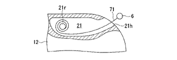
このカプセル型医療装置C4においては、筐体12に、可撓性電線71,71及び電極6,6を筐体12内部に収納する電線収納部21,21が各々設けられている。そして、可撓性電線71,71は、形状記憶合金により構成されている。
Next, FIGS. 8 and 9 show a third modification.
The capsule medical device C4 is different from the capsule medical device C1 in the configuration of the casing and the configuration of the flexible electric wire.
In this capsule medical device C4, the
電線収納部21,21は、開口部21h,21hから電極6,6及び可撓性電線71,71を外部へと出没可能として、筐体12の後方側に空洞状をなして形成されている。電線収納部21,21内には、回転軸21r,21rが各々回転自在に支持されており、これら回転軸21r,21rには、可撓性電線71,71の基端側が各々連結されている。すなわち制御部3からの電流は、回転軸21r,21r及び可撓性電線71,71を介して、電極6,6に流されるようになっている。
The electric
可撓性電線71,71は、形状記憶合金により構成されている。これら可撓性電線71,71は、30℃以下の温度では略ゼンマイ状に巻かれた状態となり、35℃以上の温度では略直線状に形状復帰するように、形状記憶がなされている。可撓性電線71,71にこのような形状記憶をさせていることで、体内への導入前、すなわち室温(25℃前後)付近の温度域においては、可撓性電線71,71を電線収納部21,21内に略ゼンマイ状に巻いた状態で収納しておくことができる。そして、体内への導入後においては、体温(36℃前後)付近の温度域となるので、可撓性電線71,71を略直線状に形状復帰させて、開口部21h,21hから筐体12の外方へと、自動的に繰り出すことができる。そのため、カプセル型医療装置C4の飲み込み時には、電極6,6及び可撓性電線71,71を電極収納部21,21内に収納しておき、筐体12からの突起物を無くして飲み込み易くできる。そして、体内にて体温付近まで温度が上昇すると、電極6,6及び可撓性電線71,71を的確に展開させて、生体組織に対して電気刺激を与えることができる。
The flexible
なお、40℃以上の温度で、略ゼンマイ状に巻かれた状態から略直線状に形状復帰するように、可撓性電線71,71に形状記憶をさせるとともに、制御部3によって制御されて電線収納部21,21内を加温する加温手段(図示省略)を備えるようにしてもよい。可撓性電線にこのような形状記憶をさせていれば、体内への導入前には、可撓性電線71,71を回転軸21r,21rに略ゼンマイ状に巻いた状態で、電線収納部21,21内に収納しておくことができる。そして、体内への導入後においては、体温(36℃前後)付近の温度域となっても可撓性電線は形状復帰されないため、加温手段によって40℃以上に加温した場合にのみ形状復帰させることができる。すなわち、生体内では加温手段を動作させなければ可撓性電線71,71を略直線状に形状復帰させることはできないようにしているので、体外からの制御信号によって任意の位置で加温手段を動作させることで、当該位置で可撓性電線を的確に繰り出すことができる。そのため、電極6,6及び可撓性電線71,71を的確に展開させて、生体組織に対して電気刺激を与えることができる。
The flexible
次に図10乃至図12に、第4の変形例を示す。
このカプセル型医療装置C5は、上記カプセル型医療装置C1とは電極間距離可変手段の構成が異なっている。すなわち、電極61,61が一体に固定されて、筐体13の外側に、この筐体13に対して互いに径方向に離間するように移動可能に取り付けられた外殻部72a,72bが、電極間距離可変手段とされている。
Next, FIGS. 10 to 12 show a fourth modification.
This capsule medical device C5 is different from the capsule medical device C1 in the configuration of the interelectrode distance varying means. That is, the
外殻部72a,72bは、筐体13の長手方向略中央部分から後端のテーパー部分までの外側を覆うような半割状の殻部をなして、筐体13に取り付けられている。つまり、これら外殻部72a,72bを閉じた状態においては、図10に示すように、筐体13の長手方向略中央部分から後方は、外殻部72a,72bによって覆われている。これら外殻部72a,72bと筐体13との間には、バネ72s,72sが各々介装されており、外殻部72a,72bを径方向外側に各々付勢するようになっている。また、これら外殻部72a,72bの外側には、電極61,61が各々固定・実装されている。これら複数の電極61は制御部3と電気的に接続されており、制御部3からの電流が流されるようになっている。
The
また、このカプセル型医療装置C5には、制御部3によって制御されて外殻部72a,72bの係止及び解除を行う、係止手段(図示省略)が備えられている。すなわち、体内への導入前においては、図10に示すように、外殻部72a,72bを閉じた状態で係止しておく。そして、体内への導入後においては、体外からの制御信号によって任意の位置で係止を解除する。こうすると図11に示すように、バネ61s,61sの付勢力によって、外殻部72a,72bは径方向外側に各々移動されて展開し、電極61,61管の距離は可変となる。
In addition, the capsule medical device C5 is provided with locking means (not shown) that is controlled by the
このカプセル型医療装置C5においては、電極61,61が一体に固定され、筐体13の外側に筐体13に対して径方向に移動可能に取り付けられた外殻部72a,72bによって、電極間距離可変手段を構成するようにしている。そのため、外殻部72a,72bに複数の電極61,61を実装して、それらを一体的に径方向に移動させることができ、電極61,61を生体組織により的確に接触させることができる。また、例えば管腔からの押圧力がバネ72s,72sの付勢力を上回る場合には、外殻部72a,72bは適宜閉じるように移動可能であるので、カプセル型医療装置C5の安定した推進を確保することができる。
In this capsule medical device C5, the
ここで、電極61の変形例について、図12に示す。
図12(a)に示す電極61aは、外殻部72aの外面から半球状をなして突出する半球型電極とされている。このような半球型電極とすれば、生体組織と接触し易くすることができるとともに、角隅部が無いためにカプセル型医療装置C5をより滑らかに推進させることができる。
Here, a modification of the
The
また、図12(b)に示す電極61bは、外殻部72aの外面から円柱状をなして突出する円柱型電極とされている。このような円柱型電極とすれば、生体組織との接触面積を広くとることができるので、例えば粘膜のような生体組織に対しても、的確に電気刺激を与えることができる。
Further, the
更に、図12(c)に示す電極61cは、外殻部72aの外面と略面一となって連なるように外殻部72aに埋め込んだ埋込型電極とされている。このような埋込型電極とすれば、外殻部72aの外面から電極を突出させず、滑らかに連続させることができるので、カプセル型医療装置C5を更に滑らかに推進させることができる。
Further, an
あるいは、図示は省略するが、外殻部72a,72bの略全体を電極としてもよい。このようにした場合、電極による突起等が無くなるため、安定した電気的接触面積を確保しながら、より滑らかな推進を実現することが可能となる。
Or although illustration is abbreviate | omitted, it is good also considering the substantially whole of
なお、外殻部72a,72bが展開した後に、外殻部72a,72bを筐体13に係止・固定させるような構成としてもよい。
Note that the
また、外殻部72a,72bと筐体13との間には、バネ72s,72sに替えて、吸水時に膨張する吸水ゲルを介装させるようにしてもよい。このように吸水ゲルを用いることとすれば、体内への導入後において吸水した際に外殻部72a,72bを径方向外側に移動させて展開することができるので、簡易な構成として的確に電極61,61間の距離を可変とすることができる。
あるいは、バネ72s,72sを形状記憶合金で構成し、体内の温度によってバネ72s,72sを伸張させて、外殻部72a,72bを展開させるようにしてもよい。
Further, a water-absorbing gel that expands during water absorption may be interposed between the
Alternatively, the springs 72s and 72s may be made of a shape memory alloy, and the
次に図13乃至図15に、第5の変形例を示す。
このカプセル型医療装置C6は、カプセル型医療装置C1において一対しか設けられていなかった電極及び可撓性電線を、筐体の周上により多数設けるとともに、電流を流す電極を選択可能な手段(電極セレクタ)を備えた構成とされている。
Next, FIGS. 13 to 15 show a fifth modification.
This capsule medical device C6 is provided with a number of electrodes (flexible electric wires) that are provided only in a pair in the capsule medical device C1 and a flexible electric wire on the periphery of the casing, and means that can select an electrode for passing a current (electrode) Selector).
カプセル型医療装置C6の筐体14の後方側には、この筐体14の周上に略等間隔で多数の電極6,6,…及び可撓性電線7,7,…が設けられているとともに、可撓性電線7,7,…の基端側は、筐体14内に設けられた電極セレクタ6sに連結されている。この電極セレクタ6sは、多数の電極6,6,…のうちから、電流を流す一対の電極を選択するものであって、制御部3によって制御される。すなわち制御部3からの電流は、電極セレクタ6s及び可撓性電線7,7を介して、選択された一対の電極6,6に流されるようになっている。
On the rear side of the
ここで、電極6の変形例について、図14に示す。
図14(a)には、略球形状の電極6を示しているが、これに限定されるものではなく、図14(b)に示すフック形状の電極6a、図14(c)に示す輪形状の電極6b、図14(d)に示す棒状の電極6c、図14(e)に示す、より大きな接触面積が得られる電極6d等、カプセル型医療装置C6の使用態様に応じて、電極形状は適宜変更が可能である。
Here, a modification of the
FIG. 14A shows a substantially
こうした構成のカプセル型医療装置C6が大腸Rに達した状態を、図15に示す。大腸Rのような比較的広い管腔内においては、前後進だけでなく横方向にも移動したい場合や、視野変換をしたい場合等がある。このとき、進みたい方向と反対側にある電極6,6…であって且つ管腔壁(腸壁Rw)に接触している電極6を選択して電流を流すと、前後進と横移動とを組み合わせたような推進を実現することができる。なお、腸壁Rwに接触している電極6を選択するには、各々の電極6,6…に微弱電流を流してみて、そのインピーダンスを計測することで、把握することができる。
FIG. 15 shows a state where the capsule medical device C6 having such a configuration reaches the large intestine R. In a relatively wide lumen such as the large intestine R, there are cases where it is desired not only to move forward and backward but also to move laterally, or to change the visual field. At this time, when the
このカプセル型医療装置C6においては、筐体14の周上に多数の電極6,6…及び可撓性電線7,7…を設けて、電流を流す電極を選択可能としているので、電気刺激を与える部位を周方向に選択することができる。これにより、カプセル型医療装置C6を横方向にも的確に移動させることができるので、管腔内をくまなく隅々まで観察することが可能となる。
In this capsule medical device C6, a large number of
次に図16に、第6の変形例を示す。
このカプセル型医療装置C7は、上記カプセル型医療装置C5における電極の配置を変更したものであって、外殻部72a,72bの外面の略全面にわたって電極を設けるとともに、こうした電極を多数の電極61d,61d,…に分割して、通電する電極61d,61d,…を任意に選択可能な構成とされている。
Next, FIG. 16 shows a sixth modification.
This capsule medical device C7 is obtained by changing the arrangement of the electrodes in the capsule medical device C5. The capsule medical device C7 is provided with electrodes over substantially the entire outer surfaces of the
電極61d,61d,…は、外殻部72a,72bの外面に各々密集配置された面状電極であって、筐体13内に設けられた電極セレクタ6s2に各々連結されている。この電極セレクタ6s2は、上記カプセル型医療装置C6における電極セレクタ6sと同様、電流を流す電極61d,61d,…を選択可能な手段であるが、一対をなす極の各極毎に複数の電極61d,61d,…を任意に選択し、同時に通電可能となっている。すなわちこの電極セレクタ6s2は、生体組織に対して電気刺激を与えるための電極面積を各極毎に変化させる、電極面積可変手段としての機能を有している。
The
このカプセル型医療装置C7においては、生体組織に対して電気刺激を与えるための電極の面積を各極毎に可変としているので、最適な位置の電極を選択できるとともに、最適な電極面積を各極毎に確保することができ、所望の電流量を生体組織に対して流し易くすることができる。そのため、例えば腸の効率的な収縮に必要な電流量を流すための電極面積を確保できるとともに、腸内壁といった生体組織との接触状態が良い電極を選択することができる。 In this capsule medical device C7, since the area of the electrode for applying electrical stimulation to the living tissue is variable for each pole, the electrode at the optimum position can be selected and the optimum electrode area can be selected for each pole. It can be ensured every time, and a desired amount of current can be easily flowed to the living tissue. Therefore, for example, an electrode area for flowing an amount of current necessary for efficient intestinal contraction can be secured, and an electrode having a good contact state with a living tissue such as an intestinal inner wall can be selected.
[第2の実施の形態]
次に、第2の実施形態について、図17乃至図25を用いて説明する。
なお、本実施形態においては、上記第1の実施形態における構成要素と同様の構成要素については、同一の符号を付して、その詳細な説明は省略することとする。
[Second Embodiment]
Next, a second embodiment will be described with reference to FIGS.
In the present embodiment, the same components as those in the first embodiment are denoted by the same reference numerals, and detailed description thereof is omitted.
図17乃至図20に示すカプセル型医療装置C10は、本実施形態に係るカプセル型医療装置の基本形態となるものである。このカプセル型医療装置C10は、上記第1の実施形態において示したカプセル型医療装置C4において、可撓性電線及び電極の繰り出し・巻き取りを任意に行い得るようにしたものである。具体的には、カプセル型医療装置C4にモータ(アクチュエータ)Mを設けるとともに、回転自在であった回転軸21rに替えて、モータMによって回転駆動される回転軸22rを設けた概略構成とされている。
A capsule medical device C10 shown in FIGS. 17 to 20 is a basic form of the capsule medical device according to the present embodiment. The capsule medical device C10 is configured so that the flexible electric wire and the electrode can be arbitrarily taken out and wound up in the capsule medical device C4 shown in the first embodiment. Specifically, the capsule medical device C4 is provided with a motor (actuator) M, and instead of the rotatable
モータM,Mは、筐体12内における電線収納部21,21の近傍位置に各々設けられており、制御部3によってその動作を制御されるようになっている。これらモータM,Mからの回転駆動力は、ギヤ等の動力伝達手段を介して回転軸22rに伝達される。すなわち、これらモータM,Mと回転軸22r,22rとで、可撓性電線7,7の繰り出し・巻き取り機構が構成されている。こうした構成の繰り出し・巻き取り機構においては、体外からの制御信号によってモータM,Mの動作を制御して、任意の位置で可撓性電線7,7を繰り出して電極6,6を展開する、あるいは巻き取りして可撓性電線7,7及び電極6,6を電線収納部21,21内に完全収納することができる。これらモータM,Mとしては、電磁モータ、超音波モータ、静電モータ等の、モータ/アクチュエータの何れかが用いられる。
The motors M, M are provided in the vicinity of the electric
なおこのカプセル型医療装置C10においては、上記カプセル型医療装置C4のように、可撓性電線の自動的な形状変化を利用して繰り出し・巻き取りを行うものではないので、可撓性電線に形状記憶合金等は用いず、上記カプセル型医療装置C1等におけると同様、超弾性合金等からなる可撓性電線7,7を用いることとしている。
In this capsule type medical device C10, unlike the capsule type medical device C4, the automatic shape change of the flexible wire is not used for feeding and winding. As in the capsule medical device C1 or the like, the flexible
可撓性電線7,7をほぼ最大限まで巻き取り、電極6,6及び可撓性電線7,7を電極収納部内に完全収納した状態を、図17に示す。後述するように、カプセル型医療装置C10の飲み込み時や、肛門からの排泄時等においては、この状態とする。
一方、可撓性電線7,7を最大限まで繰り出し、電極6,6及び可撓性電線7,7を最大展開した状態を、図20に示す。後述するように、カプセル型医療装置C10が胃に到達した時等においては、この状態とする。
なお、モータM,Mの動作を制御することによって、可撓性電線7,7の繰り出し量及び巻き取り量を任意に変化させることができるので、例えば図19に示すように、可撓性電線7,7を完全収納状態から少しだけ繰り出して、ほぼ電極6,6のみが開口部21h,21hから突出するような状態とすることもできる。
FIG. 17 shows a state where the flexible
On the other hand, FIG. 20 shows a state in which the flexible
Note that, by controlling the operation of the motors M and M, the amount of feeding and winding of the
このように構成されたカプセル型医療装置C10により、被検者の体内を観察する場合について、図21及び図22を用いて説明する。
まず、ベルト等を介して体外装置100を装着した後、被検者は、カプセル型医療装置C10を経口投入(飲み込み)する。なおこの体内導入前には、図17に示すように、可撓性電線7,7及び電極6,6を電線収納部21,21内に完全収納しておき、飲み込み時において邪魔にならないようにしておく。
この飲み込み時においてカプセル型医療装置C10には、図示しないスイッチが入るようになっており、電池5から各構成部に電力が供給される。これにより、制御部3は、撮像部2、すなわち撮像素子2a及び発光素子2bを作動させる。
A case where the inside of the subject is observed with the capsule medical device C10 configured as described above will be described with reference to FIGS.
First, after wearing the
At the time of swallowing, a switch (not shown) is turned on in the capsule medical device C10, and power is supplied from the
体内に投入されたカプセル型医療装置C10は、消化管を移動しながら撮像素子2aにより体内各部を撮像するとともに、撮像画像を無線送受信部4により体外装置100に向けて無線送信する。一方、体外装置100は、無線送受信部102を介して撮像画像を受信すると共に、制御部104により撮像画像の画像処理等を行って、記録部103に随時記録していく。そして制御部104は、位置検出回路104aにより検出されたカプセル型医療装置C10が位置している生体組織内の部位(例えば、胃、小腸や大腸)に応じた制御信号を、無線送受信部102を介してカプセル型医療装置C10へと随時送信する。
The capsule medical device C10 put into the body images each part of the body with the
そして、カプセル型医療装置C10が胃に達した場合(図21の(1))、撮像素子2aが図22に示すような胃の撮像画像を体外装置100に送る。体外装置100の位置検出回路104aは、送られてきた撮像画像と設定画像とを、明るさや色や周波数分布、或いは、粘膜の表面性状等の比較をすることにより、カプセル型医療装置C10が胃に位置していることを検出する。
胃は大変広い管腔を有する臓器であるため、この場合に制御部104は、図20に示すように電極6,6及び可撓性電線7,7を最大展開するように、且つ電極6,6から単発の電気刺激を与えるように、無線送受信部102を介して制御信号を送信する。こうした単発の電気刺激により、胃の蠕動運動が誘発されて、あるいは局所的な筋収縮によって、カプセル型医療装置C10は、胃を通過して十二指腸へと達する。
When the capsule medical device C10 reaches the stomach ((1) in FIG. 21), the
Since the stomach is an organ having a very wide lumen, in this case, the
カプセル型医療装置C10が十二指腸に達した場合、撮像素子2aが十二指腸の撮像画像を体外装置100に送る。体外装置100の位置検出回路104aは、上記同様に、送られてきた撮像画像と設定画像とを比較をすることにより、カプセル型医療装置C10が十二指腸に位置していることを検出する。これを受けて制御部104は、可撓性電線7,7を巻き取るように、無線送受信部102を介して制御信号を送信する。すなわち図19に示すように、可撓性電線7,7を巻き取り、完全収納状態から少しだけ繰り出して、ほぼ電極6,6のみが開口部21r,21rから突出している状態とする。
When the capsule medical device C <b> 10 reaches the duodenum, the
次に、カプセル型医療装置C10が、十二指腸を通過して小腸に達した場合(図21の(2))、撮像素子2aが図22に示すような小腸の撮像画像を体外装置100に送る。体外装置100の位置検出回路104aは、送られてきた撮像画像と設定画像とを、明るさや色や周波数分布、或いは、粘膜の表面性状等の比較をすることにより、カプセル型医療装置C10が小腸に位置していることを検出する。これを受けて制御部104は、適宜電気刺激を与えるように、あるいは可撓性電線7,7の繰り出し・巻き取りを適宜行うように、無線送受信部102を介して制御信号を送信する。つまりここからは、操作者が撮像画像を見ながら、腸壁等の生体組織に対して適宜電気刺激を与えて、カプセル型医療装置C10を推進させていく。例えば撮像画像の変化が激しい場合であれば、カプセル型医療装置C10は高速移動中ということであるので、電極6,6に電流を流す頻度を少なくして、移動速度を遅くするようにする。また逆に、撮像画像がさほど変化しない場合であれば、カプセル型医療装置C10は停滞中ということであるため、電極6,6に電流を流す頻度を多くして、移動速度を上げるようにする。
Next, when the capsule medical device C10 passes through the duodenum and reaches the small intestine ((2) in FIG. 21), the
小腸に位置しているカプセル型医療装置C10においては、無線送受信部4が体外装置100から送信された制御信号を受信する。この制御信号を受けて制御部3は、電極6に流す電流あるいはモータM,Mの動作を制御する。電流を供給された電極6,6は、小腸の生体組織(腸壁)に電気刺激を与えて収縮させる。この生体組織の収縮により、カプセル型医療装置C10は、該生体組織に押し出されるようにして進行方向に向けて進む。従って、小腸の自律的な蠕動運動によって移動するよりも確実に小腸内を移動でき、時間を短縮して効率的な小腸内の観察を行うことができる。
In the capsule medical device C10 located in the small intestine, the wireless transmission /
更に、小腸を通過して大腸に達した場合(図21の(3))、撮像素子2aが図22に示すような大腸の撮像画像を体外装置100に送る。そして、上述したと同様に、体外装置100の位置検出回路104aが、撮像画像からカプセル型医療装置C10が大腸に達したことを検出し、制御部104は、大腸に応じた制御信号をカプセル型医療装置C10に送る。すなわち制御部104は、電極6から電気刺激を与えるとともに、電極6、6を展開するように、無線送受信部102を介して制御信号を送信する。なおこのとき、胃内におけるような最大進展まではせず、小腸内におけるよりも多少長めとなるように可撓性電線7,7を繰り出すようにする。大腸は、小腸よりは広い管腔であるが、胃よりははるかに狭いからである。これを受けて、大腸に位置しているカプセル型医療装置C10は、制御部3がモータM,Mを作動させて電極6,6を展開させる。これにより、小腸と比較して広い管腔である大腸の生体組織(腸壁)に対して、的確に電極6,6を密着させた状態で電気刺激を与えることができ、小腸と同様に時間を短縮して効率的且つ安定した駆動で検査を行うことができる。
Furthermore, when it passes through the small intestine and reaches the large intestine ((3) in FIG. 21), the
そして、大腸を通過(図21の(4))し、肛門(直腸近傍)に達した場合(図21の(5))、撮像素子2aが図22に示すような肛門の撮像画像を体外装置100に送る。そして、上述したと同様に、体外装置100の位置検出回路104aが、撮像画像からカプセル型医療装置C10が肛門(直腸近傍)に達したことを検出し、制御部104が肛門(直腸近傍)に応じた制御信号をカプセル型医療装置C10に送る。すなわち制御部104は、電極6,6及び可撓性電線7,7を完全収納するとともに、電極6,6からの電気刺激を停止させるように、無線送受信部102を介して制御信号を送信する。これを受けて、肛門に位置しているカプセル型医療装置C10においては、制御部3がモータMを作動させて、電極6,6及び可撓性電線7,7を電線収納部21,21内に完全収納して、元の状態に戻す。これにより、検査終了後のカプセル型医療装置C10の排泄性が向上する。
Then, when it passes through the large intestine ((4) in FIG. 21) and reaches the anus (near the rectum) ((5) in FIG. 21), the
あるいは、電極6,6をカプセル型医療装置C10の外表面に少しだけ出るようにして、排泄させたいタイミング(例えばトイレに行ったとき等)で直腸内に電気刺激を与え、排泄を能動的にコントロールさせることも可能である。この場合、トイレ内等で排泄の準備が整ったときに、カプセル型医療装置C10を確実に排泄させることができる。
また、カプセル型医療装置C10が肛門(直腸近傍)に位置していることを患者あるいは医師等に通知する通知手段を体外装置100に設けるようにして、排泄可能なタイミングを伝達可能なようにすると、利便性が向上する。
一方、医師等は、体外装置100の記録部103に記録された生体情報である撮像画像に基づいて、被検者の健康状態の診断を行う。
Alternatively, the
In addition, when the
On the other hand, a doctor or the like diagnoses the health condition of the subject based on a captured image that is biometric information recorded in the
このカプセル型医療装置C10においては、制御部3によって制御されるモータM,Mを用いて、回転軸22r、22rを回転駆動するようにしている。そのため、モータM,Mを制御することによって、可撓性電線7,7の繰り出し及び巻き取りを任意に行うことができるので、任意の位置で電極6,6間の距離を任意に変化させることができる。これにより、臓器によって管腔の広さが異なっても、可撓性電線7,7の長さを調節することで容易に対応することができ、どこの部位であっても的確に電気刺激を与えることができる。
また、モータM,Mは、細い可撓性電線7,7の繰り出し・巻き取り駆動を行うだけであるので、電気エネルギーの消費が少なく、バッテリー(電池)駆動のカプセル型医療装置C10の負担になりにくい。
In the capsule medical device C10, the
In addition, since the motors M and M only drive the thin flexible
上記のカプセル型医療装置C10の各変形例について、以下に示す。
なお、カプセル型医療装置C10における、撮像部2(撮像素子2a及び発光素子2b)、制御部3、無線送受信部4及び電池5といった各構成要素は、以下の各変形例に係るカプセル型医療装置の全てにおいて同様に設けられている、共通の構成要素である。そのため、以下において、これら構成要素の図示や詳細な説明は省略することとする。またこの他にも、カプセル型医療装置C10における構成要素と同様の構成要素については、同一の符号を付して、その詳細な説明は省略することとする。
Each modification of the capsule medical device C10 will be described below.
In the capsule medical device C10, the constituent elements such as the imaging unit 2 (
先ず図23に、第1の変形例を示す。
このカプセル型医療装置C11は、上記カプセル型医療装置C10とは、一対の電極のうちの一方を、筐体に直接固定した固定電極とするとともに、固定電極側の筐体内におもりを設けている点が異なっている。
First, FIG. 23 shows a first modification.
The capsule medical device C11 is different from the capsule medical device C10 in that one of the pair of electrodes is a fixed electrode directly fixed to the housing, and a weight is provided in the housing on the fixed electrode side. The point is different.
電線収納部21は、開口部21hから電極6及び可撓性電線7を外部へと出没可能として、筐体16の後方側の1箇所に空洞状をなして形成されている。そして、筐体16の後方側における電線収容部21の径方向反対側には、電極6と一対をなす固定電極(電極)62が、筐体16外面に一体に取り付けられている。これら可撓性電線7及び固定電極62は、筐体16内で制御部3と連結されている。
そして、筐体16内における電極収納部21と径方向反対側には、重りGが設けられている。これによって、固定電極62側が常に下方を向くようにできるので、固定電極62を粘膜等に的確に接触させることができる。
The electric
A weight G is provided on the opposite side of the
このカプセル型医療装置C11においては、電線収納部21及びモータMを1つにしているので、構成を簡易なものとして、繰り出し及び巻き取りの制御を容易且つ的確に行うことができる。
In this capsule medical device C11, since the electric
なおこの例においては、固定電極62を粘膜等に的確に接触させるために重りGを設けるようにしているが、筐体16内における各構成部の配置を変更し、重心が固定電極62側に位置するようにして、重りGを省くようにしてもよい。
In this example, the weight G is provided in order to bring the fixed
次に図24に、第2の変形例を示す。
このカプセル型医療装置C12は、上記カプセル型医療装置C11の前方側に、一対の電極を付加した構成とされている。
Next, FIG. 24 shows a second modification.
The capsule medical device C12 is configured by adding a pair of electrodes to the front side of the capsule medical device C11.
前側可撓性電線9は、その基端側を、筐体16の前方側であって透明ドーム1dよりも後方側に支持されている。そして筐体16から互いに径方向に離間するようにして外方へ向かって突出し、先端側で前側電極8を支持している。つまり電極8は、可撓性電線7を介して筐体16の前方側であって撮像部2以外の部分に設けられており、撮像部2による撮像を阻害しないようになっている。なおこの前側可撓性電線9は、筐体16における電線収納部21の径方向同一側に設けられている。
The front flexible wire 9 is supported at the base end side on the front side of the
そして、前側電極8とは径方向反対側、つまり固定電極62と径方向同一側における透明ドーム1d外面には、前側電極8と一対をなす前側固定電極(第2の電極)82が一体に取り付けられている。この前側固定電極82も、撮像部2による撮像を阻害しないように、撮像素子2sの視野範囲Vよりも外側の位置に設けられている。
なお、前側固定電極82を透明電極とし、視野範囲Vの内側に配設するようにしてもよい。この場合には、生体組織により接触させ易い位置・大きさの電極を採用することができる。
A front fixed electrode (second electrode) 82 that forms a pair with the front electrode 8 is integrally attached to the outer surface of the
The front fixed
前側可撓性電線9及び前側固定電極82は、筐体1内で制御部3(図2に図示)と連結されている。なお、ここでの制御部3は、無線送受信部4からの制御信号に基づいて、電極6及び固定電極62に流す電流の制御とは独立して、前側電極8及び前側固定電極82に流す電流を制御する、第2の制御手段としての機能も有している。
そして、筐体16内における電極収納部21と径方向反対側には重りGが設けられており、これによって、固定電極62側が常に下方を向くようにできるので、固定電極62と前側固定電極82とを粘膜等に的確に接触させることができる。
なお、このカプセル型医療装置C12の飲み込み時には、前側電極8及び前側可撓性電線9が邪魔にならないように、後ろ向きに飲み込むことが好ましい。
The front flexible wire 9 and the front fixed
A weight G is provided on the opposite side of the
When swallowing the capsule medical device C12, it is preferable to swallow it backward so that the front electrode 8 and the front flexible wire 9 do not get in the way.
このカプセル型医療装置C12においては、筐体16の後方側に設けた電極6及び固定電極62以外に、前方側にも前側電極8及び前側固定電極82を設けるようにし、これらに流す電流を互いに独立して制御可能なようにしている。そのため、電線収納部21及びモータMを1つにし、構成を簡易なものとしながら、生体組織内において任意に前後進させることができる。すなわち、カプセル型医療装置C12を前進させたいときは、筐体16の後方側に設けた電極6及び固定電極62によって生体組織に電気刺激を与え、また逆に後進させたいときは、筐体16の前方側に設けた前側電極8及び前側固定電極82によって生体組織に電気刺激を与えるようにする。これにより、カプセル型医療装置C12が、例えば小腸や大腸等の管腔内に位置している場合に、操作者は撮像画像を見ながら適宜前後進させることができ、操作性を向上させることができる。また、狭い管腔内に前後どちらから進入しても、容易に対応することができる。更に、前後進が可能なことにより、管腔内をくまなく隅々まで観察することが可能となる。
In this capsule medical device C12, in addition to the
次に図25に、第3の変形例を示す。
このカプセル型医療装置C13は、上記カプセル型医療装置C10とは、電線収納部、及び可撓性電線の繰り出し・巻き取り機構が異なっている。
Next, FIG. 25 shows a third modification.
The capsule medical device C13 is different from the capsule medical device C10 in an electric wire storage portion and a flexible electric wire feeding / winding mechanism.
このカプセル型医療装置C13においては、可撓性電線7,7及び電極6,6を筐体17内部に収納する電線収納部26が形成されている。この電線収納部26は、開口部26h,26hから電極6,6及び可撓性電線7,7を外部へと出没可能として、筐体17の後端部近傍位置、つまりテーパー部分の内側に、空洞状をなして形成されている。開口部26h,26hは、筐体17の軸線O回りに互いに対称となる位置に、各々形成されている。電線収納部26内には、略円盤形状をなす回転台26rが、その回転軸線を軸線Lとほぼ同じくして、回転可能に支持されている。この回転台26rの外周面側における、軸線L回りに互いに点対称となる2つの位置には、可撓性電線7,7の基端側が各々連結されている。すなわち制御部3からの電流は、回転台26rび可撓性電線7,7を介して、電極6,6に流されるようになっている。
In the capsule medical device C13, an electric
回転台26rは、電線収納部26よりも更に後端部側に設けられたモータ(アクチュエータ)M2に連結されている。このモータM2は、制御部3によってその動作を制御されるようになっている。このモータM2からの回転駆動力は、回転台26rに伝達される。すなわち、これらモータM2と回転台26rとで、可撓性電線7,7の繰り出し・巻き取り機構が構成されている。こうした構成の繰り出し・巻き取り機構においては、体外からの制御信号によってモータM2の動作を制御して、任意の位置で可撓性電線7,7を繰り出して電極6,6を展開する、あるいは巻き取りして可撓性電線7,7及び電極6,6を電線収納部26内に完全収納することができる。このモータM2としては、電磁モータ、超音波モータ、静電モータ等の、モータ/アクチュエータの何れかが用いられる。
The
このカプセル型医療装置C13においては、一つのモータM2によって、一対の可撓性電線7,7及び電極6,6の繰り出し及び巻き取りを一括して行い得るようにしているので、構成を簡易なものとして、繰り出し及び巻き取りの制御を容易且つ的確に行うことができる。
また、筐体17内においてデッドスペースとなりがちな、後端部近傍位置のテーパー部分の内側に、電線収納部26及びモータM2を設けるようにしているので、筐体17内の限られたスペースを有効利用することができる。
In this capsule medical device C13, since the pair of flexible
Further, since the electric
なお、上記各実施形態においては、本発明を無線式のカプセル型医療装置に適用した場合を例にとって説明したが、コード等によって体外から電力を供給するようにした、有線式のカプセル型医療装置に適用してもよい。こうすると、カプセル型医療装置に搭載する電池を不要、もしくは小型・低容量のものとすることができるとともに、電力供給用のコードは一般に細くて済むために、被験者に違和感等を与えることが殆どなく、また管腔内での引っ掛かるおそれも殆どない。 In each of the above embodiments, the case where the present invention is applied to a wireless capsule medical device has been described as an example. However, a wired capsule medical device in which power is supplied from outside the body by a cord or the like. You may apply to. In this way, the battery mounted on the capsule medical device is unnecessary, can be made small and have a low capacity, and the power supply cord can be generally thin. And there is little risk of getting caught in the lumen.
また、上記各実施形態においては、画像等の生体情報を取得する生体情報取得手段を設けた構成について説明したが、このような生体情報取得手段のみならず、所望の部位で投薬を行うための投薬手段、患部を焼灼等するための治療手段、あるいは体液等を採取するための採取手段を、適宜設けるようにしてもよい。このようなカプセル型医療装置を用いれば、生体情報の取得後、その情報に応じて投薬、治療あるいはサンプリング等を続けて行うことができるので、1つのカプセル型医療装置によって、生体内における各種作業を一連の作業として行うことができる。 In each of the above embodiments, the configuration provided with biological information acquisition means for acquiring biological information such as images has been described. However, not only such biological information acquisition means, but also for administration at a desired site. A medication means, a treatment means for cauterizing the affected area, or a collection means for collecting body fluid or the like may be provided as appropriate. By using such a capsule medical device, it is possible to continuously perform medication, treatment, sampling, or the like according to the information after obtaining the biological information. Can be performed as a series of operations.
更に、上記各実施形態・各変形例において示した構成の各々を適宜組み合わせて利用できることは、言うまでもない。 Furthermore, it goes without saying that each of the configurations shown in the above embodiments and modifications can be used in appropriate combination.
(付記項1)
前記可撓性電線を前記溝内に固定する、生体内で溶解する電線固定手段が設けられていることを特徴とする請求項14に記載のカプセル型医療装置。
(Additional item 1)
15. The capsule medical device according to
このような電線固定手段によって可撓性電線を溝内に固定しているので、カプセル型医療装置の生体内への導入時、例えば飲み込み時などにおいて、可撓性電線及び電極が邪魔になることがなく、より容易に生体内に導入することができる。そして導入後においては、電線固定束手段は、例えば胃酸等により溶解されるので、生体内で可撓性電線の固定は解かれ、電極間距離を可変とすることができる。 Since the flexible electric wire is fixed in the groove by such electric wire fixing means, the flexible electric wire and the electrode become an obstacle when the capsule medical device is introduced into the living body, for example, when swallowed. And can be more easily introduced into the living body. After the introduction, the wire fixing bundle means is dissolved by, for example, stomach acid, so that the flexible electric wires are released from the living body and the distance between the electrodes can be made variable.
(付記項2)
前記可撓性電線は、30℃以下の温度では略ゼンマイ状に巻かれた状態となり、35℃以上の温度では略直線状に形状復帰するように形状記憶がなされていることを特徴とする請求項15に記載のカプセル型医療装置。
(Appendix 2)
The flexible electric wire is in a state of being wound in a substantially spiral shape at a temperature of 30 ° C. or lower, and has a shape memory so as to return to a substantially linear shape at a temperature of 35 ° C. or higher. Item 15. A capsule medical device according to Item 15.
可撓性電線にこのような形状記憶をさせていることで、生体内への導入前、すなわち室温(25℃前後)付近の温度域においては、可撓性電線を回転軸に略ゼンマイ状に巻いた状態で、電線収納部内に収納しておくことができる。そして、生体内への導入後においては、体温(36℃前後)付近の温度域となるので、可撓性電線を略直線状に形状復帰させて繰り出すことができる。 By having such a shape memory stored in the flexible electric wire, before the introduction into the living body, that is, in a temperature range near room temperature (about 25 ° C.), the flexible electric wire is formed into a substantially spiral shape with the rotating shaft as the main axis. In a wound state, it can be stored in the electric wire storage unit. And since it becomes a temperature range near body temperature (around 36 degreeC) after introduction | transduction to a biological body, a flexible electric wire can be returned in shape substantially linearly and can be drawn out.
(付記項3)
前記電線収納部内を加温する加温手段が備えられているとともに、前記可撓性電線は、40℃以上の温度で、略ゼンマイ状に巻かれた状態から略直線状に形状復帰するように形状記憶がなされていることを特徴とする請求項15に記載のカプセル型医療装置。
(Additional Item 3)
Heating means for heating the inside of the electric wire storage portion is provided, and the flexible electric wire is restored to a substantially linear shape from a state of being wound in a substantially spiral shape at a temperature of 40 ° C. or higher. The capsule medical device according to claim 15, wherein shape memory is performed.
可撓性電線にこのような形状記憶をさせていることで、生体内への導入前、すなわち室温(25℃前後)付近の温度域においては、可撓性電線を回転軸に略ゼンマイ状に巻いた状態で、電線収納部内に収納しておくことができる。そして、生体内への導入後においては、体温(36℃前後)付近の温度域となっても可撓性電線は形状復帰されないため、加温手段によって40℃以上に加温した場合にのみ形状復帰させることができる。すなわち、生体内では加温手段を動作させなければ可撓性電線を略直線状に形状復帰させることはできないようにしているので、任意の位置で加温手段を動作させることで、当該位置で可撓性電線を的確に繰り出すことができる。 By having such a shape memory stored in the flexible electric wire, before the introduction into the living body, that is, in a temperature range near room temperature (about 25 ° C.), the flexible electric wire is formed into a substantially spiral shape with the rotating shaft as the main axis. In a wound state, it can be stored in the electric wire storage unit. After the introduction into the living body, the shape of the flexible electric wire is not restored even if the temperature is in the vicinity of the body temperature (around 36 ° C.). Can be restored. That is, the flexible electric wire cannot be restored to a substantially linear shape unless the heating means is operated in the living body. Therefore, by operating the heating means at an arbitrary position, A flexible electric wire can be paid out accurately.
(付記項4)
前記外殻部と前記筐体との間には、前記外殻部を前記径方向外側に付勢するバネが備えられていることを特徴とする請求項10に記載のカプセル型医療装置。
(Appendix 4)
The capsule medical device according to claim 10, wherein a spring for urging the outer shell portion outward in the radial direction is provided between the outer shell portion and the housing.
このようにバネを用いることとすれば、所定の付勢力で外殻部を径方向外側に移動させることができ、電極間距離を可変とすることができるとともに、生体内における管腔の径の差異を的確に吸収することができる。 If the spring is used in this manner, the outer shell can be moved radially outward with a predetermined biasing force, the distance between the electrodes can be made variable, and the diameter of the lumen in the living body can be changed. Differences can be absorbed accurately.
(付記項5)
前記外殻部と前記筐体との間には、吸水時に膨張する吸水ゲルが介装されていることを特徴とする請求項10に記載のカプセル型医療装置。
(Appendix 5)
The capsule medical device according to claim 10, wherein a water-absorbing gel that expands during water absorption is interposed between the outer shell portion and the housing.
このように吸水ゲルを用いることとすれば、生体内への導入後において吸水した際に外殻部を径方向外側に移動させることができるので、簡易な構成として的確に電極間距離を可変とすることができる。 If the water-absorbing gel is used in this way, the outer shell portion can be moved radially outward when water is absorbed after introduction into the living body, so that the distance between the electrodes can be accurately varied as a simple configuration. can do.
(付記項6)
前記電極が、前記外殻部の外面から半球状をなして突出する半球型電極とされていることを特徴とする請求項10に記載のカプセル型医療装置。
(Appendix 6)
The capsule medical device according to claim 10, wherein the electrode is a hemispherical electrode protruding in a hemispherical shape from an outer surface of the outer shell portion.
このような半球型電極とすれば、生体組織と接触し易くすることができるとともに、角隅部が無いためにカプセル型医療装置の推進を妨げるおそれを抑制することができる。 With such a hemispherical electrode, it is possible to make it easier to come into contact with living tissue, and it is possible to suppress the possibility of hindering the promotion of the capsule medical device because there is no corner.
(付記項7)
前記電極が、前記外殻部の外面から円柱状をなして突出する円柱型電極とされていることを特徴とする請求項10に記載のカプセル型医療装置。
(Appendix 7)
11. The capsule medical device according to claim 10, wherein the electrode is a columnar electrode protruding in a columnar shape from the outer surface of the outer shell portion.
このような円柱型電極とすれば、生体組織との接触面積を広くとることができるので、例えば粘膜のような生体組織に対しても、的確に電気刺激を与えることができる。 If such a cylindrical electrode is used, the contact area with the living tissue can be widened, and thus electrical stimulation can be given to the living tissue such as the mucous membrane accurately.
(付記項8)
前記電極が、前記外殻部の外面と略面一となって連なるように前記外殻部に埋め込んだ埋込型電極とされていることを特徴とする請求項10に記載のカプセル型医療装置。
(Appendix 8)
The capsule medical device according to claim 10, wherein the electrode is an implantable electrode embedded in the outer shell portion so as to be substantially flush with the outer surface of the outer shell portion. .
このような埋込型電極とすれば、外殻部の外面から電極を突出させず、滑らかに連続させることができるので、カプセル型医療装置の推進を妨げるおそれをほぼ無くすことができる。 If such an implantable electrode is used, the electrode can be smoothly continued without protruding from the outer surface of the outer shell portion, so that the possibility of hindering the promotion of the capsule medical device can be almost eliminated.
(付記項9)
前記可撓性電線の基端側が、前記電線収納部内に回転可能に支持された回転軸に連結されているとともに、該回転軸を回転駆動するアクチュエータが備えられていることを特徴とする請求項13に記載のカプセル型医療装置。
(Appendix 9)
The base end side of the flexible electric wire is connected to a rotary shaft that is rotatably supported in the electric wire storage portion, and an actuator that rotationally drives the rotary shaft is provided. 13. A capsule medical device according to 13.
このように、アクチュエータを用いて回転軸を回転駆動するようにしているので、アクチュエータを制御することによって、可撓性電線の繰り出し及び巻き取りを任意に行うことができ、電極間距離を任意に変化させることができる。 As described above, since the rotary shaft is driven to rotate using the actuator, by controlling the actuator, the flexible electric wire can be arbitrarily taken out and taken up, and the distance between the electrodes can be arbitrarily set. Can be changed.
C1,C2,C3,C4,C5,C6,C7,C10,C11,C12,C13 カプセル型医療装置
1,11,12,13,14,16,17 筐体
2 撮像部(生体情報取得手段)
3 制御部(電流制御手段、第2の電流制御手段)
4 無線送受信部(通信手段)
5 電池
6,6a,6b,6c 電極
6s 電極セレクタ
6s2 電極セレクタ(電極面積可変手段)
7 可撓性電線(電極間距離可変手段)
7B 電線結束バンド(電線結束手段)
8 前側電極(第2の電極)
9 前側可撓性電線(第2の電極間距離可変手段)
11g 溝
11B 電線バインダ(電線固定手段)
21,26 電線収納部
21r,22r 回転軸
26r 回転台
61,61a、61b、61c、61d 電極
62 固定電極(電極)
71 電線(電極間距離可変手段)
72a,72b 外殻部(電極間距離可変手段)
82 前側固定電極(第2の電極)
L 軸線
M,M2 モータ(アクチュエータ)
C1, C2, C3, C4, C5, C6, C7, C10, C11, C12, C13 Capsule type
3 Control section (current control means, second current control means)
4 Wireless transceiver (communication means)
5
7 Flexible electric wire (Electrode distance variable means)
7B Electric wire binding band (electric wire binding means)
8 Front electrode (second electrode)
9 Front flexible electric wire (second inter-electrode distance variable means)
11g groove 11B electric wire binder (electric wire fixing means)
21, 26 Electric
71 Electric wire (Distance between electrodes variable means)
72a, 72b Outer shell (interelectrode distance variable means)
82 Front fixed electrode (second electrode)
L Axis M, M2 Motor (actuator)
Claims (14)
カプセル形状をなす筐体と、
前記筐体内に設けられた、前記生体情報を取得する生体情報取得手段と、
該生体情報取得手段が取得した生体情報を無線により体外に送信する通信手段と、
前記筐体の軸線方向の一方の端部側に設けられ、前記生体内の生体組織に対して電気を流すための少なくとも一対の電極と、
これら電極に流す電流を制御する電流制御手段と、
前記電極同士の間の距離を可変とする電極間距離可変手段と、
が備えられ、
前記電極間距離可変手段は、基端側を前記筐体に支持されて該筐体から外方へ向かって突出し、先端側で前記電極を支持する可撓性電線とされていることを特徴とするカプセル型医療装置。 A capsule medical device that is introduced into a living body and detects biological information,
A capsule-shaped housing;
Biometric information acquisition means for acquiring the biometric information provided in the housing;
Communication means for wirelessly transmitting the biological information acquired by the biological information acquisition means to the outside of the body;
Provided on one end side in the axial direction of the housing, and at least a pair of electrodes for flowing electricity to the living tissue in the living body;
Current control means for controlling the current flowing through these electrodes;
An interelectrode distance varying means for varying the distance between the electrodes;
It is equipped et al is,
The inter-electrode distance varying means is a flexible electric wire that is supported by the casing on the base end side, protrudes outward from the casing, and supports the electrode on the tip end side. Capsule type medical device.
これら第2の電極に流す電流を制御する第2の電流制御手段と、
前記第2の電極同士の間の距離を可変とする第2の電極間距離可変手段と、
が備えられていることを特徴とする請求項1〜3の何れかに記載のカプセル型医療装置。 At least a pair of second electrodes provided on a portion other than the biological information acquisition means on the other end side in the axial direction of the housing, and for flowing electricity to the biological tissue;
Second current control means for controlling the current flowing through these second electrodes;
Second inter-electrode distance varying means for varying the distance between the second electrodes;
The capsule medical device according to any one of claims 1 to 3, further comprising:
前記電流制御手段からの電流を流す電極を前記多数の電極のうちから選択する電極セレクタが備えられていることを特徴とする請求項1〜8の何れかに記載のカプセル型医療装置。 The electrode is provided more than a pair along the circumferential direction of the housing,
The capsule medical device according to any one of claims 1 to 8 , further comprising an electrode selector that selects an electrode through which a current from the current control means flows from among the plurality of electrodes.
Priority Applications (6)
| Application Number | Priority Date | Filing Date | Title |
|---|---|---|---|
| JP2004261015A JP4593211B2 (en) | 2004-09-08 | 2004-09-08 | Capsule medical device |
| PCT/JP2005/016999 WO2006028281A1 (en) | 2004-09-08 | 2005-09-08 | Capsule type medical device |
| KR1020077007677A KR101048916B1 (en) | 2004-09-08 | 2005-09-08 | Capsule Type Medical Device |
| CN200580036822A CN100594837C (en) | 2004-09-08 | 2005-09-08 | Capsule type medical device |
| EP05783591.0A EP1796529B1 (en) | 2004-09-08 | 2005-09-08 | Capsule type medical device |
| US11/714,495 US8257257B2 (en) | 2004-09-08 | 2007-03-06 | Capsule type medical device |
Applications Claiming Priority (1)
| Application Number | Priority Date | Filing Date | Title |
|---|---|---|---|
| JP2004261015A JP4593211B2 (en) | 2004-09-08 | 2004-09-08 | Capsule medical device |
Publications (3)
| Publication Number | Publication Date |
|---|---|
| JP2006075269A JP2006075269A (en) | 2006-03-23 |
| JP2006075269A5 JP2006075269A5 (en) | 2007-09-20 |
| JP4593211B2 true JP4593211B2 (en) | 2010-12-08 |
Family
ID=36155217
Family Applications (1)
| Application Number | Title | Priority Date | Filing Date |
|---|---|---|---|
| JP2004261015A Expired - Fee Related JP4593211B2 (en) | 2004-09-08 | 2004-09-08 | Capsule medical device |
Country Status (2)
| Country | Link |
|---|---|
| JP (1) | JP4593211B2 (en) |
| CN (1) | CN100594837C (en) |
Families Citing this family (20)
| Publication number | Priority date | Publication date | Assignee | Title |
|---|---|---|---|---|
| JP4805056B2 (en) | 2006-08-02 | 2011-11-02 | オリンパス株式会社 | In-subject introduction apparatus, extracorporeal reception apparatus, and in-subject information collection system |
| CA2659898C (en) | 2006-08-03 | 2017-08-29 | Christoph Scharf | Method and device for determining and presenting surface charge and dipole densities on cardiac walls |
| CN101516250B (en) * | 2006-09-22 | 2011-05-04 | 奥林巴斯医疗株式会社 | Capsule type endoscope, and gaster observation method |
| WO2009090547A2 (en) | 2008-01-17 | 2009-07-23 | Christoph Scharf | A device and method for the geometric determination of electrical dipole densities on the cardiac wall |
| JP2009247690A (en) * | 2008-04-08 | 2009-10-29 | Nippon Telegr & Teleph Corp <Ntt> | Defecation desire informer and detector |
| JP2009270901A (en) * | 2008-05-07 | 2009-11-19 | Yoichi Kaneko | Method for measuring highly accurately three-dimensional position of passive rfid tag |
| UA109424C2 (en) * | 2009-12-02 | 2015-08-25 | PHARMACEUTICAL PRODUCT, PHARMACEUTICAL TABLE WITH ELECTRONIC MARKER AND METHOD OF MANUFACTURING PHARMACEUTICAL TABLETS | |
| AU2012225250B2 (en) | 2011-03-10 | 2016-12-08 | Acutus Medical, Inc. | Device and method for the geometric determination of electrical dipole densities on the cardiac wall |
| CN102274580A (en) * | 2011-05-16 | 2011-12-14 | 梁志伟 | Electrical stimulated therapeutic instrument and application method thereof |
| WO2014036439A2 (en) | 2012-08-31 | 2014-03-06 | Acutus Medical, Inc. | Catheter system and methods of medical uses of same, including diagnostic and treatment uses for the heart |
| EP3777703B1 (en) * | 2013-02-08 | 2023-04-05 | Acutus Medical Inc. | Expandable catheter assembly with flexible printed circuit board |
| CN103222844B (en) * | 2013-04-25 | 2016-01-27 | 中国人民解放军成都军区总医院 | Controllable capsule endoscopy |
| US10828011B2 (en) | 2013-09-13 | 2020-11-10 | Acutus Medical, Inc. | Devices and methods for determination of electrical dipole densities on a cardiac surface |
| EP3122246B1 (en) | 2014-03-25 | 2022-05-04 | Acutus Medical, Inc. | Cardiac analysis user interface system and method |
| JP6773686B2 (en) | 2015-05-12 | 2020-10-21 | アクタス メディカル インクAcutus Medical,Inc. | Ultrasonic sequencing system and method |
| JP6526519B2 (en) * | 2015-08-18 | 2019-06-05 | 英敏 太田 | Gastrointestinal tract observation device |
| EP3500151A4 (en) * | 2016-08-18 | 2020-03-25 | Neptune Medical Inc. | Device and method for enhanced visualization of the small intestine |
| CN109009247B (en) * | 2018-10-19 | 2023-09-08 | 安翰科技(武汉)股份有限公司 | Sampling capsule and sampling capsule system |
| CN109009246B (en) * | 2018-10-19 | 2023-11-28 | 安翰科技(武汉)股份有限公司 | Sampling capsule and sampling capsule system |
| CN116392130B (en) * | 2023-06-07 | 2023-09-08 | 广州思德医疗科技有限公司 | Esophageal manometry device |
Citations (5)
| Publication number | Priority date | Publication date | Assignee | Title |
|---|---|---|---|---|
| WO2001008548A1 (en) * | 1999-08-03 | 2001-02-08 | The University College London Hospitals Nhs Trust | Improved passage-travelling device |
| JP2003284784A (en) * | 2001-11-09 | 2003-10-07 | Ethicon Endo Surgery Inc | Self-propelled intracavity device having medicine applicator and its method of use |
| JP2003299613A (en) * | 2001-11-09 | 2003-10-21 | Ethicon Endo Surgery Inc | Self-propelled intraluminal device with working channel and method of use |
| JP2005185644A (en) * | 2003-12-26 | 2005-07-14 | Olympus Corp | Capsule type medical apparatus system |
| JP2007521938A (en) * | 2004-02-17 | 2007-08-09 | コリア インスティテュート オブ サイエンス アンド テクノロジー | Remotely controlled endoscope capsule with mobile motion system |
Family Cites Families (1)
| Publication number | Priority date | Publication date | Assignee | Title |
|---|---|---|---|---|
| CN101217908B (en) * | 2005-07-08 | 2012-10-24 | 奥林巴斯医疗株式会社 | Apparatus for placing capsule type medical device, apparatus for placing capsule endoscope in the body |
-
2004
- 2004-09-08 JP JP2004261015A patent/JP4593211B2/en not_active Expired - Fee Related
-
2005
- 2005-09-08 CN CN200580036822A patent/CN100594837C/en not_active Expired - Fee Related
Patent Citations (5)
| Publication number | Priority date | Publication date | Assignee | Title |
|---|---|---|---|---|
| WO2001008548A1 (en) * | 1999-08-03 | 2001-02-08 | The University College London Hospitals Nhs Trust | Improved passage-travelling device |
| JP2003284784A (en) * | 2001-11-09 | 2003-10-07 | Ethicon Endo Surgery Inc | Self-propelled intracavity device having medicine applicator and its method of use |
| JP2003299613A (en) * | 2001-11-09 | 2003-10-21 | Ethicon Endo Surgery Inc | Self-propelled intraluminal device with working channel and method of use |
| JP2005185644A (en) * | 2003-12-26 | 2005-07-14 | Olympus Corp | Capsule type medical apparatus system |
| JP2007521938A (en) * | 2004-02-17 | 2007-08-09 | コリア インスティテュート オブ サイエンス アンド テクノロジー | Remotely controlled endoscope capsule with mobile motion system |
Also Published As
| Publication number | Publication date |
|---|---|
| JP2006075269A (en) | 2006-03-23 |
| CN101048100A (en) | 2007-10-03 |
| CN100594837C (en) | 2010-03-24 |
Similar Documents
| Publication | Publication Date | Title |
|---|---|---|
| JP4593211B2 (en) | Capsule medical device | |
| EP1796529B1 (en) | Capsule type medical device | |
| Ciuti et al. | Frontiers of robotic endoscopic capsules: a review | |
| JP4094543B2 (en) | Capsule type medical device system | |
| Ciuti et al. | Capsule endoscopy: from current achievements to open challenges | |
| Munoz et al. | A review of drug delivery systems for capsule endoscopy | |
| Moglia et al. | Wireless capsule endoscopy: from diagnostic devices to multipurpose robotic systems | |
| US9149172B2 (en) | System and apparatus for anchoring and operation of in-vivo medical devices | |
| JP4611320B2 (en) | Remotely controlled endoscope capsule with mobile motion system | |
| US8449452B2 (en) | In-vivo sensing system | |
| JP4231657B2 (en) | Capsule medical device | |
| JP4578740B2 (en) | Capsule medical device | |
| EP2163206B1 (en) | Surgical clip delivering wireless capsule | |
| Moglia et al. | Recent patents on wireless capsule endoscopy | |
| JP2004041709A (en) | Capsule medical care device | |
| Wang et al. | Perspective of active capsule endoscope: actuation and localisation | |
| WO2017161200A1 (en) | Targeting systems for providing accurate placement of magnetic anastomosis devices | |
| Menciassi et al. | Single and multiple robotic capsules for endoluminal diagnosis and surgery | |
| JP2004016504A (en) | Medical equipment | |
| US20210060296A1 (en) | Miniaturized intra-body controllable medical device | |
| WO2005087079A1 (en) | Device being introduced into subject body | |
| US7727169B1 (en) | Device for in vivo sensing | |
| JP5963158B2 (en) | Self-propelled capsule endoscope | |
| Chi et al. | From wired to wireless: a miniature robot for intestinal inspection | |
| JP4642424B2 (en) | In-body medical device |
Legal Events
| Date | Code | Title | Description |
|---|---|---|---|
| A521 | Written amendment |
Free format text: JAPANESE INTERMEDIATE CODE: A523 Effective date: 20070731 |
|
| A621 | Written request for application examination |
Free format text: JAPANESE INTERMEDIATE CODE: A621 Effective date: 20070731 |
|
| A521 | Written amendment |
Free format text: JAPANESE INTERMEDIATE CODE: A821 Effective date: 20070801 |
|
| A131 | Notification of reasons for refusal |
Free format text: JAPANESE INTERMEDIATE CODE: A131 Effective date: 20100615 |
|
| A521 | Written amendment |
Free format text: JAPANESE INTERMEDIATE CODE: A523 Effective date: 20100806 |
|
| A521 | Written amendment |
Free format text: JAPANESE INTERMEDIATE CODE: A821 Effective date: 20100810 |
|
| TRDD | Decision of grant or rejection written | ||
| A01 | Written decision to grant a patent or to grant a registration (utility model) |
Free format text: JAPANESE INTERMEDIATE CODE: A01 Effective date: 20100907 |
|
| A01 | Written decision to grant a patent or to grant a registration (utility model) |
Free format text: JAPANESE INTERMEDIATE CODE: A01 |
|
| A61 | First payment of annual fees (during grant procedure) |
Free format text: JAPANESE INTERMEDIATE CODE: A61 Effective date: 20100915 |
|
| FPAY | Renewal fee payment (event date is renewal date of database) |
Free format text: PAYMENT UNTIL: 20130924 Year of fee payment: 3 |
|
| FPAY | Renewal fee payment (event date is renewal date of database) |
Free format text: PAYMENT UNTIL: 20130924 Year of fee payment: 3 |
|
| S531 | Written request for registration of change of domicile |
Free format text: JAPANESE INTERMEDIATE CODE: R313531 |
|
| R350 | Written notification of registration of transfer |
Free format text: JAPANESE INTERMEDIATE CODE: R350 |
|
| LAPS | Cancellation because of no payment of annual fees |