JP4593186B2 - Catheter housing - Google Patents
Catheter housing Download PDFInfo
- Publication number
- JP4593186B2 JP4593186B2 JP2004203928A JP2004203928A JP4593186B2 JP 4593186 B2 JP4593186 B2 JP 4593186B2 JP 2004203928 A JP2004203928 A JP 2004203928A JP 2004203928 A JP2004203928 A JP 2004203928A JP 4593186 B2 JP4593186 B2 JP 4593186B2
- Authority
- JP
- Japan
- Prior art keywords
- catheter
- guide wire
- housing body
- catheter housing
- lumen
- Prior art date
- Legal status (The legal status is an assumption and is not a legal conclusion. Google has not performed a legal analysis and makes no representation as to the accuracy of the status listed.)
- Active
Links
Images


Classifications
-
- A—HUMAN NECESSITIES
- A61—MEDICAL OR VETERINARY SCIENCE; HYGIENE
- A61M—DEVICES FOR INTRODUCING MEDIA INTO, OR ONTO, THE BODY; DEVICES FOR TRANSDUCING BODY MEDIA OR FOR TAKING MEDIA FROM THE BODY; DEVICES FOR PRODUCING OR ENDING SLEEP OR STUPOR
- A61M25/00—Catheters; Hollow probes
- A61M25/002—Packages specially adapted therefor ; catheter kit packages
Landscapes
- Health & Medical Sciences (AREA)
- Life Sciences & Earth Sciences (AREA)
- Biophysics (AREA)
- Pulmonology (AREA)
- Engineering & Computer Science (AREA)
- Anesthesiology (AREA)
- Biomedical Technology (AREA)
- Heart & Thoracic Surgery (AREA)
- Hematology (AREA)
- Animal Behavior & Ethology (AREA)
- General Health & Medical Sciences (AREA)
- Public Health (AREA)
- Veterinary Medicine (AREA)
- Infusion, Injection, And Reservoir Apparatuses (AREA)
- Media Introduction/Drainage Providing Device (AREA)
Description
本発明は、カテーテル収納体に関する。 The present invention relates to catheters container.
腸閉塞の診断や治療にあたっては、カテーテルを経鼻的に食道から胃大弯を通して腸内まで挿入し、腸内容物の排出あるいは腸管内を減圧して内部負荷を軽減することによる閉塞解除法が多用されている。 For diagnosis and treatment of intestinal obstruction, the obstruction release method is often used by inserting a catheter nasally from the esophagus through the large intestine into the intestine and draining the intestinal contents or depressurizing the intestinal tract to reduce the internal load. Has been.
このような用途に使用されている従来のカテーテル構造は、先端部位にカテーテルの挿入を容易化する複数個の金属球やリング等の錘を数珠状に柔軟性樹脂に埋め込んだ誘導部を設置し、本体チューブには複数個の吸引孔と液体注入によって膨張するバルーンが付設され、本体チューブの端末には各ルーメンに連通する分岐チューブが接続されており、更に本分岐チューブの端末にはコネクターを付設した構造となっている。 The conventional catheter structure used for such applications has a guiding portion in which a plurality of metal balls, rings, and other weights that facilitate insertion of the catheter are embedded in a flexible resin in a bead shape at the distal end portion. The body tube is provided with a plurality of suction holes and a balloon that is inflated by liquid injection. A branch tube connected to each lumen is connected to the end of the body tube, and a connector is connected to the end of the branch tube. It has an attached structure.
本体チューブは、通常2〜3個のルーメンを有しており、基本的には腸内の内容物を体外に排出するための通路となるメインルーメンとバルーンに膨張用流体を注入するためのサブルーメンとにより構成されている。また、吸引効率の向上と、腸壁に対する過度の吸引を防止するためのエアー導入通路となる別のサブルーメンが付設されることもある。 The main body tube usually has two to three lumens, and basically a main lumen serving as a passage for discharging contents in the intestine to the outside of the body, and a sub for injecting an inflation fluid into the balloon. It is composed of lumens. Further, another sub-lumen serving as an air introduction passage for improving suction efficiency and preventing excessive suction to the intestinal wall may be attached.
カテーテルの腸管内への挿入は、体外において事前にカテーテル内へガイドワイヤーを差し込んだ状態とし、体内への挿入は、ガイドワイヤーの先端位置を調整しながらカテーテルの方向付け、剛性調整を行いながら目的の部位への挿入操作が行われ、留置後の腸内容物の吸引・排出は、本体チューブの吸引孔から吸引し、メインルーメンを通過して連通する分岐チューブを介してコネクターより体外に排出される(特許文献1)。バルーンは、幽門輪を通過し、次の屈曲部であるトライツ靱帯を通過したのち、腸の蠕動運動によってカテーテルを腸の閉塞部まで進める働きをする。 When inserting the catheter into the intestinal tract, the guide wire is inserted into the catheter in advance outside the body, and the insertion into the body is aimed while adjusting the tip position of the guide wire and adjusting the rigidity of the catheter. The intestinal contents after indwelling are sucked and discharged from the suction hole of the main body tube and discharged from the connector through the branch tube communicating with the main lumen. (Patent Document 1). The balloon passes through the pyloric ring, passes through the next bend, the Tritz ligament, and then advances the catheter to the intestinal obstruction by the peristaltic movement of the intestine.
こういったカテーテルの使用方法が一般的であるが、この用途に用いるカテーテルは、2〜3mのロングチューブであり、併用するガイドワイヤーは、更に長いためにカテーテル内への挿入操作を一人で実施するのは困難であり、清潔操作には非常に気を使って実施されていた。 The use of such a catheter is common, but the catheter used for this purpose is a long tube of 2 to 3 m, and the guide wire to be used is longer, so the insertion operation into the catheter is performed alone. It was difficult to do, and the cleaning operation was performed with great care.
また、カテーテルが長いためにガイドワイヤーの挿入及び抜去抵抗が大きく、潤滑剤の使用が必要であり、より操作性向上、潤滑剤の取扱性向上のためハイドロゲルコーティングされたガイドワイヤーが用いられるが、ガイドワイヤーを保護用のケース内で注水して潤滑性を付与させるため、手で把持する際に非常に滑りやすく把持しにくい問題があり、これはカテーテル内へ挿入完了後に体内への誘導操作中のガイドワイヤー先端位置の調整操作においても滑りやすく、煩雑な操作を余儀なくされていた。また本品は突発性の腸閉塞の症例に使用されることが多いが、上記の術前操作、および煩雑性により緊急処置の妨げになっていた。 In addition, since the catheter is long, resistance to insertion and withdrawal of the guide wire is large, and it is necessary to use a lubricant. A hydrogel-coated guide wire is used to improve the operability and the handling of the lubricant. Since the guide wire is injected with water in the protective case to give lubricity, there is a problem that it is very slippery and difficult to grip when grasping by hand, and this is a guiding operation into the body after insertion into the catheter Even in the adjustment operation of the inner guide wire tip position, it is slippery and necessitated complicated operation. In addition, this product is often used in cases of sudden intestinal obstruction, but the above-mentioned preoperative operation and complexity have hindered emergency treatment.
本発明の目的は、患者への挿入前にカテーテル内にガイドワイヤーを挿入する操作を省略し、一人操作が行えるようにする医療用カテーテルおよびその収納体を提供するものである。 An object of the present invention is to provide a medical catheter that can be operated by a single person, without the operation of inserting a guide wire into the catheter before insertion into a patient, and a container for the medical catheter.
本発明によれば、内部にルーメンを有し、前記ルーメンの内部にガイドワイヤーが挿入された腸閉塞処置用カテーテルと、前記腸閉塞処置用カテーテルを収容する容器と、を含み、前記容器から取り出された前記腸閉塞処置用カテーテルの前記ルーメンの内部に潤滑剤を注入して使用することを特徴とするカテーテル収納体が提供される。 According to the present invention, which incorporates a lumen, and ileus treatment catheter inside the guide wire is inserted in the lumen, see containing and a container for containing the catheter ileus treatment is withdrawn from the container Also provided is a catheter housing body that is used by injecting a lubricant into the lumen of the intestinal obstruction treatment catheter .
この収容体は、ガイドワイヤーが予め挿入した状態でカテーテルを収容するものである。このため、収容体からカテーテルを取り出し、ガイドワイヤーの挿入作業を経ずにすぐに使用することが可能である。したがって、緊急を要する場合にも一人操作を行うことが可能となる。 This container accommodates the catheter with the guide wire inserted in advance. For this reason, it is possible to take out the catheter from the container and to use it immediately without inserting the guide wire. Therefore, it is possible to perform a single operation even in an emergency.
この収容体において、医療用カテーテルが所定の径で巻かれた状態で束ねられており、このカテーテルの先端部と基端部とが、前記医療用カテーテルの束ねられた部分と接触しないように配置されている構成としてもよい。あるいは、カテーテルに設けられた誘導部およびバルーンが、前記医療用カテーテルの束ねられた部分と接触しないように配置されていてもよい。こうすることにより、カテーテルの先端側、特に誘導部およびバルーンの損傷を効果的に抑制することができる。 In this container, the medical catheter is bundled in a state of being wound with a predetermined diameter, and the distal end portion and the proximal end portion of the catheter are arranged so as not to contact the bundled portion of the medical catheter. It is good also as the structure currently made. Alternatively, the guide portion and the balloon provided on the catheter may be arranged so as not to contact the bundled portion of the medical catheter. By doing so, damage to the distal end side of the catheter, particularly the guiding portion and the balloon can be effectively suppressed.
本発明において、カテーテルの先端に設けられた誘導部と、前記誘導部のカテーテル基端側に設けられ、カテーテル内部を視認できるように構成された視認部と、前記視認部のカテーテル基端側に設けられたバルーンと、をさらに備え、前記ガイドワイヤーの先端部が、前記視認部に位置する構成とすることができる。こうすることにより、カテーテルを体内に挿入する前の状態においてガイドワイヤー先端位置を目視で確認でき、また、カテーテルを体内に挿入する際、ガイドワイヤー先端位置をX線で確認しながら操作することが可能となる。 In the present invention, a guiding portion provided at the distal end of the catheter, a visual recognition portion provided on the catheter proximal side of the guiding portion and configured to visually recognize the inside of the catheter, and a catheter proximal side of the visual recognition portion And a balloon provided, and a distal end portion of the guide wire may be positioned at the visual recognition portion. In this way, the tip position of the guide wire can be visually confirmed before the catheter is inserted into the body, and when the catheter is inserted into the body, the guide wire can be operated while confirming the tip position with X-rays. It becomes possible.
また、カテーテルの基端側に、液体注入部を備える構成としてもよい。ここでいう液体とは、たとえば、ガイドワーヤーに塗布された潤滑剤を溶出または分散させるための液体等が挙げられる。 Moreover, it is good also as a structure provided with a liquid injection | pouring part in the base end side of a catheter. Examples of the liquid herein include a liquid for eluting or dispersing the lubricant applied to the guide wire.
また、カテーテル基端側にガイドワイヤー固定部、カテーテル先端側にコネクター接続部、中央に注入液ポートを備える分岐注液コネクターが、ガイドワイヤーが挿入されている前記ルーメンの末端に予め接続されている構成としてもよい。 A branch injection connector having a guide wire fixing portion on the catheter proximal side, a connector connection portion on the catheter distal end side, and an infusion liquid port in the center is connected in advance to the end of the lumen into which the guide wire is inserted. It is good also as a structure.
ガイドワイヤーには、潤滑性処理が施されていてもよい。 The guide wire may be lubricated.
ガイドワイヤーがカテーテル基端部から延出しており、ガイドワイヤーの延出部分が保護部材により覆われている構成としてもよい。 The guide wire may extend from the proximal end of the catheter, and the extended portion of the guide wire may be covered with a protective member.
以上に述べた如く、本発明による腸管内挿入用カテーテルは、滅菌袋開封後の体内挿入操作の前準備として、ガイドワイヤーのカテーテル内への挿入という煩雑な操作が不要となるため、時間の短縮、一人操作が可能となる。 As described above, the catheter for insertion into the intestinal tract according to the present invention eliminates the need for a complicated operation of inserting a guide wire into the catheter as a preparation for the insertion into the body after opening the sterilization bag. , Single operation is possible.
以下、本発明の実施の形態について、図面を用いて説明する。尚、すべての図面において、同様な構成要素には同様の符号を付し、適宜説明を省略する。 Hereinafter, embodiments of the present invention will be described with reference to the drawings. In all the drawings, the same reference numerals are given to the same components, and the description will be omitted as appropriate.
第一の実施の形態
本実施形態は、本発明を腸管内挿入用カテーテルに適用した例である。図1は、本実施形態に係るカテーテル1の概略構造を示す図である。図中、左側が先端部、右側が基端部である。
First Embodiment This embodiment is an example in which the present invention is applied to an intestinal catheter. FIG. 1 is a diagram showing a schematic structure of a catheter 1 according to this embodiment. In the figure, the left side is the distal end and the right side is the proximal end.
図1に示すように、カテーテル1は、内部に複数のルーメンが設けられた本体チューブ2を備え、その先端部に、カテーテルを体内に誘導する誘導部4が設けられている。本体チューブ2の基端側には、分岐チューブ7が接続されている。分岐チューブ7は、コネクターAの設けられたチューブと、コネクターBの設けられたチューブと、一方弁10の設けられたチューブとにより構成されている。コネクターBには、注液コネクター11が接続して設けられており、その基端側にはガイドワイヤー固定部13が設けられている。ガイドワイヤー20は、カテーテルの基端側端部ガイドワイヤー固定部13から視認部16にわたって本体チューブ2内を挿通するように設けられている。
As shown in FIG. 1, the catheter 1 includes a main body tube 2 having a plurality of lumens provided therein, and a guide portion 4 that guides the catheter into the body is provided at a distal end portion thereof. A branch tube 7 is connected to the base end side of the main body tube 2. The branch tube 7 includes a tube provided with a connector A, a tube provided with a connector B, and a tube provided with a one-way valve 10. A liquid injection connector 11 is connected to the connector B, and a guide wire fixing portion 13 is provided on the base end side. The
以下、各部の構成について説明する。 Hereinafter, the configuration of each unit will be described.
本体チューブ2は、腸内容物を排出するための吸引孔6に通ずるメインルーメン、先端部近傍に設けられたバルーン3を膨張させる流体注入用サブルーメン、および吸引孔6による吸引効果の向上や過度の吸引圧が加わるのを防止するためのエアー導入用サブルーメンを、それぞれ内部に備えている(不図示)。本体チューブ2の後端の各ルーメンには、それぞれ用途に合わせたコネクターA、コネクターBまたは一方弁10が分岐チューブ7を介して気液流通的に接続されている。本体チューブ2の材質としては種々のものを用いることができ、たとえば、塩化ビニル樹脂、ポリウレタン樹脂、シリコーンゴム、或いはこれらの複合材料等を用いることができる。 The main body tube 2 has a main lumen that leads to the suction hole 6 for discharging the intestinal contents, a fluid injection subroutine that inflates the balloon 3 provided in the vicinity of the distal end, and an improvement in the suction effect by the suction hole 6 Each is equipped with air introduction sub-lumens for preventing the suction pressure from being applied (not shown). A connector A, a connector B, or a one-way valve 10 is connected to each lumen at the rear end of the main body tube 2 through a branch tube 7 in a gas-liquid manner. Various materials can be used as the material of the main tube 2, and for example, vinyl chloride resin, polyurethane resin, silicone rubber, or a composite material thereof can be used.
本体チューブ2の外周或いはルーメン内には、潤滑性処理を施すことが望ましい。このような処理として、フッ素樹脂のコーティングやシリコーンオイルのカテーテルの樹脂への混練等が挙げられ、そのほか、様々なハイドロゲルのコーティングが実用に供される。ハイドロゲルは、人体に対する毒性を考慮すると、コラーゲン、ポリビニルピロリドン、ポリアクリルアミド等が好ましく、カテーテルへの固定は、予め溶液にしたこれらのハイドロゲルをカテーテルにコーティングした後、グルタールアルデヒドにて架橋させる方法やこれらのハイドロゲルのモノマーをコーティング後重合開始剤によって架橋させる方法、光反応性架橋剤で変性したハイドロゲルの溶液をカテーテルにコーティングし、光照射によってカテーテルに固定する方法等を利用することができる。 It is desirable to apply a lubricity treatment to the outer periphery or lumen of the main body tube 2. Examples of such treatment include coating with fluororesin and kneading of silicone oil into the resin of the catheter. In addition, various hydrogel coatings are practically used. Considering the toxicity to the human body, collagen, polyvinyl pyrrolidone, polyacrylamide, etc. are preferable for the hydrogel. For fixing to the catheter, these hydrogels previously made into a solution are coated on the catheter and then crosslinked with glutaraldehyde. Use a method, a method of coating these hydrogel monomers with a polymerization initiator after coating, a method of coating a catheter with a hydrogel solution modified with a photoreactive crosslinking agent, and fixing it to the catheter by light irradiation, etc. Can do.
注液コネクター11は、主にガイドワイヤーを併用しながら体内への留置操作を行うカテーテルに使用するもので、カテーテルの後端に接続して、ガイドワイヤーをカテーテルに一体化固定することが可能となり、同時に潤滑剤、造影剤等の注入を可能にするものである。構造は、カテーテル後端と接続する本体12、および本体12に内蔵した弾性体15を圧縮することにより、ガイドワイヤー20を液密固定するガイドワイヤー固定部13から構成されている。本体12は、先端が竹の子状の接続部をなし、また潤滑剤等を注入するためのシリンジ30が接続できるコネクターをなす注液ポート14(液体注入部)が設置されており、ガイドワイヤー固定部13は、例えば回転させ易いよう外周にリブが設置されており、本体12とはネジ嵌合されている。本品の材質も特に限定されるものではなく、機能を達成するため本体12、ガイドワイヤー固定部13は硬質樹脂、弾性体15は軟質樹脂、ゴム等が用いられる。
The injection connector 11 is mainly used for a catheter that is placed in the body while using a guide wire together. It can be connected to the rear end of the catheter to integrally fix the guide wire to the catheter. At the same time, it is possible to inject lubricant, contrast medium, and the like. The structure is composed of a main body 12 connected to the rear end of the catheter and a guide wire fixing portion 13 for fixing the
注液コネクター11の注液ポート14からは、滅菌生理食塩水等の液体が注入される。この液体は、ルーメン中に導入され、ガイドワーヤーに塗布された潤滑剤を溶出または分散させるものである。注液ポート14には、キャップを被せることが好ましい。キャップを被せることにより、本体チューブ2メインルーメン内に常に滅菌生理食塩水等の潤滑液を確保することができ、ガイドワイヤー20を操作する上で常に流体潤滑下にあり、操作・抜去時の抵抗が軽減できる。
A liquid such as sterile physiological saline is injected from the liquid injection port 14 of the liquid injection connector 11. This liquid is introduced into the lumen to elute or disperse the lubricant applied to the guide wire. The liquid injection port 14 is preferably covered with a cap. Covering the main tube 2 main lumen with the cap ensures that a lubricating solution such as sterile physiological saline is always secured, and the
ガイドワイヤー20としては従来公知のものを使用することができる。その形状、大きさ、材質、物性とも特に限定されるものではなく、前記カテーテル材質、または内腔の潤滑性処理により滑り性、剛性、コストに鑑み決定される。
A conventionally known
前記カテーテルのルーメン内へのガイドワイヤー20の挿入は、前記ガイドワイヤー固定部13より挿入し、かつ、前記カテーテルを略直線状で行うことができる。カテーテル1を略直線状に伸ばすことで、ガイドワイヤー20表面の損傷を防止でき、使用時のガイドワイヤー20の操作、及び抜去抵抗に影響を及ぼすことがなくなる。
The
ここで、カテーテルの外周、もしくはカテーテルの各ルーメン内のいずれか少なくとも一つ以上に潤滑性処理が施されていてもよく、また、ガイドワイヤー20に潤滑性処理が施されていてもよい。
Here, at least one of the outer periphery of the catheter and each lumen of the catheter may be lubricated, or the
誘導部4は、カテーテルの先端にあって、カテーテルを体内に誘導する役割を果たす。誘導部4には、カテーテルの延在方向に数珠状に金属球5が埋設されている。金属球5は錘として機能するものであり、ほかに、リングやコイル等を用いることもできる。
The guiding portion 4 is at the distal end of the catheter and plays a role of guiding the catheter into the body. A
バルーン3は、蠕動運動によるカテーテルの挿入を促す機能を有する。具体的には、幽門輪を通過し、次の屈曲部であるトライツ靱帯を通過したのち、腸の蠕動運動によってカテーテルを腸の閉塞部まで進める働きをする。 The balloon 3 has a function of prompting insertion of the catheter by peristaltic movement. Specifically, after passing through the pyloric ring and passing through the next bending part, the tritium ligament, it works to advance the catheter to the intestinal obstruction part by peristaltic movement of the intestine.
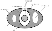
図2は、カテーテル1の断面構造を模式的に示す図である。ここでは、バルーン設置部21基端側における断面構造を例に挙げて示した。 FIG. 2 is a diagram schematically showing a cross-sectional structure of the catheter 1. Here, the cross-sectional structure at the base end side of the balloon installation portion 21 is shown as an example.
本体チューブ2は、断面楕円形状を有している。本体チューブ2内には、第1ルーメン23が設けられ、その両脇に、第2ルーメン24および第3ルーメン25が配置されている。各ルーメンは、本体チューブ2の基端側から先端側に貫通するように設けられ、基端側において開口している。第1ルーメン23は、腸内の内容物を体外に排出するための通路となる。第2ルーメン24は、バルーンに膨張用流体を注入する役割を果たす。第3ルーメン25は、吸引効率の向上と、腸壁に対する過度の吸引を防止するためのエアー導入通路としての役割を果たす。ガイドワイヤー20は、第1ルーメン23の内部を挿通するように設けられている。本体チューブ2の外側面、第1ルーメン23の内側面およびガイドワイヤー20の外側面には、潤滑剤層22が設けられている。本体チューブ2は、その側面の一部にX線不透過ライン26が設けられているが、それ以外の部分はX線を透過する材料により構成されている。
The main body tube 2 has an elliptical cross section. A first lumen 23 is provided in the main body tube 2, and a second lumen 24 and a third lumen 25 are disposed on both sides thereof. Each lumen is provided so as to penetrate from the proximal end side of the main body tube 2 to the distal end side, and is open at the proximal end side. The first lumen 23 becomes a passage for discharging the contents in the intestine to the outside of the body. The second lumen 24 serves to inject inflation fluid into the balloon. The third lumen 25 serves as an air introduction passage for improving suction efficiency and preventing excessive suction on the intestinal wall. The
図3は、カテーテル1の先端部の断面詳細構造を示す図である。先端側から、誘導部4、視認部16、バルーン設置部21がこの順で設けられている。視認部16は、目視およびX線を用いた観察により、本体チューブ2内部の様子を確認できる構成となっている。なお、本実施形態においては、視認部16の長さは15mm程度である。 FIG. 3 is a view showing a detailed cross-sectional structure of the distal end portion of the catheter 1. From the front end side, the guide part 4, the visual recognition part 16, and the balloon installation part 21 are provided in this order. The visual recognition unit 16 has a configuration in which a state inside the main body tube 2 can be confirmed by visual observation and observation using X-rays. In the present embodiment, the length of the visual recognition part 16 is about 15 mm.
図3には示していないが、図5に示した第1ルーメン23は、カテーテル1の基端側から視認部16にわたって設けられ、このルーメンの内部に、予めガイドワイヤー20が挿入されている。ガイドワイヤー20の先端位置は、誘導部4の後端部からバルーン設置部21の間に設けられた、長さ15mm程度の視認部16に位置している。このような配置とすることにより、ガイドワイヤー20の先端位置を体外では視覚的に確認でき、使用前にガイドワイヤー20の位置調整を行うことなく即座に使用できる。また、体内での先端位置を確認することもできる。ガイドワイヤー先端位置が、視認部16の外にあると、先端位置を確認することが難しくなる。これは、誘導部4、バルーン3およびバルーン設置部21が造影剤を含有しているため、これらの領域にガイドワイヤー20の先端がある場合、造影の際に同化してしまうため、先端位置を確認することが困難となりやすい。
Although not shown in FIG. 3, the first lumen 23 shown in FIG. 5 is provided from the proximal end side of the catheter 1 to the viewing portion 16, and the
以上説明したように、本実施形態のカテーテル1は、体内誘導用のガイドワイヤー20が予めカテーテルのルーメン内に挿入されている。従来、処置前にカテーテル1の剛性を向上させるため、カテーテル1内にガイドワイヤー20を複数人により挿入一体化させる操作が必要であったが、予めガイドワイヤー20がカテーテルのルーメン内に挿入されているため、処置前の煩雑な操作が無く、緊急を要する腸閉塞の処置において即座に術者が一人で操作を行うことが可能となる。
また、本実施形態のカテーテル1では、注液ポート14から食塩水を導入するように構成されているため、良好な操作性が得られる。従来は、カテーテル基端側からガイドワイヤー保護用のケース内で食塩水を注水して使用するよう構造となっていたため、カテーテル基端側の把持部も濡れてしまうことが多かった。ところが、カテーテルの外壁には潤滑剤が塗ってあるので、食塩水と触れることにより滑りやすい状態になり、操作性が著しく低下することがあった。本実施形態では、このような操作性の低下を防止することができる。
As described above, in the catheter 1 of the present embodiment, the
In addition, since the catheter 1 of the present embodiment is configured to introduce saline from the liquid injection port 14, good operability can be obtained. Conventionally, the structure is such that saline is poured into the guide wire protecting case from the proximal side of the catheter, so that the gripping portion on the proximal side of the catheter often gets wet. However, since the outer wall of the catheter is coated with a lubricant, it may become slippery when touched with saline, and the operability may be significantly reduced. In this embodiment, such a decrease in operability can be prevented.
第二の実施の形態
本実施形態では、カテーテルを収容したカテーテル収容体の構成例について説明する。カテーテルの構造は第一の実施の形態で説明したものと同様である。カテーテル1には、先端側から、誘導部4、視認部16、バルーン設置部21がこの順で設けられている。視認部16は、目視およびX線を用いた観察により本体チューブ2内部の様子を確認できる構成となっている。カテーテル1の基端側から視認部16にわたって設けられたルーメンの内部に、予めガイドワイヤー20が挿入されている。ガイドワイヤー20の先端は視認部16に位置している。
Second Embodiment In this embodiment, a configuration example of a catheter container that accommodates a catheter will be described. The structure of the catheter is the same as that described in the first embodiment. The catheter 1 is provided with a guide portion 4, a visual recognition portion 16, and a balloon installation portion 21 in this order from the distal end side. The visual recognition unit 16 is configured to be able to confirm the state inside the main body tube 2 by visual observation and observation using X-rays. A
図4は、カテーテル1を収容した収容体45を示す図である。この収容体45は、カテーテル1の収容される滅菌袋40と、シリンジ30の収容されたシリンジ収容部を有する。シリンジ30は、バルーン拡張用あるいは造影剤注入用として用いられるものである。シリンジ30はエチレンオキサイドガスの透過しない素材により構成される。 FIG. 4 is a view showing a container 45 that houses the catheter 1. The container 45 includes a sterilization bag 40 in which the catheter 1 is accommodated and a syringe accommodating portion in which the syringe 30 is accommodated. The syringe 30 is used for balloon expansion or for contrast medium injection. The syringe 30 is made of a material that does not transmit ethylene oxide gas.
ガイドワイヤー20は、カテーテル1内のルーメン(不図示)に予め挿入されている。ガイドワイヤー20は、カテーテル基端側に設けられた注液コネクター11から延出している。
The
カテーテル1は、所定の巻き径で巻かれた状態で収容されている。一方、ガイドワイヤー20の延出部分は、(不図示)のテープにより固定化され、上記所定の巻き径よりも小さい巻き径で巻かれた状態で収容されている。こうすることにより、ガイドワイヤー20の延出部分がカテーテル1の他の部分と接触し損傷を与えることを防止している。
The catheter 1 is housed in a state of being wound with a predetermined winding diameter. On the other hand, the extended portion of the
シリンジ30には予め滅菌蒸留水を充填し、バルーン拡張用としてすぐに利用できる形態とすることができる。また、シリンジ30内に造影剤を注入し、造影剤注入用としてすぐに利用できる形態としてもよい。こうすることにより、即座に使用可能な緊急用キットとして利用可能となる。 The syringe 30 can be filled with sterilized distilled water in advance and can be used immediately for balloon expansion. Moreover, it is good also as a form which inject | pours a contrast agent in the syringe 30 and can utilize immediately for contrast agent injection | pouring. By doing so, it can be used as an emergency kit that can be used immediately.
これら構成品の包装状態における配置は、ガイドワイヤー20の先端柔軟部の損傷を防ぐためにカテーテルの先端からは突出しないように配置し、必然的に術者が把持するガイドワイヤー20の後端部は、カテーテル末端の注液コネクター11の後端から突出させておくこととなる。包装材料は、図3のように滅菌袋に直接配しても、トレー等を使用してもよく特に限定されるものではない。
The arrangement of these components in the packaged state is arranged so as not to protrude from the distal end of the catheter in order to prevent damage to the distal flexible portion of the
次に、カテーテル1の使用方法を説明する。先ず、滅菌袋40を開封して一体となったカテーテル1、注液コネクター11、ガイドワイヤー20を取り出し、前準備として注液コネクター11の注液ポート14よりシリンジ30にて潤滑剤を注入する。なお、潤滑剤としては、一般的にオリーブオイルが多く使用されるが、カテーテル内腔またはガイドワイヤー20の表面にハイドロゲルのコーティングがなされている場合には、滅菌生理食塩水等が使用される。
Next, a method for using the catheter 1 will be described. First, the sterilization bag 40 is opened and the catheter 1, the injection connector 11, and the
以降の鼻腔からの挿入操作は、従来どおり、ガイドワイヤー20先端位置とカテーテル先端位置を調整しながらなされ、目的の腸閉塞部位まで到達せしめ、その後は注液コネクター11およびガイドワイヤー20を取り外し、種々の吸引器、排液貯留容器と接続して留置完了となる。
The subsequent insertion operation from the nasal cavity is performed while adjusting the distal end position of the
第三の実施の形態
本実施形態では、カテーテルを収容したカテーテル収容体の構成例について説明する。カテーテルの構造は第一の実施の形態で説明したものと同様である。カテーテル1には、先端側から、誘導部4、視認部16、バルーン設置部21がこの順で設けられている。視認部16は、目視およびX線を用いた観察により本体チューブ2内部の様子を確認できる構成となっている。カテーテル1の基端側から視認部16にわたって設けられたルーメンの内部に、予めガイドワイヤー20が挿入されている。ガイドワイヤー20の先端は視認部16に位置している。
Third Embodiment In this embodiment, a configuration example of a catheter container that accommodates a catheter will be described. The structure of the catheter is the same as that described in the first embodiment. The catheter 1 is provided with a guide portion 4, a visual recognition portion 16, and a balloon installation portion 21 in this order from the distal end side. The visual recognition unit 16 is configured to be able to confirm the state inside the main body tube 2 by visual observation and observation using X-rays. A
図5は、製品トレー50にカテーテル1を収納した収納体55の概略構造を示す図である。製品トレー50の内部には、平面視において円形形状を有する収容室56が設けられており、この収容室56にカテーテル1が収容されている。
FIG. 5 is a diagram showing a schematic structure of a
収容室56内には、チューブ抑え51が設けられている。チューブ抑え51は、チューブ2を束ねた状態で固定化する。
A tube retainer 51 is provided in the
また、収容室56内には、リブ52が設けられており、これにより、バルーン3及び誘導部4を含むカテーテル先端部が、カテーテルの他の部分から離れた位置に固定化されるようになっている。
In addition, a rib 52 is provided in the
この収容体は、カテーテル1を巻いた状態で収容するものであるが、このようにした場合、バルーン3及びチューブ先端誘導部4が輸送時にチューブと接触して擦れることにより損傷する可能性がある。そこで本実施形態では、カテーテル1を所定の巻き径で巻いた状態とするとともに、バルーン3及びチューブ先端誘導部4を含むカテーテル先端部を、上記所定の巻き径よりも小さい巻き径で巻いた状態とする。すなわち、カテーテルの束ねられた部分の曲率半径と、カテーテル先端部分の曲率半径とが異なるように配置され、カテーテルの先端部と基端部とは、それぞれ一致しないように、かつ、カテーテルの束ねられた部分と接触しないように、配置されている。具体的には、製品トレー50の内側にリブ52を設けており、これにより、カテーテル先端部を内側に配置させカテーテルの他の部分と接触しないようにしている。このような構成とすることで、バルーン3およびチューブ先端誘導部4の損傷防止が図られている。 This container accommodates the catheter 1 in a wound state, but in this case, the balloon 3 and the tube tip guide 4 may be damaged by contacting and rubbing with the tube during transportation. . Therefore, in this embodiment, the catheter 1 is wound with a predetermined winding diameter, and the catheter tip including the balloon 3 and the tube tip guide 4 is wound with a winding diameter smaller than the predetermined winding diameter. And That is, the radius of curvature of the bundled portion of the catheter and the radius of curvature of the distal end portion of the catheter are arranged to be different, and the distal end portion and the proximal end portion of the catheter do not coincide with each other and the catheter bundles are bundled. It is arranged so that it does not come into contact with any part. Specifically, a rib 52 is provided on the inner side of the product tray 50, so that the distal end portion of the catheter is arranged on the inner side so that it does not come into contact with other portions of the catheter. By adopting such a configuration, damage prevention of the balloon 3 and the tube tip guiding portion 4 is achieved.
カテーテル1の巻き径は、ガイドワイヤー20やカテーテル1の内部構造に、変形や表面樹脂層の損傷が発生しない範囲とする。カテーテル1内にガイドワイヤー20が挿入された状態で巻くと、カテーテル1内腔壁面にガイドワイヤー20からの応力が掛かることによりカテーテル1の内腔に変形が生じ、第1〜3のルーメンの内腔が潰れてしまうことが懸念される。このため、外径53は、200〜350mmが好ましく、内径54は、100〜200mmで巻き、収納するのが好ましい。この範囲であれば、ガイドワイヤーに異常な力がかかりにくく、表面がこすれて潤滑性処理層が傷つくことが少ない。
The wound diameter of the catheter 1 is set within a range in which the
また、製品トレー50における注液コネクター11の配置は、カテーテル1の吸引ルーメン用コネクターに接続しておいても良いが、即座に接続できれば離した位置に配置しても良い。いずれもガイドワイヤー20に通した状態にしておくことが好ましい。カテーテル1の吸引ルーメン用コネクターが塩化ビニル樹脂やポリウレタン樹脂等の熱可塑性樹脂では嵌めた状態により、コネクターが変形する可能性があるため、カテーテル1の吸引ルーメン用コネクターには接続せず、離した位置に製品トレー上で配置することが好ましい。シリコーンゴム等の熱硬化性樹脂では嵌めておいても変形は進まないため、嵌合した状態で包装することが好ましい。
In addition, the liquid injection connector 11 in the product tray 50 may be connected to the suction lumen connector of the catheter 1, but may be arranged in a separated position if it can be immediately connected. In any case, it is preferable that the
以上、図面を参照して本発明の実施形態について述べたが、これらは本発明の例示であり、上記以外の様々な構成を採用することもできる。 As mentioned above, although embodiment of this invention was described with reference to drawings, these are the illustrations of this invention, Various structures other than the above are also employable.
たとえば、ガイドワイヤー20の延出部分は、たとえば樹脂製保護チューブ等の保護部材により覆ってもよい。ガイドワイヤー20の表面には、潤滑剤の塗布層が設けられている。保護部材を設けることにより、この塗布層が好適に保護される。
For example, the extending portion of the
1 医療用カテーテル
2 本体チューブ
3 バルーン
4 誘導部
5 金属球
6 吸引孔
7 分岐チューブ
8 コネクターA
9 コネクターB
10 一方弁
11 注液コネクター
12 本体
13 ガイドワイヤー固定部
14 注液ポート
15 弾性体
16 視認部
20 ガイドワイヤー
21 バルーン設置部
22 潤滑性処理部
23 第1ルーメン
24 第2ルーメン
25 第3ルーメン
26 X線不透過ライン
30 シリンジ
40 滅菌袋
50 製品トレー
51 チューブ抑えウイング
52 リブ
53 外径
54 内径
DESCRIPTION OF SYMBOLS 1 Medical catheter 2 Main body tube 3 Balloon 4
9 Connector B
DESCRIPTION OF SYMBOLS 10 One-way valve 11 Injection connector 12 Main body 13 Guide wire fixing | fixed part 14 Injection port 15 Elastic body 16
Claims (11)
前記腸閉塞処置用カテーテルを収容する容器と、
を含み、
前記容器から取り出された前記腸閉塞処置用カテーテルの前記ルーメンの内部に潤滑剤を注入して使用することを特徴とするカテーテル収納体。 An intestinal obstruction treatment catheter having a lumen inside, and a guide wire inserted into the lumen;
A container for housing the intestinal obstruction treatment catheter;
Only including,
A catheter housing body that is used by injecting a lubricant into the lumen of the intestinal obstruction treatment catheter taken out of the container .
前記腸閉塞処置用カテーテルが、所定の径で巻かれた状態で束ねられているカテーテル収納体。 The catheter housing according to claim 1,
A catheter housing body in which the intestinal obstruction treatment catheter is bundled in a wound state with a predetermined diameter.
前記腸閉塞処置用カテーテルは;
目視およびX線を用いた観察により、カテーテル内部を視認できるように構成された視認部と、
前記視認部のカテーテル基端側に設けられたバルーンと、
をさらに備え、
前記ガイドワイヤーの先端部が、前記視認部に位置するカテーテル収納体。 The catheter housing according to claim 2,
The intestinal obstruction treatment catheter is;
A visual recognition unit configured to visually recognize the inside of the catheter by visual observation and observation using X-rays; and
A balloon provided on the catheter proximal side of the visual recognition unit;
Further comprising
A catheter housing body in which a distal end portion of the guide wire is located in the visual recognition portion.
前記視認部の、カテーテル先端側に設けられ、前記カテーテルを体内に誘導する役割を果たすように構成された誘導部をさらに備えるカテーテル収納体。 The catheter housing according to claim 3,
A catheter housing body further comprising a guide portion provided on the distal end side of the visual recognition portion and configured to guide the catheter into the body.
前記誘導部および前記バルーンが、前記腸閉塞処置用カテーテルの束ねられた部分と接触しないように配置されているカテーテル収納体。 The catheter housing according to claim 4,
A catheter housing body in which the guiding portion and the balloon are arranged so as not to contact a bundled portion of the catheter for intestinal obstruction treatment.
前記ガイドワイヤーがカテーテル基端部から延出しているカテーテル収納体。 The catheter housing body according to any one of claims 1 to 5,
A catheter housing body in which the guide wire extends from the proximal end portion of the catheter.
前記ガイドワイヤーの延出部分が、保護部材により覆われているカテーテル収納体。 The catheter housing according to claim 6,
A catheter housing body in which an extended portion of the guide wire is covered with a protective member.
前記カテーテルの先端部と基端部とが、前記腸閉塞処置用カテーテルの束ねられた部分と接触しないように配置されているカテーテル収納体。 The catheter housing according to claim 2,
A catheter housing body arranged such that a distal end portion and a proximal end portion of the catheter do not come into contact with a bundled portion of the catheter for intestinal obstruction treatment.
前記腸閉塞処置用カテーテルが液体注入部をさらに備えるカテーテル収納体。 A catheter housing body according to any one of claims 1 to 8,
The catheter housing body in which the catheter for intestinal obstruction treatment further includes a liquid injection part.
前記腸閉塞処置用カテーテルにおいて、カテーテル基端側にガイドワイヤー固定部、カテーテル先端側にコネクター接続部、注入液ポートを備える分岐注液コネクターが、前記ガイドワイヤーが挿入されている前記ルーメンの末端に予め接続されている、カテーテル収納体。 The catheter housing body according to any one of claims 1 to 9,
In the intestinal obstruction treatment catheter, a branch injection connector having a guide wire fixing part on the proximal side of the catheter, a connector connection part on the distal end side of the catheter, and an infusion solution port is provided in advance at the end of the lumen into which the guide wire is inserted Connected catheter housing.
前記ガイドワイヤーに潤滑性処理が施されているカテーテル収納体。 A catheter housing body according to any one of claims 1 to 10,
A catheter housing body in which the guide wire is lubricated.
Priority Applications (1)
| Application Number | Priority Date | Filing Date | Title |
|---|---|---|---|
| JP2004203928A JP4593186B2 (en) | 2003-07-09 | 2004-07-09 | Catheter housing |
Applications Claiming Priority (2)
| Application Number | Priority Date | Filing Date | Title |
|---|---|---|---|
| JP2003194064 | 2003-07-09 | ||
| JP2004203928A JP4593186B2 (en) | 2003-07-09 | 2004-07-09 | Catheter housing |
Related Child Applications (1)
| Application Number | Title | Priority Date | Filing Date |
|---|---|---|---|
| JP2008117395A Division JP4787974B2 (en) | 2003-07-09 | 2008-04-28 | Catheter housing |
Publications (3)
| Publication Number | Publication Date |
|---|---|
| JP2005040599A JP2005040599A (en) | 2005-02-17 |
| JP2005040599A5 JP2005040599A5 (en) | 2007-08-23 |
| JP4593186B2 true JP4593186B2 (en) | 2010-12-08 |
Family
ID=34277237
Family Applications (1)
| Application Number | Title | Priority Date | Filing Date |
|---|---|---|---|
| JP2004203928A Active JP4593186B2 (en) | 2003-07-09 | 2004-07-09 | Catheter housing |
Country Status (1)
| Country | Link |
|---|---|
| JP (1) | JP4593186B2 (en) |
Families Citing this family (22)
| Publication number | Priority date | Publication date | Assignee | Title |
|---|---|---|---|---|
| JP2008012196A (en) * | 2006-07-07 | 2008-01-24 | Hi-Lex Corporation | Board and package set for medical long scroll |
| JP4710793B2 (en) * | 2006-10-27 | 2011-06-29 | 住友ベークライト株式会社 | Medical catheter set |
| JP5332184B2 (en) * | 2007-11-16 | 2013-11-06 | 住友ベークライト株式会社 | Intestinal insertion catheter |
| GB2465334B (en) * | 2008-10-31 | 2013-02-13 | Daniela Andrich | Catheterisation device |
| US8663190B2 (en) | 2011-04-22 | 2014-03-04 | Ablative Solutions, Inc. | Expandable catheter system for peri-ostial injection and muscle and nerve fiber ablation |
| US9237925B2 (en) | 2011-04-22 | 2016-01-19 | Ablative Solutions, Inc. | Expandable catheter system for peri-ostial injection and muscle and nerve fiber ablation |
| US20130053792A1 (en) | 2011-08-24 | 2013-02-28 | Ablative Solutions, Inc. | Expandable catheter system for vessel wall injection and muscle and nerve fiber ablation |
| US9056185B2 (en) | 2011-08-24 | 2015-06-16 | Ablative Solutions, Inc. | Expandable catheter system for fluid injection into and deep to the wall of a blood vessel |
| US10736656B2 (en) | 2012-10-29 | 2020-08-11 | Ablative Solutions | Method for painless renal denervation using a peri-vascular tissue ablation catheter with support structures |
| US10945787B2 (en) | 2012-10-29 | 2021-03-16 | Ablative Solutions, Inc. | Peri-vascular tissue ablation catheters |
| US9526827B2 (en) | 2012-10-29 | 2016-12-27 | Ablative Solutions, Inc. | Peri-vascular tissue ablation catheter with support structures |
| US9301795B2 (en) | 2012-10-29 | 2016-04-05 | Ablative Solutions, Inc. | Transvascular catheter for extravascular delivery |
| US10226278B2 (en) | 2012-10-29 | 2019-03-12 | Ablative Solutions, Inc. | Method for painless renal denervation using a peri-vascular tissue ablation catheter with support structures |
| US9554849B2 (en) | 2012-10-29 | 2017-01-31 | Ablative Solutions, Inc. | Transvascular method of treating hypertension |
| US10881458B2 (en) | 2012-10-29 | 2021-01-05 | Ablative Solutions, Inc. | Peri-vascular tissue ablation catheters |
| US10517666B2 (en) | 2013-10-25 | 2019-12-31 | Ablative Solutions, Inc. | Apparatus for effective ablation and nerve sensing associated with denervation |
| US9931046B2 (en) | 2013-10-25 | 2018-04-03 | Ablative Solutions, Inc. | Intravascular catheter with peri-vascular nerve activity sensors |
| US9949652B2 (en) | 2013-10-25 | 2018-04-24 | Ablative Solutions, Inc. | Apparatus for effective ablation and nerve sensing associated with denervation |
| WO2016088774A1 (en) * | 2014-12-02 | 2016-06-09 | テルモ株式会社 | Catheter holder, and catheter set |
| JP6316238B2 (en) * | 2015-05-28 | 2018-04-25 | 日本ライフライン株式会社 | Balloon catheter |
| WO2018216049A1 (en) * | 2017-05-22 | 2018-11-29 | オリンパス株式会社 | Medical sheath |
| US10849685B2 (en) | 2018-07-18 | 2020-12-01 | Ablative Solutions, Inc. | Peri-vascular tissue access catheter with locking handle |
Family Cites Families (11)
| Publication number | Priority date | Publication date | Assignee | Title |
|---|---|---|---|---|
| JPH0340311Y2 (en) * | 1986-03-31 | 1991-08-23 | ||
| JPH0314192Y2 (en) * | 1986-06-12 | 1991-03-29 | ||
| JPH0316681Y2 (en) * | 1987-07-20 | 1991-04-10 | ||
| JPH01170475A (en) * | 1987-12-25 | 1989-07-05 | Terumo Corp | Guide wire for catheter |
| CA2036285A1 (en) * | 1990-02-14 | 1991-08-15 | Gary H. Miller | Balloon catheter for dilating a prostratic urethra |
| JP2559372Y2 (en) * | 1992-11-12 | 1998-01-14 | 株式会社八光電機製作所 | Guide wire insertion device |
| JPH0951954A (en) * | 1995-08-15 | 1997-02-25 | Nippon Zeon Co Ltd | Wire guide fixture and catheter set having the fixture |
| EP0782868A1 (en) * | 1996-01-08 | 1997-07-09 | Schneider (Europe) Ag | Packing system |
| US5776115A (en) * | 1996-01-17 | 1998-07-07 | Becton Dickinson And Company | Catheter having a gear-shaped lumen to avert the elimination of fluid flow therein |
| JPH09225037A (en) * | 1996-02-28 | 1997-09-02 | Nippon Zeon Co Ltd | Dispenser for guide wire |
| US5848691A (en) * | 1997-07-07 | 1998-12-15 | Wilson-Cook Medical Inc. | Package for sphincterotome or catheter including structure maintaining shape of distal tip |
-
2004
- 2004-07-09 JP JP2004203928A patent/JP4593186B2/en active Active
Also Published As
| Publication number | Publication date |
|---|---|
| JP2005040599A (en) | 2005-02-17 |
Similar Documents
| Publication | Publication Date | Title |
|---|---|---|
| JP4593186B2 (en) | Catheter housing | |
| JP5263343B2 (en) | Catheter housing | |
| US20210308422A1 (en) | Manipulatable delivery catheter for occlusive devices | |
| AU613155B2 (en) | Catheter tube and endoscope | |
| AU730940B2 (en) | Methods and systems for deployment of a detachable balloon at a target site in vivo | |
| US6726700B1 (en) | Manipulatable delivery catheter for occlusive devices | |
| US20040006305A1 (en) | Balloon catheter having an expandable distal end | |
| US20090208368A1 (en) | Urinary catheter, catheter packaging assembly and method of use | |
| US7229433B2 (en) | Apparatus for treating pneumothorax and/or hemothorax | |
| JP2002360702A (en) | Catheter and method for manufacturing the same | |
| JP2009112530A (en) | Medical instrument | |
| JPWO2004067080A1 (en) | Endoscope-equipped puncture balloon | |
| US11744611B2 (en) | Puncture system | |
| JP2013527001A (en) | Balloon catheter | |
| JP4710793B2 (en) | Medical catheter set | |
| JP4695104B2 (en) | Gastrointestinal treatment / test tool | |
| JP2020506021A (en) | Non-vascular guide wire | |
| JP2010213800A (en) | Catheter | |
| JP5332184B2 (en) | Intestinal insertion catheter | |
| CN107550534A (en) | Direct motion descending aorta balloon occlusion device | |
| JPH06181879A (en) | Endoscope | |
| JP2001190685A (en) | Connector for fixing guide wire | |
| US20110208117A1 (en) | Catheter | |
| JP3489127B2 (en) | Balloon catheter set and balloon package used for it | |
| JP2533839Y2 (en) | Medical catheter |
Legal Events
| Date | Code | Title | Description |
|---|---|---|---|
| A521 | Written amendment |
Free format text: JAPANESE INTERMEDIATE CODE: A523 Effective date: 20070705 |
|
| A621 | Written request for application examination |
Free format text: JAPANESE INTERMEDIATE CODE: A621 Effective date: 20070705 |
|
| A871 | Explanation of circumstances concerning accelerated examination |
Free format text: JAPANESE INTERMEDIATE CODE: A871 Effective date: 20070817 |
|
| A975 | Report on accelerated examination |
Free format text: JAPANESE INTERMEDIATE CODE: A971005 Effective date: 20070905 |
|
| A131 | Notification of reasons for refusal |
Free format text: JAPANESE INTERMEDIATE CODE: A131 Effective date: 20071204 |
|
| A521 | Written amendment |
Free format text: JAPANESE INTERMEDIATE CODE: A523 Effective date: 20080201 |
|
| A02 | Decision of refusal |
Free format text: JAPANESE INTERMEDIATE CODE: A02 Effective date: 20080304 |
|
| A521 | Written amendment |
Free format text: JAPANESE INTERMEDIATE CODE: A523 Effective date: 20080428 |
|
| A911 | Transfer of reconsideration by examiner before appeal (zenchi) |
Free format text: JAPANESE INTERMEDIATE CODE: A911 Effective date: 20080613 |
|
| A912 | Removal of reconsideration by examiner before appeal (zenchi) |
Free format text: JAPANESE INTERMEDIATE CODE: A912 Effective date: 20080822 |
|
| A521 | Written amendment |
Free format text: JAPANESE INTERMEDIATE CODE: A523 Effective date: 20100818 |
|
| A01 | Written decision to grant a patent or to grant a registration (utility model) |
Free format text: JAPANESE INTERMEDIATE CODE: A01 |
|
| A61 | First payment of annual fees (during grant procedure) |
Free format text: JAPANESE INTERMEDIATE CODE: A61 Effective date: 20100915 |
|
| FPAY | Renewal fee payment (event date is renewal date of database) |
Free format text: PAYMENT UNTIL: 20130924 Year of fee payment: 3 |
|
| R150 | Certificate of patent or registration of utility model |
Ref document number: 4593186 Country of ref document: JP Free format text: JAPANESE INTERMEDIATE CODE: R150 Free format text: JAPANESE INTERMEDIATE CODE: R150 |
|
| FPAY | Renewal fee payment (event date is renewal date of database) |
Free format text: PAYMENT UNTIL: 20130924 Year of fee payment: 3 |
|
| FPAY | Renewal fee payment (event date is renewal date of database) |
Free format text: PAYMENT UNTIL: 20140924 Year of fee payment: 4 |