JP4592884B2 - Image display device having three-dimensional eccentric optical path - Google Patents
Image display device having three-dimensional eccentric optical path Download PDFInfo
- Publication number
- JP4592884B2 JP4592884B2 JP2000228737A JP2000228737A JP4592884B2 JP 4592884 B2 JP4592884 B2 JP 4592884B2 JP 2000228737 A JP2000228737 A JP 2000228737A JP 2000228737 A JP2000228737 A JP 2000228737A JP 4592884 B2 JP4592884 B2 JP 4592884B2
- Authority
- JP
- Japan
- Prior art keywords
- optical path
- image display
- plane
- display element
- prism
- Prior art date
- Legal status (The legal status is an assumption and is not a legal conclusion. Google has not performed a legal analysis and makes no representation as to the accuracy of the status listed.)
- Expired - Fee Related
Links
Images


Landscapes
- Optical Elements Other Than Lenses (AREA)
- Lenses (AREA)
Description
【0001】
【発明の属する技術分野】
本発明は、3次元偏心光路を備えた画像表示装置に関し、特に、観察者の頭部又は顔面に保持することを可能にする頭部又は顔面装着式画像表示装置に関する。
【0002】
【従来の技術】
従来、左右眼共通の単一の画像表示素子を用いた頭部装着式画像表示装置として、特開平6−110013号においては、画像表示素子からの表示光を観察者の左右の眼へ導くために、二等辺三角柱のプリズムとミラーで分割し、折り曲げている。この配置においては、諸収差の補正は、観察者の眼の瞳の前に配置するレンズで行うことになり、補正が難しくなると同時に、装置の大型化を招く。
【0003】
また、特開平7−287185号においては、ミラーを複数枚使用し、凸レンズ1枚で結像作用を行っている。そのため、組み立て調整が非常に難しく、また適切な性能を達成できない。また、画像表示素子が3次元的に配置してあるが、左右の映像が逆に回転してしまう。
【0004】
また、特開平9−61748号のものにおいては、画像表示素子からの表示光をハーフミラーを利用して分割して両眼で観察している。そのために左右それぞれの眼球へ表示光が分かれるので、観察像強度が弱く暗くなる。
【0005】
また、特開平9−181998号、特開平9−181999号のものは、左右別々あるいは共通の反射プリズム光学系を用いるものであるが、画角が狭いと言う問題がある。
【0006】
さらに、特表平10−504115号のものは、ハーフミラーを利用して表示光を分割するものであるが、部品点数が非常に多く、組み立てが非常に複雑である。
【0007】
なお、本出願人は、特願2000−48750号等において、中央に光路振り分け光学系を配置し、その左右に接眼プリズムを配置した頭部装着式等の画像表示装置を提案している。
【0008】
【発明が解決しようとする課題】
本発明は従来技術のこのような問題点に鑑みてなされたものであり、その目的は、1つの画像表示素子からの映像を、ハーフミラーを利用せずに両眼に導き、明るく観察でき、さらに、中央に配置する光路振り分け光学系にパワーを持たせることで、諸収差の補正を容易にした頭部装着式画像表示装置等の画像表示装置を提供することである。
【0009】
さらには、本出願人による特願2000−48750号等のような画像表示装置をさらに広画角化することを目的とするものである。
【0010】
【課題を解決するための手段】
上記目的を達成する本発明の3次元偏心光路を備えた画像表示装置は、観察画像を画像表示部に形成する画像表示素子と、前記画像表示素子が形成した画像を観察者眼球位置に相当する瞳に導く観察光学系とを含んだ画像表示装置において、
前記画像表示素子が、複数の画素を単板上に並設させた1枚の画像表示素子を有して構成され、
前記1枚の画像表示素子の少なくとも中央部分に位置する各画素が、観察者の左右の眼球に光束を導けるような射出角度で画像光束を放射するように構成され、
前記観察光学系が、少なくとも、観察者の左眼に光束を導く左接眼部と、観察者の右眼に光束を導く右接眼部と、前記画像表示素子から前記射出角度を持って放射された画像光束を前記左右の接眼部に導く3次元光路振り分け部とを含み、
前記左接眼部が、少なくとも2面以上の反射面を有し、その中の少なくとも1つの反射面が偏心収差補正機能を有した回転非対称な曲面反射面にて構成され、
前記右接眼部が、少なくとも2面以上の反射面を有し、その中の少なくとも1つの反射面が偏心収差補正機能を有した回転非対称な曲面反射面にて構成され、
前記左接眼部の有する前記2面以上の反射面にて形成される軸上主光線の偏心光路面(Y−Z面)と、前記右接眼部の有する前記2面以上の反射面にて形成される軸上主光線の偏心光路面(Y−Z面)とが、略同一平面(Y−Z面)に形成されるように、前記左右接眼部が構成され、
前記3次元光路振り分け部は、左右対称な光路を形成できるように、左右対称に光学面が配置され、かつ、前記光学面の中、少なくとも左右2組の反射面が、前記左右の接眼部によって形成される偏心光路面(Y−Z面)に対して垂直な方向(X方向)の成分をも含めた3次元偏心方向に左右各々の光束の軸上主光線を反射させるように構成されていることを特徴とするものである。
【0011】
以下、本発明において、上記構成をとる理由と作用を説明する。
【0012】
通常、人間の瞳の間隔は平均約64mm程度と言われ、個人差がある。そのため、両眼観察用の観察光学系において、眼幅の個人差を観察光学系で吸収するためには、予め光学系の瞳を横長に設定することが好ましい。つまり、観察光学系の瞳は観察者の水平方向に長い楕円(あるいは長方形等)を用いることが好ましい。
【0013】
そのとき、瞳の長手方向と接眼部の偏心方向を同一方向にすると、各反射面の有効面は必然的に横に長い有効径を確保する必要がある。しかし、特願2000−48750号のように、観察者の水平方向にのみ偏心させた光学系の場合、人間の眼幅による制約があるため、光学系を横方向に大きくすることはできない。したがって、観察画角を広くすると、光路振り分け部の反射面を両眼の接眼部の間に配置することが困難になってくる。
【0014】
そこで、本発明の画像表示装置の観察光学系では、光路振り分け部内全体の光路を3次元的な構成にすることで、光路振り分け部内の反射面を垂直方向に配置するようにして、画角を広くした場合でも、両眼の反射面の有効径を確保できるようにしたものである。
【0015】
なお、観察光学系を構成する左右の接眼部、3次元光路振り分け部それぞれを反射鏡のみで構成しても、左右の接眼部、3次元光路振り分け部それぞれを偏心プリズムで構成しても、また、左右の接眼部と3次元光路振り分け部を一体の偏心プリズムで構成してもよい。
【0016】
そして、3次元光路振り分け部は、偏心収差補正機能を有した回転非対称な曲面形状の反射面を少なくとも1組備えていることが望ましい。
【0017】
その場合、その少なくとも1組の偏心収差補正機能を有した回転非対称な曲面形状の反射面は、3次元偏心方向に左右各々の光束の軸上主光線を反射させる少なくとも左右2組の反射面の中の1組に配置されていることが望ましい。
【0018】
また、その少なくとも1組の偏心収差補正機能を有した回転非対称な曲面形状の反射面は、対称面を1面のみ有する自由曲面にて形成され、その少なくとも1組の自由曲面の各々の唯一の対称面が同一平面内に一致するように構成されていることが望ましい。
【0019】
ここで、回転非対称な曲面形状の面として、本発明では代表的に自由曲面を使用するが、自由曲面とは以下の式で定義されるものである。この定義式のZ軸が自由曲面の軸となる。
【0020】

【0021】
球面項中、
c:頂点の曲率
k:コーニック定数(円錐定数)
r=√(X2 +Y2 )
である。
【0022】
自由曲面項は、
【0023】
上記自由曲面は、一般的には、X−Z面、Y−Z面共に対称面を持つことはないが、Xの奇数次項を全て0にすることによって、Y−Z面と平行な対称面が1つだけ存在する自由曲面となる。また、Yの奇数次項を全て0にすることによって、X−Z面と平行な対称面が1つだけ存在する自由曲面となる。
【0024】
また、上記の回転非対称な曲面形状の面である自由曲面の他の定義式として、Zernike多項式により定義できる。この面の形状は以下の式(b)により定義する。その定義式(b)のZ軸がZernike多項式の軸となる。回転非対称面の定義は、X−Y面に対するZの軸の高さの極座標で定義され、RはX−Y面内のZ軸からの距離、AはZ軸回りの方位角で、X軸から測った回転角で表せられる。
【0025】
【0026】
上記定義式は、回転非対称な曲面形状の面の例示のために示したものであり、他のいかなる定義式に対しても同じ効果が得られることは言うまでもない。
【0027】
なお、自由曲面の他の定義式の例として、次の定義式(c)があげられる。
【0028】
Z=ΣΣCnmXY
例として、k=7(7次項)を考えると、展開したとき、以下の式で表せる。
【0029】
【0030】
また、本発明においては、前記のように、観察光学系をプリズム部材にて形成し、反射面の何れもがプリズム部材の表面に形成された裏面反射面にて構成するようにしてもよい。
【0031】
この場合、観察光学系は、3次元光路振り分け部を構成する3次元光路振り分けプリズムと、3次元光路振り分けプリズムと空気間隔を挟んで分離され、左接眼部を構成する左接眼プリズムと右接眼部を構成する右接眼プリズムとを含んで構成されているようにすることができる。
【0032】
そして、光路振り分けプリズムが、少なくとも画像表示素子に対向し左眼用光路を形成する画像光束と右眼用光路を形成する画像光束の両方の光束をプリズム内に入射させる入射面と、左眼用光路の光束をプリズム外に射出する左側射出面と、入射面と左側射出面との間の光路上に配置されかつ左眼用光路の光束をプリズム内で反射する少なくとも3面以上の左側反射面と、右眼用光路の光束をプリズム外に射出する右側射出面と、入射面と右側射出面との間の光路上に配置されかつ右眼用光路の光束をプリズム内で反射する少なくとも3面以上の右側反射面とを含んで構成され、
その少なくとも3面以上の左側反射面の中の入射面に対して左眼用光路上最も近い位置に配置された反射面に入射する軸上主光線とそこから反射する軸上主光線とを含む左第1平面と、その少なくとも3面以上の右側反射面の中の入射面に対して右眼用光路上最も近い位置に配置された反射面に入射する軸上主光線とそこから反射する軸上主光線とを含む右第1平面とが、同一の第1平面内に一致するように構成されていることが望ましい。
【0033】
この場合、その第1平面が、左接眼部の偏心光路面と右接眼部の偏心光路面とを含む略同一平面である第2平面に対して、異なる平面からなり、かつ、第1平面と第2平面とが平行な位置関係を形成するように、観察光学系が構成されていることが望ましい。
【0034】
なお、ここで、左右の接眼部の偏心光路面が略同一平面にあるとは、製作誤差等による微小角度のずれを包含する意味であり、±1°とする。
【0035】
また、少なくとも3面以上の左側反射面の中、2つの左側反射面が、第1平面に対して垂直方向に隣接配置され、かつ、少なくとも3面以上の右側反射面の中、2つの右側反射面が、第1平面に対して垂直方向に隣接配置されるように光路振り分けプリズムが構成されていることが望ましい。
【0036】
また、第2平面に対して垂直な方向の成分をも含めた3次元偏心方向に左右各々の光束の軸上主光線を反射させる少なくとも左右2組の反射面の中、1組の左側反射面と右側反射面について、左側反射面と左側射出面とが第1平面に対して垂直方向に隣接配置され、かつ、右側反射面と右側射出面とが第1平面に対して垂直方向に隣接配置されているようにすることができる。
【0037】
また、入射面に対して左眼用光路上最も近い位置に配置された反射面と、入射面に対して右眼用光路上最も近い位置に配置された反射面とが共に、画像表示素子と入射面の双方に対して対向するように隣接配置されていることが望ましい。
【0038】
この場合に、光路振り分けプリズムが、入射面に対して光路上最も近い位置に配置された左右の反射面の境界部分を含む領域に対して、画像表示素子の中心領域から垂直に放射された光線がゴースト光として反射しないように反射防止部材を設けることが望ましい。
【0039】
また、画像表示素子と3次元光路振り分け部との間に、その1枚の画像表示素子の少なくとも中央部分に位置する各画素から放射される所定の射出角度を持った画像光束の光強度を各画素面の垂直方向に放射される光束強度より強くするような振り分け光増強部材を配置することが望ましい。
【0040】
また、光路振り分けプリズムは、少なくとも3面以上の左側反射面によって画像表示素子から放射された左眼用光路の軸上主光線をプリズム内で回転交差させると共に、少なくとも3面以上の右側反射面によって前記画像表示素子から放射された右眼用光路の軸上主光線を前記プリズム内で回転交差させ、かつ、左側反射面による回転方向と右側反射面による回転方向とが逆回転となるように構成されていることが望ましい。
【0041】
この場合に、光路振り分けプリズムが、左側反射面によって形成された左眼用光路の軸上主光線の回転交差平面が左第1平面と同一平面内に形成され、かつ、右側反射面によって形成された右眼用光路の軸上主光線の回転交差平面が右第1平面内に形成されるように構成されていることが望ましい。
【0042】
また、3次元光路振り分け部に含まれる左右対称な複数組の反射面が、画像表示素子側から順に、左右1組の第1反射面と、左右1組の第2反射面と、左右1組の第3反射面と、左右1組の第4反射面とから構成され、
少なくとも第1反射面が、光束にパワーを与える曲面反射面形状にて構成され、かつ、偏心収差補正機能を有した回転非対称形状にて構成されていることが望ましい。
【0043】
また、3次元光路振り分け部に含まれる左右対称な複数組の反射面が、画像表示素子側から順に、左右1組の第1反射面と、左右1組の第2反射面と、左右1組の第3反射面と、左右1組の第4反射面とから構成され、
少なくとも第2反射面が、光束にパワーを与える曲面反射面形状にて構成され、かつ、偏心収差補正機能を有した回転非対称形状にて構成されていることが望ましい。
【0044】
また、3次元光路振り分け部に含まれる左右対称な複数組の反射面が、画像表示素子側から順に、左右1組の第1反射面と、左右1組の第2反射面と、左右1組の第3反射面と、左右1組の第4反射面とから構成され、
少なくとも第3反射面が、光束にパワーを与える曲面反射面形状にて構成され、かつ、偏心収差補正機能を有した回転非対称形状にて構成されていることが望ましい。
【0045】
また、3次元光路振り分け部に含まれる左右対称な複数組の反射面が、画像表示素子側から順に、左右1組の第1反射面と、左右1組の第2反射面と、左右1組の第3反射面と、左右1組の第4反射面とから構成され、
少なくとも第4反射面が、光束にパワーを与える曲面反射面形状にて構成され、かつ、偏心収差補正機能を有した回転非対称形状にて構成されていることが望ましい。
【0046】
これらの場合、3次元光路振り分け部の左眼用光路の第3反射面に入射する軸上主光線とそこから反射する軸上主光線と左眼用光路の第4反射面で反射する軸上主光線とが同一の左第2平面内に含まれ、右眼用光路の第3反射面に入射する軸上主光線とそこから反射する軸上主光線と右眼用光路の第4反射面で反射する軸上主光線とが同一の右第2平面内に含まれ、左第2平面と右第2平面は、第1平面に垂直に設定されていることが望ましい。
【0047】
また、3次元光路振り分け部に含まれる回転非対称形状の曲面反射面が、対称面を1面のみ備えた自由曲面形状にて構成されていることが望ましい。
【0048】
また、左接眼プリズムと右接眼プリズムが共に、3次元光路振り分けプリズム側から順に、入射面と第1反射面と第2反射面と射出面とからなり、第1反射面と射出面は同一面からなり、第1反射面はその面での全反射による反射面であるようなものとすることができる。
【0049】
【発明の実施の形態】
以下、本発明の3次元偏心光路を備えた画像表示装置を実施例に基づいて説明する。
【0050】
以下の実施例の座標の取り方は、観察者の視軸方向(正面方向)をZ軸、水平方向をY軸、垂直方向をX軸としている。
【0051】
後記する各実施例の数値データにおいては、右眼用の観察光学系について示してあり、右眼用の瞳1からの画像表示素子(像面)3に至る逆光線追跡のデータで示してある。左眼用の観察光学系については、数値データは省いてあるが、両眼を結ぶ直線の中心を通る対称面に対して面対称の関係である。なお、以下の構成の説明もその逆光線追跡の順で説明する。
【0052】
以下に示す実施例1〜2において、接眼プリズム10はY−Z面内における2次元元偏心の偏心プリズムからなり、画像表示素子3側に配置される光路振り分けプリズム20は3次元元偏心の偏心プリズムであり、光路振り分けプリズム20内の軸上主光線は同一平面内に存在せずY−Z面とそれに平行な2つの平面とそれに直交する1つの平面内に存在する。以下、図面を参照にして説明する。
【0053】
実施例1
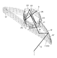
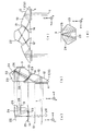
図1に実施例1の画像表示装置の光学系の主として右眼用部分の斜視図、図2に実施例1の光学系の軸上主光線2を示す透視斜視図、図3に異なる角度から見た実施例1の光学系の軸上主光線2を示す透視斜視図をそれぞれ示す。ただし、図1〜図3において面はメッシュで表現してある。また、図4に実施例1の画像表示装置の光学系の主として右眼用部分の光学面と光路を示す図を示す。ただし、(a)はZ軸正方向から見た右眼用光路の正面図、(b)はX軸負方向から見た右眼用光路の平面図、(c)はX軸負方向から見た第1の水平面内での両眼の光路を示す図、(d)はX軸負方向から見た第1の水平面と平行で第1の水平面より上(X軸の負側)の第2の水平面内での両眼の光路を示す図である。
【0054】
この光学系は、両眼装着型の頭部装着式画像表示装置として構成する場合の右眼用の光学系であり、左眼用の光学系は、X−Z面に平行で、両眼を結ぶ直線の中心を通る面に対して面対称に構成される。以下の実施例2も同様。なお、図1〜図4には、左眼用の接眼プリズム10’も図示してある。
【0055】
この実施例の観察光学系は、頭部装着式画像表示装置として構成する場合に観察者の右眼の瞳が位置すべき瞳1から出た逆光線追跡の軸上主光線(光軸)2は、保護ガラス4(図1〜図3においては図示略)を経て、接眼プリズム10の第11面11で屈折されて接眼プリズム10内に入り、第12面12で内部反射され、第11面11が兼ねる第13面13に臨界角を越える角度で入射して全反射され、第14面14で屈折されて接眼プリズム10から出て、光路振り分けプリズム20の第21面21で屈折されて光路振り分けプリズム20内に入り、第22面22で内部反射され、第23面23で内部反射され、第24面24で内部反射され、第25面25で内部反射され、第26面26で屈折されて光路振り分けプリズム20から出て、画像表示素子3に至る。
【0056】
ここで、接眼プリズム10の第11面11〜第14面14はY−Z面に対して面対称に構成されており、各面はこのY−Z面内で2次元的に偏心して構成されている。
【0057】
接眼プリズム10から出た軸上主光線は、第21面21から光路振り分けプリズム20内に入射し、接眼プリズム10の偏心面(Y−Z面:第1の水平面H1(図4(c)の面))内を進み、その第22面22の反射面で接眼プリズム10の偏心面(Y−Z面)と垂直な面H3(X軸と平行な面)内に反射され、その反射光は第23面23の反射面で反射され、その反射光は第1の水平面H1と平行でそれより上(X軸の負側)の第2の水平面H2(図4(d)の面)内を進み、第24面24の反射面で反射されて第2の水平面H2内を進み、第25面25の反射面で反射されてその第2の水平面H2内で第24面24に入射する軸上主光線と交差した後、第26面26で屈折されて画像表示素子3の中心に、画像表示素子3の中心を通る法線に対して−19.57°(図6(b))の角度をなして入射する。光路振り分けプリズム20の第21面21の上方(X軸の負側)に第23面23が、第22面22の上方(X軸の負側)に第24面24が配置されており、画像表示素子3の表示面はX−Y面に平行で、左右の瞳の間の中心を通る対称面にその中心が一致するように配置されている。
【0058】
そして接眼プリズム10、光路振り分けプリズム20共に正のパワーを有するように、それぞれの少なくとも1つの反射面は正パワーを有するように構成され、画像表示素子3の中間像を光路振り分けプリズム20の第21面21と第22面22の間に結像する。
【0059】
このように、観察光学系を3次元的に偏心させることで、光学系を自由な方向に折り畳むことができ、画像表示装置全体を小型化することができ、他の部材を考慮してデットスペースの少ない画像表示装置を提供することができる。さらには、デザインの自由度が大きくなる。また、光路振り分けプリズム20内の反射面を垂直方向に2段に配置するようにして、画角を広くした場合でも、両眼の反射面の有効径を確保できるようにしている。
【0060】
この実施例においては、光路振り分けプリズム20の第22面22の反射面を、接眼プリズム10の偏心面と垂直方向(本実施例ではX方向)に偏心させることで、第22面22で反射した像はX軸方向に傾く。その後、第23面23の反射面でX軸方向の像の傾きを0にするように反射面を構成することで、像の傾きが発生しないようにしている。このような構成にすることで、両眼の画像がY軸方向の傾きのみとなり、融像して観察することが可能となる。像面3上にてX方向とY方向の両方に対して像の傾きが発生した場合、画像表示素子3上に射影される像は軸上主光線を軸として左右逆方向に回転した像となり、両眼の画像を融像することができなくなる。また、第23面23から第25面25までの反射面は、第21面21及び第22面22の上下方向(X軸方向)に配置することができるため、光路振り分けブリズム20内の各反射面の干渉を防ぐことができる。さらに、上記X軸方向は、瞳の長手方向とは垂直方向になるため、大きく偏心させずに各面を構成することができ、X軸に非対称な偏心収差の発生量を小さく抑えることができる。
【0061】
実施例1の構成における瞳座標に対する像の傾きを図示したものが図5、図6(a)〜(b)である(図5は図4(c)に対応、図6(a)は図4(a)に対応、図6(b)は図4(d)に対応)。これらの図中、X、Yは像の方向、Zは光の進行方向を示す。図5は、瞳1から第22面22までの両眼の光路図で、Y−Z平面内で偏心させている。図6(a)は、第24面24までの右眼用光路を示した図で、第21面21から第24面24までは、Y−Z面に垂直なX方向に偏心させている。図6(b)は、第23面23から像面(画像表示素子)3までの両眼の光路図で、Y−Z平面内で偏心させている。ただし、これらの図は、簡単のため、各面を平面の反射鏡としたときの像の方向を図示したものであり、結像作用は考慮していない。実際には、この実施例では中間像を形成しているため、途中の中間像の位置でX方向、Y方向が逆向きの像が形成されることとなる。
【0062】
本実施例においては、接眼プリズム10の偏心面を水平方向になるようにしているので、接眼プリズム10の縦方向の寸法が非常に小さくでき、小型軽量化が達成できる。また、光路振り分けプリズム20を3次元的に偏心させているため、より広い画角が達成できる。また、中間像を1回結像しているため、光路振り分けプリズム20の高さは、接眼プリズム10の高さよりも小さく、光路振り分けプリズム20を3次元的に偏心させても、装置の小型化が達成できる。また、中間像から画像表示素子3までの物像間距離が長くとれ、光路振り分けプリズム20の各面のパワーを弱く設定することができる。そのため、画像表示素子3の表示面上で良好な性能を確保することができる。また、この実施例においては、画像表示素子3を光路振り分けプリズム20に対して観察者と反対側に配置できるため、画像表示素子3及びそのためのバックライトを配置するスペース上の問題は発生し難い。
【0063】
さらに、この実施例においては、光路振り分けプリズム20に4つの反射面22〜25があり、その中の2つの反射面22、23はX軸方向に偏心させ、2つの反射面24、25はY軸方向に偏心させているため、3次元的に光路をとっても良好な偏心収差補正が可能となる。
【0064】
なお、接眼プリズム10と瞳1の間にある平行平板4は保護ガラス用として挿入したものである。この保護ガラス4に正のパワーを付けることで、より広い画角がとれることは言うまでもない。
【0065】
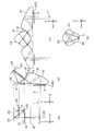
実施例2
図7に実施例2の図4と同様の図を示す。この実施例の観察光学系は、頭部装着式画像表示装置として構成する場合に観察者の右眼の瞳が位置すべき瞳1から出た逆光線追跡の軸上主光線(光軸)2は、保護ガラス4を経て、接眼プリズム10の第11面11で屈折されて接眼プリズム10内に入り、第12面12で内部反射され、第11面11が兼ねる第13面13に臨界角を越える角度で入射して全反射され、第14面14で屈折されて接眼プリズム10から出て、光路振り分けプリズム20の第21面21で屈折されて光路振り分けプリズム20内に入り、第22面22で内部反射され、第23面23で内部反射され、第24面24で内部反射され、第25面25で屈折されて光路振り分けプリズム20から出て、画像表示素子3に至る。
【0066】
ここで、接眼プリズム10の第11面11〜第14面14はY−Z面に対して面対称に構成されており、各面はこのY−Z面内で2次元的に偏心して構成されている。
【0067】
接眼プリズム10から出た軸上主光線は、第21面21から光路振り分けプリズム20内に入射し、接眼プリズム10の偏心面(Y−Z面:第1の水平面H1(図4(c)の面))内を進み、その第22面22の反射面で接眼プリズム10の偏心面(Y−Z面)と垂直な面H3(X軸と平行な面)内に反射され、その反射光は第23面23の反射面で反射され、その反射光は第1の水平面H1と平行でそれより上(X軸の負側)の第2の水平面H2(図4(d)の面)内を進み、第24面24の反射面で反射されて第2の水平面H2内を進み、第25面25で屈折されて画像表示素子3の中心に、画像表示素子3の中心を通る法線に対して−31.32°の角度をなして入射する。光路振り分けプリズム20の第21面21の上方(X軸の負側)に第23面23が、第22面22の上方(X軸の負側)に第24面24が配置されており、画像表示素子3の表示面はX−Y面に平行で、左右の瞳の間の中心を通る対称面にその中心が一致するように配置されている。
【0068】
そして接眼プリズム10、光路振り分けプリズム20共に正のパワーを有するように、それぞれの少なくとも1つの反射面は正パワーを有するように構成され、画像表示素子3の中間像を光路振り分けプリズム20の第21面21と第22面22の間に結像する。
【0069】
このように、観察光学系を3次元的に偏心させることで、光学系を自由な方向に折り畳むことができ、画像表示装置全体を小型化することができ、他の部材を考慮してデットスペースの少ない画像表示装置を提供することができる。さらには、デザインの自由度が大きくなる。また、光路振り分けプリズム20内の反射面を垂直方向に2段に配置するようにして、画角を広くした場合でも、両眼の反射面の有効径を確保できるようにしている。
【0070】
実施例2においても、実施例1と同様、光路振り分けプリズム20の第22面22の反射面を、接眼プリズム10の偏心面と垂直方向(本実施例ではX方向)に偏心させることで、第22面22で反射した像はX軸方向に傾く。その後、第23面23の反射面でX軸方向の像の傾きを0にするように反射面を構成することで、像の傾きが発生しないようにしている。このような構成にすることで、両眼の画像がY軸方向の傾きのみとなり、融像して観察することが可能となる。像面3上にてX方向とY方向の両方に対して像の傾きが発生した場合、画像表示素子3上に射影される像は軸上主光線を軸として左右逆方向に回転した像となり、両眼の画像を融像することができなくなる。また、第23面23から第24面24までの反射面は、第21面21及び第22面22の上下方向(X軸方向)に配置することができるため、光路振り分けブリズム20内の各反射面の干渉を防ぐことができる。さらに、上記X軸方向は、瞳の長手方向とは垂直方向になるため、大きく偏心させずに各面を構成することができ、X軸に非対称な偏心収差の発生量を小さく抑えることができる。
【0071】
本実施例においては、接眼プリズム10の偏心面を水平方向になるようにしているので、接眼プリズム10の縦方向の寸法が非常に小さくでき、小型軽量化が達成できる。また、光路振り分けプリズム20を3次元的に偏心させているため、より広い画角が達成できる。また、中間像を1回結像しているため、光路振り分けプリズム20の高さは、接眼プリズム10の高さよりも小さく、光路振り分けプリズム20を3次元的に偏心させても、装置の小型化が達成できる。また、中間像から画像表示素子3までの物像間距離が長くとれ、光路振り分けプリズム20の各面のパワーを弱く設定することができる。そのため、画像表示素子3の表示面上で良好な性能を確保することができる。また、この実施例においては、画像表示素子3を光路振り分けプリズム20の観察者側に配置しているが、画像表示素子3が眼の位置に対して少し上側に存在するため(光路振り分けプリズム20が2段構成の3次元構成にしてあるため) 、画像表示素子3と観察者の鼻との干渉は起こり難い。
【0072】
さらに、この実施例においては、光路振り分けプリズム20に3つの反射面22〜24があり、その中の2つの反射面22、23はX軸方向に偏心させ、1つの反射面24はY軸方向に偏心させているため、3次元的に光路をとっても良好な偏心収差補正が可能となる。
【0073】
なお、接眼プリズム10と瞳1の間にある平行平板4は保護ガラス用として挿入したものである。この保護ガラス4に正のパワーを付けることで、より広い画角がとれることは言うまでもない。
【0074】
次に、上記実施例1〜2の構成パラメータを示す。各実施例の構成パラメータにおいては、逆光線追跡で、軸上主光線2を、光学系の射出瞳1の中心を垂直に通り、画像表示素子3中心に至る光線で定義する。そして、逆光線追跡において、瞳1の中心を偏心光学系の偏心光学面の原点として、軸上主光線2に沿う方向をZ軸方向とし、瞳1から第11面11に向かう方向をZ軸正方向とし、接眼プリズム10内で光軸が折り曲げられる平面をY−Z平面とし、原点を通りY−Z平面に直交し、垂直方向の上から下へ向かう方向をX軸正方向とし、X軸、Z軸と右手直交座標系を構成する軸をY軸とする。この座標系は、図4、図7に図示してある座標系と同じである。
【0075】
偏心面については、光学系の原点の中心からその面の面頂位置の偏心量(X軸方向、Y軸方向、Z軸方向をそれぞれX,Y,Z)と、その面の中心軸(自由曲面については、前記(a)式のZ軸、非球面については、後記の(d)式のZ軸)のX軸、Y軸、Z軸それぞれを中心とする傾き角(それぞれα,β,γ(°))とが与えられている。その場合、αとβの正はそれぞれの軸の正方向に対して反時計回りを、γの正はZ軸の正方向に対して時計回りを意味する。なお、面の中心軸のα,β,γの回転のさせ方は、面の中心軸とそのXYZ直交座標系を、まずX軸の回りで反時計回りにα回転させ、次に、その回転した面の中心軸を新たな座標系のY軸の回りで反時計回りにβ回転させると共に1度回転した座標系もY軸の回りで反時計回りにβ回転させ、次いで、その2度回転した面の中心軸を新たな座標系の新たな座標系のZ軸の回りで時計回りにγ回転させるものである。
【0076】
また、各実施例の光学系を構成する光学作用面の中、特定の面とそれに続く面が共軸光学系を構成する場合には面間隔が与えられており、その他、媒質の屈折率、アッベ数が慣用法に従って与えられている。
【0077】
また、本発明で用いられる自由曲面の面の形状は前記(a)式により定義し、その定義式のZ軸が自由曲面の軸となる。
【0078】
また、非球面は、以下の定義式で与えられる回転対称非球面である。
【0079】
【0080】
なお、データの記載されていない自由曲面、非球面に関する項は0である。屈折率については、d線(波長587.56nm)に対するものを表記してある。
長さの単位はmmである。
【0081】
なお、実施例1〜2は、観察光学系とした場合に、観察画角は、水平半画角12.5°、垂直半画角9.4°、画像表示素子3の大きさは10.2×7.6mmであり、瞳径4mmある。
【0082】
なお、以下の構成パラメータの表中の“FFS”は自由曲面、“ASS”は非球面、“RE”は反射面をそれぞれ示す。
【0083】
ところで、本発明の画像表示装置においては、単一の画像表示素子3から射出されたある程度広がりのある射出角度の表示光束を左右の光路に分離して光路振り分けプリズム20の入射面26(実施例1)又は25(実施例2)に入射させ、左右の接眼光学系10、10’を通して両眼で観察可能にするものであるが、図8(a)に示すように、そのための左右共通の画像表示素子3としては、白色バックライト32で均一に照明され、左右の光路の光軸間のなす角度φより大きな射出角度で表示光束を射出させる液晶表示素子31からなる画像表示素子3が用いられる。また、表示の射出角度が大きなEL素子のような自己発光型素子を画像表示素子3として用いることもできる。
【0086】
また、表示の射出角度が小さな画像表示素子33を画像表示素子3として用いる場合には、図8(b)に示すように、各画素34から放射される表示の射出角度を垂直方向でなく左右の光路方向に射出角度を増やす振り分け光増強部材として、例えば図示のような断面の光束振り分けマイクロプリズム35を各画素34に対応して配置することが望ましい。その代わりに、0次透過光の強度を弱め、±1次回折光を強める構成の透過型回折格子を画像表示素子3の表示面に近接して配置してもよい。
【0087】
ところで、光路振り分けプリズム20の入射面26(実施例1)又は25(実施例1)に対して光路上最も近い位置に配置された左右の反射面25(実施例1)又は24(実施例2)の境界部分29に画像表示素子3から射出された表示光束が当たると、そこで反射されてゴースト光となる恐れがある。そこで、図8(c)に示すように、その境界部分29近傍にこのような反射を防止する反射防止部材36として黒色塗料を塗布するか拡散処理等をして、画像表示素子3から射出された表示光束37中の境界部分29に入射する破線で示した光束部分を吸収等させることが望ましい。なお、表示光束37中の実線で示した光束部分が左右の光路に導かれ、有効に表示に使用される光束を表す。
【0088】
さて、以上に説明したような観察光学系を支持することにより、両眼装着用の画像表示装置に構成することができ、両眼で観察できる据え付け型又はポータブル型の画像表示装置として構成することができる。
【0089】
その様子を図9に示す。図中、131は表示装置本体部を示し、観察者の顔面の両眼の前方に保持されるよう支持部材が頭部を介して固定している。その支持部材としては、一端を表示装置本体部131に接合し、観察者のこめかみから耳の上部にかけて延在する左右の前フレーム132と、前フレーム132の他端に接合され、観察者の側頭部を渡るように延在する左右の後フレーム133と、左右の後フレーム133の他端に挟まれるように自らの両端を一方づつ接合し、観察者の頭頂部を支持する頭頂フレーム134とから構成されている。
【0090】
また、前フレーム132における上記の後フレーム133との接合近傍には、弾性体からなり例えば金属板バネ等で構成されたリヤプレート135が接合されている。このリヤプレート135は、上記支持部材の一翼を担うリヤカバー136が観察者の後頭部から首のつけねにかかる部分で耳の後方に位置して支持可能となるように接合されている。リヤプレート135又はリヤカバー136内にの観察者の耳に対応する位置にスピーカー139が取り付けられている。
【0091】
映像・音声信号等を外部から送信するためのケーブル141が表示装置本体部131から、頭頂フレーム134、後フレーム133、前フレーム132、リヤプレート135の内部を介してリヤプレート135あるいはリヤカバー136の後端部より外部に突出している。そして、このケーブル141はビデオ再生装置140に接続されている。なお、図中、140aはビデオ再生装置140のスイッチやボリュウム調整部である。
【0092】
なお、ケーブル141は先端をジャックして、既存のビデオデッキ等に取り付け可能としてもよい。さらに、TV電波受信用チューナーに接続してTV鑑賞用としてもよいし、コンピュータに接続してコンピュータグラフィックスの映像や、コンピュータからのメッセージ映像等を受信するようにしてもよい。また、邪魔なコードを排斥するために、アンテナを接続して外部からの信号を電波によって受信するようにしても構わない。
【0093】
また、本発明の画像表示装置の観察光学系は、瞳1側から被写体からの光を導入し、画像表示素子3の位置に撮像素子を配することにより結像光学系として用いることも可能である。図10に本発明の観察光学系の左右の片側のみの光学系を電子カメラ40の撮影部の撮影用対物光学系42に組み込んだ構成の概念図を示す。もちろん、本発明の観察光学系の左右の両方の光学系を用いてもよい(入射瞳が2個の光学系になる。)。この例の場合は、撮影用光路41上に配置された撮影用対物光学系42は、実施例1と同様の光学系を光路を逆にして用いており、瞳1の位置に絞り1’を配置している。この撮影用対物光学系42により形成された物体像は、ローパスフィルター、赤外カットフィルター等のフィルター44を介してCCD45の撮像面46上に形成される。このCCD45で受光された物体像は、処理手段51を介し、液晶表示素子(LCD)52上に電子像として表示される。また、この処理手段51は、CCD45で撮影された物体像を電子情報として記録する記録手段54の制御も行う。LCD52に表示された画像は、接眼プリズム10と同様な偏心プリズムからなる接眼光学系53を介して観察者眼球Eに導かれる。この接眼光学系53としては、本発明による片側の接眼プリズム10と光路振り分けプリズム20からなる3次元偏心光学系を用いてもよい。なお、この撮影用対物光学系42は他のレンズ(正レンズ、負レンズ)をプリズム10の物体側あるいはプリズム20の像側にその構成要素として含んでいてもよい。
【0094】
このように構成されたカメラ40は、撮影用対物光学系42を少ない光学部材で構成でき、装置全体を小型化することができ、低価格で、他の部材を考慮してデットスペースの少ないカメラとすることができると共に、デザインの自由度が大きなものとなる。
【0095】
なお、本例では、撮影用対物光学系42のカバー部材43はとして、平行平面板を配置しているが、パワーを持ったレンズを用いてもよい。
【0096】
また、本発明の観察光学系の左右の片側のみの光学系は、画像表示素子3の位置に投影用の像面を配置し、瞳1の前方にスクリーンを配置することにより投影光学系としても用いることができる。もちろん、この場合も、本発明の観察光学系の左右の両方の光学系を用いてもよい(射出瞳が2個の光学系になる。)。図11に、パソコン90と液晶プロジェクタ91とを組み合わせたプレゼンテーションシステムの投影光学系96に本発明による偏心プリズム光学系を用いた構成の概念図を示す。この例の場合は、投影光学系96に実施例1と同様の光学系を用いている。同図において、パソコン90上で作成された画像・原稿データは、モニタ出力から分岐して液晶プロジェクタ91の処理制御部98に出力される。液晶プロジェクタ91の処理制御部98では、この入力されたデータが処理され、液晶パネル(LCP)93に出力される。液晶パネル93では、この入力画像データに応じた画像が表示される。そして、光源92からの光は、液晶パネル93に表示した画像の階調によってその透過量が決定された後、液晶パネル93直前に配置したフィールドレンズ95と本発明の光学系を構成するプリズム20、10と正レンズのカバーレンズ94とからなる投影光学系96を介してスクリーン97に投影される。
【0097】
このように構成されたプロジェクタは、少ない光学部材で構成でき、低コスト化が実現できると共に、小型化が可能である。
【0098】
以上の本発明の3次元偏心光路を備えた画像表示装置は、例えば次のように構成することができる。
【0099】
〔1〕 観察画像を画像表示部に形成する画像表示素子と、前記画像表示素子が形成した画像を観察者眼球位置に相当する瞳に導く観察光学系とを含んだ画像表示装置において、
前記画像表示素子が、複数の画素を単板上に並設させた1枚の画像表示素子を有して構成され、
前記1枚の画像表示素子の少なくとも中央部分に位置する各画素が、観察者の左右の眼球に光束を導けるような射出角度で画像光束を放射するように構成され、
前記観察光学系が、少なくとも、観察者の左眼に光束を導く左接眼部と、観察者の右眼に光束を導く右接眼部と、前記画像表示素子から前記射出角度を持って放射された画像光束を前記左右の接眼部に導く3次元光路振り分け部とを含み、
前記左接眼部が、少なくとも2面以上の反射面を有し、その中の少なくとも1つの反射面が偏心収差補正機能を有した回転非対称な曲面反射面にて構成され、
前記右接眼部が、少なくとも2面以上の反射面を有し、その中の少なくとも1つの反射面が偏心収差補正機能を有した回転非対称な曲面反射面にて構成され、
前記左接眼部の有する前記2面以上の反射面にて形成される軸上主光線の偏心光路面(Y−Z面)と、前記右接眼部の有する前記2面以上の反射面にて形成される軸上主光線の偏心光路面(Y−Z面)とが、同一平面(Y−Z面)に形成されるように、前記左右接眼部が構成され、
前記3次元光路振り分け部は、左右対称な光路を形成できるように、左右対称に光学面が配置され、かつ、前記光学面の中、少なくとも左右2組の反射面が、前記左右の接眼部によって形成される偏心光路面(Y−Z面)に対して垂直な方向(X方向)の成分をも含めた3次元偏心方向に左右各々の光束の軸上主光線を反射させるように構成されていることを特徴とする3次元偏心光路を備えた画像表示装置。
【0100】
〔2〕 上記1において、
前記3次元光路振り分け部が、偏心収差補正機能を有した回転非対称な曲面形状の反射面を少なくとも1組備えていることを特徴とする3次元偏心光路を備えた画像表示装置。
【0101】
〔3〕 上記2において、
前記の少なくとも1組の偏心収差補正機能を有した回転非対称な曲面形状の反射面は、前記の3次元偏心方向に左右各々の光束の軸上主光線を反射させる少なくとも左右2組の反射面の中の1組に配置されていることを特徴とする3次元偏心光路を備えた画像表示装置。
【0102】
〔4〕 上記2において、
前記の少なくとも1組の偏心収差補正機能を有した回転非対称な曲面形状の反射面は、対称面を1面のみ有する自由曲面にて形成され、
前記の少なくとも1組の自由曲面の各々の唯一の対称面が同一平面内に一致するように構成されていることを特徴とする3次元偏心光路を備えた画像表示装置。
【0103】
〔5〕 上記1〜4の何れか1項において、
前記観察光学系が、プリズム部材にて形成され、前記反射面の何れもが前記プリズム部材の表面に形成された裏面反射面にて構成されていることを特徴とする3次元偏心光路を備えた画像表示装置。
【0104】
〔6〕 上記5において、
前記観察光学系は、前記3次元光路振り分け部を構成する3次元光路振り分けプリズムと、前記3次元光路振り分けプリズムと空気間隔を挟んで分離され、前記左接眼部を構成する左接眼プリズムと前記右接眼部を構成する右接眼プリズムとを含んで構成されていることを特徴とする3次元偏心光路を備えた画像表示装置。
【0105】
〔7〕 上記6において、
前記光路振り分けプリズムが、少なくとも前記画像表示素子に対向し左眼用光路を形成する画像光束と右眼用光路を形成する画像光束の両方の光束をプリズム内に入射させる入射面と、前記左眼用光路の光束を前記プリズム外に射出する左側射出面と、前記入射面と前記左側射出面との間の光路上に配置されかつ前記左眼用光路の光束を前記プリズム内で反射する少なくとも3面以上の左側反射面と、前記右眼用光路の光束を前記プリズム外に射出する右側射出面と、前記入射面と前記右側射出面との間の光路上に配置されかつ前記右眼用光路の光束を前記プリズム内で反射する少なくとも3面以上の右側反射面とを含んで構成され、
前記少なくとも3面以上の左側反射面の中の前記入射面に対して前記左眼用光路上最も近い位置に配置された反射面に入射する軸上主光線とそこから反射する軸上主光線とを含む左第1平面と、前記少なくとも3面以上の右側反射面の中の前記入射面に対して前記右眼用光路上最も近い位置に配置された反射面に入射する軸上主光線とそこから反射する軸上主光線とを含む右第1平面とが、同一の第1平面内に一致するように構成されていることを特徴とする3次元偏心光路を備えた画像表示装置。
【0106】
〔8〕 上記7において、
前記第1平面が、前記左接眼部の前記偏心光路面と前記右接眼部の前記偏心光路面とを含む同一平面である第2平面に対して、異なる平面からなり、かつ、前記第1平面と前記第2平面とが平行な位置関係を形成するように、前記観察光学系が構成されていることを特徴とする3次元偏心光路を備えた画像表示装置。
【0107】
〔9〕 上記8において、
前記少なくとも3面以上の左側反射面の中、2つの左側反射面が、前記第1平面に対して垂直方向に隣接配置され、かつ、前記少なくとも3面以上の右側反射面の中、2つの右側反射面が、前記第1平面に対して垂直方向に隣接配置されるように前記光路振り分けプリズムが構成されていることを特徴とする3次元偏心光路を備えた画像表示装置。
【0108】
〔10〕 上記9において、
前記第2平面に対して垂直な方向の成分をも含めた3次元偏心方向に左右各々の光束の軸上主光線を反射させる少なくとも左右2組の反射面の中、1組の左側反射面と右側反射面について、前記左側反射面と前記左側射出面とが第1平面に対して垂直方向に隣接配置され、かつ、前記右側反射面と前記右側射出面とが前記第1平面に対して垂直方向に隣接配置されていることを特徴とする3次元偏心光路を備えた画像表示装置。
【0109】
〔11〕 上記7〜10の何れか1項において、
前記入射面に対して前記左眼用光路上最も近い位置に配置された反射面と、前記入射面に対して前記右眼用光路上最も近い位置に配置された反射面とが共に、前記画像表示素子と前記入射面の双方に対して対向するように隣接配置されていることを特徴とする3次元偏心光路を備えた画像表示装置。
【0110】
〔12〕 上記11において、
前記光路振り分けプリズムが、前記入射面に対して光路上最も近い位置に配置された左右の反射面の境界部分を含む領域に対して、前記画像表示素子の中心領域から垂直に放射された光線がゴースト光として反射しないように反射防止部材を設けたことを特徴とする3次元偏心光路を備えた画像表示装置。
【0111】
〔13〕 上記1〜12の何れか1項において、
前記画像表示素子と前記3次元光路振り分け部との間に、前記1枚の画像表示素子の少なくとも中央部分に位置する各画素から放射される所定の射出角度を持った画像光束の光強度を前記各画素面の垂直方向に放射される光束強度より強くするような振り分け光増強部材を配置したことを特徴とする3次元偏心光路を備えた画像表示装置。
【0112】
〔14〕 上記7〜13の何れか1項において、
前記光路振り分けプリズムは、前記少なくとも3面以上の左側反射面によって前記画像表示素子から放射された前記左眼用光路の軸上主光線を前記プリズム内で回転交差させると共に、前記少なくとも3面以上の右側反射面によって前記画像表示素子から放射された前記右眼用光路の軸上主光線を前記プリズム内で回転交差させ、かつ、前記左側反射面による回転方向と前記右側反射面による回転方向とが逆回転となるように構成されていることを特徴とする3次元偏心光路を備えた画像表示装置。
【0113】
〔15〕 上記14において、
前記光路振り分けプリズムが、前記左側反射面によって形成された前記左眼用光路の軸上主光線の回転交差平面が前記左第1平面と同一平面内に形成され、かつ、前記右側反射面によって形成された前記右眼用光路の軸上主光線の回転交差平面が前記右第1平面内に形成されるように構成されていることを特徴とする3次元偏心光路を備えた画像表示装置。
【0114】
〔16〕 上記1〜15の何れか1項において、
前記3次元光路振り分け部に含まれる左右対称な複数組の反射面が、前記画像表示素子側から順に、左右1組の第1反射面と、左右1組の第2反射面と、左右1組の第3反射面と、左右1組の第4反射面とから構成され、
少なくとも前記第1反射面が、光束にパワーを与える曲面反射面形状にて構成され、かつ、偏心収差補正機能を有した回転非対称形状にて構成されていることを特徴とする3次元偏心光路を備えた画像表示装置。
【0115】
〔17〕 上記1〜16の何れか1項において、
前記3次元光路振り分け部に含まれる左右対称な複数組の反射面が、前記画像表示素子側から順に、左右1組の第1反射面と、左右1組の第2反射面と、左右1組の第3反射面と、左右1組の第4反射面とから構成され、
少なくとも前記第2反射面が、光束にパワーを与える曲面反射面形状にて構成され、かつ、偏心収差補正機能を有した回転非対称形状にて構成されていることを特徴とする3次元偏心光路を備えた画像表示装置。
【0116】
〔18〕 上記1〜17の何れか1項において、
前記3次元光路振り分け部に含まれる左右対称な複数組の反射面が、前記画像表示素子側から順に、左右1組の第1反射面と、左右1組の第2反射面と、左右1組の第3反射面と、左右1組の第4反射面とから構成され、
少なくとも前記第3反射面が、光束にパワーを与える曲面反射面形状にて構成され、かつ、偏心収差補正機能を有した回転非対称形状にて構成されていることを特徴とする3次元偏心光路を備えた画像表示装置。
【0117】
〔19〕 上記1〜18の何れか1項において、
前記3次元光路振り分け部に含まれる左右対称な複数組の反射面が、前記画像表示素子側から順に、左右1組の第1反射面と、左右1組の第2反射面と、左右1組の第3反射面と、左右1組の第4反射面とから構成され、
少なくとも前記第4反射面が、光束にパワーを与える曲面反射面形状にて構成され、かつ、偏心収差補正機能を有した回転非対称形状にて構成されていることを特徴とする3次元偏心光路を備えた画像表示装置。
【0118】
〔20〕 上記16〜19の何れか1項において、
前記3次元光路振り分け部の左眼用光路の第3反射面に入射する軸上主光線とそこから反射する軸上主光線と左眼用光路の第4反射面で反射する軸上主光線とが同一の左第2平面内に含まれ、右眼用光路の第3反射面に入射する軸上主光線とそこから反射する軸上主光線と右眼用光路の第4反射面で反射する軸上主光線とが同一の右第2平面内に含まれ、前記左第2平面と前記右第2平面は、前記第1平面に垂直に設定されていることを特徴とする3次元偏心光路を備えた画像表示装置。
【0119】
〔21〕 上記1〜20の何れか1項において、
前記3次元光路振り分け部に含まれる回転非対称形状の曲面反射面が、対称面を1面のみ備えた自由曲面形状にて構成されていることを特徴とする3次元偏心光路を備えた画像表示装置。
【0120】
〔22〕 上記6〜21の何れか1項において、
前記左接眼プリズムと前記右接眼プリズムが共に、前記3次元光路振り分けプリズム側から順に、入射面と第1反射面と第2反射面と射出面とからなり、前記第1反射面と前記射出面は同一面からなり、前記第1反射面はその面での全反射による反射面であることを特徴とする3次元偏心光路を備えた画像表示装置。
【0121】
【発明の効果】
以上の説明から明らかに、本発明によると、画像表示素子が1枚で両眼視できるため、コストが非常に安くなる。また、両眼に画像を振り分ける光路振り分けプリズムに自由曲面を用いているため、良好に収差補正ができる。また、ハーフミラーを使用していないため、明るい画像が観察できる。さらに、光路振り分けプリズムを3次元的に偏心させているため、画像表示素子が1枚で両眼視できる非常に広い画角の表示装置を提供することができる。さらに、接眼プリズムの偏心面を水平にしているため、幅の非常に小さい画像表示装置が提供でき、広いシーアラウンドが可能となる。
【図面の簡単な説明】
【図1】本発明の実施例1の画像表示装置の光学系の主として右眼用部分の斜視図である。
【図2】実施例1の光学系の軸上主光線を示す透視斜視図である。
【図3】異なる角度から見た実施例1の光学系の軸上主光線を示す透視斜視図である。
【図4】実施例1の画像表示装置の光学系の主として右眼用部分の光学面と光路を示す図である。
【図5】実施例1の構成における瞳座標に対する像の傾きを示した図である。
【図6】実施例1の構成における瞳座標に対する像の傾きを示した図である。
【図7】実施例2の画像表示装置の光学系の主として右眼用部分の光学面と光路を示す図である。
【図8】本発明において使用可能な画像表示素子、そのための振り分け光増強部材、反射防止部材を説明するための図である。
【図9】本発明の画像表示装置を両眼に装着する構成にした場合の様子を示す図である。
【図10】本発明の光学系を電子カメラの撮影部の撮影用対物光学系に組み込んだ構成の概念図である。
【図11】本発明による光学系をプレゼンテーションシステムの投影光学系に用いた構成の概念図である。
【符号の説明】
E…観察者の眼
1…瞳
1’…絞り
2…軸上主光線(光軸)
3…画像表示素子
4…保護ガラス
10、10’…接眼プリズム
11…第11面
12…第12面
13…第13面
14…第14面
20…光路振り分けプリズム
21…第21面
22…第22面
23…第23面
24…第24面
25…第25面
26…第26面
29…境界部分
31…液晶表示素子
32…白色バックライト
33…画像表示素子
34…画素
35…光束振り分けマイクロプリズム
36…反射防止部材
37…表示光束
40…電子カメラ
41…撮影用光路
42…撮影用対物光学系
43…カバー部材
44…フィルター
45…CCD
46…撮像面
51…処理手段
52…液晶表示素子(LCD)
53…接眼光学系
54…記録手段
90…パソコン
91…液晶プロジェクタ
92…光源
93…液晶パネル(LCP)
94…カバーレンズ
95…フィールドレンズ
96…投影光学系
97…スクリーン
98…処理制御部
131…表示装置本体部
132…前フレーム
133…後フレーム
134…頭頂フレーム
135…リヤプレート
136…リヤカバー
139…スピーカー
140…ビデオ再生装置
140a…ボリュウム調整部
141…ケーブル[0001]
BACKGROUND OF THE INVENTION
The present invention relates to an image display device having a three-dimensional eccentric optical path, and more particularly to a head- or face-mounted image display device that can be held on the head or face of an observer.
[0002]
[Prior art]
Conventionally, as a head-mounted image display device using a single image display element common to the left and right eyes, Japanese Patent Application Laid-Open No. 6-110013 guides display light from the image display element to the left and right eyes of an observer. In addition, it is divided by an isosceles triangular prism and mirror and bent. In this arrangement, correction of various aberrations is performed by a lens arranged in front of the pupil of the observer's eye, which makes correction difficult and increases the size of the apparatus.
[0003]
In Japanese Patent Laid-Open No. 7-287185, a plurality of mirrors are used and an image forming action is performed with a single convex lens. Therefore, assembly adjustment is very difficult, and appropriate performance cannot be achieved. Further, although the image display elements are arranged three-dimensionally, the left and right images are rotated in reverse.
[0004]
In JP-A-9-61748, display light from an image display element is divided using a half mirror and observed with both eyes. For this reason, the display light is divided into the left and right eyeballs, so the observation image intensity is weak and dark.
[0005]
Japanese Patent Laid-Open Nos. 9-181998 and 9-181999 use separate reflecting prism optical systems on the left and right sides, but have a problem that the angle of view is narrow.
[0006]
Furthermore, Japanese Patent Publication No. 10-504115 uses a half mirror to divide the display light, but has a very large number of parts and is very complicated to assemble.
[0007]
The present applicant has proposed a head-mounted image display device in which an optical path distribution optical system is arranged at the center and eyepiece prisms are arranged on the left and right sides thereof in Japanese Patent Application No. 2000-48750 and the like.
[0008]
[Problems to be solved by the invention]
The present invention has been made in view of such problems of the prior art, and its purpose is to guide a video from one image display element to both eyes without using a half mirror, and to observe brightly, It is another object of the present invention to provide an image display device such as a head-mounted image display device that facilitates correction of various aberrations by providing power to an optical path distribution optical system disposed in the center.
[0009]
Another object of the present invention is to further widen the angle of view of an image display device such as Japanese Patent Application No. 2000-48750 by the present applicant.
[0010]
[Means for Solving the Problems]
An image display device having a three-dimensional eccentric optical path of the present invention that achieves the above object corresponds to an image display element that forms an observation image on an image display unit, and an image formed by the image display element corresponds to an observer eyeball position. In an image display device including an observation optical system that leads to the pupil,
The image display element has a single image display element in which a plurality of pixels are arranged side by side on a single plate,
Each pixel located in at least the central portion of the one image display element is configured to emit an image light beam at an emission angle that can guide the light beam to the left and right eyeballs of an observer,
The observation optical system emits at least the left eyepiece that guides the light flux to the left eye of the observer, the right eyepiece that guides the light flux to the right eye of the observer, and the emission angle from the image display element. A three-dimensional optical path distribution unit that guides the imaged light flux to the left and right eyepieces,
The left eyepiece has at least two reflecting surfaces, and at least one of the reflecting surfaces is composed of a rotationally asymmetric curved reflecting surface having a decentration aberration correcting function,
The right eyepiece has at least two reflecting surfaces, and at least one of the reflecting surfaces is a rotationally asymmetric curved reflecting surface having a decentration correction function,
An eccentric optical path surface (YZ plane) of an axial principal ray formed by the two or more reflecting surfaces of the left eyepiece, and the two or more reflecting surfaces of the right eyepiece The left and right eyepieces are configured so that the decentered optical path surface (YZ plane) of the axial principal ray formed in the above is formed in substantially the same plane (YZ plane),
The three-dimensional optical path allocating unit has optical surfaces arranged symmetrically so as to form a bilaterally symmetric optical path, and at least two sets of right and left reflecting surfaces are the left and right eyepieces. The axial principal rays of the left and right light beams are reflected in the three-dimensional eccentric direction including the component in the direction (X direction) perpendicular to the eccentric optical path surface (YZ plane) formed by It is characterized by that.
[0011]
Hereinafter, the reason and effect | action which take the said structure in this invention are demonstrated.
[0012]
Usually, the distance between human eyes is said to be about 64 mm on average, and there are individual differences. Therefore, in the observation optical system for binocular observation, it is preferable to set the pupil of the optical system to be horizontally long in advance in order to absorb individual differences in eye widths with the observation optical system. That is, it is preferable to use an ellipse (or a rectangle or the like) that is long in the horizontal direction of the observer as the pupil of the observation optical system.
[0013]
At this time, if the longitudinal direction of the pupil and the eccentric direction of the eyepiece are made the same direction, the effective surface of each reflecting surface inevitably needs to ensure a long effective diameter. However, in the case of an optical system that is decentered only in the horizontal direction of the observer as in Japanese Patent Application No. 2000-48750, the optical system cannot be increased in the horizontal direction because of restrictions on the human eye width. Therefore, when the observation angle of view is widened, it becomes difficult to dispose the reflection surface of the optical path distribution unit between the eyepieces of both eyes.
[0014]
Therefore, in the observation optical system of the image display device of the present invention, the entire optical path in the optical path distribution unit is configured in a three-dimensional configuration, so that the reflection surface in the optical path distribution unit is arranged in the vertical direction, and the angle of view is set. Even in the case of widening, the effective diameter of the reflecting surfaces of both eyes can be secured.
[0015]
It should be noted that the left and right eyepieces and the three-dimensional optical path distribution units constituting the observation optical system may be configured by only reflecting mirrors, or the left and right eyepiece units and the three-dimensional optical path distribution units may be configured by eccentric prisms. Alternatively, the left and right eyepieces and the three-dimensional optical path distribution unit may be formed of an integral eccentric prism.
[0016]
The three-dimensional optical path distribution unit preferably includes at least one set of rotationally asymmetric curved surfaces having a decentration aberration correction function.
[0017]
In that case, the rotationally asymmetric curved reflecting surface having at least one set of decentration aberration correction function is at least of two sets of left and right reflecting surfaces that reflect the axial principal rays of the left and right light beams in the three-dimensional eccentric direction. It is desirable to arrange in one set.
[0018]
The rotationally asymmetric curved reflecting surface having at least one set of decentration aberration correction function is formed by a free curved surface having only one symmetrical surface, and each of the at least one set of free curved surfaces is the only one. It is desirable that the symmetry plane is configured to coincide with the same plane.
[0019]
Here, as a surface of a rotationally asymmetric curved surface shape, a free-form surface is typically used in the present invention. The free-form surface is defined by the following equation. The Z axis of this defining formula is the axis of the free-form surface.
[0020]
[0021]
In the spherical term,
c: vertex curvature
k: Conic constant (conical constant)
r = √ (X 2 + Y 2 )
It is.
[0022]
The free-form surface term is
[0023]
In general, the free-form surface does not have a symmetric surface in both the XZ plane and the YZ plane, but by setting all odd-order terms of X to 0, the plane of symmetry is parallel to the YZ plane. Is a free-form surface with only one. Further, by setting all odd-numbered terms of Y to 0, a free-form surface having only one symmetry plane parallel to the XZ plane is obtained.
[0024]
Further, another defining formula of the free-form surface which is a surface of the rotationally asymmetric curved surface can be defined by a Zernike polynomial. The shape of this surface is defined by the following formula (b). The Z axis of the defining formula (b) is the axis of the Zernike polynomial. The definition of the rotationally asymmetric surface is defined by polar coordinates of the height of the Z axis with respect to the XY plane, R is the distance from the Z axis in the XY plane, A is the azimuth around the Z axis, and the X axis It is expressed by the rotation angle measured from.
[0025]
[0026]
The above definition formula is shown for illustration of a rotationally asymmetric curved surface, and it goes without saying that the same effect can be obtained for any other definition formula.
[0027]
In addition, the following definition formula (c) is mention | raise | lifted as an example of the other definition formula of a free-form surface.
[0028]
Z = ΣΣC nm XY
As an example, when k = 7 (seventh order term) is considered, when expanded, it can be expressed by the following expression.
[0029]
[0030]
In the present invention, as described above, the observation optical system may be formed by a prism member, and any of the reflection surfaces may be configured by a back surface reflection surface formed on the surface of the prism member.
[0031]
In this case, the observation optical system is separated from the three-dimensional optical path distributing prism constituting the three-dimensional optical path distributing unit and the three-dimensional optical path distributing prism with a space between the left eyepiece prism constituting the left eyepiece unit and the right eyepiece. A right eyepiece prism that constitutes the eye portion may be included.
[0032]
The optical path distribution prism has at least an incident surface for allowing both the image light beam forming the left eye optical path and the image light beam forming the right eye optical path to enter the prism. The left exit surface that emits the light flux of the optical path out of the prism, and the left reflective surface that is disposed on the optical path between the entrance surface and the left exit surface and that reflects the light flux of the optical path for the left eye within the prism. And at least three surfaces arranged on the optical path between the right exit surface and the right exit surface for emitting the light flux of the right eye optical path out of the prism and reflecting the light flux of the right eye optical path within the prism. Including the above right reflective surface,
Including an axial principal ray incident on a reflecting surface disposed at a position closest to the incident surface in the left-eye optical path with respect to an incident surface among at least three left-side reflecting surfaces, and an axial principal ray reflected therefrom An axial principal ray incident on a reflecting surface disposed at a position closest to the right first optical path and an incident surface in the right reflecting surface of at least three or more of the first left plane and an axis reflecting from the axial principal ray It is desirable that the right first plane including the upper chief ray is configured to coincide with the same first plane.
[0033]
In this case, the first plane is different from the second plane which is substantially the same plane including the eccentric optical path surface of the left eyepiece and the eccentric optical path surface of the right eyepiece, and the first plane It is desirable that the observation optical system is configured so that the plane and the second plane form a parallel positional relationship.
[0034]
Here, the fact that the decentered optical path surfaces of the left and right eyepieces are substantially in the same plane means that a slight angle shift due to a manufacturing error or the like is included, and is ± 1 °.
[0035]
Of the at least three left reflective surfaces, the two left reflective surfaces are arranged adjacent to each other in the vertical direction with respect to the first plane, and the two right reflective surfaces are at least three right reflective surfaces. It is desirable that the optical path distribution prism is configured so that the surface is adjacent to the first plane in the vertical direction.
[0036]
Also, one set of left reflecting surfaces among at least two sets of reflecting surfaces that reflect the axial principal rays of the left and right light beams in the three-dimensional eccentric direction including the component perpendicular to the second plane. And the right reflecting surface, the left reflecting surface and the left emitting surface are arranged adjacent to each other in the vertical direction with respect to the first plane, and the right reflecting surface and the right emitting surface are arranged adjacent to each other in the direction perpendicular to the first plane. Can be.
[0037]
In addition, the reflection surface disposed at the closest position on the optical path for the left eye with respect to the incident surface and the reflective surface disposed at the position closest to the optical path for the right eye with respect to the incident surface are both image display elements and It is desirable that they are adjacently arranged so as to face both of the incident surfaces.
[0038]
In this case, the light beam emitted vertically from the central region of the image display element with respect to the region including the boundary portion of the left and right reflecting surfaces arranged at the closest position on the optical path with respect to the incident surface. It is desirable to provide an antireflection member so that the light is not reflected as ghost light.
[0039]
Further, between the image display element and the three-dimensional optical path distribution unit, the light intensity of the image light beam having a predetermined emission angle emitted from each pixel located at least in the central portion of the one image display element is set. It is desirable to arrange a sorting light enhancing member that is stronger than the intensity of light flux emitted in the direction perpendicular to the pixel surface.
[0040]
Further, the optical path distribution prism rotates and intersects the axial principal ray of the optical path for the left eye radiated from the image display element by at least three or more left reflecting surfaces, and at least three or more right reflecting surfaces. The axial principal ray of the optical path for the right eye radiated from the image display element is rotated and intersected in the prism, and the rotation direction by the left reflection surface and the rotation direction by the right reflection surface are reversed. It is desirable that
[0041]
In this case, the optical path distribution prism is formed by the right-side reflecting surface in which the rotation crossing plane of the axial principal ray of the optical path for the left eye formed by the left reflecting surface is formed in the same plane as the left first plane. It is desirable that the rotation intersecting plane of the axial principal ray of the right-eye optical path is formed in the right first plane.
[0042]
Further, a plurality of left and right symmetrical reflecting surfaces included in the three-dimensional optical path distribution unit are arranged in order from the image display element side, one set of left and right first reflecting surfaces, one set of left and right second reflecting surfaces, and one set of left and right sets. The third reflecting surface and a pair of left and right fourth reflecting surfaces,
It is desirable that at least the first reflecting surface is formed in a curved reflecting surface shape that gives power to the light beam and has a rotationally asymmetric shape having a decentration aberration correcting function.
[0043]
Further, a plurality of left and right symmetrical reflecting surfaces included in the three-dimensional optical path distribution unit are arranged in order from the image display element side, one set of left and right first reflecting surfaces, one set of left and right second reflecting surfaces, and one set of left and right sets. The third reflecting surface and a pair of left and right fourth reflecting surfaces,
It is desirable that at least the second reflecting surface is formed in a curved reflecting surface shape that gives power to the light beam, and has a rotationally asymmetric shape having a decentration aberration correcting function.
[0044]
Further, a plurality of left and right symmetrical reflecting surfaces included in the three-dimensional optical path distribution unit are arranged in order from the image display element side, one set of left and right first reflecting surfaces, one set of left and right second reflecting surfaces, and one set of left and right sets. The third reflecting surface and a pair of left and right fourth reflecting surfaces,
It is desirable that at least the third reflecting surface is formed in a curved reflecting surface shape that gives power to the light beam and has a rotationally asymmetric shape having a decentration aberration correction function.
[0045]
Further, a plurality of left and right symmetrical reflecting surfaces included in the three-dimensional optical path distribution unit are arranged in order from the image display element side, one set of left and right first reflecting surfaces, one set of left and right second reflecting surfaces, and one set of left and right sets. The third reflecting surface and a pair of left and right fourth reflecting surfaces,
It is desirable that at least the fourth reflecting surface is formed in a curved reflecting surface shape that gives power to the light beam, and has a rotationally asymmetric shape having a decentration aberration correcting function.
[0046]
In these cases, the axial principal ray incident on the third reflecting surface of the left-eye optical path of the three-dimensional optical path distribution unit, the axial principal ray reflected therefrom, and the axis reflected by the fourth reflecting surface of the left-eye optical path. An axial chief ray incident on the third reflecting surface of the right-eye optical path, an axial chief ray reflected therefrom, and the fourth reflecting surface of the right-eye optical path are included in the same second left plane. It is desirable that the axial chief ray reflected at 1 is included in the same right second plane, and the left second plane and the right second plane are set perpendicular to the first plane.
[0047]
In addition, it is desirable that the rotationally asymmetric curved reflecting surface included in the three-dimensional optical path distributing unit is configured as a free curved surface having only one symmetric surface.
[0048]
Further, both the left eyepiece prism and the right eyepiece prism are composed of an incident surface, a first reflecting surface, a second reflecting surface, and an exit surface in order from the three-dimensional optical path distribution prism side, and the first reflecting surface and the exit surface are the same surface. The first reflecting surface can be a reflecting surface by total reflection on the surface.
[0049]
DETAILED DESCRIPTION OF THE INVENTION
Hereinafter, an image display device having a three-dimensional eccentric optical path of the present invention will be described based on examples.
[0050]
In the following examples, coordinates are set such that the observer's visual axis direction (front direction) is the Z axis, the horizontal direction is the Y axis, and the vertical direction is the X axis.
[0051]
In the numerical data of each example described later, the observation optical system for the right eye is shown, and it is shown by the data of back ray tracing from the
[0052]
In Examples 1 and 2 described below, the
[0053]
Example 1
FIG. 1 is a perspective view mainly showing a right-eye portion of the optical system of the image display apparatus of
[0054]
This optical system is an optical system for the right eye when configured as a binocular head-mounted image display device. The optical system for the left eye is parallel to the XZ plane and The plane is symmetrical with respect to a plane passing through the center of the connecting straight line. The same applies to Example 2 below. 1 to 4 also show an
[0055]
When the observation optical system of this embodiment is configured as a head-mounted image display device, an axial principal ray (optical axis) 2 for tracing back rays from the
[0056]
Here, the
[0057]
The axial principal ray emitted from the
[0058]
The
[0059]
Thus, by decentering the observation optical system three-dimensionally, the optical system can be folded in a free direction, the entire image display device can be miniaturized, and dead space in consideration of other members. It is possible to provide an image display device with less image quality. Furthermore, the degree of freedom of design is increased. Further, the reflecting surfaces in the optical
[0060]
In this embodiment, the reflection surface of the
[0061]
FIGS. 5 and 6A to 6B illustrate the inclination of the image with respect to the pupil coordinates in the configuration of the first embodiment (FIG. 5 corresponds to FIG. 4C, and FIG. 4 (a), FIG. 6 (b) corresponds to FIG. 4 (d)). In these drawings, X and Y indicate the image direction, and Z indicates the light traveling direction. FIG. 5 is an optical path diagram of both eyes from the
[0062]
In the present embodiment, since the eccentric surface of the
[0063]
Further, in this embodiment, the optical
[0064]
The parallel plate 4 between the
[0065]
Example 2
FIG. 7 is a view similar to FIG. 4 of the second embodiment. When the observation optical system of this embodiment is configured as a head-mounted image display device, an axial principal ray (optical axis) 2 for tracing back rays from the
[0066]
Here, the
[0067]
The axial principal ray emitted from the
[0068]
The
[0069]
Thus, by decentering the observation optical system three-dimensionally, the optical system can be folded in a free direction, the entire image display device can be miniaturized, and dead space in consideration of other members. It is possible to provide an image display device with less image quality. Furthermore, the degree of freedom of design is increased. Further, the reflecting surfaces in the optical
[0070]
Also in the second embodiment, as in the first embodiment, the reflecting surface of the twenty-
[0071]
In the present embodiment, since the eccentric surface of the
[0072]
Further, in this embodiment, the optical
[0073]
The parallel plate 4 between the
[0074]
Next, the configuration parameters of Examples 1 and 2 will be shown. In the constituent parameters of each embodiment, the axial
[0075]
For the eccentric surface, the amount of eccentricity from the center of the origin of the optical system to the top position of the surface (X, Y, and Z directions are X, Y, and Z, respectively) and the center axis of the surface (free For curved surfaces, the Z-axis in the equation (a), and for aspherical surfaces, the tilt angles (α, β, respectively) about the X-axis, Y-axis, and Z-axis of the later-described equation (d) Z-axis). γ (°)). In this case, positive α and β mean counterclockwise rotation with respect to the positive direction of each axis, and positive γ means clockwise rotation with respect to the positive direction of the Z axis. Note that the α, β, and γ rotations of the central axis of the surface are performed by first rotating the central axis of the surface and its XYZ orthogonal coordinate system by α counterclockwise around the X axis, and then rotating the rotation. The center axis of the surface is rotated β counterclockwise around the Y axis of the new coordinate system, and the coordinate system rotated once is also rotated β counterclockwise around the Y axis and then rotated twice. The center axis of the surface is rotated γ clockwise around the Z axis of the new coordinate system.
[0076]
In addition, among the optical action surfaces constituting the optical system of each embodiment, when a specific surface and a subsequent surface constitute a coaxial optical system, a surface interval is given, and in addition, the refractive index of the medium, Abbe numbers are given according to idioms.
[0077]
Further, the shape of the surface of the free curved surface used in the present invention is defined by the equation (a), and the Z axis of the defining equation becomes the axis of the free curved surface.
[0078]
An aspherical surface is a rotationally symmetric aspherical surface given by the following definition.
[0079]
[0080]
Note that terms relating to free-form surfaces and aspheric surfaces for which no data is described are zero. The refractive index is shown for d-line (wavelength 587.56 nm).
The unit of length is mm.
[0081]
In Examples 1 and 2, when the observation optical system is used, the observation field angle is 12.5 ° horizontal half angle, 9.4 ° vertical half field angle, and the size of the
[0082]
In the following configuration parameter tables, “FFS” indicates a free-form surface, “ASS” indicates an aspheric surface, and “RE” indicates a reflective surface.
[0083]
By the way, in the image display device of the present invention, the incident light beam 26 (example of embodiment) of the optical
[0086]
Further, when the
[0087]
By the way, the left and right reflecting surfaces 25 (Embodiment 1) or 24 (Embodiment 2) arranged at positions closest to the incident surface 26 (Embodiment 1) or 25 (Embodiment 1) of the optical
[0088]
Now, by supporting the observation optical system as described above, it can be configured as a binocular wearing image display device, and can be configured as a stationary or portable image display device that can be observed with both eyes. Can do.
[0089]
This is shown in FIG. In the figure,
[0090]
Also, a
[0091]
A
[0092]
The
[0093]
In addition, the observation optical system of the image display device of the present invention can be used as an imaging optical system by introducing light from the subject from the
[0094]
The camera 40 configured as described above can configure the photographing objective optical system 42 with a small number of optical members, can reduce the size of the entire apparatus, is inexpensive, and has a small dead space in consideration of other members. And the degree of freedom in design is large.
[0095]
In this example, a plane-parallel plate is disposed as the
[0096]
Further, the optical system of only one of the left and right sides of the observation optical system of the present invention can be used as a projection optical system by disposing an image plane for projection at the position of the
[0097]
The projector configured as described above can be configured with a small number of optical members, can realize cost reduction, and can be downsized.
[0098]
The image display apparatus provided with the above-described three-dimensional eccentric optical path of the present invention can be configured as follows, for example.
[0099]
[1] In an image display device including an image display element that forms an observation image on an image display unit, and an observation optical system that guides an image formed by the image display element to a pupil corresponding to an observer's eyeball position.
The image display element has a single image display element in which a plurality of pixels are arranged side by side on a single plate,
Each pixel located in at least the central portion of the one image display element is configured to emit an image light beam at an emission angle that can guide the light beam to the left and right eyeballs of an observer,
The observation optical system emits at least the left eyepiece that guides the light flux to the left eye of the observer, the right eyepiece that guides the light flux to the right eye of the observer, and the emission angle from the image display element. A three-dimensional optical path distribution unit that guides the imaged light flux to the left and right eyepieces,
The left eyepiece has at least two reflecting surfaces, and at least one of the reflecting surfaces is composed of a rotationally asymmetric curved reflecting surface having a decentration aberration correcting function,
The right eyepiece has at least two reflecting surfaces, and at least one of the reflecting surfaces is a rotationally asymmetric curved reflecting surface having a decentration correction function,
An eccentric optical path surface (YZ plane) of an axial principal ray formed by the two or more reflecting surfaces of the left eyepiece, and the two or more reflecting surfaces of the right eyepiece The left and right eyepieces are configured such that the eccentric optical path surface (YZ plane) of the axial principal ray formed in the same plane (YZ plane) is formed,
The three-dimensional optical path allocating unit has optical surfaces arranged symmetrically so as to form a bilaterally symmetric optical path, and at least two sets of right and left reflecting surfaces are the left and right eyepieces. The axial principal rays of the left and right light beams are reflected in the three-dimensional eccentric direction including the component in the direction (X direction) perpendicular to the eccentric optical path surface (YZ plane) formed by An image display device having a three-dimensional eccentric optical path.
[0100]
[2] In 1 above,
An image display device having a three-dimensional eccentric optical path, wherein the three-dimensional optical path distribution unit includes at least one set of rotationally asymmetric curved reflecting surfaces having a function of correcting decentration aberrations.
[0101]
[3] In 2 above,
The rotationally asymmetric curved reflecting surfaces having at least one set of decentration aberration correcting function are at least two sets of left and right reflecting surfaces that reflect the axial principal rays of the left and right light beams in the three-dimensional eccentric direction. An image display device having a three-dimensional eccentric optical path, wherein the image display device is arranged in one set.
[0102]
[4] In 2 above,
The rotationally asymmetric curved reflecting surface having at least one set of decentration aberration correcting function is formed of a free curved surface having only one symmetrical surface,
An image display apparatus having a three-dimensional eccentric optical path, characterized in that each of the at least one set of free-form surfaces has a single symmetry plane that coincides within the same plane.
[0103]
[5] In any one of the
The observation optical system is formed by a prism member, and all of the reflection surfaces are configured by a back surface reflection surface formed on the surface of the prism member. Image display device.
[0104]
[6] In the above item 5,
The observation optical system includes: a three-dimensional optical path distribution prism that constitutes the three-dimensional optical path distribution unit; a left eyepiece prism that is separated from the three-dimensional optical path distribution prism with an air interval; An image display device having a three-dimensional decentered optical path, comprising a right eyepiece prism constituting a right eyepiece.
[0105]
[7] In the above item 6,
The optical path distribution prism is at least a light incident surface that faces both the image display element and forms a left-eye optical path and an image light beam that forms a right-eye optical path and enters the prism. At least 3 which is arranged on the optical path between the left exit surface for exiting the light beam for the optical path out of the prism and between the incident surface and the left exit surface and reflects the light beam for the optical path for the left eye within the prism. A right-side reflecting surface disposed on an optical path between the incident surface and the right-side exit surface, and a left-side reflecting surface that is equal to or greater than the surface, a right-side exit surface that emits the light flux of the right-eye optical path out of the prism, and the right-eye optical path Including at least three or more right-hand reflecting surfaces that reflect the luminous flux within the prism,
An axial chief ray incident on a reflecting surface disposed at a position closest to the incident surface among the at least three left reflecting surfaces on the optical path for the left eye, and an axial chief ray reflected therefrom; And an axial principal ray incident on a reflecting surface disposed at a position closest to the incident surface among the at least three right reflecting surfaces on the right-eye optical path, and An image display device having a three-dimensional eccentric optical path, wherein a right first plane including an axial principal ray reflected from the same coincides with the same first plane.
[0106]
[8] In the above item 7,
The first plane is different from the second plane which is the same plane including the eccentric optical path surface of the left eyepiece and the eccentric optical path surface of the right eyepiece, and the first plane An image display device having a three-dimensional decentered optical path, wherein the observation optical system is configured so that a plane and a second plane form a parallel positional relationship.
[0107]
[9] In the above item 8,
Among the at least three or more left reflecting surfaces, two left reflecting surfaces are arranged adjacent to each other in the vertical direction with respect to the first plane, and two right sides among the at least three right reflecting surfaces. An image display apparatus having a three-dimensional eccentric optical path, wherein the optical path distributing prism is configured such that a reflecting surface is arranged adjacent to the first plane in a direction perpendicular to the first plane.
[0108]
[10] In the above 9,
A pair of left reflecting surfaces among at least two pairs of left and right reflecting surfaces that reflect the axial principal rays of the left and right light beams in a three-dimensional eccentric direction including a component perpendicular to the second plane; Regarding the right reflecting surface, the left reflecting surface and the left emitting surface are arranged adjacent to each other in a direction perpendicular to the first plane, and the right reflecting surface and the right emitting surface are perpendicular to the first plane. An image display device provided with a three-dimensional eccentric optical path, which is adjacently arranged in the direction.
[0109]
[11] In any one of the above 7 to 10,
Both of the reflection surface arranged at the closest position on the left-eye optical path with respect to the incident surface and the reflection surface arranged at the closest position on the right-eye optical path with respect to the incident surface An image display device having a three-dimensional eccentric optical path, wherein the image display device is adjacently disposed so as to face both the display element and the incident surface.
[0110]
[12] In the
With respect to the region including the boundary portion of the left and right reflecting surfaces, where the optical path distribution prism is disposed at the closest position on the optical path with respect to the incident surface, the light beam emitted vertically from the central region of the image display element An image display device having a three-dimensional eccentric optical path, wherein an antireflection member is provided so as not to reflect as ghost light.
[0111]
[13] In any one of the
Between the image display element and the three-dimensional optical path distribution unit, the light intensity of an image light beam having a predetermined emission angle emitted from each pixel located at least in the central portion of the one image display element is An image display apparatus having a three-dimensional eccentric optical path, characterized in that a sorting light enhancing member is arranged so as to be stronger than the intensity of light flux emitted in the vertical direction of each pixel surface.
[0112]
[14] In any one of 7 to 13 above,
The optical path distribution prism rotates and intersects the axial principal ray of the optical path for the left eye radiated from the image display element by the at least three or more left-side reflecting surfaces in the prism, and the at least three or more surfaces. The axial principal ray of the optical path for the right eye radiated from the image display element by the right reflection surface is rotated and intersected in the prism, and the rotation direction by the left reflection surface and the rotation direction by the right reflection surface are An image display device having a three-dimensional eccentric optical path, wherein the image display device is configured to be reversely rotated.
[0113]
[15] In the above 14,
The optical path distribution prism is formed by the right-side reflecting surface, and a rotation crossing plane of the axial principal ray of the left-eye optical path formed by the left-side reflecting surface is formed in the same plane as the left first plane. An image display device having a three-dimensional eccentric optical path, wherein a rotation crossing plane of an axial principal ray of the right-eye optical path is formed in the right first plane.
[0114]
[16] In any one of the
A plurality of left and right symmetrical reflective surfaces included in the three-dimensional optical path distribution unit are, in order from the image display element side, one set of left and right first reflective surfaces, one set of left and right second reflective surfaces, and one set of left and right sets. The third reflecting surface and a pair of left and right fourth reflecting surfaces,
A three-dimensional decentered optical path characterized in that at least the first reflecting surface has a curved reflecting surface shape that gives power to a light beam, and has a rotationally asymmetric shape having a decentration aberration correcting function. An image display device provided.
[0115]
[17] In any one of the
A plurality of left and right symmetrical reflective surfaces included in the three-dimensional optical path distribution unit are, in order from the image display element side, one set of left and right first reflective surfaces, one set of left and right second reflective surfaces, and one set of left and right sets. The third reflecting surface and a pair of left and right fourth reflecting surfaces,
A three-dimensional decentered optical path characterized in that at least the second reflecting surface has a curved reflecting surface shape that gives power to a light beam, and has a rotationally asymmetric shape having a decentration aberration correcting function. An image display device provided.
[0116]
[18] In any one of the
A plurality of left and right symmetrical reflective surfaces included in the three-dimensional optical path distribution unit are, in order from the image display element side, one set of left and right first reflective surfaces, one set of left and right second reflective surfaces, and one set of left and right sets. The third reflecting surface and a pair of left and right fourth reflecting surfaces,
A three-dimensional decentered optical path characterized in that at least the third reflecting surface has a curved reflecting surface shape that gives power to a light beam, and has a rotationally asymmetric shape having a decentration aberration correcting function. An image display device provided.
[0117]
[19] In any one of the
A plurality of left and right symmetrical reflective surfaces included in the three-dimensional optical path distribution unit are, in order from the image display element side, one set of left and right first reflective surfaces, one set of left and right second reflective surfaces, and one set of left and right sets. The third reflecting surface and a pair of left and right fourth reflecting surfaces,
A three-dimensional decentered optical path characterized in that at least the fourth reflecting surface has a curved reflecting surface shape that gives power to a light beam and has a rotationally asymmetric shape having a decentration aberration correcting function. An image display device provided.
[0118]
[20] In any one of the above 16 to 19,
An axial principal ray incident on the third reflecting surface of the left-eye optical path of the three-dimensional optical path distribution unit, an axial principal ray reflected therefrom, and an axial principal ray reflected by the fourth reflecting surface of the left-eye optical path; Are included in the same second left plane and reflected by the axial principal ray incident on the third reflecting surface of the right-eye optical path, the axial principal ray reflected therefrom, and the fourth reflecting surface of the right-eye optical path. An axial principal ray is included in the same right second plane, and the left second plane and the right second plane are set perpendicular to the first plane. An image display device comprising:
[0119]
[21] In any one of the
An image display apparatus having a three-dimensional eccentric optical path, wherein the rotationally asymmetric curved reflecting surface included in the three-dimensional optical path distributing unit is configured as a free-form surface having only one symmetric surface. .
[0120]
[22] In any one of the above 6-21,
The left eyepiece prism and the right eyepiece prism both include an entrance surface, a first reflection surface, a second reflection surface, and an exit surface in order from the three-dimensional optical path distribution prism side, and the first reflection surface and the exit surface. The image display device having a three-dimensional eccentric optical path, wherein the first reflection surface is a reflection surface by total reflection on the surface.
[0121]
【The invention's effect】
As is apparent from the above description, according to the present invention, since the image display element can be viewed with both eyes, the cost is very low. In addition, since a free-form surface is used for the optical path distribution prism that distributes images to both eyes, aberration correction can be performed satisfactorily. In addition, since a half mirror is not used, a bright image can be observed. Furthermore, since the optical path distributing prism is decentered three-dimensionally, it is possible to provide a display device with a very wide angle of view that allows binocular viewing with a single image display element. Furthermore, since the eccentric surface of the eyepiece prism is horizontal, an image display device with a very small width can be provided, and a wide sea-around is possible.
[Brief description of the drawings]
FIG. 1 is a perspective view mainly showing a right-eye portion of an optical system of an image display apparatus according to
2 is a perspective view showing an axial principal ray of the optical system of Example 1. FIG.
FIG. 3 is a perspective view showing an axial principal ray of the optical system of Example 1 viewed from a different angle.
4 is a diagram illustrating an optical surface and an optical path mainly of a right-eye portion of the optical system of the image display apparatus according to
FIG. 5 is a diagram illustrating the inclination of an image with respect to pupil coordinates in the configuration of the first embodiment.
6 is a diagram showing the inclination of an image with respect to pupil coordinates in the configuration of
7 is a diagram illustrating an optical surface and an optical path mainly of a right-eye portion of the optical system of the image display apparatus according to
FIG. 8 is a diagram for explaining an image display element that can be used in the present invention, a sorting light enhancing member, and an antireflection member therefor.
FIG. 9 is a diagram showing a state in which the image display device of the present invention is configured to be worn on both eyes.
FIG. 10 is a conceptual diagram of a configuration in which the optical system of the present invention is incorporated in a photographing objective optical system of a photographing unit of an electronic camera.
FIG. 11 is a conceptual diagram of a configuration in which an optical system according to the present invention is used in a projection optical system of a presentation system.
[Explanation of symbols]
E ... Observer's eyes
1 ... Hitomi
1 '... Aperture
2 ... On-axis chief ray (optical axis)
3. Image display element
4 ... Protective glass
10, 10 '... eyepiece prism
11 ... 11th page
12 ... Twelfth surface
13 ... 13th page
14 ... 14th page
20 ... Optical path distribution prism
21 ... 21st page
22 ... 22nd surface
23 ... 23rd page
24 ... 24th page
25. 25th surface
26 ... 26th page
29 ... Boundary part
31 ... Liquid crystal display element
32 ... White backlight
33. Image display element
34 ... Pixels
35 ... Light beam distribution microprism
36 ... Antireflection member
37 ... Display light flux
40 ... Electronic camera
41. Optical path for photographing
42 ... Objective optical system for photographing
43 ... Cover member
44 ... Filter
45 ... CCD
46: Imaging surface
51. Processing means
52 ... Liquid crystal display (LCD)
53 ... Eyepiece optical system
54. Recording means
90 ... PC
91 ... Liquid crystal projector
92 ... Light source
93 ... Liquid crystal panel (LCP)
94: Cover lens
95 ... Field lens
96 ... projection optical system
97 ... Screen
98 ... Processing control unit
131 ... Display device main body
132 ... Previous frame
133 ... rear frame
134 ... Parietal frame
135 ... Rear plate
136 ... Rear cover
139 ... Speaker
140 ... Video playback device
140a ... Volume adjuster
141 ... cable
Claims (5)
前記画像表示素子が、複数の画素を単板上に並設させた1枚の画像表示素子を有して構成され、
前記1枚の画像表示素子の少なくとも中央部分に位置する各画素が、観察者の左右の眼球に光束を導けるような射出角度で画像光束を放射するように構成され、
前記観察光学系が、少なくとも、観察者の左眼に光束を導く左接眼部と、観察者の右眼に光束を導く右接眼部と、前記画像表示素子から前記射出角度を持って放射された画像光束を前記左右の接眼部に導く光路振り分け部とを含んだ画像表示装置において、
前記左接眼部が、少なくとも2面以上の反射面を有し、その中の少なくとも1つの反射面が偏心収差補正機能を有した回転非対称な曲面反射面にて構成され、
前記右接眼部が、少なくとも2面以上の反射面を有し、その中の少なくとも1つの反射面が偏心収差補正機能を有した回転非対称な曲面反射面にて構成され、
逆光線追跡で、軸上主光線を、前記瞳の中心を垂直に通り前記画像表示素子中心に至る光線とし、
前記左接眼部における前記軸上主光線を含む仮想面を左偏心光路面とし、前記右接眼部における前記軸上主光線を含む仮想面を右偏心光路面としたとき、前記左偏心光路面と前記右偏心光路面の各々が、第1平面と一致するように、前記左右接眼部が構成され、
前記光路振り分け部は、左右対称な光路を形成できるように、左右対称に光学面が配置され、かつ、前記光学面の中、少なくとも前記左右接眼部を通る光路各々に対応する1組の第1反射面が、前記左右の偏心光路面に対して垂直な方向の成分をも含めた3次元偏心方向に左右各々の前記軸上主光線を反射させるように構成されていることを特徴とする3次元偏心光路を備えた画像表示装置。An image display element that forms an observation image on an image display unit, and an observation optical system that guides the image formed by the image display element to a pupil corresponding to the position of the eyeball of the observer
The image display element has a single image display element in which a plurality of pixels are arranged side by side on a single plate,
Each pixel located in at least the central portion of the one image display element is configured to emit an image light beam at an emission angle that can guide the light beam to the left and right eyeballs of an observer,
The observation optical system emits at least the left eyepiece that guides the light flux to the left eye of the observer, the right eyepiece that guides the light flux to the right eye of the observer, and the emission angle from the image display element. In an image display device including an optical path distribution unit that guides the image light flux that has been performed to the left and right eyepieces,
The left eyepiece has at least two reflecting surfaces, and at least one of the reflecting surfaces is composed of a rotationally asymmetric curved reflecting surface having a decentration aberration correcting function,
The right eyepiece has at least two reflecting surfaces, and at least one of the reflecting surfaces is a rotationally asymmetric curved reflecting surface having a decentration correction function,
In inverse ray tracing, the axial principal ray is a ray that passes vertically through the center of the pupil and reaches the center of the image display element,
The left decentered light when the virtual plane including the axial principal ray in the left eyepiece is a left decentered optical path surface, and the virtual plane including the axial principal ray in the right eyepiece is a right decentered optical path surface. The left and right eyepieces are configured such that each of the road surface and the right eccentric optical path surface coincides with the first plane,
The optical path allocating unit has a pair of optical surfaces symmetrically arranged so as to form a bilaterally symmetric optical path, and corresponding to each optical path passing through at least the left and right eyepieces in the optical surface . One reflecting surface is configured to reflect the left and right axial principal rays in a three-dimensional eccentric direction including a component in a direction perpendicular to the left and right eccentric optical path surfaces. An image display device having a three-dimensional eccentric optical path.
前記光路振り分け部は、前記画像表示素子と対向する位置に設けられた透過面と、前記左右1組の第1反射面とは別の前記左右接眼部を通る光路各々に対応する1組の第2反射面を有し、
前記透過面と前記左側第2反射面で形成される光路における前記軸上主光線を含む仮想面を左側第2平面、前記透過面と前記右側第2反射面で形成される光路における前記軸上主光線を含む仮想面を右側第2平面とし、前記左側第2平面と前記右側第2平面とが第2平面で一致し、
該第2平面が前記第1平面と平行、かつ、所定の間隔を有して位置するように、前記透過面及び前記左右1組の第2反射面が配置されていることを特徴とする3次元偏心光路を備えた画像表示装置。In claim 1,
The optical path distribution unit is a set corresponding to each of optical paths passing through the left and right eyepieces different from the transmission surface provided at a position facing the image display element and the left and right set of first reflection surfaces . Having a second reflective surface;
A virtual plane including the axial principal ray in an optical path formed by the transmission surface and the left second reflection surface is a left second plane, and the axis is in an optical path formed by the transmission surface and the right second reflection surface. The virtual plane including the principal ray is the right second plane, and the left second plane and the right second plane coincide with each other in the second plane,
The transmission surface and the pair of left and right second reflection surfaces are arranged so that the second plane is positioned parallel to the first plane and at a predetermined interval. An image display device having a dimensional eccentric optical path.
前記左右1組の第1反射面で反射される前記軸上主光線は、前記第1平面と前記第2平面の間の空間に配置されていることを特徴とする3次元偏心光路を備えた画像表示装置。In claim 2,
The axial principal ray reflected by the pair of left and right first reflecting surfaces is disposed in a space between the first plane and the second plane, and has a three-dimensional eccentric optical path. Image display device.
前記左右の接眼部における回転非対称な曲面反射面は対称面を1つのみ有すると共に、該対称面は前記第1平面と平行であり、
前記1組の第2反射面は、対称面を1つのみ有する回転非対称な曲面反射面であって、該対称面は前記第2平面と平行であり、
前記左右1組の第1反射面は、対称面を持たない回転非対称な曲面反射面であることを特徴とする3次元偏心光路を備えた画像表示装置。In claim 2 or 3,
The rotationally asymmetric curved reflecting surfaces in the left and right eyepieces have only one symmetry plane, and the symmetry plane is parallel to the first plane,
The pair of second reflecting surfaces is a rotationally asymmetric curved reflecting surface having only one symmetry surface, and the symmetry surface is parallel to the second plane;
The image display apparatus having a three-dimensional eccentric optical path, wherein the pair of left and right first reflecting surfaces is a rotationally asymmetric curved reflecting surface having no symmetry surface.
前記画像表示素子と前記光路振り分け部との間に、前記画像表示素子の少なくとも中央部分に位置する各画素から前記射出角度をもって放射される光束について垂直方向から左右の光路方向に射出角度を増やすような振り分け光増強部材を配置したことを特徴とする3次元偏心光路を備えた画像表示装置。In any one of Claims 1-3,
Increasing the emission angle from the vertical direction to the left and right optical path directions for the luminous flux emitted with the emission angle from each pixel located at least in the central portion of the image display element between the image display element and the optical path distribution unit. An image display apparatus provided with a three-dimensional eccentric optical path, characterized in that an appropriate sorting light enhancing member is disposed.
Priority Applications (1)
| Application Number | Priority Date | Filing Date | Title |
|---|---|---|---|
| JP2000228737A JP4592884B2 (en) | 2000-07-28 | 2000-07-28 | Image display device having three-dimensional eccentric optical path |
Applications Claiming Priority (1)
| Application Number | Priority Date | Filing Date | Title |
|---|---|---|---|
| JP2000228737A JP4592884B2 (en) | 2000-07-28 | 2000-07-28 | Image display device having three-dimensional eccentric optical path |
Publications (3)
| Publication Number | Publication Date |
|---|---|
| JP2002040361A JP2002040361A (en) | 2002-02-06 |
| JP2002040361A5 JP2002040361A5 (en) | 2007-08-16 |
| JP4592884B2 true JP4592884B2 (en) | 2010-12-08 |
Family
ID=18721972
Family Applications (1)
| Application Number | Title | Priority Date | Filing Date |
|---|---|---|---|
| JP2000228737A Expired - Fee Related JP4592884B2 (en) | 2000-07-28 | 2000-07-28 | Image display device having three-dimensional eccentric optical path |
Country Status (1)
| Country | Link |
|---|---|
| JP (1) | JP4592884B2 (en) |
Families Citing this family (2)
| Publication number | Priority date | Publication date | Assignee | Title |
|---|---|---|---|---|
| JP2005128364A (en) | 2003-10-27 | 2005-05-19 | Canon Inc | Finder and optical equipment |
| JP4819532B2 (en) * | 2006-03-01 | 2011-11-24 | キヤノン株式会社 | Image display device |
Citations (1)
| Publication number | Priority date | Publication date | Assignee | Title |
|---|---|---|---|---|
| JP2000199853A (en) * | 1998-10-26 | 2000-07-18 | Olympus Optical Co Ltd | Image-formation optical system and observation optical system |
-
2000
- 2000-07-28 JP JP2000228737A patent/JP4592884B2/en not_active Expired - Fee Related
Patent Citations (1)
| Publication number | Priority date | Publication date | Assignee | Title |
|---|---|---|---|---|
| JP2000199853A (en) * | 1998-10-26 | 2000-07-18 | Olympus Optical Co Ltd | Image-formation optical system and observation optical system |
Also Published As
| Publication number | Publication date |
|---|---|
| JP2002040361A (en) | 2002-02-06 |
Similar Documents
| Publication | Publication Date | Title |
|---|---|---|
| JP3865906B2 (en) | Image display device | |
| US6249391B1 (en) | Image-forming optical system | |
| US6201646B1 (en) | Image-forming optical system and viewing optical system | |
| US6310736B1 (en) | Image-forming optical system and viewing optical system | |
| JP3599828B2 (en) | Optical device | |
| US6008778A (en) | Visual display apparatus | |
| USRE37175E1 (en) | Image display apparatus | |
| JP4646374B2 (en) | Image observation optical system | |
| USRE37292E1 (en) | Optical system and optical apparatus | |
| JPH09166759A (en) | Picture display device | |
| JPH11194295A (en) | Optical system | |
| JPH09258104A (en) | Optical system | |
| JP2000187177A (en) | Image display device | |
| JP4560160B2 (en) | Image display device | |
| JPH11326820A (en) | Observing optical system and observing device using it | |
| JP2005202060A (en) | Observation optical system | |
| US6464361B2 (en) | Image display apparatus having three-dimensionally decentered optical path | |
| WO2010018685A1 (en) | Visual display device | |
| US6501602B2 (en) | Image display apparatus having three-dimensionally decentered optical path | |
| US6388827B2 (en) | Image display apparatus having three-dimensionally decentered optical path | |
| JP2000180783A (en) | Image display device | |
| JP2000105349A (en) | Visual display device compositing plural reflected pictures | |
| JP4583625B2 (en) | Image display device | |
| JP4592884B2 (en) | Image display device having three-dimensional eccentric optical path | |
| JP3542214B2 (en) | Image display device |
Legal Events
| Date | Code | Title | Description |
|---|---|---|---|
| A521 | Request for written amendment filed |
Free format text: JAPANESE INTERMEDIATE CODE: A523 Effective date: 20070628 |
|
| A621 | Written request for application examination |
Free format text: JAPANESE INTERMEDIATE CODE: A621 Effective date: 20070628 |
|
| A977 | Report on retrieval |
Free format text: JAPANESE INTERMEDIATE CODE: A971007 Effective date: 20100629 |
|
| A131 | Notification of reasons for refusal |
Free format text: JAPANESE INTERMEDIATE CODE: A131 Effective date: 20100707 |
|
| A521 | Request for written amendment filed |
Free format text: JAPANESE INTERMEDIATE CODE: A523 Effective date: 20100823 |
|
| TRDD | Decision of grant or rejection written | ||
| A01 | Written decision to grant a patent or to grant a registration (utility model) |
Free format text: JAPANESE INTERMEDIATE CODE: A01 Effective date: 20100908 |
|
| A01 | Written decision to grant a patent or to grant a registration (utility model) |
Free format text: JAPANESE INTERMEDIATE CODE: A01 |
|
| A61 | First payment of annual fees (during grant procedure) |
Free format text: JAPANESE INTERMEDIATE CODE: A61 Effective date: 20100915 |
|
| FPAY | Renewal fee payment (event date is renewal date of database) |
Free format text: PAYMENT UNTIL: 20130924 Year of fee payment: 3 |
|
| FPAY | Renewal fee payment (event date is renewal date of database) |
Free format text: PAYMENT UNTIL: 20130924 Year of fee payment: 3 |
|
| LAPS | Cancellation because of no payment of annual fees |