JP4587657B2 - Fail-safe hydraulic circuit - Google Patents
Fail-safe hydraulic circuit Download PDFInfo
- Publication number
- JP4587657B2 JP4587657B2 JP2003371354A JP2003371354A JP4587657B2 JP 4587657 B2 JP4587657 B2 JP 4587657B2 JP 2003371354 A JP2003371354 A JP 2003371354A JP 2003371354 A JP2003371354 A JP 2003371354A JP 4587657 B2 JP4587657 B2 JP 4587657B2
- Authority
- JP
- Japan
- Prior art keywords
- hydraulic
- pressure
- valve
- fail
- safe
- Prior art date
- Legal status (The legal status is an assumption and is not a legal conclusion. Google has not performed a legal analysis and makes no representation as to the accuracy of the status listed.)
- Expired - Fee Related
Links
Images


Classifications
-
- F—MECHANICAL ENGINEERING; LIGHTING; HEATING; WEAPONS; BLASTING
- F15—FLUID-PRESSURE ACTUATORS; HYDRAULICS OR PNEUMATICS IN GENERAL
- F15B—SYSTEMS ACTING BY MEANS OF FLUIDS IN GENERAL; FLUID-PRESSURE ACTUATORS, e.g. SERVOMOTORS; DETAILS OF FLUID-PRESSURE SYSTEMS, NOT OTHERWISE PROVIDED FOR
- F15B20/00—Safety arrangements for fluid actuator systems; Applications of safety devices in fluid actuator systems; Emergency measures for fluid actuator systems
- F15B20/008—Valve failure
-
- F—MECHANICAL ENGINEERING; LIGHTING; HEATING; WEAPONS; BLASTING
- F16—ENGINEERING ELEMENTS AND UNITS; GENERAL MEASURES FOR PRODUCING AND MAINTAINING EFFECTIVE FUNCTIONING OF MACHINES OR INSTALLATIONS; THERMAL INSULATION IN GENERAL
- F16D—COUPLINGS FOR TRANSMITTING ROTATION; CLUTCHES; BRAKES
- F16D48/00—External control of clutches
- F16D48/02—Control by fluid pressure
- F16D48/04—Control by fluid pressure providing power assistance
-
- F—MECHANICAL ENGINEERING; LIGHTING; HEATING; WEAPONS; BLASTING
- F16—ENGINEERING ELEMENTS AND UNITS; GENERAL MEASURES FOR PRODUCING AND MAINTAINING EFFECTIVE FUNCTIONING OF MACHINES OR INSTALLATIONS; THERMAL INSULATION IN GENERAL
- F16H—GEARING
- F16H61/00—Control functions within control units of change-speed- or reversing-gearings for conveying rotary motion ; Control of exclusively fluid gearing, friction gearing, gearings with endless flexible members or other particular types of gearing
- F16H61/12—Detecting malfunction or potential malfunction, e.g. fail safe; Circumventing or fixing failures
-
- F—MECHANICAL ENGINEERING; LIGHTING; HEATING; WEAPONS; BLASTING
- F16—ENGINEERING ELEMENTS AND UNITS; GENERAL MEASURES FOR PRODUCING AND MAINTAINING EFFECTIVE FUNCTIONING OF MACHINES OR INSTALLATIONS; THERMAL INSULATION IN GENERAL
- F16H—GEARING
- F16H61/00—Control functions within control units of change-speed- or reversing-gearings for conveying rotary motion ; Control of exclusively fluid gearing, friction gearing, gearings with endless flexible members or other particular types of gearing
- F16H61/38—Control of exclusively fluid gearing
- F16H61/40—Control of exclusively fluid gearing hydrostatic
- F16H61/4192—Detecting malfunction or potential malfunction, e.g. fail safe
-
- F—MECHANICAL ENGINEERING; LIGHTING; HEATING; WEAPONS; BLASTING
- F16—ENGINEERING ELEMENTS AND UNITS; GENERAL MEASURES FOR PRODUCING AND MAINTAINING EFFECTIVE FUNCTIONING OF MACHINES OR INSTALLATIONS; THERMAL INSULATION IN GENERAL
- F16D—COUPLINGS FOR TRANSMITTING ROTATION; CLUTCHES; BRAKES
- F16D48/00—External control of clutches
- F16D48/02—Control by fluid pressure
- F16D2048/0221—Valves for clutch control systems; Details thereof
-
- F—MECHANICAL ENGINEERING; LIGHTING; HEATING; WEAPONS; BLASTING
- F16—ENGINEERING ELEMENTS AND UNITS; GENERAL MEASURES FOR PRODUCING AND MAINTAINING EFFECTIVE FUNCTIONING OF MACHINES OR INSTALLATIONS; THERMAL INSULATION IN GENERAL
- F16D—COUPLINGS FOR TRANSMITTING ROTATION; CLUTCHES; BRAKES
- F16D48/00—External control of clutches
- F16D48/02—Control by fluid pressure
- F16D2048/0227—Source of pressure producing the clutch engagement or disengagement action within a circuit; Means for initiating command action in power assisted devices
- F16D2048/0233—Source of pressure producing the clutch engagement or disengagement action within a circuit; Means for initiating command action in power assisted devices by rotary pump actuation
- F16D2048/0236—Source of pressure producing the clutch engagement or disengagement action within a circuit; Means for initiating command action in power assisted devices by rotary pump actuation with multiple independent pumps, e.g. one per clutch, or for supplying fluid to different systems
-
- F—MECHANICAL ENGINEERING; LIGHTING; HEATING; WEAPONS; BLASTING
- F16—ENGINEERING ELEMENTS AND UNITS; GENERAL MEASURES FOR PRODUCING AND MAINTAINING EFFECTIVE FUNCTIONING OF MACHINES OR INSTALLATIONS; THERMAL INSULATION IN GENERAL
- F16D—COUPLINGS FOR TRANSMITTING ROTATION; CLUTCHES; BRAKES
- F16D48/00—External control of clutches
- F16D48/02—Control by fluid pressure
- F16D2048/0257—Hydraulic circuit layouts, i.e. details of hydraulic circuit elements or the arrangement thereof
- F16D2048/0281—Complex circuits with more than two valves in series or special arrangements thereof not provided for in previous groups
-
- F—MECHANICAL ENGINEERING; LIGHTING; HEATING; WEAPONS; BLASTING
- F16—ENGINEERING ELEMENTS AND UNITS; GENERAL MEASURES FOR PRODUCING AND MAINTAINING EFFECTIVE FUNCTIONING OF MACHINES OR INSTALLATIONS; THERMAL INSULATION IN GENERAL
- F16D—COUPLINGS FOR TRANSMITTING ROTATION; CLUTCHES; BRAKES
- F16D2500/00—External control of clutches by electric or electronic means
- F16D2500/30—Signal inputs
- F16D2500/302—Signal inputs from the actuator
- F16D2500/3024—Pressure
-
- F—MECHANICAL ENGINEERING; LIGHTING; HEATING; WEAPONS; BLASTING
- F16—ENGINEERING ELEMENTS AND UNITS; GENERAL MEASURES FOR PRODUCING AND MAINTAINING EFFECTIVE FUNCTIONING OF MACHINES OR INSTALLATIONS; THERMAL INSULATION IN GENERAL
- F16D—COUPLINGS FOR TRANSMITTING ROTATION; CLUTCHES; BRAKES
- F16D2500/00—External control of clutches by electric or electronic means
- F16D2500/30—Signal inputs
- F16D2500/305—Signal inputs from the clutch cooling
- F16D2500/3055—Cooling oil properties
- F16D2500/3058—Cooling oil pressure
-
- F—MECHANICAL ENGINEERING; LIGHTING; HEATING; WEAPONS; BLASTING
- F16—ENGINEERING ELEMENTS AND UNITS; GENERAL MEASURES FOR PRODUCING AND MAINTAINING EFFECTIVE FUNCTIONING OF MACHINES OR INSTALLATIONS; THERMAL INSULATION IN GENERAL
- F16H—GEARING
- F16H61/00—Control functions within control units of change-speed- or reversing-gearings for conveying rotary motion ; Control of exclusively fluid gearing, friction gearing, gearings with endless flexible members or other particular types of gearing
- F16H61/12—Detecting malfunction or potential malfunction, e.g. fail safe; Circumventing or fixing failures
- F16H2061/1204—Detecting malfunction or potential malfunction, e.g. fail safe; Circumventing or fixing failures for malfunction caused by simultaneous engagement of different ratios resulting in transmission lock state or tie-up condition
-
- F—MECHANICAL ENGINEERING; LIGHTING; HEATING; WEAPONS; BLASTING
- F16—ENGINEERING ELEMENTS AND UNITS; GENERAL MEASURES FOR PRODUCING AND MAINTAINING EFFECTIVE FUNCTIONING OF MACHINES OR INSTALLATIONS; THERMAL INSULATION IN GENERAL
- F16H—GEARING
- F16H61/00—Control functions within control units of change-speed- or reversing-gearings for conveying rotary motion ; Control of exclusively fluid gearing, friction gearing, gearings with endless flexible members or other particular types of gearing
- F16H61/12—Detecting malfunction or potential malfunction, e.g. fail safe; Circumventing or fixing failures
- F16H2061/1224—Adapting to failures or work around with other constraints, e.g. circumvention by avoiding use of failed parts
-
- F—MECHANICAL ENGINEERING; LIGHTING; HEATING; WEAPONS; BLASTING
- F16—ENGINEERING ELEMENTS AND UNITS; GENERAL MEASURES FOR PRODUCING AND MAINTAINING EFFECTIVE FUNCTIONING OF MACHINES OR INSTALLATIONS; THERMAL INSULATION IN GENERAL
- F16H—GEARING
- F16H61/00—Control functions within control units of change-speed- or reversing-gearings for conveying rotary motion ; Control of exclusively fluid gearing, friction gearing, gearings with endless flexible members or other particular types of gearing
- F16H61/12—Detecting malfunction or potential malfunction, e.g. fail safe; Circumventing or fixing failures
- F16H2061/1256—Detecting malfunction or potential malfunction, e.g. fail safe; Circumventing or fixing failures characterised by the parts or units where malfunctioning was assumed or detected
- F16H2061/126—Detecting malfunction or potential malfunction, e.g. fail safe; Circumventing or fixing failures characterised by the parts or units where malfunctioning was assumed or detected the failing part is the controller
- F16H2061/1264—Hydraulic parts of the controller, e.g. a sticking valve or clogged channel
Landscapes
- Engineering & Computer Science (AREA)
- General Engineering & Computer Science (AREA)
- Mechanical Engineering (AREA)
- Physics & Mathematics (AREA)
- Fluid Mechanics (AREA)
- Chemical & Material Sciences (AREA)
- Analytical Chemistry (AREA)
- Control Of Transmission Device (AREA)
- Hybrid Electric Vehicles (AREA)
Description
本発明は、例えば、自動車等の変速装置に組み込まれる2個の摩擦係合要素(例えば、クラッチ、ブレーキ)の同時係合を回避するようにしたフェールセーフ油圧回路に関する。 The present invention relates to a fail-safe hydraulic circuit that avoids simultaneous engagement of two friction engagement elements (for example, a clutch and a brake) incorporated in a transmission such as an automobile.
自動車等に搭載される変速装置では、油圧サーボに供給する係合圧に基づいて係脱するクラッチやブレーキを複数備えており、同時係合を回避すべきクラッチやブレーキにはフェールセーフ油圧回路が設けられている。 A transmission installed in an automobile or the like includes a plurality of clutches and brakes that are engaged and disengaged based on an engagement pressure supplied to a hydraulic servo, and a fail-safe hydraulic circuit is provided for the clutches and brakes that should avoid simultaneous engagement. Is provided.
このようなフェールセーフ油圧回路において、フェールセーフバルブ、及び油圧スイッチ(油圧検知手段)を設けたものが知られている(例えば、特許文献1)。 In such a fail-safe hydraulic circuit, a fail-safe valve and a hydraulic switch (hydraulic detection means) are known (for example, Patent Document 1).
例えば、特定の摩擦係合要素の油圧サーボへの供給油路中に、各変速段達成のためには本来同時係合すべきでない他の摩擦係合要素の油圧サーボへの供給油圧を信号圧として作動し、特定の油圧要素への油圧供給を阻止するフェールセーフ用バルブを備え、このフェールセーフ用バルブ自体の作動を確認するために、バルブの一部にライン圧を通しその圧の入り、切りを油圧スイッチにて検知している。 For example, in the oil supply path of a specific friction engagement element to the hydraulic servo, the supply oil pressure to the hydraulic servo of other friction engagement elements that should not be simultaneously engaged in order to achieve each gear stage is set to the signal pressure. In order to check the operation of the fail-safe valve itself, a line pressure is passed through a part of the valve to enter the pressure, Cutting is detected by a hydraulic switch.
しかしながら、上述のフェールセーフ油圧回路によると、油圧スイッチは、フェールセーフバルブの動作が正常か否かを検知することはできるものの、それ以上の情報、例えば、油圧サーボに供給される係合圧等についての情報を得ることができないというも問題があった。 However, according to the fail-safe hydraulic circuit described above, the hydraulic switch can detect whether or not the operation of the fail-safe valve is normal, but more information, such as engagement pressure supplied to the hydraulic servo, etc. There was also a problem that I could not get information about.
本発明は、油圧スイッチに係合圧を入力することにより、フェールセーフバルブの動作のチェックに加え、係合圧についての情報も得ることができるようにしたフェールセーフ油圧回路を提供することを目的とするものである。 It is an object of the present invention to provide a fail-safe hydraulic circuit that can obtain information on the engagement pressure in addition to checking the operation of the fail-safe valve by inputting the engagement pressure to the hydraulic switch. It is what.
請求項1に係る発明は、第1油圧サーボ(43)によって係脱される第1摩擦係合要素(B1)と第2油圧サーボ(53)によって係脱される第2摩擦係合要素(B2)との同時係合を回避するフェールセーフ油圧回路(30)において、
前記第1油圧サーボ(43)へ供給する油圧を生成する第1油圧生成手段(41)と、
前記第2油圧サーボ(53)へ供給する油圧を生成する第2油圧生成手段(51)と、
前記第1油圧サーボ(43)に対する第1係合圧の供給を可能とする開位置と、前記第1油圧サーボ(43)に対する前記第1係合圧の供給を停止するとともに前記第1油圧サーボ(43)内の前記第1係合圧を排出する閉位置とをとる第1フェールセーフバルブ(42)と、
前記第1フェールセーフバルブ(42)の出力油圧を検知する第1油圧検知手段(45)と、
前記第2油圧サーボ(53)に対する第2係合圧の供給を可能とする開位置と、前記第2油圧サーボ(53)に対する前記第2係合圧の供給を停止するとともに前記第2油圧サーボ(53)内の前記第2係合圧を排出する閉位置とをとる第2フェールセーフバルブ(52)と、
前記第2フェールセーフバルブ(52)の出力油圧を検知する第2油圧検知手段(55)と、を備え、
前記第1油圧生成手段(41)が生成した油圧が前記第2フェールセーフバルブ(52)に入力されると前記第2フェールセーフバルブ(52)が閉位置状態となると共に、前記第2油圧生成手段が生成した油圧が前記第1フェールセーフバルブ(42)に入力されると前記第1フェールセーフバルブ(42)が閉位置状態となる油圧回路を形成し、
前記閉位置状態にある前記第2フェールセーフバルブ(52)を経由して前記第1係合圧が前記第1油圧検知手段(45)に入力され、
前記閉位置状態にある前記第1フェールセーフバルブ(42)を経由して前記第2係合圧が前記第2油圧検知手段(55)に入力される、
ことを特徴とする。
The invention according to
First hydraulic pressure generating means ( 41 ) for generating hydraulic pressure to be supplied to the first hydraulic servo (43 ) ;
Second hydraulic pressure generating means (51) for generating hydraulic pressure to be supplied to the second hydraulic servo (53);
An open position enabling the supply of the first engagement pressure to the first hydraulic servo (43), the supply of the first engagement pressure to the first hydraulic servo (43) is stopped, and the first hydraulic servo A first failsafe valve (42) taking a closed position for discharging the first engagement pressure in (43);
First hydraulic pressure detection means (45) for detecting an output hydraulic pressure of the first failsafe valve (42);
An open position that enables the supply of the second engagement pressure to the second hydraulic servo (53), the supply of the second engagement pressure to the second hydraulic servo (53) is stopped, and the second hydraulic servo A second fail-safe valve (52) taking a closed position for discharging the second engagement pressure in (53);
Second hydraulic pressure detection means (55) for detecting an output hydraulic pressure of the second failsafe valve (52),
Wherein together with the first hydraulic generating means (41) the hydraulic pressure generated is input to the second fail-safe valve (52) second fail-safe valve (52) is a closed position state, the second hydraulic generator means the hydraulic is generated is input to the first fail-safe valve (42) first fail-safe valve (42) forms a hydraulic circuit comprising a closed position state,
The first engagement pressure is input to the first hydraulic pressure detection means (45) via the second failsafe valve (52) in the closed position state ,
The second engagement pressure is input to the second hydraulic pressure detection means (55) via the first failsafe valve (42) in the closed position .
It is characterized by that.
請求項2に係る発明は、請求項1に記載のフェールセーフ油圧回路(30)において、前記第1フェールセーフバルブ(42)を経由して前記第1油圧サーボ(43)に前記第1係合圧を供給する前記第1油圧生成手段としての第1リニアソレノイドバルブ(41)と、前記第2フェールセーフバルブ(52)を経由して前記第2油圧サーボ(53)に前記第2係合圧を供給する前記第2油圧生成手段としての第2リニアソレノイドバルブ(51)と、を備える、
ことを特徴とする。
The invention according to
It is characterized by that.
請求項3に係る発明は、請求項2に記載のフェールセーフ油圧回路(30)において、前記第2フェールセーフバルブ(52)を閉状態とする前記第1係合圧は、前記第1リニアソレノイドバルブ(41)と前記第1フェールセーフバルブ(42)とを連結する油路(L5)から供給され、
前記第1フェールセーフバルブ(42)を閉状態とする前記第2係合圧は、前記第2リニアソレノイドバルブ(51)と前記第2フェールセーフバルブ(52)とを連結する油路(L15)から供給される、
ことを特徴とする。
The invention according to claim 3 is the fail-safe hydraulic circuit (30) according to
The second engagement pressure for closing the first failsafe valve (42) is an oil passage (L15) that connects the second linear solenoid valve (51) and the second failsafe valve (52). Supplied from
It is characterized by that.
請求項4に係る発明は、請求項2又は3に記載のフェールセーフ油圧回路(30)において、閉位置状態にある前記第2フェールセーフバルブ(52)を経由して前記第1油圧検知手段(45)に入力される前記第1係合圧は、前記第1フェールセーフバルブ(42)と前記第1油圧サーボ(43)とを連結する油路(L6)から供給され、
閉位置状態にある前記第1フェールセーフバルブ(42)を経由して前記第2油圧検知手段(55)に入力される前記第2係合圧は、前記第2フェールセーフバルブ(52)と前記第2油圧サーボ(53)とを連結する油路(L16)から供給される、
ことを特徴とする。
According to a fourth aspect of the present invention, in the failsafe hydraulic circuit (30) according to the second or third aspect, the first hydraulic pressure detecting means (30) is provided via the second failsafe valve (52) in the closed position. 45) is supplied from an oil passage (L6) connecting the first failsafe valve (42) and the first hydraulic servo (43),
The second engagement pressure inputted to the second hydraulic pressure detection means (55) via the first failsafe valve (42) in the closed position is the second failsafe valve (52) and the second failsafe valve (42). Supplied from an oil passage (L16) connecting the second hydraulic servo (53).
It is characterized by that.
請求項5に係る発明は、請求項1ないし4のいずれか1項に記載のフェールセーフ油圧回路(30)において、前記第1摩擦係合要素(B1)及び前記第2摩擦係合要素(B2)が、ブレーキである、
ことを特徴とする。
The invention according to claim 5 is the fail-safe hydraulic circuit (30) according to any one of
It is characterized by that.
請求項6に係る発明は、請求項1ないし4のいずれか1項に記載のフェールセーフ油圧回路(30)において、前記第1摩擦係合要素(B1)及び前記第2摩擦係合要素(B2)が、クラッチである、
ことを特徴とする。
The invention according to claim 6 is the fail-safe hydraulic circuit (30) according to any one of
It is characterized by that.
なお、上記のカッコ内の符号は、図面と対照するためのものであるが、これにより請求項の構成に何等影響を及ぼすものではない。 In addition, although the code | symbol in said parenthesis is for contrast with drawing, it has no influence on the structure of a claim by this.
請求項1の発明によると、第1フェールセーフバルブが開位置状態にあり、かつこの第1フェールセーフバルブを経由して第1油圧サーボに第1係合圧が供給された場合には、この第1係合圧によって第1摩擦係合要素が係合される。この場合、この第1係合圧によって第2フェールセーフバルブが閉位置状態となるので、第2油圧サーボには第2係合圧が供給されない。したがって、第2摩擦係合要素は係合されない。 According to the first aspect of the present invention, when the first fail-safe valve is in the open position and the first engagement pressure is supplied to the first hydraulic servo via the first fail-safe valve, The first friction engagement element is engaged by the first engagement pressure. In this case, since the second fail-safe valve is closed by the first engagement pressure, the second engagement pressure is not supplied to the second hydraulic servo. Therefore, the second friction engagement element is not engaged.
同様に、第2フェールセーフバルブが開位置状態にあり、かつこの第2フェールセーフバルブを経由して第2油圧サーボに第2係合圧が供給された場合には、この第2係合圧によって第2摩擦係合要素が係合される。この場合、この第2係合圧によって第1フェールセーフバルブが閉位置状態となるので、第1油圧サーボには第1係合圧が供給されない。したがって、第1摩擦係合要素は係合されない。このように、一方のフェールセーフバルブを介して一方の油圧サーボに係合圧が供給されて一方の摩擦係合要素が係合している状態では、他方のフェールセーフバルブにより他方の油圧サーボには係合圧が供給されないようになっているので、他方の摩擦係合要素は係合しない。つまり、一方の摩擦係合要素と他方の摩擦係合要素とが同時に係合されることが回避される。 Similarly, when the second failsafe valve is in the open position and the second engagement pressure is supplied to the second hydraulic servo via the second failsafe valve, the second engagement pressure is set. To engage the second frictional engagement element. In this case, since the first failsafe valve is in the closed position by the second engagement pressure, the first engagement pressure is not supplied to the first hydraulic servo. Therefore, the first friction engagement element is not engaged. In this way, when the engagement pressure is supplied to one hydraulic servo through one fail-safe valve and one friction engagement element is engaged, the other fail-safe valve controls the other hydraulic servo. Since the engagement pressure is not supplied, the other friction engagement element does not engage. That is, it is avoided that one friction engagement element and the other friction engagement element are engaged simultaneously.
また、油圧生成手段が生成した油圧を第1フェールセーフバルブ及び第2フェールセーフバルブに入力することにより、一方のフェールセーフバルブが開位置状態の場合に他方のフェールセーフバルブを閉位置状態にする油圧回路を形成し、第2フェールセーフバルブを経由して第1係合圧が前記第1油圧検知手段に入力され、第1フェールセーフバルブを経由して前記第2係合圧が前記第2油圧検知手段に入力されるので、フェールセールバルブの動作が正常であるか否かを検知することに加え、油圧サーボに供給される係合圧を検知することができる。 Also, by inputting the hydraulic pressure generated by the hydraulic pressure generating means to the first failsafe valve and the second failsafe valve, when one failsafe valve is in the open position, the other failsafe valve is in the closed position. A hydraulic circuit is formed, a first engagement pressure is input to the first hydraulic pressure detection means via a second failsafe valve, and the second engagement pressure is input to the second failsafe valve via the first failsafe valve. Since it is input to the hydraulic pressure detection means, it is possible to detect the engagement pressure supplied to the hydraulic servo in addition to detecting whether the operation of the fail-sail valve is normal.
請求項2の発明によると、第1リニアソレノイドバルブ及び第2リニアソレノイドバルブによって調圧した係合圧を直接、それぞれ第1フェールセーフバルブ及び第2フェールセーフバルブに供給することができるので、例えば、リニアソレノイドバルブによって制御圧(信号圧)を発生させ、その制御圧に基づいて他のバルブにより調圧を行う場合に比して、全体構成を簡略化することができる。
According to the invention of
請求項3の発明によると、一方のリニアソレノイドバルブから一方のフェールセーフバルブに対して係合圧が供給されている場合には、一方のフェールセーフバルブから一方の油圧サーボに係合圧が供給されているか否かにかかわらず、一方のリニアソレノイドバルブから出力される係合圧によって、他方のフィルムバルブを確実に閉位置状態にすることができる。 According to the invention of claim 3, when the engagement pressure is supplied from one linear solenoid valve to one failsafe valve, the engagement pressure is supplied from one failsafe valve to one hydraulic servo. Regardless of whether or not it is applied, the engagement pressure output from one of the linear solenoid valves can surely bring the other film valve into the closed position.
請求項4の発明によると、一方の油圧サーボに供給される係合圧に対してリニアに対応する油圧を、一方の油圧検知手段に入力することができるので、一方の油圧サーボに供給される係合圧を、比較的ダイレクトに検知することができる。 According to the invention of claim 4, since the hydraulic pressure linearly corresponding to the engagement pressure supplied to one hydraulic servo can be input to one hydraulic pressure detection means, it is supplied to one hydraulic servo. The engagement pressure can be detected relatively directly.
請求項5の発明によると、同時係合を回避すべき2個のブレーキの同時係合を回避することができる。 According to the invention of claim 5, simultaneous engagement of two brakes that should avoid simultaneous engagement can be avoided.
請求項6の発明によると、同時係合を回避すべき2個のクラッチの同時係合を回避することができる。 According to the invention of claim 6, simultaneous engagement of the two clutches that should avoid simultaneous engagement can be avoided.
以下、図面に沿って、本発明の実施の形態について説明する。なお、各図面において同一の符号を付したものは、同一の構成又は作用をなすものであり、これらについての重複説明は適宜省略した。 Hereinafter, embodiments of the present invention will be described with reference to the drawings. In addition, what attached | subjected the same code | symbol in each drawing has the same structure or effect | action, The duplication description about these was abbreviate | omitted suitably.
<実施の形態1>
本発明に係るフェールセーフ油路構成30(図2,図3参照)は、例えば自動車に搭載されるハイブリッド駆動装置に適用することができる。
<
The fail-safe oil passage configuration 30 (see FIGS. 2 and 3) according to the present invention can be applied to, for example, a hybrid drive device mounted on an automobile.
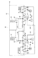
図1に示すスケルトン図を参照して、ハイブリッド駆動装置10全体の概略構成について簡単に説明する。なお、図1中の矢印F方向が自動車の前側(エンジン側)、また矢印R方向が自動車の後側(ディファレンシャル装置側)となっている。
A schematic configuration of the entire
図1に示すように、ハイブリッド駆動装置10は、前側から後側にかけて順に第1の電気モータ11、動力分配用プラネタリギヤ12、第2の電気モータ13、変速装置14が配設されている。これらは、いずれもケース15の内側に収納されるとともに、軸16(入力軸17及び出力軸18の軸心)の周囲に配設されている。なお、ケース15は、複数の分割ケースを軸方向(軸16に沿った方向)に前後に接合させることで一体に構成されている。なお、以下の説明で単に「軸方向」といった場合には、軸16に沿った方向のことをいうものとする。この軸方向は、入力軸17、出力軸18、後述の駆動シャフト31の軸方向とも一致する。
As shown in FIG. 1, the
第1の電気モータ11は、ケース15に固定されたステータ20と、このステータ20の内径側(なお、以下の説明では、ケース15の径方向の位置について、軸16に近い側を内径側、遠い側を外径側という。)において回転自在に支持されたロータ21と、を有している。この第1の電気モータ11は、そのロータ21が、後述の動力分配用プラネタリギヤ12のサンギヤS0に連結されている。このような第1の電気モータ11は、主に、サンギヤS0を介して入力される動力に基づいて発電を行い、インバータ(不図示)を介して第2の電気モータ13を駆動したり、HVバッテリ(ハイブリッド駆動用バッテリ:不図示)に対して充電を行ったりするものである。
The first
動力分配用プラネタリギヤ12は、入力軸17に対して同軸状に配置されたシングルピニオンプラネタリギヤによって構成されている。動力分配用プラネタリギヤ12は、複数のピニオンP0を支持するキャリヤCR0と、このピニオンP0に噛合するサンギヤS0と、ピニオンP0に噛合するリングギヤR0と、を有している。この動力分配用プラネタリギヤ12は、そのキャリヤCR0が入力軸17に連結され、またサンギヤS0が第1の電気モータ11のロータ21に連結され、さらにリングギヤR0が出力軸18に連結されている。このような動力分配用プラネタリギヤ12は、入力軸17を介してキャリヤCR0に入力された動力を、第1の電気モータ11の回転制御に基づいて、サンギヤS0を介して第1の電気モータ11側と、リングギヤR0を介して出力軸18側とに分配するものである。なお、第1の電気モータ11に分配された動力は発電用に、一方、出力軸18に分配された動力は自動車の駆動用に供される。
The power distribution
第2の電気モータ13は、ケース15に固定されたステータ22と、このステータ22の内径側において回転自在に支持されたロータ23と、を有している。この第2の電気モータ13は、そのロータ23が、後述の変速装置14のサンギヤS1に連結されている。この第2の電気モータ13は、前述の第1の電気モータ11と同様、インバータを介してHVバッテリに接続されている。しかし、その主たる機能は異なる。すなわち、第2の電気モータ13は、第1の電気モータ11が主に発電用に使用されるのとは異なり、主に自動車の動力(駆動力)をアシストするように駆動モータとして機能する。ただし、ブレーキ時等にはジェネレータとして機能して、車輌慣性力を電気エネルギとして回生するようになっている。
The second
変速装置14は、1個のダブルピニオンプラネタリギヤと、その1個のピニオンを共通とするシングルピニオンプラネタリギヤとからなる、いわゆるラビニョタイプのプラネタリギヤユニット24を有しており、さらに第1のブレーキB1と、第2のブレーキB2とを有している。
The
このうちプラネタリギヤユニット24は、2個のサンギヤS1,S2と、ピニオンP1及び共通のロングピニオンであるピニオンP2を支持するキャリヤCR1と、リングギヤR1とによって構成されており、2個のピニオンP1,P2のうち、ピニオンP1はサンギヤS1とリングギヤR1とに噛合し、またピニオンP2はサンギヤS2とピニオンP1とに噛合している。このプラネタリギヤユニット24は、そのリングギヤR1が第1のブレーキB1に連結され、またサンギヤS2が第2のブレーキB2に連結されている。変速装置14全体としては、入力部材となるサンギヤS1が、上述の第2の電気モータ13のロータ23に連結され、また出力部材となるキャリヤCR1が、出力軸18に連結されている。この変速装置14は、後述のように、第1,第2のブレーキB1,B2のうちの一方を係合しかつ他方を開放し、またこの逆に一方を開放しかつ他方を係合することにより、減速比の異なる2段の減速段に切り換えられるようになっている。つまり、変速装置14は、上述の第2の電気モータ13からサンギヤS1を介して入力された動力の大きさを変更して、キャリヤCR1,リングギヤR0を介して出力軸18に伝達するようになっている。本実施の形態では、第1のブレーキB1を係合し、第2のブレーキB2を開放したときにハイ(Hi)のギヤ段となり、この逆に第2のブレーキB2を係合し、第1のブレーキB1を開放することでロー(Lo)のギヤ段となる。
Of these, the
上述構成のハイブリッド駆動装置10においては、エンジンから入力軸17に入力された動力は、動力分配用プラネタリギヤ12によって第1の電気モータ11と、出力軸18とに分配される。そして、出力軸18には、変速装置14を介して第2の電気モータ13からの駆動力が伝達される。すなわち出力軸18には、エンジンからの駆動力と、第2の電気モータ13の駆動力とが合成されて出力されるようになっている。
In the
本実施の形態に係るフェールセーフ油圧回路30は、図1中の変速装置14の第1のブレーキ(第1摩擦係合要素)B1、及び第2のブレーキ(第2摩擦係合要素)B2を係脱させている。この際、フェールセーフ油圧回路30は、第1摩擦係合要素B1と第2摩擦係合要素B2の同時係合を回避するために使用されている。
The fail-safe
図2は、本発明に係るフェールセーフ油圧回路30の一例を模式的に示す図である。また、図3は、本発明に係るフェールセーフ油圧回路30が適用された油圧回路を示す図である。
FIG. 2 is a diagram schematically showing an example of the fail-safe
図3に示す油圧回路においては、モータ31によりオイルポンプ32を、またエンジンによりオイルポンプ33を駆動して油圧を発生し、発生した油圧をモジュレータバルブ34によってライン圧に調圧している。そして、調圧されたライン圧がフェールセーフ油圧回路30に供給される。フェールセーフ油圧回路30は、このライン圧に基づいて、上述の変速装置14の第1のブレーキB1、及び第2のブレーキB2を係脱して、変速装置14をHiとLoとに切り換えている。この際、フェールセーフ油圧回路30は、第1のブレーキB1と第2のブレーキB2とが同時係合しないようにしている。さらに、同時係合を回避するための構成が正常に動作しているか否かをチェックする構成も有している。以下、上述する。
In the hydraulic circuit shown in FIG. 3, an
モータ31によって駆動されるオイルポンプ32、及びエンジンによって駆動されるオイルポンプ33は、吸い上げた油を昇圧して吐出する吐出口32a,33aを有しており、この吐出口32a,33aには、油路L1が接続されている。この油路L1は、マニュアルバルブ33の入力ポートa1に接続されている。
The
モジュレータバルブ34は、スプール34aと、このスプール34aを上方に付勢するスプリング34bと、スプール34aの下端に当接されたプランジャ34cとを備える調圧弁によって構成されている。このモジュレータバルブ34は、上述の油路L1に接続された入力ポートa1と、フェールセーフ油圧回路30側の油路L2に通じる出力ポートb1と、オイルポンプ32,33の吸い込み側に油路L3を介して接続されたドレーンポートc1と、クーラー36側の油路L4に接続された出力ポートb2とを備えている。これらポートの連通度合いを制御するスプール34aには、上方の油室34dから、スプリング力に対抗するようにライン圧の直接のフィードバック圧がオリフィス経由で印加される一方、下方の油室34eから、スプリング力の重畳するようにスロットルソレノイドバルブ35が出力するスロットル圧が信号圧として印加される。このようなモジュレータバルブ34は、車両走行負荷の増加によって印加されるスロットル圧が高くなると、ドレーンポートc1への連通度合いを小さくし、出力ポートb1から出力されるライン圧を上昇させるとともに、余剰圧を出力ポートb2から油路L4を介してクーラー36等に供給する。一方、車両走行負荷の減少によって印加されるスロットル圧が低くなると、ドレーンポートc1への連通度合いを大きくしてドレーン量を増加し、出力ポートb1から出力されるライン圧を低下させることで、必要とされるライン圧を常に適正に維持している。
The
フェールセーフ油圧回路30には、上述のマニュアルバルブ34の出力ポートb1から出力されたライン圧が油路L2を介して供給される。フェールセーフ油圧回路30は、図3及び図2に示すように、第1リニアソレノイドバルブ(第1油圧生成手段)41と、第1フェールセーフバルブ42と、第1油圧サーボ43と、第1アキュムレータ44と、第1油圧スイッチ(第1油圧検知手段)45とを備えており、また第2リニアソレノイドバルブ(第2油圧生成手段)51と、第2フェールセーフバルブ52と、第2油圧サーボ53と、第2アキュムレータ54と、第2油圧スイッチ(第2油圧検知手段)55とを備えている。
The fail-safe
第1リニアソレノイドバルブ41は、上述の油路L2に接続された入力ポートa3と、油路L5に接続された出力ポートb3と、ドレーンポートc3とを有する調圧弁である。第1リニアソレノイドバルブ41は、これらポートの連通度合いを直接、制御することによって、入力ポートa3から入力されるライン圧を調圧して、出力ポートb3から係合圧として出力するように作用する。すなわち、閉状態(不図示)においては、入力ポートa3と出力ポートb3とを遮断し、かつ出力ポートb3とドレーンポートc3とを連通させるとともに、開状態(不図示)においては、入力ポート3aと出力ポート3bとを連通させ、かつ出力ポートb3とドレーンポートc3とを遮断する。そして開状態にあっては、その開度が小さいときには小さい係合圧を、開度が大きくなるほど大きな係合圧を出力ポートb3から油路L5に出力する。このように、この第1リニアソレノイドバルブ41は、切換え弁としての作用も有している。
The first
第1フェールセーフバルブ42は、スプール42aと、このスプール42aを下方に付勢するスプリング42bとを備えている。この第1リニアソレノイドバルブ41は、上述の油路L5に接続された入力ポートa4と、第1油圧サーボ43に油路L6を介して通じる出力ポートb4と、ドレーンポートc4とを有している。これら入力ポートa4、出力ポートb4、ドレーンポートc4については、スプール42aが開位置(図3の右半部に示す位置)にあるとき、入力ポートa4と出力ポートb4とが連通し、かつ出力ポートb4とドレーンポートc4とが遮断される。一方、スプール42aが閉位置(図3の左半部に示す位置)にあるとき、入力ポートa4と出力ポートb4とが遮断され、かつ出力ポートb4とドレーンポートc4とが連通される。スプール42aには、下方の油室42cから、スプリング圧に対抗するように油路L2を介してライン圧が印加される一方、上方の油室42dから、スプリング圧に重畳されるように信号圧が印加される。この信号圧としては、第2リニアソレノイドバルブ51(後述)から出力される係合圧が油路L15,L19(後述)を介して入力される。第1フェールセーフバルブ42は、他に、第2フェールセーフバルブ52(後述)から出力される係合圧が入力される入力ポートa5と、第2油圧スイッチ55(後述)に油路L7を介して通じる出力ポートb5とを有している。これら入力ポートa5と出力ポートb5とは、スプール42aが開位置にあるとき遮断され、閉位置にあるとき連通される。
The first
第1油圧サーボ43は、ピストンとシリンダとこれらの間に形成された油室(いずれも不図示)をと備えており、上述の第1フェールセーフバルブ42、油路L6を介して油室に供給される係合圧に応じて、第1のブレーキB1を係脱させるようになっている。
The first
第1アキュムレータ44は、油路L6に接続されたばね式のアキュムレータによって構成されている。第1アキュムレータ44は、第1油圧サーボ43に給排される係合圧の脈動の防止、サージ圧(急激な変動圧)の吸収等を行っている。
The
第1油圧スイッチ45は、例えばピストン式の圧力スイッチによって構成されており、上述の第1フェールセーフバルブ42と第1油圧サーボ43との間の油路L6から油路L8、第2フェールセーフバルブ52(後述)、油路L17を介して第1油圧サーボ43に接続されている。第1油圧スイッチ45は、内蔵するマイクロスイッチ(不図示)により、第1油圧サーボ43が所定の設定圧になったことを検知することができる。なお、検知結果(検知信号)は、変速装置14の変速要のECU(電子制御ユニット:不図示)に送られ、例えば、ECUにあらかじめ格納されている、第1リニアソレノイドバルブ41の電流値と第1係合圧との関係についてのマップと比較し、これにより第1フェールセーフバルブ42と第2フェールセーフバルブ52の動作が正常か否かが判断される。なお、異常であると判断された場合には、変速を禁止したり、オイルポンプ32,33の出力を低下させたりして、油圧回路全体を安全なほうにシフトするようにしている。
The first
第2リニアソレノイドバルブ51は、上述の油路L2に接続された入力ポートa13と、油路L15に接続された出力ポートb13と、ドレーンポートc13とを有する調圧弁である。第2リニアソレノイドバルブ51は、これらポートの連通度合いを直接、制御することによって、入力ポートa13から入力されるライン圧を調圧して、出力ポートb13から係合圧として出力するように作用する。すなわち、閉状態(不図示)においては、入力ポートa13と出力ポートb13とを遮断し、かつ出力ポートb13とドレーンポートc13とを連通させるとともに、開状態(不図示)においては、入力ポート13aと出力ポート13bとを連通させ、かつ出力ポートb13とドレーンポートc13とを遮断する。そして開状態にあっては、その開度が小さいときには小さい係合圧を、開度が大きくなるほど大きな係合圧を出力ポートb13から油路L15に出力する。このように、この第2リニアソレノイドバルブ51は、切換え弁としての作用も有している。
The second
第2フェールセーフバルブ52は、スプール52aと、このスプール52aを下方に付勢するスプリング52bとを備えている。この第2リニアソレノイドバルブ51は、上述の油路L15に接続された入力ポートa14と、第2油圧サーボ53に油路L16を介して通じる出力ポートb14と、ドレーンポートc14とを有している。これら入力ポートa14、出力ポートb14、ドレーンポートc14については、スプール52aが開位置(図3の右半部に示す位置)にあるとき、入力ポートa14と出力ポートb14とが連通し、かつ出力ポートb14とドレーンポートc14とが遮断される。一方、スプール52aが閉位置(図3の左半部に示す位置)にあるとき、入力ポートa14と出力ポートb14とが遮断され、かつ出力ポートb14とドレーンポートc14とが連通される。スプール52aには、下方の油室52cから、スプリング圧に対抗するように油路L2を介してライン圧が印加される一方、上方の油室52dから、スプリング圧に重畳されるように信号圧が印加される。この信号圧としては、第1リニアソレノイドバルブ41から出力される係合圧が油路L5,L9を介して入力される。第2フェールセーフバルブ52は、他に、第1フェールセーフバルブ42から出力される係合圧が入力される入力ポートa15と、第1油圧スイッチ45に油路L17を介して通じる出力ポートb15とを有している。これら入力ポートa15と出力ポート1b5とは、スプール52aが開位置にあるとき遮断され、閉位置にあるとき連通される。
The second
第2油圧サーボ53は、ピストンとシリンダとこれらの間に形成された油室(いずれも不図示)をと備えており、上述の第2フェールセーフバルブ52、油路L16を介して油室に供給される係合圧に応じて、第2のブレーキB2を係脱させるようになっている。
The second
第2アキュムレータ54は、油路L16に接続されたばね式のアキュムレータによって構成されている。第2アキュムレータ54は、第2油圧サーボ53に給排される係合圧の脈動の防止、サージ圧(急激な変動圧)の吸収等を行っている。
The
第2油圧スイッチ55は、例えばピストン式の圧力スイッチによって構成されており、上述の第2フェールセーフバルブ52と第2油圧サーボ53との間の油路L16から油路L18、第1フェールセーフバルブ42、油路L7を介して第2油圧サーボ53に接続されている。第2油圧スイッチ55は、内蔵するマイクロスイッチ(不図示)により、第2油圧サーボ53が所定の設定圧になったことを検知することができる。なお、検知結果(検知信号)は、変速装置14の変速要のECU(電子制御ユニット:不図示)に送られ、例えば、ECUにあらかじめ格納されている、第2リニアソレノイドバルブ51の電流値と第2係合圧との関係についてのマップと比較し、これにより第2フェールセーフバルブ52と第1フェールセーフバルブ42の動作が正常か否かが判断される。なお、異常であると判断された場合には、変速を禁止したり、オイルポンプ32,33の出力を低下させたりして、油圧回路全体を安全なほうにシフトするようにしている。
The second
つづいて、図2,図3を参照して、上述のフェールセーフ油圧回路30の動作を説明する。なお、図2においては、ギヤ段がハイ(Hi)の場合を実線で図示し、ギヤ段がロー(Lo)の場合を点線で図示している。なお、以下では、フェールセーフ油圧回路30に関する動作に限定して説明する。
Next, the operation of the above-described fail-safe
自動車のスイッチをオンすると、モータ31が回転し、オイルポンプ32が駆動されて吐出側の油路L1に油圧が発生する。この油圧は、モジュレータバルブ34に入力され、ライン圧として油路L2に出力される。このとき第1リニアソレノイドバルブ41及び第2リニアソレノイドバルブ51は、閉状態であり、ライン圧は、第1フェールセーフバルブ42の油室42c及び第2フェールセーフバルブ52の油室52cに入力される。これにより、第1フェールセーフバルブ42及び第2フェールセーフバルブ52は、いずれも開位置状態(図3の右半位置)となる。すなわち、第1フェールセーフバルブ42の入力ポートa4と出力ポートb4とが連通され、出力ポートb4とドレーンポートc4とが遮断される。第2フェールセーフバルブ52についても同様に、入力ポートa14と出力ポートb14とが連通され、出力ポートb14とドレーンポートc14とが遮断される。
When the automobile switch is turned on, the
ここで、エンジン始動のための反力を発生させるべく、第1のブレーキ(図1参照)を係合させる。すなわち、第1リニアソレノイドバルブ41を開状態とし、油路L2を介して供給されたライン圧を、第1係合圧として油路L5に出力し、さらにこの第1係合圧を第1フェールセーフバルブ42の連通状態の入力ポートa4及び出力ポートb4、油路L6を介して第1油圧サーボ43に供給する。このとき、第2フェールセーフバルブ52には、油路L5に出力された第1係合圧が油路L9を介して、油室52dに信号圧として入力される。これにより、第2フェールセーフバルブ52は閉位置状態(図3中の左半位置)となり、入力ポートa14と出力ポートb14とを遮断する。つまり、第2リニアソレノイドバルブ51が誤動作で開放された場合でも、第2油圧サーボ53には第2係合圧が供給されることはない。
Here, the first brake (see FIG. 1) is engaged in order to generate a reaction force for starting the engine. That is, the first
こうして、第1フェールセーフバルブ42が開位置状態、第2フェールセーフバルブ52が閉位置状態となり、第1フェールセーフバルブ42の入力ポートa5と出力ポートb5とは遮断され、第2フェールセーフバルブ52の入力ポートa15と出力ポートb15とは連通される。これにより、第1フェールセーフバルブ42から油路L6を介して第1油圧サーボ43に供給される第1係合圧が、同じ油路L6から油路L8、入力ポートa15、出力ポートb15を介して、第1油圧スイッチ45に入力される。つまり、第1油圧サーボ43に供給される第1係合圧が、第1油圧スイッチ45に入力される。そこで、例えば、第1油圧スイッチ45の設定圧を、第1のブレーキB1が係合するときの係合圧に対応するように設定しておけば、第1油圧スイッチ45をモニターすることで、第1のブレーキB1が係合したか否かを検知することができる。検知後、例えば、図1に示す第2の電気モータ13を停止制御し、第1の電気モータ11を回転制御し、この第1の電気モータ11をスターターとしてエンジンを回転させることができる。これにより、第1のブレーキB1が確実に係合されたことを検知し、直ちに、エンジンを始動させることができるので、ロスタイムを低減することができる。
Thus, the first
また、第1フェールセーフバルブ42が正常で、第2フェールセーフバルブ52が故障して開位置状態にある場合には、第1フェールセーフバルブ42からの油圧が第2フェールセーフバルブ52により遮断されるため、油圧スイッチ45の油圧は略0を示す。したがって、予め設定されたスイッチの状態(ON、OFF)と油圧スイッチ45にて検知される状態(ON、OFF)を比較することによって第1及び第2フェールセーフバルブ42,52の双方が正常に作動しているか否かを検知することができる。
Further, when the first
以上では、エンジン始動時の反力制御時に、第1油圧スイッチ45によって第1油圧サーボ43に供給される第1係合圧を検知する場合を例に説明したが、これに代えて、反力制御時に、第2のブレーキB2を使用する場合には、上述と同様に、第2油圧スイッチ55によって第2油圧サーボ53に供給される第2係合圧を検知するようにすればよい。
In the above, the case where the first engagement pressure supplied to the first
また、本発明によると、第1油圧スイッチ45及び第2油圧スイッチ55の設定圧を適宜な所定値に設定しておけば、変速装置14(図1参照)の変速時、すなわち第1のブレーキB1と第2のブレーキB2のつかみ換え時に、第1油圧サーボ43に供給される第1係合圧を第1油圧スイッチ45により検知し、また第2油圧サーボ53に供給される第2係合圧を第2油圧スイッチ55により検知することができる。つまり、つかみ換え時に、一方の油圧サーボに供給される係合圧が正常に減少し、他方の油圧サーボに供給される係合圧が正常に上昇しているかを、第1油圧スイッチ45及び第2油圧スイッチ55により確認することができる。なお、つかみ換え時には、第1油圧サーボ43と第2油圧サーボ53とに同時に係合圧が供給される場合、すなわち第1フェールセーフバルブ42と第2フェールセーフバルブ52とが同時に開位置状態となる場合があるが、このような係合圧の同時供給は、係合圧の低い部分で行われるため、フェールセーフとしての機能に支障を与えるものではない。ただし、第1フェールセーフバルブ42と第2フェールセーフバルブ52の双方が開位置状態にある場合には、これらのバルブの構造上、第1油圧スイッチ45、第2油圧スイッチ55には係合圧は供給されないので、検知が不能となる。
Further, according to the present invention, if the set pressures of the first
以下に、第1フェールセーフバルブ42、第2フェールセーフバルブ52の動作の正誤と、第1油圧スイッチ45、第2油圧スイッチ55の検知関係とを整理しておく。ただし、ライン圧が発生していて、かつ第1リニアソレノイドバルブ41及び第2リニアソレノイドバルブ51が正常に動作している場合について説明する。また、説明を簡略化するため、第1油圧スイッチ45及び第2油圧スイッチ55は、設定圧が0の場合、すなわち第1係合圧及び第2係合圧が発生しない場合にオフ、発生した場合にオンとなるものとする。このような条件のもとでは、
・第1油圧スイッチ45がオンとなるのは、第1リニアソレノイドバルブ41が開状態で、かつ第1フェールセーフバルブ42及び第2フェールセーフバルブ52が正常の場合に限られる。したがって、第1リニアソレノイドバルブ41が開状態で、かつ第1油圧スイッチ45がオンの場合は、第1フェールセーフバルブ42及び第2フェールセーフバルブ52の双方が正常であるといえる。言い換えると、第1リニアソレノイドバルブ41が開状態で、第1油圧スイッチ45がオフの場合は、第1フェールセーフバルブ42と第2フェールセーフバルブ52とのうちの少なくとも一方が異常である。
・第2油圧スイッチ55についても同様である。すなわち、第2油圧スイッチ55がオンとなるのは、第2リニアソレノイドバルブ51が開状態で、かつ第2フェールセーフバルブ52及び第1フェールセーフバルブ42が正常の場合に限られる。したがって、第2リニアソレノイドバルブ51が開状態で、かつ第2油圧スイッチ55がオンの場合は、第1フェールセーフバルブ42及び第2フェールセーフバルブ52の双方が正常であるといえる。言い換えると、第2リニアソレノイドバルブ51が開状態で、第2油圧スイッチ55がオフの場合は、第1フェールセーフバルブ42と第2フェールセーフバルブ52とのうちの少なくとも一方が異常である。
Below, the correctness of the operation of the first
The first
The same applies to the second
本実施の形態によると、上述のように、第1油圧スイッチ45及び第2油圧スイッチ55は、第1フェールセーフバルブ42及び第2フェールセーフバルブ52の正誤を検知することができる上、前述のように、第1油圧サーボ43及び第2油圧サーボ53の係合圧を検知することができる。
According to the present embodiment, as described above, the first
例えば、一方のフェールセーフバルブが正常で、他方のフェールセーフバルブが故障して開位置状態にある場合には、一方のフェールセーフバルブからの油圧が他方のフェールセーフバルブにより遮断されるため、油圧検知手段が検知する油圧は略0を示す。したがって、検知されるべき油圧が油圧検知手段にて検知されないことを見ることによって、第1及び第2フェールセーフバルブ42,52の双方が正常に作動しているか否かを検知することができる。
For example, if one failsafe valve is normal and the other failsafe valve fails and is in the open position, the oil pressure from one failsafe valve is shut off by the other failsafe valve. The oil pressure detected by the detecting means is substantially zero. Therefore, it can be detected whether or not both the first and second
さらに具体的には、第1フェールセーフバルブ42が開位置状態にあり、かつこの第1フェールセーフバルブ42を経由して第1油圧サーボ43に第1係合圧が供給された場合には、この第1係合圧が閉位置状態の第2フェールセーフバルブ52を介して第1油圧スイッチ45に入力されるので、この第1油圧スイッチ45により、第1油圧サーボ43に第1係合圧が供給されていること、そしてその第1係合圧が例えば第1油圧スイッチ45の設定圧よりも大きい場合にはこのことを検知することができる。これらを検知することにより、第1フェールセーフバルブ42を介して第1油圧サーボ43に供給されている第1係合圧が上述の設定圧よりも高い場合には、少なくとも、第1フェールセーフバルブ42及び第2フェールセーフバルブ52が正常に動作していることを確認することができる。このことは、例えば、第1のブレーキB1が係合された状態での自動車の走行中には、2個ある油圧スイッチ、すなわち第1油圧スイッチ45と第2油圧スイッチ55のうちの、第1油圧スイッチ45のみを監視すれば、第1フェールセーフバルブ42及び第2フェールセーフバルブ52を作動に異常があるか否かをチェックすることができる、ということを意味する。
More specifically, when the first
同様に、第2フェールセーフバルブ52が開位置状態にあり、かつこの第2フェールセーフバルブ52を経由して第2油圧サーボ53に第2係合圧が供給された場合には、この第2係合圧が閉位置状態の第1フェールセーフバルブ42を介して第2油圧スイッチ55に入力されるので、この第2油圧スイッチ55により、第2油圧サーボ53に第2係合圧が供給されていること、そしてその第2係合圧が例えば第2油圧スイッチ55の設定圧よりも大きい場合にはこのことを検知することができる。これらを検知することにより、第1フェールセーフバルブ42を介して第1油圧サーボ43に供給されている第1係合圧が上述の設定圧よりも高い場合には、少なくとも、第1フェールセーフバルブ52及び第2フェールセーフバルブ52が正常に動作していることを確認することができる。このことは、例えば、第2のブレーキB2が係合された状態での自動車の走行中には、2個ある油圧スイッチ、すなわち第1油圧スイッチ45と第2油圧スイッチ55のうちの、第2油圧スイッチ55のみを監視すれば、第1フェールセーフバルブ42及び第2フェールセーフバルブ52を作動に異常があるか否かをチェックすることができる、ということを意味する。
Similarly, when the second fail
なお、一方のフェールセーフバルブから出力された油圧を他方のフェールセーフバルブを介さずに検知するように油圧スイッチを配置する方法では、1つの摩擦係合要素に対するフェールセーフバルブ及びリニアソレノイドの双方が故障した場合に、異常を検知できるが、フェールセーフバルブだけが故障した場合には検知できない。 In the method of arranging the hydraulic switch so that the hydraulic pressure output from one failsafe valve is detected without passing through the other failsafe valve, both the failsafe valve and the linear solenoid for one friction engagement element are An abnormality can be detected when a failure occurs, but cannot be detected when only the failsafe valve fails.
これに対して、本実施の形態では、何れかのフェールセーフバルブ42,52が故障した時点で、異常を検知することができるので、リニアソレノイド41,51とフェールセーフバルブ42,52の双方が故障し、2つの摩擦係合要素B1,B2が同時係合することを回避することができる。
On the other hand, in this embodiment, since any failure can be detected when any of the
以上説明した実施の形態では、同時係合を避けるべき摩擦回転要素が、第1のブレーキB1,第2のブレーキB2である場合を例に説明したが、本発明はこれに限定されるものではなく、同時係合を避けるべき摩擦回転要素が、2個のクラッチである場合についても同様に適用することができ、この場合にも、上述と同様の効果を奏することができる。また、油圧検出手段として油圧スイッチ43,45を例に挙げて説明したが、油圧検出手段として、油圧スイッチ43,45に代えて油圧をリニアに検知できる油圧センサ(不図示)を採用しても、同様の効果を奏することができる。 In the embodiment described above, the case where the friction rotating elements that should avoid simultaneous engagement are the first brake B1 and the second brake B2 has been described as an example, but the present invention is not limited to this. In addition, the present invention can be similarly applied to the case where the friction rotating element that should avoid simultaneous engagement is two clutches, and in this case, the same effect as described above can be obtained. Further, although the hydraulic pressure switches 43 and 45 have been described as an example of the hydraulic pressure detection means, a hydraulic pressure sensor (not shown) capable of linearly detecting the hydraulic pressure may be adopted as the hydraulic pressure detection means instead of the hydraulic pressure switches 43 and 45. The same effect can be produced.
30 フェールセーフ油圧回路
41 油圧生成手段(第1リニアソレノイドバルブ)
42 第1フェールセーフバルブ
43 第1油圧サーボ
45 第1油圧検知手段(第1油圧スイッチ)
51 油圧生成手段(第2リニアソレノイドバルブ)
52 第2フェールセーフバルブ
53 第2油圧サーボ
55 第2油圧検知手段(第2油圧スイッチ)
B1 第1摩擦係合要素(第1のブレーキ)
B2 第2摩擦係合要素(第2のブレーキ)
30 Fail-safe
42 First fail-
51 Hydraulic pressure generating means (second linear solenoid valve)
52 Second fail-
B1 first friction engagement element (first brake)
B2 Second friction engagement element (second brake)
Claims (6)
前記第1油圧サーボへ供給する油圧を生成する第1油圧生成手段と、
前記第2油圧サーボへ供給する油圧を生成する第2油圧生成手段と、
前記第1油圧サーボに対する第1係合圧の供給を可能とする開位置と、前記第1油圧サーボに対する前記第1係合圧の供給を停止するとともに前記第1油圧サーボ内の前記第1係合圧を排出する閉位置とをとる第1フェールセーフバルブと、
前記第1フェールセーフバルブの出力油圧を検知する第1油圧検知手段と、
前記第2油圧サーボに対する第2係合圧の供給を可能とする開位置と、前記第2油圧サーボに対する前記第2係合圧の供給を停止するとともに前記第2油圧サーボ内の前記第2係合圧を排出する閉位置とをとる第2フェールセーフバルブと、
前記第2フェールセーフバルブの出力油圧を検知する第2油圧検知手段と、を備え、
前記第1油圧生成手段が生成した油圧が前記第2フェールセーフバルブに入力されると前記第2フェールセーフバルブが閉位置状態となると共に、前記第2油圧生成手段が生成した油圧が前記第1フェールセーフバルブに入力されると前記第1フェールセーフバルブが閉位置状態となる油圧回路を形成し、
前記閉位置状態にある前記第2フェールセーフバルブを経由して前記第1係合圧が前記第1油圧検知手段に入力され、
前記閉位置状態にある前記第1フェールセーフバルブを経由して前記第2係合圧が前記第2油圧検知手段に入力される、
ことを特徴とするフェールセーフ油圧回路。 In a fail-safe hydraulic circuit for avoiding simultaneous engagement of a first friction engagement element engaged / disengaged by a first hydraulic servo and a second friction engagement element engaged / disengaged by a second hydraulic servo,
A first hydraulic generation means for generating the hydraulic pressure supplied to said first hydraulic servo,
Second hydraulic pressure generating means for generating hydraulic pressure to be supplied to the second hydraulic servo;
An open position that enables the supply of the first engagement pressure to the first hydraulic servo, the supply of the first engagement pressure to the first hydraulic servo is stopped, and the first engagement in the first hydraulic servo is stopped. A first failsafe valve that takes a closed position for discharging the combined pressure;
First hydraulic pressure detection means for detecting an output hydraulic pressure of the first failsafe valve;
An open position that enables the supply of the second engagement pressure to the second hydraulic servo, the supply of the second engagement pressure to the second hydraulic servo is stopped, and the second engagement in the second hydraulic servo is stopped. A second fail-safe valve that takes a closed position for discharging the combined pressure;
Second oil pressure detecting means for detecting the output oil pressure of the second failsafe valve,
Together with the said second fail-safe valve and the first hydraulic generating means hydraulic pressure generated is input to the second fail-safe valve is in the closed position state, hydraulic pressure is first generated said second hydraulic generating means Forming a hydraulic circuit in which the first fail-safe valve enters a closed position when input to the fail-safe valve ;
The first engagement pressure is input to the first hydraulic pressure detection means via the second fail-safe valve in the closed position ;
The second engagement pressure is input to the second hydraulic pressure detection means via the first failsafe valve in the closed position ;
A fail-safe hydraulic circuit characterized by that.
ことを特徴とする請求項1に記載のフェールセーフ油圧回路。 A first linear solenoid valve as the first hydraulic pressure generating means for supplying the first engagement pressure to the first hydraulic servo via the first failsafe valve, and via the second failsafe valve A second linear solenoid valve as the second hydraulic pressure generating means for supplying the second engagement pressure to the second hydraulic servo,
The fail-safe hydraulic circuit according to claim 1.
前記第1フェールセーフバルブを閉状態とする前記第2係合圧は、前記第2リニアソレノイドバルブと前記第2フェールセーフバルブとを連結する油路から供給される、
ことを特徴とする請求項2に記載のフェールセーフ油圧回路。 The first engagement pressure for closing the second failsafe valve is supplied from an oil passage connecting the first linear solenoid valve and the first failsafe valve;
The second engagement pressure for closing the first failsafe valve is supplied from an oil passage connecting the second linear solenoid valve and the second failsafe valve.
The fail-safe hydraulic circuit according to claim 2.
閉位置状態にある前記第1フェールセーフバルブを経由して前記第2油圧検知手段に入力される前記第2係合圧は、前記第2フェールセーフバルブと前記第2油圧サーボとを連結する油路から供給される、
ことを特徴とする請求項3に記載のフェールセーフ油圧回路。 The first engagement pressure that is input to the first hydraulic pressure detection means via the second failsafe valve in the closed position is oil that connects the first failsafe valve and the first hydraulic servo. Supplied from the road,
The second engagement pressure input to the second hydraulic pressure detection means via the first failsafe valve in the closed position is oil that connects the second failsafe valve and the second hydraulic servo. Supplied from the road,
The fail-safe hydraulic circuit according to claim 3 .
ことを特徴とする請求項1ないし4のいずれか1項に記載のフェールセーフ油圧回路。 The first friction engagement element and the second friction engagement element are brakes;
The fail-safe hydraulic circuit according to any one of claims 1 to 4, wherein the hydraulic circuit is a fail-safe hydraulic circuit.
ことを特徴とする請求項1ないし4のいずれか1項に記載のフェールセーフ油圧回路。 The first friction engagement element and the second friction engagement element are clutches;
The fail-safe hydraulic circuit according to any one of claims 1 to 4, wherein the hydraulic circuit is a fail-safe hydraulic circuit.
Priority Applications (5)
| Application Number | Priority Date | Filing Date | Title |
|---|---|---|---|
| JP2003371354A JP4587657B2 (en) | 2003-10-30 | 2003-10-30 | Fail-safe hydraulic circuit |
| CNB2004100882291A CN100526690C (en) | 2003-10-30 | 2004-10-21 | Self-regulating brake oil pressure loop |
| DE102004052073A DE102004052073B4 (en) | 2003-10-30 | 2004-10-26 | Fail-safe hydraulic circuit |
| KR1020040085557A KR100833128B1 (en) | 2003-10-30 | 2004-10-26 | Failsafe hydraulic circuit |
| US10/976,237 US7128676B2 (en) | 2003-10-30 | 2004-10-29 | Failsafe hydraulic circuit |
Applications Claiming Priority (1)
| Application Number | Priority Date | Filing Date | Title |
|---|---|---|---|
| JP2003371354A JP4587657B2 (en) | 2003-10-30 | 2003-10-30 | Fail-safe hydraulic circuit |
Publications (2)
| Publication Number | Publication Date |
|---|---|
| JP2005133856A JP2005133856A (en) | 2005-05-26 |
| JP4587657B2 true JP4587657B2 (en) | 2010-11-24 |
Family
ID=34510408
Family Applications (1)
| Application Number | Title | Priority Date | Filing Date |
|---|---|---|---|
| JP2003371354A Expired - Fee Related JP4587657B2 (en) | 2003-10-30 | 2003-10-30 | Fail-safe hydraulic circuit |
Country Status (5)
| Country | Link |
|---|---|
| US (1) | US7128676B2 (en) |
| JP (1) | JP4587657B2 (en) |
| KR (1) | KR100833128B1 (en) |
| CN (1) | CN100526690C (en) |
| DE (1) | DE102004052073B4 (en) |
Families Citing this family (30)
| Publication number | Priority date | Publication date | Assignee | Title |
|---|---|---|---|---|
| JP3783715B2 (en) * | 2004-01-22 | 2006-06-07 | トヨタ自動車株式会社 | Control device for hybrid vehicle |
| JP4887677B2 (en) * | 2005-07-19 | 2012-02-29 | トヨタ自動車株式会社 | Hydraulic control device for automatic transmission for vehicle |
| KR100704788B1 (en) * | 2005-08-18 | 2007-04-10 | 현대자동차주식회사 | Hybrid vehicles |
| US7410437B2 (en) * | 2005-08-31 | 2008-08-12 | Caterpillar Inc. | Planetary drive arrangement |
| US7288039B2 (en) * | 2005-10-31 | 2007-10-30 | General Motors Corporation | Multiplexed pressure switch system for an electrically variable hybrid transmission |
| JP2007139114A (en) * | 2005-11-21 | 2007-06-07 | Toyota Motor Corp | Power output device, vehicle having the same and control method for power output device |
| JP4696875B2 (en) * | 2005-11-28 | 2011-06-08 | トヨタ自動車株式会社 | Hydraulic control device for automatic transmission for vehicle |
| JP4642661B2 (en) * | 2006-01-11 | 2011-03-02 | トヨタ自動車株式会社 | Transmission control device |
| JP4722710B2 (en) | 2006-01-11 | 2011-07-13 | トヨタ自動車株式会社 | Hydraulic control device for transmission |
| JP4258521B2 (en) | 2006-01-31 | 2009-04-30 | トヨタ自動車株式会社 | Vehicle drive device |
| JP4341631B2 (en) * | 2006-01-31 | 2009-10-07 | トヨタ自動車株式会社 | Vehicle abnormality determination device |
| US7894965B2 (en) * | 2006-11-29 | 2011-02-22 | Chrysler Group Llc | Swap shift control scheme for an automatic transmission |
| US7878932B2 (en) * | 2007-09-13 | 2011-02-01 | GM Global Technology Operations LLC | Method and apparatus to monitor a valve adapted to control mode to gear transitions during operation of an electro-mechanical transmission |
| US7869924B2 (en) * | 2007-10-10 | 2011-01-11 | GM Global Technology Operations LLC | Method and apparatus to monitor a flow management valve of an electro-mechanical transmission |
| US7980980B2 (en) * | 2007-11-14 | 2011-07-19 | GM Global Technology Operations LLC | Hybrid powertrain |
| JP2009133428A (en) * | 2007-11-30 | 2009-06-18 | Aisin Aw Co Ltd | Vehicle drive unit |
| JP4881342B2 (en) * | 2008-03-31 | 2012-02-22 | ジヤトコ株式会社 | Hydraulic pressure control device for automatic transmission and failure determination method for its fail-safe valve |
| JP4785888B2 (en) * | 2008-04-07 | 2011-10-05 | 三菱電機株式会社 | Transmission control system |
| DE102009005753A1 (en) * | 2009-01-23 | 2010-07-29 | Daimler Ag | Hydraulic control for an automated transmission |
| JP5139353B2 (en) * | 2009-03-10 | 2013-02-06 | アイシン・エィ・ダブリュ株式会社 | Hydraulic control device for automatic transmission |
| CN101893044B (en) * | 2010-07-21 | 2012-02-15 | 吉林大学 | Pneumatic, manual and automatic integrated clutch control system |
| JP5282288B2 (en) * | 2010-12-28 | 2013-09-04 | アイシン・エィ・ダブリュ株式会社 | Hydraulic control device for transmission |
| JP2015020488A (en) * | 2013-07-17 | 2015-02-02 | トヨタ自動車株式会社 | Control device of hybrid vehicle |
| WO2015099125A1 (en) | 2013-12-26 | 2015-07-02 | アイシン・エィ・ダブリュ株式会社 | Oil-pressure control device for automatic transmission |
| JP6027992B2 (en) * | 2014-02-18 | 2016-11-16 | 本田技研工業株式会社 | Hydraulic control device |
| KR101574966B1 (en) | 2014-04-07 | 2015-12-08 | 현대오트론 주식회사 | Method and Apparatus for Supporting the Function of Fail Safe Valve in Valve Body of Automatic Transmisson |
| JP6119706B2 (en) | 2014-09-24 | 2017-04-26 | マツダ株式会社 | Hydraulic control device for automatic transmission |
| JP6241445B2 (en) * | 2015-04-17 | 2017-12-06 | トヨタ自動車株式会社 | Power transmission control device |
| CN108291632B (en) * | 2015-12-09 | 2020-01-21 | 爱信艾达株式会社 | Hydraulic control device for automatic transmission |
| JP7014071B2 (en) * | 2018-07-12 | 2022-02-01 | トヨタ自動車株式会社 | Clutch disconnection device |
Citations (2)
| Publication number | Priority date | Publication date | Assignee | Title |
|---|---|---|---|---|
| JP2001059570A (en) * | 1999-08-20 | 2001-03-06 | Jatco Transtechnology Ltd | Shift controller at the time of trouble in automatic transmission |
| JP2001248723A (en) * | 2000-03-01 | 2001-09-14 | Honda Motor Co Ltd | Control device for vehicular automatic transmission |
Family Cites Families (15)
| Publication number | Priority date | Publication date | Assignee | Title |
|---|---|---|---|---|
| US78134A (en) * | 1868-05-19 | Assig-nob to himself | ||
| US64854A (en) * | 1867-05-21 | Petera | ||
| US64849A (en) * | 1867-05-21 | William h | ||
| US84233A (en) * | 1868-11-17 | Improvement in gun-locks | ||
| US3623568A (en) * | 1968-05-31 | 1971-11-30 | Nissan Motor | Electromechanical power train system for an automotive vehicle |
| DK0837311T3 (en) * | 1996-05-02 | 2004-11-29 | Eisai Co Ltd | Non-contact inspection apparatus |
| JP3695257B2 (en) * | 1999-10-19 | 2005-09-14 | 日産自動車株式会社 | Fail-safe system for direct acting valve type automatic transmission |
| JP3592982B2 (en) * | 2000-01-25 | 2004-11-24 | 本田技研工業株式会社 | Hybrid vehicle control device |
| JP3580257B2 (en) * | 2001-02-05 | 2004-10-20 | トヨタ自動車株式会社 | Hybrid car |
| JP2003016433A (en) | 2001-07-03 | 2003-01-17 | Nec Corp | Method, system, and program for living-body identification by fingerprint collation |
| JP2003049937A (en) * | 2001-08-07 | 2003-02-21 | Aisin Aw Co Ltd | Hydraulic pressure control device of automatic transmission |
| JP4008685B2 (en) | 2001-09-28 | 2007-11-14 | ジヤトコ株式会社 | Hydraulic control device for automatic transmission |
| JP3707411B2 (en) | 2001-09-28 | 2005-10-19 | トヨタ自動車株式会社 | Power output apparatus and automobile equipped with the same |
| US7223200B2 (en) | 2001-10-22 | 2007-05-29 | Toyota Jidosha Kabushiki Kaisha | Hybrid-vehicle drive system and operation method with a transmission |
| JP3650089B2 (en) | 2002-08-02 | 2005-05-18 | トヨタ自動車株式会社 | Hybrid drive device and automobile equipped with the same |
-
2003
- 2003-10-30 JP JP2003371354A patent/JP4587657B2/en not_active Expired - Fee Related
-
2004
- 2004-10-21 CN CNB2004100882291A patent/CN100526690C/en not_active Expired - Fee Related
- 2004-10-26 KR KR1020040085557A patent/KR100833128B1/en not_active IP Right Cessation
- 2004-10-26 DE DE102004052073A patent/DE102004052073B4/en not_active Expired - Fee Related
- 2004-10-29 US US10/976,237 patent/US7128676B2/en not_active Expired - Fee Related
Patent Citations (2)
| Publication number | Priority date | Publication date | Assignee | Title |
|---|---|---|---|---|
| JP2001059570A (en) * | 1999-08-20 | 2001-03-06 | Jatco Transtechnology Ltd | Shift controller at the time of trouble in automatic transmission |
| JP2001248723A (en) * | 2000-03-01 | 2001-09-14 | Honda Motor Co Ltd | Control device for vehicular automatic transmission |
Also Published As
| Publication number | Publication date |
|---|---|
| CN100526690C (en) | 2009-08-12 |
| US20050137043A1 (en) | 2005-06-23 |
| US7128676B2 (en) | 2006-10-31 |
| DE102004052073A1 (en) | 2005-05-25 |
| CN1619193A (en) | 2005-05-25 |
| KR20050041900A (en) | 2005-05-04 |
| DE102004052073B4 (en) | 2009-12-03 |
| JP2005133856A (en) | 2005-05-26 |
| KR100833128B1 (en) | 2008-05-28 |
Similar Documents
| Publication | Publication Date | Title |
|---|---|---|
| JP4587657B2 (en) | Fail-safe hydraulic circuit | |
| JP4722710B2 (en) | Hydraulic control device for transmission | |
| JP4506655B2 (en) | Hydraulic control device for automatic transmission for vehicle | |
| US7137924B2 (en) | Control system for hybrid vehicles | |
| US8032274B2 (en) | Diagnostic system for automatic transmission | |
| US9005064B2 (en) | Vehicle | |
| JP5212408B2 (en) | Hydraulic control device for automatic transmission | |
| US8360220B2 (en) | Power transmission device and vehicle having the same | |
| US8348797B2 (en) | Hydraulic clutch control system | |
| US20070240776A1 (en) | Hydraulic pressure control system for automatic transmission device | |
| JP2007205439A (en) | Hydraulic control device for vehicle | |
| JP5282288B2 (en) | Hydraulic control device for transmission | |
| US11192551B2 (en) | Vehicle control device | |
| JP4642661B2 (en) | Transmission control device | |
| CN111971493B (en) | Oil supply device and vehicle drive transmission device | |
| JP7343428B2 (en) | Hybrid vehicle drive system | |
| JP4831187B2 (en) | Automatic transmission abnormality detection device | |
| JPH09105457A (en) | Controller for continuously variable transmission | |
| JP4789638B2 (en) | Power output device and vehicle equipped with the same | |
| JP4735215B2 (en) | Hydraulic control device for automatic transmission for vehicle | |
| JP4761296B2 (en) | Hydraulic control device for transmission | |
| JP5515974B2 (en) | Hydraulic control device |
Legal Events
| Date | Code | Title | Description |
|---|---|---|---|
| A711 | Notification of change in applicant |
Free format text: JAPANESE INTERMEDIATE CODE: A711 Effective date: 20050616 |
|
| A521 | Written amendment |
Free format text: JAPANESE INTERMEDIATE CODE: A821 Effective date: 20050616 |
|
| A621 | Written request for application examination |
Free format text: JAPANESE INTERMEDIATE CODE: A621 Effective date: 20060928 |
|
| A977 | Report on retrieval |
Free format text: JAPANESE INTERMEDIATE CODE: A971007 Effective date: 20090430 |
|
| A131 | Notification of reasons for refusal |
Free format text: JAPANESE INTERMEDIATE CODE: A131 Effective date: 20091027 |
|
| A521 | Written amendment |
Free format text: JAPANESE INTERMEDIATE CODE: A523 Effective date: 20091228 |
|
| RD02 | Notification of acceptance of power of attorney |
Free format text: JAPANESE INTERMEDIATE CODE: A7422 Effective date: 20100106 |
|
| TRDD | Decision of grant or rejection written | ||
| A01 | Written decision to grant a patent or to grant a registration (utility model) |
Free format text: JAPANESE INTERMEDIATE CODE: A01 Effective date: 20100907 |
|
| A01 | Written decision to grant a patent or to grant a registration (utility model) |
Free format text: JAPANESE INTERMEDIATE CODE: A01 |
|
| A61 | First payment of annual fees (during grant procedure) |
Free format text: JAPANESE INTERMEDIATE CODE: A61 Effective date: 20100907 |
|
| R150 | Certificate of patent or registration of utility model |
Free format text: JAPANESE INTERMEDIATE CODE: R150 |
|
| FPAY | Renewal fee payment (event date is renewal date of database) |
Free format text: PAYMENT UNTIL: 20130917 Year of fee payment: 3 |
|
| LAPS | Cancellation because of no payment of annual fees |