JP4587648B2 - Recording medium holder and electronic card system - Google Patents
Recording medium holder and electronic card system Download PDFInfo
- Publication number
- JP4587648B2 JP4587648B2 JP2003149777A JP2003149777A JP4587648B2 JP 4587648 B2 JP4587648 B2 JP 4587648B2 JP 2003149777 A JP2003149777 A JP 2003149777A JP 2003149777 A JP2003149777 A JP 2003149777A JP 4587648 B2 JP4587648 B2 JP 4587648B2
- Authority
- JP
- Japan
- Prior art keywords
- memory card
- unit
- information
- recording medium
- medium
- Prior art date
- Legal status (The legal status is an assumption and is not a legal conclusion. Google has not performed a legal analysis and makes no representation as to the accuracy of the status listed.)
- Expired - Fee Related
Links
Images


Landscapes
- Storage Device Security (AREA)
- Calculators And Similar Devices (AREA)
Description
【0001】
【発明の属する技術分野】
本発明は、情報を記憶するための情報記録媒体を保持する保持装置に関する。
【0002】
【従来の技術】
従来よりデジタル情報を記憶するためにフレキシブルディスク(FD)などの記録媒体が用いられている。
FDに記憶されているデジタル情報を利用者が容易に知ることができるように、記憶されているデジタル情報の内容を示すタイトルやインデックスなどの情報が記載されたシールがFDの外面に貼付される。利用者は、貼付されたシールを見ることにより、必要なFDを探し出す。
【0003】
しかしながら、記録媒体の小型化が進み、記録媒体に貼付するシールがさらに小さくなり、シールに十分な情報を記載することができない、又はシールを貼付するスペースが記録媒体上にないなどの問題点がある。
このような問題点を解決するために、特開平2−115996号公報によると、PCカード表面にデータ内容を表示する表示部を設け、表示部に表示された情報によりカードを識別する技術が開示されている。
【0004】
また、特開平4−367090号公報によると、メモリカードに液晶表示部を設け、記憶しているタイトルなどのデータを液晶表示部に表示する技術が開示されている。これらの技術は、ともにカード自体に内容を表示させることにより、シールに代替させている。
また、特開2001−101356号公報によると、PCカードアダプタにLCDを設け、このLCDにカードに記憶した画像や撮影日時等の付加情報を表示する技術が開示されている。
【0005】
さらに、特開2000−29998号公報によると、複数枚のメモリカードを装着できる記録再生装置が開示されており、前記記録再生装置は、動作中のカードの内容を表示する表示部を備えている。また、特開2000−32582号公報によると、ヘッドバンド部にチェンジャー機能を持たせて複数枚のメモリカードを収納し、メモリカードを選択して再生する手段を内蔵するヘッドホーン装置が開示されている。これらの技術は、記録媒体を保持するホルダーにその内容を表示させるものである。
【0006】
【特許文献1】
特開平2−115996号公報
【0007】
【特許文献2】
特開平4−367090号公報
【0008】
【特許文献3】
特開2001−101356号公報
【0009】
【特許文献4】
特開2000−29998号公報
【0010】
【特許文献5】
特開2000−32582号公報
【0011】
【発明が解決しようとする課題】
しかしながら、上記の従来技術によると、記録媒体、アダプタ、再生装置などに、記録媒体の内容を示す情報を表示することができるので、記録媒体にシールを貼付する場合の問題点は解決されるものの、利用者が管理する記録媒体の数が多くなると、必要な記録媒体を即座に探し出すことは困難であるという問題点がある。
【0012】
本発明は、上記の問題点を解決し、利用者が管理する記録媒体の枚数の如何に関わらず利用者が必要とする記録媒体をより容易に探し出すことができる記録媒体ホルダー及び電子カードシステムを提供することを目的とする。
【0013】
【課題を解決するための手段】
本発明は、複数枚の記録媒体を効率的にかつ安全に管理することができる記録媒体ホルダーであって、記録媒体に格納された情報が秘密情報である場合であっても、安全に情報を提示できることを目的としている。利用者が記録媒体を複数枚所有している場合に、その中から必要な記録媒体を即座に探すことができるように、記録媒体ホルダーは、記録媒体の内容を表示する手段と、記録媒体の内容が秘密情報である場合に、記録媒体の内容の表示が許可されているときにのみ、記録媒体の内容を表示する手段とを備えることを特徴とする。
【0014】
前記記録媒体ホルダーは、
(1)複数枚の記録媒体を格納する記録媒体格納部と、
(2)記録媒体格納部に格納されている複数の記録媒体をそれぞれアイコンで表示する液晶表示部と、
(3)液晶表示部に表示されたアイコンをペン等でクリックすると、
初めてクリックされた場合には、そのアイコンに対応する記録媒体のID情報、タイトル情報、インデックス情報等を記録媒体から読み出して液晶表示部に表示するとともに、
2回目以降、クリックされた場合には、そのアイコンに対応するカードのID情報、タイトル情報、インデックス情報等を記憶部から読み出して液晶表示部にて表示する情報表示部とを備える。
【0015】
また、本発明は、カードを機器に挿入することなく、利用者はカードの中身を確認することができ、また複数のカードの中から特定のカードを抽出することができるカード及び抽出装置から構成される電子カードシステムである。従来技術によると、管理するカードの枚数が増えると、その中から必要とするカードを探すことは困難である。例えば、カードの空き容量などは、カードをパソコンなどの機器に挿入しなくては知ることができず、複数のカードから最も空き容量の少ないカードを特定する作業は、手間がかかる。このように、従来技術によると、特定のデータが入ったカードや空き容量の大きいカードなどを即座に探すことは困難である。本発明は、このような問題を解決する。
【0016】
本発明は、他の機器に接触することなく電源供給を受けることが可能で書き換え可能なメモリ機能を有する電子カードと、内部に電源を保持することで電子カードに電源供給を行うことが可能な抽出装置からなる電子カードシステムであって、電子カードは、抽出装置から送出されるメッセージによって、ユーザに対し注意を促すことができる。
【0017】
具体的には、電子カードは、抽出装置から送信されるデータを受信する。次に、電子カードは、電子カード自身の持つデータ、例えば、電子カード名、残り容量、所有者名などを抽出装置に返信する。ユーザが選択した抽出規準に基づき、抽出装置は、電子カードを特定する。次に、抽出装置は、特定した電子カードにカードIDとともに抽出メッセージを送信する。次に、抽出メッセージを受信した電子カードは、自身の持つ機能、例えば、発光、振動、音声出力を用いて、ユーザに対して、抽出されたことを通知する。
【0018】
また、本発明は、他の機器に接触することなく電源供給を受けることが可能で書き換え可能なメモリ機能を有する電子カードと、内部に電源を保持することで電子カードに電源供給を行うことが可能で情報表示部を保持する抽出装置とからなる電子カードシステムであって、電子カードの情報、例えば、カードID、タイトル情報、残り容量などを情報表示部に表示することを特徴とする。
【0019】
ここで、抽出装置から送信されるデータを電子カードが受信し、電子カードの情報を抽出装置に返信し、抽出装置は、電子カードの情報を情報表示部に表示する。
【0020】
【発明の実施の形態】
1.第1の実施の形態
本発明に係る1の実施の形態としてのメモリカードホルダー10について説明する。
1.1 メモリカードホルダー10
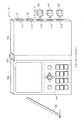
メモリカードホルダー10は、図1にその外観図を示すように、最大5枚分のメモリカードを保持するための手帳型の保持装置である。メモリカードホルダー10は、入力表示部10aと接続部10bとカード保持部10cとから構成され、入力表示部10aとカード保持部10cとは、接続部10bにより接続されている。接続部bは、折り曲げ可能であり、接続部10bが折り曲げられることにより、カード保持部10cが、入力表示部10aの表面を覆う。
【0021】
通常、メモリカードホルダー10は、図1に示すように、入力表示部10aとカード保持部10cとが開いた状態で、利用者により使用される。
カード保持部10cは、その側面部に5個のカード接続部111〜115を備えており、各カード接続部に1枚のメモリカードが挿入され、挿入されたメモリカードとメモリカードホルダー10とが電気的に接続される。この図において、カード接続部111〜112には、メモリカード21〜22がそれぞれ挿入されて接続されている。カード接続部113〜115には、メモリカードは挿入されていない。
【0022】
入力表示部10aは、その正面部にテンキー、電源ON/OFFキー、選択決定キー、カーソル移動キー、及びその他のキーを含んで構成される入力部101と、情報を液晶により表示し、また操作ペン30により利用者からの操作を受け付けるタッチパネルタイプの表示部102とを備えている。
メモリカードホルダー10は、図2にブロック図を示すように、入力部101、表示部102、認証部103、制御部104、情報記憶部105及びカード接続部111〜115から構成されている。
【0023】
メモリカードホルダー10は、具体的には、マイクロプロセッサ、ROM、RAM、液晶ディスプレィユニット、その他を含むコンピュータシステムである。前記RAMには、コンピュータプログラムが記憶されている。前記マイクロプロセッサが、前記コンピュータプログラムに従って動作することにより、メモリカードホルダー10は、その機能を達成する。
【0024】
(1)情報記憶部105
情報記憶部105は、図3に一例として示すように、機器パスワードを記憶するための領域と、媒体情報領域151〜155を含んで構成される。
機器パスワードは、メモリカードホルダー10に固有に設定されたパスワードであり、あらかじめ当該領域に書き込まれている。
【0025】
ここで、機器パスワードは、機器パスワードを知る利用者(通常、メモリーカードホルダーの持ち主)のみにより、メモリカードホルダーの利用を許可するために用いられる。機器パスワードを知らない第三者が、メモリーカードホルダーを不正に利用することはできない。
媒体情報領域151〜155は、それぞれ、カード接続部111〜115に対応しており、カード接続部111〜115に挿入されて接続されているメモリカードに記憶されている各種情報を記憶するための領域である。
【0026】
媒体情報領域151は、この図に示すように、媒体ID、媒体種別情報、媒体名称、媒体アイコン情報及び図示していないその他の情報を記憶するための部分領域を備えている。
媒体情報領域152〜155についても同様である。
(2)表示部102
表示部102は、液晶により情報を表示する液晶パネルと、その上面に設けられ接触により接触位置を検出するタッチパネルとからなる二重構造のパネルを有し、一例として、図4及び図6にそれぞれ示す画面161及び画面171を、制御部104の制御により表示する。
【0027】
また、表示部102は、利用者により操作ペン30を用いて、画面の一部が押下された場合に、押下された位置に表示している画像や文字列に対応する指示情報を制御部104へ出力する。
(画面161)
画面161は、スロットアイコン161a、161b、・・・、161eと、媒体情報表示画面161fと、検索ボタン161gと、終了ボタン161hとから構成されている。
【0028】
スロットアイコン161a、161b、・・・、161eは、それぞれ、カード接続部111〜115に対応しており、カード接続部111〜115にメモリカードが挿入されて電気的に接続されているか否かを示している。
画面161に表示される可能性のある様々なスロットアイコンをその意味とともに図5に示す。
【0029】
この図に示すスロットアイコンI101は、対応するカード接続部にメモリカードが挿入されていないことを示している。また、スロットアイコンI102は、対応するカード接続部にメモリカードが挿入されて電気的に接続されていることを示している。
また、スロットアイコンI103は、対応するカード接続部に挿入されて接続されているメモリカードについて、当該メモリカードとメモリカードホルダー10との間の相互機器認証において、認証が失敗したことを示している。
【0030】
また、スロットアイコンI101とスロットアイコンI102とが、短時間で繰り返し切り換えて表示されている場合は、スロットアイコンの点滅を示している。このスロットアイコンの点滅の意味については、後述する。
また、スロットアイコンI104〜I106は、それぞれ、対応するカード接続部に挿入されて接続されているメモリカードにあらかじめ記憶されている媒体アイコンである。スロットアイコンI104〜I106は、このようにメモリカード自身がスロットアイコンを記憶している特別なメモリカードについてのみ表示されるものである。なお、スロットアイコンI102は、対応するカード接続部に挿入されて接続されているメモリカードが、自身で媒体アイコンを記憶していない場合に、表示される標準的なアイコンである。
【0031】
なお、第1の実施の形態では、メモリカードにあらかじめアイコンが記憶されている場合を説明しているが、それに限定されない。例えば、メモリカードホルダーは、あらかじめ代表的なカードタイプの専用アイコンを記憶しており、接続部に、そのカードが接続された場合は、標準的なアイコンではなく、そのカードの専用アイコンを表示するようにしてもよい。
【0032】
媒体情報表示画面161fは、接続されているメモリカードのうち、利用者により選択されたものについて、当該メモリカードに記憶されている各種情報を表示している。図4に示すように、媒体情報表示画面161fは、5個の表示項目と、スクロールバーとから構成されている。5個の表示項目に表示される情報は、この図に一例として示すように、媒体ID、媒体種別情報、媒体名称、媒体更新日、媒体タイトルの5個のみである。当該メモリカードに記憶されている情報には、他の情報も含まれている。これらの他の情報の媒体情報表示画面161fへの表示は、操作ペン30を用いたスクロールバーの操作により行われる。スクロールバーについては、パーソナルコンピュータなどの画面においてよく用いられるものであり、公知であるので、詳細の説明は省略する。
【0033】
検索ボタン161gは、後述する検索処理を起動するために利用者により操作される。
終了ボタン161hは、メモリカードホルダー10による処理を終了し、電源をOFFとするために、利用者により操作される。
(画面171)
画面171は、図6に一例として示すように、スロットアイコン171a、171b、・・・、171eと、検索項目入力画面171fとから構成されている。
【0034】
スロットアイコン171a、171b、・・・、171eは、それぞれ、図4に示されているスロットアイコン161a、161b、・・・、161eと同じものである。ただし、スロットアイコン171a、171b、・・・、171eのうち、スロットアイコン171a及び171cは、それぞれ、点滅していることを示している。これらの点滅は、該当するメモリカードが、後述する検索処理により検索条件に合致すると判断されたことを示している。
【0035】
検索項目入力画面171fは、図6に示すように、検索条件入力部171j、171k及び171m、検索開始ボタン171g、終了ボタン171h、及び一致件数表示領域171iから構成されており、検索条件入力部171jは、検索項目選択部と、検索キーワード入力部と、検索方式選択部とを含む。
検索項目選択部は、検索項目入力領域171pとメニュー表示ボタン171qとから構成されている。検索項目入力領域171pは、メモリカードに記憶されている情報を指定するためのものであり、媒体ID、媒体種別情報、媒体名称、その他の情報から1個を利用者が選択する。メニュー表示ボタン171qは、媒体ID、媒体種別情報、媒体名称、その他の情報などの選択肢から構成されるメニュー171rを表示するために操作される。メニュー171rが表示されると、利用者は、メニュー171rを構成する選択肢から1個を選択する。
【0036】
検索キーワード入力部は、利用者から検索対象となる1個以上の文字列の入力を受け付ける領域である。
検索方式選択部は、利用者により「AND条件」又は「OR条件」の入力を受け付ける。「AND条件」又は「OR条件」は、それぞれ、検索キーワード入力部に、2個以上の文字列の入力が受け付られた場合の条件を示す。
【0037】
具体的には、検索項目選択部において「媒体ID」が選択され、検索キーワード入力部において「SD0001 SD0002」が入力され、検索方式選択部において「OR」が選択された場合には、
検索条件「検索ID=「SD0001」 OR 検索ID=「SD0002」」が指定されたものとみなす。
【0038】
検索条件入力部171k及び171mは、検索条件入力部171jと同様であり、それぞれ、検索項目選択部と、検索キーワード入力部と、検索方式選択部とを含む。
例えば、検索条件入力部171j及び検索条件入力部171kにおいて、それぞれ検索条件が選択され、入力された場合には、
「検索条件入力部171jにより選択入力された検索条件」
AND 「検索条件入力部171kにより選択入力された検索条件」が指定されたものとみなす。
【0039】
検索条件入力部171j〜検索条件入力部171mにおいて、それぞれ検索条件が選択され、入力された場合においても同様である。
検索開始ボタン171gは、利用者により操作され、上記により選択、入力された検索条件による検索処理を開始するために用いられる。
終了ボタン171hは、利用者により操作され、検索処理を終了するために用いられる。
【0040】
一致件数表示領域171iは、検索処理により検索が行われた結果、選択、入力された検索条件に合致するメモリカードの数を表示する。
(3)カード接続部111〜115
カード接続部111は、メモリカードを収容し保持する。収容されたメモリカードは、メモリカードホルダー10に電気的に接続される。利用者は、カード接続部111に、メモリカードを挿入して接続させる。メモリカードが接続されると、カード接続部111は、制御部104に制御の元に、メモリカードから各種情報を読み出し、読み出した情報を制御部104へ出力する。
【0041】
カード接続部112〜115についても、カード接続部111と同様であるので、ここでは説明を省略する。
(4)入力部101
入力部101は、テンキー、電源ON/OFFキー、選択決定キー、カーソル移動キー、及びその他のキーを含んで構成される。テンキー、電源ON/OFFキー、選択決定キー、カーソル移動キー、及びその他のキーは、利用者により操作され、各キーに対応する指示情報を制御部104へ出力する。
【0042】
(5)認証部103
認証部103は、制御部104の制御により、カード接続部111に接続されたメモリカードとの間で相互に、チャレンジ−レスポンス型の機器認証を行う。なお、チャレンジ−レスポンス型の機器認証については、公知であるので、説明を省略する。
【0043】
認証部103は、また、制御部104の制御により、カード接続部112〜115に接続されたメモリカードとの間で、上記と同様に、相互にチャレンジ−レスポンス型の機器認証を行う。
(6)制御部104
制御部104は、入力部101、表示部102、認証部103、情報記憶部105及びカード接続部111〜115を制御する。制御の詳細については、後述する。
【0044】
1.2 メモリカード21
メモリカード21は、図7に示すように、入出力部201、認証部202及び情報記憶部203から構成されている。
(1)入出力部201
メモリカード21がメモリカードホルダー10の各カード接続部に挿入されると、当該カード接続部と入出力部201とは、電気的に接続される。
【0045】
入出力部201は、メモリカード21が接続される外部装置、ここでは、メモリカードホルダー10の制御により、情報記憶部203内の指定された位置に記憶されている情報を読み出して前記外部装置へ出力し、又は前記外部装置から情報を受け取り、受け取った情報を情報記憶部203内の指定された位置に格納する。
【0046】
(2)認証部202
認証部202は、メモリカード21が接続される外部装置との間で、相互にチャレンジ−レスポンス型の機器認証を行う。なお、チャレンジ−レスポンス型の機器認証については、公知であるので、説明を省略する。
(3)情報記憶部203
情報記憶部203は、図8に示すように、一般領域221、セキュア領域222及び管理領域223から構成されている。
【0047】
(一般領域221)
一般領域221は、特別な許可がない装置であっても、一般領域221への情報の書き込み及び一般領域221からの情報の読み出しが可能な領域である。
一般領域221は、一例として図8に示すように、1以上の暗号化コンテンツ、1以上のコンテンツなどと、これらの暗号化コンテンツ、コンテンツなどにそれぞれ対応するインデックス情報を記憶している。インデックス情報は、この図に一例として示すように、コンテンツID、コンテンツタイトル、情報種別、作成日、更新日などを含んでいる。
【0048】
コンテンツは、音楽、映像、その他のデジタル情報からなる。暗号化コンテンツは、音楽、映像、その他のデジタル情報からなるコンテンツが、所定の暗号化アルゴリズムを用いて、暗号化されたものである。
コンテンツIDは、コンテンツを識別するための識別子である。コンテンツタイトルは、コンテンツの内容を示す情報である。情報種別は、コンテンツの種別を示す。例えば、音楽情報、映像情報、文字情報などの区別を示す。作成日は、コンテンツが生成された日時を示す。更新日は、コンテンツが更新された日時を示す。
【0049】
(セキュア領域222)
セキュア領域222は、メモリカード21にアクセスする外部装置とメモリカード21との間で、相互の機器認証が成功した場合にのみ、前記外部装置に対してのみ、情報の読み出し及び書き込みが許可される領域である。
セキュア領域222は、一例として図8に示すように、1個以上の復号鍵を記憶している。これらの復号鍵は、一般領域221に記憶されている暗号化コンテンツを復号する際に用いられる鍵である。
【0050】
(管理領域223)
管理領域223は、特別に許可された外部装置のみがアクセスすることを許可された領域である。
管理領域223は、一例として図8に示すように、媒体パスワード、媒体ID、媒体種別情報、メーカ名、媒体名称、所有者名称、媒体作成日、媒体更新日、媒体アイコン情報及び媒体タイトルを記憶している。
【0051】
媒体パスワードは、メモリカード21へのアクセスを制限するためのものである。媒体パスワードは、媒体パスワードと同じパスワードを知る利用者のみにメモリカード21へのアクセスを許可するために用いられる。
媒体IDは、メモリカード21に固有の識別番号である。媒体種別情報は、メモリカード21の種類を識別するための情報である。例えば、媒体種別情報は、メモリカード21が、当該メモリカードが接続される相手の外部装置との間で相互に機器認証を行うタイプであるか否かを示す。また、媒体種別情報は、メモリカード21が、外部装置に接続される場合に、利用者に対してパスワードの入力を要求するタイプであるか否かを示す。このとき、媒体種別情報は、メモリカード内に記憶されている媒体パスワードを用いるパスワードの確認タイプか、外部装置に記憶されている機器パスワードを用いるパスワードの確認タイプであるかを示す。
【0052】
メーカ名は、メモリカード21の製造業者を示す名称であり、媒体名称は、メモリカード21を示す名称であり、所有者名称は、メモリカード21の所有者を示す名称である。媒体作成日は、メモリカード21に初めて情報が書き込まれた日時を示し、媒体更新日は、メモリカード21に情報が最後に書き込まれた日時を示す。媒体アイコン情報は、メモリカード21が属する種類に固有の媒体アイコンであり、媒体タイトルは、メモリカード21の内容を示す情報である。
【0053】
なお、第1の実施の形態では、情報記憶部が、一般領域、セキュア領域、管理領域からなる場合について説明しているが、それに限定されない。例えば、情報記憶部が、一般領域と、セキュア領域からなるとしてもよい。この場合、管理情報に記憶されている情報は、セキュア領域に記録されるものとする。
1.3 メモリカード22〜25
メモリカード22は、メモリカード21と同様の構成を有しており、図7に示す入出力部201と同様の入出力部と、情報記憶部203と同様の情報記憶部とから構成されている。認証部202は含んでいない。
【0054】
また、メモリカード22が有する情報記憶部は、図8に示す一般領域221と同様の一般領域と、管理領域223と同様の管理領域とから構成されている。セキュア領域222は、含んでいない。
メモリカード23〜24は、メモリカード21と同様の構成を有している。また、メモリカード25は、メモリカード22と同様の構成を有している。
【0055】
1.4 メモリカードホルダー10の動作
メモリカードホルダー10の動作について説明する。
(1)メモリカードホルダー10全体の概要動作
ここでは、メモリカードホルダー10全体の概要動作について、図9に示すフローチャートを用いて説明する。
【0056】
メモリカードホルダー10は、利用者により電源ONの操作がされると、電源ON直後の処理を行う(ステップS101)。
次に、表示部102又は入力部101は、利用者により操作されたアイコンの選択を受け付け、選択を受け付けたアイコンに対応するアイコン情報を制御部104へ出力する(ステップS102)、
次に、制御部104は、アイコン情報を受け取り、受け取ったアイコン情報がスロットアイコンか、検索アイコンか、終了アイコンか、又はその他のアイコンを示すかを判別する。スロットアイコンを示す場合に(ステップS103)、制御部104は、スロットの処理を行い(ステップS104)、次に、ステップS102へ戻って処理を繰り返す。
【0057】
検索アイコンを示す場合に(ステップS103)、制御部104は、検索処理を行い(ステップS105)、次に、ステップS102へ戻って処理を繰り返す。
その他のアイコンを示す場合に(ステップS103)、制御部104は、その他の処理を行い(ステップS106)、次に、ステップS102へ戻って処理を繰り返す。
【0058】
終了アイコンを示す場合に(ステップS103)、メモリカードホルダー10は処理を終了し、電源をOFFとする。
(2)電源ON直後の動作
ここでは、メモリカードホルダー10の電源ON直後の動作について、図10に示すフローチャートを用いて説明する。なお、以下に説明する動作は、図9のフローチャートのステップS101の詳細である。
【0059】
利用者により電源ONの操作がされると、メモリカードが挿入される5個のスロット、つまりカード接続部111〜115のそれぞれについて、ステップS111からステップS121までの処理が繰り返される。
カード接続部は、当該カード接続部にメモリカードが挿入されて接続されているか否かを判断し、挿入されていない場合には(ステップS112)、当該カード接続部に対応するスロットアイコンの表示位置に、メモリカードが未挿入であることを示すスロットアイコンを表示し(ステップS123)、当該カード接続部に対応する媒体情報領域内に書き込まれた情報を全て消去し(ステップS124)、当該カード接続部に関する処理を終了する。
【0060】
当該カード接続部に、メモリカードが挿入されて接続されている場合には(ステップS112)、制御部104は、当該カード接続部及びメモリカードが有する入出力部を介して、当該カード接続部に接続されているメモリカードの管理領域から媒体種別情報を取得し(ステップS113)、取得した媒体種別情報を用いて、前記メモリカードが、相互認証を行うことを示す認証タイプであるか否かを判断する。
【0061】
制御部104が認証タイプであると判断する場合に(ステップS114)、相互認証が行われる(ステップS115)。認証部103から認証成功を示す認証成功情報を受け取ると(ステップS116)、制御部104は、取得した媒体種別情報を用いて、前記メモリカードがパスワードによる確認を行うパスワードタイプであるか否かを判断する。
【0062】
パスワードタイプでないと判断される場合に(ステップS117)、制御部104は、当該カード接続部及びメモリカードが有する入出力部を介して、当該カード接続部に接続されているメモリカードから各種情報を取得し(ステップS118)、取得した各種情報を当該カード接続部に対応する媒体情報領域内に書き込む(ステップS119)。次に、制御部104は、当該カード接続部に対応するスロットアイコンの表示位置に、メモリカードの挿入を示すスロットアイコンを表示し(ステップS120)、当該カード接続部に関する処理を終了する。
【0063】
制御部104が認証タイプでないと判断する場合に(ステップS114)、相互認証を行わずに、ステップS117へ制御を移す。
認証部103から認証失敗を示す認証失敗情報を受け取ると(ステップS116)、制御部104は、当該カード接続部に対応するスロットアイコンの表示位置に、認証失敗を示すスロットアイコンを表示し(ステップS122)、当該カード接続部に関する処理を終了する。
【0064】
制御部104がパスワードタイプであると判断する場合に(ステップS117)、メモリカードから各種情報を取得することなく、ステップS120へ制御を移す。
以上説明したようにして、カード接続部にメモリカードが挿入されているか否かが判断され、メモリカードが挿入されて接続されている場合には、挿入を示すスロットアイコンが表示され、接続されていない場合には、未挿入を示すスロットアイコンが表示される。
【0065】
(3)スロットの処理
ここでは、利用者によりスロットアイコンが選択された場合における、スロットの処理について、図11〜図12に示すフローチャートを用いて説明する。なお、以下に説明する動作は、図9のフローチャートのステップS104の詳細である。
【0066】
制御部104は、選択を受け付けたスロットアイコンに対応するカード接続部にメモリカードが接続されているか否かを、当該カード接続部を介して確認する(ステップS141)。
メモリカードが接続されていると判断する場合には(ステップS142)、制御部104は、当該カード接続部及びメモリカードが有する入出力部を介して、メモリカードの管理領域から媒体種別情報を取得し(ステップS143)、取得した媒体種別情報を用いて、前記メモリカードが、相互認証を行うことを示す認証タイプであるか否かを判断する(ステップS144)。
【0067】
制御部104が認証タイプであると判断する場合に(ステップS144)、相互認証が行われる(ステップS145)。認証部103から認証成功を示す認証成功情報を受け取ると(ステップS146)、パスワードの確認が行われる(ステップS147)。パスワードが一致した場合、又はパスワードの確認をしない場合(ステップS148)、制御部104は、当該カード接続部及びメモリカードが有する入出力部を介して、メモリカードから媒体IDを取得し(ステップS153)、情報記憶部105内の対応する媒体情報領域から媒体IDを読み出し(ステップS154)、メモリカードから取得した媒体IDと媒体情報領域から読み出した媒体IDとが一致するか否かを判断する(ステップS155)。
【0068】
制御部104が認証タイプでないと判断する場合に(ステップS144)、ステップS147へ制御を移す。
両方の媒体IDが一致すると判断する場合に(ステップS155)、制御部104は、媒体情報領域から格納されている情報を読み出す。
両方の媒体IDが一致しないと判断する場合に(ステップS155)、制御部104は、当該メモリカードから各種情報を取得し(ステップS156)、取得した各種情報を当該情報領域内に書き込む(ステップS157)。
【0069】
次に、制御部104は、媒体情報領域から読み出した各種情報、又はメモリカードが取得した各種情報を表示部102に出力し、表示部102は、図4に示す画面161の形式により、各種情報を表示する(ステップS158)。次に、読み出した各種情報、又は取得した各種情報に含まれる媒体アイコン情報を表示部102へ出力し、表示部102は、媒体アイコン情報を受け取って、受け取った媒体アイコン情報を画面161の該当する位置に表示し(ステップS159)、処理を終了する。
【0070】
パスワードが一致しない場合(ステップS148)、制御部104は、パスワードが不一致であることを示すメッセージを表示部102へ出力し、表示部102は、前記メッセージを受け取り、受け取ったメッセージを表示し(ステップS149)、処理を終了する。
認証部103から認証失敗を示す認証失敗情報を受け取ると(ステップS146)、制御部104は、当該カード接続部に対応するスロットアイコンの表示位置に、認証失敗を示すスロットアイコンを表示し、また制御部104は、認証失敗を示すメッセージを表示部102へ出力し、表示部102は、前記メッセージを受け取り、受け取ったメッセージを表示し(ステップS150)、処理を終了する。
【0071】
メモリカードが接続されていないと判断する場合には(ステップS142)、制御部104は、メッセージカードの未挿入を示すスロットアイコンを表示部102へ出力し、表示部102は、前記スロットアイコンを受け取って、受け取った前記スロットアイコンを画面161の該当する位置に表示し(ステップS151)、次に、対応する媒体情報領域内に記憶されている情報を消去し(ステップS152)、処理を終了する。
【0072】
(4)相互認証の動作
ここでは、メモリカードホルダー10と、認証タイプのメモリカードとの間で行われる相互認証の動作について、図13に示すフローチャートを用いて説明する。なお、以下に説明する動作は、図10のフローチャートのステップS115の詳細であり、また図11のフローチャートのステップS145の詳細である。
【0073】
メモリカードホルダー10の認証部103は、メモリカードを認証する(ステップS171)。認証が成功すると(ステップS172)、メモリカードの認証部202は、メモリカードホルダー10を認証する(ステップS173)。認証が成功すると(ステップS174)、認証部103は、制御部104へ認証の成功を示す認証成功情報を出力する(ステップS175)。
【0074】
認証が失敗すると(ステップS172、又はステップS174)、認証部103は、制御部104へ認証の失敗を示す認証失敗情報を出力する(ステップS176)。
(5)パスワードの確認動作
ここでは、パスワードの確認動作について、図14に示すフローチャートを用いて説明する。なお、以下に説明する動作は、図11のフローチャートのステップS147の詳細である。
【0075】
制御部104は、取得した媒体種別情報を用いて、当該メモリカードがパスワードの確認を行うタイプか、否かを判断する。パスワードの確認を行うタイプである場合には、さらに、機器パスワードによる確認を行うタイプか、媒体パスワードによる確認を行うタイプであるかを判断する(ステップS191)。
パスワードの確認を行わないタイプである場合に(ステップS191)、制御部104は、パスワード確認をしない旨の情報を出力し(ステップS200)、処理を終了する。
【0076】
媒体パスワードによる確認を行うタイプである場合に(ステップS191)、制御部104は、カード接続部及びメモリカードが有する入出力部を介して、メモリカードから媒体パスワードを取得し(ステップS192)、利用者から入力パスワードの入力を受け付け(ステップS193)、取得した媒体パスワードと入力を受け付けた入力パスワードとが一致するか否かを判断する(ステップS194)。
【0077】
一致すると判断する場合に(ステップS194)、制御部104は、パスワード一致を示す情報を出力し(ステップS198)、処理を終了する。
一致しないと判断する場合に(ステップS194)、制御部104は、パスワード不一致を示す情報を出力し(ステップS199)、処理を終了する。
機器パスワードによる確認を行うタイプである場合に(ステップS191)、制御部104は、情報記憶部105から機器パスワードを読み出し(ステップS195)、利用者から入力パスワードの入力を受け付け(ステップS196)、読み出した機器パスワードと入力を受け付けた入力パスワードとが一致するか否かを判断する(ステップS197)。
【0078】
一致すると判断する場合に(ステップS197)、制御部104は、パスワード一致を示す情報を出力し(ステップS198)、処理を終了する。
一致しないと判断する場合に(ステップS197)、制御部104は、パスワード不一致を示す情報を出力し(ステップS199)、処理を終了する。
(6)検索処理の動作
ここでは、検索処理の動作について、図15に示すフローチャートを用いて説明する。なお、以下に説明する動作は、図9のフローチャートのステップS105の詳細である。
【0079】
制御部104は、検索項目入力画面171fを生成し、生成した検索項目入力画面171fを表示部102へ出力し、表示部102は、検索項目入力画面171fを受け取り、受け取った検索項目入力画面171fを表示する(ステップS211)。
次に、制御部104は、検索処理の終了を示す情報を入力部101又は表示部102から受け取った場合に(ステップS212)、検索処理を終了する。
【0080】
その他の場合(ステップS212)、制御部104は、入力部101又は表示部102から検索項目、検索キーワード及び検索方式の入力を受け付け(ステップS213)、入力部101又は表示部102から利用者から検索開始ボタン171gの入力を受け付け(ステップS214)、入力を受け付けた検索項目、検索キーワード及び検索方式を用いて検索条件を生成し(ステップS215)、各カード接続部に接続されているメモリカードから、生成した前記検索条件に合致する情報を記憶しているメモリカードを探索し(ステップS216)、検索条件に合致するメモリカードの件数を表示部102へ出力し、表示部102は、前記件数を受け取って、一致件数表示領域171iにおいて受け取った前記件数を表示する(ステップS217)。
【0081】
次に、制御部104は、前記検索条件に合致するメモリカードが挿入されて接続されているスロットアイコンを点滅表示する。つまり、スロットアイコンI101とI102とを0.5秒毎に交互に表示する(ステップS218)。
次に、制御部104は、入力部101又は表示部102から、スロットアイコンの選択を受け付け(ステップS219)、受け付けたスロットアイコンについてスロットの処理を行う(ステップS220)。次に、ステップS211へ戻って処理を繰り返す。
【0082】
ここで、ステップS220におけるスロットの処理は、図9のフローチャートのステップS104と同じ処理である。
(7)メモリカードの取り出し時の処理
以下の手順でメモリカードホルダーからメモリカードを外部に取り出すことができる。
【0083】
メモリカードホルダーから、メモリカードを取り出す際は、後述するアイコンによる操作か、メモリカード取り出しスイッチを押すことにより取り出すことができる。ここで、メモリカード取り出しスイッチは、通常のノートパソコンからPCカードを取り出す機構と同様である。
また、アイコンによる操作は次に示す通りである。
【0084】
液晶表示部には、ごみ箱を示すアイコンが表示されている。このごみ箱に、カードのアイコンをドラッグアンドドロップすることによりそのアイコンに対応するメモリカードを外部に取り出すことができる。これも、通常のノートパソコンからPCカードを取り出す機構と同様である。
メモリカードの取り出しの際、取り出されるメモリカードが、利用者に対してパスワード入力を求めるタイプである場合には、媒体パスワードを用いるタイプか機器パスワードを用いるタイプかに関わらず、メモリカードの取り出し処理に先立って、メモリカードホルダーはパスワードの入力を要求し、入力したパスワードが、媒体パスワード又は機器パスワードに一致しなければ、メモリカードの取り出しは不可能となるようにロックされる。これはメモリカードホルダーを紛失した場合などに、第三者が、不正にメモリカードを取り出すことを防止するためである。
【0085】
1.5 その他の変形例
以上、メモリカードホルダー10について説明してきたが、本発明は、上記の実施の形態に限定されないのはもちろんである。以下のような場合も本発明に含まれる。
(1)メモリカードホルダー100b
メモリカードホルダー100bは、メモリカードホルダー10と同じ内部構成を有しているが、外観において、メモリカードホルダー10と異なる。
【0086】
メモリカードホルダー100bは、図16に外観図を示すように、正面部に表示部102bと入力部101bとを備えている。また、側面部103bにおいて、長手方向に、5個のカード接続部111b〜115bと、5個のカード接続部116b〜120bとが併設されている。
また、表示部102b内の側面部103bよりの領域において、長手方向に、5個のスロットアイコン121b〜125bと、5個のスロットアイコン126b〜130bとが並行して表示されている。
【0087】
5個のカード接続部111b〜115b及び5個のカード接続部116b〜120bは、それぞれ、5個のスロットアイコン121b〜125b及び5個のスロットアイコン126b〜130bに対応している。
(2)メモリカードホルダー10は、インターネットを介して、Webサーバ装置に接続され、Webサーバ装置は、様々な形状のスロットアイコンを予め記憶している。利用者の要求に応じて、メモリカードホルダー10は、Webサーバ装置から利用者の希望するスロットアイコンをインターネットを介して取得し、取得したスロットアイコンを情報記憶部105に書き込む。インターネットを介して取得して情報記憶部105に書き込まれたスロットアイコンは、メモリカードホルダー10により、スロットアイコンI102に代えて、メモリカードが挿入されていることを示すスロットアイコンとして用いられる。また、メモリカードが固有に記憶しているスロットアイコンの代わりとして用いられる。
【0088】
(3)第1の実施の形態及びその他の変形例(1)では、独立タイプのメモリカードホルダーについて説明したが、これに限定されない。例えば、携帯電話の付加機能として、第1の実施の形態で説明した、メモリカードホルダーが備える機能を有する複合タイプのものであってもよい。
(4)第1の実施の形態では、パスワードによる認証を用いた場合を示したが、これに限定されない。例えば、パスワードによる認証に代えて、指紋、虹彩など、利用者の生物学的特徴情報による認証を用いることもできる。また、機器パスワードによる認証に代えて、認証デバイスを利用することもできる。この場合、メモリカードホルダーは、認証デバイスが装着されるようになっており、認証用デバイスが装着された場合に、メモリカードホルダの利用がはじめて可能となる。
【0089】
2.第2の実施の形態
本発明に係る別の実施の形態としての抽出装置50について説明する。
2.1 抽出装置50
抽出装置50は、利用者がメモリカードを抽出装置50の内部に挿入することなく、メモリカード内に記憶されている情報を確認でき、また、複数のメモリカードの中から利用者が所望する特定のカードを抽出することを可能とする装置である。
【0090】
図17は、組み立て前の抽出装置50の分解図を示している。抽出装置50は、図17に示すように、蓋部50aと本体部50bとから構成されており、蓋部50aは、本体部50bを覆うように本体部50bに冠着されて接合される。
本体部50bは、100個の通信部格納室50c、50d、・・・、50e、・・・、50fと制御回路格納室50gとを備えている。100個の通信部格納室50c、50d、・・・、50e、・・・、50fは、10行×10列のマトリックスの各要素に相当する位置に配されている。
【0091】
100個の通信部格納室50c、50d、・・・、50e、・・・、50fは、等間隔に平行するように設けられた9枚の仕切り板と、前記9枚の仕切り板にそれぞれ直交し、同様に等間隔に平行するように設けられた9枚の仕切り板とにより、格子状に区切られることにより形成されている。隣接する仕切り板の間隔は、約30mmである。
【0092】
通信部格納室50eは、幅約30mm、奥行約30mm、深さ約20mmの直方体形状をなしており、通信部格納室50e内において、ループコイル状に形成されたアンテナ501aに電流が流されたときに発生する磁束の方向が、本体部50bの底面と直交するように、アンテナ501aが設置され、また、通信部格納室50e内の中央部において、光軸が底面と垂直になり、光が底面の反対方向に照射されるように、発光ダイオード(LED)501bが設置されている。その他の通信部格納室においても、通信部格納室50eと同様に、アンテナとLEDとが設置されている。
【0093】
制御回路格納室50gには、表示部512と入力部513と制御部511とが設置されている。
各通信部格納室内に設けられた発光ダイオード(LED)が発光する光束が抽出装置50の外部に照射されるように、蓋部50aは、各通信部格納室の中央部に対応する各位置において、直径約5mmの円形状の開口部を有する。また、表示部512及び入力部513にそれぞれ対応する各位置において、蓋部50aは、表示部512及び入力部513の外部形状に相応する形状の開口部を有する。
【0094】
蓋部50aの上面に、利用者により複数のメモリカード60a〜60eが置かれる。メモリカード60a〜60eが置かれると、抽出装置50は、置かれた各メモリカードとの間で電波を用いて通信を行うことにより、メモリカードから情報を読み出し、読み出した情報を表示する。また、情報を読み出したメモリカードが置かれた近辺に配置されているLEDが発光することにより、表示された情報と前記メモリカードとの対応付けを利用者に知らせる。また、読み出したメモリカード自体が発光し、振動し、又は音声を出力することにより、対応付けを利用者に知らせる。
【0095】
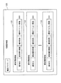
抽出装置50は、図18に示すように、制御部511と、表示部512と、入力部513と、情報記憶部514と、100個の通信部501、502、・・・、503から構成されている。
(1)表示部512
表示部512は、第1の実施の形態のメモリカードホルダー10が有する表示部102と同様の構成を有しており、液晶パネルとタッチパネルとからなる二重構造を有している。また、表示部102と同様の画面を表示する。
【0096】
(2)入力部513
入力部513は、第1の実施の形態のメモリカードホルダー10が有する入力部101と同様の構成を有している。
(3)情報記憶部514
情報記憶部514は、第1の実施の形態のメモリカードホルダー10が有する情報記憶部105と同様の構成を有している。
【0097】
また、情報記憶部514は、さらに、図19に一例として示すように、ID対応テーブル521を有している。
ID対応テーブル521は、通信部IDと媒体IDとマークとからなる組を100個記憶するための領域を備えている。
100個の組は、それぞれ100個の通信部501、502、・・・、503に対応している。
【0098】
通信部IDは、通信部501、502、・・・、503を一意に識別するための識別子である。具体的には、100個の通信部501、502、・・・、503には、通信部ID「1」、「2」、「3」、・・・、「100」が割り当てられている。100個の組は、あらかじめ、それぞれ通信部ID「1」、「2」、「3」、・・・、「100」を記憶している。
【0099】
媒体IDは、メモリカードを識別するための識別子である。
マークは、メモリカードと通信を行うことが選択された通信部を示すものである。つまり、マークを含む組に含まれる通信部IDにより示される通信部が選択されていることとなる。
(4)通信部501
通信部501は、アンテナ501a、LED501b、変復調部501c、駆動部501dを含んで構成されている。その他の通信部についても、同様の構成であるので、ここでは、説明を省略する。
【0100】
(アンテナ501a)
アンテナ501aは、ループコイル状に複数回巻かれた導線から構成されており、変復調部501cに接続されている。アンテナ501aは、送信用と受信用とを共用している。
アンテナ501aは、特定の方向に電波を放射する指向性アンテナである。変復調部501cから信号が乗せられた搬送波を受け取り、電波として空間に放射する。電波を放射できる範囲は、アンテナ501aの中央部から約30mm以内である。
【0101】
また、アンテナ501aは、電波を受信し、受信した電波を電力信号に変換して、電力信号を変復調部501cへ出力する。
(変復調部501c)
変復調部501cは、制御部511から信号(パルス状の信号波)を受け取る。前記信号を受け取ると、受け取った信号を変調信号として、変調信号に基づいて2.4GHzの搬送波の振幅を変化させ、振幅の変化した搬送波をアンテナ501aへ出力する。
【0102】
また、変復調部501cは、アンテナ501aから電力信号を受け取り、受け取った電力信号から2.4GHzの周波数を有する信号を選択し、選択した信号からパルス状の信号波を抽出し、抽出したパルス状の信号波を制御部511へ出力する。
(駆動部501d)
駆動部501dは、制御部511から発光又は消灯を示す指示信号を受け取る。前記指示信号を受け取ると、受け取った指示信号に基づいて、発光又は消灯を行うように、LED501bを駆動制御する。
【0103】
(LED501b)
LED501bは、発光ダイオード(light−emitting diode)であり、駆動部501dの制御の元に、発光、消灯を行う。
(5)制御部511
制御部511は、具体的には、マイクロプロセッサ、ROM、RAMなどから構成される。前記RAMには、コンピュータプログラムが記憶されている。前記マイクロプロセッサが、前記コンピュータプログラムに従って動作することにより、制御部511は、その機能を達成する。
【0104】
制御部511の動作については、後述する。
2.2 メモリカード60
メモリカード60a〜60eは、それぞれ同様の構成を有している。ここでは、メモリカード60として説明する。
メモリカード60は、図20に外観図を示すように、長さ30mm、幅30mm、厚さ0.5mmの板状に成形された樹脂内に、アンテナ601と回路部602とが、封入されて形成されている。メモリカード60の通信可能な距離は、約30mm程度以内であり、通信速度は、10〜20m秒/byteである。
【0105】
メモリカード60は、図21に示すように、アンテナ601と回路部602とから構成されており、回路部602は、変復調部603、電源部604、LED605、駆動部606、制御部607、駆動部608、駆動部609、スピーカ610、バイブレータ611及び情報記憶部612を含んで構成されている。
(1)アンテナ601
アンテナ601は、アンテナ501aと同様であり、ループコイル状に複数回巻かれた導線から構成されており、変復調部603及び電源部604に接続されている。アンテナ601は、送信用と受信用とを共用している。
【0106】
アンテナ601は、特定の方向に電波を放射する指向性アンテナである。変復調部603から信号が乗せられた搬送波を受け取り、電波として空間に放射する。電波を放射できる範囲は、アンテナ601の中央部から約30mm以内である。
また、アンテナ601は、電波を受信し、受信した電波を電力信号に変換して、電力信号を変復調部603へ出力する。また、電力信号を電源部604へ出力する。
【0107】
(2)電源部604
電源部604は、アンテナ601と接続され、アンテナ601から電力信号を受け取り、受け取った電力信号を電荷として蓄積する。また、メモリカード60の各構成部に電力を供給する。
(3)駆動部606
駆動部606は、制御部607から発光又は消灯を示す指示信号を受け取る。
前記指示信号を受け取ると、受け取った指示信号に基づいて、発光又は消灯を行うように、LED605を駆動制御する。
【0108】
(4)LED605
LED605は、発光ダイオード(light−emitting diode)であり、駆動部606の制御の元に、発光、消灯を行う。
(5)駆動部608
駆動部608は、制御部607から音声出力又は停止を示す指示信号を受け取る。前記指示信号を受け取ると、受け取った指示信号に基づいて、所定の周波数の音声信号をスピーカ610へ出力する。
【0109】
(6)スピーカ610
スピーカ610は、駆動部608から音声信号を受け取り、音声に変換して出力する。
(7)駆動部609
駆動部609は、制御部607から振動の開始又は停止を示す指示信号を受け取る。前記指示信号を受け取ると、受け取った指示信号に基づいて、振動の開始又は停止を行うように、バイブレータ611を駆動制御する。
【0110】
(8)バイブレータ611
バイブレータ611は、駆動部609の制御の元に、振動又はその停止を行う。
(9)情報記憶部612
情報記憶部612は、一般領域及び管理領域から構成されている。ここで、一般領域及び管理領域は、メモリカード21の情報記憶部203が有する一般領域221及び管理領域223が記憶している情報と同様の情報を記憶している。
【0111】
(10)制御部607
制御部607は、具体的には、マイクロプロセッサ、ROM、RAMなどから構成される。前記RAMには、コンピュータプログラムが記憶されている。前記マイクロプロセッサが、前記コンピュータプログラムに従って動作することにより、制御部607は、その機能を達成する。
【0112】
制御部607の動作については、後述する。
2.3 抽出装置50とメモリカード60との間の通信方式
抽出装置50の上にメモリカード60が置かれた場合における抽出装置50とメモリカード60との間の通信方式について説明する。
抽出装置50とメモリカード60との間の通信は、(a)電力の供給、(b)通信の確立及び(c)データの送受信の3個のフェーズにより行われる。以下において、各フェーズについて説明する。
【0113】
(a)電力の供給のフェーズ
抽出装置50の制御部511は、電力供給用の電波の出力を各通信部に対して指示し、各通信部は、電波を出力する。メモリカード60のアンテナ601は、電波を受信し、電源部604は、電荷を蓄積し、メモリカード60を構成する各構成要素に対して電力を供給する。
【0114】
なお、抽出装置50からメモリカード60への電力の供給は、このフェーズのみに限定されず、以下のフェーズにおいても、行われる。
(b)通信の確立のフェーズ
抽出装置50の各通信部は、同一の時間帯において、時分割された10個の通信チャネルと1個の制御チャネルとを介して、最大10枚の異なるメモリカードとの間で、通信を行う。各通信チャネル及び制御チャネルは、それぞれ上りチャネルと下りチャネルとを含んでいる。上りチャネルは、メモリカードから抽出装置50への情報の送信にのみに用いられ、下りチャネルは、抽出装置50からメモリカードへの情報の送信にのみ用いられる。なお、以下においては、簡略化のために、上りチャネルと下りチャネルとを特に区別しない。各上りチャネル及び各下りチャネルは、50m秒の時間幅を有する。
【0115】
抽出装置50の1個の通信部は、制御チャネルを介して、メモリカード60に対して、媒体IDを要求する。メモリカード60は、制御チャネルを介して、媒体IDの要求を受け取る。
次に、メモリカード60は、1から10までのいずれかの整数値からなる乱数を生成し、生成した乱数が示す1個の通信チャネルを選択する。なお、メモリカード60が情報記憶部612に記憶している媒体IDに、1から10までのいずれかの整数値を生成するハッシュ関数を施して、1個の整数値を生成し、生成した整数値を用いて、1個の通信チャネルを選択するとしてもよい。
【0116】
このように、メモリカードがランダムに生成した1から10までのいずれかの整数値を用いて、1個の通信チャネルを選択するので、複数のメモリカードが同一時間帯において、通信を始めた場合においても、用いる通信チャネルが衝突する可能性は低減される。また、複数のメモリカードにおいて、通信チャネルが衝突した場合には、各メモリカードは、それぞれ乱数により生成した時間経過後において、再度別の乱数を生成し、生成した乱数を用いて通信チャネルを選択する。
【0117】
次に、メモリカード60は、選択した通信チャネルを示すチャネル識別番号と、自身が記憶している媒体IDを、制御チャネルを介して、抽出装置50へ送信する。抽出装置は、制御チャネルを介して、チャネル識別番号と媒体IDとを受け取る。
なお、1個のメモリカードが、相互に近接して配置されている複数の通信部格納室の上部に置かれた場合、これらの通信部格納室内に設けられた複数の通信部が、前記メモリカードと通信を行うことになる。このとき、抽出装置50は、前記メモリカードと通信を行う1個の通信部を選択する。この選択方法の詳細については、後述する。
【0118】
このようにして、メモリカードと抽出装置50との間で用いる通信チャネルが確立される。
(c)データの送受信のフェーズ
メモリカード60と抽出装置50とは、前記チャネル識別番号により識別される通信チャネルを介して、データの送受信を行う。
【0119】
以上説明したように、時分割された10個の通信チャネルと1個の制御チャネルとを介して、メモリカードと抽出装置50との間で通信が行われる。従って、10枚以内の複数のメモリカードが重ねられた抽出装置50上に置かれた場合であっても、抽出装置50は、それぞれのメモリカードと通信を行うことができる。
【0120】
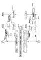
2.4 抽出装置50とメモリカード60との間の通信の動作
抽出装置50の上にメモリカード60が置かれた場合における抽出装置50とメモリカード60との間の通信の動作について、図22〜図24に示すフローチャートを用いて説明する。
抽出装置50の制御部511は、ステップS501から〜S509を、抽出装置50が有する通信部の数だけ、つまり100回繰り返す。この繰り返しにおいて、制御部511は、変数iを、1、2、3、・・・、100のように変化させる。
【0121】
制御部511は、変数iにより示される通信部に対して、媒体IDを要求する要求指示を出力し(ステップS502)、変数iにより示される通信部は、前記要求指示を電波で送信する(ステップS503)。メモリカード60の制御部607は、アンテナ601及び変復調部603を介して、前記要求指示を受け取り(ステップS503)、内部に記憶している媒体IDを読み出し(ステップS504)、駆動部606に対して、LED605を発光させるように制御し、LED605は、発光する(ステップS505)。次に、制御部607は、読み出した媒体IDを、変復調部603及びアンテナ601を介して、電波で送信する(ステップS506)。通信部は、媒体IDを受け取り、受け取った媒体IDを制御部511へ出力し(ステップS507)、制御部511は、変数iを通信部IDとして、通信部IDと受け取った媒体IDとの組をID対応テーブル521へ書き込む(ステップS508)。
【0122】
以上のようにして、各通信部と通信を行っているメモリカードを識別する媒体IDと、当該通信部を識別する通信部IDとの組が、ID対応テーブル521に記憶される。
次に、制御部511は、ID対応テーブル521から、媒体IDと組になった通信部IDを全て抽出し(ステップS510)、抽出した通信部IDを持つ通信部に対して、LEDを発光させるように発光信号を出力し(ステップS511)、対応する各通信部は、LEDを発光させる(ステップS513)。また、抽出した通信部IDを持たない通信部に対して、LEDを消灯させるように発光停止信号を出力し(ステップS512)、発光停止信号を受け取った通信部は、自身が有するLEDが発光していれば、LEDの発光を停止する(ステップS514)。
【0123】
以上のようにして、メモリカードが置かれた近辺にある通信部は、LEDを発光させ、その他の通信部は、LEDが発光していれば、消灯する。
次に、制御部511は、ID対応テーブル521に記憶されている各組を、媒体IDの順序で並び換え、並び換えられた組を含む一時テーブルを生成し(ステップS515)、同一媒体IDが含まれている1個以上の組の中から、1個を選択してマークを付す(ステップS516)。ここで、同一媒体IDが含まれている2個以上の組が存在するなら、1個のメモリカードが、相互に近接して配置されている複数の通信部格納室の上部に置かれていることとなる。これらの通信部格納室内に設けられた複数の通信部は、前記メモリカードと通信を行うことになる。この場合、これらの2個以上の各組は、前記1個のメモリカードの媒体IDと、各通信部の通信部IDとからなる。このとき、マークされた組に含まれる通信部IDにより識別される通信部が、前記メモリカードと通信を行う1個の通信部として選択される。
【0124】
次に、制御部511は、マークが付された組に含まれる通信部IDにより識別される通信部について、ステップS517からステップS524を繰り返す。
制御部511は、マークした通信部に対して情報要求を出力し(ステップS518)、当該通信部は、情報要求を電波により送信する(ステップS519)。メモリカードの制御部607は、アンテナ601及び変復調部603を介して、情報要求を受け取り(ステップS519)、情報要求された情報を情報記憶部612から読み出し(ステップS520)、読み出した情報を、変復調部603及びアンテナ601を介して送信し(ステップS521)、当該通信部は、前記情報を受け取り(ステップS521)、受け取った情報を制御部511へ出力する(ステップS522)。制御部511は、媒体IDと受け取った情報とを対応づけて情報記憶部514に書き込む(ステップS523)。
【0125】
以上のようにして、制御部511は、抽出装置50の上に置かれた全てのメモリカードから情報を読み出し、メモリカードを識別する媒体IDと読み出した情報とを対応付けて、情報記憶部514に書き込む。
次に、制御部511は、情報記憶部514に書き込まれた媒体IDと情報との組から、媒体IDのみを抽出して媒体IDリストを生成し、生成した媒体IDリストを表示部512へ出力し、表示部512は、媒体IDリストを表示する(ステップS525)。
【0126】
ここで、表示部512又は入力部513により、利用者の終了操作を受け付けると(ステップS526)、抽出装置50は、処理を終了し、電源をOFFとする。
表示部512又は入力部513により、利用者から媒体IDの選択を受け付けると(ステップS527)、表示部512又は入力部513は、選択を受け付けた媒体IDを制御部511へ出力し、制御部511は、媒体IDを受け取り、受け取った媒体IDに対応する情報を、情報記憶部514から読み出し、読み出した情報を表示部512へ出力し、表示部512は、情報を表示する(ステップS528)。
【0127】
また、制御部511は、対応する通信部へLEDを点滅する指示を出力し、また、対応するメモリカードに対するLEDの点滅の指示を対応する通信部へ出力する(ステップS529)。通信部は、LEDを点滅する(ステップS531)。また、通信部は、LEDの点滅の指示をメモリカードへ出力し(ステップS530)。メモリカードは、LEDを点滅し、バイブレータを振動させ、スピーカから音声を出力させる(ステップS532)。
【0128】
以上のようにして、利用者により選択されたメモリカードに記憶されている情報を表示部512に表示させ、前記選択されたメモリカードのLEDを点滅させ、バイブレータを振動させ、スピーカから音声を出力させ、前記メモリカードが置かれた近辺の抽出装置50のLEDを点滅させる。こうして、利用者は、表示された情報と、メモリカードとの対応付けを知ることができる。
【0129】
2.5 その他の変形例
以上、抽出装置50について説明してきたが、本発明は、上記の実施の形態に限定されないのはもちろんである。以下のような場合も本発明に含まれる。
(1)抽出装置50は、第1の実施の形態において説明したように、利用者から所望するメモリカードに関する検索条件の入力を受け付け、受け付けた検索条件を満たすメモリカードを、抽出装置50の上に置かれた複数のメモリカードから特定し、特定したメモリカードが有するLEDを発光させるとともに、特定したメモリカードの近辺において、抽出装置50が備えるLEDを発光させるとしてもよい。
【0130】
(2)上述した抽出装置50において、直交する仕切り板により区切られた通信部格納室内に、各通信部が設けられているとしているが、以下のようにしてもよい。
通信部格納室は、図25(a)に示すように、等間隔に平行するように設けられた複数枚の仕切り板と、前記仕切り板にそれぞれ120度の角度をなし、それぞれが等間隔に平行するように設けられた複数枚の仕切り板とにより、平行四辺形状に区切られることにより形成されているとしてもよい。このようにして、形成された通信部格納室の中央部に、アンテナとLEDとが設置される。図25(a)において、仕切り板が設置されている位置を破線により示している。なお、前記の角度は、120度には限定されない。他の角度であってもよい。
【0131】
また、通信部格納室は、図25(b)に示すように、等間隔に平行するように設けられた複数枚の仕切り板と、前記仕切り板にそれぞれ120度の角度をなし、それぞれが等間隔に平行するように設けられた複数枚の仕切り板と、さらに、60度の角度をなし、それぞれが等間隔に平行するように設けられた複数枚の仕切り板とにより、正三角形状に区切られることにより形成されているとしてもよい。このようにして、形成された通信部格納室の中央部に、アンテナとLEDとが設置される。図25(b)において、仕切り板が設置されている位置を破線により示している。
【0132】
また、通信部格納室は、図25(c)に示すように、ハニカム形状に設けられた複数の仕切り板により、六角形状に区切られることにより形成されているとしてもよい。このようにして、形成された通信部格納室の中央部に、アンテナとLEDとが設置される。図25(c)において、仕切り板が設置されている位置を破線により示している。
【0133】
(3)上述した抽出装置50は、その上面において、その置かれる位置が限定されることなく、利用者により自由に配されたメモリカードから情報を読み出すとしているが、次に示すようにしてもよい。
抽出装置70は、図26に示すように、その上面において、3行×3列のマトリックスの各要素に対応する位置に、9個の凹部711〜719が設けられており、各凹部は、メモリカードを収容し、メモリカードの形状に相似する凹形状に形成されている。利用者は、各凹部にメモリカードを収納する。また、抽出装置70の上面部において、上記凹部を除く凸状部に、9個の凹部711〜719に対応して、それぞれ9個のLED711a〜719aが設けられている。
【0134】
さらに、図27に示すように、凹部714の側面721と、側面721に対向する位置にある側面722のそれぞれにおいて、透孔731、732が開設されており、側面721内部に発光素子714bを備え、側面722内部に受光素子714cを備えている。発光素子714bは、透孔731及び732を通して、受光素子714cに対して光を照射する。凹部714の底面内部には、コイル状のアンテナを含む通信部が設けられている。
【0135】
ここで、図27は、凹部714の底面と抽出装置の上面との間にあり、凹部714の底面に平行な切断平面により抽出装置70を切断して得られる断面図である。
他の凹部についても、凹部714と同様である。また、その他、抽出装置70は、抽出装置50と同様の構成を有している。
【0136】
利用者により、メモリカードが凹部714に収納されると、受光素子714cは、発光素子714bから照射される光が遮断されたことを検出し、遮断を示す信号を制御部へ出力する。制御部は、前記信号を受け取ると、凹部714にメモリカードが収納されたと認識し、凹部714の底面内部に設けられた通信部に対して、メモリカードとの通信を行うように制御する。
【0137】
このようにして、抽出装置70は、凹部に収納されたメモリカードを検出し、収納されたメモリカードと凹部底面内部に設けられた通信部によりメモリカードとの通信を行うことにより、メモリカードが情報を読み出し、読み出した情報を記憶し、また表示する。
(4)次に示すように構成してもよい。
【0138】
メモリカード60の表面にバーコードが印刷されている。このバーコードは、メモリカードが記憶している媒体IDがバーコード化されて形成されたものである。
バーコードリーダ装置は、前記バーコードを光学的に読み取り、読み取ったバーコードを、元の媒体IDに変換するバーコードリーダ部と、変換されて生成された媒体IDを用いて、前記媒体IDを記憶しているメモリカードを特定し、特定されたメモリカードから電波により情報を読み出す通信部と、メモリカードから読み出した情報を表示する表示部を備えている。
【0139】
(5)メモリカードから取得して表示される情報には、媒体ID、タイトル情報、メモリカードの残り記憶容量などが含まれる。
(6)収納ケースを兼ねている装置に電子カードをいれておき、前記装置は、利用者からメニューにより「容量の大きいカード」という検索条件の入力を受け付け、前記検索条件を満たす電子カードを抽出し、抽出した電子カードを発光させるようにしてもよい。
【0140】
3.その他の変形例
なお、本発明を上記の実施の形態に基づいて説明してきたが、本発明は、上記の実施の形態に限定されないのはもちろんである。以下のような場合も本発明に含まれる。
(1)メモリカードホルダーは、次に示すように構成してもよい。
【0141】
メモリカードホルダー85は、図28にその外観図を示すように、最大5枚分のメモリカードを保持するための保持装置である。
メモリカードホルダー85は、USBケーブル811を介して、パーソナルコンピュータ80と接続されることによって、利用者に使用される。
メモリカードホルダー85は、その側面部に5個のカード接続部851〜855を備えており、各カード接続部に1枚のメモリカードが挿入されて、メモリカードとメモリカードホルダー85とが電気的に接続される。この図において、カード接続部851〜852には、メモリカード861〜862がそれぞれ挿入されて接続されている。カード接続部853〜855には、メモリカードは挿入されていない。
【0142】
パーソナルコンピュータ80は、マイクロプロセッサ、ROM、RAM、ハードディスクユニット、液晶ディスプレィ部802、キーボード部801などから構成されるコンピュータシステムである。前記RAM又は前記ハードディスクユニットには、コンピュータプログラムが記憶されている。前記マイクロプロセッサが、前記コンピュータプログラムに従って動作することにより、パーソナルコンピュータ80は、その機能を達成する。
【0143】
メモリカードホルダー85は、図1に示すメモリカードホルダー10のカード保持部10cに相当し、USBケーブル811は、接続部10bに相当し、パーソナルコンピュータ80は、入力表示部10aに相当している。
USBケーブル811により接続されたメモリカードホルダー85及びパーソナルコンピュータ80は、図1に示すメモリカードホルダー10と同様に動作する。
【0144】
(2)メモリカードホルダーは、次に示すように構成してもよい。
パーソナルコンピュータ90は、図29にその外観図を示すように、パーソナルコンピュータ80と同様のコンピュータシステムである。マイクロプロセッサが、コンピュータプログラムに従って動作することにより、パーソナルコンピュータ90は、その機能を達成する。
【0145】
パーソナルコンピュータ90は、その側面部に5個のカード接続部911〜915を備えており、各カード接続部に1枚のメモリカードが挿入されて、メモリカードとパーソナルコンピュータ90とが電気的に接続される。このように、パーソナルコンピュータ90は、最大5枚分のメモリカードを保持するための保持装置も兼ねている。
【0146】
この図において、カード接続部914〜915には、メモリカード924〜925がそれぞれ挿入されて接続されている。カード接続部911〜913には、メモリカードは挿入されていない。
パーソナルコンピュータ90は、図1に示すメモリカードホルダー10と同様に動作する。
【0147】
(3)本発明は、上記に示す方法であるとしてもよい。また、これらの方法をコンピュータにより実現するコンピュータプログラムであるとしてもよいし、前記コンピュータプログラムからなるデジタル信号であるとしてもよい。
また、本発明は、前記コンピュータプログラム又は前記デジタル信号をコンピュータ読み取り可能な記録媒体、例えば、フレキシブルディスク、ハードディスク、CD―ROM、MO、DVD、DVD−ROM、DVD−RAM、BD(Blu−ray Disc)、半導体メモリなど、に記録したものとしてもよい。また、これらの記録媒体に記録されている前記コンピュータプログラム又は前記デジタル信号であるとしてもよい。
【0148】
また、本発明は、前記コンピュータプログラム又は前記デジタル信号を、電気通信回線、無線又は有線通信回線、インターネットを代表とするネットワーク、データ放送等を経由して伝送するものとしてもよい。
また、本発明は、マイクロプロセッサとメモリとを備えたコンピュータシステムであって、前記メモリは、上記コンピュータプログラムを記憶しており、前記マイクロプロセッサは、前記コンピュータプログラムに従って動作するとしてもよい。
【0149】
また、前記プログラム又は前記デジタル信号を前記記録媒体に記録して移送することにより、又は前記プログラム又は前記デジタル信号を前記ネットワーク等を経由して移送することにより、独立した他のコンピュータシステムにより実施するとしてもよい。
(4)上記実施の形態、上記実施の形態の一部及び上記変形例をそれぞれ組み合わせるとしてもよい。
【0150】
【発明の効果】
以上説明したように、本発明は、記録媒体を保持する記録媒体ホルダーであって、電気的な接続により読み書き可能であり、デジタル情報、又はデジタル情報及びその内容を示す情報を記録している1個以上の記録媒体を、電気的に接続された状態で保持する保持手段と、前記保持手段により保持及び接続されている前記記録媒体の中から1個の記録媒体を選択する選択手段と、選択された記録媒体に記録されているデジタル情報へのアクセスが許可されているか否かを判定する判定手段と、前記判定手段がアクセス可と判定した場合に、選択された前記記録媒体に記録されているデジタル情報又はその内容を示す情報を表示する表示手段とを備える。
【0151】
この構成によると、アクセスが可と判定された場合に、記録媒体に記録されてい情報などを表示するので、記録媒体に秘密の情報が記録されている場合に、前記記録媒体を安全に扱うことができる。
ここで、前記判定手段は、利用者から利用者パスワードの入力を受け付ける入力部と、あらかじめ機器パスワードを保持しているパスワード保持部と、入力を受け付けた前記利用者パスワードと、保持している前記機器パスワードとを比較し、一致する場合に、アクセス可と判定するパスワード判定部とを含む。
【0152】
この構成によると、記録媒体ホルダーに登録されている機器パスワードと、入力を受け付けた利用者パスワードとを照合して、アクセスが可か否かを判定するので、機器パスワードを知っている正当な利用者にのみアクセスを許可することができる。
ここで、前記記録媒体は、あらかじめ媒体パスワードを保持しているパスワード保持手段を備え、前記判定手段は、利用者から利用者パスワードの入力を受け付ける入力部と、入力を受け付けた前記利用者パスワードと、保持している前記媒体パスワードとを比較し、一致する場合に、アクセス可と判定するパスワード判定部とを含む。
【0153】
この構成によると、記録媒体に登録されている媒体パスワードと、入力を受け付けた利用者パスワードとを照合して、アクセスが可か否かを判定するので、記録媒体に登録されている媒体パスワードを知っている正当な利用者にのみアクセスを許可することができる。
ここで、前記表示手段は、さらに、前記保持手段により保持及び接続されている前記記録媒体に対応するアイコンを表示し、前記選択手段は、前記表示手段により表示されたアイコンのうち、利用者のクリックによりいずれか1個のアイコンの選択を受け付け、選択を受け付けたアイコンに対応する記録媒体を選択する。
【0154】
この構成によると、アイコンを選択することにより、記録媒体を選択することができるので、記録媒体の選択が視覚的に容易にできる。
ここで、前記記録媒体ホルダーは、さらに、情報を一時的に保持するための領域を備える記録手段を含み、前記選択手段は、さらに、記録媒体を初めて選択した場合に、選択した記録媒体に記録されているデジタル情報、又はデジタル情報及びその内容を示す情報を前記記録手段に記録し、前記選択手段により前記記録媒体を2回目以降選択した場合に、前記表示手段は、選択された前記記録媒体に記録されているデジタル情報又はその内容を示す情報の表示に代えて、前記記録手段に記録されている前記デジタル情報又はその内容を示す情報を表示する。
【0155】
この構成によると、2回目以降に記録媒体を選択した場合に内部に記憶している情報を表示するので、操作から表示までの処理時間を短縮することができる。
ここで、前記記録媒体ホルダーは、さらに、文字の入力を受け付ける文字入力手段と、前記文字入力手段により入力を受け付けた文字に基づいて、前記保持手段に保持及び接続されている前記記録媒体に記録されているデジタル情報を検索し、前記入力された文字に一致するデジタル情報が記録された記録媒体を利用者に通知する検索手段とを含む。
【0156】
この構成によると、入力を受け付けた文字に一致する情報を記録している記録媒体を利用者に通知するので、利用者は、所望の記録媒体を容易に見つけ出すことができる。
また、本発明は、電波を用いて非接触に読み書き可能な1個以上の記録媒体と、前記記録媒体を保持する保持装置とから構成される電子カードシステムであって、前記記録媒体は、デジタル情報を記憶している情報記憶手段と、電波を用いて前記デジタル情報を送信する送受信手段とを含み、前記保持装置は、保持手段と制御手段と表示手段とを備え、前記保持手段は、媒体保持平面と、複数組の送受信部及び発光部とを備え、前記媒体保持平面は、前記同数の区画に区分され、各組の送受信部及び発光部は、各区画に対向して設置され、各送受信部は、対向する当該区画の少なくとも一部を覆うように、記録媒体が前記媒体保持平面上に保持されている場合において、電波を用いて当該記録媒体からデジタル情報を読み出し、読み出したデジタル情報を制御部へ出力し、各発光部は、制御手段の制御により発光し、前記制御手段は、前記デジタル情報を受け取り、受け取ったデジタル情報を基にして表示情報を生成して出力し、前記デジタル情報の出力元の前記送受信部に対応する前記発光部に対して発光するように制御し、前記表示手段は、表示情報を受け取り、受け取った表示情報を表示する。
【0157】
この構成によると、利用者が情報記録媒体を抽出装置に挿入などをするなどの手間をかけることなく、所望の情報記録媒体を選択することができる。
ここで、前記記録媒体は、さらに、発光、振動又は音声を出力する出力手段を備え、前記制御手段は、さらに、前記デジタル情報を受け取ると、電波を用いて前記送受信部及び前記記録媒体が有する前記送受信手段を介して、前記記録媒体が有する前記出力手段に対して、発光、振動又は音声を出力するように制御する。
【0158】
この構成によると、所望の情報記録媒体が、発光、振動又は音声を出力するので、所望の情報記録媒体を容易に識別することができる。
ここで、前記制御手段は、さらに、利用者から検索情報の入力を受け付け、区画毎に受け取ったデジタル情報から、前記入力を受け付けた検索情報に合致するデジタル情報を特定し、特定されたデジタル情報を記憶している記録媒体を保持する区画に対向する発光部に対して発光するように制御する。
【0159】
この構成によると、所望の情報記録媒体が置かれた位置において発光するので、利用者は、所望の情報記録媒体を容易に識別することができる。
【図面の簡単な説明】
【図1】メモリカードホルダー10の外観図を示す。
【図2】メモリカードホルダー10の構成を示すブロック図である。
【図3】情報記憶部105に記憶されている情報の一例を示す。
【図4】表示部102に表示される画面161の構成を示す。
【図5】スロットアイコンの形状をその意味とともに示す。
【図6】表示部102に表示される画面171の構成を示す。
【図7】メモリカード21の構成を示すブロック図である。
【図8】情報記憶部203に記憶されている情報の一例を示す。
【図9】メモリカードホルダー10全体の概要動作を示すフローチャートである。
【図10】メモリカードホルダー10の電源ON直後の動作を示すフローチャートである。
【図11】利用者によりスロットアイコンが選択された場合における、スロットの処理を示すフローチャートである。図12へ続く。
【図12】利用者によりスロットアイコンが選択された場合における、スロットの処理を示すフローチャートである。図11から続く。
【図13】メモリカードホルダー10と、認証タイプのメモリカードとの間で行われる相互認証の動作を示すフローチャートである。
【図14】パスワードの確認動作を示すフローチャートである。
【図15】検索処理の動作を示すフローチャートである。
【図16】メモリカードホルダー100bの外観図を示す。
【図17】抽出装置50の分解図を示している。
【図18】抽出装置50の構成を示すブロック図である。
【図19】情報記憶部514が有しているID対応テーブル521のデータ構造を示す。
【図20】メモリカード60の外観図を示す。アンテナ601と回路部602とは、メモリカード60の内部に封入されているので、実際に、外部から見ることはできない。この図面では、容易に理解できるように、アンテナ601と回路部602とを描いている。
【図21】メモリカード60の構成を示すブロック図である。
【図22】抽出装置50の上にメモリカード60が置かれた場合における抽出装置50とメモリカード60との間の通信の動作を示すフローチャートである。図23へ続く。
【図23】抽出装置50の上にメモリカード60が置かれた場合における抽出装置50とメモリカード60との間の通信の動作を示すフローチャートである。図24へ続く。
【図24】抽出装置50の上にメモリカード60が置かれた場合における抽出装置50とメモリカード60との間の通信の動作を示すフローチャートである。図23から続く。
【図25】通信部格納室の形状を示す。
(a)平行四辺形型の形状である。
(b)正三角形型の形状である。
(c)ハニカム型の形状である。
【図26】抽出装置70の外観図を示す。
【図27】抽出装置70のA−A’断面図の一部分を示す。
【図28】パーソナルコンピュータ80及びメモリカードホルダー85の外観図を示す。
【図29】パーソナルコンピュータ90の外観図を示す。
【符号の説明】
10 メモリカードホルダー
10a 入力表示部
10b 接続部
10c カード保持部
21〜25 メモリカード
30 操作ペン
50 抽出装置
50a 蓋部
50b 本体部
60a〜60e メモリカード
70 抽出装置
80 パーソナルコンピュータ
85 メモリカードホルダー
90 パーソナルコンピュータ[0001]
BACKGROUND OF THE INVENTION
The present invention relates to a holding device that holds an information recording medium for storing information.
[0002]
[Prior art]
Conventionally, a recording medium such as a flexible disk (FD) has been used to store digital information.
A sticker on which information such as a title and an index indicating the contents of the stored digital information is written is attached to the outer surface of the FD so that the user can easily know the digital information stored in the FD. . The user finds out the necessary FD by looking at the sticker attached.
[0003]
However, as the recording medium is further reduced in size, the sticker to be attached to the recording medium is further reduced, and there is a problem that sufficient information cannot be written on the seal or there is no space for attaching the sticker on the recording medium. is there.
In order to solve such problems, Japanese Patent Laid-Open No. 2-115996 discloses a technology for providing a display unit for displaying data contents on the surface of a PC card and identifying the card based on information displayed on the display unit. Has been.
[0004]
Japanese Laid-Open Patent Publication No. 4-367090 discloses a technique for providing a liquid crystal display unit in a memory card and displaying stored data such as titles on the liquid crystal display unit. Both of these technologies are replaced with stickers by displaying the contents on the card itself.
Japanese Patent Laid-Open No. 2001-101356 discloses a technique for providing an LCD on a PC card adapter and displaying additional information such as an image stored in the card and a shooting date and time on the LCD.
[0005]
Further, according to Japanese Patent Laid-Open No. 2000-29998, a recording / reproducing apparatus capable of mounting a plurality of memory cards is disclosed, and the recording / reproducing apparatus includes a display unit for displaying the contents of an operating card. . Also, according to Japanese Patent Laid-Open No. 2000-32582, a headphone device is disclosed that has a changer function in the headband unit to store a plurality of memory cards, and has a means for selecting and playing back the memory cards. Yes. These techniques display contents on a holder for holding a recording medium.
[0006]
[Patent Document 1]
Japanese Patent Laid-Open No. 2-115996
[0007]
[Patent Document 2]
JP-A-4-367090
[0008]
[Patent Document 3]
JP 2001-101356 A
[0009]
[Patent Document 4]
JP 2000-29998 A
[0010]
[Patent Document 5]
JP 2000-32582 A
[0011]
[Problems to be solved by the invention]
However, according to the above prior art, information indicating the contents of the recording medium can be displayed on the recording medium, the adapter, the reproduction device, etc., but the problem in the case of sticking the seal to the recording medium is solved. When the number of recording media managed by the user increases, there is a problem that it is difficult to immediately find a necessary recording medium.
[0012]
The present invention provides a recording medium holder and an electronic card system that can solve the above problems and can more easily find a recording medium required by a user regardless of the number of recording media managed by the user. The purpose is to provide.
[0013]
[Means for Solving the Problems]
The present invention is a recording medium holder capable of efficiently and safely managing a plurality of recording media, and even when the information stored in the recording medium is confidential information, the information can be safely stored. It is intended to be able to present. When the user owns a plurality of recording media, the recording medium holder includes means for displaying the contents of the recording medium, and a recording medium so that the necessary recording medium can be searched immediately. Means for displaying the content of the recording medium only when the display of the content of the recording medium is permitted when the content is confidential information.
[0014]
The recording medium holder is
(1) a recording medium storage unit for storing a plurality of recording media;
(2) a liquid crystal display unit for displaying each of a plurality of recording media stored in the recording medium storage unit with an icon;
(3) Click on the icon displayed on the LCD with a pen, etc.
When clicked for the first time, the ID information, title information, index information, etc. of the recording medium corresponding to the icon are read from the recording medium and displayed on the liquid crystal display unit.
When clicked for the second time and thereafter, the information display unit reads out the ID information, title information, index information, etc. of the card corresponding to the icon from the storage unit and displays it on the liquid crystal display unit.
[0015]
The present invention also includes a card and an extraction device that allow the user to check the contents of the card without inserting the card into the device and extract a specific card from a plurality of cards. Electronic card system. According to the prior art, when the number of cards to be managed increases, it is difficult to find a necessary card from among them. For example, the available capacity of a card cannot be known without inserting the card into a device such as a personal computer, and it takes time to identify the card with the smallest available capacity from a plurality of cards. Thus, according to the prior art, it is difficult to immediately search for a card containing specific data or a card with a large free space. The present invention solves such a problem.
[0016]
The present invention can supply power to an electronic card that can receive power supply without contacting other devices and has a rewritable memory function, and can hold power inside the electronic card. In the electronic card system including the extraction device, the electronic card can alert the user with a message transmitted from the extraction device.
[0017]
Specifically, the electronic card receives data transmitted from the extraction device. Next, the electronic card returns data held by the electronic card itself, for example, the electronic card name, remaining capacity, owner name, etc. to the extraction device. Based on the extraction criteria selected by the user, the extraction device identifies the electronic card. Next, the extraction device transmits an extraction message together with the card ID to the specified electronic card. Next, the electronic card that has received the extraction message notifies the user of the extraction using its own functions such as light emission, vibration, and voice output.
[0018]
In addition, the present invention can supply power to an electronic card having a rewritable memory function that can be supplied with power without contacting other devices, and holding the power inside. An electronic card system comprising an extraction device capable of holding an information display unit, wherein information of the electronic card, for example, card ID, title information, remaining capacity, etc. is displayed on the information display unit.
[0019]
Here, the electronic card receives the data transmitted from the extraction device, returns the information of the electronic card to the extraction device, and the extraction device displays the information of the electronic card on the information display unit.
[0020]
DETAILED DESCRIPTION OF THE INVENTION
1. First embodiment
A
1.1
The
[0021]
Normally, as shown in FIG. 1, the
The
[0022]
The
As shown in a block diagram in FIG. 2, the
[0023]
Specifically, the
[0024]
(1)
As illustrated in FIG. 3 as an example, the
The device password is a password uniquely set for the
[0025]
Here, the device password is used by only a user who knows the device password (usually the owner of the memory card holder) to permit the use of the memory card holder. A third party who does not know the device password cannot illegally use the memory card holder.
The
[0026]
As shown in this figure, the
The same applies to the
(2)
The
[0027]
In addition, when a part of the screen is pressed by the user using the
(Screen 161)
The
[0028]
The
Various slot icons that may be displayed on the
[0029]
The slot icon I101 shown in this figure indicates that no memory card is inserted into the corresponding card connection unit. The slot icon I102 indicates that a memory card is inserted into the corresponding card connection unit and is electrically connected.
Further, the slot icon I103 indicates that the authentication has failed in the mutual device authentication between the memory card and the
[0030]
Further, when the slot icon I101 and the slot icon I102 are repeatedly displayed in a short time, the slot icon blinks. The meaning of the blinking of the slot icon will be described later.
Each of the slot icons I104 to I106 is a medium icon stored in advance in a memory card that is inserted and connected to a corresponding card connection unit. The slot icons I104 to I106 are displayed only for a special memory card in which the memory card itself stores the slot icon. The slot icon I102 is a standard icon displayed when the memory card inserted and connected to the corresponding card connection unit does not store the medium icon by itself.
[0031]
In the first embodiment, the case where icons are stored in advance in the memory card is described, but the present invention is not limited to this. For example, the memory card holder stores a typical card type dedicated icon in advance, and when the card is connected to the connection unit, the dedicated icon for the card is displayed instead of the standard icon. You may do it.
[0032]
The medium
[0033]
The
The
(Screen 171)
As shown in FIG. 6 as an example, the
[0034]
[0035]
As shown in FIG. 6, the search
The search item selection unit includes a search
[0036]
The search keyword input unit is an area that accepts input of one or more character strings to be searched from the user.
The search method selection unit accepts an input of “AND condition” or “OR condition” by the user. The “AND condition” or “OR condition” indicates a condition when two or more character strings are received in the search keyword input unit.
[0037]
Specifically, when “medium ID” is selected in the search item selection unit, “SD0001 SD0002” is input in the search keyword input unit, and “OR” is selected in the search method selection unit,
It is assumed that the search condition “search ID =“ SD0001 ”OR search ID =“ SD0002 ”” is designated.
[0038]
The search
For example, when search conditions are selected and input in the search
"Search conditions selected and input by the search
AND It is assumed that “search condition selected and input by the search
[0039]
The same applies when search conditions are selected and input in the search
The
The
[0040]
The number-of-
(3)
The
[0041]
Since the
(4)
The
[0042]
(5)
The
[0043]
The
(6)
The
[0044]
1.2
As shown in FIG. 7, the
(1) Input /
When the
[0045]
The input /
[0046]
(2)
The
(3)
As shown in FIG. 8, the
[0047]
(General area 221)
The
As shown in FIG. 8 as an example, the
[0048]
Content consists of music, video, and other digital information. The encrypted content is obtained by encrypting content composed of music, video, and other digital information using a predetermined encryption algorithm.
The content ID is an identifier for identifying the content. The content title is information indicating the content. The information type indicates the type of content. For example, the distinction between music information, video information, character information, and the like is shown. The creation date indicates the date and time when the content was generated. The update date indicates the date and time when the content was updated.
[0049]
(Secure area 222)
The
As an example, the
[0050]
(Management area 223)
The
The
[0051]
The medium password is for restricting access to the
The medium ID is an identification number unique to the
[0052]
The manufacturer name is a name indicating the manufacturer of the
[0053]
In the first embodiment, the case where the information storage unit includes a general area, a secure area, and a management area is described, but the present invention is not limited to this. For example, the information storage unit may include a general area and a secure area. In this case, the information stored in the management information is recorded in the secure area.
1.3 Memory cards 22-25
The
[0054]
The information storage unit included in the
The
[0055]
1.4 Operation of
The operation of the
(1) Overall operation of the
Here, the overall operation of the
[0056]
When the user turns on the power, the
Next, the
Next, the
[0057]
When the search icon is indicated (step S103), the
When other icons are indicated (step S103), the
[0058]
When the end icon is indicated (step S103), the
(2) Operation immediately after power ON
Here, the operation immediately after the
[0059]
When the user turns on the power, the process from step S111 to step S121 is repeated for each of the five slots into which the memory cards are inserted, that is, the
The card connection unit determines whether or not a memory card is inserted and connected to the card connection unit, and if not inserted (step S112), the display position of the slot icon corresponding to the card connection unit A slot icon indicating that a memory card is not inserted is displayed (step S123), and all information written in the medium information area corresponding to the card connection unit is erased (step S124). The process relating to the part is terminated.
[0060]
When a memory card is inserted and connected to the card connection unit (step S112), the
[0061]
When the
[0062]
When it is determined that it is not the password type (step S117), the
[0063]
When the
When the authentication failure information indicating the authentication failure is received from the authentication unit 103 (step S116), the
[0064]
When the
As described above, it is determined whether or not a memory card is inserted into the card connection section. When a memory card is inserted and connected, a slot icon indicating insertion is displayed and connected. If there is no slot icon, a slot icon indicating non-insertion is displayed.
[0065]
(3) Slot processing
Here, processing of a slot when a slot icon is selected by the user will be described using the flowcharts shown in FIGS. The operation described below is the details of step S104 in the flowchart of FIG.
[0066]
The
When determining that the memory card is connected (step S142), the
[0067]
When the
[0068]
When the
When determining that both the medium IDs match (step S155), the
When determining that the two medium IDs do not match (step S155), the
[0069]
Next, the
[0070]
If the passwords do not match (step S148), the
Upon receiving authentication failure information indicating authentication failure from the authentication unit 103 (step S146), the
[0071]
When determining that the memory card is not connected (step S142), the
[0072]
(4) Mutual authentication operation
Here, the mutual authentication operation performed between the
[0073]
The
[0074]
When the authentication fails (step S172 or step S174), the
(5) Password confirmation operation
Here, the password confirmation operation will be described with reference to the flowchart shown in FIG. The operation described below is the details of step S147 in the flowchart of FIG.
[0075]
Using the acquired medium type information, the
When the password is not checked (step S191), the
[0076]
In the case of the type for performing confirmation by the medium password (step S191), the
[0077]
When it is determined that they match (step S194), the
When determining that they do not match (step S194), the
In the case of a type that performs confirmation using a device password (step S191), the
[0078]
When determining that they match (step S197), the
When determining that they do not match (step S197), the
(6) Search processing operation
Here, the operation of the search process will be described using the flowchart shown in FIG. The operation described below is the details of step S105 in the flowchart of FIG.
[0079]
The
Next, the
[0080]
In other cases (step S212), the
[0081]
Next, the
Next, the
[0082]
Here, the slot processing in step S220 is the same processing as step S104 in the flowchart of FIG.
(7) Processing when removing the memory card
The memory card can be taken out from the memory card holder by the following procedure.
[0083]
When taking out the memory card from the memory card holder, it can be taken out by an operation using an icon to be described later or by pressing a memory card take-out switch. Here, the memory card removal switch is the same as the mechanism for removing the PC card from a normal notebook personal computer.
Further, the operation using icons is as follows.
[0084]
An icon indicating a trash can is displayed on the liquid crystal display unit. By dragging and dropping a card icon to the trash box, a memory card corresponding to the icon can be taken out. This is also similar to a mechanism for taking out a PC card from a normal notebook personal computer.
When removing a memory card, if the memory card is a type that requires the user to enter a password, the memory card removal process is performed regardless of whether the type uses a media password or the type that uses a device password. Prior to this, the memory card holder requests input of a password, and if the input password does not match the medium password or the device password, the memory card holder is locked so that the memory card cannot be removed. This is to prevent a third party from taking out the memory card illegally when the memory card holder is lost.
[0085]
1.5 Other variations
The
(1)
The
[0086]
As shown in the external view of FIG. 16, the
Further, in the region from the
[0087]
The five
(2) The
[0088]
(3) Although the independent type memory card holder has been described in the first embodiment and the other modification (1), the present invention is not limited to this. For example, the additional function of the mobile phone may be of a composite type having the function provided in the memory card holder described in the first embodiment.
(4) In the first embodiment, the case where authentication by password is used is shown, but the present invention is not limited to this. For example, instead of authentication using a password, authentication using biological characteristic information of a user such as a fingerprint or an iris can be used. Further, an authentication device can be used instead of the authentication using the device password. In this case, the authentication device is attached to the memory card holder, and when the authentication device is attached, the memory card holder can be used for the first time.
[0089]
2. Second embodiment
An
2.1
The
[0090]
FIG. 17 shows an exploded view of the
The
[0091]
100 f of communication
[0092]
The communication
[0093]
A
The
[0094]
A plurality of
[0095]
As shown in FIG. 18, the
(1)
The
[0096]
(2)
The
(3)
The
[0097]
Further, the
The ID correspondence table 521 includes an area for storing 100 sets of communication unit IDs, medium IDs, and marks.
100 sets correspond to 100
[0098]
The communication unit ID is an identifier for uniquely identifying the
[0099]
The medium ID is an identifier for identifying the memory card.
The mark indicates a communication unit selected to communicate with the memory card. That is, the communication unit indicated by the communication unit ID included in the set including the mark is selected.
(4)
The
[0100]
(
The
The
[0101]
The
(
The
[0102]
Further, the
(Driver 501d)
The driving unit 501d receives an instruction signal indicating light emission or light extinction from the
[0103]
(LED501b)
The
(5)
Specifically, the
[0104]
The operation of the
2.2
The
As shown in the external view of FIG. 20, the
[0105]
As shown in FIG. 21, the
(1)
The
[0106]
The
Further, the
[0107]
(2)
The
(3)
The
When the instruction signal is received, the
[0108]
(4) LED605
The
(5)
The
[0109]
(6)
The
(7)
The
[0110]
(8)
The
(9)
The
[0111]
(10)
Specifically, the
[0112]
The operation of the
2.3 Communication method between
A communication method between the
Communication between the
[0113]
(A) Power supply phase
The
[0114]
The supply of power from the
(B) Communication establishment phase
Each communication unit of the
[0115]
One communication unit of the
Next, the
[0116]
As described above, since one communication channel is selected using any integer value from 1 to 10 randomly generated by the memory card, a plurality of memory cards start communication in the same time zone. The possibility of collision of communication channels to be used is also reduced. In addition, when communication channels collide in multiple memory cards, each memory card generates another random number after the time generated by each random number, and selects the communication channel using the generated random number. To do.
[0117]
Next, the
When one memory card is placed on top of a plurality of communication unit storage chambers arranged close to each other, a plurality of communication units provided in these communication unit storage chambers are connected to the memory. Communicate with the card. At this time, the
[0118]
In this way, a communication channel used between the memory card and the
(C) Data transmission / reception phase
The
[0119]
As described above, communication is performed between the memory card and the
[0120]
2.4 Operation of communication between
The communication operation between the
The
[0121]
The
[0122]
As described above, a set of a medium ID that identifies a memory card that communicates with each communication unit and a communication unit ID that identifies the communication unit is stored in the ID correspondence table 521.
Next, the
[0123]
As described above, the communication unit in the vicinity where the memory card is placed causes the LED to emit light, and the other communication units are turned off if the LED emits light.
Next, the
[0124]
Next, the
The
[0125]
As described above, the
Next, the
[0126]
Here, when a user's end operation is received by the
When the selection of the medium ID is received from the user by the
[0127]
Further, the
[0128]
As described above, the information stored in the memory card selected by the user is displayed on the
[0129]
2.5 Other variations
Although the
(1) As described in the first embodiment, the
[0130]
(2) In the
As shown in FIG. 25 (a), the communication unit storage chamber has a plurality of partition plates provided so as to be parallel to each other at equal intervals, and the partition plates each have an angle of 120 degrees. It may be formed by being partitioned into parallelograms by a plurality of partition plates provided in parallel. Thus, an antenna and LED are installed in the center part of the formed communication part storage chamber. In FIG. 25A, the position where the partition plate is installed is indicated by a broken line. The angle is not limited to 120 degrees. Other angles may be used.
[0131]
In addition, as shown in FIG. 25B, the communication unit storage chamber has a plurality of partition plates provided so as to be parallel to each other at equal intervals, and each partition plate has an angle of 120 degrees. Divided into equilateral triangles by a plurality of partition plates provided parallel to the interval and a plurality of partition plates formed at an angle of 60 degrees and parallel to each other at equal intervals May be formed. Thus, an antenna and LED are installed in the center part of the formed communication part storage chamber. In FIG.25 (b), the position where the partition plate is installed is shown with the broken line.
[0132]
In addition, as shown in FIG. 25C, the communication unit storage chamber may be formed by being partitioned into a hexagonal shape by a plurality of partition plates provided in a honeycomb shape. Thus, an antenna and LED are installed in the center part of the formed communication part storage chamber. In FIG.25 (c), the position in which the partition plate is installed is shown with the broken line.
[0133]
(3) The above-described
As shown in FIG. 26, the
[0134]
Further, as shown in FIG. 27, through
[0135]
Here, FIG. 27 is a cross-sectional view obtained by cutting the
The other concave portions are the same as the
[0136]
When the user places the memory card in the
[0137]
In this manner, the
(4) You may comprise as follows.
[0138]
A barcode is printed on the surface of the
The bar code reader optically reads the bar code, converts the read bar code into an original medium ID, and uses the medium ID generated by the conversion to determine the medium ID. A communication unit that identifies a stored memory card, reads information from the identified memory card by radio waves, and a display unit that displays information read from the memory card.
[0139]
(5) Information acquired from the memory card and displayed includes the medium ID, title information, the remaining storage capacity of the memory card, and the like.
(6) An electronic card is placed in a device that also serves as a storage case, and the device accepts an input of a search condition of “large capacity card” from a user through a menu, and extracts an electronic card that satisfies the search condition. Then, the extracted electronic card may emit light.
[0140]
3. Other variations
Although the present invention has been described based on the above embodiment, it is needless to say that the present invention is not limited to the above embodiment. The following cases are also included in the present invention.
(1) The memory card holder may be configured as follows.
[0141]
The
The
The
[0142]
The
[0143]
The
The
[0144]
(2) The memory card holder may be configured as follows.
The
[0145]
The
[0146]
In this figure,
The
[0147]
(3) The present invention may be the method described above. Further, the present invention may be a computer program that realizes these methods by a computer, or may be a digital signal composed of the computer program.
The present invention also provides a computer-readable recording medium such as a flexible disk, hard disk, CD-ROM, MO, DVD, DVD-ROM, DVD-RAM, BD (Blu-ray Disc). ), Recorded in a semiconductor memory or the like. Further, the present invention may be the computer program or the digital signal recorded on these recording media.
[0148]
Further, the present invention may transmit the computer program or the digital signal via an electric communication line, a wireless or wired communication line, a network represented by the Internet, a data broadcast, or the like.
The present invention may be a computer system including a microprocessor and a memory, wherein the memory stores the computer program, and the microprocessor operates according to the computer program.
[0149]
In addition, the program or the digital signal is recorded on the recording medium and transferred, or the program or the digital signal is transferred via the network or the like, and is executed by another independent computer system. It is good.
(4) The above embodiment, part of the above embodiment, and the above modification may be combined.
[0150]
【The invention's effect】
As described above, the present invention is a recording medium holder for holding a recording medium, which is readable and writable by electrical connection, and records digital information or digital information and information indicating its
[0151]
According to this configuration, when it is determined that access is possible, information recorded on the recording medium is displayed, so that when the secret information is recorded on the recording medium, the recording medium can be handled safely. Can do.
Here, the determination means includes an input unit that receives an input of a user password from a user, a password holding unit that holds an apparatus password in advance, and the user password that receives an input. It includes a password determination unit that compares the device password and determines that access is possible if they match.
[0152]
According to this configuration, the device password registered in the recording medium holder is compared with the user password that has been accepted to determine whether access is possible. Access can be granted only to the user.
Here, the recording medium includes a password holding unit that holds a medium password in advance, and the determination unit includes an input unit that receives an input of a user password from a user, and the user password that has received the input. A password determination unit that compares the stored medium password and determines that access is possible if they match.
[0153]
According to this configuration, the medium password registered in the recording medium is compared with the user password that has been accepted, and it is determined whether access is possible. Access can only be granted to known legitimate users.
Here, the display means further displays an icon corresponding to the recording medium held and connected by the holding means, and the selection means displays the user's icon among the icons displayed by the display means. The selection of any one icon is accepted by clicking, and the recording medium corresponding to the icon for which the selection has been accepted is selected.
[0154]
According to this configuration, since the recording medium can be selected by selecting the icon, the recording medium can be easily selected visually.
Here, the recording medium holder further includes a recording unit having an area for temporarily holding information, and the selecting unit further records on the selected recording medium when the recording medium is selected for the first time. When the selected digital information or digital information and information indicating the contents thereof are recorded in the recording means, and the recording medium is selected for the second time or later by the selection means, the display means selects the selected recording medium Instead of displaying the digital information recorded in the information or the information indicating the contents thereof, the digital information recorded in the recording means or the information indicating the contents is displayed.
[0155]
According to this configuration, when the recording medium is selected for the second time or later, the information stored therein is displayed, so that the processing time from the operation to the display can be shortened.
Here, the recording medium holder further records on the recording medium held and connected to the holding means based on the character input means for receiving input of characters and the characters received by the character input means. Search means for searching for digital information that has been recorded and notifying a user of a recording medium on which the digital information that matches the input characters is recorded.
[0156]
According to this configuration, since the user is notified of the recording medium on which the information corresponding to the input character is received, the user can easily find the desired recording medium.
The present invention is also an electronic card system comprising one or more recording media that can be read and written in a non-contact manner using radio waves, and a holding device that holds the recording media. Including information storage means for storing information and transmission / reception means for transmitting the digital information using radio waves, wherein the holding device comprises holding means, control means, and display means, and the holding means is a medium. A holding plane, and a plurality of sets of transmission / reception units and light-emitting units, the medium holding plane is divided into the same number of sections, and each set of transmission / reception units and light-emitting units is installed facing each section, The transmission / reception unit reads digital information from the recording medium using radio waves when the recording medium is held on the medium holding plane so as to cover at least a part of the facing section. Output light information to the control unit, each light emitting unit emits light under the control of the control unit, the control unit receives the digital information, generates display information based on the received digital information, outputs the display information, Control is performed so that the light emitting unit corresponding to the transmission / reception unit that is the output source of the digital information emits light, and the display unit receives display information and displays the received display information.
[0157]
According to this configuration, the user can select a desired information recording medium without taking the trouble of inserting the information recording medium into the extraction device.
Here, the recording medium further includes output means for outputting light emission, vibration, or sound, and the control means further includes, when receiving the digital information, the transmitting / receiving unit and the recording medium using radio waves. Control is performed to output light emission, vibration, or sound to the output means of the recording medium via the transmission / reception means.
[0158]
According to this configuration, since the desired information recording medium outputs light emission, vibration, or sound, the desired information recording medium can be easily identified.
Here, the control means further receives input of search information from the user, specifies digital information that matches the search information that has received the input from the digital information received for each section, and specifies the specified digital information Is controlled so as to emit light to the light emitting portion facing the section holding the recording medium storing the recording medium.
[0159]
According to this configuration, since light is emitted at a position where a desired information recording medium is placed, the user can easily identify the desired information recording medium.
[Brief description of the drawings]
FIG. 1 shows an external view of a
2 is a block diagram showing a configuration of a
3 shows an example of information stored in an
4 shows a configuration of a
FIG. 5 shows the shape of a slot icon along with its meaning.
6 shows a configuration of a
7 is a block diagram showing a configuration of a
8 shows an example of information stored in the
FIG. 9 is a flowchart showing an outline operation of the entire
FIG. 10 is a flowchart showing an operation immediately after the
FIG. 11 is a flowchart showing slot processing when a slot icon is selected by a user. Continuing to FIG.
FIG. 12 is a flowchart showing slot processing when a slot icon is selected by a user. Continuing from FIG.
FIG. 13 is a flowchart showing an operation of mutual authentication performed between the
FIG. 14 is a flowchart showing a password confirmation operation.
FIG. 15 is a flowchart showing an operation of search processing;
FIG. 16 shows an external view of the
17 shows an exploded view of the
18 is a block diagram showing a configuration of the
FIG. 19 shows a data structure of an ID correspondence table 521 that the
20 shows an external view of a
21 is a block diagram showing a configuration of a
22 is a flowchart showing an operation of communication between the
23 is a flowchart showing an operation of communication between the
24 is a flowchart showing an operation of communication between the
FIG. 25 shows the shape of the communication unit storage room.
(A) A parallelogram shape.
(B) An equilateral triangle shape.
(C) It has a honeycomb shape.
FIG. 26 shows an external view of the
FIG. 27 shows a part of the AA ′ cross-sectional view of the
28 shows an external view of a
29 shows an external view of a
[Explanation of symbols]
10 Memory card holder
10a Input display section
10b connection
10c card holder
21-25 Memory card
30 Operation pen
50 Extraction device
50a lid
50b body
60a-60e memory card
70 Extraction device
80 Personal computer
85 Memory card holder
90 Personal computer
Claims (3)
電気的な接続により読み書き可能であり、デジタル情報、又はデジタル情報及びその内容を示す情報を記録している1個以上の記録媒体を、電気的に接続された状態で保持する保持手段と、
利用者から、記録媒体の選択のための入力を受け付ける選択入力手段と、
前記選択入力手段により受け付けられた利用者の入力に基づき、前記保持手段により保持及び接続されている前記記録媒体の中から1個の記録媒体を選択する選択手段と、
選択された記録媒体の媒体種別を確認する媒体種別確認手段と、
前記媒体種別確認手段において、前記記録媒体が、相互認証を行うことを示す認証タイプであると確認された場合に、選択された記録媒体との間で、相互認証を行う認証手段と、
前記認証手段の結果に基づいて、選択された記録媒体に記録されているデジタル情報へのアクセスが許可されているか否かを判定する判定手段と、
前記判定手段がアクセス可と判定した場合に、選択された前記記録媒体に記録されているデジタル情報又はその内容を示す情報を表示する表示手段と
を備え、
前記記録媒体は、特別に許可された外部装置のみがアクセスすることを許可された管理領域を備え、前記管理領域は、媒体種別情報を記憶しており、前記媒体種別情報は、当該記録媒体が前記外部装置との間で相互に機器認証を行うタイプであるか否かを示し、
前記記録媒体ホルダーは、前記管理領域へのアクセスを許可された前記外部装置であり、
前記媒体種別確認手段は、前記記録媒体の前記管理領域から前記媒体種別情報を取得し、取得した媒体種別情報を用いて、前記記録媒体が相互認証を行うことを示すタイプであるか否かを判断する
ことを特徴とする記録媒体ホルダー。A recording medium holder for holding a recording medium,
Holding means for holding one or more recording media that are readable and writable by electrical connection and that record digital information or digital information and information indicating its contents in an electrically connected state;
A selection input means for receiving an input for selecting a recording medium from a user;
Selection means for selecting one recording medium from among the recording media held and connected by the holding means based on a user input received by the selection input means;
Medium type confirmation means for confirming the medium type of the selected recording medium;
In the medium type confirmation unit, when it is confirmed that the recording medium is an authentication type indicating that mutual authentication is performed, an authentication unit that performs mutual authentication with the selected recording medium;
Determination means for determining whether or not access to the digital information recorded on the selected recording medium is permitted based on the result of the authentication means;
Display means for displaying digital information recorded on the selected recording medium or information indicating the contents when the determination means determines that access is possible ;
The recording medium includes a management area permitted to be accessed only by a specially authorized external device, the management area stores medium type information, and the medium type information is stored in the recording medium. Indicates whether it is a type that performs mutual device authentication with the external device,
The recording medium holder is the external device permitted to access the management area;
The medium type confirmation unit acquires the medium type information from the management area of the recording medium, and uses the acquired medium type information to determine whether the recording medium is a type indicating mutual authentication. A recording medium holder characterized by judging .
利用者から入力パスワードを受け付けるパスワード入力手段と、
予め機器パスワードを保持しているパスワード保持手段と、
前記媒体種別確認手段において、前記記録媒体が、機器パスワードの確認を行うことを示すタイプであると確認された場合に、前記入力手段により受け付けられた入力パスワードと、前記パスワード保持手段に保持されている機器パスワードとが、一致するか否かを確認するパスワード確認手段とを含み、
前記判定手段は、前記パスワード認証手段の結果に基づいて、選択された記録媒体に記録されているデジタル情報へのアクセスが許可されている否かを判定する
ことを特徴とする請求項1に記載の記録媒体ホルダー。The recording medium holder further includes:
A password input means for accepting an input password from a user;
Password holding means for holding the device password in advance ;
Prior Symbol medium type checking means, the recording medium, when it is confirmed that the type indicating possible to confirm the device password, the input password is accepted by the input unit, is held in the password holding means Password confirmation means for confirming whether or not the device password matches,
The said determination means determines whether access to the digital information recorded on the selected recording medium is permitted based on the result of the said password authentication means. Recording media holder.
前記記録媒体ホルダーは、さらに、
利用者から入力パスワードを受け付けるパスワード入力手段と、
前記媒体種別確認手段において、前記記録媒体が、媒体パスワードの確認を行うことを示すタイプであると確認された場合に、前記入力手段により受け付けられた入力パスワードと、前記パスワード保持手段に保持されている媒体パスワードとが、一致するか否かを確認するパスワード確認手段と、
前記判定手段は、前記パスワード認証手段の結果に基づいて、選択された記録媒体に記録されているデジタル情報へのアクセスが許可されている否かを判定する
ことを特徴とする請求項1に記載の記録媒体ホルダー。The recording medium further includes password holding means for holding a medium password in advance,
The recording medium holder further includes:
A password input means for accepting an input password from a user ;
Prior Symbol medium type checking means, the recording medium, when it is confirmed that the type indicating possible to confirm the medium password, and input the password received by the input means, is held in the password holding means A password confirmation means for confirming whether or not the medium password matches,
The said determination means determines whether access to the digital information recorded on the selected recording medium is permitted based on the result of the said password authentication means. Recording media holder.
Priority Applications (1)
| Application Number | Priority Date | Filing Date | Title |
|---|---|---|---|
| JP2003149777A JP4587648B2 (en) | 2002-06-27 | 2003-05-27 | Recording medium holder and electronic card system |
Applications Claiming Priority (2)
| Application Number | Priority Date | Filing Date | Title |
|---|---|---|---|
| JP2002188106 | 2002-06-27 | ||
| JP2003149777A JP4587648B2 (en) | 2002-06-27 | 2003-05-27 | Recording medium holder and electronic card system |
Publications (3)
| Publication Number | Publication Date |
|---|---|
| JP2004086861A JP2004086861A (en) | 2004-03-18 |
| JP2004086861A5 JP2004086861A5 (en) | 2006-06-15 |
| JP4587648B2 true JP4587648B2 (en) | 2010-11-24 |
Family
ID=32071727
Family Applications (1)
| Application Number | Title | Priority Date | Filing Date |
|---|---|---|---|
| JP2003149777A Expired - Fee Related JP4587648B2 (en) | 2002-06-27 | 2003-05-27 | Recording medium holder and electronic card system |
Country Status (1)
| Country | Link |
|---|---|
| JP (1) | JP4587648B2 (en) |
Families Citing this family (7)
| Publication number | Priority date | Publication date | Assignee | Title |
|---|---|---|---|---|
| JP4766656B2 (en) * | 2005-04-12 | 2011-09-07 | キヤノン株式会社 | Data recording device |
| JP2007033506A (en) * | 2005-07-22 | 2007-02-08 | Matsushita Electric Ind Co Ltd | Content information presenting device |
| JP4874817B2 (en) * | 2007-01-17 | 2012-02-15 | 株式会社東芝 | Medical device and portable storage medium management program |
| JP2009152694A (en) | 2007-12-18 | 2009-07-09 | Oki Data Corp | Image processing apparatus |
| JP5014105B2 (en) | 2007-12-20 | 2012-08-29 | キヤノン株式会社 | Information processing apparatus and information processing method |
| JP5133300B2 (en) * | 2009-06-12 | 2013-01-30 | レノボ・シンガポール・プライベート・リミテッド | Information processing apparatus, device removal method for information processing apparatus, and computer-executable program |
| JP6554275B2 (en) * | 2014-10-03 | 2019-07-31 | エヌ・ティ・ティ・コミュニケーションズ株式会社 | Card holder, control method and computer program |
Citations (3)
| Publication number | Priority date | Publication date | Assignee | Title |
|---|---|---|---|---|
| JP2000035950A (en) * | 1998-07-17 | 2000-02-02 | Casio Comput Co Ltd | Terminal system |
| JP2000090209A (en) * | 1998-09-11 | 2000-03-31 | Toshiba Corp | Device and method for processing card |
| JP2001273498A (en) * | 2000-03-24 | 2001-10-05 | Matsushita Electric Ind Co Ltd | Device, system, card and method for personal identification based on biometric |
Family Cites Families (2)
| Publication number | Priority date | Publication date | Assignee | Title |
|---|---|---|---|---|
| JPS6270096A (en) * | 1985-09-24 | 1987-03-31 | カシオ計算機株式会社 | Holder for integrated circuit card |
| JPH0877110A (en) * | 1994-06-28 | 1996-03-22 | Omron Corp | Information system |
-
2003
- 2003-05-27 JP JP2003149777A patent/JP4587648B2/en not_active Expired - Fee Related
Patent Citations (3)
| Publication number | Priority date | Publication date | Assignee | Title |
|---|---|---|---|---|
| JP2000035950A (en) * | 1998-07-17 | 2000-02-02 | Casio Comput Co Ltd | Terminal system |
| JP2000090209A (en) * | 1998-09-11 | 2000-03-31 | Toshiba Corp | Device and method for processing card |
| JP2001273498A (en) * | 2000-03-24 | 2001-10-05 | Matsushita Electric Ind Co Ltd | Device, system, card and method for personal identification based on biometric |
Also Published As
| Publication number | Publication date |
|---|---|
| JP2004086861A (en) | 2004-03-18 |
Similar Documents
| Publication | Publication Date | Title |
|---|---|---|
| EP1376592A2 (en) | Recording medium holder and electronic card system | |
| TWI288932B (en) | Portable data storage device with encryption system | |
| EP1910911B1 (en) | Mass storage device with near field communications | |
| KR100805273B1 (en) | Method and system for identfying information of product in display or in buy with radio frequency identification system and recording medium thereof | |
| JP5365512B2 (en) | Software IC card system, management server, terminal, service providing server, service providing method and program | |
| EP1667077A2 (en) | Data storage apparatus, data processing method, recording medium, and program | |
| EP1618756A1 (en) | Mobile communication terminal having a function of reading out information from contactless type communication tag and method for providing information of whether an article is genuine or not | |
| KR20010050145A (en) | Method of controlling information written into storage media and control system adopting the method | |
| WO2002013444A3 (en) | Trusted authentication digital signature (tads) system | |
| KR20010109323A (en) | Data recording/reproducing device and saved data processing method, and program providing medium | |
| EP1609115A1 (en) | Contactless type communication tag, portable tag reader for verifying a genuine article, and method for providing information of whether an article is genuine or not | |
| JP4587648B2 (en) | Recording medium holder and electronic card system | |
| US8032753B2 (en) | Server and system for transmitting certificate stored in fixed terminal to mobile terminal and method using the same | |
| US8990583B1 (en) | Forensic investigation tool | |
| US20080279385A1 (en) | Method and host device for using content using mobile card, and mobile card | |
| JP4843960B2 (en) | Tag authentication system, authentication device, and tag authentication method | |
| US20100014673A1 (en) | Radio frequency identification (rfid) authentication apparatus having authentication function and method thereof | |
| JP2002015512A (en) | Digital data writing device, digital data recorder and digital data utilizing the device | |
| JPWO2006018889A1 (en) | Terminal device, authentication device, encryption communication method, and certificate provision method | |
| JP2006285697A (en) | File management method and file management system | |
| JP4802539B2 (en) | COMMUNICATION SYSTEM, COMMUNICATION DEVICE, AND COMMUNICATION METHOD | |
| JP2009164813A (en) | Communication device, remote server, terminal device, financial card issue system, financial card authentication system, and program | |
| JP4608774B2 (en) | IC card, access device and access method | |
| EP1612987A1 (en) | Content recording device capable of preventing unauthorized use of content | |
| JP5328078B2 (en) | Medical image information processing device |
Legal Events
| Date | Code | Title | Description |
|---|---|---|---|
| A521 | Request for written amendment filed |
Free format text: JAPANESE INTERMEDIATE CODE: A523 Effective date: 20060418 |
|
| A621 | Written request for application examination |
Free format text: JAPANESE INTERMEDIATE CODE: A621 Effective date: 20060418 |
|
| A977 | Report on retrieval |
Free format text: JAPANESE INTERMEDIATE CODE: A971007 Effective date: 20090515 |
|
| A131 | Notification of reasons for refusal |
Free format text: JAPANESE INTERMEDIATE CODE: A131 Effective date: 20090519 |
|
| A521 | Request for written amendment filed |
Free format text: JAPANESE INTERMEDIATE CODE: A523 Effective date: 20090619 |
|
| A131 | Notification of reasons for refusal |
Free format text: JAPANESE INTERMEDIATE CODE: A131 Effective date: 20090811 |
|
| A521 | Request for written amendment filed |
Free format text: JAPANESE INTERMEDIATE CODE: A523 Effective date: 20091001 |
|
| A131 | Notification of reasons for refusal |
Free format text: JAPANESE INTERMEDIATE CODE: A131 Effective date: 20100126 |
|
| TRDD | Decision of grant or rejection written | ||
| A01 | Written decision to grant a patent or to grant a registration (utility model) |
Free format text: JAPANESE INTERMEDIATE CODE: A01 Effective date: 20100817 |
|
| A01 | Written decision to grant a patent or to grant a registration (utility model) |
Free format text: JAPANESE INTERMEDIATE CODE: A01 |
|
| A61 | First payment of annual fees (during grant procedure) |
Free format text: JAPANESE INTERMEDIATE CODE: A61 Effective date: 20100907 |
|
| R150 | Certificate of patent or registration of utility model |
Free format text: JAPANESE INTERMEDIATE CODE: R150 |
|
| FPAY | Renewal fee payment (event date is renewal date of database) |
Free format text: PAYMENT UNTIL: 20130917 Year of fee payment: 3 |
|
| LAPS | Cancellation because of no payment of annual fees |