JP4587461B2 - Image editing apparatus and control method thereof - Google Patents
Image editing apparatus and control method thereof Download PDFInfo
- Publication number
- JP4587461B2 JP4587461B2 JP2005021826A JP2005021826A JP4587461B2 JP 4587461 B2 JP4587461 B2 JP 4587461B2 JP 2005021826 A JP2005021826 A JP 2005021826A JP 2005021826 A JP2005021826 A JP 2005021826A JP 4587461 B2 JP4587461 B2 JP 4587461B2
- Authority
- JP
- Japan
- Prior art keywords
- image
- image data
- processing
- area
- resolution
- Prior art date
- Legal status (The legal status is an assumption and is not a legal conclusion. Google has not performed a legal analysis and makes no representation as to the accuracy of the status listed.)
- Expired - Fee Related
Links
Images


Classifications
-
- G—PHYSICS
- G06—COMPUTING; CALCULATING OR COUNTING
- G06T—IMAGE DATA PROCESSING OR GENERATION, IN GENERAL
- G06T11/00—2D [Two Dimensional] image generation
- G06T11/60—Editing figures and text; Combining figures or text
Description
本発明は、画像編集装置及びその制御方法に関する。 The present invention relates to an image editing apparatus and a control method thereof .
一眼レフデジタルカメラの構造上の問題点として、レンズ交換できないタイプ(一体型)とは異なり、レンズ交換時に撮像センサが剥き出しになるという点がある。そのため、CCDやCMOSセンサ等の撮像センサ上のローパスフィルタ等にゴミが付着すると、ゴミが写り込んだ画像が撮影されてしまう。 As a structural problem of a single-lens reflex digital camera, there is a point that an imaging sensor is exposed when a lens is replaced, unlike a type in which a lens cannot be replaced (integrated type). For this reason, if dust adheres to a low-pass filter or the like on an image sensor such as a CCD or CMOS sensor, an image including the dust is captured.
このような「ゴミ問題」を解決するためには、物理的にゴミを除去したり、ゴミの混入を防止するハードウェア面からの対策が重要であるのはもちろんである。しかし、現時点でこのようなハードウェア面からの対策がなされていないカメラで撮影した、ゴミの写り込んだ画像の修正には、コンピュータ装置を代表とする外部機器で稼働するソフトウェアアプリケーション(PCアプリケーション)による支援が必要となる。 Of course, in order to solve such a “dust problem”, it is of course important to take measures from the hardware side to physically remove the dust and prevent the entry of the dust. However, a software application (PC application) that runs on an external device, such as a computer device, is used to correct an image in which dust is captured, taken with a camera that does not have such hardware countermeasures at present. Need assistance.
PCアプリケーションにより画像を修正してゴミ問題を解決する方法としては、
・画像解析を用いた自動ゴミ除去処理
・領域複製処理
といった方法が考えられる。前者は画像からゴミ位置を特定し、ゴミの画素を、本来構成すべき推定画素で置換することによりゴミを除去する方法である。後者は、ゴミが写り込んだ領域(ゴミ領域)に、別の領域の画素値をブレンドすることでゴミを消す方法である。後者では、PCアプリケーション使用者がコピー元の領域(ゴミ領域と似た色合いの領域)とコピー先の領域(ゴミ領域)を指定することで、ゴミを手動で消去することができる。
As a method of resolving the dust problem by correcting the image with a PC application,
-Methods such as automatic dust removal processing and area duplication processing using image analysis are conceivable. The former is a method of removing dust by specifying dust positions from an image and replacing dust pixels with estimated pixels that should originally be configured. The latter is a method of erasing dust by blending pixel values of another region into a region where dust is reflected (dust region). In the latter case, the PC application user can manually delete dust by designating a copy source area (an area having a color similar to the dust area) and a copy destination area (dust area).
自動ゴミ除去処理は、PCアプリケーションによる自動処理であるため、作業の手間を軽減することができる反面、ゴミ領域を検出するための画像が必要となるなど、画像解析処理が複雑であり、また、誤判定による画質劣化などのリスクがある。領域複製処理は、PCアプリケーションの使用者が手動で領域指定する必要があるため、作業の手間はかかるが、出力結果はアプリケーション使用者の意図に合致したものとなる。 Since the automatic dust removal process is an automatic process by a PC application, the labor of the work can be reduced. On the other hand, the image analysis process is complicated such that an image for detecting a dust area is required. There is a risk of image quality degradation due to misjudgment. In the area duplication process, it is necessary for the user of the PC application to manually specify the area. Therefore, it takes time and effort, but the output result matches the intention of the application user.
領域複製処理は、Adobe社のPhotoShop(商標)に代表される画像加工PCアプリケーションが一般的に備える機能である。領域複製処理については例えば「コピースタンプ」機能として、非特許文献1に記載されている。 The area duplication processing is a function that is generally provided in an image processing PC application represented by Adobe PhotoShop (trademark). The area duplication processing is described in Non-Patent Document 1, for example, as a “copy stamp” function.
しかし、一般的な画像加工PCアプリケーションは、元画像を加工した後のデータを保存するものであるため、元画像を残し別の新たな画像ファイルとして保存するか、元データを捨てて上書き保存することになってしまう。したがって、加工後の画像を保存した後で、編集をやり直したくなったとしても、元画像を使って一から編集しなおすか、多少の画質が劣化することには目をつぶって加工後の画像をさらに加工するかのいずれかしか選択肢が無かった。また、商品撮影時など、ほぼ同じようなカットが複数存在し、これらに同じ加工を適用したい場合、適用したいカット毎に加工処理内容を指定しなくてはならず煩わしいという問題があった。 However, since a general image processing PC application stores data after processing the original image, the original image is saved and saved as another new image file, or the original data is discarded and overwritten. It will be. Therefore, even if you want to re-edit after saving the processed image, re-edit from the beginning with the original image, or close the eyes if the image quality slightly deteriorates. There was only one option of further processing. In addition, when there are a plurality of substantially similar cuts at the time of product photography and the like, and it is desired to apply the same processing to these, there is a problem that it is troublesome to specify processing contents for each cut to be applied.
上記問題を解決するために、本発明の画像編集装置は以下の構成を含む。
すなわち、本発明の画像編集装置は、元画像データのコピー元領域をコピー先領域に複製する領域複製処理を実行する加工処理手段と、加工処理手段により実行された領域複製処理におけるコピー元領域およびコピー先領域を示す操作履歴を前記元画像データに関連付けて保存する保存手段と、元画像データの解像度と、他の画像データの解像度とを比較する比較手段とを備え、比較の結果、元画像データの解像度と他の画像データの解像度とが一致する場合に、加工処理手段は、他の画像データに対して、元画像データと関連付けて保存された操作履歴が示すコピー元領域およびコピー先領域に基づく領域複製処理を実行する、ことを特徴とする。
In order to solve the above problem, the image editing apparatus of the present invention includes the following configuration.
That is, the image editing apparatus of the present invention includes a processing means for executing a region replication process for replicating copy source area of the original image data to the copy destination area, the copy source area in area copying processing executed by processing means and comprising a storing means for storing in association with operation history indicating the destination area before Kimoto image data, and the resolution of the original image data, and comparing means for comparing the other image data resolution, the result of the comparison, the original When the resolution of the image data and the resolution of the other image data match, the processing means for the other image data, the copy source area and the copy destination indicated by the operation history stored in association with the original image data A region duplication process based on the region is executed .
また、上記問題を解決するために、本発明の画像編集装置の制御方法は、元画像データのコピー元領域をコピー先領域に複製する領域複製処理を実行する加工処理手段を備える画像編集装置の制御方法であって、加工処理手段により実行された領域複製処理におけるコピー元領域およびコピー先領域を示す操作履歴を前記元画像データに関連付けて保存する保存ステップと、元画像データの解像度と、他の画像データの解像度とを比較する比較ステップと、比較の結果、元画像データの解像度と他の画像データの解像度とが一致する場合に、加工処理手段が、他の画像データに対して、元画像データと関連付けて保存された操作履歴が示すコピー元領域およびコピー先領域に基づく領域複製処理を実行するステップ、とを備えたことを特徴とする。 In order to solve the above problem, an image editing apparatus control method according to the present invention includes an image editing apparatus including a processing unit that performs area duplication processing for duplicating a copy source area of original image data to a copy destination area . a control method, and a storage step of storing in association with operation history indicating copy source area and the destination area in the area copying processing executed by processing means prior Kimoto image data, and the original image data resolution, In the comparison step for comparing the resolution of the other image data, and as a result of the comparison, if the resolution of the original image data and the resolution of the other image data match, the processing means performing the area reproduction processing based on the copy source area and the destination area indicated by the operation history stored in association with the original image data, and comprising the capital That.
このような構成により、本発明の画像編集装置によれば、加工後に保存した画像データからも元画像を復元可能であり、また、複数の画像に共通した加工を適用したい場合でも効率よく加工処理を実行することが可能になる。 With such a configuration, according to the image editing apparatus of the present invention, it is possible to restore the original image from the image data saved after processing, and it is possible to efficiently perform processing even when it is desired to apply processing common to a plurality of images. Can be executed.
〔第1の実施形態〕
以下、図面を用いて本発明をその好適な実施形態に基づいて詳細に説明する。
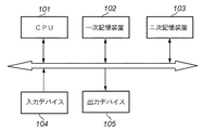
図1は、本発明の第1の実施形態に係る画像編集装置として機能可能な汎用コンピュータシステムの概略構成例を示した図である。CPU101は、システム全体の動作をコントロールし、一次記憶装置102に格納されたプログラムの実行などを行う。一次記憶装置102は主に半導体メモリであり、二次記憶装置103に記憶されたプログラムなどを読み込んで格納する。二次記憶装置103は、例えばハードディスクなどがこれに該当する。
[First Embodiment]
Hereinafter, the present invention will be described in detail based on preferred embodiments with reference to the drawings.
FIG. 1 is a diagram showing a schematic configuration example of a general-purpose computer system that can function as an image editing apparatus according to the first embodiment of the present invention. The
一般にコンピュータシステムにおいて一次記憶装置の容量は二次記憶装置の容量より小さく、一次記憶装置に格納しきれないプログラムやデータなどは二次記憶装置に格納される。また、長時間記憶しなくてはならないデータなども二次記憶装置に格納される。本実施形態では、CPU101が実行することでシステムを本実施形態の画像編集装置として機能させるプログラムを二次記憶装置103に格納し、プログラム実行時に一次記憶装置102に読み込んでCPU101が実行するものとする。入力デバイス104とは例えば、システムに対してユーザが指示を与えるために用いるマウスやキーボードといった入力装置の他、画像データの入力に必要なメモリカードリーダー、スキャナ、フィルムスキャナなどがこれに該当する。出力デバイス105とは例えば、モニタやプリンタなどが考えられる。システムの構成には他にも様々な形態が考えられるが、本発明の主眼ではないので説明を省略する。
Generally, in a computer system, the capacity of a primary storage device is smaller than the capacity of a secondary storage device, and programs and data that cannot be stored in the primary storage device are stored in the secondary storage device. Data that must be stored for a long time is also stored in the secondary storage device. In the present embodiment, a program that causes the system to function as the image editing apparatus of the present embodiment by being executed by the
本実施形態による画像編集装置には、複数のアプリケーションプログラムを並列実行可能なオペレーティングシステム(OS)が搭載され、操作者はOSが提供するGUI(Graphical User Interface)を介して装置上で動作するアプリケーションプログラムの操作を行うことができる。例えば本実施形態では、オペレーティングシステムとしてマイクロソフト社のWindows(登録商標)を用いるものとする。したがって、以下の説明においてはWindows(登録商標)の仕様に基づいた記述になっているが、これは本発明の実施環境を限定するものではなく、他のOS環境に本発明を適用可能であることは言うまでもない。
また、本実施形態に係る画像編集装置で実行可能な画像加工処理に特に制限はないが、以下では、従来技術で述べた領域複製処理を例として説明する。
The image editing apparatus according to the present embodiment includes an operating system (OS) capable of executing a plurality of application programs in parallel, and an operator operates on the apparatus via a GUI (Graphical User Interface) provided by the OS. Program operations can be performed. For example, in this embodiment, Windows (registered trademark) of Microsoft Corporation is used as the operating system. Therefore, in the following description, the description is based on the specifications of Windows (registered trademark), but this does not limit the implementation environment of the present invention, and the present invention can be applied to other OS environments. Needless to say.
In addition, there is no particular limitation on the image processing that can be executed by the image editing apparatus according to the present embodiment, but in the following, the area duplication processing described in the related art will be described as an example.
図2は、本実施形態の画像編集装置が領域複製処理時に提示するGUIの例を示す図である。加工対象画像は画像表示領域201に表示される。表示設定や加工パラメータを変更するためのパレット202には、コピー元位置指定モードボタン203、表示モード遷移ボタン204、全画面表示切り替えボタン205、コピー元座標を絶対座標として扱うか相対座標として扱うかを示すコピー元座標指定チェックボタン208、ブレンド領域の半径を指定する半径スライダ209、さらに、複数画像を加工対象とした場合の「次の画像」「前の画像」を選択する前選択ボタン210および次選択ボタン211、加工情報スタック(元画像データに対して適用された加工処理の内容を、加工処理の適用毎に記憶した工程情報の集合体。操作履歴。)を加工対象画像に添付する保存ボタン206、加工情報スタック適用後の画像をモニタやプリンタに出力するための変換ボタン207を備える。
FIG. 2 is a diagram illustrating an example of a GUI presented by the image editing apparatus according to the present embodiment at the time of area duplication processing. The processing target image is displayed in the image display area 201. The palette 202 for changing display settings and processing parameters includes a copy source position designation mode button 203, a display mode transition button 204, a full screen display switching button 205, and whether copy source coordinates are handled as absolute coordinates or relative coordinates. A copy source coordinate specification check button 208 indicating a radius, a radius slider 209 for specifying the radius of the blend area, a
図3は、領域複数処理において画像編集装置が取り扱うデータを示す図である。加工の対象となる画像は全て、ファイルリストに登録する。ファイルリストを構成するファイルエントリは、各画像のファイル名、画像回転情報および加工情報スタックを持つ。また、編集対象画像を示す編集対象画像ポインタがあり、このポインタで参照されているファイルエントリに対応するファイルが編集対象画像となる。 FIG. 3 is a diagram illustrating data handled by the image editing apparatus in the region multiple processing. All images to be processed are registered in the file list. A file entry constituting the file list has a file name of each image, image rotation information, and a processing information stack. In addition, there is an edit target image pointer indicating the edit target image, and a file corresponding to the file entry referred to by this pointer becomes the edit target image.
また、編集対象画像データとして、未加工状態の未加工画像データ、および後述する加工情報スタックに含まれる加工を適用した後のプレビュー画像データを持つ。未加工状態の画像データを保持するのは、後述するUndo/Redo処理のためである。図3中では、編集対象画像の加工情報スタックとファイルエントリの加工情報スタックとを別のデータとして表現しているが、編集対象画像データから直接ファイルエントリの加工情報スタックを参照しても良い。本実施形態では、直接ファイルエントリの加工情報スタックを参照する形をとる。 Further, the image data to be edited includes raw image data in an unprocessed state and preview image data after applying processing included in a processing information stack described later. The unprocessed image data is held for the undo / redo process described later. In FIG. 3, the modification information stack of the editing target image and the modification information stack of the file entry are expressed as different data. However, the modification information stack of the file entry may be directly referred to from the editing target image data. In the present embodiment, the processing information stack of the file entry is directly referred to.
また、1回のドラッグ操作によって複数の領域複製処理を1つの加工情報エントリに記録できるよう、ドラッグ操作に伴いOSから通知される座標を、適用座標列と呼ぶ配列に格納する。格納された座標の数は、適用座標数で保持する。したがって、領域複製処理を開始した時点で適用座標数を0に初期化する必要がある。 In addition, coordinates notified from the OS along with the drag operation are stored in an array called an applied coordinate sequence so that a plurality of region duplication processes can be recorded in one processing information entry by one drag operation. The number of stored coordinates is held as the number of applied coordinates. Therefore, it is necessary to initialize the number of applied coordinates to 0 when the area duplication process is started.
加工情報スタックを構成する各加工情報エントリ内には、加工パラメータと加工画像キャッシュがある。
加工パラメータとは、どの座標にどのような加工処理を適用したかを示す情報である。本実施形態では加工処理として領域複製処理のみを行うため、加工処理を識別するためのIDは保持しないが、加工パラメータの構成要素として加工処理を識別するIDを付与しても良いことは言うまでもない。本実施形態における加工パラメータは、領域複製処理範囲を示す半径r、適用座標列、および適用座標数とする。
In each processing information entry constituting the processing information stack, there are a processing parameter and a processing image cache.
The processing parameter is information indicating what processing is applied to which coordinates. In this embodiment, since only the region duplication process is performed as the processing process, an ID for identifying the processing process is not held, but it goes without saying that an ID for identifying the processing process may be given as a component of the processing parameter. . The processing parameters in the present embodiment are a radius r indicating an area duplication processing range, an applied coordinate sequence, and an applied coordinate number.
加工画像キャッシュとは、加工情報エントリに記録された画像加工処理を適用する前と適用した後の画像の差分である。このようなキャッシュを保持することで、実際に加工処理を実行するよりも高速に加工処理を実行できる。このキャッシュは、主にUndo/Redo処理で利用する。 The processed image cache is a difference between images before and after applying the image processing recorded in the processing information entry. By holding such a cache, the machining process can be executed at a higher speed than when the machining process is actually executed. This cache is mainly used for undo / redo processing.
本実施形態による画像編集プログラムでは、加工情報スタック以外の画像加工情報として画像回転情報を持つ。画像の回転方向については、画像データそのものを回転する場合もあるが、Exif(Exchangeable image file format for Digital Still Cameras)のOrientationタグに代表される、画像の回転方向を示す情報を付与することで、適切な画像の回転方向を保存する場合もある。後者は画像データ自体を変更しないため、回転処理のためのデコード処理による画質の劣化が無く、CCD−RAWデータに代表される特殊な画像データ形式にも対応可能である。 The image editing program according to the present embodiment has image rotation information as image processing information other than the processing information stack. Regarding the rotation direction of the image, the image data itself may be rotated, but by adding information indicating the rotation direction of the image, represented by the orientation tag of Exif (Exchangeable image file format for Digital Still Cameras), In some cases, an appropriate image rotation direction is stored. Since the latter does not change the image data itself, the image quality is not deteriorated by the decoding process for the rotation process, and it is possible to deal with a special image data format represented by CCD-RAW data.
そこで本実施形態では、加工情報スタックに合わせて画像の回転方向を示す画像回転情報を画像データに付与し、画像の回転結果を保持することとする。本実施形態においては、例えばキーボードのCtrlキーとLキーを同時に押下することで左90度回転、CtrlキーとRキーを同時に押下することで右90度回転の指示として動作する。画像回転情報や加工情報スタックの保存方法やデータ形式については後述する。 Therefore, in this embodiment, image rotation information indicating the rotation direction of the image is added to the image data in accordance with the processing information stack, and the rotation result of the image is held. In the present embodiment, for example, when the Ctrl key and the L key of the keyboard are pressed simultaneously, the left rotation is performed by 90 degrees, and when the Ctrl key and the R key are pressed simultaneously, the operation is performed as an instruction for rotating the right 90 degrees. The storage method and data format of the image rotation information and the processing information stack will be described later.
図4は、本実施形態にかかる画像編集装置が出力デバイス105としての表示装置に表示するGUIの状態遷移図である。
GUIは画像をウィンドウの大きさに合わせた倍率で表示(fit表示)するfitモード401と、画素等倍表示にする等倍モード402の2モードに分かれており、遷移コマンドによって互いの状態へ遷移する。本実施形態では、fitモード時は画像加工を禁止し、等倍モードでのみ画像加工ができるように制御している。これは、画像加工を実行する範囲が広くなると、加工前画像と加工後画像の差分である加工画像キャッシュのデータサイズが大きくなり、処理に必要なメモリ領域が非常に大きなものになってしまうからである。画像加工操作を等倍モードに限定することで、画像加工範囲を限定し、使用メモリ量の増加を抑制することができる。
FIG. 4 is a state transition diagram of the GUI displayed on the display device as the
The GUI is divided into two modes: a
fitモード時は、等倍モードへの遷移のみ可能である。本実施形態において、画像編集装置は、表示モード遷移ボタン204が押下されるか、画像表示領域201にfit表示されている画像のどこかがダブルクリックされると、等倍モードへ移行する。表示モード遷移ボタン204が押下された場合、編集対象画像の中央部を画素等倍表示し、等倍モードに遷移する。また、fit表示画像がダブルクリックされた場合、ダブルクリックされた画像位置が中央に表示されるように画素等倍表示する。等倍表示時の画像外領域は、黒で塗りつぶす。 In the fit mode, only the transition to the normal magnification mode is possible. In the present embodiment, the image editing apparatus shifts to the normal magnification mode when the display mode transition button 204 is pressed or when an image displayed in the image display area 201 is double-clicked. When the display mode transition button 204 is pressed, the central portion of the image to be edited is displayed in the same size pixel, and the mode is changed to the same size mode. Further, when the fit display image is double-clicked, the same-size pixel display is performed so that the double-clicked image position is displayed in the center. The area outside the image at the same magnification display is filled with black.
等倍モード時は、画像加工ができる。等倍モード時の状態遷移図を図5に示す。fitモードから等倍モードに遷移した直後は、移動モード502になる。移動モード502の状態で画像がダブルクリックされるか、表示モード遷移ボタン204が押下されると、fitモードへ遷移する。
Image processing can be performed in the same magnification mode. FIG. 5 shows a state transition diagram in the same magnification mode. Immediately after the transition from the fit mode to the equal magnification mode, the
移動モード502では、画像表示位置の変更が可能である。一般的なウィンドウ表示と同様、垂直、水平スクロールバーの操作によりユーザは画像表示位置の変更ができる。
移動モード502、あるいはスタンプモード504でAltキーが押下されている間、あるいはコピー元位置指定モードボタン203が押下されると、コピー元位置指定モード503に遷移する。Altボタンが開放されるか、コピー元位置指定モードボタン203が再度押下されると、移動モード502に遷移する。表示モード遷移ボタン204が押下されると、fitモード501へ戻る。コピー元位置指定モード503において画像上がクリックされた場合、そのクリック位置をコピー元座標としてスタンプモード504に遷移する。
In the
When the Alt key is pressed in the
スタンプモード504に入った後、最初にマウスの左ボタンがクリック(左クリック)された座標に対し、領域複製処理を行う。この座標を基準座標と呼ぶ。基準座標が更新された場合、コピー相対座標を未設定状態にする。コピー相対座標とは、領域複製処理のコピー先の領域からコピー元の領域への相対座標である。
After entering the
スタンプモード504において右クリックされた場合、移動モード502に遷移する。移動モードで表示モード遷移ボタン204が押下されると、fitモード501へ戻る。
When the user right-clicks in the
次に、図6に示すフローチャートを用いて領域複製処理の流れについて説明する。ここで図6中の複製マスクとは、半径スライダ209の状態に応じて生成した複製マスクである。複製マスクの生成処理は、半径スライダ209の状態が変化する度に実行する。複製マスク生成処理については後述する。 Next, the flow of region duplication processing will be described using the flowchart shown in FIG. Here, the duplication mask in FIG. 6 is a duplication mask generated according to the state of the radius slider 209. The duplication mask generation process is executed every time the state of the radius slider 209 changes. The duplicate mask generation process will be described later.
(ステップS601) コピー相対座標が設定されているかどうかをチェックする。設定されていればステップS603へ、設定されていなければステップS602へ進む。
(ステップS602) コピー元位置から基準座標への相対座標を求め、これをコピー相対座標とする。
(ステップS603) コピー元位置の相対座標を算出する。コピー元位置を絶対座標として扱う場合、基準座標とコピー先座標の相対座標を用いる。コピー元位置を相対座標として扱う場合、コピー相対座標を用いる。
(Step S601) It is checked whether copy relative coordinates are set. If it is set, the process proceeds to step S603, and if it is not set, the process proceeds to step S602.
(Step S602) Relative coordinates from the copy source position to the reference coordinates are obtained and set as copy relative coordinates.
(Step S603) The relative coordinates of the copy source position are calculated. When the copy source position is handled as absolute coordinates, the relative coordinates of the reference coordinates and the copy destination coordinates are used. When the copy source position is handled as relative coordinates, the copy relative coordinates are used.
(ステップS604) 適用座標数を0に初期化し、プレビューキャッシュ画像を作成する。プレビューキャッシュ画像とは、この時点でのプレビュー画像のコピーである。
(ステップS605) マウスの左ボタンの状態をチェックする。左ボタンが押下されている場合は、ステップS606へ進む。そうでない場合はステップS608へ進む。
(ステップS606) マウスカーソルが指し示す座標をコピー先座標とし、複製マスクを用いてコピー相対座標からのブレンド処理を行う。複製マスク、およびブレンド処理の詳細については後述する。
(ステップS607) 適用座標数を1増やし、適用座標列にコピー先座標を追加する。ステップS605へ戻る。
(ステップS608) 加工情報スタック終端位置情報より先にある加工情報エントリを破棄する。
(Step S604) The number of applied coordinates is initialized to 0, and a preview cache image is created. The preview cache image is a copy of the preview image at this point.
(Step S605) The state of the left button of the mouse is checked. If the left button is pressed, the process proceeds to step S606. Otherwise, the process proceeds to step S608.
(Step S606) The coordinates pointed to by the mouse cursor are set as the copy destination coordinates, and the blending process from the copy relative coordinates is performed using the duplication mask. Details of the duplication mask and the blending process will be described later.
(Step S607) The number of applied coordinates is increased by 1, and the copy destination coordinates are added to the applied coordinate sequence. The process returns to step S605.
(Step S608) The processing information entry ahead of the processing information stack end position information is discarded.
(ステップS609) 新たな加工情報エントリを作成し、これを参照するように加工情報スタック終端位置情報を更新する。
(ステップS610) ステップS604で作成したプレビューキャッシュ画像とプレビュー画像との差分画像を作成する。この差分画像を、ステップS609で作成した加工エントリの加工画像キャッシュとする。プレビューキャッシュには、キャッシュ作成時の回転方向を示すキャッシュ回転情報を付与しておく。
(ステップS611) ステップS609で作成した加工情報エントリの加工パラメータとして、半径r、コピー相対座標、適用座標数、適用座標列を登録する。ここで、コピー相対座標、適用座標列は、画像回転情報を用いて、画像回転処理適用前の座標に変換して登録する。このような処理により、画像の回転方向が変更されたとしても常に適切な位置に加工処理を適用することが可能になる。
(Step S609) A new machining information entry is created, and the machining information stack end position information is updated so as to refer to this.
(Step S610) A difference image between the preview cache image created in step S604 and the preview image is created. This difference image is used as the processed image cache of the processed entry created in step S609. The preview cache is provided with cache rotation information indicating the rotation direction when the cache is created.
(Step S611) The radius r, the copy relative coordinate, the number of applied coordinates, and the applied coordinate sequence are registered as the machining parameters of the machining information entry created in Step S609. Here, the copy relative coordinates and the applied coordinate string are registered after being converted into coordinates before application of the image rotation process using the image rotation information. By such processing, even if the rotation direction of the image is changed, it is possible to always apply the processing processing to an appropriate position.
次に、ブレンド処理の詳細について説明する。ブレンド処理とは、コピー先座標を中心とした半径rの領域に、コピー元座標を中心とした半径rの領域を合成処理することである。実際にはコピー先座標から離れるほどコピー元座標の比率を落として合成処理しないと、領域複製処理を行った部分と行っていない部分の境界部分が目立ってしまうので、コピー先座標から離れるほど合成比率を落とすような処理になる。そこで、合成処理を、半径rの2倍の範囲で行う。この合成の比率を示すマップのことを、複製マスクと呼ぶ。 Next, details of the blending process will be described. The blending process is a process of synthesizing an area having a radius r centered on the copy source coordinates with an area having a radius r centered on the copy destination coordinates. Actually, if you do not perform the compositing process by reducing the ratio of the copy source coordinates as you move away from the copy destination coordinates, the boundary part between the part that has undergone the area duplication process and the part that has not been performed will become conspicuous. It becomes processing that drops the ratio. Therefore, the synthesizing process is performed in a range twice the radius r. The map showing the composition ratio is called a replication mask.
まず、複製マスクの概要を図7に示す。複製マスクの各要素の値域は、[0.0,1.0]である。この値が大きいほどコピー元領域の画素値が優先される。複製マスクの要素は、複製マスクの中心(Cx,Cy)からの距離に応じて算出される値で算出する。この計算方法については後述する。コピー元座標F、コピー先座標Tをそれぞれ、x座標を−2*r、y座標を−2*rとした座標、複製マスクの左上を原点とした場合、座標(i,j)にある画素のブレンド処理を、次式に従って画素値を求める。
T’i,j=Bi,j*Fi,j+(1.0−Bi,j)*Ti,j
ここで、Fはコピー元座標の画素、Tはコピー先領域の画素、Bは複製マスクの要素、T’はブレンド処理後のコピー先領域の画素とする。本実施形態では各画素のRGBそれぞれの値をブレンド率に応じて合成してブレンド後の画素値を算出する。
First, an outline of the replication mask is shown in FIG. The range of each element of the replication mask is [0.0, 1.0]. The larger this value, the higher the priority is given to the pixel value in the copy source area. The element of the duplication mask is calculated with a value calculated according to the distance from the center (Cx, Cy) of the duplication mask. This calculation method will be described later. If the copy source coordinate F and the copy destination coordinate T are the coordinates where the x coordinate is −2 * r and the y coordinate is −2 * r, respectively, and the upper left corner of the copy mask is the origin, the pixel at the coordinates (i, j) In this blending process, the pixel value is obtained according to the following equation.
T ′ i, j = B i, j * F i, j + (1.0−B i, j ) * T i, j
Here, F is a pixel of the copy source coordinate, T is a pixel of the copy destination region, B is an element of the copy mask, and T ′ is a pixel of the copy destination region after the blending process. In the present embodiment, the RGB values of each pixel are combined according to the blend rate to calculate the pixel value after blending.
図6に示した処理においてマウスがドラッグ操作された場合の、ドラッグ中のマウスポインタの軌跡に対する処理について述べる。Windows(登録商標)では、ドラッグ中にマウスポインタが通過した全ての座標がOSからアプリケーションに通知されるわけではなく、一定間隔で通知される。しかし、この間隔が比較的長い。そこで、ドラッグ状態を示す通知を受けた場合、その座標A(xa,ya)と直前に通知された座標B(xb,yb)とを結ぶ線分上に一定距離L毎に領域複製処理を行う。このような処理を行うことで滑らかな領域複製結果を得ることができる。 Processing for the locus of the mouse pointer being dragged when the mouse is dragged in the processing shown in FIG. 6 will be described. In Windows (registered trademark), not all coordinates that the mouse pointer passes during dragging are notified from the OS to the application, but are notified at regular intervals. However, this interval is relatively long. Therefore, when a notification indicating the drag state is received, a region duplication process is performed for each fixed distance L on a line segment connecting the coordinate A (xa, ya) and the coordinate B (xb, yb) notified immediately before. . By performing such processing, a smooth region duplication result can be obtained.
ここで、ドラッグ中の領域複製処理を適用する点の間隔Lを、半径スライダ209で指定された半径rを用いて次式で求める。
L=floor(r/B+0.5)
ただし、L=0の場合、L=1として処理する。ここで、floor(x)は、実数xの小数点以下を切り捨てした整数値を表す。また、Bは経験的に求められる値で、本実施形態ではB=4.7とする。
Here, the distance L between the points to which the region duplication process during dragging is applied is obtained by the following equation using the radius r designated by the radius slider 209.
L = floor (r / B + 0.5)
However, when L = 0, L = 1 is processed. Here, floor (x) represents an integer value obtained by rounding down the decimal point of the real number x. B is a value empirically obtained, and in this embodiment, B = 4.7.
ここで、図7に示した複製マスクの要素の計算方法について述べる。マスクの要素Bi,jは、次式で求める。 Here, a method for calculating the elements of the replication mask shown in FIG. 7 will be described. The mask element Bi, j is obtained by the following equation.

Cx、Cyは図7中に示したマスクの中央座標で、本実施形態では(Cx,Cy)=(2*r,2*r)とする。したがって、複製マスクサイズは、幅(4*r+1)要素、高さ(4*r+1)要素となる。i、jは左上を(i,j)=(0,0)とする座標値であり、i,jの値域は[0,4*r]となる。rは半径スライダ209で指定された半径である。 Cx and Cy are the central coordinates of the mask shown in FIG. 7, and in this embodiment, (Cx, Cy) = (2 * r, 2 * r). Therefore, the duplicate mask size is a width (4 * r + 1) element and a height (4 * r + 1) element. i and j are coordinate values with (i, j) = (0, 0) in the upper left, and the range of i and j is [0, 4 * r]. r is a radius specified by the radius slider 209.
次に、図8に示すフローチャートを用いて、編集対象画像ファイルが指定された場合や前選択ボタン210や次選択ボタン211によって編集対象画像が変更された場合の編集対象画像切り替え処理について説明する。
Next, an editing target image switching process when an editing target image file is designated or when the editing target image is changed by the
(ステップS801) 編集対象画像の加工情報スタックについて、加工情報スタック終端情報より先の加工情報エントリを破棄する。
(ステップS802) 編集対象画像の加工情報スタックについて、加工情報スタックの加工情報キャッシュを全て破棄する。
(ステップS803) 新たに選択されたファイルのファイルエントリを参照するように、編集対象情報ポインタを更新する。
(Step S801) For the modification information stack of the image to be edited, the modification information entry ahead of the modification information stack end information is discarded.
(Step S802) For the processing information stack of the image to be edited, all processing information caches in the processing information stack are discarded.
(Step S803) The edit target information pointer is updated so as to refer to the file entry of the newly selected file.
(ステップS804) 編集対象画像ポインタが参照する加工情報スタックを参照するように、編集対象画像の加工情報スタックの参照先を更新する。
(ステップS805) ファイルをデコードし、編集対象画像データ中の未加工画像を取得する。
(ステップS806) ステップS805で得た未加工画像に対し、加工情報スタックに保持された加工処理を適用し、プレビュー画像を生成する。加工処理の詳細については図9を用いて後述する。
(ステップS807) GUIの状態をfitモード401に遷移して、プレビュー画像をfit表示する。
(Step S804) The reference destination of the modification information stack of the editing target image is updated so that the modification information stack referred to by the editing target image pointer is referred to.
(Step S805) The file is decoded and an unprocessed image in the image data to be edited is acquired.
(Step S806) The processing held in the processing information stack is applied to the unprocessed image obtained in step S805 to generate a preview image. Details of the processing will be described later with reference to FIG.
(Step S807) The GUI state is changed to the
次に、本実施形態におけるUndo/Redo処理について述べる。
Undoとは、直前に適用した加工処理を取り消す処理である。本実施形態では、加工情報スタック終端位置情報を、一つ前の加工情報エントリを参照するよう修正することにより、Undo処理が実現できる。
Next, the Undo / Redo process in this embodiment will be described.
Undo is processing for canceling the processing applied immediately before. In the present embodiment, the undo process can be realized by modifying the machining information stack end position information so as to refer to the previous machining information entry.
また、Redoとは、Undoの取り消し処理、すなわちやり直し処理である。本実施形態では、加工情報スタック終端位置情報を、参照中の加工スタックエントリの次のエントリを参照するように更新することにより、Redo処理が実現できる。 Redo is an undo cancellation process, that is, a redo process. In the present embodiment, the redo process can be realized by updating the machining information stack end position information so as to refer to the entry next to the machining stack entry being referred to.
このように、加工情報エントリと加工情報スタック終端位置情報を用いることで、加工情報スタック終端位置情報の参照先を変更するだけでUndo/Redo機能が実現可能であり、加工処理を適用した座標が間違っている場合や加工結果が思わしくない場合でも、何度でもやりなおしすることができるようになる。 Thus, by using the machining information entry and the machining information stack end position information, the Undo / Redo function can be realized simply by changing the reference destination of the machining information stack end position information. Even if it is wrong or the processing result is not good, you can try again and again.
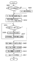
Undo/Redo処理や新たな編集対象画像ファイルが選択された場合、プレビュー画像の更新処理が必要になる。プレビュー画像の更新処理は、未加工画像に対して加工情報スタックに従って加工処理を適用して行う。以下、プレビュー画像の更新処理の詳細について、図9に示すフローチャートを用いて説明する。なお、加工情報スタックが空の場合には、この処理を適用しない。 When an undo / redo process or a new image file to be edited is selected, a preview image update process is required. The update process of the preview image is performed by applying the modification process to the unprocessed image according to the modification information stack. Details of the preview image update processing will be described below with reference to the flowchart shown in FIG. Note that this processing is not applied when the machining information stack is empty.
(ステップS901) 現在のプレビュー画像を破棄した後、未加工画像を複製し、この複製をプレビュー画像とする。このプレビュー画像は、画像回転情報が示す方向になるように回転処理する。
(ステップS902) 加工情報スタックが参照する加工情報エントリを示すポインタpを作成する。
(ステップS903) ポインタpが示す加工情報エントリに加工画像キャッシュが存在するかどうかをチェックする。存在する場合はステップS904へ、存在しない場合はS905へ進む。
(Step S901) After discarding the current preview image, the raw image is duplicated, and this duplicate is used as the preview image. This preview image is rotated so as to be in the direction indicated by the image rotation information.
(Step S902) A pointer p indicating a machining information entry referred to by the machining information stack is created.
(Step S903) It is checked whether or not a modified image cache exists in the modified information entry indicated by the pointer p. When it exists, it progresses to step S904, and when it does not exist, it progresses to S905.
(ステップS904) 画像回転情報とキャッシュ回転情報を比較し、画像回転情報で指定された画像の方向に合うように、差分画像を回転し、差分をプレビュー画像に反映する。ステップS906へ進む
(ステップS905) ポインタpが示す加工情報エントリの加工パラメータを用い、プレビュー画像に加工処理を適用する。ただし、加工処理を適用する前に、コピー相対座標、適用座標列に格納された座標を、画像回転情報が示す方向に回転し、回転後の座標に対して加工処理を適用する。加工処理適用後、ステップS906へ進む。
(ステップS906) 次の加工情報エントリが存在する場合、ステップS907へ進む。存在しない場合は、処理を終了する。
(ステップS907) ポインタpが次の加工情報エントリを参照するようにポインタを更新し、ステップS903へ戻る。
(Step S904) The image rotation information and the cache rotation information are compared, the difference image is rotated so as to match the direction of the image specified by the image rotation information, and the difference is reflected in the preview image. Proceeding to step S906 (step S905) The processing process is applied to the preview image using the processing parameter of the processing information entry indicated by the pointer p. However, before applying the processing, the copy relative coordinates and the coordinates stored in the applied coordinate sequence are rotated in the direction indicated by the image rotation information, and the processing is applied to the rotated coordinates. After applying the processing, the process proceeds to step S906.
(Step S906) If the next machining information entry exists, the process proceeds to step S907. If it does not exist, the process ends.
(Step S907) The pointer is updated so that the pointer p refers to the next processing information entry, and the process returns to step S903.
ここで、図2における保存ボタン206と変換ボタン207について説明する。保存ボタン206が押下された場合、加工情報スタックおよび画像回転情報を編集対象画像ファイルに付与する。この機能を用意することで、元画像データ(未加工画像データ)を維持したまま加工結果を保存することができる。変換ボタン207が押下された場合、編集対象画像データファイル中の元画像データに対し、加工情報スタックに応じた画像処理を適用し、画像回転情報に従って画像を回転後、新たなファイルとして保存する。画像の回転前に加工情報スタックを適用することで、加工情報スタック内の座標変換を行わなくても良いという利点がある。しかし、本実施形態では処理の共通化のため、画像回転情報に合わせて画像を回転した後、図9に示す処理によって加工情報スタックに沿った加工処理を適用する。 Here, the save button 206 and the conversion button 207 in FIG. 2 will be described. When the save button 206 is pressed, the modification information stack and the image rotation information are added to the image file to be edited. By preparing this function, it is possible to save the processing result while maintaining the original image data (unprocessed image data). When the conversion button 207 is pressed, image processing corresponding to the processing information stack is applied to the original image data in the image data file to be edited, the image is rotated according to the image rotation information, and then saved as a new file. By applying the processing information stack before the rotation of the image, there is an advantage that it is not necessary to perform coordinate conversion in the processing information stack. However, in this embodiment, in order to make the processing common, after the image is rotated according to the image rotation information, the processing along the processing information stack is applied by the processing shown in FIG.
保存ボタン206によって付与されるデータ形式の一例を図10に示す。図10に示すデータを加工情報と呼ぶ。
画像回転方向は、回転しない状態を「0」、右90度回転時は「1」、180度回転時は「2」、左90度回転時は「3」を2バイトで格納する。加工情報スタックエントリ数は4バイトで、加工情報スタックエントリの数を格納する。加工情報スタックエントリ内には、処理識別ID、適用半径、画像回転前の座標値で表現されたコピー相対座標および適用座標と、適用座標の数を保持する。座標はx座標2バイト、y座標2バイトの計4バイトで、その他の数値は2バイトとする。処理識別IDは、将来加工処理の種類を増やした時に対応するために設けられ、本実施形態では常に0x0001を格納する。
An example of the data format given by the save button 206 is shown in FIG. The data shown in FIG. 10 is called processing information.
As the image rotation direction, “0” is stored when the image is not rotated, “1” when rotated 90 degrees to the right, “2” when rotated 180 degrees, and “3” when rotated 90 degrees to the left. The number of machining information stack entries is 4 bytes and stores the number of machining information stack entries. In the processing information stack entry, a process identification ID, an application radius, copy relative coordinates and application coordinates expressed by coordinate values before image rotation, and the number of application coordinates are held. The coordinate is 2 bytes for x coordinate and 2 bytes for y coordinate, and the other numerical values are 2 bytes. The process identification ID is provided to cope with an increase in the types of future processing processes, and always stores 0x0001 in this embodiment.
加工情報は、JPEGデータのEOI(End Of Image)の後やTiffデータの末尾、CCD−RAWデータファイルの末尾に付与することができる。ただし、CCD−RAWデータファイルの末尾に特別な意味、例えばCCD−RAWファイルの識別コードなどが含まれている場合があるため、加工情報の末尾の16バイトには加工情報をファイルに添付する前のファイルの末尾16バイトをコピーして記録する互換エリアを設けている。また、ファイルに添付された加工情報があるかどうかを判定するため、互換エリアの直前に、識別情報”ADT” 0、および、加工データの先頭を検出するためのデータ長をそれぞれ4バイトで格納する。 Processing information can be added after EOI (End Of Image) of JPEG data, at the end of Tiff data, or at the end of a CCD-RAW data file. However, there are cases where a special meaning such as an identification code of the CCD-RAW file is included at the end of the CCD-RAW data file, so the last 16 bytes of the processing information are before the processing information is attached to the file. A compatible area for copying and recording the last 16 bytes of the file is provided. Also, in order to determine whether or not there is processing information attached to the file, the identification information “ADT” 0 and the data length for detecting the top of the processing data are stored in 4 bytes immediately before the compatible area. To do.
次に、図11に示すフローチャートを用いて、本実施形態における加工情報の読み込み処理について説明する。
(ステップS1101) 識別情報の有無を確認するため、最初にファイル末尾から24バイト目の位置から4バイト読み込む。
(ステップS1102) ステップS1101で読み込んだデータが識別情報”ADT” 0であるかどうかをチェックし、加工情報が画像データに付与されているかどうかを判定する。識別情報が検出された場合には加工情報が付与されていると判定し、ステップS1103へ進み、そうでない場合は読み込み処理を終了する。
(ステップS1103) ファイル末尾から20バイト目の位置から4バイト読み込み、加工情報のデータ長を取得する。
(ステップS1104) 互換エリアの先頭から加工情報のデータ長分戻った位置からファイル末尾までを読み込む。読み込んだデータが加工情報である。なお、予めデータ長として互換エリアの16バイト分が追加してある場合にはファイルの末尾からデータ長分戻った位置から読み込めばよい。
Next, processing information reading processing according to the present embodiment will be described with reference to the flowchart shown in FIG.
(Step S1101) In order to confirm the presence / absence of identification information, first, 4 bytes are read from the position of the 24th byte from the end of the file.
(Step S1102) It is checked whether or not the data read in Step S1101 is the identification information “ADT” 0, and it is determined whether or not the processing information is added to the image data. If the identification information is detected, it is determined that the processing information is given, and the process proceeds to step S1103. If not, the reading process is terminated.
(Step S1103) 4 bytes are read from the position of the 20th byte from the end of the file, and the data length of the processing information is acquired.
(Step S1104) The portion from the position returned from the beginning of the compatible area by the data length of the processing information to the end of the file is read. The read data is processing information. If 16 bytes of the compatible area have been added as the data length in advance, the data length may be read from the position returned from the end of the file.
以上説明したように、本実施形態によれば、未加工の画像データとそれに適用された加工処理とを個別に保存することにより、編集加工対象となる元画像データに変更を加えることなく加工を適用し、加工結果を保存することが可能になる。 As described above, according to the present embodiment, the raw image data and the processing applied to the raw image data are individually saved, so that the original image data to be edited is processed without any change. It is possible to apply and save the processing result.
また、加工処理を工程毎に保存するため、適用した加工を段階的に取り消すことが可能であるほか、取り消した加工処理を再度適用することも可能である。 In addition, since the processing is stored for each process, the applied processing can be canceled step by step, and the canceled processing can be applied again.
〔第2の実施形態〕
本実施形態では、第1の実施形態で述べたシステム上における、異なる画像間での加工情報スタックのコピー&ペーストについて述べる。ほぼ似た絵柄の画像が複数ある場合、一枚の画像に対して加工処理を行い、同様の処理を別の画像に適用することで、加工作業に費やす時間を削減することができる。本実施形態による画像編集装置では、第1の実施形態と同様、編集(加工)手順を加工情報スタックという形で保持しているため、この加工情報スタックだけを別の画像データファイルへ適用することで、同じ加工処理を実現可能である。
[Second Embodiment]
In this embodiment, a copy and paste of a processing information stack between different images on the system described in the first embodiment will be described. In the case where there are a plurality of images having substantially similar patterns, the processing time is performed on one image, and the same processing is applied to another image, so that the time spent on the processing work can be reduced. In the image editing apparatus according to the present embodiment, as in the first embodiment, the editing (processing) procedure is held in the form of a processing information stack. Therefore, only this processing information stack is applied to another image data file. Thus, the same processing can be realized.
まず、加工情報スタックのコピー処理について述べる。加工情報スタックのコピー処理とは、編集対象画像の加工情報スタックを例えば一次記憶装置の領域として確保されるコピーバッファに格納する処理である。ただし、コピーした加工情報スタックをペーストする場合、ペーストするかどうかの判断にコピー元画像の解像度が必要になるため、これを別途保持する。コピーバッファに格納する情報は、加工情報スタック、画像回転情報、元画像の回転処理前の画像解像度である。 First, processing information stack copy processing will be described. The copy processing of the modification information stack is a process of storing the modification information stack of the image to be edited in, for example, a copy buffer secured as an area of the primary storage device. However, when pasting the copied processing information stack, the resolution of the copy source image is required to determine whether to paste or not, and this is held separately. The information stored in the copy buffer is the processing information stack, the image rotation information, and the image resolution before the original image rotation process.
次に、加工情報スタックのペースト処理について述べる。加工情報スタックのペースト処理とは、コピー処理によってコピーバッファ内に保持された加工情報スタックを、編集対象画像データファイルに添付、或いはその加工情報スタックに反映する処理である。 Next, processing information stack paste processing will be described. The processing information stack paste processing is processing for attaching the processing information stack held in the copy buffer by the copy processing to the editing target image data file or reflecting the processing information stack in the processing information stack.
ペースト処理には、編集対象画像の加工情報スタックに、ペーストする加工情報スタックを付加する方法と、編集対象画像の加工情報スタックを破棄し、ペーストする加工情報スタックに置き換える方法がある。本実施形態では、後者を用いるものとする。 The paste processing includes a method of adding a processing information stack to be pasted to a processing information stack of an image to be edited and a method of discarding the processing information stack of an image to be edited and replacing it with a processing information stack to be pasted. In the present embodiment, the latter is used.
図12は、本実施形態におけるペースト処理を説明するフローチャートである。
(ステップS1201) ペースト処理実行判定を行う。本実施形態では、コピーバッファに格納された元画像の回転前の画像解像度と、ペースト対象画像の回転前の画像解像度を比較し、画像の幅および高さが一致した場合のみ、ペースト処理を実行可能であると判定する。ペースト処理が実行できない場合は処理を終了し、そうでない場合はステップS1202へ進む。
(ステップS1202) ペースト対象画像データファイル内の加工情報スタックを破棄する。
(ステップS1203) コピーバッファ内の加工情報スタックを複製し、これをペースト対象画像の加工情報スタックとして置き換えることによって更新する。
(ステップS1204) 更新された加工情報スタックを用い、ペースト対象画像に対して図9に示した加工処理を実行し、プレビュー画像、および加工画像キャッシュの再構成を行い、処理を終了する。
FIG. 12 is a flowchart for explaining paste processing in the present embodiment.
(Step S1201) Paste process execution determination is performed. In this embodiment, the image resolution before rotation of the original image stored in the copy buffer is compared with the image resolution before rotation of the paste target image, and only when the width and height of the images match, paste processing is executed. Determine that it is possible. If the paste process cannot be executed, the process ends. If not, the process proceeds to step S1202.
(Step S1202) The processing information stack in the paste target image data file is discarded.
(Step S1203) The processing information stack in the copy buffer is copied and updated by replacing it with the processing information stack of the paste target image.
(Step S1204) Using the updated processing information stack, the processing shown in FIG. 9 is executed on the paste target image, the preview image and the processed image cache are reconfigured, and the processing ends.
このように、本実施形態によれば、加工情報スタックを他の画像データファイルに適用することで、共通の画像加工処理を実現することが可能である。従って、類似の複数画像に対して同じ処理を適用する場合、ある1つの画像に対して加工処理を行えば、残りの画像に対しては加工情報をコピーペーストするだけでよく、使い勝手がよい。 As described above, according to this embodiment, it is possible to realize a common image processing process by applying the processing information stack to another image data file. Therefore, when the same processing is applied to a plurality of similar images, if processing is performed on a certain image, it is only necessary to copy and paste the processing information for the remaining images, which is convenient.
〔第3の実施形態〕
第2の実施形態では、加工情報スタックのコピー元画像の解像度と、ペーストしようとしている画像の解像度が完全に一致する場合だけ、ペースト処理が実行可能であると判定した。しかし、近年のデジタルカメラの中には、解像度が異なるだけの全く同じ絵柄の画像データを同時に生成するものもある。第2の実施形態のような判定では、このような複数の画像間での加工情報スタックの共通利用に対応できない。
[Third Embodiment]
In the second embodiment, it is determined that the paste process can be executed only when the resolution of the copy source image of the processing information stack completely matches the resolution of the image to be pasted. However, some recent digital cameras simultaneously generate image data with exactly the same pattern with different resolutions. The determination as in the second embodiment cannot cope with the common use of the processing information stack between the plurality of images.
そのため、本実施形態では、加工情報スタックのペースト先の画像の解像度に応じて加工情報中の座標を変換することで、このような画像間での加工情報スタックの共通利用を実現するものである。ただし、アスペクト比(縦横比)が異なる画像については画像が切り抜かれている場合も考えられるので、本実施形態ではペースト処理対象としない。 For this reason, in the present embodiment, the coordinate in the processing information is converted according to the resolution of the paste image of the processing information stack, thereby realizing common use of the processing information stack between such images. . However, since images with different aspect ratios (aspect ratios) may be cut out, they are not subject to paste processing in this embodiment.
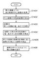
本実施形態におけるペースト処理について、図13に示すフローチャートに基づき説明する。
(ステップS1301) ペースト処理実行判定を行う。本実施形態では、コピーバッファに格納された、元画像の回転前の画像解像度と、ペースト対象画像の回転前の画像解像度を比較し、画像のアスペクト比が実質的に一致した場合のみ、ペースト処理を実行する。ここで完全一致を条件としないのは、同じ画像を縮小した場合でもアスペクト比が完全に一致しない場合があるためである。アスペクト比の差が予め定められた数値内である場合に一致するとみなす。ペースト処理を実行できないと判断される場合は処理を終了し、そうでない場合はステップS1302へ進む。
(ステップS1302) ペースト対象画像データファイルの加工情報スタックを破棄する。
The paste process in this embodiment will be described based on the flowchart shown in FIG.
(Step S1301) The paste process execution determination is performed. In the present embodiment, the image resolution before rotation of the original image stored in the copy buffer is compared with the image resolution before rotation of the paste target image, and only when the image aspect ratio substantially matches, the paste processing Execute. The reason why the complete match is not used here is that the aspect ratio may not be completely matched even when the same image is reduced. When the difference in aspect ratio is within a predetermined numerical value, it is considered to match. If it is determined that the paste process cannot be executed, the process ends. If not, the process proceeds to step S1302.
(Step S1302) The processing information stack of the paste target image data file is discarded.
(ステップS1303) コピーバッファ内に格納された、元画像の加工情報スタックを複製し、これをペースト対象画像の加工情報スタックとして置き換える。
(ステップS1304) コピー元画像の画像解像度と、ペースト対象画像の画像解像度を用い、ペースト対象画像の加工情報スタックに含まれる座標を変換する。加工情報スタックに保持されている座標(X,Y)について、コピー元座標の画像解像度を幅Wc、高さHc、ペースト対象画像の画像解像度を幅Wp、高さHpとすると、変換後の座標(X’,Y’)は、
X’=X*Wp/Wc
Y’=Y*Hp/Hc
となる。
(Step S1303) The processing information stack of the original image stored in the copy buffer is duplicated and replaced with the processing information stack of the paste target image.
(Step S1304) Using the image resolution of the copy source image and the image resolution of the paste target image, the coordinates included in the processing information stack of the paste target image are converted. Regarding the coordinates (X, Y) held in the processing information stack, if the image resolution of the copy source coordinates is width Wc and height Hc, and the image resolution of the paste target image is width Wp and height Hp, the coordinates after conversion (X ', Y') is
X ′ = X * Wp / Wc
Y ′ = Y * Hp / Hc
It becomes.
また、画像処理の適用半径も、次式で変換する。rが変換前、r’が変換後の値である。 The application processing radius is also converted by the following equation. r is a value before conversion, and r 'is a value after conversion.
(ステップS1305) 変更後の加工情報スタックを用い、ペースト対象画像に対して図9に示した加工処理を実行し、プレビュー画像、および加工画像キャッシュの再構成を行い、処理を終了する。 (Step S1305) Using the modified modification information stack, the modification process shown in FIG. 9 is executed for the paste target image, the preview image and the modified image cache are reconfigured, and the process ends.
このように、本実施形態によれば、コピーもと画像とペースト先画像の解像度に基づいて加工情報スタックに含まれる座標を変換することにより、解像度の異なる同一画像間での加工情報スタックの共通利用が可能になる。 As described above, according to this embodiment, by converting the coordinates included in the processing information stack based on the resolution of the copy source image and the paste destination image, the processing information stack can be shared between the same images having different resolutions. Can be used.
〔第4の実施形態〕
本実施形態は、第1の実施形態で述べた画像編集装置での印刷処理に関する。
加工後の画像を印刷する場合、一般的には、未加工画像に対して加工情報スタックにある編集内容を適用し、その後印刷解像度に変換してプリンタへ出力することが考えられる。しかし、上述したように、画像加工処理、特に領域複製処理においては、適用領域が小さいほど処理が高速に実行できる。
[Fourth Embodiment]
This embodiment relates to a printing process in the image editing apparatus described in the first embodiment.
When printing a processed image, it is generally considered that the editing content in the processing information stack is applied to an unprocessed image, and then converted to a print resolution and output to a printer. However, as described above, in the image processing process, particularly the area duplication process, the smaller the application area, the faster the process can be executed.
そこで、出力解像度が画像の解像度より小さい場合、まず画像を出力解像度に合わせて縮小し、加工情報スタックの情報を出力解像度に合わせて変換し、縮小画像に対して変換後の加工情報スタックの処理内容を適用することが考えられる。この変換処理は、第3の実施形態で示した処理において、縮小画像をペースト先画像とした処理と同様であるため、説明を省略する。
このような処理を行うことで、複雑な加工処理を適用した場合でも、より高速に印刷出力を得ることができる。
Therefore, when the output resolution is smaller than the resolution of the image, the image is first reduced in accordance with the output resolution, the information in the processing information stack is converted in accordance with the output resolution, and the processing information stack after conversion for the reduced image is processed. It is conceivable to apply the contents. This conversion process is the same as the process in which the reduced image is used as the paste destination image in the process shown in the third embodiment, and a description thereof will be omitted.
By performing such processing, print output can be obtained at higher speed even when complicated processing is applied.
〔第5の実施形態〕
第1の実施形態では、編集対象画像データファイルが指定された場合や前選択ボタン210や次選択ボタン211によって編集対象画像が変更された場合の処理として、表示モードをfitモードに戻すように構成していた。本実施形態では、第1の実施形態とは異なり、表示モードを維持したまま、適切な領域を表示することを特徴とする。
[Fifth Embodiment]
In the first embodiment, the configuration is such that the display mode is returned to the fit mode as processing when an editing target image data file is designated or when the editing target image is changed by the
第1の実施形態では、撮像センサ上に付着したゴミが撮像データに写りこんでしまった場合のゴミ除去処理を領域複製処理によって実現する際の、GUIの表示モードについて説明した。 In the first embodiment, the GUI display mode has been described when the dust removal processing when the dust attached to the imaging sensor is reflected in the imaging data is realized by the area duplication processing.
この撮像センサ上のゴミは、シャッター動作時の衝撃などによって若干移動する場合があるものの、連続して撮影した画像データのほぼ同じ位置が写り込んでいる可能性が高いことが知られている。そこで、本実施形態では、画像回転前の座標を維持しながら表示画像を切り替えることにより、他の画像に切り替えた後も、一旦強制的にfitモードへ戻さずに、直前に表示していたゴミと同じゴミが表示されるような位置を表示する。このような画像の切り替え方式を提供することで、複数の画像間で同じ位置にあるゴミに注目しながら編集作業を行うことができる。 Although dust on the image sensor may move slightly due to an impact during shutter operation, it is known that there is a high possibility that almost the same position of continuously captured image data is reflected. Therefore, in this embodiment, by switching the display image while maintaining the coordinates before the image rotation, the dust that was displayed immediately before is not forcibly returned to the fit mode even after switching to another image. The position where the same garbage is displayed is displayed. By providing such an image switching method, it is possible to perform an editing operation while paying attention to dust at the same position among a plurality of images.
本実施形態における編集対象画像の変更時処理を図14に示すフローチャートを用いて説明する。ただし、fitモード401の状態での編集対象画像の変更処理は、第1の実施形態と同様の処理を行う。ここで、直前まで選択されていた編集対象画像を第1の画像、新たに選択又は指定された画像を第2の画像とする。第1の画像、第2の画像は、画像回転情報に従って回転した後の状態とする。それぞれの回転前の画像を、第1の未回転画像、第2の未回転画像とする。
Processing for changing an image to be edited in the present embodiment will be described with reference to a flowchart shown in FIG. However, the edit target image changing process in the state of the
(ステップS1401) 第1の画像のうち、等倍モードで表示されている部分領域の中心座標A(XA,YA)を求める。ここで中心座標Aは、表示領域における座標ではなく、第1の画像の全体における座標である。
(ステップS1402) 第1の画像の画像回転情報を用いて、中心座標Aの、第1の未回転画像上で対応する座標B(XB,YB)を算出する。この座標は、中心座標A(XA,YA)を、画像回転情報で示される回転方向を打ち消す方向に回転することで算出できる。
(ステップS1403) 座標B(XB,YB)を、次式で正規化する。W1とH1はそれぞれ、第1の未回転画像の画像幅、画像高さである。正規化後の座標を(X’B,Y’B)とする。
X’B=XB/W1
Y’B=YB/H1
(Step S1401) The center coordinates A (XA, YA) of the partial area displayed in the same magnification mode in the first image are obtained. Here, the center coordinate A is not the coordinate in the display area, but the coordinate in the entire first image.
(Step S1402) Using the image rotation information of the first image, the coordinate B (XB, YB) corresponding to the center coordinate A on the first unrotated image is calculated. This coordinate can be calculated by rotating the center coordinate A (XA, YA) in a direction that cancels the rotation direction indicated by the image rotation information.
(Step S1403) The coordinate B (XB, YB) is normalized by the following equation. W1 and H1 are the image width and image height of the first unrotated image, respectively. Let the coordinates after normalization be (X′B, Y′B).
X′B = XB / W1
Y'B = YB / H1
(ステップS1404) 第2の未回転画像の画像幅W2、画像高さH2を用いて、第2の未回転画像においてX’B、Y’Bに対応する中心座標C(XC,YC)を算出する。
XC=W2*X’B
YC=H2*Y’B
(ステップS1405) 中心座標Cを、第2の画像の画像回転情報に従って回転した座標D(XD,YD)を求める。
(ステップS1406) この座標D(XD、YD)が画像表示領域201の中心となるように第2の画像の部分領域を等倍モードで表示する。
(Step S1404) Using the image width W2 and the image height H2 of the second unrotated image, center coordinates C (XC, YC) corresponding to X′B and Y′B in the second unrotated image are calculated. To do.
XC = W2 * X'B
YC = H2 * Y'B
(Step S1405) A coordinate D (XD, YD) obtained by rotating the center coordinate C according to the image rotation information of the second image is obtained.
(Step S1406) The partial area of the second image is displayed in the same magnification mode so that the coordinates D (XD, YD) are the center of the image display area 201.
このような処理を行うことで、未回転状態の画像上での相対位置を保ったまま、編集対象画像を切り替えることができる。したがって、仮に同じカメラで撮った複数の画像を切り替えた場合、画像の回転方向に関係なく、撮像センサ上でほぼ同じ位置が常に表示領域の中心に表示され、効率良くゴミ除去処理を行うことができる可能性が高い。また、fitモードに戻さないため、画像を切り替える毎に等倍モードへ移行させるための操作を行う必要がなく、その点でも効率が向上すると考えられる。 By performing such processing, it is possible to switch the image to be edited while maintaining the relative position on the unrotated image. Therefore, if a plurality of images taken with the same camera are switched, almost the same position on the image sensor is always displayed at the center of the display area regardless of the rotation direction of the image, and the dust removal processing can be performed efficiently. It is highly possible. Further, since the mode is not returned to the fit mode, it is not necessary to perform an operation for shifting to the equal magnification mode every time the image is switched, and it is considered that the efficiency is improved in that respect.
〔他の実施形態〕
前述した実施形態の機能を実現するソフトウェアのプログラムを、記録媒体から直接、或いは有線/無線通信を用いて当該プログラムを実行可能なコンピュータを有するシステム又は装置に供給し、そのシステム或いは装置のコンピュータが該供給されたプログラムを実行することによって同等の機能が達成される場合も本発明に含む。
[Other Embodiments]
A software program that implements the functions of the above-described embodiments is supplied from a recording medium directly or to a system or apparatus having a computer that can execute the program using wired / wireless communication. The present invention includes a case where an equivalent function is achieved by executing the supplied program.
従って、本発明の機能処理をコンピュータで実現するために、該コンピュータに供給、インストールされるプログラムコード自体も本発明を実現するものである。つまり、本発明の機能処理を実現するためのコンピュータプログラム自体も本発明に含まれる。 Accordingly, the program code itself supplied and installed in the computer in order to implement the functional processing of the present invention by the computer also realizes the present invention. That is, the computer program itself for realizing the functional processing of the present invention is also included in the present invention.
その場合、プログラムの機能を有していれば、オブジェクトコード、インタプリタにより実行されるプログラム、OSに供給するスクリプトデータ等、プログラムの形態を問わない。 In this case, the program may be in any form as long as it has a program function, such as an object code, a program executed by an interpreter, or script data supplied to the OS.
プログラムを供給するための記録媒体としては、例えば、フレキシブルディスク、ハードディスク、磁気テープ等の磁気記録媒体、MO、CD−ROM、CD−R、CD−RW、DVD−ROM、DVD−R、DVD−RW等の光/光磁気記憶媒体、不揮発性の半導体メモリなどがある。 As a recording medium for supplying the program, for example, a magnetic recording medium such as a flexible disk, a hard disk, a magnetic tape, MO, CD-ROM, CD-R, CD-RW, DVD-ROM, DVD-R, DVD- There are optical / magneto-optical storage media such as RW, and non-volatile semiconductor memory.
有線/無線通信を用いたプログラムの供給方法としては、コンピュータネットワーク上のサーバに本発明を形成するコンピュータプログラムそのもの、もしくは圧縮され自動インストール機能を含むファイル等、クライアントコンピュータ上で本発明を形成するコンピュータプログラムとなりうるデータファイル(プログラムデータファイル)を記憶し、接続のあったクライアントコンピュータにプログラムデータファイルをダウンロードする方法などが挙げられる。この場合、プログラムデータファイルを複数のセグメントファイルに分割し、セグメントファイルを異なるサーバに配置することも可能である。 As a program supply method using wired / wireless communication, a computer program forming the present invention on a server on a computer network, or a computer forming the present invention on a client computer such as a compressed file including an automatic installation function A method of storing a data file (program data file) that can be a program and downloading the program data file to a connected client computer can be used. In this case, the program data file can be divided into a plurality of segment files, and the segment files can be arranged on different servers.
つまり、本発明の機能処理をコンピュータで実現するためのプログラムデータファイルを複数のユーザに対してダウンロードさせるサーバ装置も本発明に含む。 That is, the present invention includes a server device that allows a plurality of users to download a program data file for realizing the functional processing of the present invention on a computer.
また、本発明のプログラムを暗号化してCD−ROM等の記憶媒体に格納してユーザに配布し、所定の条件を満たしたユーザに対して暗号化を解く鍵情報を、例えばインターネットを介してホームページからダウンロードさせることによって供給し、その鍵情報を使用することにより暗号化されたプログラムを実行してコンピュータにインストールさせて実現することも可能である。 In addition, the program of the present invention is encrypted, stored in a storage medium such as a CD-ROM, distributed to the user, and key information for decrypting the encryption for a user who satisfies a predetermined condition is provided via a homepage via the Internet, for example It is also possible to realize the program by downloading it from the computer and executing the encrypted program using the key information and installing it on the computer.
また、コンピュータが、読み出したプログラムを実行することによって、前述した実施形態の機能が実現される他、そのプログラムの指示に基づき、コンピュータ上で稼動しているOSなどが、実際の処理の一部または全部を行い、その処理によっても前述した実施形態の機能が実現され得る。 In addition to the functions of the above-described embodiments being realized by the computer executing the read program, the OS running on the computer based on the instruction of the program is a part of the actual processing. Alternatively, the functions of the above-described embodiment can be realized by performing all of the processes.
さらに、記録媒体から読み出されたプログラムが、コンピュータに挿入された機能拡張ボードやコンピュータに接続された機能拡張ユニットに備わるメモリに書き込まれた後、そのプログラムの指示に基づき、その機能拡張ボードや機能拡張ユニットに備わるCPUなどが実際の処理の一部または全部を行い、その処理によっても前述した実施形態の機能が実現され得る。 Furthermore, after the program read from the recording medium is written in a memory provided in a function expansion board inserted into the computer or a function expansion unit connected to the computer, the function expansion board or The CPU or the like provided in the function expansion unit performs part or all of the actual processing, and the functions of the above-described embodiments can also be realized by the processing.
Claims (4)
前記加工処理手段により実行された前記領域複製処理における前記コピー元領域および前記コピー先領域を示す操作履歴を前記元画像データに関連付けて保存する保存手段と、
前記元画像データの解像度と、他の画像データの解像度とを比較する比較手段とを備え、
前記比較の結果、前記元画像データの解像度と前記他の画像データの解像度とが一致する場合に、前記加工処理手段は、前記他の画像データに対して、前記元画像データと関連付けて保存された操作履歴が示す前記コピー元領域および前記コピー先領域に基づく前記領域複製処理を実行する、ことを特徴とする画像編集装置。 Processing means for executing area duplication processing for duplicating the copy source area of the original image data to the copy destination area ;
A storage means for storing in association with operation history indicating the copy source area and the destination area in the area reproduction process executed by the processing means prior Kimoto image data,
Comparing means for comparing the resolution of the original image data with the resolution of the other image data ,
As a result of the comparison, when the resolution of the original image data matches the resolution of the other image data, the processing means stores the other image data in association with the original image data. An image editing apparatus that executes the area duplication processing based on the copy source area and the copy destination area indicated by the operation history .
前記元画像データが表示されている部分領域の座標を取得する取得手段と、
前記表示手段は、前記他の画像データが指定された場合に、前記他の画像データのうち前記座標と対応する部分領域を表示させることを特徴とする請求項1に記載の画像編集装置。 Display means for displaying the original image data on a display device;
Obtaining means for obtaining coordinates of a partial area in which the original image data is displayed;
The display means, when said other image data is specified, the image editing apparatus according to claim 1, characterized in that to display the corresponding partial region and the coordinates of the other image data.
前記加工処理手段により実行された前記領域複製処理における前記コピー元領域および前記コピー先領域を示す操作履歴を前記元画像データに関連付けて保存する保存ステップと、
前記元画像データの解像度と、他の画像データの解像度とを比較する比較ステップと、
前記比較の結果、前記元画像データの解像度と前記他の画像データの解像度とが一致する場合に、前記加工処理手段が、前記他の画像データに対して、前記元画像データと関連付けて保存された操作履歴が示す前記コピー元領域および前記コピー先領域に基づく前記領域複製処理を実行するステップ、とを備えたことを特徴とする画像編集装置の制御方法。 A control method for an image editing apparatus comprising processing means for executing area duplication processing for duplicating a copy source area of original image data to a copy destination area ,
A storage step of storing in association with operation history indicating the copy source area and the destination area in the area reproduction process executed by the processing means prior Kimoto image data,
A comparison step of comparing the resolution of the original image data with the resolution of the other image data;
As a result of the comparison, when the resolution of the original image data matches the resolution of the other image data, the processing means is stored in association with the original image data for the other image data. And a step of executing the area duplication process based on the copy source area and the copy destination area indicated by the operation history .
元画像データのコピー元領域をコピー先領域に複製する領域複製処理を実行する加工処理手段と、
前記加工処理手段により実行された前記領域複製処理における前記コピー元領域および前記コピー先領域を示す操作履歴を前記元画像データに関連付けて保存する保存手段と、
前記元画像データの解像度と、他の画像データの解像度とを比較する比較手段とを備え、
前記比較の結果、前記元画像データの解像度と前記他の画像データの解像度とが一致する場合に、前記加工処理手段は、前記他の画像データに対して、前記元画像データと関連付けて保存された操作履歴が示す前記コピー元領域および前記コピー先領域に基づく前記領域複製処理を実行する画像編集装置の各手段として動作させるためのプラグラム。 The computer,
Processing means for executing area duplication processing for duplicating the copy source area of the original image data to the copy destination area ;
A storage means for storing in association with operation history indicating the copy source area and the destination area in the area reproduction process executed by the processing means prior Kimoto image data,
Comparing means for comparing the resolution of the original image data with the resolution of the other image data,
As a result of the comparison, when the resolution of the original image data matches the resolution of the other image data, the processing means stores the other image data in association with the original image data. A program for operating as each means of the image editing apparatus that executes the area duplication processing based on the copy source area and the copy destination area indicated by the operation history .
Priority Applications (2)
| Application Number | Priority Date | Filing Date | Title |
|---|---|---|---|
| JP2005021826A JP4587461B2 (en) | 2005-01-28 | 2005-01-28 | Image editing apparatus and control method thereof |
| US11/275,697 US7813577B2 (en) | 2005-01-28 | 2006-01-25 | Image editing apparatus and image editing method |
Applications Claiming Priority (1)
| Application Number | Priority Date | Filing Date | Title |
|---|---|---|---|
| JP2005021826A JP4587461B2 (en) | 2005-01-28 | 2005-01-28 | Image editing apparatus and control method thereof |
Publications (3)
| Publication Number | Publication Date |
|---|---|
| JP2006209543A JP2006209543A (en) | 2006-08-10 |
| JP2006209543A5 JP2006209543A5 (en) | 2008-03-13 |
| JP4587461B2 true JP4587461B2 (en) | 2010-11-24 |
Family
ID=36756023
Family Applications (1)
| Application Number | Title | Priority Date | Filing Date |
|---|---|---|---|
| JP2005021826A Expired - Fee Related JP4587461B2 (en) | 2005-01-28 | 2005-01-28 | Image editing apparatus and control method thereof |
Country Status (2)
| Country | Link |
|---|---|
| US (1) | US7813577B2 (en) |
| JP (1) | JP4587461B2 (en) |
Families Citing this family (16)
| Publication number | Priority date | Publication date | Assignee | Title |
|---|---|---|---|---|
| JP4363371B2 (en) * | 2005-07-08 | 2009-11-11 | ブラザー工業株式会社 | Image forming data generation apparatus, method thereof, and program thereof |
| JP4914278B2 (en) * | 2007-04-16 | 2012-04-11 | 富士フイルム株式会社 | Image processing apparatus, method, and program |
| JP5058710B2 (en) * | 2007-08-10 | 2012-10-24 | キヤノン株式会社 | Image management apparatus and control method thereof |
| TWI393116B (en) * | 2007-11-01 | 2013-04-11 | Htc Corp | Method for displaying images |
| CN101500107B (en) * | 2008-02-01 | 2011-08-17 | 群康科技(深圳)有限公司 | Displayer screen display control system and control method thereof |
| JP5043767B2 (en) * | 2008-07-08 | 2012-10-10 | キヤノン株式会社 | Image processing apparatus and image processing method |
| US8441491B2 (en) * | 2008-07-18 | 2013-05-14 | Autodesk, Inc. | Method for performing undo and redo operations on a graphics processing unit |
| US9672646B2 (en) | 2009-08-28 | 2017-06-06 | Adobe Systems Incorporated | System and method for image editing using visual rewind operation |
| JP5791967B2 (en) | 2011-05-27 | 2015-10-07 | 株式会社Pfu | Image processing apparatus, image processing method, and program |
| JP5725979B2 (en) | 2011-06-03 | 2015-05-27 | キヤノン株式会社 | Imaging apparatus and control method thereof |
| JP2015015699A (en) * | 2013-06-07 | 2015-01-22 | キヤノン株式会社 | Image processing system, information processing method and program |
| CN103440304B (en) * | 2013-08-22 | 2017-04-05 | 宇龙计算机通信科技(深圳)有限公司 | A kind of picture storage method and storage device |
| US9729801B2 (en) | 2014-10-02 | 2017-08-08 | Dolby Laboratories Licensing Corporation | Blending images using mismatched source and display electro-optical transfer functions |
| US9712845B2 (en) | 2015-07-31 | 2017-07-18 | Ecole Polytechnique Federale De Lausanne (Epfl) | Media content processing method |
| JP6951168B2 (en) | 2017-09-14 | 2021-10-20 | キヤノン株式会社 | Image processing device and its control method and program |
| US10757291B2 (en) | 2018-11-12 | 2020-08-25 | International Business Machines Corporation | Embedding procedures on digital images as metadata |
Citations (5)
| Publication number | Priority date | Publication date | Assignee | Title |
|---|---|---|---|---|
| JPH05128249A (en) * | 1991-10-30 | 1993-05-25 | Dainippon Screen Mfg Co Ltd | Brush processing method for picture |
| JPH05324555A (en) * | 1992-05-20 | 1993-12-07 | Mutoh Ind Ltd | Already executed operation canceller |
| JP2001209818A (en) * | 1999-11-16 | 2001-08-03 | Nippon Software Prod:Kk | Image re-editing processing system for computer |
| JP2001243487A (en) * | 2000-03-02 | 2001-09-07 | Canon Inc | Device and method for editing image and computer- readable medium stored with program |
| JP2004264945A (en) * | 2003-02-28 | 2004-09-24 | Konica Minolta Holdings Inc | Recorder, image data recording program, image processor, image processing program, image reader, image reading program, and image processing system |
Family Cites Families (5)
| Publication number | Priority date | Publication date | Assignee | Title |
|---|---|---|---|---|
| US6449377B1 (en) * | 1995-05-08 | 2002-09-10 | Digimarc Corporation | Methods and systems for watermark processing of line art images |
| US5886898A (en) * | 1997-04-11 | 1999-03-23 | The Johns Hopkins University | Computer assisted method for conducting library research from a remote location and associated apparatus |
| US6356357B1 (en) * | 1998-06-30 | 2002-03-12 | Flashpoint Technology, Inc. | Method and system for a multi-tasking printer capable of printing and processing image data |
| US6885478B1 (en) * | 1999-11-23 | 2005-04-26 | Xerox Corporation | Image transfer device with automatic image adjustment |
| US6913200B2 (en) * | 2002-11-20 | 2005-07-05 | Agilent Technologies, Inc. | Scanning parameterization for biopolymeric array scanner |
-
2005
- 2005-01-28 JP JP2005021826A patent/JP4587461B2/en not_active Expired - Fee Related
-
2006
- 2006-01-25 US US11/275,697 patent/US7813577B2/en not_active Expired - Fee Related
Patent Citations (5)
| Publication number | Priority date | Publication date | Assignee | Title |
|---|---|---|---|---|
| JPH05128249A (en) * | 1991-10-30 | 1993-05-25 | Dainippon Screen Mfg Co Ltd | Brush processing method for picture |
| JPH05324555A (en) * | 1992-05-20 | 1993-12-07 | Mutoh Ind Ltd | Already executed operation canceller |
| JP2001209818A (en) * | 1999-11-16 | 2001-08-03 | Nippon Software Prod:Kk | Image re-editing processing system for computer |
| JP2001243487A (en) * | 2000-03-02 | 2001-09-07 | Canon Inc | Device and method for editing image and computer- readable medium stored with program |
| JP2004264945A (en) * | 2003-02-28 | 2004-09-24 | Konica Minolta Holdings Inc | Recorder, image data recording program, image processor, image processing program, image reader, image reading program, and image processing system |
Also Published As
| Publication number | Publication date |
|---|---|
| US7813577B2 (en) | 2010-10-12 |
| JP2006209543A (en) | 2006-08-10 |
| US20060170704A1 (en) | 2006-08-03 |
Similar Documents
| Publication | Publication Date | Title |
|---|---|---|
| JP4587461B2 (en) | Image editing apparatus and control method thereof | |
| JP4652978B2 (en) | Image editing apparatus, control method therefor, and computer program | |
| US7382919B2 (en) | System and method for editing image data | |
| US20130148911A1 (en) | Method and Apparatus for Layer-based Panorama Adjustment and Editing | |
| JP5925135B2 (en) | Image forming apparatus | |
| JP3725368B2 (en) | Image display selection method, computer system, and recording medium | |
| CN109788203B (en) | Data processing apparatus and computer-readable storage medium | |
| US6122069A (en) | Efficient method of modifying an image | |
| JP5441349B2 (en) | Image projection apparatus and control method thereof | |
| JP2007221340A (en) | Method and device for forming image file | |
| JP6897229B2 (en) | Control program and information processing device | |
| JP2008258916A (en) | Image processor, control method for image processor and computer program | |
| JP5767574B2 (en) | Image processing apparatus and image processing system | |
| JP2006085247A (en) | Image processor, image processing method and program | |
| Evening | Adobe Photoshop Lightroom CC/Lightroom 6 Book: The Complete Guide for Photographers, The | |
| JP2006157825A (en) | Image selection method and image selection apparatus | |
| US20100315673A1 (en) | Information processing apparatus and information processing method | |
| JP6189471B2 (en) | Image forming apparatus | |
| JP2000134396A (en) | Picture editing device and storing medium | |
| JP5518172B2 (en) | Image projection device | |
| JP4470172B2 (en) | Image processing device | |
| JP2005103836A (en) | Image printing controlling device and program | |
| JP2006222563A (en) | Image processing apparatus and image correction method | |
| JP2003283794A (en) | Print image processing system, method, program, and recording medium | |
| JP2007088515A (en) | Raw data development apparatus and method, and program |
Legal Events
| Date | Code | Title | Description |
|---|---|---|---|
| A521 | Request for written amendment filed |
Free format text: JAPANESE INTERMEDIATE CODE: A523 Effective date: 20080128 |
|
| A621 | Written request for application examination |
Free format text: JAPANESE INTERMEDIATE CODE: A621 Effective date: 20080128 |
|
| A977 | Report on retrieval |
Free format text: JAPANESE INTERMEDIATE CODE: A971007 Effective date: 20100412 |
|
| A131 | Notification of reasons for refusal |
Free format text: JAPANESE INTERMEDIATE CODE: A131 Effective date: 20100507 |
|
| A521 | Request for written amendment filed |
Free format text: JAPANESE INTERMEDIATE CODE: A523 Effective date: 20100625 |
|
| TRDD | Decision of grant or rejection written | ||
| A01 | Written decision to grant a patent or to grant a registration (utility model) |
Free format text: JAPANESE INTERMEDIATE CODE: A01 Effective date: 20100903 |
|
| A01 | Written decision to grant a patent or to grant a registration (utility model) |
Free format text: JAPANESE INTERMEDIATE CODE: A01 |
|
| A61 | First payment of annual fees (during grant procedure) |
Free format text: JAPANESE INTERMEDIATE CODE: A61 Effective date: 20100906 |
|
| R150 | Certificate of patent or registration of utility model |
Ref document number: 4587461 Country of ref document: JP Free format text: JAPANESE INTERMEDIATE CODE: R150 Free format text: JAPANESE INTERMEDIATE CODE: R150 |
|
| FPAY | Renewal fee payment (event date is renewal date of database) |
Free format text: PAYMENT UNTIL: 20130917 Year of fee payment: 3 |
|
| LAPS | Cancellation because of no payment of annual fees |