JP4586340B2 - Encoding apparatus, encoding method, and program - Google Patents
Encoding apparatus, encoding method, and program Download PDFInfo
- Publication number
- JP4586340B2 JP4586340B2 JP2003271725A JP2003271725A JP4586340B2 JP 4586340 B2 JP4586340 B2 JP 4586340B2 JP 2003271725 A JP2003271725 A JP 2003271725A JP 2003271725 A JP2003271725 A JP 2003271725A JP 4586340 B2 JP4586340 B2 JP 4586340B2
- Authority
- JP
- Japan
- Prior art keywords
- bit rate
- encoding
- buffer
- image data
- difficulty level
- Prior art date
- Legal status (The legal status is an assumption and is not a legal conclusion. Google has not performed a legal analysis and makes no representation as to the accuracy of the status listed.)
- Expired - Fee Related
Links
Images


Description
発明は、符号化装置、および、符号化方法、並びに、プログラムに関し、特に、符号化におけるレート制御を行う場合、ビットレートが変更されても、VBVアンダーフローを避けて、画像劣化が起こらないようにすることができる、符号化装置、および、符号化方法、並びに、プログラムに関する。 The present invention relates to an encoding device, an encoding method, and a program. In particular, when performing rate control in encoding, even if the bit rate is changed, VBV underflow is avoided and image degradation does not occur. The present invention relates to an encoding device, an encoding method, and a program.
衛星放送に代表されるディジタル放送においては、例えばMPEG(Moving Picture Experts Group)の手法によりデータ圧縮された複数のプログラムが、統計多重の手法により、その伝送レートが動的に変化されて多重化される。これにより、限られた伝送レートを有効に利用して、全体として高画質のプログラムを伝送することができる。 In digital broadcasting typified by satellite broadcasting, for example, a plurality of programs compressed by the MPEG (Moving Picture Experts Group) method are multiplexed with the transmission rate dynamically changed by a statistical multiplexing method. The As a result, it is possible to transmit a high-quality program as a whole by effectively using a limited transmission rate.
すなわち、統計多重の手法により、複数の番組のプログラムが多重化される場合、複数のプログラムにおいて画質劣化が知覚され易い箇所が同時に発生することは実際には起こりにくいので、具体的には、それぞれのプログラムにおいて、画質劣化が知覚されやすい個所にはレートが多く割当てられ、画質劣化が知覚されにくい個所のレート配分が削除されて、各プログラムの伝送レートが動的に変化される。これにより、画質の劣化を知覚するのが困難な部分に必要以上にレートを割り当てる必要がなくなり、その分のレートを、他のプログラムに振り分けることにより、全体として、画質を劣化させることなく、伝送効率を向上させることができる。 That is, when multiple programs are multiplexed by the statistical multiplexing method, it is unlikely that locations where image quality deterioration is likely to occur at the same time in multiple programs will occur. In this program, a large number of rates are assigned to locations where image quality degradation is easily perceived, and the rate distribution at locations where image quality degradation is difficult to perceive is deleted, and the transmission rate of each program is dynamically changed. This eliminates the need to assign an unnecessarily high rate to parts where it is difficult to perceive image quality degradation, and assigns that rate to other programs, allowing transmission without degrading the overall image quality. Efficiency can be improved.
ところで、このように統計多重によりビットレートを変更して種々のプログラムを伝送する場合、デコーダ(復号装置)側で、連続する映像を途切れることなく(以下シームレスと称する)デコードすることができるように、エンコーダ(符号化装置)側でビットレートを制御する必要がある。すなわち、エンコーダ側では、デコーダが伝送されてきたデータを一時的に保持する、所謂VBV(Video Buffering Verifier)バッファ(仮想的なバッファ)が、オーバーフローしたり、アンダーフローしないように、ビットレートを制御する必要がある。 By the way, when various programs are transmitted by changing the bit rate by statistical multiplexing in this way, the decoder (decoding device) side can decode continuous video without interruption (hereinafter referred to as seamless). It is necessary to control the bit rate on the encoder (encoding device) side. That is, on the encoder side, the bit rate is controlled so that a so-called VBV (Video Buffering Verifier) buffer (virtual buffer) that temporarily holds the data transmitted by the decoder does not overflow or underflow. There is a need to.
特に、放送または通信などのアプリケーションにおいては、例えば、DVD(Digital Versatile Disk)のような蓄積メディアに情報を記録する場合とは異なり、デコーダ側でビットストリームの読み出しを制御することができないので、エンコーダ側において、VBVバッファのデータ量を制御する必要がある。 In particular, in applications such as broadcasting or communication, unlike the case where information is recorded on a storage medium such as a DVD (Digital Versatile Disk), the decoder cannot control the reading of the bit stream. On the side, it is necessary to control the amount of data in the VBV buffer.
シームレスなビットレートの変更を可能にするには、エンコーダがエンコードしたデータを出力バッファに書き込んだ後、デコーダが対応するデータを入力バッファから読み出すまでの遅延時間τが、ビットレートに拘らず、常に一定になるようにすればよい。このようにビットレートを制御すれば、VBVバッファには、一定のトランスポートストリームデータが保持される。したがって、入力バッファがオーバーフローしたり、アンダーフローすることを防止することができ、シームレスにビットレートを制御することができる。 To make it possible to change the bit rate seamlessly, the delay time τ until the decoder reads the corresponding data from the input buffer after writing the encoded data to the output buffer is always the same regardless of the bit rate. What is necessary is just to make it constant. If the bit rate is controlled in this way, constant transport stream data is held in the VBV buffer. Therefore, the input buffer can be prevented from overflowing or underflowing, and the bit rate can be controlled seamlessly.
VBVバッファによる遅延時間τは、トランスポートストリームのビットレートが最低のビットレートのときに最も大きくなる。 The delay time τ due to the VBV buffer becomes the largest when the bit rate of the transport stream is the lowest bit rate.
このように、統計多重が行われる場合など、シームレスにビットレートを変更する場合において、最低ビットレートを低く設定しても遅延時間を短く維持することができ、統計多重の利点を生かして、全体として画質を向上させることができるようにするために、ビットレートに応じて、VBVバッファの使用可能範囲を制御する技術がある。(例えば、特許文献1参照)。 In this way, when changing the bit rate seamlessly, such as when statistical multiplexing is performed, the delay time can be kept short even if the minimum bit rate is set low, taking advantage of statistical multiplexing, In order to improve the image quality, there is a technique for controlling the usable range of the VBV buffer according to the bit rate. (For example, refer to Patent Document 1).
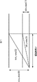
ビットレートに応じてVBVバッファの使用可能範囲が制御される場合の、VBVバッファの最大容量、ビットレート、および、符号化遅延について、図1を用いて説明する。 The maximum capacity, bit rate, and encoding delay of the VBV buffer when the usable range of the VBV buffer is controlled according to the bit rate will be described with reference to FIG.
VBVバッファの最大容量がvbv_size(0)であり、符号化遅延をτとするときのビットレートがbit_rate(0)である場合、次の式(1)が満たされる。 When the maximum capacity of the VBV buffer is vbv_size (0) and the bit rate when the encoding delay is τ is bit_rate (0), the following equation (1) is satisfied.
τ=vbv_size(0)/bit_rate(0)・・・(1) τ = vbv_size (0) / bit_rate (0) (1)
シームレスビットレート変更を行なうことのできる条件は、ビットレート変更後の遅延時間が常にτ以下となることであり、bit_rate(0)より低いビットレートbit_rate(1)にビットレートが変更する際のVBVバッファ最大値vbv_size(1)は、次の式(2)を満たすようになされる。 The condition for changing the seamless bit rate is that the delay time after changing the bit rate is always τ or less, and the VBV when changing the bit rate to bit_rate (1) lower than bit_rate (0). The buffer maximum value vbv_size (1) is set so as to satisfy the following expression (2).
vbv_size(1)=bit_rate(1)×τ・・・(2) vbv_size (1) = bit_rate (1) x τ (2)
すなわち、図2に示されるように、ビットレートがbit_rate(0)からbit_rate(1)に変更される場合、VBVバッファの最大値は、vbv_size(0)からvbv_size(1)に変更され、ビットレートがbit_rate(1)からbit_rate(0)に変更される場合、VBVバッファの最大値は、vbv_size(1)からvbv_size(0)に変更される。 That is, as shown in FIG. 2, when the bit rate is changed from bit_rate (0) to bit_rate (1), the maximum value of the VBV buffer is changed from vbv_size (0) to vbv_size (1). Is changed from bit_rate (1) to bit_rate (0), the maximum value of the VBV buffer is changed from vbv_size (1) to vbv_size (0).
ここで、ビットレートが低ビットレートであるbit_rate(1)から、高ビットレートであるbit_rate(0)に変更される場合、図2のビットレート変更点Aにおいて、VBVバッファの占有量が少ないにもかかわらず、急にビットレートが高くなることにより、前のピクチャに基づいて符号化をするために、発生符号量が大きくなり、VBVアンダーフローが発生しやすくなる。このような場合、VBVアンダーフローを回避するために、デコーダでは、ピクチャスキップやマクロブロックスキップが行われてしまい、画質が劣化してしまう。 Here, when the bit rate is changed from bit_rate (1), which is a low bit rate, to bit_rate (0), which is a high bit rate, the VBV buffer occupies less at the bit rate change point A in FIG. However, since the bit rate suddenly increases, encoding is performed based on the previous picture, so that the amount of generated code increases and VBV underflow is likely to occur. In such a case, in order to avoid VBV underflow, the picture skip or macro block skip is performed in the decoder, and the image quality deteriorates.
本発明はこのような状況に鑑みてなされたものであり、ビットレートが変更された場合、特に、低レートから高レートに変更された場合においても、VBVアンダーフローが発生しないように、レート制御を行うことができるようにするものである。 The present invention has been made in view of such a situation, and rate control is performed so that VBV underflow does not occur even when the bit rate is changed, particularly when the rate is changed from a low rate to a high rate. Is to be able to do.
本発明の符号化装置は、フレーム画像データのビットレートを検出する第1の検出手段と、第1の検出手段による検出結果を基に、ビットレートが変更された場合、復号装置の入力バッファに対応する仮想バッファの初期バッファ容量を調整し、仮想バッファの初期バッファ容量の値を用いて、量子化インデックスデータを決定する決定手段と、決定手段により決定された量子化インデックスデータを基に、量子化を実行する量子化手段と、量子化手段により量子化された量子化係数データを符号化する符号化手段とを備えることを特徴とする。 The encoding device according to the present invention includes a first detection unit that detects a bit rate of frame image data and a detection result obtained by the first detection unit. The initial buffer capacity of the corresponding virtual buffer is adjusted, and using the initial buffer capacity value of the virtual buffer, the quantization index data is determined, and the quantization index data determined by the determination means is used to determine the quantum index data. quantizing means for performing a reduction, characterized in that Ru and an encoding means for encoding the quantized coefficient data quantized by the quantization means.
決定手段には、バッファ占有量を更に検出させるようにすることができ、ビットレートが変更された場合、第1の検出手段により検出された変更前の第1のビットレート、および、変更後の第2のビットレート、並びに、検出されたビットレート変更時のバッファ占有量を基に、仮想バッファの初期バッファ容量の値を算出して、初期バッファ容量を調整させるようにすることができる。 The determination unit may further detect the buffer occupancy, and when the bit rate is changed, the first bit rate before the change detected by the first detection unit, and the post-change Based on the second bit rate and the detected buffer occupation amount when the bit rate is changed, the initial buffer capacity value of the virtual buffer can be calculated to adjust the initial buffer capacity.
フレーム画像データの符号化難易度を検出する第2の検出手段を更に備えさせるようにすることができ、決定手段には、バッファ占有量を更に検出させるようにすることができ、ビットレートが変更された場合、第1の検出手段により検出された変更前の第1のビットレート、および、変更後の第2のビットレート、検出されたビットレート変更時のバッファ占有量、並びに、第2の検出手段により検出されたフレーム画像データの符号化難易度を基に、仮想バッファの初期バッファ容量の値を算出して、初期バッファ容量を調整させるようにすることができる。 Second detection means for detecting the encoding difficulty level of the frame image data can be further provided, and the determining means can further detect the buffer occupancy, and the bit rate can be changed. The first bit rate before the change detected by the first detection means, the second bit rate after the change, the buffer occupation amount when the detected bit rate is changed, and the second bit rate The initial buffer capacity value can be adjusted by calculating the initial buffer capacity value of the virtual buffer based on the encoding difficulty level of the frame image data detected by the detecting means.
フレーム画像データの符号化難易度を検出する第2の検出手段を更に備えさせるようにすることができ、決定手段には、バッファ占有量を更に検出させるようにすることができ、ビットレートが変更された場合、第2の検出手段により検出されたフレーム画像データの符号化難易度を所定の閾値と比較させるようにすることができ、符号化難易度が所定の閾値よりも高かったとき、第1の検出手段により検出された変更前の第1のビットレート、および、変更後の第2のビットレート、検出されたビットレート変更時のバッファ占有量、並びに、第2の検出手段により検出されたフレーム画像データの符号化難易度を基に、仮想バッファの初期バッファ容量の値を算出して、初期バッファ容量を調整させるようにすることができる。 Second detection means for detecting the encoding difficulty level of the frame image data can be further provided, and the determining means can further detect the buffer occupancy, and the bit rate can be changed. In this case, the encoding difficulty level of the frame image data detected by the second detection means can be compared with a predetermined threshold value. When the encoding difficulty level is higher than the predetermined threshold value, The first bit rate before the change detected by the first detection means, the second bit rate after the change, the buffer occupation amount when the detected bit rate is changed, and the second bit rate detected by the second detection means The initial buffer capacity value can be adjusted by calculating the initial buffer capacity value of the virtual buffer based on the degree of difficulty of encoding the frame image data.
本発明の符号化装置においては、フレーム画像データのビットレートが検出され、ビットレートが変更された場合、復号装置の入力バッファに対応する仮想バッファの初期バッファ容量が調整され、仮想バッファの初期バッファ容量の値を用いて、量子化インデックスデータが決定され、量子化インデックスデータを基に、量子化が実行され、量子化係数データが符号化される。 In the encoding device of the present invention, when the bit rate of the frame image data is detected and the bit rate is changed, the initial buffer capacity of the virtual buffer corresponding to the input buffer of the decoding device is adjusted , and the initial buffer of the virtual buffer is adjusted. Quantization index data is determined using the capacity value, quantization is performed based on the quantization index data, and quantization coefficient data is encoded.
本発明の符号化方法は、ビットレートに関する情報を取得するビットレート情報取得ステップと、ビットレート情報取得ステップの処理により取得されたビットレートに関する情報を基に、ビデオデータを構成するピクチャのビットレートが変更されたか否かを判断する判断ステップと、判断ステップの処理により、ビットレートが変更されたと判断された場合、復号装置の入力バッファに対応する仮想バッファの初期バッファ容量を調整する調整ステップとを含むことを特徴とする。 The encoding method of the present invention includes a bit rate information acquisition step for acquiring information about a bit rate, and a bit rate of a picture constituting video data based on the information about the bit rate acquired by the processing of the bit rate information acquisition step. A determination step for determining whether the bit rate has been changed by the processing of the determination step, and an adjustment step for adjusting the initial buffer capacity of the virtual buffer corresponding to the input buffer of the decoding device ; It is characterized by including.
本発明のプログラムは、ビットレートに関する情報を取得するビットレート情報取得ステップと、ビットレート情報取得ステップの処理により取得されたビットレートに関する情報を基に、ビデオデータを構成するピクチャのビットレートが変更されたか否かを判断する判断ステップと、判断ステップの処理により、ビットレートが変更されたと判断された場合、復号装置の入力バッファに対応する仮想バッファの初期バッファ容量を調整する調整ステップとを含むことを特徴とする。 According to the program of the present invention, the bit rate of a picture constituting video data is changed based on the bit rate information acquisition step for acquiring information on the bit rate and the information on the bit rate acquired by the processing of the bit rate information acquisition step. A determination step for determining whether or not the bit rate has been changed by the processing of the determination step, and an adjustment step for adjusting the initial buffer capacity of the virtual buffer corresponding to the input buffer of the decoding device. It is characterized by that.
本発明の第1の符号化方法およびプログラムにおいては、ビットレートに関する情報が取得され、ビットレートに関する情報を基に、ビデオデータを構成するピクチャのビットレートが変更されたか否かが判断され、ビットレートが変更されたと判断された場合、仮想バッファの初期バッファ容量が調整される。
本発明の第2の符号化装置は、画像データを符号化する際のビットレートが変更されたことを検出するビットレート変更検出手段と、ビットレート変更検出手段によりビットレートの変更が検出された場合に、復号手段の入力バッファに対応する仮想バッファの初期バッファ容量を調整する調整手段と、調整手段により調整された初期バッファ容量の値に基づいて、画像データを符号化する際の量子化インデックスデータを決定する決定手段と、決定手段により決定された量子化インデックスデータに基づいて、画像データを符号化する符号化手段とを備える。
調整手段には、ビットレート変更検出手段により検出されたビットレート変更時のバッファ占有量を基に、仮想バッファの初期バッファ容量の値を算出して、算出結果を用いて、初期バッファ容量を調整させるようにすることができる。
画像データの符号化難易度を検出する符号化難易度検出手段を更に備えさせるようにすることができ、調整手段には、符号化難易度検出手段により検出された符号化難易度を基に、仮想バッファの初期バッファ容量の値を算出して、算出結果を用いて、初期バッファ容量を調整させるようにすることができる。
画像データの符号化難易度を検出する符号化難易度検出手段を更に備えさせるようにすることができ、調整手段には、符号化難易度検出手段により検出された符号化難易度が所定の閾値よりも高い場合に、符号化難易度検出手段により検出された符号化難易度を基に、仮想バッファの初期バッファ容量の値を算出して、算出結果を用いて、初期バッファ容量を調整させるようにすることができる。
画像データの符号化難易度を検出する符号化難易度検出手段を更に備えさせるようにすることができ、調整手段には、符号化難易度検出手段により検出された符号化難易度が所定の閾値よりも高い場合に、ビットレート変更検出手段により検出されたビットレート変更時のバッファ占有量を基に、仮想バッファの初期バッファ容量の値を算出して、算出結果を用いて、初期バッファ容量を調整させるようにすることができる。
本発明の第2の符号化方法は、画像データを符号化する際のビットレートが変更されたことを検出し、ビットレートの変更が検出された場合に、復号部の入力バッファに対応する仮想バッファの初期バッファ容量を調整し、調整された初期バッファ容量の値に基づいて、画像データを符号化する際の量子化インデックスデータを決定し、決定された量子化インデックスデータに基づいて、画像データを符号化するステップを含む。
本発明の第2の符号化装置および方法においては、画像データを符号化する際のビットレートが変更されたことが検出され、ビットレートの変更が検出された場合に、復号における入力バッファに対応する仮想バッファの初期バッファ容量が調整され、調整された初期バッファ容量の値に基づいて、画像データを符号化する際の量子化インデックスデータが決定され、決定された量子化インデックスデータに基づいて、画像データが符号化される。
In the first encoding method and program of the present invention, information on the bit rate is acquired, and based on the information on the bit rate, it is determined whether or not the bit rate of the picture constituting the video data has been changed, and the bit If it is determined that the rate has changed, the initial buffer capacity of the virtual buffer is adjusted.
According to the second encoding device of the present invention, the bit rate change detecting means for detecting that the bit rate at the time of encoding the image data is changed, and the bit rate change detecting means detects the change in the bit rate. An adjustment unit that adjusts the initial buffer capacity of the virtual buffer corresponding to the input buffer of the decoding unit, and a quantization index for encoding the image data based on the value of the initial buffer capacity adjusted by the adjustment unit A determination unit configured to determine data; and an encoding unit configured to encode the image data based on the quantization index data determined by the determination unit.
The adjustment means calculates the initial buffer capacity value of the virtual buffer based on the buffer occupancy at the time of the bit rate change detected by the bit rate change detection means, and adjusts the initial buffer capacity using the calculation result. You can make it.
An encoding difficulty level detecting unit that detects the encoding difficulty level of the image data can be further provided, and the adjustment unit is based on the encoding difficulty level detected by the encoding difficulty level detecting unit. It is possible to calculate the initial buffer capacity value of the virtual buffer and adjust the initial buffer capacity using the calculation result.
An encoding difficulty level detection unit that detects the encoding difficulty level of the image data can be further provided, and the adjustment level of the adjustment level detected by the encoding difficulty level detection unit is a predetermined threshold value. The initial buffer capacity value of the virtual buffer is calculated based on the encoding difficulty level detected by the encoding difficulty level detection means, and the initial buffer capacity is adjusted using the calculation result. Can be.
An encoding difficulty level detection unit that detects the encoding difficulty level of the image data can be further provided, and the adjustment level of the adjustment level detected by the encoding difficulty level detection unit is a predetermined threshold value. If it is higher, the initial buffer capacity value of the virtual buffer is calculated based on the buffer occupancy at the time of the bit rate change detected by the bit rate change detection means, and the initial buffer capacity is calculated using the calculation result. It can be adjusted.
The second encoding method of the present invention detects that the bit rate at the time of encoding the image data has been changed, and if a change in the bit rate is detected, the virtual encoding corresponding to the input buffer of the decoding unit is detected. The initial buffer capacity of the buffer is adjusted, quantization index data for encoding the image data is determined based on the adjusted initial buffer capacity value, and the image data is determined based on the determined quantization index data. Encoding.
In the second encoding apparatus and method of the present invention, it is detected that the bit rate at the time of encoding image data has been changed, and when a change in the bit rate is detected, the input buffer for decoding is supported. The initial buffer capacity of the virtual buffer is adjusted, and based on the adjusted initial buffer capacity value, quantization index data for encoding the image data is determined, and based on the determined quantization index data, Image data is encoded.
本発明によれば、フレーム画像データを符号化することができる。特に、ビットレートの変更が検出された場合、必要に応じて、前記仮想バッファの初期バッファ容量を調整するようにしたので、VBVバッファアンダーフローを防ぐことができ、画像の劣化を防止することができる。
また、他の本発明によれば、画像データを符号化することができ、特に、ビットレートの変更が検出された場合に、復号手段の入力バッファに対応する仮想バッファの初期バッファ容量を調整して、画像データを符号化する際の量子化インデックスデータを決定するようにしたので、VBVバッファアンダーフローを防ぐことができ、画像の劣化を防止することができる。
According to the present invention, frame image data can be encoded. In particular, when a change in the bit rate is detected, the initial buffer capacity of the virtual buffer is adjusted as necessary, so that VBV buffer underflow can be prevented and image deterioration can be prevented. it can.
According to another aspect of the present invention, image data can be encoded. In particular, when a change in bit rate is detected, an initial buffer capacity of a virtual buffer corresponding to an input buffer of a decoding unit is adjusted. Since the quantization index data for encoding image data is determined, VBV buffer underflow can be prevented and image degradation can be prevented.
以下に本発明の実施の形態を説明するが、特許請求の範囲に記載の発明の各手段および各ステップと以下の実施の形態との対応関係を明らかにするために、各手段および各ステップの後の括弧内に、対応する実施の形態(但し一例)を付加して本発明の特徴を記述すると、次のようになる。但し勿論この記載は、各手段および各ステップを記載したものに限定することを意味するものではない。 Embodiments of the present invention will be described below. In order to clarify the correspondence between each means and each step of the invention described in the claims and the following embodiments, each means and each step will be described. The features of the present invention are described as follows by adding the corresponding embodiment (however, by way of example) within the parentheses. However, of course, this description does not mean that each means and each step are limited to those described.
請求項1に記載の符号化装置(例えば、図3の符号化装置1または図5の符号化装置41)は、フレーム画像データのビットレートを検出する第1の検出手段(例えば、図3または図5のビットレート取得部31)と、第1の検出手段による検出結果を基に、ビットレートが変更された場合、復号装置の入力バッファに対応する仮想バッファの初期バッファ容量を調整し、仮想バッファの初期バッファ容量の値を用いて、量子化インデックスデータを決定する決定手段(例えば、図3の仮想バッファ決定部32または図5の仮想バッファ決定部62)と、決定手段により決定された量子化インデックスデータを基に、量子化を実行する量子化手段(例えば、図3または図5の量子化部15)と、量子化手段により量子化された量子化係数データを符号化する符号化手段(例えば、図3または図5のVLC部16)とを備える。
The encoding device according to claim 1 (for example, the
請求項2に記載の符号化装置は、決定手段が、バッファ占有量を更に検出し、ビットレートが変更された場合、第1の検出手段により検出された変更前の第1のビットレート(例えば、式(3)におけるbit_rate(1))、および、変更後の第2のビットレート(例えば、式(3)におけるbit_rate(0))、並びに、検出されたビットレート変更時のバッファ占有量(例えば、式(3)におけるvbv_ocp)を基に、仮想バッファの初期バッファ容量の値を算出して、初期バッファ容量を調整することを特徴とする。
In the encoding device according to
請求項3に記載の符号化装置は、フレーム画像データの符号化難易度を検出する第2の検出手段(例えば、図5の画像難易度情報取得部61)を更に備え、決定手段は、バッファ占有量を更に検出し、ビットレートが変更された場合、第1の検出手段により検出された変更前の第1のビットレート(例えば、式(11)におけるbit_rate(1))、および、変更後の第2のビットレート(例えば、式(11)におけるbit_rate(0))、検出されたビットレート変更時のバッファ占有量(例えば、式(11)におけるvbv_ocp)、並びに、第2の検出手段により検出されたフレーム画像データの符号化難易度(例えば、式(11)におけるdiff_info)を基に、仮想バッファの初期バッファ容量の値を算出して、初期バッファ容量を調整することを特徴とする。
The encoding apparatus according to
請求項4に記載の符号化装置は、フレーム画像データの符号化難易度を検出する第2の検出手段(例えば、図5の画像難易度情報取得部61)を更に備え、決定手段は、バッファ占有量を更に検出し、ビットレートが変更された場合、第2の検出手段により検出されたフレーム画像データの符号化難易度(例えば、diff_info)を所定の閾値と比較し、符号化難易度が所定の閾値よりも高かったとき、第1の検出手段により検出された変更前の第1のビットレート(例えば、式(11)におけるbit_rate(1))、および、変更後の第2のビットレート(例えば、式(11)におけるbit_rate(0))、検出されたビットレート変更時のバッファ占有量(例えば、式(11)におけるvbv_ocp)、並びに、第2の検出手段により検出されたフレーム画像データの符号化難易度(例えば、式(11)におけるdiff_info)を基に、仮想バッファの初期バッファ容量の値を算出して、初期バッファ容量を調整することを特徴とする。
The encoding device according to claim 4 further includes second detection means (for example, the image difficulty level
請求項5に記載の符号化方法は、ビットレートに関する情報を取得するビットレート情報取得ステップ(例えば、図4のステップS1、図6のステップS21、または、図7のステップS41)と、ビットレート情報取得ステップの処理により取得されたビットレートに関する情報を基に、ビデオデータを構成するピクチャのビットレートが変更されたか否かを判断する判断ステップ(例えば、図4のステップS2、図6のステップS22、または、図7のステップS42)と、判断ステップの処理により、復号装置の入力バッファに対応するビットレートが変更されたと判断された場合、仮想バッファの初期バッファ容量を調整する調整ステップ(例えば、図4のステップS4、図6のステップS24、または、図7のステップS46)とを含むことを特徴とする。 The encoding method according to claim 5 includes a bit rate information acquisition step (for example, step S1 in FIG. 4, step S21 in FIG. 6, or step S41 in FIG. 7) for acquiring information on the bit rate, Judgment step for judging whether or not the bit rate of the picture constituting the video data has been changed based on the information about the bit rate obtained by the processing of the information obtaining step (for example, step S2 in FIG. 4, step in FIG. 6) If it is determined that the bit rate corresponding to the input buffer of the decoding device has been changed by the processing of S22 or step S42 of FIG. 7 and the determination step, an adjustment step of adjusting the initial buffer capacity of the virtual buffer ( for example, Step S4 in FIG. 4, Step S24 in FIG. 6, or Step S46 in FIG. Characterized in that it contains.
また、請求項6に記載のプログラムにおいても、各ステップが対応する実施の形態(但し一例)は、請求項5に記載の符号化方法と同様である。 Also in the program according to claim 6, the embodiment (however, an example) to which each step corresponds is the same as the encoding method according to claim 5.
以下、図を参照して、本発明の実施の形態について説明する。 Hereinafter, embodiments of the present invention will be described with reference to the drawings.
図3は、本発明を適用した符号化装置1の構成を示すブロック図である。
FIG. 3 is a block diagram showing a configuration of the
画像並べ替え部11は、順次入力されるビデオデータの各フレーム画像を、必要に応じて並べ替えたり、16画素×16ラインの輝度信号、および輝度信号に対応する色差信号によって構成されるマクロブロックに分割したマクロブロックデータを生成して、演算部12、および、動き検出部13に供給する。
The
動き検出部13は、マクロブロックデータの入力を受け、各マクロブロックの動きベクトルを、マクロブロックデータ、および、ビデオメモリ21に記憶されている参照画像データを基に算出し、動きベクトルデータとして、動き補償部20に送出する。
The
演算部12は、画像並べ替え部11から供給されたマクロブロックデータについて、各マクロブロックの画像タイプに基づいた動き補償を行う。具体的には、演算部12は、Iピクチャに対してはイントラモードで動き補償を行い、Pピクチャに対しては、順方向予測モードで動き補償を行い、Bピクチャに対しては、双方向予測モードで動き補償を行うようになされている。
The
ここでイントラモードとは、符号化対象となるフレーム画像をそのまま伝送データとする方法であり、順方向予測モードとは、符号化対象となるフレーム画像と過去参照画像との予測残差を伝送データとする方法であり、双方向予測モードとは、符号化対象となるフレーム画像と、過去と将来の参照画像との予測残差を伝送データとする方法である。 Here, the intra mode is a method in which a frame image to be encoded is used as transmission data as it is, and the forward prediction mode is a prediction residual between a frame image to be encoded and a past reference image as transmission data. The bidirectional prediction mode is a method in which transmission residuals are prediction residuals between a frame image to be encoded and past and future reference images.
まず、マクロブロックデータがIピクチャであった場合、マクロブロックデータはイントラモードで処理される。すなわち、演算部12は、入力されたマクロブロックデータのマクロブロックを、そのまま演算データとしてDCT(Discrete Cosine Transform :離散コサイン変換)部14に送出する。DCT部14は、入力された演算データに対しDCT変換処理を行うことによりDCT係数化し、これをDCT係数データとして、量子化部15に送出する。
First, when the macroblock data is an I picture, the macroblock data is processed in the intra mode. That is, the
量子化部15は、量子化制御部23の仮想バッファ決定部32から供給される量子化値Qに基づいて、入力されたDCT係数データに対して量子化処理を行い、量子化DCT係数データとしてVLC(Variable Length Code;可変長符号化)部16および逆量子化部17に送出する。ここで、量子化部15は、仮想バッファ決定部32から供給される量子化値Qに応じて、量子化処理における量子化ステップサイズを調整することにより、発生する符号量を制御するようになされている。
The
逆量子化部17に送出された量子化DCT係数データは、量子化部15と同じ量子化ステップサイズによる逆量子化処理を受け、DCT係数データとして、IDCT(Inverse Discreet Cosine Transform;逆離散コサイン変換)部18に送出される。IDCT部18は、供給されたDCT係数データに逆DCT処理を施し、生成された演算データは、演算部19に送出され、参照画像データとしてビデオメモリ21に記憶される。
The quantized DCT coefficient data sent to the
そして、演算部12は、マクロブロックデータがPピクチャであった場合、マクロブロックデータについて、順方向予測モードよる動き補償処理を行い、Bピクチャであった場合、マクロブロックデータについて、双方向予測モードによる動き補償処理を行う。
Then, when the macroblock data is a P picture, the
動き補償部20は、ビデオメモリ21に記憶されている参照画像データを、動きベクトルデータに応じて動き補償し、順方向予測画像データ、または、双方向予測画像データを算出する。演算部12は、マクロブロックデータについて、動き補償部20より供給される順方向予測画像データ、または、双方向予測画像データを用いて減算処理を実行する。
The
すなわち、順方向予測モードにおいて、動き補償部20は、ビデオメモリ21の読み出しアドレスを、動きベクトルデータに応じてずらすことによって、参照画像データを読み出し、これを順方向予測画像データとして演算部12および演算部19に供給する。演算部12は、供給されたマクロブロックデータから、順方向予測画像データを減算して、予測残差としての差分データを得る。そして、演算部12は、差分データをDCT部14に送出する。
That is, in the forward prediction mode, the
演算部19には、動き補償部20より順方向予測画像データが供給されており、演算部19は、IDCT部18から供給された演算データに、順方向予測画像データを加算することにより、参照画像データを局部再生し、ビデオメモリ21に出力して記憶させる。
The forward prediction image data is supplied from the
また、双方向予測モードにおいて、動き補償部20は、ビデオメモリ21の読み出しアドレスを、動きベクトルデータに応じてずらすことによって、参照画像データを読み出し、これを双方向予測画像データとして演算部12および演算部19に供給する。演算部12は、供給されたマクロブロックデータから、双方向予測画像データを減算して、予測残差としての差分データを得る。そして、演算部12は、差分データをDCT部14に送出する。
In the bidirectional prediction mode, the
演算部19には、動き補償部20より双方向予測画像データが供給されており、演算部19は、IDCT部18から供給された演算データに、双方向予測画像データを加算することにより、参照画像データを局部再生し、ビデオメモリ21に出力して記憶させる。
Bidirectional prediction image data is supplied to the
かくして、符号化装置1に入力された画像データは、動き補償予測処理、DCT処理および量子化処理を受け、量子化DCT係数データとして、VLC部16に供給される。VLC部16は、量子化DCT係数データに対し、所定の変換テーブルに基づく可変長符号化処理を行い、その結果得られる可変長符号化データをバッファ22に送出する。バッファ22は、供給された可変長符号化ストリームを所定の時間バッファリングした後、出力する。
Thus, the image data input to the
出力された可変長符号化ストリームは、例えば、必要に応じて、オーディオストリームや、他の映像ストリームと多重化されて、所定の処理により、分割されて、ヘッダなどが付加されることによりパケット化され、複数のパケットデータにより構成されるMPEGトランスポートストリームが、所定のデータ伝送路によって、伝送される。 The output variable length encoded stream is multiplexed with, for example, an audio stream or another video stream as necessary, divided by a predetermined process, and packetized by adding a header or the like. Then, an MPEG transport stream composed of a plurality of packet data is transmitted through a predetermined data transmission path.
量子化制御部23は、符号化装置1における量子化を制御するものである。ビットレート情報取得部31は、ビットレートの値、または、ビットレートの値を示す情報を取得し、仮想バッファ決定部32に供給する。仮想バッファ決定部32は、バッファ22に格納される可変長符号化データの蓄積状態を常時監視しており、ビットレートが変更されたか否かに基づいて、仮想バッファの初期バッファ容量の調整を実行する。仮想バッファ決定部32は、算出された仮想バッファの初期バッファ容量に基づいて、目標符号量を決定し、目標符号量を発生するための量子化ステップサイズを決定して、量子化部15に供給するようになされている。
The
図2を用いて説明したように、符号化装置1においては、ビットレートがbit_rate(0)からbit_rate(1)に変更される場合、VBVバッファの最大値は、vbv_size(0)からvbv_size(1)に変更され、ビットレートがbit_rate(1)からbit_rate(0)に変更される場合、VBVバッファの最大値は、vbv_size(1)からvbv_size(0)に変更される。
As described with reference to FIG. 2, in the
特に、ビットレートが低レートから高レートに変更された場合、ビットレートの変更の差分が大きく、レート変更時のバッファ占有量が小さいほど、VBVアンダーフローが起こりやすい状態となるため、仮想バッファ決定部32は、ビットレートの変更を検出した場合、次の式(3)を用いて仮想バッファの初期バッファ容量を決定し、目標符号量を発生するための量子化ステップサイズを決定して、量子化部15に供給するようになされている。
In particular, when the bit rate is changed from a low rate to a high rate, the difference between the bit rate changes is larger, and the smaller the buffer occupancy at the rate change, the more likely VBV underflow occurs. When the change in the bit rate is detected, the
d’(0)=d(0)×k1×|bit_rate(1)−bit_rate(0)|/vbv_ocp・・・(3) d ′ (0) = d (0) × k1 × | bit_rate (1) −bit_rate (0) | / vbv_ocp (3)
ただし、式(3)において、k1は、経験的、または実験的に求められる所定の定数であり、bit_rate(1)は、変更後ビットレートであり、bit_rate(0)は、変更前ビットレートであり、vbv_ocpは、ビットレート変更時のVBV占有量である。 In Equation (3), k1 is a predetermined constant obtained empirically or experimentally, bit_rate (1) is the bit rate after change, and bit_rate (0) is the bit rate before change. Yes, vbv_ocp is the VBV occupation amount when the bit rate is changed.
また、仮想バッファ決定部32は、ビットレートの変更を検出しなかった場合、従来どおり量子化を制御する。すなわち、仮想バッファ決定部32は、ビットレートに対応するVBVバッファサイズおよびバッファ占有量情報に基づいて、目標発生符号量よりも実際に発生したマクロブロックの発生符号量が多いとき、発生符号量を減らすために量子化ステップサイズを大きくし、また目標発生符号量よりも実際の発生符号量が少ないとき、発生符号量を増やすために量子化ステップサイズを小さくするようになされている。
Further, when the virtual
すなわち、仮想バッファ決定部32は、デコーダ側に設けられたVBVバッファに格納された可変長符号化データの蓄積状態の推移を想定することにより、仮想バッファのバッファ占有量を求めて、量子化値Qを算出し、これを量子化部15に供給する。
That is, the virtual
j番目のマクロブロックにおける仮想バッファのバッファ占有量d(j)は、次の式(4)によって表され、また、j+1番目のマクロブロックにおける仮想バッファのバッファ占有量d(j+1)は、次の式(5)によって表され、(4)式から(5)式を減算することにより、j+1番目のマクロブロックにおける仮想バッファのバッファ占有量d(j+1)は、次の式(6)として表される。 The buffer occupancy d (j) of the virtual buffer in the jth macroblock is expressed by the following equation (4), and the buffer occupancy d (j + 1) of the virtual buffer in the j + 1th macroblock is The buffer occupation amount d (j + 1) of the virtual buffer in the j + 1-th macroblock is expressed as the following equation (6) by subtracting the equation (5) from the equation (4). The
d(j)=d(0)+B(j−1)−{T×(j−1)/MBcnt}・・・(4) d (j) = d (0) + B (j−1) − {T × (j−1) / MBcnt} (4)
ここで、d(0)は初期バッファ容量、B(j)は、j番目のマクロブロックにおける符号化発生ビット数、MBcntは、ピクチャ内のマクロブロック数、そして、Tは、ピクチャ単位の目標発生符号量である。 Here, d (0) is the initial buffer capacity, B (j) is the number of encoding generation bits in the j-th macroblock, MBcnt is the number of macroblocks in the picture, and T is the target generation in units of pictures. Code amount.
d(j+1)=d(0)+B(j)−(T×j)/MBcnt・・・(5) d (j + 1) = d (0) + B (j) − (T × j) / MBcnt (5)
d(j+1)=d(j)+{B(j)−B(j−1)}−T/MBcnt・・・(6) d (j + 1) = d (j) + {B (j) -B (j-1)}-T / MBcnt (6)
したがって、仮想バッファ決定部32は、バッファ占有量d(j+1)、および、式(7)に示される定数rを、式(8)に代入することにより、マクロブロック(j+1)の量子化インデックスデータQ(j+1)を算出し、これを量子化部15に供給する。
Therefore, the virtual
r=(2×br)/pr ・・・(7)
Q(j+1)=d(j+1)×(31/r) ・・・(8)
ここで、brは、ビットレートであり、prは、ピクチャレートである。
r = (2 × br) / pr (7)
Q (j + 1) = d (j + 1) × (31 / r) (8)
Here, br is a bit rate and pr is a picture rate.
量子化部15は、量子化値Qに基づいて、次のマクロブロックにおける量子化ステップサイズを決定し、量子化ステップサイズによってDCT係数データを量子化する。
The
これにより、量子化部15は、1つ前のピクチャにおける実際の発生符号量に基づいて算出された、次のピクチャの目標発生符号量にとって最適な量子化ステップサイズによって、DCT係数データを量子化することができる。
As a result, the
かくして、量子化部15では、バッファ22のデータ占有量に応じて、バッファ22がオーバーフローまたはアンダーフローしないように量子化し得るとともに、デコーダ側のVBVバッファがオーバーフロー、またはアンダーフローしないように量子化した量子化DCT係数データを生成することができる。
Thus, the
図2を用いて説明した従来の処理においては、VBVバッファの最大値が、遅延時間τとビットレートの積によって決められるようになされたが、このようにした場合、特に、ビットレートが低レートから高レートに変更されるとき、ビットレートの変更の差分が大きく、レート変更時のバッファ占有量が小さいほど、VBVアンダーフローが起こりやすい状態となってしまう。このような場合、VBVアンダーフローを防ぐためには、ビットレートの変更を検出して、上述した式(3)を用いて仮想バッファの初期バッファ容量を調整する必要がある。 In the conventional processing described with reference to FIG. 2, the maximum value of the VBV buffer is determined by the product of the delay time τ and the bit rate. In this case, the bit rate is particularly low. When changing from a high rate to a high rate, the difference in bit rate change is larger, and the smaller the buffer occupancy at the rate change, the more likely VBV underflow occurs. In such a case, in order to prevent VBV underflow, it is necessary to detect a change in the bit rate and adjust the initial buffer capacity of the virtual buffer using the above-described equation (3).
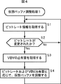
図4のフローチャートを参照して、図3の符号化装置1において実行される仮想バッファ調整処理1について説明する。
With reference to the flowchart of FIG. 4, the virtual
ステップS1において、ビットレート情報取得部31は、ビットレート情報を取得して、仮想バッファ決定部32に供給する。ビットレート情報は、ビットレートそのものの数値データあっても、ビットレートを示す対応する情報であっても良い。ビットレート情報取得部31は、外部の装置からビットレート情報を取得するようにしても良いし、ビットレート情報がビデオデータに多重化されている場合、ビデオデータからビットレート情報を抽出するようにしても良い。
In
ステップS2において、仮想バッファ決定部32は、供給されたビットレート情報を基に、ビットレートが変更されたか否かを判断する。ステップS2において、ビットレートが変更されていないと判断された場合、仮想バッファの初期バッファ容量は調整されないので、処理は、ステップS1に戻り、それ以降の処理が繰り返される。
In step S2, the virtual
ステップS2において、ビットレートが変更されたと判断された場合、ステップS3において、仮想バッファ決定部32は、VBVの占有量vbv_ocpを取得する。
When it is determined in step S2 that the bit rate has been changed, in step S3, the virtual
ステップS4において、仮想バッファ決定部32は、ステップS3で取得したVBVの占有量vbv_ocp、および、ステップS1において供給された変更前後のビットレートを基に、式(3)により、仮想バッファの初期バッファ容量d’(0)を算出して、仮想バッファの初期バッファ容量を、ビットレートおよびVBV占有量に応じた値に調整し、処理は、ステップS1に戻り、それ以降の処理が繰り返される。
In step S4, the virtual
このような処理により、ビットレートが変更されたときに、ビットレートおよびVBV占有量に応じた値となるように仮想バッファの初期バッファ容量を調整して、VBVアンダーフローの恐れがある場合には、発生符号量を抑制することができるようにしたので、ビットレートの変更の差分が大きく、レート変更時のバッファ占有量が小さくても、VBVアンダーフローの発生を未然に防ぐことにより、ピクチャスキップやマクロブロックスキップなどの発生による画質劣化を防止することができる。 If there is a risk of VBV underflow by adjusting the initial buffer capacity of the virtual buffer so that it becomes a value according to the bit rate and VBV occupation amount when the bit rate is changed by such processing Since the amount of generated code can be suppressed, even if the difference in bit rate change is large and the buffer occupancy at the time of rate change is small, VBV underflow can be prevented in advance, thereby skipping pictures And image quality deterioration due to occurrence of macroblock skip or the like can be prevented.
なお、符号化装置1において、例えば、TM5(Test Model 5)のように、仮想バッファをピクチャタイプ別に管理しているような場合、仮想バッファ決定部32は、ビットレート変更後に最初に現れる各ピクチャタイプにおいて、仮想バッファの初期バッファ容量を調整する。
In the
また、上述した処理においては、ステップS2において、ビットレートが高レートから低レートへ変更されたことが検出された場合であっても、低レートから高レートへ変更されたことが検出された場合であっても、ビットレートおよびVBV占有量に応じて、仮想バッファの初期バッファ容量を調整するものとして説明したが、VBVアンダーフローが発生しやすいのは、ビットレートが低レートから高レートへ変更されたときであるので、ビットレートが低レートから高レートへ変更されたときのみ、ビットレート、および、VBV占有量に応じて、仮想バッファの初期バッファ容量を調整するものとしてもよい。なお、ビットレートが高レートから低レートに変更されたときに仮想バッファの初期バッファ容量の調整を行うようにしても、仮想バッファの初期バッファ容量の調整を行わないときと比較して、画質劣化を防止することができるので、必要に応じて、ビットレートが高レートから低レートに変更されたときのみに仮想バッファの初期バッファ容量の調整を行うようにしてもよい。 In the above-described processing, even if it is detected in step S2 that the bit rate has been changed from the high rate to the low rate, it is detected that the bit rate has been changed from the low rate to the high rate. Even so, it was explained that the initial buffer capacity of the virtual buffer is adjusted according to the bit rate and VBV occupancy, but VBV underflow is likely to occur because the bit rate is changed from low rate to high rate Therefore, the initial buffer capacity of the virtual buffer may be adjusted according to the bit rate and the VBV occupation amount only when the bit rate is changed from the low rate to the high rate. Note that even if the initial buffer capacity of the virtual buffer is adjusted when the bit rate is changed from the high rate to the low rate, the image quality deteriorates compared with the case where the initial buffer capacity of the virtual buffer is not adjusted. If necessary, the initial buffer capacity of the virtual buffer may be adjusted only when the bit rate is changed from the high rate to the low rate.
ところで、符号化対象ピクチャが、符号化に容易な画像である場合、符号発生量は大きくならないため、VBVバッファのアンダーフローが起こる可能性がほとんどないにもかかわらず、仮想バッファの初期バッファ容量を調整して符号発生量を抑制してしまった場合、必要以上に画像が劣化してしまう。 By the way, if the picture to be encoded is an image that is easy to encode, the amount of code generation does not increase, so the initial buffer capacity of the virtual buffer is reduced even though there is almost no possibility of underflow of the VBV buffer. If the code generation amount is suppressed by adjustment, the image is deteriorated more than necessary.
したがって、画像の符号化難易度を検出することにより、ビットレートおよびVBV占有量に加えて、符号化難易度に応じた仮想バッファの初期バッファ容量を算出するようにしたり、符号化難易度が所定の値よりも低い場合においては、仮想バッファの初期バッファ容量の調整を行わないようにすることにより、符号化に容易な画像において、必要以上に画像を劣化させることを防止することが可能となる。 Therefore, by detecting the encoding difficulty level of the image, in addition to the bit rate and VBV occupation amount, the initial buffer capacity of the virtual buffer corresponding to the encoding difficulty level is calculated, or the encoding difficulty level is predetermined. In the case where the value is lower than the above value, it is possible to prevent the image from being deteriorated more than necessary in an image that is easy to encode by not adjusting the initial buffer capacity of the virtual buffer. .
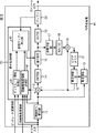
図5は、ビットレート、VBV占有量、および、符号化難易度に応じて、仮想バッファの初期バッファ容量を調整することができる符号化装置41の構成を示すブロック図である。
FIG. 5 is a block diagram illustrating a configuration of the
なお、図3における場合と対応する部分には同一の符号を付してあり、その説明は適宜省略する。すなわち、図5の符号化装置41は、量子化制御部23に代わって、量子化制御部51が設けられている以外は、図3を用いて説明した符号化装置1と同様の構成を有するものであり、量子化制御部51は、仮想バッファ決定部32に代わって、仮想バッファ決定部62が設けられ、新たに、画像難易度情報取得部61が設けられている以外は、図1の量子化制御部23と同様の構成を有するものである。
Note that portions corresponding to those in FIG. 3 are denoted by the same reference numerals, and description thereof will be omitted as appropriate. That is, the
画像難易度情報取得部61は、イントラAC(IntraAC)、またはME残差情報などの画像難易度情報を取得または算出し、仮想バッファ決定部62に供給する。
The image difficulty level
これらの画像難易度情報が供給されるビデオデータに含まれている場合、画像難易度情報取得部61は、ビデオデータから、画像難易度情報抽出する。また、画像難易度情報は、他の装置から供給されるものであっても良い。
When the image difficulty level information is included in the supplied video data, the image difficulty level
なお、画像難易度情報がME残差である場合、ME残差は、動き検出をするときに得られる情報であるので、画像難易度情報は、演算部12から供給されるものとしても良い。ME残差とは、ピクチャ単位で算出されるものであり、1つ前のピクチャと次のピクチャにおける輝度の差分値の合計値である。
When the image difficulty level information is an ME residual, the ME residual is information obtained when motion is detected, and thus the image difficulty level information may be supplied from the
また、画像難易度情報がイントラACである場合、画像難易度情報取得部61は、画像並べ替え部11から供給されるマクロブロックデータを基に、イントラACを算出するようにしても良い。
When the image difficulty level information is intra AC, the image difficulty level
イントラACは、MPEG方式におけるDCT処理単位のDCTブロックごとの映像データとの分散値の総和として定義されるパラメータであって、映像の複雑さを指標し、映像の絵柄の難しさおよび圧縮後のデータ量と相関性を有する。すなわち、イントラACとは、DCTブロック単位で、それぞれの画素の画素値から、ブロック毎の画素値の平均値を引いたものの絶対値和の、画面内における総和である。イントラACは、次の式(9)で示される。 Intra AC is a parameter defined as the sum of the variance values of video data for each DCT block in the DCT processing unit in the MPEG system, and indicates the complexity of the video, the difficulty of the picture design and the compression Correlate with data volume. In other words, the intra AC is the sum in the screen of the absolute value sum of the pixel value of each pixel minus the average value of the pixel values for each block in DCT block units. The intra AC is expressed by the following equation (9).

また、式(9)において、式(10)が成り立つ。
仮想バッファ決定部62は、ビットレートの変更を検出した場合、次の式(11)を用いて仮想バッファの初期バッファ容量を決定し、目標符号量を発生するための量子化ステップサイズを決定して、量子化部15に供給するようになされている。
When detecting a change in the bit rate, the virtual
d”(0)=d(0)×k2×diff_info×|bit_rate(1)−bit_rate(0)|/vbv_ocp
・・・(11)
d ”(0) = d (0) × k2 × diff_info × | bit_rate (1) −bit_rate (0) | / vbv_ocp
(11)
ただし、式(11)において、k2は、経験的、または実験的に求められる所定の定数であり、diff_infoは、画像難易度であり、bit_rate(1)は、変更後ビットレートであり、bit_rate(0)は、変更前ビットレートであり、vbv_ocpは、ビットレート変更時のVBV占有量である。 In Equation (11), k2 is a predetermined constant obtained empirically or experimentally, diff_info is the image difficulty level, bit_rate (1) is the changed bit rate, bit_rate ( 0) is the pre-change bit rate, and vbv_ocp is the VBV occupation amount when the bit rate is changed.
または、仮想バッファ決定部62は、ビットレートの変更を検出した場合、画像難易度を経験的、または実験的に求められる所定の閾値と比較し、画像難易度が所定の閾値より大きい場合(所定の値よりも符号化難易度が高い場合)にのみ、式(11)を基に、仮想バッファの初期バッファ容量を決定し、目標符号量を発生するための量子化ステップサイズを決定して、量子化部15に供給するようにしてもよい。
Alternatively, when detecting a change in the bit rate, the virtual
そして、仮想バッファ決定部62は、ビットレートの変更を検出しない場合、従来と同様のレート制御を行い、量子化部15の量子化処理を制御する。
When the virtual
次に、図6のフローチャートを参照して、図5の符号化装置41において実行される仮想バッファ調整処理2について説明する。
Next, the virtual
ステップS21において、ビットレート情報取得部31は、ビットレート情報を取得して、仮想バッファ決定部62に供給する。ビットレート情報は、ビットレートそのものの数値データあっても、ビットレートを示す対応する情報であっても良い。ビットレート情報取得部31は、外部の装置からビットレート情報を取得するようにしても良いし、ビットレート情報がビデオデータに多重化されている場合、ビデオデータからビットレート情報を抽出するようにしても良い。
In step S <b> 21, the bit rate
ステップS22において、仮想バッファ決定部62は、供給されたビットレート情報を基に、ビットレートが変更されたか否かを判断する。ステップS22において、ビットレートが変更されていないと判断された場合、仮想バッファの初期バッファ容量は調整されないので、処理は、ステップS21に戻り、それ以降の処理が繰り返される。
In step S22, the virtual
ステップS22において、ビットレートが変更されたと判断された場合、ステップS23において、仮想バッファ決定部62は、VBVの占有量vbv_ocpを取得し、画像難易度情報取得部61は、画像難易度情報diff_infoを取得して、仮想バッファ決定部62に供給する。
When it is determined in step S22 that the bit rate has been changed, in step S23, the virtual
ステップS24において、仮想バッファ決定部62は、ステップS23で取得したVBVの占有量vbv_ocpおよび画像難易度情報diff_info、並びに、ステップS21において供給された変更前後のビットレートを基に、式(11)により、仮想バッファの初期バッファ容量d”(0)を算出して、仮想バッファの初期バッファ容量を、ビットレート、VBV占有量、および、画像難易度に応じた値に調整し、処理は、ステップS21に戻り、それ以降の処理が繰り返される。
In step S24, the virtual
このような処理により、ビットレートが変更されたときに、ビットレートおよびVBV占有量に加えて、画像難易度に応じた値となるように仮想バッファの初期バッファ容量を調整して、発生符号量を必要に応じて抑制することができるようにしたので、ビットレートの変更の差分が大きく、レート変更時のバッファ占有量が小さくても、不必要に画像を劣化させることなく、VBVアンダーフローの発生を未然に防ぐことができ、ピクチャスキップやマクロブロックスキップなどの発生による画質劣化を防止することができる。 By such processing, when the bit rate is changed, in addition to the bit rate and VBV occupation amount, the initial buffer capacity of the virtual buffer is adjusted so as to become a value according to the image difficulty level, and the generated code amount VBV underflow can be suppressed without unnecessarily degrading the image even if the difference in bit rate change is large and the buffer occupancy at the rate change is small. Occurrence can be prevented in advance, and image quality deterioration due to occurrence of picture skip or macro block skip can be prevented.
また、上述した処理においては、ステップS22において、ビットレートが高レートから低レートへ変更されたことが検出された場合であっても、低レートから高レートへ変更されたことが検出された場合であっても、ビットレート、VBV占有量、および、画像難易度に応じて、仮想バッファの初期バッファ容量を調整するものとして説明したが、VBVアンダーフローが発生しやすいのは、ビットレートが低レートから高レートへ変更されたときであるので、ビットレートが低レートから高レートへ変更されたときのみ、ビットレート、VBV占有量、および、画像難易度に応じて、仮想バッファの初期バッファ容量を調整するものとしてもよい。なお、ビットレートが高レートから低レートに変更されたときに仮想バッファの初期バッファ容量の調整を行うようにしても、仮想バッファの初期バッファ容量の調整を行わないときと比較して画質劣化を防止することができるので、必要に応じて、ビットレートが高レートから低レートに変更されたときのみに、仮想バッファの初期バッファ容量の調整を行うようにしてもよい。 In the above-described processing, even when it is detected in step S22 that the bit rate has been changed from the high rate to the low rate, it is detected that the bit rate has been changed from the low rate to the high rate. Even so, although it has been described that the initial buffer capacity of the virtual buffer is adjusted according to the bit rate, VBV occupation amount, and image difficulty level, the bit rate is low because VBV underflow is likely to occur. Since the rate is changed from high rate to high rate, only when the bit rate is changed from low rate to high rate, the initial buffer capacity of the virtual buffer depends on the bit rate, VBV occupancy, and image difficulty It is good also as what adjusts. Even if the initial buffer capacity of the virtual buffer is adjusted when the bit rate is changed from the high rate to the low rate, the image quality is deteriorated as compared with the case where the initial buffer capacity of the virtual buffer is not adjusted. Therefore, if necessary, the initial buffer capacity of the virtual buffer may be adjusted only when the bit rate is changed from the high rate to the low rate.
次に、図7のフローチャートを参照して、図5の符号化装置41において実行される仮想バッファ調整処理3について説明する。
Next, the virtual
ステップS41において、ビットレート情報取得部31は、ビットレート情報を取得して、仮想バッファ決定部62に供給する。ビットレート情報は、ビットレートそのものの数値データあっても、ビットレートを示す対応する情報であっても良い。ビットレート情報取得部31は、外部の装置からビットレート情報を取得するようにしても良いし、ビットレート情報がビデオデータに多重化されている場合、ビデオデータからビットレート情報を抽出するようにしても良い。
In step S <b> 41, the bit rate
ステップS42において、仮想バッファ決定部62は、供給されたビットレート情報を基に、ビットレートが変更されたか否かを判断する。ステップS42において、ビットレートが変更されていないと判断された場合、仮想バッファの初期バッファ容量は調整されないので、処理は、ステップS41に戻り、それ以降の処理が繰り返される。ステップS42において、ビットレートが変更されたと判断された場合、ステップS43において、画像難易度情報取得部61は、画像難易度情報diff_infoを取得して、仮想バッファ決定部62に供給する。
In step S42, the virtual
ステップS44において、仮想バッファ決定部62は、ステップS43で供給された画像難易度情報diff_infoは、所定の閾値より高いか否かを判断する。ステップS44において、画像難易度情報diff_infoは、所定の閾値より低いと判断された場合、符号化に容易な画像は、VBVバッファのアンダーフローを起こさないので、仮想バッファの初期バッファ容量は調整されず、処理は、ステップS41に戻り、それ以降の処理が繰り返される。
In step S44, the virtual
ステップS44において、画像難易度情報diff_infoは、所定の閾値より高いと判断された場合、ステップS45において、仮想バッファ決定部62は、VBVの占有量vbv_ocpを取得する。
If it is determined in step S44 that the image difficulty level information diff_info is higher than a predetermined threshold value, in step S45, the virtual
ステップS46において、仮想バッファ決定部62は、ステップS45で取得したVBVの占有量vbv_ocp、ステップS43で供給された画像難易度情報diff_info、および、ステップS41において供給された変更前後のビットレートを基に、式(11)により、仮想バッファの初期バッファ容量d”(0)を算出して、仮想バッファの初期バッファ容量を、ビットレート、VBV占有量、および、画像難易度に応じた値に調整し、処理は、ステップS41に戻り、それ以降の処理が繰り返される。
In step S46, the virtual
このような処理により、ビットレートが変更されたときに、画像難易度の高い場合のみ、ビットレート、VBV占有量、および、画像難易度に応じた値となるように仮想バッファの初期バッファ容量を調整するようにしたので、符号化に容易な画像の画像劣化を防ぎつつ、発生符号量を必要に応じて抑制することができることができ、ビットレートの変更の差分が大きく、レート変更時のバッファ占有量が小さくても、VBVアンダーフローの発生を未然に防ぐことにより、ピクチャスキップやマクロブロックスキップなどの発生による画質劣化を防止することができる。 By such processing, when the bit rate is changed, only when the image difficulty level is high, the initial buffer capacity of the virtual buffer is set so that the value depends on the bit rate, the VBV occupation amount, and the image difficulty level. Since the adjustment is made, it is possible to suppress the amount of generated code as needed while preventing image deterioration of an image that is easy to encode, the difference in bit rate change is large, and the buffer at the time of rate change Even if the occupation amount is small, by preventing the occurrence of VBV underflow, it is possible to prevent image quality deterioration due to the occurrence of picture skip or macro block skip.
また、上述した処理においても、ステップS42において、ビットレートが高レートから低レートへ変更されたことが検出された場合であっても、低レートから高レートへ変更されたことが検出された場合であっても、ビットレート、VBV占有量、および、画像難易度に応じて、仮想バッファの初期バッファ容量を調整するものとして説明したが、VBVアンダーフローが発生しやすいのは、ビットレートが低レートから高レートへ変更されたときであるので、ビットレートが低レートから高レートへ変更されたときのみ、ビットレート、VBV占有量、および、画像難易度に応じて、仮想バッファの初期バッファ容量を調整するものとしてもよい。なお、ビットレートが高レートから低レートに変更されたときに仮想バッファの初期バッファ容量の調整を行うようにしても、仮想バッファの初期バッファ容量の調整を行わないときと比較して画質劣化を防止することができるので、必要に応じて、ビットレートが高レートから低レートに変更されたときのみに、仮想バッファの初期バッファ容量の調整を行うようにしてもよい。 In the processing described above, even when it is detected in step S42 that the bit rate has been changed from the high rate to the low rate, it has been detected that the bit rate has been changed from the low rate to the high rate. Even so, although it has been described that the initial buffer capacity of the virtual buffer is adjusted according to the bit rate, VBV occupation amount, and image difficulty level, the bit rate is low because VBV underflow is likely to occur. Since the rate is changed from high rate to high rate, only when the bit rate is changed from low rate to high rate, the initial buffer capacity of the virtual buffer depends on the bit rate, VBV occupancy, and image difficulty It is good also as what adjusts. Even if the initial buffer capacity of the virtual buffer is adjusted when the bit rate is changed from the high rate to the low rate, the image quality is deteriorated as compared with the case where the initial buffer capacity of the virtual buffer is not adjusted. Therefore, if necessary, the initial buffer capacity of the virtual buffer may be adjusted only when the bit rate is changed from the high rate to the low rate.
なお、符号化装置41においても、例えば、TM5(Test Model 5)のように、仮想バッファをピクチャタイプ別に管理しているような場合、仮想バッファ決定部62は、ビットレート変更後に最初に現れる各ピクチャタイプにおいて、仮想バッファの初期バッファ容量を調整する。
In the
また、本発明は、例えば、15フレームを、フレーム内符号化画像(Iピクチャ)、フレーム間順方向予測符号化画像(Pピクチャ)、もしくは、双方向予測符号化画像(Bピクチャ)の3つの画像タイプのうちのいずれの画像タイプとして処理するかを指定し、指定されたフレーム画像の画像タイプ(Iピクチャ、Pピクチャ、もしくは、Bピクチャ)に応じて、フレーム画像を符号化するような場合以外にも、ローディレイコーディングとして各フレーム画像を全てPピクチャとし、例えば、横45マクロブロック、縦24マクロブロックの画枠サイズの中でフレーム画像の上段から縦2マクロブロックおよび横45マクロブロック分の領域を1つのイントラスライス部分、他を全てインタースライス部分として設定するようにした場合にも適用可能である。また、ローディレイエンコードを行う場合においては、例えば、イントラスライス部分を縦1マクロブロック、横45マクロブロック分の領域とするなど、他の種々の大きさの領域で形成するようにしても良い。 In the present invention, for example, 15 frames are divided into three types of intra-frame encoded image (I picture), inter-frame forward prediction encoded image (P picture), or bidirectional predictive encoded image (B picture). When specifying which image type to process, and encoding a frame image according to the image type (I picture, P picture, or B picture) of the specified frame image In addition, as a low delay coding, each frame image is set to a P picture. For example, within the frame size of 45 macroblocks in the horizontal direction and 24 macroblocks in the vertical direction, from the upper part of the frame image to 2 macroblocks and 45 macroblocks in the horizontal direction. When the area is set as one intra slice part and all others are set as inter slice parts It can also be applied. In the case of performing low delay encoding, for example, the intra slice portion may be formed with regions of various other sizes, such as a region corresponding to one vertical macroblock and 45 horizontal macroblocks.
更に、本発明は、マクロブロックごとに予測符号化のタイプ(イントラマクロブロック、または、インターマクロブロック)を指定して符号化処理を行うような場合や、オールイントラなどの符号化を行う場合においても、適用することが可能である。 Furthermore, the present invention is applicable to the case where encoding processing is performed by specifying the type of predictive encoding (intra macroblock or inter macroblock) for each macroblock, or when encoding such as all-intra is performed. Can also be applied.
更に、上述の実施の形態においては、本発明を、MPEG方式によって圧縮符号化する符号化装置としての符号化装置1または符号化装置41に適用する場合について述べたが、本発明はこれに限らず、他の種々の画像圧縮方式による符号化装置に適用するようにしても良い。
Further, in the above-described embodiment, the case where the present invention is applied to the
また、独立した装置として構成される符号化装置1または符号化装置41のみならず、例えば、トランスコーダや編集装置などに含まれる、同様の構成を有する符号化部おいても、本発明は適用可能である。
Further, the present invention is applied not only to the
上述した一連の処理は、ハードウエアにより実行させることもできるが、ソフトウエアにより実行させることもできる。この場合、例えば、符号化装置1が実行する処理は、図8に示されるようなパーソナルコンピュータ101により構成される。
The series of processes described above can be executed by hardware, but can also be executed by software. In this case, for example, the processing executed by the
図8において、CPU(Central Processing Unit)111は、ROM(Read Only Memory)112に記憶されているプログラム、または記憶部118からRAM(Random Access Memory)113にロードされたプログラムに従って、各種の処理を実行する。RAM113にはまた、CPU111が各種の処理を実行する上において必要なデータなども適宜記憶される。
In FIG. 8, a CPU (Central Processing Unit) 111 performs various processes according to a program stored in a ROM (Read Only Memory) 112 or a program loaded from a
CPU111、ROM112、およびRAM113は、バス114を介して相互に接続されている。このバス114にはまた、入出力インタフェース115も接続されている。
The
入出力インタフェース115には、キーボード、マウスなどよりなる入力部116、ディスプレイやスピーカなどよりなる出力部117、ハードディスクなどより構成される記憶部118、モデム、ターミナルアダプタなどより構成される通信部119が接続されている。通信部119は、インターネットを含むネットワークを介しての通信処理を行う。
The input /
入出力インタフェース115にはまた、必要に応じてドライブ120が接続され、磁気ディスク121、光ディスク122、光磁気ディスク123、もしくは、半導体メモリ124などが適宜装着され、それらから読み出されたコンピュータプログラムが、必要に応じて記憶部118にインストールされる。
A
一連の処理をソフトウエアにより実行させる場合には、そのソフトウエアを構成するプログラムが、専用のハードウエアに組み込まれているコンピュータ、または、各種のプログラムをインストールすることで、各種の機能を実行することが可能な、例えば汎用のパーソナルコンピュータなどに、ネットワークや記録媒体からインストールされる。 When a series of processing is executed by software, a program constituting the software executes various functions by installing a computer incorporated in dedicated hardware or various programs. For example, a general-purpose personal computer is installed from a network or a recording medium.
この記録媒体は、図8に示されるように、装置本体とは別に、ユーザにプログラムを供給するために配布される、プログラムが記憶されている磁気ディスク121(フロッピディスクを含む)、光ディスク122(CD−ROM(Compact Disk−Read Only Memory),DVD(Digital Versatile Disk)を含む)、光磁気ディスク123(MD(Mini Disk)(商標)を含む)、もしくは半導体メモリ124などよりなるパッケージメディアにより構成されるだけでなく、装置本体に予め組み込まれた状態でユーザに供給される、プログラムが記憶されているROM112や、記憶部118に含まれるハードディスクなどで構成される。
As shown in FIG. 8, this recording medium includes a magnetic disk 121 (including a floppy disk) and an optical disk 122 (including a floppy disk) that are distributed to supply a program to a user separately from the apparatus main body. CD-ROM (compact disk-read only memory), DVD (including digital versatile disk), magneto-optical disk 123 (including MD (mini disk) (trademark)), or
なお、本明細書において、プログラムを記述するステップは、含む順序に沿って時系列的に行われる処理はもちろん、必ずしも時系列的に処理されなくとも、並列的もしくは個別に実行される処理をも含むものである。 In the present specification, the steps for describing a program include not only processes performed in time series in the order in which they are included, but also processes executed in parallel or individually, even though they are not necessarily processed in time series. Is included.
1 符号化装置, 11 画像並べ替え部, 12 演算部, 13 動き検出部, 14 DCT部, 15 量子化部, 16 VLC部, 17 逆量子化部, 18 IDCT部, 19 演算部, 20 動き補償部, 21 ビデオメモリ, 22 バッファ, 23 量子化制御部, 31 ビットレート情報取得部, 32 仮想バッファ決定部, 41 符号化装置, 51 量子化制御部, 61 画像難易度情報取得部
DESCRIPTION OF
Claims (12)
前記フレーム画像データのビットレートを検出する第1の検出手段と、
前記第1の検出手段による検出結果を基に、前記ビットレートが変更された場合、復号装置の入力バッファに対応する仮想バッファの初期バッファ容量を調整し、前記仮想バッファの初期バッファ容量の値を用いて、量子化インデックスデータを決定する決定手段と、
前記決定手段により決定された前記量子化インデックスデータを基に、量子化を実行する量子化手段と、
前記量子化手段により量子化された量子化係数データを符号化する符号化手段と
を備えることを特徴とする符号化装置。 In an encoding device for encoding frame image data,
First detection means for detecting a bit rate of the frame image data;
When the bit rate is changed based on the detection result by the first detection means, the initial buffer capacity of the virtual buffer corresponding to the input buffer of the decoding device is adjusted, and the value of the initial buffer capacity of the virtual buffer is set. Determining means for determining quantized index data,
Quantization means for performing quantization based on the quantization index data determined by the determination means;
Encoding device, characterized in that Ru and an encoding means for encoding the quantized coefficient data quantized by said quantization means.
ことを特徴とする請求項1に記載の符号化装置。 The determination means further detects the buffer occupancy, and when the bit rate is changed, the first bit rate before the change detected by the first detection means and the second bit after the change. 2. The initial buffer capacity is adjusted by calculating a value of an initial buffer capacity of the virtual buffer based on a rate and a detected buffer occupancy at the time of changing a bit rate. Encoding device.
前記決定手段は、バッファ占有量を更に検出し、前記ビットレートが変更された場合、前記第1の検出手段により検出された変更前の第1のビットレート、および、変更後の第2のビットレート、検出されたビットレート変更時のバッファ占有量、並びに、前記第2の検出手段により検出された前記フレーム画像データの符号化難易度を基に、前記仮想バッファの初期バッファ容量の値を算出して、前記初期バッファ容量を調整する
ことを特徴とする請求項1に記載の符号化装置。 A second detection means for detecting a degree of difficulty in encoding the frame image data;
The determination means further detects the buffer occupancy, and when the bit rate is changed, the first bit rate before the change detected by the first detection means and the second bit after the change. The initial buffer capacity value of the virtual buffer is calculated based on the rate, the buffer occupancy at the time of changing the bit rate, and the encoding difficulty level of the frame image data detected by the second detection means The encoding apparatus according to claim 1, wherein the initial buffer capacity is adjusted.
前記決定手段は、バッファ占有量を更に検出し、前記ビットレートが変更された場合、前記第2の検出手段により検出された前記フレーム画像データの符号化難易度を所定の閾値と比較し、前記符号化難易度が前記所定の閾値よりも高かったとき、前記第1の検出手段により検出された変更前の第1のビットレート、および、変更後の第2のビットレート、検出されたビットレート変更時のバッファ占有量、並びに、前記第2の検出手段により検出された前記フレーム画像データの符号化難易度を基に、前記仮想バッファの初期バッファ容量の値を算出して、前記初期バッファ容量を調整する
ことを特徴とする請求項1に記載の符号化装置。 A second detection means for detecting a degree of difficulty in encoding the frame image data;
The determining means further detects the buffer occupancy, and when the bit rate is changed, compares the encoding difficulty of the frame image data detected by the second detecting means with a predetermined threshold, When the encoding difficulty level is higher than the predetermined threshold, the first bit rate before the change detected by the first detection means, the second bit rate after the change, and the detected bit rate Based on the buffer occupancy at the time of change and the encoding difficulty level of the frame image data detected by the second detection means, a value of the initial buffer capacity of the virtual buffer is calculated, and the initial buffer capacity The encoding device according to claim 1, wherein the encoding device is adjusted.
前記ビットレートに関する情報を取得するビットレート情報取得ステップと、
前記ビットレート情報取得ステップの処理により取得された前記ビットレートに関する情報を基に、ビデオデータを構成するピクチャの前記ビットレートが変更されたか否かを判断する判断ステップと、
前記判断ステップの処理により、前記ビットレートが変更されたと判断された場合、復号装置の入力バッファに対応する仮想バッファの初期バッファ容量を調整する調整ステップと
を含むことを特徴とする符号化方法。 In an encoding method of an encoding device for encoding frame image data,
A bit rate information acquisition step of acquiring information on the bit rate;
Based on the information on the bit rate obtained by the processing of the bit rate information acquisition step, a determining step of determining whether the bit rate of pictures constituting the video data has changed,
An encoding method comprising: an adjustment step of adjusting an initial buffer capacity of a virtual buffer corresponding to an input buffer of a decoding device when it is determined that the bit rate has been changed by the processing of the determination step.
前記ビットレートに関する情報を取得するビットレート情報取得ステップと、
前記ビットレート情報取得ステップの処理により取得された前記ビットレートに関する情報を基に、ビデオデータを構成するピクチャの前記ビットレートが変更されたか否かを判断する判断ステップと、
前記判断ステップの処理により、前記ビットレートが変更されたと判断された場合、復号装置の入力バッファに対応する仮想バッファの初期バッファ容量を調整する調整ステップと
を含むことを特徴とするプログラム。 A program for causing a computer to execute processing for encoding frame image data,
A bit rate information acquisition step of acquiring information on the bit rate;
Based on the information on the bit rate obtained by the processing of the bit rate information acquisition step, a determining step of determining whether the bit rate of pictures constituting the video data has changed,
An adjustment step of adjusting an initial buffer capacity of a virtual buffer corresponding to an input buffer of the decoding device when it is determined that the bit rate has been changed by the processing of the determination step.
前記画像データを符号化する際のビットレートが変更されたことを検出するビットレート変更検出手段と、
前記ビットレート変更検出手段によりビットレートの変更が検出された場合に、復号手段の入力バッファに対応する仮想バッファの初期バッファ容量を調整する調整手段と、
前記調整手段により調整された前記初期バッファ容量の値に基づいて、前記画像データを符号化する際の量子化インデックスデータを決定する決定手段と、
前記決定手段により決定された前記量子化インデックスデータに基づいて、前記画像データを符号化する符号化手段と
を備える符号化装置。 In an encoding device for encoding image data,
A bit rate change detecting means for detecting that the bit rate at the time of encoding the image data is changed;
Adjusting means for adjusting the initial buffer capacity of the virtual buffer corresponding to the input buffer of the decoding means when a change in the bit rate is detected by the bit rate change detecting means;
Determining means for determining quantization index data for encoding the image data based on the value of the initial buffer capacity adjusted by the adjusting means;
An encoding device comprising: encoding means for encoding the image data based on the quantization index data determined by the determining means.
請求項7に記載の符号化装置。 The adjusting unit calculates a value of the initial buffer capacity of the virtual buffer based on a buffer occupation amount at the time of changing the bit rate detected by the bit rate change detecting unit, and uses the calculation result to calculate the initial buffer capacity. The encoding device according to claim 7, wherein the buffer capacity is adjusted.
前記調整手段は、前記符号化難易度検出手段により検出された前記符号化難易度を基に、前記仮想バッファの前記初期バッファ容量の値を算出して、算出結果を用いて、前記初期バッファ容量を調整する
請求項8に記載の符号化装置。 Further comprising an encoding difficulty level detecting means for detecting the encoding difficulty level of the image data,
The adjustment unit calculates a value of the initial buffer capacity of the virtual buffer based on the encoding difficulty level detected by the encoding difficulty level detection unit, and uses the calculation result to calculate the initial buffer capacity. The encoding device according to claim 8.
前記調整手段は、前記符号化難易度検出手段により検出された前記符号化難易度が所定の閾値よりも高い場合に、前記符号化難易度検出手段により検出された前記符号化難易度を基に、前記仮想バッファの前記初期バッファ容量の値を算出して、算出結果を用いて、前記初期バッファ容量を調整する
請求項8に記載の符号化装置。 Further comprising an encoding difficulty level detecting means for detecting the encoding difficulty level of the image data,
The adjusting means is based on the encoding difficulty level detected by the encoding difficulty level detection means when the encoding difficulty level detected by the encoding difficulty level detection means is higher than a predetermined threshold. The encoding apparatus according to claim 8, wherein the initial buffer capacity value of the virtual buffer is calculated, and the initial buffer capacity is adjusted using a calculation result.
前記調整手段は、前記符号化難易度検出手段により検出された前記符号化難易度が所定の閾値よりも高い場合に、前記ビットレート変更検出手段により検出されたビットレート変更時のバッファ占有量を基に、前記仮想バッファの前記初期バッファ容量の値を算出して、算出結果を用いて、前記初期バッファ容量を調整する
請求項7に記載の符号化装置。 Further comprising an encoding difficulty level detecting means for detecting the encoding difficulty level of the image data,
The adjustment means determines the buffer occupancy at the time of bit rate change detected by the bit rate change detection means when the encoding difficulty level detected by the encoding difficulty level detection means is higher than a predetermined threshold. The encoding apparatus according to claim 7, wherein, based on the calculation result, the initial buffer capacity is adjusted by calculating a value of the initial buffer capacity of the virtual buffer.
前記画像データを符号化する際のビットレートが変更されたことを検出し、
ビットレートの変更が検出された場合に、復号部の入力バッファに対応する仮想バッファの初期バッファ容量を調整し、
調整された前記初期バッファ容量の値に基づいて、前記画像データを符号化する際の量子化インデックスデータを決定し、
決定された前記量子化インデックスデータに基づいて、前記画像データを符号化する
ステップを含む符号化方法。 In an encoding method of an encoding device for encoding image data,
Detecting that the bit rate for encoding the image data has changed,
When a change in bit rate is detected, the initial buffer capacity of the virtual buffer corresponding to the input buffer of the decoding unit is adjusted,
Based on the adjusted value of the initial buffer capacity, determine quantization index data for encoding the image data,
An encoding method including a step of encoding the image data based on the determined quantization index data.
Priority Applications (1)
| Application Number | Priority Date | Filing Date | Title |
|---|---|---|---|
| JP2003271725A JP4586340B2 (en) | 2003-07-08 | 2003-07-08 | Encoding apparatus, encoding method, and program |
Applications Claiming Priority (1)
| Application Number | Priority Date | Filing Date | Title |
|---|---|---|---|
| JP2003271725A JP4586340B2 (en) | 2003-07-08 | 2003-07-08 | Encoding apparatus, encoding method, and program |
Publications (3)
| Publication Number | Publication Date |
|---|---|
| JP2005033599A JP2005033599A (en) | 2005-02-03 |
| JP2005033599A5 JP2005033599A5 (en) | 2006-06-15 |
| JP4586340B2 true JP4586340B2 (en) | 2010-11-24 |
Family
ID=34209495
Family Applications (1)
| Application Number | Title | Priority Date | Filing Date |
|---|---|---|---|
| JP2003271725A Expired - Fee Related JP4586340B2 (en) | 2003-07-08 | 2003-07-08 | Encoding apparatus, encoding method, and program |
Country Status (1)
| Country | Link |
|---|---|
| JP (1) | JP4586340B2 (en) |
Families Citing this family (6)
| Publication number | Priority date | Publication date | Assignee | Title |
|---|---|---|---|---|
| KR100654550B1 (en) | 2005-12-31 | 2006-12-05 | 엘지전자 주식회사 | Method for sending and downloading data using bit rate and web server and mobile phone for the same |
| JP4584871B2 (en) * | 2006-06-09 | 2010-11-24 | パナソニック株式会社 | Image encoding and recording apparatus and image encoding and recording method |
| KR100732046B1 (en) * | 2006-06-16 | 2007-06-25 | 엘지전자 주식회사 | Mobile communication terminal and operating method thereof |
| KR100979311B1 (en) | 2008-11-06 | 2010-08-31 | 주식회사 엘지유플러스 | Method of Handling Buffering Process for VoD Service, and IPTV Settop Box with Adaptive Buffering Function |
| JP5967866B2 (en) * | 2011-04-26 | 2016-08-10 | キヤノン株式会社 | Encoding apparatus, encoding method, and program |
| CN114051142B (en) * | 2022-01-13 | 2022-04-29 | 深圳市麦谷科技有限公司 | Hardware multi-channel coding anti-shake method and device, intelligent terminal and storage medium |
Citations (5)
| Publication number | Priority date | Publication date | Assignee | Title |
|---|---|---|---|---|
| JPH10190745A (en) * | 1996-11-07 | 1998-07-21 | Sony Corp | Encoding signal transmitting method/device |
| WO1999034543A1 (en) * | 1997-12-31 | 1999-07-08 | Sony Corporation | Coded data output device and method |
| JPH11243539A (en) * | 1997-12-08 | 1999-09-07 | Sony Corp | Coder and coding method therefor |
| JPH11262008A (en) * | 1997-12-08 | 1999-09-24 | Sony Corp | Coder and method |
| JP2005020056A (en) * | 2003-06-23 | 2005-01-20 | Matsushita Electric Ind Co Ltd | Data encoder, and data encoding control method |
-
2003
- 2003-07-08 JP JP2003271725A patent/JP4586340B2/en not_active Expired - Fee Related
Patent Citations (5)
| Publication number | Priority date | Publication date | Assignee | Title |
|---|---|---|---|---|
| JPH10190745A (en) * | 1996-11-07 | 1998-07-21 | Sony Corp | Encoding signal transmitting method/device |
| JPH11243539A (en) * | 1997-12-08 | 1999-09-07 | Sony Corp | Coder and coding method therefor |
| JPH11262008A (en) * | 1997-12-08 | 1999-09-24 | Sony Corp | Coder and method |
| WO1999034543A1 (en) * | 1997-12-31 | 1999-07-08 | Sony Corporation | Coded data output device and method |
| JP2005020056A (en) * | 2003-06-23 | 2005-01-20 | Matsushita Electric Ind Co Ltd | Data encoder, and data encoding control method |
Also Published As
| Publication number | Publication date |
|---|---|
| JP2005033599A (en) | 2005-02-03 |
Similar Documents
| Publication | Publication Date | Title |
|---|---|---|
| JP4187405B2 (en) | Object-based rate control apparatus and method in coding system | |
| KR100468726B1 (en) | Apparatus and method for performing variable bit rate control in real time | |
| KR100305941B1 (en) | A real-time single pass variable bit rate control strategy and encoder | |
| JP4256574B2 (en) | Image signal encoding method and image signal encoding apparatus | |
| JP5180294B2 (en) | Buffer-based rate control that utilizes frame complexity, buffer level, and intra-frame location in video encoding | |
| US7653129B2 (en) | Method and apparatus for providing intra coding frame bit budget | |
| US9077968B2 (en) | Image processing apparatus and method, and program | |
| JP5133290B2 (en) | Video encoding apparatus and decoding apparatus | |
| US8948242B2 (en) | Encoding device and method and multimedia apparatus including the encoding device | |
| KR20030073254A (en) | Method for adaptive encoding motion image based on the temperal and spatial complexity and apparatus thereof | |
| JP4221655B2 (en) | Encoding apparatus, encoding method, program, and recording medium | |
| JP2007281949A (en) | Image encoding device, image encoding decoding system, image encoding method, and image encoding decoding method | |
| JP2001148858A (en) | Image information converter and image information conversion method | |
| JP4586340B2 (en) | Encoding apparatus, encoding method, and program | |
| JP5649296B2 (en) | Image encoding device | |
| JP4179917B2 (en) | Video encoding apparatus and method | |
| KR100708182B1 (en) | Rate control apparatus and method in video encoder | |
| JP4193080B2 (en) | Encoding apparatus and method | |
| JP4186543B2 (en) | Encoding apparatus, encoding method, program, and recording medium | |
| JP2003069997A (en) | Moving picture encoder | |
| JP4239734B2 (en) | Encoding apparatus, encoding method, and program | |
| JP2005303555A (en) | Moving image encoding apparatus and its method | |
| JP4228739B2 (en) | Encoding apparatus, encoding method, program, and recording medium | |
| JP4539028B2 (en) | Image processing apparatus, image processing method, recording medium, and program | |
| JP4186544B2 (en) | Encoding apparatus, encoding method, program, and recording medium |
Legal Events
| Date | Code | Title | Description |
|---|---|---|---|
| A521 | Written amendment |
Free format text: JAPANESE INTERMEDIATE CODE: A523 Effective date: 20060428 |
|
| A621 | Written request for application examination |
Free format text: JAPANESE INTERMEDIATE CODE: A621 Effective date: 20060428 |
|
| A977 | Report on retrieval |
Free format text: JAPANESE INTERMEDIATE CODE: A971007 Effective date: 20080714 |
|
| A131 | Notification of reasons for refusal |
Free format text: JAPANESE INTERMEDIATE CODE: A131 Effective date: 20090908 |
|
| A521 | Written amendment |
Free format text: JAPANESE INTERMEDIATE CODE: A523 Effective date: 20091109 |
|
| TRDD | Decision of grant or rejection written | ||
| A01 | Written decision to grant a patent or to grant a registration (utility model) |
Free format text: JAPANESE INTERMEDIATE CODE: A01 Effective date: 20100810 |
|
| A01 | Written decision to grant a patent or to grant a registration (utility model) |
Free format text: JAPANESE INTERMEDIATE CODE: A01 |
|
| A61 | First payment of annual fees (during grant procedure) |
Free format text: JAPANESE INTERMEDIATE CODE: A61 Effective date: 20100823 |
|
| FPAY | Renewal fee payment (event date is renewal date of database) |
Free format text: PAYMENT UNTIL: 20130917 Year of fee payment: 3 |
|
| LAPS | Cancellation because of no payment of annual fees |