JP4584514B2 - Resource management and traffic control in time division duplex communication systems. - Google Patents
Resource management and traffic control in time division duplex communication systems. Download PDFInfo
- Publication number
- JP4584514B2 JP4584514B2 JP2001506258A JP2001506258A JP4584514B2 JP 4584514 B2 JP4584514 B2 JP 4584514B2 JP 2001506258 A JP2001506258 A JP 2001506258A JP 2001506258 A JP2001506258 A JP 2001506258A JP 4584514 B2 JP4584514 B2 JP 4584514B2
- Authority
- JP
- Japan
- Prior art keywords
- base station
- remote terminals
- station radio
- assigned
- radio
- Prior art date
- Legal status (The legal status is an assumption and is not a legal conclusion. Google has not performed a legal analysis and makes no representation as to the accuracy of the status listed.)
- Expired - Fee Related
Links
- 238000004891 communication Methods 0.000 title claims abstract description 61
- 238000000034 method Methods 0.000 claims abstract description 72
- 230000005540 biological transmission Effects 0.000 claims abstract description 38
- 230000003247 decreasing effect Effects 0.000 claims description 5
- 230000002441 reversible effect Effects 0.000 claims description 5
- 238000012856 packing Methods 0.000 abstract description 12
- 238000005516 engineering process Methods 0.000 abstract description 4
- 102100029094 DNA repair endonuclease XPF Human genes 0.000 description 36
- 108050007570 GTP-binding protein Rad Proteins 0.000 description 36
- 102100026121 Flap endonuclease 1 Human genes 0.000 description 32
- 101000913035 Homo sapiens Flap endonuclease 1 Proteins 0.000 description 32
- 230000001413 cellular effect Effects 0.000 description 15
- 238000001228 spectrum Methods 0.000 description 12
- 238000013468 resource allocation Methods 0.000 description 11
- 101100493541 Arabidopsis thaliana ATR gene Proteins 0.000 description 10
- 101150087255 RAD3 gene Proteins 0.000 description 10
- 238000010586 diagram Methods 0.000 description 8
- 230000008569 process Effects 0.000 description 6
- 238000012937 correction Methods 0.000 description 4
- 230000002452 interceptive effect Effects 0.000 description 4
- 230000003044 adaptive effect Effects 0.000 description 3
- 230000008901 benefit Effects 0.000 description 3
- 230000008859 change Effects 0.000 description 3
- 230000002829 reductive effect Effects 0.000 description 3
- 230000004044 response Effects 0.000 description 3
- 238000002922 simulated annealing Methods 0.000 description 3
- 230000002457 bidirectional effect Effects 0.000 description 2
- 238000010295 mobile communication Methods 0.000 description 2
- 238000012544 monitoring process Methods 0.000 description 2
- 238000012545 processing Methods 0.000 description 2
- 230000001360 synchronised effect Effects 0.000 description 2
- KRQUFUKTQHISJB-YYADALCUSA-N 2-[(E)-N-[2-(4-chlorophenoxy)propoxy]-C-propylcarbonimidoyl]-3-hydroxy-5-(thian-3-yl)cyclohex-2-en-1-one Chemical compound CCC\C(=N/OCC(C)OC1=CC=C(Cl)C=C1)C1=C(O)CC(CC1=O)C1CCCSC1 KRQUFUKTQHISJB-YYADALCUSA-N 0.000 description 1
- 102100022477 DNA repair protein complementing XP-C cells Human genes 0.000 description 1
- 101000618535 Homo sapiens DNA repair protein complementing XP-C cells Proteins 0.000 description 1
- 230000004931 aggregating effect Effects 0.000 description 1
- 230000000903 blocking effect Effects 0.000 description 1
- 230000010267 cellular communication Effects 0.000 description 1
- 238000004040 coloring Methods 0.000 description 1
- 238000011156 evaluation Methods 0.000 description 1
- 238000011835 investigation Methods 0.000 description 1
- 230000000670 limiting effect Effects 0.000 description 1
- 238000005259 measurement Methods 0.000 description 1
- 230000009467 reduction Effects 0.000 description 1
- 230000002040 relaxant effect Effects 0.000 description 1
- 229920006395 saturated elastomer Polymers 0.000 description 1
- 238000000926 separation method Methods 0.000 description 1
- 230000011664 signaling Effects 0.000 description 1
Images


Classifications
-
- H—ELECTRICITY
- H04—ELECTRIC COMMUNICATION TECHNIQUE
- H04W—WIRELESS COMMUNICATION NETWORKS
- H04W72/00—Local resource management
- H04W72/04—Wireless resource allocation
- H04W72/044—Wireless resource allocation based on the type of the allocated resource
- H04W72/0446—Resources in time domain, e.g. slots or frames
-
- H—ELECTRICITY
- H04—ELECTRIC COMMUNICATION TECHNIQUE
- H04W—WIRELESS COMMUNICATION NETWORKS
- H04W24/00—Supervisory, monitoring or testing arrangements
-
- H—ELECTRICITY
- H04—ELECTRIC COMMUNICATION TECHNIQUE
- H04W—WIRELESS COMMUNICATION NETWORKS
- H04W28/00—Network traffic management; Network resource management
- H04W28/02—Traffic management, e.g. flow control or congestion control
- H04W28/10—Flow control between communication endpoints
-
- H—ELECTRICITY
- H04—ELECTRIC COMMUNICATION TECHNIQUE
- H04W—WIRELESS COMMUNICATION NETWORKS
- H04W56/00—Synchronisation arrangements
-
- H—ELECTRICITY
- H04—ELECTRIC COMMUNICATION TECHNIQUE
- H04W—WIRELESS COMMUNICATION NETWORKS
- H04W72/00—Local resource management
- H04W72/12—Wireless traffic scheduling
-
- H—ELECTRICITY
- H04—ELECTRIC COMMUNICATION TECHNIQUE
- H04W—WIRELESS COMMUNICATION NETWORKS
- H04W72/00—Local resource management
- H04W72/20—Control channels or signalling for resource management
- H04W72/21—Control channels or signalling for resource management in the uplink direction of a wireless link, i.e. towards the network
-
- H—ELECTRICITY
- H04—ELECTRIC COMMUNICATION TECHNIQUE
- H04W—WIRELESS COMMUNICATION NETWORKS
- H04W74/00—Wireless channel access
- H04W74/04—Scheduled access
-
- H—ELECTRICITY
- H04—ELECTRIC COMMUNICATION TECHNIQUE
- H04W—WIRELESS COMMUNICATION NETWORKS
- H04W84/00—Network topologies
- H04W84/18—Self-organising networks, e.g. ad-hoc networks or sensor networks
-
- H—ELECTRICITY
- H04—ELECTRIC COMMUNICATION TECHNIQUE
- H04W—WIRELESS COMMUNICATION NETWORKS
- H04W88/00—Devices specially adapted for wireless communication networks, e.g. terminals, base stations or access point devices
- H04W88/08—Access point devices
- H04W88/10—Access point devices adapted for operation in multiple networks, e.g. multi-mode access points
Landscapes
- Engineering & Computer Science (AREA)
- Computer Networks & Wireless Communication (AREA)
- Signal Processing (AREA)
- Mobile Radio Communication Systems (AREA)
- Time-Division Multiplex Systems (AREA)
- Communication Control (AREA)
- Bidirectional Digital Transmission (AREA)
- Small-Scale Networks (AREA)
Abstract
Description
【0001】
背景
本発明は、無線通信、特に、時分割デュプレックス通信を用いるセルラー無線電話システムに関する。
【0002】
移動及びコードレス無線電話の適用が、ますます広範囲に広がっている。また、セルラー無線電話システムは有名であり、発達して高い水準に届いている。セルラーシステムは、一般的に、戦略的な場所に位置する複数の無線基地局の基幹ネットワークから成る。各基地局は、セルと呼ばれるそれぞれの地理的範囲を覆っている。そして、隣接するセルが部分的に重なるので、移動電話のような携帯端末は、基幹ネットワークとの交信が途絶えることなく、あるセルから別のセルに移動することができる。携帯端末が通信セッション間を移動する場合、基地局に対する携帯端末の位置によるプロセスに従って、ある無線基地局から別の無線基地局にコネクションがハンドオフされる。
【0003】
世界中で、セルラーシステムは、全国規模の公衆電話を提供するために展開され続けている。広域移動電話システムの最新例として、GSM(Global System for Mobile communications)、D−AMPS(Digital Advanced Mobile Phone System)、CDMA(IS-95)システム及びPDC(Personal Digital Cellular)システムがある。これらのシステムは、一般的に国の監理局によって認可される無線スペクトルの一部を使用して、様々な公衆サービスを提供するオペレータによって運営される。
【0004】
これらの認可されたスペクトルを用いたセルラー通信システムに加えて、新しい種類のセルラーシステムが市場に参入しつつあり、現在、屋内環境(例えば、会社、家、展示ホール等)と、ローカルエリア(例えば、学校のキャンパス、会社の駐車場等)のような制限地域において展開されている。これらの新しいシステムは、個人的に所有され、一般的に900MHz、2400MHz及び5700MHzで広く利用される工業的、科学的及び医学的(ISM)帯域の無線スペクトルの認可されていない部分を使用する。このようなローカルエリアであって、認可されていないスペクトルを用いる移動通信システムの例が、DECT(Digital European Cordless Telephone)システム、PHS(Personal Handyphone System)及びWLANs(wireless local area computer networks)である。
【0005】
セルラーシステムにおいて巧みにリソース割当てを行うことは、極めて重要である。基幹ネットワークに対して移動端末またはコードレス端末を接続するために、ネットワーク(例えば、無線基地局)へのアクセスポイントと、そのアクセスポイントにその端末を接続するための無線チャネルが利用可能でなければならない。アクセスポイントと無線チャネルの両方とも割当て可能なシステムリソースであると考えることができる。コネクションが確立される場合、アクセスポイント及び/または端末は、無線チャネルを選択しなければならないが、無線リソースが不十分である。セルラーシステムという概念は、限定的な無線スペクトルで多くの端末をサポートする方法であり、このスペクトルを異なるコネクションにおいて同時使用可能とする複数のチャネルに配分し、意図された受信信号に対して相互干渉が小さくなるほど、異なるコネクションに加わるユーザ間の地理的な距離は十分に離される。
【0006】
ほとんどのセルラーシステムにおいて、接続を求めるリモート端末に最も近いアクセスポイントがその端末に割当てられる。これは、そのアクセスポイントが、通常、その端末に対して最も低い伝搬損失を供給するためである。リモート端末は、所定の無線チャネルのアクセスポイントによって報知される制御または標識信号についてのスペクトルを定期的に走査する。そして、各端末は、受信する最も強い制御または標識チャネルに対して、自身を追跡または同期させる。
【0007】
いくつかの移動システムにおいて、端末は最も強いアクセスポイントにデフォルトで追跡するのではなく、例えば、基地局が利用可能な無線チャネルを有するか否か、及び/または、利用可能な全無線チャネルの干渉が十分低いか否かといった他の基準に基づいてアクセスポイントを選ぶ。実際に、それは重要な最高搬送波電力を有するチャネルではなく、最高搬送波対干渉波(C/I)比を有するチャネルである。基地局とチャネル選択がC/I比に基づく例示的通信システムは、「電力制御と移動機補助ハンドオーバ装置を用いてチャネルを割当てる方法とシステム(Method and System for Channel Allocation Using Power Control and Mobile-Assisted Handover Measurements)」としてハートセン(Haartsen)に付与された米国特許第5,491,837号に記載されており、ここに文献を援用する。
【0008】
一般に、通信システムによって使用される特定のアクセス技術によれば、「チャネル」は搬送波周波数、タイムスロット、コードまたはこれらのハイブリッドである。周波数分割多元接続(FDMA)システムでは、無線チャネルは、通信セッション間に通常割当てられる送信のための無線周波数(RF)搬送波信号と、受信のためのRF搬送波信号である。(通常、専用帯域のそれぞれから選択される送信搬送波と受信搬送波とを分離することにより、同時に送信及び受信が可能となり、周波数分割デュプレックス(FDD)と呼ばれる。)高度移動電話システム(AMPS)とノルディック移動電話(NMT)システムは、搬送波周波数変調を使用する簡単なFDMAシステムの一例である。GSMのような時分割多元接続(TDMA)システムでは、各搬送波信号は、最大8人のユーザによって時分割される。すなわち、各搬送波信号は、それぞれ8つのタイムスロットの連続フレームを送信し、各フレームの1つ以上のタイムスロットがセッションに割当てられる。直接拡散(direct-sequence)符号分割多元接続(CDMA)システムにおいて、送信される情報ビットストリームは、固有のコードシーケンスの連続する繰り返しから構成されるより高速のビットストリームに上に有効に重畳される。そして、重畳されたビットストリームは、RF搬送波信号の変調として送信された結果、他のビットストリーム、通常は疑似雑音、による乗算によってスクランブルがかけられる。
【0009】
AMPSやNMTシステムのような第一世代セルラーシステムはアナログであって、送信されるアナログ(時間的に連続する)情報信号が搬送波信号の周波数を変調するというものである。低速ディジタルデータの送信はアナログモデムを使用することによって可能であるけれども、アナログシステムの主な役割は音声サービスである。GSMやD−AMPSのような第二世代システムでは、送信される情報信号はディジタル(バイナリビット)であって、その情報を圧縮し、誤り訂正符号化し、パケットにまとめ、バーストまたはパケットに送信することを可能にする。したがって、搬送波信号は、一つの接続に対して絶えず使用されている必要はない。代わりに、搬送波を複数のスロットに分割することができる。そして、TDMAにおけるように、異なるスロットを異なるユーザに割当てることが可能である。現在の第二世代のTDMAシステムでは、CDMAシステムと同様に、スペクトルはさらに搬送波周波数のいくつかの帯域に分割され、そのためこのようなシステムはさらにFDMAの要素を有する。各搬送波がタイムスロットに分割される場合、これによってハイブリッドFDMA/TDMAシステムがもたらされる。そして、各ユーザがそれぞれのコードによって分離される場合、これによってハイブリッドFDMA/CDMAシステムがもたらされる。また、ハイブリッドFDMA/TDMA/CDMAシステムは説明されてきたとおりである。
【0010】
タイムスロットシステムの別の利点は、ダウンリンク(基地局からリモート端末への)送信とアップリンク(リモート端末から基地局への)送信が、同時に起こることがなく、FDDは必要がないということである。その代わりに、ダウンリンク及びアップリンク送信が、時分割デュプレックス(TDD)と呼ばれる同一搬送波上での異なるタイムスロットで起こる。フルデュプレックスオペレーションが、送信と受信とを交替することによって獲得される。広域サービスに使用されるセルラーシステムのような通信システムは、まだFDDを使用している。ここで、FDDは、アクセスポイント間の干渉を防ぐのを助けるので、アクセスポイントが高い位置に設置されることが好ましい。屋内通信システムと他の高速データシステムでは、そのスペクトルが専用のダウンリンク及びアップリンク帯域に分割されないTDDが好んで使用される。これによって、すなわち送信機及び受信機ハードウェア間が十分に分離されている必要のある、高価な送受切換器を避けながら、送信と受信プロセスが同一ハードウェアで連続して起こるので、無線トランシーバの費用を削減することが可能になる。さらに、全スペクトル帯域からダウンリンク及びアップリンクチャネルを選ぶことができる。
【0011】
DECTシステムのような従来のTDDシステムでは、ダウンリンク及びアップリンクチャネルは同一の搬送波周波数を使用する。「ブルートゥース」システムのようなさらに高度なTDDシステムでは、次のような周波数ホッピング概念を使用する。すなわち、ダウンリンク送信とアップリンク送信とが、異なるタイムスロットで生じるが、スロットがダウンリンクスロットであるかアップリンクスロットであるか否かに関係なく、各スロットに対する搬送波周波数が異なっており、特定の無線帯域におけるどんな搬送波であってもよい。ブルートゥースシステムに関する情報は、http://bluetooth.ericsson.se/bluetooth/default.asp で利用可能である。
【0012】
音声通信のような対称型のサービスでは、ダウンリンク及びアップリンクで必要とされる帯域幅は実質的に同じである(双方は多かれ少なかれ等しい通話時間を費やす)。そして、その結果、実質的に等しい大きさでダウンリンク部分とアップリンク部分へ無線帯域を分割することは理に適っている。しかしながら、データサービスは一般的に非対称である。すなわち、ダウンリンクとアップリンクで必要とされる帯域幅は実質的に等しくないということである(ある部分が他の部分よりも多くのダウンロード時間を費やす)。そして、その結果、ダウンリンク及びアップリンク部が等しい大きさであることはあまり魅力がない。インターネットサービスのようなサービスの中には、アップリンク帯域幅よりもはるかに多くのダウンリンク帯域幅または収容能力を必要とするものがあり、その逆の場合もある。前者の場合、ダウンリンク帯域は、より大きいことが望ましい。
【0013】
FDDシステムにおいて、通常、ダウンリンク及びアップリンク帯域は固定されており、変えることはできない。すなわち、ダウンリンク及びアップリンク周波数の間は、厳密に分離されている。TDDシステムでは、ダウンリンクとアップリンクが厳密に分離されていないので、ダウンリンク及びアップリンクチャネルをより柔軟に割当てることができる。実際に、もっぱらダウンリンクまたはアップリンクサービスを行うために一時的に全帯域を割当てることができる。上述したようにTDDシステムでは、チャネルが連続したタイムスロット中に分割され、各スロット間で、一つ以上のパケットやバーストが送信される。対称型リンクに関して、ダウンリンク及びアップリンク送信間のスロットの割当ては実質的に同一である。また、非対称型リンクに関して、例えば、ダウンリンクにはアップリンクよりも多くのスロットが割当てられる。この割当ては動的に実行される。すなわち、トラヒックの需要が変化するにつれて、ダウンリンクとアップリンク間の帯域幅割当てが、スロット割当てを変化することによって変えられる。
【0014】
それにもかかわらず、TDDスロット割当ての融通性にも制限がある。TDD無線トランシーバは、送信あるいは受信のどちらかができるが、同時にはできない。単一のトランシーバを備える基地局にとって、このことは欠点ではなく、むしろ高価な送受切換器を避けることができるので利点となる。しかし、これによって、基地局が容量を増加させるために追加トランシーバを備えなければならない場合は、ある問題の原因となる。送受信が異なる帯域で起こる場合、送受切換器は問題ではないが、送信及び受信周波数が同一帯域であって、多重無線が単一の基地局にまとめられなければならない場合のように送信機及び受信機が物理的に接近している場合は、同時の送受信が不可能である。なぜならば、送信機が送信する場合、比較的高レベルの信号が同位置にある受信機のフロントエンドを飽和状態にするためである。同位置にある送信機から受信される信号と、リモート端末から受信される信号との間のレベル差は、70dBかそれ以上である。そのレベル差はあまりにも大きいので、基地局受信機は、同位置の送信機からの干渉信号から、リモート端末からの必要な信号を首尾よくフィルタリングすることができる可能性はない。
【0015】
多くのTDDトランシーバが同一基地局に統合されるこれまでに唯一知られている方法は、全トランシーバが送信するか、または全トランシーバが同時に受信するように、それらのダウンリンク及びアップリンク送信を同期させることである。これによって、受信機が一つまたはそれ以上の送信機によって隠されることを防ぐことができる。また、対称型のサービスを提供するシステムにとってはほとんど問題がない。同期されたダウンリンク及びアップリンク送信とは、単に、スロットが、異なる無線のダウンリンクスロット間にアライメントがあり、かつ、異なる無線のアップリンクスロット間にアライメントがあるように、スロットが割当てられなければならないことを意味する。しかしながら、非対称(すなわち、ダウンリンク及びアップリンク帯域幅間の不均衡)が無線機で同一であることが要求されるというダウンリンク/アップリンク同期要求によって、非対称型のサービスは厳しく制限される。
【0016】
国際公開番号 WO 99/26430 には、ワイヤレス通信システムにおける通信リンクのデュプレックス送信に関する適応型時分割デュプレックス方法及び装置が記載されている。通信リンク帯域幅要求は、所定の帯域幅要求パラメータを用いて絶えず監視されている。そして、アップリンク及びダウンリンク帯域幅は、動的に通信チャネルの要求に接触するように順応する。しかしながら、 WO 99/26430 では、基地局内の多重無線トランシーバ間における帯域幅要求の割当てが明確に述べられていない。
したがって、本発明の目的は、前述したTDD通信システムにおいてこれらの問題を解決し、そして多重無線ユニットを有するTDDシステムにおいて非対称型のサービスをサポートして賢明なリソース割当てと非対称型トラヒックのスマートな制御を使用する方法及び装置を提供することである。
【0017】
要約
出願人の発明に従ったTDD通信システムでは、基地局選択とチャネル選択とは、要求されるサービスの非対称性と受信信号強度及びチャネルアベイラビリティとに基づいている。多重無線基地局では、ダウンリンク/アップリンクスロットが好適に割当てられるので、同時に全ての無線基地局が送信及び受信できる。個々のユーザまたはグループとしての全ユーザに対して、最適のスループットを獲得するために複数のスロットは選択的にパックされる。同一領域を覆う複数の基地局を有するシステムにおいて、実質的に同一のダウンリンク/アップリンク非対称性を有する端末は同一の基地局に接続することになるように基地局が選択されることが望ましい。
【0018】
ある態様において、本発明は、多重無線基地局と多くのリモート端末との間に通信リンクを構築する通信システムにおいて、各リモート端末が特定の帯域幅比を要求し、(a)それぞれのリモート端末の要求する帯域幅比の高いものから順に、利用可能な基地局無線機に対してリモート端末を連続して割当て、(b)利用可能な基地局無線機が最初のリモート端末を割当てられた後、それぞれのリモート端末の要求する帯域幅比の高いものから順に、ステップ(a)で構築された逆順の基地局無線機に対して残りのリモート端末を割当てるステップを含む通信リンクにスロットを割当てる方法を提供する。
【0019】
別の態様において、本発明は、多重無線基地局と多くのリモート端末との間の通信リンクを構築する通信システムにおいて、各リモート端末が特定の帯域幅比を要求し、(a)リモート端末の送信要求をサポートするために必要な最小の数の基地局無線機を決定し、(b)それぞれのリモート端末が要求する帯域幅比の高いものから順に、ステップ(a)で求められた最小の数の基地局無線機から選択される利用可能な基地局無線機に対してリモート端末を連続して割当て、(c)利用可能な基地局無線機が最初のリモート端末を割当てられた後、それぞれのリモート端末の要求する帯域幅比の高いものから順に、ステップ(b)で構築された逆順の基地局無線機に対して残りのリモート端末を割当てるステップを含む通信リンクにスロットを割当てる方法を提供する。
【0020】
さらに別の態様において、本発明はある通信システムを提供する。そのシステムは、リモート端末に接続する通信リンクを開設するために、複数の無線トランシーバを備える基地局と、多くのリモート端末と、基地局の範囲内に位置する複数のリモート端末の中で無線トランシーバを割当てるためのコントローラとを含む通信システムであって、前記コントローラが、多重基地局無線機通信リンクの送信及び受信タイミングを同期させるパッキングスキームに従って基地局無線機に対してスロットを割当てる。
【0021】
詳細な説明
出願人の発明によるTDD通信システムは、データサービスを提供するような場合、非常に融通性がある。その理由として、ユーザのニーズに従ってそのユーザに搬送波信号上のタイムスロットを割当てたり、再割当てすることによって、システムユーザの中で帯域を動的に割当てたり、再割当てしたりできるからである。
【0022】
TDD無線機100に関するハードウェア構造の一例が、図1に示される。送信処理と受信処理とが異なる瞬間に起こるので、両処理に対して同一の回路を使用することができる。その結果、単純な無線機が得られる。実際に、「1チップ無線機(A One-Chip Radio)」という米国特許第08/803,392号における例に記載されているように、単一の集積回路またはチップとして無線機が構築される。
【0023】
図1の単純化された表示で見られるように、無線機100によって送信される情報(TX情報)は、変調器102に送られる。ここで、変調器102は、システムで採用された形式及びアクセス技術に従って、TX情報と共に電圧制御発振器(VCO)104によって提供されるより高周波搬送波の信号を変調する。変調器102で生成される被変調搬送波の大きさは、通常、電力増幅器(PA)106によって増幅される。ここで、電力増幅器106は、送信のために適したアンテナ108に対して出力信号を供給する。TX情報が、誤り訂正符号とおそらくセキュリティ符号に従って一般に符号化されるということが理解できよう。前方誤り訂正とスクランブリング符号は、セルラー無線電話の技術においては有名であるので、それらについてはここでより詳細に記載する必要はない。出力信号が送信されていないとき、アンテナ108は、他のシステムユーザによって送信された被変調搬送波信号の一部を受信し、低雑音増幅器(LNA)110にその部分を供給する。ここで、低雑音増幅器110は、実質的な雑音を付加することなく、受信した部分の強度を増幅し、ミキサ112に対して増幅された被変調搬送波信号を供給する。受信された搬送波信号は、電圧制御発振器104によって供給される局所発振器信号に基づいたヘテロダイン法と呼ばれる工程において、ミキサ112によって抽出される。そして、その結果得られる信号は、受信された情報(RX情報)を共同して生成するチャネルフィルタ114及び復調器116に供給される。本質的に、RX情報は、別のユーザによって送信された搬送波信号を変調したTX情報のレプリカである。TX情報が、符号化及び/またはスクランブルされている場合、RX情報は、ユーザあるいはさらなる処理装置に渡される前に、符号化及びスクランブルに対応して復号化及び/またはスクランブル解除される。電圧制御発振器104によって生成された信号の周波数は、(図示しない)コントローラによって供給される制御信号に基づいて、正確に設定される。
【0024】
上述したように、ディジタル変調を使用する無線システムは、一般的に、連続したタイムスロットに分割される搬送波信号を有する。図2は、交互に送受信する基地局BSと移動局MSとを有するTDDシステムのスロット構造について示す図である。情報ビットのシーケンスを含むパケットまたはバーストは、それぞれのタイムスロットに送られる。連続するタイムスロットは、連続符号kと、例えばF_k、G_k等によって識別されるスロットにおいて使用される搬送波周波数とによって識別される。ここで、F及びGは、異なるホップシーケンスを示すものである。中には30〜300バイトの情報を運ぶパケットを採用する通信システムもある。原則として、TDDシステムでは、各スロットをそのスロットが送信用または受信用として使用されるか否かを決定することができる。さらに、各スロットに使用される搬送波周波数は、通信システムによって占有されるスペクトルに与えられる全有効周波数である。多くの従来のTDDシステムにおいて、あるスロットで使用される搬送波周波数F_kは、次のスロットで使用される搬送波周波数F_k+1と同一である。すなわち、BSとMSとの間の全ての送信及び受信で同一搬送波周波数を使用するということになる。より高度なシステムにおいては、あるスロットで使用される搬送波周波数F_kは、次のスロットで使用される搬送波周波数F_k+1と同一ではない。すなわち、異なる搬送波周波数が各スロットに対して選択されるということになる。これらのより高度なシステムでは、送信側及び受信側での無線機は、通常、疑似ランダムである、相互に認知しているホッピングシーケンスに従って同期してホップする。
【0025】
図2に示されるように、無線機が互いに送受信する場合、アップリンクにおける帯域幅は、ダウンリンクにおける帯域幅と同一である。ダウンリンクでは、両方のリンクにおいて使用される同じタイプのパケット(例えば、同一誤り訂正符号化等)が供給される。これによって、対称なまたはバランスのとれたリンクが得られる。出願人の発明によれば、バランスを変化させて、TDDシステムにおける一方の帯域幅を他方の帯域幅を犠牲にして増加させることが可能である。これについて図3で示す。図3では、アップリンクの帯域幅の3倍をダウンリンク(BSからMSまで)の帯域幅とする、すなわち、リンク帯域幅間に、3:1の比率を有するスロット構造が示される。本質的に、アップリンク(例えば、搬送波周波数F_k+3を使用するスロット)に対して割当てられた3倍のスロットが、ダウンリンク(例えば、搬送波周波数F_k、F_k+1、F_k+2を使用するスロット)に割当てられる。
【0026】
もちろん、ダウンリンクとアップリンクの帯域幅は、ダウンリンクとアップリンクのそれぞれのサービス要求によって決定されることが望ましい。音声サービスにおいては、双方の話者は同じ帯域幅を有するべきであり、各話者が半分の時間を話すことに見込んでいるので、通常、1:1の帯域幅比を有する対称なリンクまたはバランスのとれたリンクが要求される。しかしながら、データアプリケーションは、本質的にリンクをアンバランスにする傾向がある。例えば、クライアント・サーバアプリケーションのためのサービスでは、通常、サーバからクライアント方向への帯域幅がより多く要求される。これは、通常、他方向への情報の流れが、単なる低速の制御情報であるためである。TDD通信システムでは、アンバランスなサービスを高速に構築することができる。そして、同じサービスが異なる瞬間で異なる帯域幅の割当てを要求するかもしれないので、帯域幅の割当ては動的に実行される。例えば、ダウンリンクとアップリンクは、図3に示したようにある瞬間において3:1の帯域幅比を有するが、別の瞬間では、図4に示されるように、1:2の比率を有するかもしれない。動的な帯域幅の割当ては、出願人の発明によれば、TDDシステムにおいて重要である。TDDシステムは、同数のスロットがダウンリンクとアップリンクとに割当てられる(例えば、図2において示されるように1:1の帯域幅比)ように、(動的に)帯域幅を割当てることによって、対称的なサービスをサポートすることもできるということを理解できよう。
【0027】
このような有効な帯域幅の割当ては、図5に示される多重無線基地局500によって、複数の異なる接続に関して同時に実現される。出願人の多重無線機の構成は、基地局に制限されるのではなく、リモート端末においても同様に使用可能であることが理解できよう。図5において、多重無線基地局500は、同一装置において同位置にあるN個に分離された無線機502−1、502−2、…、502−Nを含む。N個に分離されたそれぞれの無線機は、図1に示される無線機100のように構成されていてもよい。しかし、実際には、多くの構成要素が、N個の無線機502のいくつかまたはすべての中で共有されていてもよいことが期待される。ある1つの例として、図5ではN個の無線機502のそれぞれに対する分離されたアンテナ504−1、504−2、…、504−Nが示されているが、多重無線基地局におけるN個の全無線機に対して単一のアンテナを使用することができる。別の例として、N個の無線機の数個あるいはすべての中で、送信のための信号レベルを上げるための電力増幅器を共有することができる。
【0028】
無線機502は、コントローラ506によって生成された信号を制御するよう応じる。コントローラ506は、無線機と、図13に関連してより詳細に説明される基地局コントローラのような通信システムの他の部分との間の入出力(I/O)インタフェースとして示される。以下でより詳細に説明するように、コントローラ506は、リモート端末によって要求されるダウンリンク/アップリンク帯域幅比に基づいた範囲内のリモート端末の中から、無線機502を割当てる。同様な方法で見れば、コントローラ506は、無線機502から利用可能な全帯域幅の範囲内の端末によって要求される帯域幅比を埋めていく。従って、無線機502は、一般に有名なタイプのパッキング問題を解決するためのコントローラとして適切であるコントローラ506に対して情報信号を供給する。もちろん、動的な配置及び割当てが、動的なサービス要求に応えてコントローラによってなされることを理解できよう。それは、端末と基地局との間の初期ネゴシエーションによって決定されるリモート端末の初期のサービス要求と、別のネゴシエーションを受けやすい端末のサービス要求における変化とに対応して、コントローラによって行われることを理解できよう。コントローラ506が、以下で説明される割当て方法を実行するために適当に構築されるプログラマブルプロセッサあるいは他の論理回路であってもよいということを理解できよう。実際に、コントローラがユーザとサービス要求の所定グループについての所定の割当ての参照テーブルを導入することは可能である。
【0029】
TDMAを使用して、単一の無線基地局が、異なるタイムスロットを異なるユーザに割当てることによって、数人のユーザをサポートすることができる。基地局BSと2つのリモート端末MS_A、MS_Bとを含む通信システムのためのこの種のオペレーションに関する実証的なスロット構造が、図6Aと図6Bに示される。そのシステムは、異なる長さの垂直な矢印によって示されるように、移動局MS_AとMS_Bに異なるスロットを割当てている。そして、両図において、ダウンリンク/アップリンク帯域幅比は、MS_Aに関しては3:1であり、MS_Bに関しては2:1である。一般に、どのような特定のアップリンクのスロットであっても、対応するダウンリンクのスロットの直後(あるいは直前)に現れることは必要ではないことが認められるであろう。図6Aは、BSとMS_Aが双方向のスロットの組を交換する場合を示すものである。そして、BSとMS_Bは、双方向のスロットの組やその他を交換する場合を示すものである、例えば、リンク無線が3:1と2:1の間を交替する。図6Bでは、両方のダウンリンクが連続して生成され、そして、両方のアップリンクが連続して生成されるが、連続するダウンリンクスロットの数を、ダウンリンクの直後に連続してなるアップリンクスロットの数によって除算することで帯域幅比を評価すれば、5:2の結合した帯域幅比の一種と考えられることができよう。図6Aと図6Bは、MS_AとMS_Bの両方とも同一のスループット性能を示していることを認識できよう。
【0030】
基地局は、図6Aと図6Bに関して説明されるように、複数ユーザのために図1に示されるような単一の無線機を使用することができるけれども、単一無線機の帯域幅は、特に高速データサービスが要求される場合には、すぐに使い果たされてしまう。他の無線機を同一基地局に追加し、そして異なるユーザを異なる無線機の一つに割当てることによって、帯域幅を増加することができる。このことは、図7Aと図7Bからわかる。すなわち、図7Aと図7Bは、図6Aと図6Bの拡張についてのスロット構造を示すものである。ここで、基地局は、2つの無線機RAD1、RAD2を含み、第3のリモート端末MS_Cが追加されている。図7Aにおいて、無線機RAD1は、図6Aと同一の構造を有するリンクによって完全に占有される。そして、図7Bでは、無線機RAD1は、図6Bと同一の構造を有するリンクによって完全に占有される。したがって、第2の無線機RAD2が、第3の端末MS_Cに必要である。出願人の発明によれば、リモート端末のサービス要求が無線に含められる。
【0031】
この種のパッキング問題に関するいくつかの制約条件を理解するために、端末MS_AとMS_Cにサービスが提供されており、端末MS_Cが4:1の帯域幅比を有するサービスを要求する図6Aの例について考慮する。ここでは、両方の無線機が同時に送受信できるように、無線機RAD1とRAD2上のトラヒックは構築されなければならず、これは、RAD1とRAD2のタイムスロットが並んでいる図7Aにおける状況ではないと考えられる。2つの無線機によって使用される周波数ホッピングシーケンスは必ずしも同一ではない、すなわち、F_k≠G_kであるので、少なくとも無線機が互いに干渉しないようにすることが可能である。なぜならば、それらは、同時に同一の搬送波を送信しないからである。
【0032】
それにもかかわらず、一方が送信して他方が受信することを破線の矢印によって示されるスロットにおいて、RAD1とRAD2は互いに干渉する。例えば、図7Aにおける最左翼の破線は、無線機RAD1が受信して無線機RAD2が送信する場合のスロットにおいて示される。これらのスロットの間では、RAD1だけでなくRAD2も、MS_A、MS_B及びMS_Cのいずれかからデータを受信することができない。なぜならば、リモート端末からの基地局によって受信される信号が、ナノワットからピコワットまでの範囲である一方で、通常、ショートレンジシステムについては基地局によって送信された信号の電力レベルは、ミリワットの範囲であり、ロングレンジシステムでは数キロワットと同じくらいの高さであるかもしれないためである。したがって、基地局送信機がリモート端末と同時に送信する場合、基地局受信機は、同じスペクトルバンドを使用する基地局無線機がF_k≠G_kを提供したときでさえ、移動端末からくる信号よりも桁数が数段多い強度の信号によって、基地局受信機は、近くの基地局送信機からの信号漏れによって飽和してしまう。
【0033】
基地局受信機がリモート端末信号をさえぎってしまうことを避けるために、RAD1とRAD2の送受信は同期させなければならない。必要なサービスを提供でき、かつ、この干渉状況が起こらないようにするために、RAD2のタイミングは変更できないようにされなければならない。出願人の発明は、この問題を解決するものである。
【0034】
第1の実施例において、全てのリモート端末(前の例の3つの端末)にサービスが供給されるように送受信は選択的に計画されるので、上述したような問題に行きあたることはない。明確に示すために、図6Bに示されるサービスとスロット構造を考慮する。そして、図7Bに示すようにRAD1を作動させる。図7Bから分かるように、MS_Cの4:1の帯域幅比サービスは、RAD1と干渉することなくRAD2によって供給される。ここで、RAD1は、2つの余分な未使用のスロットがRAD2のスロット構造に付加されるように供給される。図6Bに関して上述したように、RAD1のスロット構造は、5:2の総合的な帯域幅比と、RAD2に対する余分なスロットとを有する。余分なスロットは、MS_Cによって要求される4:1の帯域幅比から5:2の比率にRAD2のスロット構造へと満たし、または埋め込むためのものである。したがって、異なる無線機の全帯域幅比が同一であり、異なる無線機による送受信が同一スロット内で起こるように、多重無線基地局における異なる無線機の送受信が計画される。
【0035】
このスケジューリングのために支払われる対価がMS_Cへの減少されたスループットであることに触れておく。すなわち、RAD2とMS_Cとの間のリンクは現在空いている部分である。図7Bで示される例では、最大スループットの5/7だけが、MS_Cによって要求された4:1の帯域幅比サービスを提供するために使用される。(全スロットが占有されている場合、最大リンクスループットが得られる。)本発明に従って、無線機が送信と受信を計画する場合、MS_Cのようなユーザへのスループットは、リンク最大値よりも少ないことがあるので、ユーザに無線機を割当てる場合、ユーザの要求する帯域幅比に従って、ユーザの最小許容範囲のスループットを考慮に入れることが望ましい。
【0036】
出願人の発明のオペレーションに関する別の例として、バランスのとれているリンク、すなわち、1:1の帯域幅比をユーザMS_Cが要求するものと仮定する。図6Aに示されるようなスロット構造から始まって、図8Aによって示されるようにMS_Cが対応する。また、図6Bのスロット構造から始まって、図8Bに示されるようにMS_Cが対応する。図8A、図8Bにおいて、MS_CをRAD2に割当てて、RAD2の送受信をそれぞれRAD1の送受信とに一致するように計画することによって、RAD2構造における3つの余分な空きスロットが得られる。そして、最大限度のリンクスループットの4/7だけがユーザMS_Cに対して使用される。
【0037】
図8Aと図8Bとから、無線機の送受信とを一致するように提供されるので、余分なスロットの特定の処理は重要ではないことを理解できよう。したがって、例えば図8Aにおいて、搬送波周波数G_k+2に相当するスロットにおいて送信されるTX情報は、搬送波周波数G_k、G_k+1に相当する余分なスロットのどちらかにおいて送信される。そして、G_k+2スロットは、余分な送信スロットの1つである。
【0038】
図8Aと図8Bに示されるスロット構造は、ユーザMS_AとMS_Bに対するスループットと帯域幅に関して同じ結果を導くけれども、図6B、図7B、図8Bに示されるように、できるだけ多くの送受信スロットを束にし、または集合することが、現在のところ望ましいと考えられる。スロットを集合させることは、新しいユーザへの配置と、無線機間に要求される帯域幅比を割当てる際に、より融通性を持たせる。特に、それは多重スロットパケットが、以下でより詳細に説明されるように使用されている場合にいえる。多重無線基地局500におけるコントローラ506は、スロットとユーザを集合させて割当てる。
【0039】
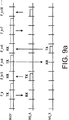
上記の説明は、単一のスロットパケットに関するものである。そして、それぞれのパケットは、ある監視時間の許容誤差で、あるタイムスロットの間に送信されるものであることがいえる。コネクションのスループットを増加させるために、例えば、ブルートゥースシステムで処理されるように、多重スロットパケットを使用することは有利である。多重スロットパケットは、コネクションのオーバヘッド、例えば、パケットヘッダとパケットペイロードへ監視時間との比率、を減少することによって、より高いスループットが得られる。このことは、図6Aと図6Bに対応する図9Aと図9Bに示される。図9Aと図9Bでは、それぞれ、端末MS_Aと端末MS_Bに無線機RAD1に接続するより高いスループットを得るために、多重スロットパケットを使用することが示される。図9Aと図9Bでは、端末が1つのスロットパケットを無線機に送信し、そして、無線機RAD1は、端末MS_Aへも3つのスロットパケットを送信し、端末MS_Bへ2つのスロットパケットを送信する。この構造は、図6Aと図6Bのように端末によって要求される3:1と2:1のダウン/アップリンク帯域幅比と矛盾しない。
【0040】
図9Aと図9Bでは、各多重スロットパケットはそれぞれ1つの搬送波周波数だけで送信されることを示しており、この搬送波周波数は、多重スロットパケットが開始されるスロットに基づくホップ周波数のシーケンスから決定される。例えば、MS_Aへの第1(図9Aにおける最左翼)のTXスロットは、搬送波周波数F_kを使用する。そして、MS_Aへの次のTXスロットは、搬送波周波数F_k+4を使用する。多重スロットパケットに対して同一の搬送波周波数を使用し、単一スロット周波数ホッピングシーケンスに従ってその搬送波周波数を決定することが有利である。なぜなら、それによって、送信機と受信機がパケット(再同期に関するプリアンブルを必要とするもの)の間で再調節を必要とせず、送信機と受信機が最後に使用された搬送波周波数を追跡し続ける必要がない、というように通信システムを簡単にできるからである。しかしながら、パケットのスロット長に関係なく、パケットによって指示された所定シーケンスに従ったパケットに搬送波周波数を割当てるような他の構造もまた可能であることを理解できよう。
【0041】
図9Aと図9Bを比較すれば、図9Bに示すスロット構造が望ましいことがわかる。図9Bでは、TX及びRXスロットがそれぞれ集められている。それは、多重スロットパケットの使用を長さ5スロットまで可能にするからである。ここで、図9Aにおける構造は、多重スロットパケットの長さを3スロットまでにしか許容することができない。より長くすることによって、動的にリモート端末のいろいろな帯域幅需要に適応する通信システムの融通性を最大にする。
【0042】
有効な多くの搬送波周波数がある場合、リモート端末にスロットを集めて割当てる方法がたくさんある。単一の基地局にとってのタスクは、ポピュラーなゲームであるテトリスのように、組み合わせパッキング問題の解決策を見つけることであることを理解できよう。N個のサービス(ユーザ)とK個の無線機がある場合、考えられる組み合わせはKN/KあるいはKN-1である。そして、通常、最高の効率(すなわち、ほとんど使用されていないスロットを最小にすること)を有する組み合わせが求められる。それにもかかわらず、全部の効率を最大にすることは、パッキング問題において、必ずしも唯一の制約条件や境界条件を必要としない。例えば、1人以上のユーザが所定の帯域幅を有することもまた要求されてもよい。
【0043】
セルラ―無線電話における動的または適応型のチャネル割当てのような多くの領域に生じるこの種のパッキング問題を解決する方法がいくつかある。1つの単純な方法として、すべての可能な組み合わせを調べて、徹底的な調査を実行することがある。組み合わせの数が大きい場合、「模擬アニーリング法(Simulated annealing)」のような他の方法がより魅力的になることがある。「模擬アニーリング法」は、例えば充足可能問題に対して広く適用される既知の技術である。すなわち、ウィリアム=M=スピアーズ(William M.Spears)の「クリックス、カラーリング及び充足可能性:第2のDIMACSインプリメンテーションチャレンジ(Cliques, Coloring, and Satisfiability: Second DIMACS Implementation Challenge)」における「充足可能問題に対する模擬アニーリング法(Simulated Annealing for Hard Satisfiability Problems)」や、デヴィッド=S=ジョンソン(David S.Johnson)とマイケル=A=トリック(Michael A.Trick)の離散数学と理論的コンピュータ科学におけるDIMACSシリーズ(DIMACS Series in Discrete Mathematics and Theoretical Computer Science)第26号、533〜588ページ、アメリカ数学協会(American Mathematical Society)、1996年が一例である。出願人の発明によれば、割当て方法は、各ユーザによって設定された基準値の割当てに基づくものである。以下の説明では、いくつかの割当て方法が記載され、評価される。
【0044】
第1の方法は、フレーム構造によるスロット割当てを制限しないリンクフォーマットを通信システムに使用させるものである。そのような通信システムの例が、ブルートゥースシステムである。これは、通信セッションに参加するトランシーバの1つがマスタユニットとなるもので、他の装置中のいかなる他のセッションからも独立し、完全に自由にセッションにスロットを割当てるものである。さらに、3つの無線機とそれぞれ6:1、5:1、4:1、3:1及び2:1のダウン/アップリンク帯域幅比を有する5つのリモートユーザA、B、C、D、Eを備える多重無線基地局がそのシステムに含まれる。
【0045】
第1の方法は、システムの効率、または全スループットを最大にするという目標を有している。この目標は、例えば、図10Aに示されるように、できるだけ頻繁に基地局内ですべての無線機を使用することによって達成される。第1の方法のフローチャートが、図11Aに示される。第1の方法における第1ステップ1100は、要求される帯域幅比を減少するためにリモートユニットと、利用可能な基地局無線機とを一対一に割当てるものである。この例においては、第1ステップ1100によって、最大帯域幅比(6:1)を要求するユニットAとして、例えば、無線機RAD1のような1番目の無線機を割当て、次に大きい帯域幅比(5:1)を要求するユニットBとして、例えば、無線機RAD2にような2番目の無線機を割当て、次に大きい残りの帯域幅比(4:1)を要求するユニットCとして、例えば、無線機RAD3のような最後に残っている利用可能な無線機に割当てるようになる。第1の方法における第1ステップ1100の後、基地局における無線機は、それぞれリモートユニットに割当てられている。
【0046】
第1の方法における次のステップ1102によって、ステップ1100で端末を割当てたときの逆順で割当てられる基地局無線機に、要求される帯域幅比を減少するために、残りのリモート端末が一つずつ割当てられる。この例では、ステップ1102によって、次に大きい残りの帯域幅比(3:1)を要求するユニットDとして、無線機RAD3が割当てられ、最後の残りの帯域幅比(2:1)を要求するユニットEとして無線機RAD2が割当てられる。
【0047】
一般に、全スループットを最大にするという目標のパッキング問題を解決するには、帯域幅比を減少する順に一種のジグザグ順、すなわち、RAD1、RAD2、…、RADN−1、RADN、RADN、RADN−1、…、RAD2、RAD1、RAD1、RAD2…の順で無線機に対してリモート端末を割当てる。したがって、例えばユニットF、G、Hが1:1の帯域幅比をそれぞれ有する場合、ユニットFは無線機RAD1に割当てられ、ユニットGは無線機RAD1割当てられ、ユニットHは無線機RAD2に割当てられるであろう。(等しいサービス要求を有する端末は交換可能であることに触れておく)。
【0048】
図10Aに関して、この例における各多重スロットTX(ダウンリンク)パケットは、対応するRX(アップリンク)パケットを有している。そして、図はこれらのパケットは、時間的にグループ化され、フレームの中に搭載されることを示す。例えば、無線機RAD2は、TXパケット2E、5BをそれぞれリモートユニットE、Bに送信する(数字2と5は、TXパケットのスロット長を示す)。そして、これらのユニットから1スロット長のRXパケットE、Bを受信する。図10Aに示されるように、無線機RAD1からRAD3にリモートユニットAからEを充当するための第1の方法は、9スロット分の有効なフレーム長をもたらす。これは、7つのTXスロットと2つのRXスロットの合計と、7:2の全帯域幅比である。ドットパターンによって表現された無線機RAD1上の2つのスロットは使用されていない。ユーザの帯域幅要求が同一のままで残っている限り、このような有効なフレームが連続して繰り返され、この割当ての効率は、(3×9−2)/(3×9)=25/27である。(スロットのすべてが使用される場合、効率は27/27または1となり、全体でのスループットが最大になるであろう。)これらの有効なフレームは、それらが割当て方法の再適用の引き金となるユーザの帯域幅要求の変化に従って変化するという意味で「動的」である。
【0049】
全体でのスループットを最大にするよりもむしろ、特定のリモートユニットに関するスループットを最大にするシステムを考える。第2の実施例では、無線機とリモートユニットの数を、上述した実施例におけるものとする。そして、リモートユニットによって要求される帯域幅比をその例と同じものとする。しかし、2:1の帯域幅比を有するユニットEに最大スループットを要求させる。リモートユニットとスロットの最適な割当てが図10Bに示される。そして、この割当ては、図11Bのフローチャートによって示されるような第2の割当て方法によって生成される。
【0050】
第2の方法における第1ステップ1110は、割当てられた無線機がそのリモートユニットに対して排他的に使用されている状態で無線機の1つに最大スループットを要求するリモートユニットを割当てる。この例では、排他的にユニットEに対して無線機RAD1を割当てて、使用させる。第2の方法における次のステップでは、残りの無線とリモートユニットに対する第1の方法のステップと同じである。第2の方法における第2ステップ1112では、要求される帯域幅比を減少するために、残っているリモートユニットを1つずつ残りの利用可能な基地局に割当てられる。そして、必要であるならば、第2の方法における第3ステップ1114において、要求される帯域幅比を減少させるために、残っているリモートユニットが1つずつ、ステップ1112でなされた順序の逆順で基地局無線機に割当てられる。
【0051】
第2の方法によってなされる割当てが、図10Bに示される。この図では、無線機RAD1上のユニットEと、無線機RAD2上のユニットA、Dと、無線機RAD3上のユニットB、Cとが示される。示された割当てが、ステップ1112において最初に無線機RAD2を選ぶことによって、示された結果が生じることが理解されるだろう。この割当ての全フレーム長は、10:5の全帯域幅比に伴って、10TX+5RX=15スロットである。無線機RAD2、RAD3のそれぞれには4つの未使用のスロットがあることに触れておく。したがって、全効率は(3×15−8)/(3×15)=37/45に減少する。しかし、ユーザEの個々のスループットが、図10Aにおける3/9から図10Bにおける1(最大)にまで増加する。
【0052】
リモートユニットが動的に要求される帯域幅比を変えることができるので、ここで第3の実施例を考える。この例は、上記例において3:1の帯域幅比を有するリモートユニットDが、その要求される帯域幅比を1:3に変えるものであり、少なくともリモートユニットDが少なくとも2つの基地局の間に位置するものである。これは、反対の帯域幅比(例えば、N:1と1:N)を有するリモートユニットが、別々の基地局における別々の無線機に割当てられるという第3の割当て方法によって、扱うことができる。第3の方法によって生成される割当てが、図10Cに示される。そして、第3の方法のフローチャートが図11Cに示される。これは、図13と図14に関連して、以下でより詳細に説明される「マクロ的なリソース割当て」の態様である。
【0053】
この第3の例では、無線機とリモートユニットの数を第1の例のようにさせる。また、リモートユニットによって要求される帯域幅比も上記例と同じにするが、無線機RAD1はある基地局に存在し、無線機RAD2とRAD3は別の基地局に存在し、リモートユニットDが1:3の帯域幅比を要求する点は上記例とは異なる。図11Cのフローチャートに示されるこの第3の方法の第1ステップ1120は、帯域幅比1:xを有する全リモートユニットを認識して、それらをそのようなユニットを扱う予定の基地局と無線機とに割当てることである。基地局無線機RAD1が帯域幅比1: xを有するリモートユニットに割当てられると仮定する。したがって、リモートユニットDは、無線機RAD2、RAD3の一つに対してよりもむしろRAD1に割当てられる。第3の方法における次のステップ1122、1124は、(帯域幅比x:1を有する)残りのリモートユニットを、上述した第1の方法(または、さらに第2の方法)に従って、そのような比率として選択される基地局無線機に割当てる。第1の方法を使用した結果が、図10Cに示される。そして、この割当ては、無線機RAD1の上の8つの未使用の(TX)スロットと、無線機RAD2の上の2つの未使用のスロットと、無線機RAD3の上の1つの未使用のスロットによる、12スロットの全フレーム長と(3×12−11)/(3×12)=25/36の全効率を有する。
【0054】
より多くのリモートユニットが1:xの帯域幅比を要求する場合、それらを無線機RAD1に割当てるか、またはそのようなリモートユニットのために予約された追加無線機に割当て、そしてこれらのユニットが、上述した第1または第2の方法のどちらかに従って予約された無線機の中で割当てられることを理解できよう。事実、第3の例は、2つの無線機がx:1の帯域幅比を有するリモートユニットのために予約されるという状況として見られ、そしてそれらのリモートユニットは予約された無線機の中で割当てられる。
【0055】
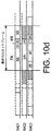
単一の基地局に対する異なる割当てが、図10Dに示される。この図は、同じ無線機RAD1上の帯域幅であって、その5:1の帯域幅比を用いるリモートユニットBと、1:3の帯域幅比を用いるリモートユニットDを示している。この割当ての全フレーム長は、図10Cに示されたような12スロットではなく10スロットである。そして、その全効率は25/30であって、基地局の全帯域幅比は6:4である。
【0056】
一般に、スロットの割当てに制限がなく(すなわち、フレーム制限がない)、個々のリモートユニットによるどんな特別なスループット要求もない場合、全効率は、全フレーム長(すなわち、無線機におけるTX及びRXスロットの総数)が最小にされるように、リモートユニットを割当てることによって最適化される。(図10Cと図10Dを比較する。)これはまた、図10Aと図10Bにおけるように自動的に利用可能な全無線機の使用をもたらすことになる。
【0057】
もしも、フレーム長を最小にする必要がないならば、あるユーザの帯域幅比を維持している間、そのユーザのTX及びRX周期を拡張することによって全効率を最適化することが可能であることに触れておく。これを示すために、5:1と3:1の帯域幅比を有する2つの無線機と2つのリモートユーザのシステムを仮定する。もしも、ユーザが単に異なる無線機に割当てられるならば、全効率は、(5:1の比のユーザによって決定される)6スロットのフレーム長に関して10/12である。3:1ユーザのフレームの連続組を見ることによって、そのユーザが6:2の帯域幅比を有すると考えることが許可される。5:1比ユーザと6:2比「ユーザ」とを、異なる無線機に割当てることによって、(6:2比「ユーザ」によって決定される)8スロットのフレーム長に関して、14/16の全効率がもたらされる。全体としての効率が増加し、ユーザが享受できる最大限度のスループットが変化してきた。
【0058】
最小フレーム長の境界条件を緩和することによって、可能な組み合わせ数が増加するので、パッキング問題の大きさが増加する。このような増加を制御するために、瞬時に発生するパケットトラヒック(メッセージ長とポーズ)のフレーム長または統計量を増加させることによって導入される遅延のしきい値のような、他の境界条件が課されてもよい。この種の組み合わせパッキング問題は上述したように有名であり、このアプリケーションで提案される特定の解決策は、限定的であるよりもむしろ例示的であると理解されなければならない。
【0059】
上述した例におけるように、動的に変動する全フレーム長を有するよりもむしろ、通信システムが、ほとんどの従来のセルラー無線システムにおける固定フレーム長を有すると仮定する。例えば、DECTシステムにおいては、各フレームは24スロットから成り、24スロットのそれぞれはTXまたはRXスロットのどちらかとして任意に選択される。固定長フレームを有するようなシステムには、リモートユニットを基地局無線機に割当てるオプション方法が2つある。
【0060】
第1の方法では、できるだけ多くのユニットが、できるだけ少ない無線機に割当てられる。第1の方法は、できるだけ多くの無線機が利用可能で残されるという利点を有するが、システムの全帯域幅比は実質的に固定されるようになる。図12Aは、3つの無線機を有する基地局と、上述した例と同じ帯域幅及び14スロットの固定されたフレーム長を有する5つのリモート端末A〜Eとから構成される通信システムにおいて第1の方法を適用することによってなされるスロット割当ての例である。図12Aの割当てにおいて、各14スロットフレームは、11個のTXスロットと3個のRXスロットを有している。そして、全5人のユーザA〜Eは、ちょうど2つの無線機に割当てられる。この方法を使用して、残りの無線機(その例におけるRAD3)は、現在固定された11:3の全帯域幅比が続いて提供されるので、追加ユーザへの割当てのために利用可能である。
【0061】
できるだけ多くの利用可能な無線機を残し、図12Aに示される割当てを導くためのパッキング方法は、要求されるTX及びRXスロットの総数にまず注目し、スロットにおけるフレーム長に従って除算し、切り上げ、その結果必要とされる無線機の最小数を決定することによって始められる。この例では、合計25スロット(20個のTXと5個のRX)が14スロットのフレームに配分されなければならない。そのため、少なくとも2つの無線機がそれらのスロットを提供するために必要である。次に、ユーザは要求される帯域幅比を減少させるために無線機に割当てられる。したがって、最も大きい比率を要求するユーザが、無線機の1つに割当てられる(図12AにおいてはユーザAはRAD1に割当てられている)。そして、次に大きい比率のユーザはその無線機に対して考慮される。この例では、ユニットBは14スロットフレーム評価基準以内で無線機RAD1に割当てられない。そのため、ユニットBは無線機RAD2に割当てられる、そして、ユニットCが無線機RAD1に対して考慮される。このプロセスを継続することによって、図12Aに示される割当てが導かれる。
【0062】
固定されたフレーム長のシステムに対する第2の割当て方法は、第1の方法における全帯域幅比を固定するのではなく、利用可能な基地局無線機のすべてを使用するものである。図12Bは、前の例のような通信システムにおける第2の方法を適用することによってなされるスロット割当ての例である。そこではすべての無線機RAD1、RAD2、RAD3が使用され、全帯域幅比は11:3に固定されるのではなく、TXスロットをRXスロットから切り離す破線がどのように移動することができるかを示す矢印によって指示されるように、最初のTXスロットが設置される位置に依存しながら、7:7から12:2の間で可変であることがわかる。したがって、もしも第4の無線機RAD4が基地局に提供されるならば、その無線機はそれらの帯域幅比に基づくリモートユニットを選択する際により融通性を有する。
【0063】
上述した説明は、基地局といくつかのリモートユーザに関するものであり、それぞれのユーザが帯域幅比要求を有している。出願人の発明は、このような通信システムに制限されるのではなく、それぞれが帯域幅比要求を有するサービスを運ぶピアツーピア接続を提供する通信システムに対して同様に有効である。このような通信システムでは、数人のユーザの代わりに(または、加えて)ひとつのリモートユーザがいてもよい。そして、そのユーザは、接続された異なるチャネルによってサポートされるいくつかのサービスを要求する。
【0064】
上述した説明において、スロット割当てとユーザ割当て(トラヒック計画とパッキング)のいくつかの方法が、単一基地局を有する通信システムのコンテクストで説明された。これは「ミクロ的なリソース割当て」と呼ばれるかもしれない。以下で、1以上の基地局を有する通信システムにおけるスロット割当てとユーザ割当てについて説明する。これは「マクロ的なリソース割当て」と呼ばれるかもしれない。もちろん、出願人のマクロ的及びミクロ的なリソース割当て手順が統合される場合、現実の通信システムのための最適な性能が得られることを理解できよう。
【0065】
マクロ的なリソース割当ては、「ホットスポット」、すなわち、高帯域幅が要求される領域を、1つのリモート端末が同時に多くの基地局からの信号を受信することができるような複数の基地局でカバーする通信システムにおいて特に有効である。このような通信システムが図13に示される。図では、それぞれの基地局BS1、BS2、BS3、BS4に対応するセルまたは領域1302−1、1302−2、1302−3、1302−4の共通部分によってカバーされる「ホットスポット」内に配置されるリモート端末MS_Aが示される。実際、リモート端末は、図13のBS1として示される最高の信号強度で受信される基地局信号に追跡(同期)する。通常、これはリモート端末に対して最小の送信損失を有する基地局に相当する。そして、その結果、おそらく最高のSN比を有するコネクションを提供する。
【0066】
それにもかかわらず、適応型チャネル割当て(例えば、上記で引用され具体化された米国特許第5,491,837を参照)を使用するシステム、または非調和周波数ホッピング(例えば、上記で引用されたブルートゥースシステムを参照)を使用するシステムにおいて、最も強い基地局にロックすることが必ずしも最適であるわけではない。実際に、リモート端末が接続を要求することは、しばしば最も強く受信される基地局ではなく、最高のTDD帯域幅を提供することができる基地局である。(これは、もちろんリモート端末によって要求されるサービスによる。)出願人のマクロ的なリソース割当て手順を以下で説明する。
【0067】
たいてい、リモート端末は、その端末の電力消費が低く、その端末が制御チャネルまたは最も強く受信された基地局の標識チャネルに追跡される不使用モード(パークあるいはスタンバイモードとも呼ばれる)であることが期待される。不使用モードにおいて、端末はたいてい「スリープ」であるが、基地局にそれ自体を再同期させて、何らかのページメッセージが待っているかをどうかを決定するための制御または標識チャネルに対して、一定の間隔で問い合わせるために「ウエイクアップ」する。もしも接続が望まれているならば(それは基地局によって開始されるか、またはリモート端末によって開始されるかのどちらかである)、リモート端末とその端末が追跡される基地局との間で初期接続が行われる。そして、初期メッセージが、要求されるタイプのサービスをネゴシエーションするためにこの接続上で交換される。特に、ダウンリンク/アップリンク帯域幅比がネゴシエーションされる。この情報は、基地局コントローラ(BSC)に対して基地局によって有効に送信される。BSCは、リモート端末の近隣の基地局によってサポートされるすべての接続を認識する。ここで引用されたようなシステムは、1999年3月19日にファイルされた出願人の米国特許09/272,212号の「非調和周波数ホッピングセルラーシステム(Uncoordinated Frequency Hopping Cellular System)」に記載されている。図13は、基地局BS1、BS2、BS3、BS4に接続されたBSCを示す図である。
【0068】
上述した説明の理由によって、(例えば、図5参照)複数の無線機を有する基地局は、そのダウンリンク及びアップリンク帯域幅を要求されたコネクションに割当てることに完全に自由であるというわけではない。図14のフローチャートによって示される出願人のマクロ的なリソース割当て方法の第1ステップ1402によれば、BSCは、完全に不使用であるか、既に要求されたコネクションとして同一ダウンリンク/アップリンク帯域幅比を要求する進行中にあるコネクションを有するかどちらかの基地局を捜す。図13は、4:1の帯域幅比を有する要求されたコネクションと、それぞれ5:1、3:1、1:3及び8:1の帯域幅比をサポートするう基地局BS1、BS2、BS3及びBS4を示す。特に、BSCは各基地局に対して信号接続を介してBSCに供給される情報に基づくTDD要求を妨害しないで、要求されるサービスをサポートすることができる基地局を捜す。もしも「新しい」端末MS_Aが5:1の帯域幅比を有するリンクを要求するならば、そのとき基地局BS1は、すでに5:1の帯域幅比を有するサービスをサポートするので、明らかにそのリンクをサポートする選択をする。
【0069】
もしも、そのような適合した基地局が見つけられないならば(ステップ1404)、要求されたサービスが再ネゴシエーションされるか(ステップ1406)、あるいは基地局の一つに対する既存の1つ以上の接続が「新しい」端末にサポートされることを許容するために再ネゴシエーションされる(ステップ1408)。例えば、もしも「新しい」端末MS_Aが4:1の帯域幅比を有するリンクを要求するならば、その特定の帯域幅比をサポートする範囲内の基地局はない。したがって、端末MS_Aは、基地局BS1か基地局BS4のどちらかに接続され、ステップ1406の結果、それぞれ5/6か5/9のどちらかに、最大スループットの減少を許す。一方、もしも、これらの基地局によって既に提供されたサービスがステップ1408の結果、スループットの減少を許容するならば、端末MS_Aは、基地局BS2か、基地局BS3かのどちらかに接続することができる。(基地局BS2の既存の接続が、そのスループットを4/5に減少させなければならないか、基地局BS3に既存の接続が、そのスループットを4/7に減少させなければならない。すなわち、端末MS_Aの新しい接続は、5/7以上のスループットを得られないであろう。)もしも、端末がスループットの低下を認めらるならば(ステップ1406)、その端末は、基地局内の無線機で利用可能であれば、自身を基地局BS1または基地局BS4に接続し続けるかどうかを決定することができる。しかし、これらの基地局における既存のリンクが影響するので、基地局BS2または基地局BS3への接続をし続けるためにはBSCの調停が必要である。
【0070】
出願人の発明は特定の実施例に関して上述のように説明される。そして、上述した記載内容以外の形式でその発明を具体化することが可能であるということは、当該技術分野における当業者にとって明らかである、上述された特定の実施例は単なる例示にすぎないものであり、どんな場合であっても限定的に考慮されるべきではない。発明の範囲は上述したクレームによって決定され、そして、クレームの範囲内にある全ての変形及び均等物は、クレームの範囲に含まれることが意図されている。
【図面の簡単な説明】
【図1】 TDDトランシーバのブロック図である。
【図2】 実質的に同一帯域幅を有するダウンリンクとアップリンクを備えるTDDチャネルを示す図である。
【図3】 ダウンリンクとアップリンクとの帯域幅間に3:1の比率を有するTDDチャネルを示す図である。
【図4】 ダウンリンクとアップリンクとの帯域幅間に1:2の比率を有するTDDチャネルを示す図である。
【図5】 TDD通信システムのための多重無線基地局のブロック図である。
【図6A】,
【図6B】 それぞれ3:1と2:1のリンク帯域幅比を有する2人のユーザをサポートする基地局の例を示す図である。
【図7A】,
【図7B】 それぞれ3:1、2:1及び4:1のリンク帯域幅比を有する3人のユーザをサポートする多重無線基地局の例を示す図である。
【図8A】,
【図8B】 それぞれ3:1、2:1及び1:1のリンク帯域幅比を有する3人のユーザをサポートする多重無線基地局の例を示す図である。
【図9A】,
【図9B】 多重スロットパケットを備えて3:1と2:1のリンク帯域幅比を有する2人のユーザをサポートする基地局の例を示す図である。
【図10A】,
【図10B】 全体の効率を最適化するスロット割当て方法の例を示す図である。
【図10C】,
【図10D】 反対の帯域幅比をサポートするスロット割当て方法の例を示す図である。
【図11A】,
【図11B】,
【図11C】 出願人の発明に従ったスロット割当て方法のフローチャートである。
【図12A】,
【図12B】 14個のスロットのフレーム長に対するスロット割当て方法の例を示す図である。
【図13】 出願人の発明に従ったマクロ的なリソース割当て方法を使用する通信システムを示す図である。
【図14】 出願人の発明に従ったマクロ的なリソース割当ての方法のフローチャートである。[0001]
background
The present invention relates to wireless communication, and more particularly to a cellular radiotelephone system using time division duplex communication.
[0002]
Mobile and cordless wireless telephone applications are increasingly widespread. In addition, cellular radiotelephone systems are well known and have developed to a high standard. A cellular system generally consists of a backbone network of multiple radio base stations located at strategic locations. Each base station covers a respective geographical area called a cell. Since adjacent cells partially overlap, a portable terminal such as a mobile phone can move from one cell to another without interruption of communication with the backbone network. When a mobile terminal moves between communication sessions, a connection is handed off from one radio base station to another according to a process according to the location of the mobile terminal relative to the base station.
[0003]
Around the world, cellular systems continue to be deployed to provide nationwide public telephones. The latest examples of wide area mobile phone systems include GSM (Global System for Mobile Communications), D-AMPS (Digital Advanced Mobile Phone System), CDMA (IS-95) system, and PDC (Personal Digital Cellular) system. These systems are operated by operators who provide a variety of public services, typically using portions of the radio spectrum licensed by national supervisory authorities.
[0004]
In addition to these licensed spectrum cellular communication systems, new types of cellular systems are entering the market, and currently include indoor environments (eg, companies, homes, exhibition halls, etc.) and local areas (eg, , School campuses, company parking lots, etc.). These new systems use an unlicensed portion of the radio spectrum of the industrial, scientific and medical (ISM) bands that are privately owned and generally widely used at 900 MHz, 2400 MHz and 5700 MHz. Examples of such mobile communication systems that use unlicensed spectrum in the local area are DECT (Digital European Cordless Telephone) systems, PHS (Personal Handyphone System), and WLANs (wireless local area computer networks).
[0005]
Skillful resource allocation in cellular systems is extremely important. In order to connect a mobile terminal or cordless terminal to a backbone network, an access point to the network (eg, a wireless base station) and a wireless channel for connecting the terminal to the access point must be available . Both access points and radio channels can be considered system resources that can be assigned. When a connection is established, the access point and / or terminal must select a radio channel, but there are insufficient radio resources. The concept of a cellular system is a method that supports many terminals in a limited radio spectrum, and this spectrum is distributed to multiple channels that can be used simultaneously in different connections, and the mutual interference with the intended received signal. The smaller the is, the farther the geographical distance between users joining different connections is.
[0006]
In most cellular systems, the access point closest to the remote terminal seeking connection is assigned to that terminal. This is because the access point typically supplies the lowest propagation loss to the terminal. The remote terminal periodically scans the spectrum for control or beacon signals broadcast by the access point of a given radio channel. Each terminal then tracks or synchronizes itself with the strongest control or beacon channel it receives.
[0007]
In some mobile systems, the terminal does not track to the strongest access point by default, for example whether the base station has an available radio channel and / or interference of all available radio channels. Choose an access point based on other criteria, such as whether or not is sufficiently low. In fact, it is not the channel with the highest peak carrier power, but the channel with the highest carrier-to-interference (C / I) ratio. An exemplary communication system based on base station and channel selection based on C / I ratio is “Method and System for Channel Allocation Using Power Control and Mobile-Assisted. U.S. Pat. No. 5,491,837 issued to Haartsen as "Handover Measurements", which is incorporated herein by reference.
[0008]
In general, according to the particular access technology used by the communication system, a “channel” is a carrier frequency, a time slot, a code or a hybrid thereof. In a frequency division multiple access (FDMA) system, the radio channel is a radio frequency (RF) carrier signal for transmission that is normally assigned between communication sessions and an RF carrier signal for reception. (Normally, transmission and reception can be simultaneously performed by separating a transmission carrier and a reception carrier selected from each of the dedicated bands, which are called frequency division duplex (FDD).) Advanced mobile telephone system (AMPS) and Nordic A mobile telephone (NMT) system is an example of a simple FDMA system that uses carrier frequency modulation. In a time division multiple access (TDMA) system such as GSM, each carrier signal is time shared by up to eight users. That is, each carrier signal transmits a continuous frame of 8 time slots each, and one or more time slots of each frame are assigned to the session. In a direct-sequence code division multiple access (CDMA) system, the transmitted information bit stream is effectively superimposed on a faster bit stream composed of successive repetitions of a unique code sequence. . The superimposed bit stream is scrambled by multiplication with another bit stream, usually pseudo-noise, as a result of being transmitted as a modulation of the RF carrier signal.
[0009]
First generation cellular systems, such as AMPS and NMT systems, are analog, where the transmitted analog (time-sequential) information signal modulates the frequency of the carrier signal. Although the transmission of low-speed digital data is possible by using an analog modem, the main role of the analog system is voice service. In second-generation systems such as GSM and D-AMPS, the information signal to be transmitted is digital (binary bit), and the information is compressed, error-correction coded, packed into packets, and transmitted in bursts or packets. Make it possible. Thus, the carrier signal need not be constantly used for one connection. Alternatively, the carrier can be divided into multiple slots. Different slots can be assigned to different users as in TDMA. In current second generation TDMA systems, like CDMA systems, the spectrum is further divided into several bands of carrier frequencies, so such systems also have FDMA elements. This results in a hybrid FDMA / TDMA system when each carrier is divided into time slots. And if each user is separated by their own code, this results in a hybrid FDMA / CDMA system. Also, the hybrid FDMA / TDMA / CDMA system has been described.
[0010]
Another advantage of the time slot system is that downlink (base station to remote terminal) and uplink (remote terminal to base station) transmissions do not occur simultaneously and FDD is not required. is there. Instead, downlink and uplink transmissions occur in different time slots on the same carrier called time division duplex (TDD). Full-duplex operation is obtained by alternating transmission and reception. Communication systems such as cellular systems used for wide area services still use FDD. Here, since the FDD helps to prevent interference between access points, it is preferable that the access point is installed at a high position. In indoor communication systems and other high-speed data systems, TDD is preferred because its spectrum is not divided into dedicated downlink and uplink bands. This means that the transmission and reception processes occur continuously on the same hardware, avoiding expensive duplexers that need to be well separated between transmitter and receiver hardware, so Costs can be reduced. Furthermore, downlink and uplink channels can be selected from the entire spectrum band.
[0011]
In conventional TDD systems, such as DECT systems, the downlink and uplink channels use the same carrier frequency. In more advanced TDD systems, such as the “Bluetooth” system, the following frequency hopping concept is used. That is, downlink transmission and uplink transmission occur in different time slots, but regardless of whether the slot is a downlink slot or an uplink slot, the carrier frequency for each slot is different and specified Can be any carrier in the radio band. Information about the Bluetooth system is available at http://bluetooth.ericsson.se/bluetooth/default.asp.
[0012]
In symmetric services such as voice communication, the bandwidth required on the downlink and uplink is substantially the same (both spend more or less equal talk time). As a result, it makes sense to divide the radio band into a downlink part and an uplink part with substantially the same size. However, data services are generally asymmetric. That is, the bandwidth required on the downlink and uplink is not substantially equal (some parts spend more download time than others). As a result, it is not very attractive that the downlink and the uplink are of the same size. Some services, such as Internet services, require much more downlink bandwidth or capacity than the uplink bandwidth, and vice versa. In the former case, it is desirable that the downlink bandwidth is larger.
[0013]
In an FDD system, the downlink and uplink bandwidth are usually fixed and cannot be changed. That is, there is a strict separation between downlink and uplink frequencies. In the TDD system, the downlink and uplink channels are not strictly separated, so that the downlink and uplink channels can be allocated more flexibly. In fact, the entire bandwidth can be temporarily allocated to provide downlink or uplink services exclusively. As described above, in the TDD system, a channel is divided into continuous time slots, and one or more packets or bursts are transmitted between the slots. For symmetric links, the slot assignment between downlink and uplink transmissions is substantially the same. Also, for asymmetric links, for example, the downlink is allocated more slots than the uplink. This assignment is performed dynamically. That is, as traffic demand changes, the bandwidth allocation between the downlink and uplink can be changed by changing the slot allocation.
[0014]
Nevertheless, the flexibility of TDD slot assignment is also limited. A TDD radio transceiver can either transmit or receive, but not simultaneously. For base stations with a single transceiver, this is not a drawback, but rather an advantage since expensive duplexers can be avoided. However, this causes some problems if the base station has to have additional transceivers to increase capacity. If transmission and reception occur in different bands, duplexers are not a problem, but the transmitter and receiver are the same as when the transmission and reception frequencies are the same band and multiple radios must be combined into a single base station. When the machine is physically close, simultaneous transmission and reception is not possible. This is because when the transmitter transmits, the front end of the receiver with a relatively high level signal in the same position is saturated. The level difference between the signal received from the transmitter at the same position and the signal received from the remote terminal is 70 dB or more. The level difference is so great that the base station receiver is not likely to be able to successfully filter the required signal from the remote terminal from the interfering signal from the co-located transmitter.
[0015]
The only known method so far where many TDD transceivers are integrated into the same base station is to synchronize their downlink and uplink transmissions so that all transceivers transmit or all transceivers receive simultaneously. It is to let you. This prevents the receiver from being hidden by one or more transmitters. In addition, there is almost no problem for a system that provides a symmetrical service. Synchronized downlink and uplink transmissions simply mean that the slots are assigned so that the slots are aligned between downlink slots on different radios and are aligned between uplink slots on different radios. It means you have to. However, asymmetric services are severely limited by the downlink / uplink synchronization requirement that asymmetric (ie, imbalance between downlink and uplink bandwidth) is required to be the same at the radio.
[0016]
International publication number WO 99/26430 Describes an adaptive time division duplex method and apparatus for duplex transmission of communication links in a wireless communication system. Communication link bandwidth requests are constantly monitored using predetermined bandwidth request parameters. The uplink and downlink bandwidths then adapt to dynamically contact the communication channel requirements. However, WO 99/26430 However, the allocation of bandwidth requests among multiple radio transceivers in a base station is not explicitly stated.
Accordingly, the object of the present invention is to solve these problems in the above-mentioned TDD communication system and to support asymmetric services in TDD systems with multiple radio units to provide sensible resource allocation and smart control of asymmetric traffic. A method and apparatus for using the
[0017]
wrap up
In a TDD communication system according to Applicant's invention, base station selection and channel selection are based on required service asymmetry, received signal strength and channel availability. In a multiple radio base station, downlink / uplink slots are preferably allocated so that all radio base stations can transmit and receive simultaneously. Multiple slots are selectively packed to achieve optimal throughput for all users as individual users or groups. In a system having a plurality of base stations covering the same area, it is preferable that the base stations are selected so that terminals having substantially the same downlink / uplink asymmetry are connected to the same base station. .
[0018]
In one aspect, the present invention provides a communication system for establishing a communication link between a multiple radio base station and a number of remote terminals, wherein each remote terminal requests a specific bandwidth ratio, and (a) each remote terminal The remote terminals are sequentially assigned to the available base station radios in descending order of the required bandwidth ratio, and (b) after the available base station radio is assigned the first remote terminal. A method for assigning slots to communication links including a step of assigning remaining remote terminals to base station radios in reverse order constructed in step (a) in order from the highest bandwidth ratio required by each remote terminal I will provide a.
[0019]
In another aspect, the present invention provides a communication system for establishing a communication link between multiple radio base stations and a number of remote terminals, wherein each remote terminal requests a specific bandwidth ratio, and (a) Determine the minimum number of base station radios required to support the transmission request, and (b) in order from the highest bandwidth ratio required by each remote terminal, the minimum determined in step (a) Continuously assigning remote terminals to available base station radios selected from a number of base station radios, (c) after each available base station radio is assigned the first remote terminal, In order from the highest bandwidth ratio required by the remote terminal, the slot is assigned to the communication link including the step of allocating the remaining remote terminals to the reverse-order base station radio constructed in step (b). To provide a method of assigning.
[0020]
In yet another aspect, the present invention provides a communication system. The system includes a base station with a plurality of radio transceivers, a number of remote terminals, and a radio transceiver among a plurality of remote terminals located within range of the base station to establish a communication link connecting to the remote terminals. And a controller for allocating slots to the base station radio according to a packing scheme that synchronizes transmission and reception timings of multiple base station radio communication links.
[0021]
Detailed description
The TDD communication system according to Applicant's invention is very flexible when providing data services. The reason is that the bandwidth can be dynamically allocated or reassigned among the system users by assigning or reassigning the time slot on the carrier signal to the user according to the user's needs.
[0022]
An example of a hardware structure related to the
[0023]
As seen in the simplified display of FIG. 1, information (TX information) transmitted by
[0024]
As mentioned above, wireless systems that use digital modulation typically have a carrier signal that is divided into successive time slots. FIG. 2 is a diagram showing a slot structure of a TDD system having base stations BS and mobile stations MS that alternately transmit and receive. A packet or burst containing a sequence of information bits is sent in each time slot. Successive time slots are identified by the continuous code k and the carrier frequency used in the slots identified by, for example, F_k, G_k, etc. Here, F and G indicate different hop sequences. Some communication systems employ packets carrying 30-300 bytes of information. In principle, in a TDD system, each slot can determine whether that slot is used for transmission or reception. Furthermore, the carrier frequency used for each slot is the total effective frequency given to the spectrum occupied by the communication system. In many conventional TDD systems, the carrier frequency F_k used in one slot is the same as the carrier frequency F_k + 1 used in the next slot. That is, the same carrier frequency is used for all transmissions and receptions between the BS and the MS. In more advanced systems, the carrier frequency F_k used in one slot is not the same as the carrier frequency F_k + 1 used in the next slot. That is, a different carrier frequency is selected for each slot. In these more sophisticated systems, the transmitter and receiver radios hop synchronously according to a mutually perceived hopping sequence, which is usually pseudo-random.
[0025]
As shown in FIG. 2, when radios transmit and receive each other, the bandwidth in the uplink is the same as the bandwidth in the downlink. In the downlink, the same type of packet (eg, the same error correction coding, etc.) used in both links is provided. This gives a symmetric or balanced link. According to Applicant's invention, it is possible to change the balance and increase one bandwidth in the TDD system at the expense of the other. This is illustrated in FIG. In FIG. 3, a slot structure is shown in which the bandwidth of the uplink (from BS to MS) is 3 times the uplink bandwidth, i.e., there is a 3: 1 ratio between the link bandwidths. In essence, three times as many slots allocated for the uplink (eg, slots using carrier frequency F_k + 3) use the downlink (eg, carrier frequencies F_k, F_k + 1, F_k + 2). Slot).
[0026]
Of course, it is desirable that the downlink and uplink bandwidths are determined by the respective service requirements of the downlink and uplink. In voice services, both speakers should have the same bandwidth, and each speaker expects to speak half time, so usually a symmetric link with a 1: 1 bandwidth ratio or A balanced link is required. However, data applications inherently tend to unbalance links. For example, services for client / server applications usually require more bandwidth from the server to the client. This is because the information flow in the other direction is usually just low-speed control information. In the TDD communication system, an unbalanced service can be constructed at high speed. And because the same service may require different bandwidth allocations at different moments, bandwidth allocation is performed dynamically. For example, the downlink and uplink have a bandwidth ratio of 3: 1 at one instant as shown in FIG. 3, but at a ratio of 1: 2 at another instant as shown in FIG. It may be. Dynamic bandwidth allocation is important in TDD systems according to Applicants' invention. A TDD system allocates (dynamically) bandwidth so that the same number of slots is allocated to the downlink and uplink (eg, a 1: 1 bandwidth ratio as shown in FIG. 2). You can understand that you can also support symmetrical services.
[0027]
Such effective bandwidth allocation is realized simultaneously for a plurality of different connections by the multiple
[0028]
[0029]
Using TDMA, a single radio base station can support several users by assigning different time slots to different users. An empirical slot structure for this type of operation for a communication system including a base station BS and two remote terminals MS_A, MS_B is shown in FIGS. 6A and 6B. The system assigns different slots to mobile stations MS_A and MS_B, as indicated by vertical arrows of different lengths. And in both figures, the downlink / uplink bandwidth ratio is 3: 1 for MS_A and 2: 1 for MS_B. It will be appreciated that, in general, any particular uplink slot need not appear immediately (or immediately before) the corresponding downlink slot. FIG. 6A shows a case where the BS and MS_A exchange bidirectional slot sets. BS and MS_B indicate a case where a pair of bidirectional slots and the like are exchanged. For example, the link radio is switched between 3: 1 and 2: 1. In FIG. 6B, both downlinks are generated in succession, and both uplinks are generated in succession, but the number of consecutive downlink slots is the uplink that is consecutive immediately after the downlink. If the bandwidth ratio is evaluated by dividing by the number of slots, it can be considered as a kind of 5: 2 combined bandwidth ratio. It can be appreciated that FIGS. 6A and 6B show that both MS_A and MS_B show the same throughput performance.
[0030]
Although the base station can use a single radio as shown in FIG. 1 for multiple users, as described with respect to FIGS. 6A and 6B, the bandwidth of a single radio is In particular, when a high-speed data service is required, it is used up quickly. Bandwidth can be increased by adding other radios to the same base station and assigning different users to one of the different radios. This can be seen from FIGS. 7A and 7B. That is, FIGS. 7A and 7B show a slot structure for the expansion of FIGS. 6A and 6B. Here, the base station includes two radio devices RAD1 and RAD2, and a third remote terminal MS_C is added. In FIG. 7A, the radio RAD1 is completely occupied by a link having the same structure as in FIG. 6A. In FIG. 7B, the radio device RAD1 is completely occupied by a link having the same structure as that in FIG. 6B. Therefore, the second radio device RAD2 is necessary for the third terminal MS_C. According to the applicant's invention, the service request of the remote terminal is included in the radio.
[0031]
In order to understand some constraints on this kind of packing problem, for the example of FIG. 6A where the terminals MS_A and MS_C are being serviced and the terminal MS_C requires a service with a bandwidth ratio of 4: 1. Consider. Here, traffic on radios RAD1 and RAD2 must be constructed so that both radios can transmit and receive at the same time, which is not the situation in FIG. 7A where the time slots of RAD1 and RAD2 are aligned. Conceivable. Since the frequency hopping sequences used by the two radios are not necessarily the same, that is, F_k ≠ G_k, it is possible to prevent at least the radios from interfering with each other. Because they do not transmit the same carrier at the same time.
[0032]
Nevertheless, RAD1 and RAD2 interfere with each other in the slot indicated by the dashed arrow that one transmits and the other receives. For example, the leftmost broken line in FIG. 7A is shown in the slot when radio RAD1 receives and radio RAD2 transmits. Between these slots, not only RAD1 but also RAD2 cannot receive data from any of MS_A, MS_B and MS_C. Because the signal received by the base station from the remote terminal is in the nanowatt to picowatt range, the power level of the signal transmitted by the base station is usually in the milliwatt range for short range systems. Yes, as long range systems may be as high as several kilowatts. Thus, if the base station transmitter transmits at the same time as the remote terminal, the base station receiver will receive a digit more than the signal coming from the mobile terminal even when the base station radio using the same spectrum band provided F_k ≠ G_k. Signals of strength that are several steps higher can cause a base station receiver to saturate due to signal leakage from nearby base station transmitters.
[0033]
To prevent the base station receiver from blocking the remote terminal signal, the transmission and reception of RAD1 and RAD2 must be synchronized. In order to be able to provide the necessary services and to prevent this interference situation from occurring, the timing of RAD2 must not be changed. Applicant's invention solves this problem.
[0034]
In the first embodiment, since transmission and reception are selectively planned so that all remote terminals (three terminals in the previous example) are serviced, the above-mentioned problems are not encountered. For clarity, consider the service and slot structure shown in FIG. 6B. Then, RAD1 is operated as shown in FIG. 7B. As can be seen from FIG. 7B, the 4: 1 bandwidth ratio service of MS_C is provided by RAD2 without interfering with RAD1. Here, RAD1 is supplied such that two extra unused slots are added to the slot structure of RAD2. As described above with respect to FIG. 6B, the slot structure of RAD1 has an overall bandwidth ratio of 5: 2 and an extra slot for RAD2. The extra slots are intended to fill or embed the RAD2 slot structure from the 4: 1 bandwidth ratio required by MS_C to a 5: 2 ratio. Therefore, transmission / reception of different radios in the multiple radio base station is planned so that the total bandwidth ratio of different radios is the same and transmission / reception by different radios occurs in the same slot.
[0035]
Note that the price paid for this scheduling is reduced throughput to MS_C. That is, the link between RAD2 and MS_C is the currently free part. In the example shown in FIG. 7B, only 5/7 of the maximum throughput is used to provide the 4: 1 bandwidth ratio service required by MS_C. (If all slots are occupied, maximum link throughput is obtained.) When a radio plans transmission and reception according to the present invention, the throughput to a user like MS_C should be less than the link maximum. Therefore, when assigning a radio to a user, it is desirable to take into account the user's minimum acceptable throughput according to the bandwidth ratio required by the user.
[0036]
As another example for the operation of Applicants' invention, assume that user MS_C requires a balanced link, ie, a 1: 1 bandwidth ratio. Starting with a slot structure as shown in FIG. 6A, MS_C corresponds as shown by FIG. 8A. Also, starting from the slot structure of FIG. 6B, MS_C corresponds as shown in FIG. 8B. In FIG. 8A and FIG. 8B, by assigning MS_C to RAD2 and planning the transmission and reception of RAD2 to coincide with the transmission and reception of RAD1, respectively, three extra empty slots in the RAD2 structure are obtained. Only 4/7 of the maximum link throughput is used for user MS_C.
[0037]
From FIG. 8A and FIG. 8B, it can be appreciated that the specific processing of the extra slots is not important as it is provided to match the transceiver transmission and reception. Therefore, for example, in FIG. 8A, TX information transmitted in a slot corresponding to the carrier
[0038]
Although the slot structures shown in FIGS. 8A and 8B lead to the same results in terms of throughput and bandwidth for users MS_A and MS_B, they bundle as many transmit and receive slots as possible, as shown in FIGS. 6B, 7B, and 8B. Or gathering is currently considered desirable. Aggregating slots provides more flexibility in allocating to new users and allocating the required bandwidth ratio between radios. In particular, this is the case when multi-slot packets are used as described in more detail below. The
[0039]
The above description relates to a single slot packet. Each packet is transmitted during a certain time slot with a certain monitoring time tolerance. In order to increase the throughput of the connection, it is advantageous to use multi-slot packets, for example as processed in a Bluetooth system. Multi-slot packets provide higher throughput by reducing connection overhead, eg, the ratio of packet header to packet payload to monitoring time. This is illustrated in FIGS. 9A and 9B corresponding to FIGS. 6A and 6B. In FIG. 9A and FIG. 9B, it is shown that multi-slot packets are used to obtain higher throughput connecting to the radio RAD1 to the terminals MS_A and MS_B, respectively. 9A and 9B, the terminal transmits one slot packet to the radio, and the radio RAD1 transmits three slot packets to the terminal MS_A and transmits two slot packets to the terminal MS_B. This structure is consistent with the 3: 1 and 2: 1 downlink / uplink bandwidth ratio required by the terminal as in FIGS. 6A and 6B.
[0040]
9A and 9B show that each multi-slot packet is transmitted on only one carrier frequency, which is determined from a sequence of hop frequencies based on the slot from which the multi-slot packet begins. The For example, the first (leftmost in FIG. 9A) TX slot to MS_A uses the carrier frequency F_k. The next TX slot to MS_A then uses the carrier
[0041]
9A and 9B, it can be seen that the slot structure shown in FIG. 9B is desirable. In FIG. 9B, TX and RX slots are collected respectively. This is because the use of multi-slot packets up to 5 slots in length is possible. Here, the structure in FIG. 9A can only allow the length of a multi-slot packet up to 3 slots. By making it longer, it maximizes the flexibility of the communication system to dynamically adapt to the various bandwidth demands of the remote terminal.
[0042]
If there are many valid carrier frequencies, there are many ways to collect and assign slots to remote terminals. It can be seen that the task for a single base station is to find a solution to the combinatorial packing problem, like Tetris, a popular game. If there are N services (users) and K radios, the possible combinations are KN/ K or KN-1It is. Then, a combination is usually sought that has the highest efficiency (ie minimizing slots that are rarely used). Nevertheless, maximizing overall efficiency does not necessarily require a unique constraint or boundary condition in the packing problem. For example, it may also be required that one or more users have a predetermined bandwidth.
[0043]
There are several ways to solve this type of packing problem that occurs in many areas, such as dynamic or adaptive channel assignment in cellular radiotelephones. One simple method is to examine all possible combinations and perform a thorough investigation. When the number of combinations is large, other methods such as “simulated annealing” may become more attractive. The “simulated annealing method” is a known technique widely applied to, for example, satisfiable problems. That is, “Satisfaction” in William M. Spears' “Cricks, Coloring, and Satisfiability: Second DIMACS Implementation Challenge”. Simulated Annealing for Hard Satisfiability Problems ”, DIMACS in Discrete Mathematics and Theoretical Computer Science by David S. Johnson and Michael A. Trick The series (DIMACS Series in Discrete Mathematics and Theoretical Computer Science) No. 26, 533-588, American Mathematical Society, 1996 is an example. According to the applicant's invention, the allocation method is based on the allocation of reference values set by each user. In the following description, several allocation methods are described and evaluated.
[0044]
The first method is to allow the communication system to use a link format that does not restrict slot allocation by the frame structure. An example of such a communication system is the Bluetooth system. This is where one of the transceivers participating in the communication session becomes the master unit and is independent of any other session in other devices and assigns slots to the session completely freely. In addition, three radios and five remote users A, B, C, D, E with 6: 1, 5: 1, 4: 1, 3: 1 and 2: 1 downlink / uplink bandwidth ratios, respectively. A multiple radio base station comprising is included in the system.
[0045]
The first method has the goal of maximizing system efficiency, or overall throughput. This goal is achieved, for example, by using all radios in the base station as often as possible, as shown in FIG. 10A. A flowchart of the first method is shown in FIG. 11A. The
[0046]
The
[0047]
In general, to solve the target packing problem of maximizing the total throughput, a kind of zigzag order, ie, RAD1, RAD2,..., RADN-1, RADN, RADN, RADN-1, in order of decreasing bandwidth ratio. ,..., RAD2, RAD1, RAD1, RAD2,... Thus, for example, if units F, G, and H each have a 1: 1 bandwidth ratio, unit F is assigned to radio RAD1, unit G is assigned to radio RAD1, and unit H is assigned to radio RAD2. Will. (Note that terminals with equal service requirements are interchangeable).
[0048]
With reference to FIG. 10A, each multi-slot TX (downlink) packet in this example has a corresponding RX (uplink) packet. The figure shows that these packets are grouped in time and loaded into a frame. For example, the radio device RAD2 transmits
[0049]
Consider a system that maximizes throughput for a particular remote unit, rather than maximizing overall throughput. In the second embodiment, the number of wireless devices and remote units is assumed to be in the above-described embodiment. The bandwidth ratio required by the remote unit is the same as that example. However, it requires unit E to have a 2: 1 bandwidth ratio for maximum throughput. The optimal allocation of remote units and slots is shown in FIG. 10B. This assignment is then generated by a second assignment method as shown by the flowchart of FIG. 11B.
[0050]
A
[0051]
The assignment made by the second method is shown in FIG. 10B. In this figure, unit E on radio RAD1, units A and D on radio RAD2, and units B and C on radio RAD3 are shown. It will be appreciated that the indicated assignment produces the indicated result by first selecting radio RAD2 in
[0052]
Since the remote unit can dynamically change the required bandwidth ratio, consider the third embodiment. In this example, the remote unit D having a bandwidth ratio of 3: 1 in the above example changes its required bandwidth ratio to 1: 3, and at least the remote unit D is between at least two base stations. It is located in. This can be handled by a third allocation method in which remote units with opposite bandwidth ratios (eg, N: 1 and 1: N) are allocated to different radios at different base stations. The assignment generated by the third method is shown in FIG. 10C. A flowchart of the third method is shown in FIG. 11C. This is a “macro resource allocation” aspect described in more detail below with respect to FIGS. 13 and 14.
[0053]
In the third example, the number of radio units and remote units is set as in the first example. Also, the bandwidth ratio required by the remote unit is the same as in the above example, but the radio RAD1 exists in one base station, the radios RAD2 and RAD3 exist in another base station, and the remote unit D is 1 : 3 is different from the above example in that the bandwidth ratio is required. The
[0054]
If more remote units require a bandwidth ratio of 1: x, assign them to radio RAD1 or assign to additional radios reserved for such remote units, and these units It will be appreciated that the allocation is in the reserved radio according to either the first or second method described above. In fact, the third example can be seen as a situation where two radios are reserved for remote units with x: 1 bandwidth ratio, and those remote units are among the reserved radios. Assigned.
[0055]
Different assignments for a single base station are shown in FIG. 10D. This figure shows the remote unit B using the bandwidth ratio of 1: 3 and the remote unit D using the bandwidth ratio of 1: 3, which are bandwidths on the same radio device RAD1. The total frame length of this assignment is 10 slots instead of 12 slots as shown in FIG. 10C. The total efficiency is 25/30, and the total bandwidth ratio of the base station is 6: 4.
[0056]
In general, if there is no limit on slot allocation (ie, no frame limit) and no special throughput requirements by individual remote units, the overall efficiency is the total frame length (ie, the TX and RX slots in the radio). Optimized by assigning remote units so that the total number) is minimized. (Compare FIGS. 10C and 10D.) This will also result in the use of all radios automatically available as in FIGS. 10A and 10B.
[0057]
If it is not necessary to minimize the frame length, it is possible to optimize the overall efficiency by extending the user's TX and RX periods while maintaining the bandwidth ratio of a user. Let me mention that. To illustrate this, assume a system of two radios and two remote users with bandwidth ratios of 5: 1 and 3: 1. If the users are simply assigned to different radios, the total efficiency is 10/12 for a 6 slot frame length (determined by a 5: 1 ratio user). By looking at a continuous set of frames for a 3: 1 user, it is allowed to think that the user has a bandwidth ratio of 6: 2. By assigning a 5: 1 ratio user and a 6: 2 ratio “user” to different radios, an overall efficiency of 14/16 for a frame length of 8 slots (determined by the 6: 2 ratio “user”) Is brought about. Overall efficiency has increased and the maximum throughput that users can enjoy has changed.
[0058]
Relaxing the minimum frame length boundary condition increases the number of possible combinations, thus increasing the size of the packing problem. To control this increase, other boundary conditions, such as delay thresholds introduced by increasing the frame length or statistics of instantaneous packet traffic (message length and pause), May be imposed. This type of combination packing problem is well known as described above, and the particular solution proposed in this application should be understood to be illustrative rather than limiting.
[0059]
Assume that the communication system has a fixed frame length in most conventional cellular radio systems, rather than having a dynamically varying total frame length, as in the example described above. For example, in a DECT system, each frame consists of 24 slots, each of which is arbitrarily selected as either a TX or RX slot. In systems with fixed-length frames, there are two optional methods for assigning remote units to base station radios.
[0060]
In the first method, as many units as possible are allocated to as few radios as possible. The first method has the advantage that as many radios as possible are left available, but the overall bandwidth ratio of the system becomes substantially fixed. FIG. 12A shows a first example in a communication system composed of a base station having three radios and five remote terminals A to E having the same bandwidth and the fixed frame length of 14 slots as the above-described example. It is an example of slot assignment made by applying the method. In the assignment of FIG. 12A, each 14-slot frame has 11 TX slots and 3 RX slots. All the five users A to E are assigned to exactly two radio devices. Using this method, the remaining radios (RAD3 in that example) are available for allocation to additional users as the current fixed 11: 3 total bandwidth ratio is subsequently provided. is there.
[0061]
The packing method for leaving as many available radios as possible and leading to the assignment shown in FIG. 12A first looks at the total number of required TX and RX slots, divides according to the frame length in the slots, rounds up, The result is started by determining the minimum number of radios required. In this example, a total of 25 slots (20 TX and 5 RX) must be allocated to the 14-slot frame. Therefore, at least two radios are required to provide those slots. The user is then assigned to the radio to reduce the required bandwidth ratio. Thus, the user requesting the highest ratio is assigned to one of the radios (user A is assigned to RAD1 in FIG. 12A). The next largest proportion of users is then considered for that radio. In this example, unit B is not assigned to radio RAD1 within the 14-slot frame evaluation criteria. Therefore, unit B is assigned to radio RAD2, and unit C is considered for radio RAD1. By continuing this process, the assignment shown in FIG. 12A is derived.
[0062]
The second allocation method for a fixed frame length system uses all of the available base station radios rather than fixing the total bandwidth ratio in the first method. FIG. 12B is an example of slot assignment made by applying the second method in the communication system as in the previous example. There, all radios RAD1, RAD2, RAD3 are used and the total bandwidth ratio is not fixed at 11: 3, but how the broken line separating the TX slot from the RX slot can move It can be seen that it is variable between 7: 7 and 12: 2, depending on the position where the first TX slot is installed, as indicated by the arrows shown. Thus, if a fourth radio RAD4 is provided to the base station, the radio has more flexibility in selecting remote units based on their bandwidth ratio.
[0063]
The above description relates to a base station and several remote users, each user having a bandwidth ratio requirement. Applicant's invention is not limited to such communication systems, but is equally effective for communication systems that provide peer-to-peer connections, each carrying services with bandwidth ratio requirements. In such a communication system, there may be one remote user instead of (or in addition to) several users. The user then requests several services supported by different connected channels.
[0064]
In the above description, several methods of slot assignment and user assignment (traffic planning and packing) have been described in the context of a communication system with a single base station. This may be called “micro resource allocation”. Hereinafter, slot assignment and user assignment in a communication system having one or more base stations will be described. This may be referred to as “macro resource allocation”. Of course, it will be appreciated that when the applicant's macro and micro resource allocation procedures are integrated, optimal performance for a real communication system is obtained.
[0065]
Macro resource allocation is a “hot spot”, ie, an area where high bandwidth is required, in multiple base stations where one remote terminal can receive signals from many base stations simultaneously. This is particularly effective in the communication system to be covered. Such a communication system is shown in FIG. In the figure, the cells or areas 1302-1, 1302-2, 1302-3, 1302-4 corresponding to the respective base stations BS1, BS2, BS3, BS4 are arranged in “hot spots” covered by common parts. Remote terminal MS_A is shown. In fact, the remote terminal tracks (synchronizes) with the base station signal received with the highest signal strength shown as BS1 in FIG. Usually this corresponds to a base station with minimal transmission loss for the remote terminal. And as a result, it probably provides the connection with the highest signal-to-noise ratio.
[0066]
Nonetheless, systems that use adaptive channel allocation (see, eg, US Pat. No. 5,491,837 cited and embodied above), or anharmonic frequency hopping (see, eg, the Bluetooth system cited above) In systems that use, locking to the strongest base station is not always optimal. Indeed, it is often the base station that can provide the highest TDD bandwidth, not the base station that is most strongly received, that the remote terminal requests for connection. (This of course depends on the service required by the remote terminal.) The applicant's macro resource allocation procedure is described below.
[0067]
Often, a remote terminal is expected to be in a non-use mode (also called park or standby mode) where the terminal's power consumption is low and the terminal is tracked to the control channel or the most strongly received base station beacon channel. Is done. In non-use mode, the terminal is usually “sleep”, but with a certain control or beacon channel to resynchronize itself to the base station to determine if any page message is waiting. “Wake up” to query at intervals. If a connection is desired (it is either initiated by the base station or initiated by the remote terminal), the initial connection between the remote terminal and the base station on which the terminal is tracked A connection is made. Initial messages are then exchanged over this connection to negotiate the required type of service. In particular, the downlink / uplink bandwidth ratio is negotiated. This information is effectively transmitted by the base station to the base station controller (BSC). The BSC recognizes all connections supported by base stations in the vicinity of the remote terminal. A system such as that cited here is described in Applicant's US patent application Ser. No. 09 / 272,212 filed Mar. 19, 1999, “Uncoordinated Frequency Hopping Cellular System”. . FIG. 13 is a diagram illustrating BSCs connected to base stations BS1, BS2, BS3, and BS4.
[0068]
For the reasons described above, a base station having multiple radios (eg, see FIG. 5) is not completely free to allocate its downlink and uplink bandwidth to the requested connection. . According to the
[0069]
If no such suitable base station is found (step 1404), the requested service is renegotiated (step 1406), or one or more existing connections to one of the base stations Re-negotiated to allow support for “new” terminals (step 1408). For example, if a “new” terminal MS_A requires a link with a 4: 1 bandwidth ratio, no base station is in range to support that particular bandwidth ratio. Accordingly, the terminal MS_A is connected to either the base station BS1 or the base station BS4, and as a result of
[0070]
Applicant's invention is described above with respect to specific embodiments. The fact that the invention can be embodied in forms other than those described above is obvious to those skilled in the art and the specific embodiments described above are merely examples. And should not be considered limited in any case. The scope of the invention is determined by the above claims, and all variations and equivalents that are within the scope of the claims are intended to be included within the scope of the claims.
[Brief description of the drawings]
FIG. 1 is a block diagram of a TDD transceiver.
FIG. 2 shows a TDD channel with downlink and uplink having substantially the same bandwidth.
FIG. 3 shows a TDD channel with a 3: 1 ratio between downlink and uplink bandwidths.
FIG. 4 shows a TDD channel having a ratio of 1: 2 between downlink and uplink bandwidths.
FIG. 5 is a block diagram of a multiple radio base station for a TDD communication system.
[FIG. 6A]
FIG. 6B is a diagram illustrating an example of a base station supporting two users having link bandwidth ratios of 3: 1 and 2: 1, respectively.
[FIG. 7A]
FIG. 7B is a diagram illustrating an example of a multiple radio base station supporting three users having link bandwidth ratios of 3: 1, 2: 1, and 4: 1, respectively.
[FIG. 8A]
FIG. 8B is a diagram illustrating an example of multiple radio base stations supporting three users with link bandwidth ratios of 3: 1, 2: 1, and 1: 1, respectively.
[FIG. 9A]
FIG. 9B shows an example of a base station supporting two users with multiple slot packets and having a 3: 1 and 2: 1 link bandwidth ratio.
[FIG. 10A]
FIG. 10B shows an example of a slot allocation method that optimizes overall efficiency.
[FIG. 10C]
FIG. 10D shows an example of a slot allocation method that supports opposite bandwidth ratios.
[FIG. 11A]
[FIG. 11B]
FIG. 11C is a flowchart of a slot allocation method according to Applicants' invention.
[FIG. 12A]
FIG. 12B is a diagram showing an example of a slot allocation method for a frame length of 14 slots.
FIG. 13 shows a communication system using a macro resource allocation method according to Applicant's invention.
FIG. 14 is a flowchart of a macro resource allocation method according to the applicant's invention;
Claims (5)
(a)前記複数のリモート端末の各々を、該複数のリモート端末の各々が要求する帯域幅比が減少する順で、利用可能な複数の基地局無線トランシーバの1つに順次割当てるステップと、
(b)前記ステップ(a)において前記複数のリモート端末の各々に対して割当てる基地局無線トランシーバが不足した場合、前記割当てが行われていない残りのリモート端末の各々を、該残りのリモート端末の各々が要求する帯域幅比が減少する順で、前記利用可能な複数の基地局無線トランシーバの1つに順次割当てるステップであって、該基地局無線トランシーバは、前記利用可能な複数の基地局無線トランシーバの中から前記ステップ(a)においてリモート端末に対して割当てられた順序とは逆順に順次選択される、順次割当てるステップとを含むことを特徴とする方法。A method of assigning slots in a TDD (Time Division Duplex) communication system for establishing a communication link between a multiple radio transceiver base station and a plurality of remote terminals, wherein the communication system includes a plurality of base stations at the same base station and at the same time. Configured to synchronize so that all of the station radio transceivers are either transmitting or receiving, each of the plurality of remote terminals requesting a transmit and receive slot of a predetermined bandwidth ratio A method comprising:
(A) sequentially assigning each of the plurality of remote terminals to one of a plurality of available base station radio transceivers in order of decreasing bandwidth ratio required by each of the plurality of remote terminals;
(B) If there is a shortage of base station radio transceivers assigned to each of the plurality of remote terminals in step (a), each of the remaining remote terminals not assigned is assigned to the remaining remote terminals. Sequentially assigning to one of the available base station radio transceivers, in order of decreasing bandwidth ratios required by the base station radio transceiver, the base station radio transceivers A step of sequentially assigning from the transceiver, wherein the steps are sequentially selected in a reverse order to the order assigned to the remote terminal in step (a).
最大スループットを要求する各リモート端末が、利用可能な基地局無線トランシーバに割当てられ、
割当てられた基地局無線トランシーバが利用可能な基地局無線トランシーバのプールから除かれることを特徴とする請求項1に記載の方法。At least one remote terminal requires maximum throughput,
Each remote terminal requesting maximum throughput is assigned to an available base station radio transceiver,
The method of claim 1, wherein the assigned base station radio transceiver is removed from the pool of available base station radio transceivers.
前記複数の無線トランシーバ(502−1、502−2、502−N)は、同一時刻において該複数の無線トランシーバ(502−1、502−2、502−N)のすべてが送信するかまたはすべてが受信するかの何れかであるように同期するように構成され、
前記複数のリモート端末の各々が、所定の帯域幅比の送信および受信スロットを要求し、該コントローラが、
(a)前記複数のリモート端末(504−1、504−2、504−N)の各々を、該複数のリモート端末(504−1、504−2、504−N)の各々が要求する帯域幅比が減少する順で、利用可能な複数の基地局無線トランシーバ(504−1、504−2、504−N)の1つに順次割当てる第1割当て手段と、
(b)前記第1割当て手段において前記複数のリモート端末の各々に対して割当てる基地局無線トランシーバが不足した場合、前記割当てが行われていない残りのリモート端末の各々を、該残りのリモート端末の各々が要求する帯域幅比が減少する順で、前記利用可能な複数の基地局無線トランシーバの1つに順次割当てる第2割当て手段であって、該基地局無線トランシーバは、前記利用可能な複数の基地局無線トランシーバの中から前記第1割当て手段においてリモート端末に対して割当てられた順序とは逆順に順次選択される、第2割当て手段と
を含むことを特徴とするTDD通信システム。Base station (500) comprising a plurality of base station radio transceivers (502-1, 502-2, 502-N) each establishing a communication link connecting with remote terminals (504-1, 504-2, 504-N) ), A plurality of remote terminals (504-1, 504-2, 504-N), and a plurality of remote terminals (504-1, 504-2, 504-N) within the range of the base station A TDD (Time Division Duplex) communication system including a controller (506) for assigning transceivers,
The plurality of wireless transceivers (502-1, 502-2, 502-N) are transmitted by all of the plurality of wireless transceivers (502-1, 502-2, 502-N) at the same time or all of them are transmitted. Configured to synchronize to either receive,
Each of the plurality of remote terminals requests transmission and reception slots of a predetermined bandwidth ratio;
(A) Bandwidth required for each of the plurality of remote terminals (504-1, 504-2, 504-N) by each of the plurality of remote terminals (504-1, 504-2, 504-N) First assigning means for sequentially assigning one of a plurality of available base station radio transceivers (504-1, 504-2, 504-N) in order of decreasing ratio;
(B) When the base station radio transceiver to be allocated to each of the plurality of remote terminals is insufficient in the first allocation unit, each of the remaining remote terminals to which the allocation is not performed is assigned to the remaining remote terminals. Second allocation means for sequentially allocating to one of the available base station radio transceivers in order of decreasing bandwidth ratios required by the base station radio transceiver, A TDD communication system, comprising: a second assigning unit sequentially selected from a base station radio transceiver in the reverse order to the order assigned to the remote terminal by the first assigning unit.
Applications Claiming Priority (3)
| Application Number | Priority Date | Filing Date | Title |
|---|---|---|---|
| US09/340,268 US6650630B1 (en) | 1999-06-25 | 1999-06-25 | Resource management and traffic control in time-division-duplex communication systems |
| US09/340,268 | 1999-06-25 | ||
| PCT/EP2000/005299 WO2001001716A1 (en) | 1999-06-25 | 2000-06-08 | Resource management and traffic control in time-division-duplex communication systems |
Publications (2)
| Publication Number | Publication Date |
|---|---|
| JP2003503919A JP2003503919A (en) | 2003-01-28 |
| JP4584514B2 true JP4584514B2 (en) | 2010-11-24 |
Family
ID=23332618
Family Applications (1)
| Application Number | Title | Priority Date | Filing Date |
|---|---|---|---|
| JP2001506258A Expired - Fee Related JP4584514B2 (en) | 1999-06-25 | 2000-06-08 | Resource management and traffic control in time division duplex communication systems. |
Country Status (9)
| Country | Link |
|---|---|
| US (2) | US6650630B1 (en) |
| EP (1) | EP1190589B1 (en) |
| JP (1) | JP4584514B2 (en) |
| CN (1) | CN1371582A (en) |
| AT (1) | ATE287189T1 (en) |
| AU (1) | AU5679000A (en) |
| BR (1) | BR0011896A (en) |
| DE (1) | DE60017402D1 (en) |
| WO (1) | WO2001001716A1 (en) |
Families Citing this family (94)
| Publication number | Priority date | Publication date | Assignee | Title |
|---|---|---|---|---|
| US6544379B2 (en) * | 1993-09-16 | 2003-04-08 | Hitachi, Ltd. | Method of holding substrate and substrate holding system |
| AUPO932297A0 (en) * | 1997-09-19 | 1997-10-09 | Commonwealth Scientific And Industrial Research Organisation | Medium access control protocol for data communications |
| US20060023656A1 (en) * | 2004-07-29 | 2006-02-02 | Anglin Richard L Jr | Interactive digital data broadcasting system |
| US6804251B1 (en) * | 1998-11-12 | 2004-10-12 | Broadcom Corporation | System and method for multiplexing data from multiple sources |
| US6650630B1 (en) * | 1999-06-25 | 2003-11-18 | Telefonaktiebolaget Lm Ericsson (Publ) | Resource management and traffic control in time-division-duplex communication systems |
| US7333495B2 (en) * | 1999-10-27 | 2008-02-19 | Broadcom Corporation | Method for scheduling upstream communications |
| JP2001128215A (en) * | 1999-10-29 | 2001-05-11 | Matsushita Electric Ind Co Ltd | Tdma-tdd system transmitter-receiver and transmission reception method |
| US7366133B1 (en) * | 1999-12-30 | 2008-04-29 | Aperto Networks, Inc. | Integrated, self-optimizing, multi-parameter/multi-variable point-to-multipoint communication system [II] |
| US6654384B1 (en) | 1999-12-30 | 2003-11-25 | Aperto Networks, Inc. | Integrated self-optimizing multi-parameter and multi-variable point to multipoint communication system |
| GB2358332B (en) * | 2000-01-14 | 2002-05-29 | Marconi Comm Ltd | Method of communicating data in a communication system |
| JP2001231062A (en) * | 2000-02-17 | 2001-08-24 | Nec Shizuoka Ltd | Mobile phone system and its hand-over method |
| US6970440B1 (en) * | 2000-02-29 | 2005-11-29 | Texas Instruments Incorporated | Enhanced performance in frequency hopping wireless communications by combining frequency dwelling with data transmission adjustments |
| US6665518B1 (en) * | 2000-03-01 | 2003-12-16 | Northrop Gumman Corporation | Asymmetric assignment of space-borne communication system resources |
| CA2320734A1 (en) * | 2000-03-20 | 2001-09-20 | Spacebridge Networks Corporation | Method and system for resource allocation in broadband wireless networks |
| JP3574055B2 (en) * | 2000-08-25 | 2004-10-06 | 三洋電機株式会社 | Wireless base station |
| US6981157B2 (en) * | 2000-08-30 | 2005-12-27 | Lucent Technologies Inc. | Method and apparatus for ensuring security of users of short range wireless enable devices |
| JP3526265B2 (en) * | 2000-09-29 | 2004-05-10 | 松下電器産業株式会社 | Data communication device and data communication method |
| JP2002112326A (en) * | 2000-10-02 | 2002-04-12 | Ntt Docomo Inc | Wireless resource assigning method and base station unit |
| US6636488B1 (en) | 2000-10-11 | 2003-10-21 | Aperto Networks, Inc. | Automatic retransmission and error recovery for packet oriented point-to-multipoint communication |
| US20090111457A1 (en) | 2007-10-31 | 2009-04-30 | Raze Technologies, Inc. | Wireless communication system and device for coupling a base station and mobile stations |
| US7346347B2 (en) | 2001-01-19 | 2008-03-18 | Raze Technologies, Inc. | Apparatus, and an associated method, for providing WLAN service in a fixed wireless access communication system |
| JP3801460B2 (en) * | 2001-04-19 | 2006-07-26 | 松下電器産業株式会社 | Base station apparatus and wireless communication method |
| JP4768156B2 (en) * | 2001-07-10 | 2011-09-07 | 株式会社日立国際電気 | Wireless communication system |
| US7035235B2 (en) * | 2001-08-20 | 2006-04-25 | Broadcom Corporation | System and method for communicating over a wireless time-division duplex channel |
| KR100423498B1 (en) * | 2001-08-25 | 2004-03-18 | 삼성전자주식회사 | wireless communication method capable of preventing happening interface and cut off of communication in one-to-muti wireless communication |
| US7564827B2 (en) * | 2001-10-19 | 2009-07-21 | Alcatel-Lucent Usa Inc. | Adaptive hybrid retransmission method for wireless communications |
| FR2833434A1 (en) * | 2001-12-07 | 2003-06-13 | St Microelectronics Sa | ERROR DECODING AND CORRECTION PROCESS |
| GB2383233B (en) * | 2001-12-15 | 2004-01-07 | Motorola Inc | An apparatus for allocating timeslots and method therefor |
| US7689225B2 (en) * | 2002-01-28 | 2010-03-30 | Ntt Docomo, Inc. | Method and apparatus for dormant mode support with paging |
| US6993333B2 (en) * | 2003-10-16 | 2006-01-31 | Flarion Technologies, Inc. | Methods and apparatus of improving inter-sector and/or inter-cell handoffs in a multi-carrier wireless communications system |
| US7417971B2 (en) * | 2002-10-04 | 2008-08-26 | Ntt Docomo, Inc. | Method and apparatus for dormant mode support with paging |
| FR2848057B1 (en) * | 2002-12-03 | 2005-03-18 | Sagem | METHOD FOR OPTIMIZING BIDIRECTIONAL RATE FOR MOBILE PHONES OPERATING ACCORDING TO A TDMA SYSTEM |
| US7961759B2 (en) * | 2002-12-31 | 2011-06-14 | Vixs Systems, Inc. | Method and apparatus for synchronized channel transmission |
| US7636329B2 (en) * | 2003-07-30 | 2009-12-22 | Agere Systems Inc. | Wireless local area network processing device having multiple parallel radios |
| US7418244B2 (en) * | 2003-08-04 | 2008-08-26 | Analog Devices, Inc. | Radio transmitter with accurate power control |
| US20050054347A1 (en) * | 2003-09-05 | 2005-03-10 | Kakani Naveen Kumar | Uplink resource allocation |
| US20070121539A1 (en) * | 2003-10-21 | 2007-05-31 | Tsuneyuki Kikuchi | Wireless line sharing network system, and administrative apparatus and method thereof |
| US8406235B2 (en) * | 2003-11-26 | 2013-03-26 | Qualcomm Incorporated | Quality of service scheduler for a wireless network |
| US20050201317A1 (en) * | 2004-03-12 | 2005-09-15 | Bohn Thomas B. | Dynamically setting and changing a TDMA slotting structure to accommodate different call types |
| ATE389269T1 (en) * | 2004-04-05 | 2008-03-15 | Wireless Audio Ip B V | WIRELESS AUDIO TRANSMISSION SYSTEM AND METHOD WITH DYNAMIC TIME SLOT ALLOCATION |
| US7627172B2 (en) * | 2004-06-07 | 2009-12-01 | Sony Corporation | Image processing apparatus and method, and program |
| JP4013970B2 (en) * | 2004-08-06 | 2007-11-28 | セイコーエプソン株式会社 | Wireless communication terminal |
| US20060089099A1 (en) * | 2004-10-26 | 2006-04-27 | Buchwald Gregory J | Method and apparatus for allowing communication units to utilize non-licensed spectrum |
| US20060098677A1 (en) * | 2004-11-08 | 2006-05-11 | Meshnetworks, Inc. | System and method for performing receiver-assisted slot allocation in a multihop communication network |
| AU2005303660B2 (en) * | 2004-11-15 | 2011-04-28 | Bae Systems Plc | Data communications system |
| US7397781B2 (en) * | 2005-04-18 | 2008-07-08 | Sierra Wireless, Inc. | Configurable multislot class for wireless devices |
| US7339390B2 (en) * | 2005-05-31 | 2008-03-04 | International Business Machines Corporation | Systems and methods for controlling of electro-migration |
| KR20070010597A (en) * | 2005-07-19 | 2007-01-24 | 삼성전자주식회사 | Method for allocation downlink resource in a wideband wireless access communication system |
| CN100401704C (en) * | 2005-07-27 | 2008-07-09 | 华为技术有限公司 | Method for obtaining constringency ratio |
| CN1929337A (en) * | 2005-09-05 | 2007-03-14 | 华为技术有限公司 | Method and system for realizing information transfer between wireless transmitting-receiving equipments |
| CN100385861C (en) * | 2005-09-12 | 2008-04-30 | 中国移动通信集团公司 | Optical fibre access network and its communication protection method |
| WO2007071694A1 (en) * | 2005-12-19 | 2007-06-28 | Siemens Home And Office Communication Devices Gmbh & Co. Kg | Method for transmitting subscriber-specific data |
| KR100891789B1 (en) * | 2006-01-04 | 2009-04-07 | 삼성전자주식회사 | Apparatus and method for duplex in a wireless communication system |
| US7693486B2 (en) * | 2006-05-11 | 2010-04-06 | Nokia Corporation | Distributed multiradio controller |
| US7657286B2 (en) * | 2006-05-11 | 2010-02-02 | Nokia Corporation | Multiradio control interface element in modem |
| US7711373B2 (en) * | 2006-05-11 | 2010-05-04 | Nokia Corporation | Multiradio control interface |
| US7664532B2 (en) * | 2006-06-02 | 2010-02-16 | Nokia Corporation | Radio transmission scheduling according to multiradio control in a radio modem |
| US7949364B2 (en) * | 2006-10-03 | 2011-05-24 | Nokia Corporation | System for managing radio modems |
| JP2008108125A (en) * | 2006-10-26 | 2008-05-08 | Toshiba Corp | Information processor and communication control method for information processor |
| CN101174938B (en) * | 2006-11-02 | 2010-05-19 | 中兴通讯股份有限公司 | Half-duplex transmission equipment link-building and communication method |
| US20080118014A1 (en) * | 2006-11-16 | 2008-05-22 | Nokia Corporation | Utilizing wake-up signals for synchronizing multiradio timing |
| JP5143404B2 (en) * | 2006-11-29 | 2013-02-13 | 京セラ株式会社 | Communication control device, wireless communication device, communication control method, and wireless communication method |
| US9281917B2 (en) | 2007-01-03 | 2016-03-08 | Nokia Technologies Oy | Shared control channel structure |
| US8553594B2 (en) * | 2007-03-20 | 2013-10-08 | Motorola Mobility Llc | Method and apparatus for resource allocation within a multi-carrier communication system |
| PL2193642T3 (en) * | 2007-10-02 | 2018-09-28 | Nokia Technologies Oy | Ip mtu control based on multiradio schedule |
| CN101453253B (en) * | 2007-11-29 | 2013-02-27 | 中兴通讯股份有限公司 | Radio frequency control apparatus for TD-SCDMA mobile terminal and method thereof |
| ES2381443T3 (en) * | 2008-02-12 | 2012-05-28 | Telefonaktiebolaget Lm Ericsson (Publ) | Assignment and priority management of uplink and downlink resources |
| DE102008017881B9 (en) | 2008-04-09 | 2012-11-08 | Andrew Wireless Systems Gmbh | TDD repeater for a wireless network and method for operating such a repeater |
| US20090275286A1 (en) * | 2008-04-30 | 2009-11-05 | Motorola, Inc. | Utilization of cognitive radios with mobile virtual private network (mvpn) solutions |
| US7822074B2 (en) * | 2008-05-06 | 2010-10-26 | Motorola Mobility, Inc. | Synchronization between uncoordinated time division duplex communication networks |
| JP5245522B2 (en) * | 2008-05-07 | 2013-07-24 | 富士通株式会社 | Radio resource allocation device, radio resource allocation system, and radio resource allocation method |
| JP4618456B2 (en) * | 2008-05-28 | 2011-01-26 | 日本電気株式会社 | Wireless communication system, wireless terminal, management device, and session control method |
| KR101439288B1 (en) | 2008-07-14 | 2014-09-12 | 에스케이텔레콤 주식회사 | System and method for radio resource reservation for rapid recovery of communication services in high-speed wireless communication systems |
| US8107427B1 (en) | 2008-08-18 | 2012-01-31 | Qualcomm Atheros, Inc. | Wireless communication sharing in a common communication medium |
| JP4702458B2 (en) * | 2009-01-09 | 2011-06-15 | ソニー株式会社 | Wireless communication apparatus, wireless communication system, wireless communication method, and computer program |
| JP5528544B2 (en) * | 2009-05-25 | 2014-06-25 | エルジー エレクトロニクス インコーポレイティド | Method and apparatus for transmitting / receiving resource allocation information in a wireless communication system |
| WO2011054148A1 (en) * | 2009-11-06 | 2011-05-12 | 华为技术有限公司 | Method and device for resource configuration |
| WO2011059518A1 (en) * | 2009-11-13 | 2011-05-19 | Qualcomm Incorporated | Method and apparatus for uplink and downlink rf switching |
| US8750266B2 (en) * | 2009-11-25 | 2014-06-10 | Alcatel Lucent | Dual transmission for communication networks |
| CN102118756B (en) * | 2009-12-31 | 2014-07-16 | 中兴通讯股份有限公司 | Carrier aggregation method and dynamic spectrum allocation method |
| CN102196572A (en) * | 2010-03-12 | 2011-09-21 | 鼎桥通信技术有限公司 | Carrier configuration method |
| CN103004127B (en) * | 2010-09-28 | 2015-11-25 | 富士通株式会社 | Base station and communication resource allocation method, subscriber equipment and communication control method thereof |
| WO2012040903A1 (en) * | 2010-09-28 | 2012-04-05 | 富士通株式会社 | Base station and communication resource allocation method thereof, and user equipment and communication control method thereof |
| CN102064902B (en) * | 2011-01-10 | 2013-06-12 | 江阴和普微电子有限公司 | Asymmetric time division multiplexing method of digital radio transmission and realizing system thereof |
| JP5375929B2 (en) * | 2011-11-04 | 2013-12-25 | パナソニック株式会社 | Wireless communication system and wireless communication apparatus |
| US20130172032A1 (en) * | 2011-12-29 | 2013-07-04 | International Business Machines Corporation | Controlling Communication Between Whitespace Devices |
| US8725080B2 (en) | 2011-12-29 | 2014-05-13 | Motorola Solutions, Inc. | Method and apparatus for transmission in a trunked radio communication system |
| GB2498559A (en) * | 2012-01-20 | 2013-07-24 | Renesas Mobile Corp | Configuring user equipments for time-dependent half-duplex and full-duplex modes |
| CN103458512B (en) * | 2012-05-31 | 2017-06-27 | 华为技术有限公司 | Cell downlink-uplink time slot allocation configuration method, device, base station equipment and system |
| US9955329B2 (en) | 2014-07-28 | 2018-04-24 | Nec Corporation | Mobile wireless communication system |
| US10491438B2 (en) | 2017-05-01 | 2019-11-26 | At&T Intellectual Property I, L.P. | Systems and methods for reinforcing signals on coupled channels during idle periods |
| WO2019009770A1 (en) * | 2017-07-03 | 2019-01-10 | Telefonaktiebolaget Lm Ericsson (Publ) | Improving the performance of a wireless time division duplex, tdd, system |
| US10742508B2 (en) * | 2018-02-27 | 2020-08-11 | Intel Corporation | Customer bandwidth re-distribution in point-to-multipoint access |
| US11917260B2 (en) | 2022-03-15 | 2024-02-27 | Charter Communications Operating, Llc | Transparent clock functionality in regenerative taps |
Family Cites Families (25)
| Publication number | Priority date | Publication date | Assignee | Title |
|---|---|---|---|---|
| JPS57159192A (en) | 1981-03-27 | 1982-10-01 | Hitachi Ltd | Audio packet exchange system |
| US4675863A (en) * | 1985-03-20 | 1987-06-23 | International Mobile Machines Corp. | Subscriber RF telephone system for providing multiple speech and/or data signals simultaneously over either a single or a plurality of RF channels |
| AR242675A1 (en) | 1985-10-11 | 1993-04-30 | Ibm | Voice buffer management |
| US4941200A (en) * | 1987-08-03 | 1990-07-10 | Orion Industries, Inc. | Booster |
| US4866710A (en) | 1988-02-22 | 1989-09-12 | Motorola, Inc. | Reuse groups for scan monitoring in digital cellular systems |
| US5148429A (en) | 1988-10-27 | 1992-09-15 | Kabushiki Kaisha Toshiba | Voice data transmission system and method |
| GB2232562A (en) | 1989-05-26 | 1990-12-12 | Philips Electronic Associated | Data transmission over a tdm duplex channel |
| US5353341A (en) | 1991-10-21 | 1994-10-04 | At&T Bell Laboratories | Cordless telephone arranged for operation in a frequency hopping system |
| US5455142A (en) | 1991-10-21 | 1995-10-03 | Fuji Photo Film Co., Ltd. | Image formation process |
| US5430775A (en) * | 1994-01-27 | 1995-07-04 | Motorola, Inc. | Method and apparatus for a radio communication system |
| US5491837A (en) | 1994-03-07 | 1996-02-13 | Ericsson Inc. | Method and system for channel allocation using power control and mobile-assisted handover measurements |
| JPH0819041A (en) | 1994-06-25 | 1996-01-19 | Nec Corp | Communication method between slave sets in digital cordless telephone system and digital cordless telephone set |
| US5699409A (en) | 1994-08-26 | 1997-12-16 | Nec Corporation | Cordless telephone system for providing set-up communications between subsidiary units through a master unit |
| US5528623A (en) | 1994-10-26 | 1996-06-18 | American Wireless Corporation | Cordless telephone system having automatic control of transmitter power and frequency in response to changing conditions |
| US5896375A (en) | 1996-07-23 | 1999-04-20 | Ericsson Inc. | Short-range radio communications system and method of use |
| US5940431A (en) * | 1996-12-23 | 1999-08-17 | Telefonaktiebolaget Lm Ericsson | Access technique of channel hopping communications system |
| US6633550B1 (en) | 1997-02-20 | 2003-10-14 | Telefonaktiebolaget Lm Ericsson (Publ) | Radio transceiver on a chip |
| US6026297A (en) | 1997-09-17 | 2000-02-15 | Telefonaktiebolaget Lm Ericsson | Contemporaneous connectivity to multiple piconets |
| US6590928B1 (en) | 1997-09-17 | 2003-07-08 | Telefonaktiebolaget Lm Ericsson (Publ) | Frequency hopping piconets in an uncoordinated wireless multi-user system |
| US6016311A (en) | 1997-11-19 | 2000-01-18 | Ensemble Communications, Inc. | Adaptive time division duplexing method and apparatus for dynamic bandwidth allocation within a wireless communication system |
| US6570857B1 (en) | 1998-01-13 | 2003-05-27 | Telefonaktiebolaget L M Ericsson | Central multiple access control for frequency hopping radio networks |
| US6473412B1 (en) * | 1998-04-03 | 2002-10-29 | Telefonaktiebolaget Lm Ericsson (Publ) | Uncoordinated frequency hopping cellular system |
| US6574266B1 (en) | 1999-06-25 | 2003-06-03 | Telefonaktiebolaget Lm Ericsson (Publ) | Base-station-assisted terminal-to-terminal connection setup |
| US6650630B1 (en) * | 1999-06-25 | 2003-11-18 | Telefonaktiebolaget Lm Ericsson (Publ) | Resource management and traffic control in time-division-duplex communication systems |
| US7489690B2 (en) * | 2005-08-12 | 2009-02-10 | Cellco Partnership | Integrated packet latency aware QoS scheduling algorithm using proportional fairness and weighted fair queuing for wireless integrated multimedia packet services |
-
1999
- 1999-06-25 US US09/340,268 patent/US6650630B1/en not_active Expired - Lifetime
-
2000
- 2000-06-08 JP JP2001506258A patent/JP4584514B2/en not_active Expired - Fee Related
- 2000-06-08 DE DE60017402T patent/DE60017402D1/en not_active Expired - Lifetime
- 2000-06-08 AT AT00942030T patent/ATE287189T1/en not_active IP Right Cessation
- 2000-06-08 CN CN00812024.2A patent/CN1371582A/en active Pending
- 2000-06-08 WO PCT/EP2000/005299 patent/WO2001001716A1/en active IP Right Grant
- 2000-06-08 AU AU56790/00A patent/AU5679000A/en not_active Abandoned
- 2000-06-08 BR BR0011896-6A patent/BR0011896A/en not_active Application Discontinuation
- 2000-06-08 EP EP00942030A patent/EP1190589B1/en not_active Expired - Lifetime
-
2003
- 2003-06-06 US US10/456,079 patent/US7313123B2/en not_active Expired - Fee Related
Also Published As
| Publication number | Publication date |
|---|---|
| US20050048985A1 (en) | 2005-03-03 |
| AU5679000A (en) | 2001-01-31 |
| US7313123B2 (en) | 2007-12-25 |
| EP1190589A1 (en) | 2002-03-27 |
| CN1371582A (en) | 2002-09-25 |
| EP1190589B1 (en) | 2005-01-12 |
| BR0011896A (en) | 2002-03-26 |
| JP2003503919A (en) | 2003-01-28 |
| WO2001001716A1 (en) | 2001-01-04 |
| DE60017402D1 (en) | 2005-02-17 |
| US6650630B1 (en) | 2003-11-18 |
| ATE287189T1 (en) | 2005-01-15 |
Similar Documents
| Publication | Publication Date | Title |
|---|---|---|
| JP4584514B2 (en) | Resource management and traffic control in time division duplex communication systems. | |
| JP4574173B2 (en) | Communication method | |
| US8326309B2 (en) | Resource allocation in co-existence mode | |
| US5581548A (en) | Frequency and channel hopping communication in a TDMA cellular mobile radio system | |
| EP1228651B1 (en) | Method and apparatus for dynamic spectrum allocation | |
| JP4049749B2 (en) | CDMA transmitter and CDMA transmission method for the transmitter | |
| US8170484B2 (en) | Synchronized UWB piconets for SOP (simultaneously operating piconet) performance | |
| US6519460B1 (en) | Resource management in uncoordinated frequency hopping system | |
| US5594720A (en) | Multiple access cellular communication with dynamic slot allocation and reduced co-channel interferences | |
| JP3402609B2 (en) | Discontinuous transmission for seamless handover in DS-CDMA system | |
| JP2000509573A (en) | Multiple code compression mode DS-CDMA system and method | |
| JPH11225358A (en) | Method for executing inter-frequency hand-off in telephone system | |
| JP5601967B2 (en) | Support for multiple chip rates in CDMA systems | |
| US7656962B2 (en) | Method for transmitting signals in a radio communication system | |
| KR20040106467A (en) | A wireless communication system a wireless communication device and method of monitoring therefor | |
| EP0908023B1 (en) | Communication protocol for spread spectrum wireless communication system | |
| KR100920273B1 (en) | A method, a device and a system for duplex communications | |
| Taneja et al. | Performance Evaluation of | |
| JP2000165955A (en) | Digital radio communication method | |
| KR20040044676A (en) | Method for providing wireless communication service integrating fixed and mobile communication systems |
Legal Events
| Date | Code | Title | Description |
|---|---|---|---|
| A621 | Written request for application examination |
Free format text: JAPANESE INTERMEDIATE CODE: A621 Effective date: 20070604 |
|
| A977 | Report on retrieval |
Free format text: JAPANESE INTERMEDIATE CODE: A971007 Effective date: 20091001 |
|
| A131 | Notification of reasons for refusal |
Free format text: JAPANESE INTERMEDIATE CODE: A131 Effective date: 20091106 |
|
| A521 | Request for written amendment filed |
Free format text: JAPANESE INTERMEDIATE CODE: A523 Effective date: 20100205 |
|
| A02 | Decision of refusal |
Free format text: JAPANESE INTERMEDIATE CODE: A02 Effective date: 20100312 |
|
| A521 | Request for written amendment filed |
Free format text: JAPANESE INTERMEDIATE CODE: A523 Effective date: 20100622 |
|
| A911 | Transfer to examiner for re-examination before appeal (zenchi) |
Free format text: JAPANESE INTERMEDIATE CODE: A911 Effective date: 20100720 |
|
| TRDD | Decision of grant or rejection written | ||
| A01 | Written decision to grant a patent or to grant a registration (utility model) |
Free format text: JAPANESE INTERMEDIATE CODE: A01 Effective date: 20100813 |
|
| A01 | Written decision to grant a patent or to grant a registration (utility model) |
Free format text: JAPANESE INTERMEDIATE CODE: A01 |
|
| A61 | First payment of annual fees (during grant procedure) |
Free format text: JAPANESE INTERMEDIATE CODE: A61 Effective date: 20100902 |
|
| R150 | Certificate of patent or registration of utility model |
Ref document number: 4584514 Country of ref document: JP Free format text: JAPANESE INTERMEDIATE CODE: R150 Free format text: JAPANESE INTERMEDIATE CODE: R150 |
|
| FPAY | Renewal fee payment (event date is renewal date of database) |
Free format text: PAYMENT UNTIL: 20130910 Year of fee payment: 3 |
|
| R250 | Receipt of annual fees |
Free format text: JAPANESE INTERMEDIATE CODE: R250 |
|
| R250 | Receipt of annual fees |
Free format text: JAPANESE INTERMEDIATE CODE: R250 |
|
| R250 | Receipt of annual fees |
Free format text: JAPANESE INTERMEDIATE CODE: R250 |
|
| R250 | Receipt of annual fees |
Free format text: JAPANESE INTERMEDIATE CODE: R250 |
|
| R250 | Receipt of annual fees |
Free format text: JAPANESE INTERMEDIATE CODE: R250 |
|
| R250 | Receipt of annual fees |
Free format text: JAPANESE INTERMEDIATE CODE: R250 |
|
| LAPS | Cancellation because of no payment of annual fees |