JP4579393B2 - Image heating device - Google Patents
Image heating device Download PDFInfo
- Publication number
- JP4579393B2 JP4579393B2 JP2000291027A JP2000291027A JP4579393B2 JP 4579393 B2 JP4579393 B2 JP 4579393B2 JP 2000291027 A JP2000291027 A JP 2000291027A JP 2000291027 A JP2000291027 A JP 2000291027A JP 4579393 B2 JP4579393 B2 JP 4579393B2
- Authority
- JP
- Japan
- Prior art keywords
- recording sheet
- film
- image
- separation claw
- image heating
- Prior art date
- Legal status (The legal status is an assumption and is not a legal conclusion. Google has not performed a legal analysis and makes no representation as to the accuracy of the status listed.)
- Expired - Fee Related
Links
Images


Classifications
-
- G—PHYSICS
- G03—PHOTOGRAPHY; CINEMATOGRAPHY; ANALOGOUS TECHNIQUES USING WAVES OTHER THAN OPTICAL WAVES; ELECTROGRAPHY; HOLOGRAPHY
- G03G—ELECTROGRAPHY; ELECTROPHOTOGRAPHY; MAGNETOGRAPHY
- G03G15/00—Apparatus for electrographic processes using a charge pattern
- G03G15/20—Apparatus for electrographic processes using a charge pattern for fixing, e.g. by using heat
- G03G15/2003—Apparatus for electrographic processes using a charge pattern for fixing, e.g. by using heat using heat
- G03G15/2014—Apparatus for electrographic processes using a charge pattern for fixing, e.g. by using heat using heat using contact heat
- G03G15/2017—Structural details of the fixing unit in general, e.g. cooling means, heat shielding means
- G03G15/2028—Structural details of the fixing unit in general, e.g. cooling means, heat shielding means with means for handling the copy material in the fixing nip, e.g. introduction guides, stripping means
-
- G—PHYSICS
- G03—PHOTOGRAPHY; CINEMATOGRAPHY; ANALOGOUS TECHNIQUES USING WAVES OTHER THAN OPTICAL WAVES; ELECTROGRAPHY; HOLOGRAPHY
- G03G—ELECTROGRAPHY; ELECTROPHOTOGRAPHY; MAGNETOGRAPHY
- G03G2221/00—Processes not provided for by group G03G2215/00, e.g. cleaning or residual charge elimination
- G03G2221/16—Mechanical means for facilitating the maintenance of the apparatus, e.g. modular arrangements and complete machine concepts
- G03G2221/1672—Paper handling
- G03G2221/1675—Paper handling jam treatment
Landscapes
- Physics & Mathematics (AREA)
- General Physics & Mathematics (AREA)
- Fixing For Electrophotography (AREA)
Description
【0001】
【発明の属する技術分野】
本発明は、像加熱装置に関するものである。
【0002】
より詳しくは、筒状のフィルムと、前記フィルムの内面に接触する加熱体と、前記フィルムを介して前記加熱体と共にニップ部を形成する加圧ローラと、を有し、前記ニップ部で記録シートを挟持搬送しつつ記録シート上の画像を加熱処理(定着処理、仮定着処理、つや等の表面性改質処理など)する像加熱装置に関するものである。
【0003】
【従来の技術】
例えば、転写方式の電子写真画像形成装置において、トナー像を転写された記録シートのトナー像定着器として上記のような像加熱装置を具備させたものは、ニップ部下流側でジャム等のトラブルが発生して記録シートの搬送先が遮断されると、記録シートの行き先がなくなり、加熱ユニットに記録シートが巻込まれ、ジャム処理が困難な状況が発生する。
【0004】
このため、従来より前記問題を解決するために各種の技術が開示されている。例えば、特開平10−74015号公報、特開平9−236958号公報等に記載の技術が挙げられる。
【0005】
特開平10−74015号公報の「画像形成装置における定着装置」は分離爪をスプリングにより常に加熱ユニットとしての定着ローラに圧接する方向へ付勢し、ジャム紙により分離爪が定着ローラ外周方向に移動すると、センサにて分離爪の移動を検知し、記録シートの巻付きを検知することを特徴とするものである。
【0006】
また、特開平9−236958号公報の「画像形成装置」は駆動装置と加熱ユニットとしての加熱ローラとの間に配設した、加熱ローラの負荷トルクを検出するトルク検出手段により検出されたトルク値により、記録シートの巻付きを検知することを特徴とするものである。
【0007】
図13に、円筒状の薄耐熱フィルムを使用したフィルム加熱方式・加圧ローラ駆動式・テンションレスタイプの像加熱装置の一例の概略構成図を示した。この像加熱装置は例えば特開平4−44075〜44033号公報等に記載されている。
【0008】
1は加熱ユニットであり、図面に垂直方向を長手とする横長の部材である。この加熱ユニット1は、横断面略半円弧状樋型の耐熱性・剛性を有するステイ6と、このステイ6の下面にステイ長手に沿って設けた座ぐり溝部に嵌め入れて固定して配設した横長・薄肉低熱容量の面状加熱体(例えばセラミックヒータ)Hと、この加熱体Hを取付けたステイ6にルーズに外嵌した円筒状の薄耐熱フィルム5と、ステイ6内に挿通した横断面下向きU字型の剛性加圧部材11等からなる。
【0009】
2は加圧ローラユニットである。この加圧ローラユニット2は、芯金2aと、この芯金の外周に同心一体にローラ状に成形具備させた耐熱性弾性材料層2bからなり、芯金2aの両端部を装置シャーシー12の手前側と奥側の不図示の側板間に不図示の軸受を介して回転自由に軸受保持させて配設してある。
【0010】
前記の加熱ユニット1はこの加圧ローラユニット2の上側に加熱体H側を下向きにして加圧ローラユニット2に並行に配置し、剛性加圧部材11の両端部を不図示の加圧付勢部材にて加圧ローラユニット2の軸線方向に付勢することで、加熱体Hの下向き面を薄耐熱フィルム5を介して加圧ローラユニット2の耐熱性弾性材料層2bに該弾性材料層の弾性に抗して所定の押圧力をもって圧接させ、加熱部としての所定幅のニップ部Nを形成させてある。
【0011】
加圧ローラユニット2は駆動手段Mにより矢印の反時計方向aに所定の周速度で回転駆動される。この加圧ローラユニット2の回転による該加圧ローラユニット2の外面と薄耐熱フィルム5との、ニップ部Nにおける圧接摩擦力により円筒状の薄耐熱フィルム5に回転力が作用して薄耐熱フィルム5がその内面が加熱体Hの下向き面に密着して摺動しながらステイ6の外回りを矢印の時計方向a′に従動回転状態になる。
【0012】
加圧ローラユニット2が回転駆動され、それに伴って円筒状の薄耐熱フィルム5が従動回転状態になり、また加熱体Hに通電がなされ、該加熱体Hが昇温して所定の温度に立ち上がり温調された状態において、ニップ部Nの薄耐熱フィルム5と加圧ローラユニット2との間に未定着トナー像Tを担持した記録シートSが導入され、定着ニップ部Nにおいて記録シートSのトナー像担持面側が薄耐熱フィルム5の外面に密着して薄耐熱フィルム5と一緒にニップ部Nを挟持搬送されていく。この挟持搬送過程において、加熱体Hの熱が薄耐熱フィルム5を介して記録シートに付与され、記録シートS上の未定着トナー像Tが記録シートS上に加熱及び加圧されて溶融定着T′される。
【0013】
加熱ユニット1のステイ6は、ニップ部Nよりも薄耐熱フィルム回転方向下流側に、記録シートSの幅方向に連続してなる半円状の分離変曲部9を備え、薄耐熱フィルム5の曲率を部分的に大きくすることでニップ部Nを通過した記録シートSを薄耐熱フィルム5から曲率分離されている。
【0014】
薄耐熱フィルム5から曲率分離した記録シートSは上下のガイド板13・13の間を通って排紙ローラ対4に中継ぎされて排出搬送される。
【0015】
また、加熱ユニット1及び加圧ローラユニット2は高温になるため、ユーザが直接、触れることを防止するために、加熱ユニット1及び加圧ローラユニット2を覆う定着カバー3を具備させている。
【0016】
このような像加熱装置において、図14に示すように、何らかの原因でジャムが発生し、記録シートSが定着カバー3の内側内でアコーディオン状態になると、記録シートSの後端側の行き場がなくなり、記録シートSと薄耐熱フィルム5とがトナーを介して密着したまま薄耐熱フィルム5が回転し、再度ニップ部Nに記録シートが入り込むことがあった。すると、記録シートSの後端と再度ニップ部Nに入り込んだ部分が図15のようにトナーTにより接着され、ジャム処理が困難となる。
【0017】
そのため、図16のように加熱ユニット1の下流側の定着カバー3の壁にリブRを設け、加熱ユニット1との隙間tを狭くして記録シートSの薄耐熱フィルム5への巻付きを防止している。
【0018】
【発明が解決しようとする課題】
前記した先行技術はそれぞれ、加熱ユニット1に対する記録シートSの巻付き防止に対し効果があるが、次の点で改良/改善されることが望まれている。
【0019】
即ち、特開平10−74015号公報に記載のものは、前記したように、加熱ユニットとしての定着ローラに分離爪を圧接するためのスプリングや巻付き検知に、支軸、及びレバー部材が必要で構造が複雑になっている。また、定着ローラに分離爪を圧接する方向へ常にスプリングにより付勢されているため、定着ローラに付着した微量のトナーが分離爪先端に付着し積層され、積層されたトナーが再び定着ローラに付着すると記録シートに画像汚れが生じるか、もしくは、トナーが付着しない高価な材料を使用する必要がある。また、分離爪は常に定着ローラに付勢されているため、耐熱性が高く、かつ、定着ローラへの傷を防止するような特殊で高価な材質を選定しなければならない。さらには、分離爪が常に定着ローラに付勢する構成であるため、組立時に定着ローラを傷つけやすいという課題がある。
【0020】
また、特開平9−236958号公報に記載のものは、前記したように、駆動装置と加熱ユニットとしての加熱ローラとの間に配設した、加熱ローラの負荷トルクを検出するトルク検出手段により検出されたトルク値により記録シートの巻付きを検知するものであるが、伝熱の効率化のために加熱ローラが小径化され、かつ高速化すると、トルク検知後、駆動装置の動作を停止させても、加熱ローラ等のイナーシャによって記録シートは搬送され、ついには加熱ローラに巻付きジャム処理が困難になる。
【0021】
また、図16に示したフィルム加熱方式の像加熱装置は、前記のように隙間tを狭く設定しても、記録シートS上の印字濃度が高い場合、薄耐熱フィルム5と記録シートSがトナーを介して密着し、記録シートSに薄耐熱フィルムが押され、定着カバーとの隙間tが広げられ、記録シートSが隙間tを通過し、図17のように薄耐熱フィルム5に巻付いてしまうことがあった。
【0022】
本発明は上記問題を解決するためになされたものであり、記録シートが加熱ユニットに巻付くことを防止し、容易にジャム処理できるようにした像加熱装置の提供を目的としている。
【0023】
【課題を解決するための手段】
本発明は下記の構成を特徴とする像加熱装置である。
【0024】
(1)筒状のフィルムと、前記フィルムの内面に接触する加熱体と、前記フィルムを介して前記加熱体と共にニップ部を形成する加圧ローラと、を有し、前記ニップ部で記録シートを挟持搬送しつつ記録シート上の画像を加熱処理する像加熱装置において、前記ニップ部よりもフィルム回転方向下流側に前記フィルムの外周面に対して接離可能な可動部材を有し、前記ニップ部よりもフィルム回転方向下流側には前記可動部材以外に前記フィルムの外周面に接触する部材は無く、前記可動部材は、画像加熱処理を行っていない時及び正常な画像加熱処理中は前記フィルムから離間しており、前記ニップ部よりも記録シート搬送方向下流側で記録シートのジャムが発生するとジャムした記録シートで押されて前記フィルムに当接し記録シートの前記フィルムへの巻き付きの拡大を抑えることを特徴とする。
【0025】
(2)前記可動部材は前記フィルムの外周面と対向する装置カバーに回動可能又はスライド可能に取り付けられており、前記可動部材はジャムした記録シートで押されて回動またはスライドして前記フィルムに当接することを特徴とする(1)に記載の像加熱装置。
【0026】
(3)前記装置はさらに記録シートのジャムを検知するセンサを有し、前記可動部材の一部が前記センサに作用するセンサフラグとなっており、前記可動部材がジャムした記録シートで押されて前記フィルムに当接すると、前記センサに対する前記センサフラグの作用状態が画像加熱処理を行っていない時及び正常な画像加熱処理中とは異なる状態に変化することを特徴とする(1)に記載の像加熱装置。
【0027】
【0028】
【0029】
【0030】
【0031】
【0032】
【0033】
【発明の実施の形態】
以下に図面を参照して本発明を適用した像加熱装置を定着器として装備した画像形成装置について説明する。
【0034】
<第1の実施形態>
(A)画像形成装置例
図1は本発明に従う像加熱装置をトナー像の定着器として具備させた画像形成装置例の概略構成図である。本例の画像形成装置Aは、転写式電子写真プロセスを用いたレーザープリンタである。
【0035】
21はドラム型の電子写真感光体(以下、感光ドラムと記す)であり、矢印の時計方向に所定の周速度で回転駆動される。
【0036】
感光ドラム21はその回転過程で帯電ローラ22により所定の極性・電位の均一帯電を受け、ついでレーザースキャナ23により画像情報のレーザー走査露光Lを受けることで、その周面に画像情報に対応した静電潜像が形成される。24はレーザー光偏向ミラーである。
【0037】
感光ドラム21に形成された静電潜像は現像器25によりトナー像として反転現像または正規現像される。26は現像ローラ、Tは現像器内のトナーである。
【0038】
27は転写ローラであり、感光ドラム21に所定に圧接して転写ニップ部を形成する。
【0039】
28は給紙カセットであり、記録シート(転写材)Sが積載収納されている。29は給紙ローラであり、この給紙ローラが駆動されることで、給紙カセット28内から記録シートSが一枚分離給送され、レジストローラ30により前記の転写ニップ部に所定の制御タイミングにて給送され、該記録シートSの面に感光ドラム21面側のトナー像が順次に転写される。
【0040】
転写ニップ部を通過した記録シートSは感光ドラム21の面から分離されて定着器31に導入されてトナー像の熱定着処理を受け、排紙ローラ対4で機外に排紙される。
【0041】
また、記録シート分離後の感光ドラム21面はクリーニング器32で転写残トナー等の残留付着物が除去されて清浄面化され、繰り返して作像に供される。
【0042】
(B)定着器31
図2は像加熱装置としての定着器31の概略構成図である。この定着器31は前述した図13の定着器と同様に、筒状のフィルムを使用したフィルム加熱方式・加圧ローラ駆動式・テンションレスタイプの像加熱装置である。図13の定着器と同様の構成部材・部分には同じ符号を付して再度の説明を省略する。
【0043】
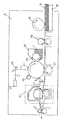
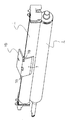
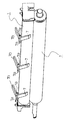
7は可動部材としての分離爪であり、フィルム5の外周面と対向する定着カバー(装置カバー)3に対して、例えば、図3のように加熱ユニット1の長手方向の略中央部等の位置に1個、図4のように加熱ユニット1の長手方向に沿って間隔をあけて2個以上複数個組付けて具備させることができる。なお、図3・図4は定着カバー3は省略して描いてある。
【0044】
上記の分離爪7はその上端側に設けた横軸部7aを定着カバー3側に設けた軸受部(不図示)に軸受保持させてあり、定着カバー3から加熱ユニット1のニップ部下流側(ニップ部よりも記録シート搬送方向下流側)に垂下状態にあり、横軸部7aを中心に揺動自由(回動可能)である。また、分離爪7の上端部は図面上右方に略直角折り曲げアーム部7bを具備させてあり、このアーム部7bの重量により分離爪7に横軸部7aを中心とする図面上時計方向への回動モーメントを生じさせている。そして定常状態(自由状態)では、アーム部7bは自重で横軸部7aを中心に時計方向に倒れ回動して定着カバー3の上面に設けた受け部3aに受け止められた状態にあり、この状態において分離爪7はその先端部が加熱ユニット1の薄耐熱フィルム5の表面から離間している。この状態時の薄耐熱フィルム5の表面と分離爪7の先端の隙間は0.2mmから5mmで、好ましくは0.5mmから2.5mmあれば良い。
【0045】
更には、薄耐熱フィルム5側の分離爪7の先端はR0.5mmの滑らかな形状をしている。
【0046】
定常状態においては、転写部でトナー像の転写を受けて定着器31に導入された記録シートSは定着器31のニップ部Nを挟持搬送されることで、薄耐熱フィルム5を介したヒータHからの熱とニップ圧力によりトナー像が記録シートに定着される。ニップ部Nを通過し、トナーにより薄耐熱フィルム5に密着している記録シートSは、ステイ6の分離変曲部9によって薄耐熱フィルム5から分離され、排紙ローラ対4へと搬送される。この状態時には分離爪7は加熱ユニット1の薄耐熱フィルム5の表面から離間した状態が維持されている。
【0047】
8は排紙センサフラグであり、定着ニップ部Nを出て定着フィルム5から分離されて排紙ローラ対4へと搬送される記録シートSとの接触で蹴り倒されることで不図示のセンサ部との協働で排紙ローラ対4を通過していく記録シートを検知する。
【0048】
すなわち、排紙センサフラグ8は記録シートが存在していないときは図2の実線示のように起立状態にあり、センサ部はOFF状態にある。記録シートが定着ニップ部Nから排紙ローラ対4へと搬送されるとその記録シートの先端で2点鎖線示のように蹴り倒されて記録シートの後端が通過するまでその蹴り倒しの状態にあり、その間センサ部がON状態に保持される。制御部(不図示)はセンサ部のOFF信号で記録シート無しを検知し、ON信号で記録シート有りを検知する。
【0049】
制御部は、センサ部のON信号の継続時間が所定の範囲内であるときは記録シートが正常に排出搬送されたと認識する。ON信号の継続時間が所定の範囲を越えた場合には定着ニップ部Nと排紙ローラ対4との間において記録シートのジャムが生じたと認識して、制御部は加圧ローラユニット駆動手段Mを含むプリンタ駆動手段を緊急停止させ、表示部にジャム発生の表示をし、操作者にジャム処理を促す。
【0050】
このような構成において、何らかの原因で記録シートSが排紙ローラ対4から先に搬送されなくなると、定着カバー3内で、かつ、排紙ローラ対4とニップ部Nの間で記録シートSがアコーディオン状になり、そのジャムした記録シート部分が分離爪7の外面側(分離爪7の加熱ユニット1側とは反対側の面)に接触して押圧することで、該分離爪7が横軸部7aを中心に、アーム部7bの自重による時計方向の回動モーメントに抗して反時計方向に加熱ユニット1側へ回転しはじめ、最後には分離爪7のR0.5mmの滑らかな先端と加熱ユニット1の薄耐熱フィルム5の表面が当接する。
【0051】
更に記録シートSが搬送されると記録シートSの行き場がなくなり、ついには分離変曲部9で記録シートSと薄耐熱フィルム5が分離されず、トナーを介して記録シートSが薄耐熱フィルム5に密着し巻付きはじめる。
【0052】
巻付きはじめた記録シートSは加熱ユニット1の薄耐熱フィルム5の表面に当接した分離爪7により薄耐熱フィルム5から一部分離され、巻付きを防止する。
【0053】
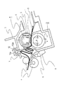
図5は上記の記録シートSのジャム状態を示した図である。分離爪7はジャムした記録シート部分が分離爪外面に接触して押圧することで、横軸部7aを中心に反時計方向に回動してその先端部が加熱ユニット1の薄耐熱フィルム5の表面に当接しており、アーム部7bは定着カバー3の上面の受け部3aから持ち上げられて浮いている状態になっている。
【0054】
行き場がなくなった記録シートSが更に搬送されてくると、分離爪7の下部で小さいアコーディオン状態になるか、または、ニップ部Nでスリップする。
上記のように、可動部材としての分離爪7は、ニップ部Nよりもフィルム回転方向下流側にフィルム5に対して接離可能であり、画像加熱処理を行っていない時及び正常な画像加熱処理中はフィルム5から離間しており、ニップ部Nよりも記録シート搬送方向下流側で記録シートSのジャムが発生するとジャムした記録シートで押されて回動してフィルム5に当接し記録シートのフィルム5への巻き付きの拡大を抑える。
【0055】
制御部のジャム検知による、加圧ローラユニット駆動手段Mを含むプリンタ駆動手段の緊急停止は、上述したように排紙センサフラグ8の蹴り倒しに基づくセンサ部のON信号の継続時間が所定の範囲を越えた時点でなされる。
【0056】
次にジャム処理について説明する。アコーディオン状態になった記録シートSを排紙ローラ対4より下流側から引き出すと、図6のように定着カバー3内の下流側のアコーディオン部がなくなり、分離爪7はアーム部7bの自重により定常状態位置に復帰する。
【0057】
記録シートSはその後も無理なく排紙ローラ対4側から引き出せ、ジャムシートが破れることなくジャム処理が可能になる。
【0058】
上記のようにジャムした記録シートを除去した後に、プリンタのリセット処置をすることで、プリント再開が可能になる。
【0059】
以上のように本実施形態によれば、通常定着時に分離爪7は加熱ユニット1の薄耐熱フィルム5に接することなく配置され、ジャムが発生してはじめて分離爪7が薄耐熱フィルム5に接するため、薄耐熱フィルム5に無理な力をかけずにすみ、薄耐熱フィルム5に傷や過度の摩耗及び、分離爪7のトナー汚れを極力小さくし、簡単でかつ、比較的安価な機構で加熱ユニット1への巻付きを防止し、ユーザが簡単な手順通りジャム処理を行うことが可能になる。また、分離爪7の配設方法が簡単で、かつ、定着カバー3上から分離爪7を配設しているため、加熱ユニット1に傷付けることなく簡単に分離爪7を組付けることが可能になる。
【0060】
更には、分離爪7の先端はR0.5mmの滑らかな形状であるため、より一層、薄耐熱フィルム5への傷を防止することが可能になる。
【0061】
<第2の実施形態>
図7〜図9は本実施形態例の定着器31の概略構成図である。
【0062】
この定着器31は前記第1の実施形態の定着器31において、分離爪7の定常状態時とジャム発生時の姿勢変化からジャムを検知するジャム検知センサ10を具備させ、該センサ10によるジャム検知にて加圧ローラユニット駆動手段Mを含むプリンタ駆動手段を停止させる構成にしたものである。
【0063】
その他の定着器構成・プリンタ構成は第1の実施形態例のものと同様であるから同様の構成部材・部分には同じ符号を付して再度の説明を省略する。
【0064】
ジャム検知センサ10は例えばフォト・カプラーであり、定着カバー3の上面に配設してある。このジャム検知センサ10に対して分離爪7の略直角折り曲げアーム部7bの先端部7cをセンサフラグとして関与させている。
【0065】
即ち、分離爪7のアーム部7bは、前述したように、定常状態時には自重で横軸部7aを中心に時計方向に倒れ回動して定着カバー3の上面に設けた受け部3aに受け止められた回動姿勢状態にあり、ジャム検知センサとしてのフォト・カプラー10はこの回動姿勢状態のアーム部7bの先端フラグ部7cでセンサ光路が遮断されてOFF状態にされている(図7)。
【0066】
ジャム発生時は、前述したように、分離爪7はジャムした記録シート部分が分離爪外面に接触して押圧することで、横軸部7aを中心に反時計方向に回動してその先端部が加熱ユニット1の薄耐熱フィルム5の表面に当接し、アーム部7bは定着カバー3の上面の受け部3aから持ち上げられて浮いた状態になることで、アーム部7bの先端フラグ部7cがフォト・カプラー10のセンサ光路から逃げ移動する。これによりフォト・カプラー10はセンサ光路の開放でON状態になる(図8)。
このように本実施例では、可動部材である分離爪7の一部7cが前記センサ10に作用するセンサフラグとなっており、分離爪7がジャムした記録シートで押されてフィルム5に当接すると、センサ10に対するセンサフラグ7cの作用状態が画像加熱処理を行っていない時及び正常な画像加熱処理中とは異なる状態に変化する。
【0067】
フォト・カプラー10のON信号がジャム検知信号であり、制御回路100はこのジャム検知信号に基づいて加圧ローラユニット駆動手段Mを含むプリンタ駆動手段を緊急停止させる。
【0068】
これにより、記録シートSは駆動手段Mのイナーシャ分だけ搬送され停止する。このように、ジャム検知後すぐに駆動手段Mが停止されるため、前記第1の実施形態よりも薄耐熱フィルム5に対するストレスが小さい。
【0069】
次にジャム処理について説明する。アコーディオン状態になった記録シートSを排紙ローラ対4より下流側から引き出すと、図9のように定着カバー3内の下流側のアコーディオン部がなくなり、分離爪7はアーム部7bの自重により定常状態位置に復帰し、ジャム検知センサとしてのフォト・カプラー10はセンサ光路がアーム部7bの先端フラグ部7cにより遮断され、フォト・カプラー10はOFFに復帰する。
【0070】
記録シートSはその後も無理なく排紙ローラ対4側から引き出せ、ジャムシートが破れることなくジャム処理が可能になる。
【0071】
上記のようにジャムした記録シートを除去した後に、プリンタのリセット処置をすることで、プリント再開が可能になる。
【0072】
以上のように本実施形態によれば、通常定着時に分離爪7は薄耐熱フィルム5に接することなく配置され、ジャムが発生してはじめて分離爪7の滑らかな先端が薄耐熱フィルム5に接し、かつ、ジャム検知により駆動手段Mを停止することにより、薄耐熱フィルム7に無理な力をかけずにすみ、薄耐熱フィルム5に傷や過度の摩耗及び、分離爪7のトナー汚れを極力小さくし、簡単でかつ、比較的安価な機構で加熱ユニット1への巻付きを防止し、ユーザが簡単な手順通りジャム処理を行うことが可能になる。
【0073】
ジャム検知センサ10はフォト・カプラーに限らず、マイクロスイッチなど他のセンサ・リレー類を使用することができる。
【0074】
<第3の実施形態>
図10〜図12は本実施形態例の定着器31の概略構成図である。
【0075】
この定着器31は前記第1の実施形態の定着器31において、分離爪7の上端部にスライダ頭部7d設け、そのスライダ頭部7dを定着カバー3に設けたスリット穴部材12のスリット穴12aに係合させて保持させて、分離爪7を定着カバー3から加熱ユニット1のニップ部下流側(ニップ部よりも記録シート搬送方向下流側)に垂下させてある。
【0076】
スリット穴12aは記録シート搬送方向を長手とし、左下がりに傾斜させてある。傾斜は角度的には15°以上が望ましい。
【0077】
分離爪7のスライダ頭部7dはスリット穴12aの長手に沿ってスライド移動自由(スライド可能)である。即ち、分離爪7がスリット穴12aに対するスライダ頭部7dのスライド移動で加熱ユニット1に対して接離方向に直線状に移動可能である。
【0078】
その他の定着器構成・プリンタ構成は第1の実施形態例のものと同様であるから同様の構成部材・部分には同じ符号を付して再度の説明を省略する。
【0079】
分離爪7は、定常状態においては、図10のように頭部7dが傾斜スリット穴12aの傾斜面を自重により滑り下ってその側のスリット穴端部に受け止められた位置に保持されて、分離爪7はその先端部が加熱ユニット1の薄耐熱フィルム5の表面から離間している。
【0080】
このような構成において、何らかの原因で記録シートSが排紙ローラ対4から先に搬送されなくなると、定着カバー3内で、かつ、排紙ローラ対4とニップ部Nの間で記録シートSがアコーディオン状になり、そのジャムした記録シート部分が分離爪7の外面側(分離爪7の加熱ユニット1側とは反対側の面)に接触して押圧することで、該分離爪7がその自重に抗して押し動かされてスリット穴12aに沿って加熱ユニット1側へ移動しはじめ、最後には分離爪7のR0.5mmの滑らかな先端と加熱ユニット1の薄耐熱フィルム5の表面が当接する。即ち、可動部材である分離爪7はジャムした記録シートに押されてスライドしてフィルム5に当接する。
【0081】
更に記録シートSが搬送されると記録シートSの行き場がなくなり、ついには分離変曲部9で記録シートSと薄耐熱フィルム5が分離されず、トナーを介して記録シートSが薄耐熱フィルム5に密着し巻付きはじめる。
【0082】
巻付きはじめた記録シートSは加熱ユニット1の薄耐熱フィルム5の表面に当接した分離爪7により薄耐熱フィルム5から一部分離され、巻付きを防止する。
【0083】
図11は上記の記録シートSのジャム状態を示した図である。分離爪7はジャムした記録シート部分が分離爪外面に接触して押圧することで加熱ユニット1側へ自重に抗して押し動かされてその先端部が加熱ユニット1の薄耐熱フィルム5の表面に当接している状態になっている。
【0084】
行き場がなくなった記録シートSが更に搬送されてくると、分離爪7の下部で小さいアコーディオン状態になるか、または、ニップ部Nでスリップする。
【0085】
制御部のジャム検知による、加圧ローラユニット駆動手段Mを含むプリンタ駆動手段の緊急停止は、第一の実施形態で述べたように排紙センサフラグ8の蹴り倒しに基づくセンサ部のON信号の継続時間が所定の範囲を越えた時点でなされる。
【0086】
次にジャム処理について説明する。アコーディオン状態になった記録シートSを排紙ローラ対4より下流側から引き出すと、図12のように定着カバー3内の下流側のアコーディオン部がなくなり、分離爪7は、頭部7dが傾斜スリット穴12aの傾斜面を自重により滑り下ってその側のスリット穴端部に受け止められた位置に保持されて、分離爪先端部が加熱ユニット1の薄耐熱フィルム5の表面から離間している定常状態位置に復帰する。
【0087】
記録シートSはその後も無理なく排紙ローラ対4側から引き出せ、ジャムシートが破れることなくジャム処理が可能になる。
【0088】
上記のようにジャムした記録シートを除去した後に、プリンタのリセット処置をすることで、プリント再開が可能になる。
【0089】
以上のように本実施形態によれば、通常定着時に分離爪7は加熱ユニット1の薄耐熱フィルム5に接することなく配置され、ジャムが発生してはじめて分離爪7が薄耐熱フィルム5に接するため、薄耐熱フィルム5に無理な力をかけずにすみ、薄耐熱フィルム5に傷や過度の摩耗及び、分離爪7のトナー汚れを極力小さくし、簡単でかつ、比較的安価な機構で加熱ユニット1への巻付きを防止し、ユーザが簡単な手順通りジャム処理を行うことが可能になる。また、分離爪7の配設方法が簡単で、かつ、定着カバー3上から分離爪7を配設しているため、加熱ユニット1に傷付けることなく簡単に分離爪7を組付けることが可能になる。
【0090】
更には、分離爪7の先端はR0.5mmの滑らかな形状であるため、より一層、薄耐熱フィルム5への傷を防止することが可能になる。
【0091】
【0092】
<その他>
1)各実施形態の像加熱装置は定着器であるが、本発明の像加熱装置には、定着器だけでなく、仮定着処理、つや等の表面性改質処理などする像加熱装置も含まれる。
【0093】
2)電磁誘導加熱方式など他の加熱方式の像加熱装置にも本発明は適用できることは勿論である。
【0094】
3)記録シートに対する画像形成原理・プロセス・方式は転写式電子写真方式に限られないことは勿論である。感光紙や静電記録紙等を用いた直接方式での画像形成方式であってもよいし、静電記録方式・磁気記録方式等であってもよい。
【0095】
【発明の効果】
以上説明したように本発明によれば、記録シートが加熱ユニットのフィルムに巻付くことを防止し、装置にダメージを与えることなく、容易にジャム処理できる像加熱装置を提供することができる。
【図面の簡単な説明】
【図1】 第1の実施形態における画像形成装置例の概略構成図
【図2】 定着器の模式断面図
【図3】 分離爪の配設形態を示した模式図(その1)
【図4】 分離爪の配設形態を示した模式図(その2)
【図5】 ジャム状態時の模式断面図
【図6】 ジャム処理時の模式断面図
【図7】 第2の実施形態における定着器の模式断面図
【図8】 ジャム状態時の模式断面図
【図9】 ジャム処理時の模式断面図
【図10】 第3の実施形態における定着器の模式断面図
【図11】 ジャム状態時の模式断面図
【図12】 ジャム処理時の模式断面図
【図13】 従来例の定着器を示す模式断面図
【図14】 加熱ユニットに記録シートが巻付いた状態を示す模式断面図
【図15】 巻付いた記録シート上のトナーとトナーが接着することの説明図
【図16】 従来例の巻付き対策を示す模式断面図
【図17】 従来例の巻付き対策で巻付きが発生した状態を示す模式断面図
【符号の説明】
1 加熱ユニット
2 加圧ローラユニット
3 定着カバー
4 排紙ローラ対
5 薄耐熱フィルム
6 ステイ
7 分離爪
8 排紙センサフラグ
9 分離変曲部
10 ジャム検知センサ
H ヒータ
N ニップ部
R 巻付き防止リブ
S 記録シート
T トナー[0001]
BACKGROUND OF THE INVENTION
The present invention provides an image heating apparatus.In placeIt is related.
[0002]
More detailsA cylindrical film; a heating body that contacts the inner surface of the film; and a pressure roller that forms a nip portion with the heating body via the film, and sandwiches and conveys the recording sheet at the nip portion. WhileHeat the image on the recording sheet (fixing process, hypothetical attachment process, surface modification process such as gloss)StatueHeating equipmentIn placeIt is related.
[0003]
[Prior art]
For example, in a transfer-type electrophotographic image forming apparatus, a toner image fixing device for a recording sheet to which a toner image has been transferred is equipped with the image heating device as described above. When the recording sheet conveyance destination is interrupted and the recording sheet is cut off, the destination of the recording sheet is lost, and the recording sheet is wound around the heating unit, which makes it difficult to handle the jam.
[0004]
For this reason, various techniques have heretofore been disclosed in order to solve the above problems. For example, techniques described in JP-A-10-74015, JP-A-9-236958 and the like can be mentioned.
[0005]
Japanese Patent Application Laid-Open No. 10-74015 discloses a “fixing device in an image forming apparatus” that urges a separation claw in a direction in which it is always pressed against a fixing roller as a heating unit by a spring, and the separation claw is moved in the outer circumferential direction of the fixing roller by jammed paper Then, the movement of the separation claw is detected by the sensor, and the winding of the recording sheet is detected.
[0006]
Japanese Patent Application Laid-Open No. 9-236958 discloses an “image forming apparatus” which is a torque value detected by a torque detection means for detecting a load torque of a heating roller, which is disposed between a driving device and a heating roller as a heating unit. Thus, winding of the recording sheet is detected.
[0007]
FIG.Fig. 1 shows a schematic configuration diagram of an example of a film heating type, pressure roller driving type, and tensionless type image heating apparatus using a cylindrical thin heat-resistant film. This image heating apparatus is described in, for example, Japanese Patent Application Laid-Open No. 4-44075 to 44033.
[0008]
[0009]
[0010]
The
[0011]
The
[0012]
The
[0013]
The
[0014]
The recording sheet S having a curvature separated from the thin heat-
[0015]
Further, since the
[0016]
In such an image heating apparatus,FIG.As shown in FIG. 4, when a jam occurs for some reason and the recording sheet S is in an accordion state inside the
[0017]
for that reason,FIG.As described above, the rib R is provided on the wall of the
[0018]
[Problems to be solved by the invention]
Each of the above-described prior arts is effective in preventing the recording sheet S from being wound around the
[0019]
That is, as described above, the one disclosed in Japanese Patent Application Laid-Open No. 10-74015 requires a support shaft and a lever member for detecting a spring and a winding for pressing a separation claw against a fixing roller as a heating unit. The structure is complicated. Also, since the spring is always urged by the spring in the direction in which the separation claw is pressed against the fixing roller, a small amount of toner adhering to the fixing roller adheres to the tip of the separation claw and is laminated, and the laminated toner adheres to the fixing roller again Then, it is necessary to use an expensive material in which image contamination occurs on the recording sheet or toner does not adhere. Further, since the separation claw is always urged by the fixing roller, it is necessary to select a special and expensive material that has high heat resistance and prevents damage to the fixing roller. Further, since the separation claw is always urged against the fixing roller, there is a problem that the fixing roller is easily damaged during assembly.
[0020]
Further, as described in Japanese Patent Laid-Open No. 9-236958, as described above, it is detected by the torque detection means that detects the load torque of the heating roller disposed between the driving device and the heating roller as the heating unit. However, if the heating roller is reduced in diameter and speeded up for efficiency of heat transfer, the operation of the drive device is stopped after torque detection. However, the recording sheet is conveyed by the inertia of the heating roller or the like, and finally, it is difficult to wind the jammed paper around the heating roller.
[0021]
Also,FIG.In the image heating apparatus of the film heating method shown in FIG. 4, even if the gap t is set narrow as described above, the thin heat-
[0022]
The present invention has been made in order to solve the above-described problems, and prevents the recording sheet from being wound around the heating unit, so that it can be easily jammed.SetThe purpose is to provide.
[0023]
[Means for Solving the Problems]
The present invention provides an image heating apparatus having the following configuration.In placeis there.
[0024]
(1) A cylindrical film, a heating body that contacts the inner surface of the film, and a pressure roller that forms a nip portion with the heating body via the film, and a recording sheet is formed at the nip portion. In an image heating apparatus that heat-processes an image on a recording sheet while nipping and conveying the film, the film is disposed downstream of the nip portion in the film rotation direction.Outer peripheral surfaceA movable member that can contact and separateThere is no member in contact with the outer peripheral surface of the film other than the movable member on the downstream side in the film rotation direction from the nip portion,The movable member is separated from the film when the image heating process is not performed and during a normal image heating process, and jammed when a recording sheet jam occurs on the downstream side in the recording sheet conveyance direction from the nip portion. The recording sheet is pressed against the film to suppress expansion of winding of the recording sheet around the film.
[0025]
(2)The movable member is pivotably or slidably attached to an apparatus cover facing the outer peripheral surface of the film, and the movable member is pressed by a jammed recording sheet and pivoted or slid to contact the film.(2) The image heating apparatus according to (1).
[0026]
(3)The apparatus further includes a sensor for detecting jamming of a recording sheet, a part of the movable member is a sensor flag that acts on the sensor, and the movable member is pressed by the jammed recording sheet to the film. Upon contact, the sensor flag action state on the sensor changes to a state different from when the image heating process is not performed and during normal image heating process.(2) The image heating apparatus according to (1).
[0027]
[0028]
[0029]
[0030]
[0031]
[0032]
[0033]
DETAILED DESCRIPTION OF THE INVENTION
An image heating apparatus to which the present invention is applied will be described below with reference to the drawings.PlaceAn image forming apparatus equipped as a fixing device will be described.
[0034]
<First Embodiment>
(A) Image forming apparatus example
FIG. 1 is a schematic configuration diagram of an example of an image forming apparatus provided with an image heating apparatus according to the present invention as a toner image fixing device. The image forming apparatus A of this example is a laser printer using a transfer type electrophotographic process.
[0035]
[0036]
The
[0037]
The electrostatic latent image formed on the
[0038]
[0039]
[0040]
The recording sheet S that has passed through the transfer nip is separated from the surface of the
[0041]
Further, the surface of the
[0042]
(B) Fixing
FIG. 2 is a schematic configuration diagram of a fixing
[0043]
7 isAs a movable memberSeparation nails,Opposite the outer peripheral surface of the film 5Fixing cover(Device cover)3, for example, one at a position such as a substantially central portion in the longitudinal direction of the
[0044]
The
[0045]
Furthermore, the tip of the
[0046]
In the steady state, the recording sheet S that has received the transfer of the toner image at the transfer portion and is introduced into the fixing
[0047]
[0048]
That is, when the recording sheet is not present, the paper
[0049]
The control unit recognizes that the recording sheet has been normally discharged and conveyed when the duration of the ON signal of the sensor unit is within a predetermined range. When the duration of the ON signal exceeds a predetermined range, the control unit recognizes that a recording sheet jam has occurred between the fixing nip portion N and the paper discharge roller pair 4, and the control unit presses the pressure roller unit driving unit M. The printer driving means including the emergency stop is stopped, the occurrence of jam is displayed on the display unit, and the operator is prompted to perform jam processing.
[0050]
In such a configuration, when the recording sheet S is not conveyed first from the paper discharge roller pair 4 for some reason, the recording sheet S is placed in the fixing
[0051]
When the recording sheet S is further conveyed, the recording sheet S has no place to go. Finally, the recording sheet S and the thin heat-
[0052]
The recording sheet S that has begun to be wound is partly separated from the thin heat-
[0053]
FIG. 5 is a diagram showing a jammed state of the recording sheet S described above. The
[0054]
When the recording sheet S having no destination is further conveyed, the recording sheet S enters a small accordion state below the
As described above, the
[0055]
The emergency stop of the printer driving means including the pressure roller unit driving means M based on the jam detection of the control part is a predetermined range of the ON time duration of the sensor part based on the kicking of the paper
[0056]
Next, jam processing will be described. When the recording sheet S in the accordion state is pulled out from the downstream side of the discharge roller pair 4, the downstream accordion part in the fixing
[0057]
Thereafter, the recording sheet S can be pulled out from the discharge roller pair 4 side without difficulty, and jamming can be performed without tearing the jammed sheet.
[0058]
After removing the jammed recording sheet as described above, the printer can be reset to restart printing.
[0059]
As described above, according to the present embodiment, the
[0060]
Furthermore, since the tip of the
[0061]
<Second Embodiment>
7 to 9 are schematic configuration diagrams of the fixing
[0062]
The fixing
[0063]
Since the other fixing device configuration and printer configuration are the same as those of the first embodiment, the same constituent members and parts are denoted by the same reference numerals and the description thereof is omitted.
[0064]
The
[0065]
That is, as described above, the
[0066]
When a jam occurs, as described above, the
As described above, in this embodiment, a part 7c of the
[0067]
The ON signal of the
[0068]
As a result, the recording sheet S is conveyed by the amount corresponding to the inertia of the driving means M and stopped. Thus, since the driving means M is stopped immediately after the jam detection, the stress on the thin heat-
[0069]
Next, jam processing will be described. When the recording sheet S in the accordion state is pulled out from the downstream side of the discharge roller pair 4, the downstream accordion part in the fixing
[0070]
Thereafter, the recording sheet S can be pulled out from the discharge roller pair 4 side without difficulty, and jamming can be performed without tearing the jammed sheet.
[0071]
After removing the jammed recording sheet as described above, the printer can be reset to restart printing.
[0072]
As described above, according to the present embodiment, the
[0073]
The
[0074]
<Third Embodiment>
10 to 12 are schematic configuration diagrams of the fixing
[0075]
In the fixing
[0076]
The
[0077]
The
[0078]
Since the other fixing device configuration and printer configuration are the same as those of the first embodiment, the same constituent members and parts are denoted by the same reference numerals and the description thereof is omitted.
[0079]
In a steady state, the
[0080]
In such a configuration, when the recording sheet S is not conveyed first from the paper discharge roller pair 4 for some reason, the recording sheet S is placed in the fixing
[0081]
When the recording sheet S is further conveyed, the recording sheet S has no place to go. Finally, the recording sheet S and the thin heat-
[0082]
The recording sheet S that has begun to be wound is partly separated from the thin heat-
[0083]
FIG. 11 is a diagram showing a jammed state of the recording sheet S described above. The
[0084]
When the recording sheet S having no destination is further conveyed, the recording sheet S enters a small accordion state below the
[0085]
The emergency stop of the printer driving means including the pressure roller unit driving means M due to the jam detection of the control part is the ON signal of the sensor part based on the kicking of the paper
[0086]
Next, jam processing will be described. When the recording sheet S in the accordion state is pulled out from the downstream side of the discharge roller pair 4, the downstream accordion portion in the fixing
[0087]
Thereafter, the recording sheet S can be pulled out from the discharge roller pair 4 side without difficulty, and jamming can be performed without tearing the jammed sheet.
[0088]
After removing the jammed recording sheet as described above, the printer can be reset to restart printing.
[0089]
As described above, according to the present embodiment, the
[0090]
Furthermore, since the tip of the
[0091]
[0092]
<Others>
1) Although the image heating device of each embodiment is a fixing device, the image heating device of the present invention includes not only a fixing device but also an image heating device that performs a surface property modification process such as a hypothetical process and a gloss. It is.
[0093]
2) Of course, the present invention can be applied to an image heating apparatus of another heating method such as an electromagnetic induction heating method.
[0094]
3) The image forming principle, process, and method for the recording sheet are not limited to the transfer type electrophotographic method. A direct image forming method using photosensitive paper, electrostatic recording paper, or the like may be used, or an electrostatic recording method, a magnetic recording method, or the like may be used.
[0095]
【The invention's effect】
As described above, according to the present invention, the recording sheet is a heating unit.FilmAn image heating device that can be easily jammed without damaging the device and damaging the devicePlaceCan be provided.
[Brief description of the drawings]
FIG. 1 is a schematic configuration diagram of an example of an image forming apparatus according to a first embodiment.
FIG. 2 is a schematic sectional view of a fixing device.
FIG. 3 is a schematic diagram showing an arrangement of separation claws (part 1).
FIG. 4 is a schematic diagram showing the arrangement of separation claws (Part 2).
FIG. 5 is a schematic sectional view in a jam state.
FIG. 6 is a schematic cross-sectional view during jam processing.
FIG. 7 is a schematic cross-sectional view of a fixing device according to a second embodiment.
FIG. 8 is a schematic cross-sectional view in a jam state.
FIG. 9 is a schematic cross-sectional view during jam processing.
FIG. 10 is a schematic cross-sectional view of a fixing device according to a third embodiment.
FIG. 11 is a schematic sectional view in a jam state.
FIG. 12 is a schematic sectional view during jam processing.
FIG. 13 is a schematic cross-sectional view showing a conventional fixing device.
FIG. 14 is a schematic cross-sectional view showing a state where a recording sheet is wound around a heating unit.
FIG. 15 is an explanatory diagram of toner adhering on a wound recording sheet
FIG. 16 is a schematic cross-sectional view showing a winding countermeasure of a conventional example.
FIG. 17 is a schematic cross-sectional view showing a state where winding has occurred as a result of conventional winding measures
[Explanation of symbols]
1 Heating unit
2 Pressure roller unit
3 Fixing cover
4 Paper discharge roller pair
5 Thin heat-resistant film
6 Stay
7 Separating nails
8 Paper discharge sensor flag
9 Separation inflection part
10 Jam detection sensor
H heater
N Nip part
R Winding prevention rib
S Recording sheet
T Toner
Claims (3)
前記ニップ部よりもフィルム回転方向下流側に前記フィルムの外周面に対して接離可能な可動部材を有し、前記ニップ部よりもフィルム回転方向下流側には前記可動部材以外に前記フィルムの外周面に接触する部材は無く、前記可動部材は、画像加熱処理を行っていない時及び正常な画像加熱処理中は前記フィルムから離間しており、前記ニップ部よりも記録シート搬送方向下流側で記録シートのジャムが発生するとジャムした記録シートで押されて前記フィルムに当接し記録シートの前記フィルムへの巻き付きの拡大を抑えることを特徴とする像加熱装置。A cylindrical film; a heating body that contacts the inner surface of the film; and a pressure roller that forms a nip portion with the heating body via the film, and sandwiches and conveys the recording sheet at the nip portion. While in the image heating apparatus that heat-processes the image on the recording sheet,
There is a movable member that is movable toward and away from the outer peripheral surface of the film at the downstream side in the film rotation direction from the nip portion, and the outer periphery of the film other than the movable member at the downstream side in the film rotation direction from the nip portion There is no member in contact with the surface, and the movable member is separated from the film when image heating processing is not being performed and during normal image heating processing, and recording is performed downstream of the nip portion in the recording sheet conveyance direction. An image heating apparatus, wherein when a sheet jam occurs, the image is pressed by the jammed recording sheet and abuts against the film to suppress an increase in winding of the recording sheet around the film.
Priority Applications (5)
| Application Number | Priority Date | Filing Date | Title |
|---|---|---|---|
| JP2000291027A JP4579393B2 (en) | 2000-09-25 | 2000-09-25 | Image heating device |
| US09/953,951 US6615017B2 (en) | 2000-09-25 | 2001-09-18 | Image forming apparatus capable of preventing recording material from being twined |
| KR10-2001-0058917A KR100421404B1 (en) | 2000-09-25 | 2001-09-24 | Image heating apparatus |
| EP01122866.5A EP1191404B1 (en) | 2000-09-25 | 2001-09-24 | Image heating apparatus |
| CNB011408898A CN1158579C (en) | 2000-09-25 | 2001-09-25 | Picture heating device |
Applications Claiming Priority (1)
| Application Number | Priority Date | Filing Date | Title |
|---|---|---|---|
| JP2000291027A JP4579393B2 (en) | 2000-09-25 | 2000-09-25 | Image heating device |
Publications (3)
| Publication Number | Publication Date |
|---|---|
| JP2002099174A JP2002099174A (en) | 2002-04-05 |
| JP2002099174A5 JP2002099174A5 (en) | 2007-11-08 |
| JP4579393B2 true JP4579393B2 (en) | 2010-11-10 |
Family
ID=18774170
Family Applications (1)
| Application Number | Title | Priority Date | Filing Date |
|---|---|---|---|
| JP2000291027A Expired - Fee Related JP4579393B2 (en) | 2000-09-25 | 2000-09-25 | Image heating device |
Country Status (5)
| Country | Link |
|---|---|
| US (1) | US6615017B2 (en) |
| EP (1) | EP1191404B1 (en) |
| JP (1) | JP4579393B2 (en) |
| KR (1) | KR100421404B1 (en) |
| CN (1) | CN1158579C (en) |
Families Citing this family (32)
| Publication number | Priority date | Publication date | Assignee | Title |
|---|---|---|---|---|
| JP2004184814A (en) * | 2002-12-05 | 2004-07-02 | Canon Inc | Heating device |
| JP4160841B2 (en) * | 2003-02-19 | 2008-10-08 | 松下電器産業株式会社 | Fixing jam detection device and image forming apparatus having the same |
| JP2005031348A (en) * | 2003-07-11 | 2005-02-03 | Toshiba Corp | Fixing device |
| US20050008408A1 (en) * | 2003-07-11 | 2005-01-13 | Kabushiki Kaisha Toshiba | Fixing device and image forming apparatus |
| JP2005091545A (en) * | 2003-09-16 | 2005-04-07 | Brother Ind Ltd | Fixing device and image forming apparatus |
| US7070181B2 (en) * | 2003-12-22 | 2006-07-04 | Xerox Corporation | Systems and methods for detecting bi-directional passage of an object via an articulated flag member arrangement |
| JP2005345687A (en) * | 2004-06-02 | 2005-12-15 | Konica Minolta Business Technologies Inc | Image forming apparatus |
| JP2007256821A (en) * | 2006-03-24 | 2007-10-04 | Kyocera Mita Corp | Fixing device for image forming apparatus |
| JP5084226B2 (en) * | 2006-11-08 | 2012-11-28 | キヤノン株式会社 | Fixing apparatus and image forming apparatus |
| US20090080952A1 (en) * | 2007-09-25 | 2009-03-26 | Russell Edward Lucas | Belt Fuser Assembly Having Feature To Prevent Media Wrapping Of The Fuser Belt |
| CN101422980B (en) * | 2007-11-02 | 2014-05-07 | 致伸科技股份有限公司 | Film pressing device with rubber-film detection mechanism |
| US20100322684A1 (en) * | 2009-06-19 | 2010-12-23 | Kabushiki Kaisha Toshiba | Fuser for image forming apparatus |
| JP2011043666A (en) * | 2009-08-21 | 2011-03-03 | Ricoh Co Ltd | Fixing device and image forming apparatus |
| JP2011064773A (en) * | 2009-09-15 | 2011-03-31 | Brother Industries Ltd | Image forming apparatus |
| CN102033470A (en) * | 2009-09-29 | 2011-04-27 | 株式会社东芝 | Fixing device, image forming apparatus, and method of removing residual toner |
| JP5018853B2 (en) * | 2009-09-29 | 2012-09-05 | ブラザー工業株式会社 | Image forming apparatus |
| JP5574748B2 (en) * | 2010-02-24 | 2014-08-20 | キヤノン株式会社 | Fixing apparatus and image forming apparatus |
| JP5436295B2 (en) * | 2010-03-26 | 2014-03-05 | キヤノン株式会社 | Fixing device |
| CN102213938A (en) * | 2010-04-05 | 2011-10-12 | 株式会社东芝 | Image forming apparatus and method of adjusting gap |
| JP5471995B2 (en) * | 2010-09-14 | 2014-04-16 | コニカミノルタ株式会社 | Fixing device, image forming apparatus |
| JP5360128B2 (en) * | 2011-05-06 | 2013-12-04 | コニカミノルタ株式会社 | Fixing apparatus and image forming apparatus |
| JP2014002243A (en) * | 2012-06-18 | 2014-01-09 | Ricoh Co Ltd | Fixation device and image formation device including the same |
| JP6202950B2 (en) * | 2013-09-02 | 2017-09-27 | キヤノン株式会社 | Image heating device |
| JP6109030B2 (en) * | 2013-09-27 | 2017-04-05 | 京セラドキュメントソリューションズ株式会社 | Image forming apparatus |
| US20160209789A1 (en) * | 2015-01-19 | 2016-07-21 | Ricoh Company, Ltd. | Sheet separation device, fixing device, and image forming apparatus |
| JP6597322B2 (en) * | 2016-01-08 | 2019-10-30 | コニカミノルタ株式会社 | Fixing apparatus and image forming apparatus |
| TWI604285B (en) * | 2016-03-09 | 2017-11-01 | 虹光精密工業股份有限公司 | Fixation module with separation claw detecting mechanism and printing apparatus using the same |
| JP2018034460A (en) * | 2016-09-01 | 2018-03-08 | 東芝テック株式会社 | Printer |
| US10768569B2 (en) | 2017-02-10 | 2020-09-08 | Canon Kabushiki Kaisha | Fixing device and image forming apparatus |
| JP6686937B2 (en) * | 2017-03-01 | 2020-04-22 | 京セラドキュメントソリューションズ株式会社 | Fixing device and image forming apparatus |
| JP7005233B2 (en) * | 2017-08-31 | 2022-01-21 | キヤノン株式会社 | Image forming device |
| JP2023072225A (en) * | 2021-11-12 | 2023-05-24 | キヤノン株式会社 | Image forming apparatus |
Citations (5)
| Publication number | Priority date | Publication date | Assignee | Title |
|---|---|---|---|---|
| JPH05307336A (en) * | 1992-04-30 | 1993-11-19 | Ricoh Co Ltd | Separation pawl for fixing device |
| JPH0968882A (en) * | 1995-08-31 | 1997-03-11 | Canon Inc | Fixing device |
| JPH10111620A (en) * | 1996-10-04 | 1998-04-28 | Ricoh Co Ltd | Fixing device |
| JPH10333465A (en) * | 1997-05-27 | 1998-12-18 | Canon Inc | Image forming device |
| JP2000219383A (en) * | 1999-01-29 | 2000-08-08 | Canon Inc | Sheet carrier, fixing apparatus and image forming device |
Family Cites Families (15)
| Publication number | Priority date | Publication date | Assignee | Title |
|---|---|---|---|---|
| US4065120A (en) * | 1975-10-17 | 1977-12-27 | Minolta Camera Kabushiki Kaisha | Copy paper stripping means |
| JPS587167A (en) * | 1981-07-07 | 1983-01-14 | Ricoh Co Ltd | Fixing device |
| JPS6460553A (en) * | 1987-08-27 | 1989-03-07 | Toshiba Corp | Paper sheet conveyer in picture forming device |
| AU645060B2 (en) * | 1990-03-06 | 1994-01-06 | Asahi Kogaku Kogyo Kabushiki Kaisha | Heat roll fixing unit |
| DE69117806T2 (en) | 1990-06-11 | 1996-08-22 | Canon Kk | Heater with continuous film |
| JP2884714B2 (en) | 1990-06-11 | 1999-04-19 | キヤノン株式会社 | Image heating device |
| JPH0444033A (en) | 1990-06-12 | 1992-02-13 | Fuji Photo Film Co Ltd | Silver halide photographic sensitive material |
| JPH04181977A (en) * | 1990-11-16 | 1992-06-29 | Sharp Corp | Image forming device |
| JP3252501B2 (en) * | 1992-12-02 | 2002-02-04 | キヤノン株式会社 | Image forming device |
| JPH09236958A (en) | 1996-03-01 | 1997-09-09 | Ricoh Co Ltd | Image forming device |
| JPH1074015A (en) | 1996-08-30 | 1998-03-17 | Ricoh Co Ltd | Fixing device in image forming device |
| JPH10319774A (en) * | 1997-05-14 | 1998-12-04 | Canon Inc | Image fixing device, its energizing method and image forming device used therewith |
| JP3622526B2 (en) * | 1997-10-16 | 2005-02-23 | 富士ゼロックス株式会社 | Image recording device |
| JP3923670B2 (en) * | 1998-11-20 | 2007-06-06 | 株式会社沖データ | Fixing device |
| JP2000275992A (en) * | 1999-03-23 | 2000-10-06 | Canon Inc | Image forming device |
-
2000
- 2000-09-25 JP JP2000291027A patent/JP4579393B2/en not_active Expired - Fee Related
-
2001
- 2001-09-18 US US09/953,951 patent/US6615017B2/en not_active Expired - Lifetime
- 2001-09-24 KR KR10-2001-0058917A patent/KR100421404B1/en active IP Right Grant
- 2001-09-24 EP EP01122866.5A patent/EP1191404B1/en not_active Expired - Lifetime
- 2001-09-25 CN CNB011408898A patent/CN1158579C/en not_active Expired - Fee Related
Patent Citations (5)
| Publication number | Priority date | Publication date | Assignee | Title |
|---|---|---|---|---|
| JPH05307336A (en) * | 1992-04-30 | 1993-11-19 | Ricoh Co Ltd | Separation pawl for fixing device |
| JPH0968882A (en) * | 1995-08-31 | 1997-03-11 | Canon Inc | Fixing device |
| JPH10111620A (en) * | 1996-10-04 | 1998-04-28 | Ricoh Co Ltd | Fixing device |
| JPH10333465A (en) * | 1997-05-27 | 1998-12-18 | Canon Inc | Image forming device |
| JP2000219383A (en) * | 1999-01-29 | 2000-08-08 | Canon Inc | Sheet carrier, fixing apparatus and image forming device |
Also Published As
| Publication number | Publication date |
|---|---|
| EP1191404B1 (en) | 2016-01-06 |
| KR20020024539A (en) | 2002-03-30 |
| EP1191404A2 (en) | 2002-03-27 |
| CN1158579C (en) | 2004-07-21 |
| US6615017B2 (en) | 2003-09-02 |
| CN1347016A (en) | 2002-05-01 |
| US20020037186A1 (en) | 2002-03-28 |
| EP1191404A3 (en) | 2005-12-28 |
| JP2002099174A (en) | 2002-04-05 |
| KR100421404B1 (en) | 2004-03-09 |
Similar Documents
| Publication | Publication Date | Title |
|---|---|---|
| JP4579393B2 (en) | Image heating device | |
| JP5053786B2 (en) | Image forming apparatus | |
| JP3252501B2 (en) | Image forming device | |
| JP4701955B2 (en) | Image forming apparatus | |
| JP5309508B2 (en) | Fixing apparatus and image forming apparatus | |
| JP2009053564A (en) | Fixing device | |
| JP2007304180A (en) | Image heating device | |
| JP3907407B2 (en) | Fixing apparatus and image forming apparatus | |
| JP2005164895A (en) | Fixing device and image forming apparatus | |
| JP6584211B2 (en) | Image forming apparatus | |
| JP4684902B2 (en) | Image forming apparatus | |
| JP3920529B2 (en) | Fixing apparatus and image forming apparatus having the same | |
| JP2006240840A (en) | Image forming device | |
| JP2008122719A (en) | Image heating device and image forming apparatus | |
| JP6602029B2 (en) | Image forming apparatus | |
| JP7253144B2 (en) | Fixing device and image forming device | |
| JP4281411B2 (en) | Sheet detecting device, fixing device using the same, and image forming device | |
| JP3414927B2 (en) | Image forming device | |
| JP4645262B2 (en) | Fixing apparatus and image forming apparatus using the same | |
| JP3668182B2 (en) | Image forming apparatus | |
| JP2007286352A (en) | Fixing device and image forming apparatus | |
| JP2004233823A (en) | Image forming apparatus | |
| JP2003131512A (en) | Fixing device | |
| JP2004271962A (en) | Fixing device and image forming apparatus | |
| JP2001022218A (en) | Separation claw cleaner |
Legal Events
| Date | Code | Title | Description |
|---|---|---|---|
| A521 | Request for written amendment filed |
Free format text: JAPANESE INTERMEDIATE CODE: A523 Effective date: 20070925 |
|
| A621 | Written request for application examination |
Free format text: JAPANESE INTERMEDIATE CODE: A621 Effective date: 20070925 |
|
| A131 | Notification of reasons for refusal |
Free format text: JAPANESE INTERMEDIATE CODE: A131 Effective date: 20100406 |
|
| A521 | Request for written amendment filed |
Free format text: JAPANESE INTERMEDIATE CODE: A523 Effective date: 20100531 |
|
| TRDD | Decision of grant or rejection written | ||
| A01 | Written decision to grant a patent or to grant a registration (utility model) |
Free format text: JAPANESE INTERMEDIATE CODE: A01 Effective date: 20100824 |
|
| A01 | Written decision to grant a patent or to grant a registration (utility model) |
Free format text: JAPANESE INTERMEDIATE CODE: A01 |
|
| A61 | First payment of annual fees (during grant procedure) |
Free format text: JAPANESE INTERMEDIATE CODE: A61 Effective date: 20100826 |
|
| FPAY | Renewal fee payment (event date is renewal date of database) |
Free format text: PAYMENT UNTIL: 20130903 Year of fee payment: 3 |
|
| R150 | Certificate of patent or registration of utility model |
Free format text: JAPANESE INTERMEDIATE CODE: R150 Ref document number: 4579393 Country of ref document: JP Free format text: JAPANESE INTERMEDIATE CODE: R150 |
|
| RD03 | Notification of appointment of power of attorney |
Free format text: JAPANESE INTERMEDIATE CODE: R3D03 |
|
| LAPS | Cancellation because of no payment of annual fees |