JP4577681B2 - Driving method of plasma display panel - Google Patents
Driving method of plasma display panel Download PDFInfo
- Publication number
- JP4577681B2 JP4577681B2 JP2004223368A JP2004223368A JP4577681B2 JP 4577681 B2 JP4577681 B2 JP 4577681B2 JP 2004223368 A JP2004223368 A JP 2004223368A JP 2004223368 A JP2004223368 A JP 2004223368A JP 4577681 B2 JP4577681 B2 JP 4577681B2
- Authority
- JP
- Japan
- Prior art keywords
- electrode
- address
- period
- discharge
- sustain
- Prior art date
- Legal status (The legal status is an assumption and is not a legal conclusion. Google has not performed a legal analysis and makes no representation as to the accuracy of the status listed.)
- Expired - Fee Related
Links
Images


Classifications
-
- G—PHYSICS
- G09—EDUCATION; CRYPTOGRAPHY; DISPLAY; ADVERTISING; SEALS
- G09G—ARRANGEMENTS OR CIRCUITS FOR CONTROL OF INDICATING DEVICES USING STATIC MEANS TO PRESENT VARIABLE INFORMATION
- G09G3/00—Control arrangements or circuits, of interest only in connection with visual indicators other than cathode-ray tubes
- G09G3/20—Control arrangements or circuits, of interest only in connection with visual indicators other than cathode-ray tubes for presentation of an assembly of a number of characters, e.g. a page, by composing the assembly by combination of individual elements arranged in a matrix no fixed position being assigned to or needed to be assigned to the individual characters or partial characters
- G09G3/22—Control arrangements or circuits, of interest only in connection with visual indicators other than cathode-ray tubes for presentation of an assembly of a number of characters, e.g. a page, by composing the assembly by combination of individual elements arranged in a matrix no fixed position being assigned to or needed to be assigned to the individual characters or partial characters using controlled light sources
- G09G3/28—Control arrangements or circuits, of interest only in connection with visual indicators other than cathode-ray tubes for presentation of an assembly of a number of characters, e.g. a page, by composing the assembly by combination of individual elements arranged in a matrix no fixed position being assigned to or needed to be assigned to the individual characters or partial characters using controlled light sources using luminous gas-discharge panels, e.g. plasma panels
- G09G3/288—Control arrangements or circuits, of interest only in connection with visual indicators other than cathode-ray tubes for presentation of an assembly of a number of characters, e.g. a page, by composing the assembly by combination of individual elements arranged in a matrix no fixed position being assigned to or needed to be assigned to the individual characters or partial characters using controlled light sources using luminous gas-discharge panels, e.g. plasma panels using AC panels
- G09G3/291—Control arrangements or circuits, of interest only in connection with visual indicators other than cathode-ray tubes for presentation of an assembly of a number of characters, e.g. a page, by composing the assembly by combination of individual elements arranged in a matrix no fixed position being assigned to or needed to be assigned to the individual characters or partial characters using controlled light sources using luminous gas-discharge panels, e.g. plasma panels using AC panels controlling the gas discharge to control a cell condition, e.g. by means of specific pulse shapes
- G09G3/292—Control arrangements or circuits, of interest only in connection with visual indicators other than cathode-ray tubes for presentation of an assembly of a number of characters, e.g. a page, by composing the assembly by combination of individual elements arranged in a matrix no fixed position being assigned to or needed to be assigned to the individual characters or partial characters using controlled light sources using luminous gas-discharge panels, e.g. plasma panels using AC panels controlling the gas discharge to control a cell condition, e.g. by means of specific pulse shapes for reset discharge, priming discharge or erase discharge occurring in a phase other than addressing
- G09G3/2927—Details of initialising
-
- H—ELECTRICITY
- H01—ELECTRIC ELEMENTS
- H01J—ELECTRIC DISCHARGE TUBES OR DISCHARGE LAMPS
- H01J11/00—Gas-filled discharge tubes with alternating current induction of the discharge, e.g. alternating current plasma display panels [AC-PDP]; Gas-filled discharge tubes without any main electrode inside the vessel; Gas-filled discharge tubes with at least one main electrode outside the vessel
- H01J11/20—Constructional details
-
- G—PHYSICS
- G09—EDUCATION; CRYPTOGRAPHY; DISPLAY; ADVERTISING; SEALS
- G09G—ARRANGEMENTS OR CIRCUITS FOR CONTROL OF INDICATING DEVICES USING STATIC MEANS TO PRESENT VARIABLE INFORMATION
- G09G2310/00—Command of the display device
- G09G2310/06—Details of flat display driving waveforms
-
- G—PHYSICS
- G09—EDUCATION; CRYPTOGRAPHY; DISPLAY; ADVERTISING; SEALS
- G09G—ARRANGEMENTS OR CIRCUITS FOR CONTROL OF INDICATING DEVICES USING STATIC MEANS TO PRESENT VARIABLE INFORMATION
- G09G2320/00—Control of display operating conditions
- G09G2320/02—Improving the quality of display appearance
- G09G2320/0228—Increasing the driving margin in plasma displays
-
- G—PHYSICS
- G09—EDUCATION; CRYPTOGRAPHY; DISPLAY; ADVERTISING; SEALS
- G09G—ARRANGEMENTS OR CIRCUITS FOR CONTROL OF INDICATING DEVICES USING STATIC MEANS TO PRESENT VARIABLE INFORMATION
- G09G3/00—Control arrangements or circuits, of interest only in connection with visual indicators other than cathode-ray tubes
- G09G3/20—Control arrangements or circuits, of interest only in connection with visual indicators other than cathode-ray tubes for presentation of an assembly of a number of characters, e.g. a page, by composing the assembly by combination of individual elements arranged in a matrix no fixed position being assigned to or needed to be assigned to the individual characters or partial characters
- G09G3/22—Control arrangements or circuits, of interest only in connection with visual indicators other than cathode-ray tubes for presentation of an assembly of a number of characters, e.g. a page, by composing the assembly by combination of individual elements arranged in a matrix no fixed position being assigned to or needed to be assigned to the individual characters or partial characters using controlled light sources
- G09G3/28—Control arrangements or circuits, of interest only in connection with visual indicators other than cathode-ray tubes for presentation of an assembly of a number of characters, e.g. a page, by composing the assembly by combination of individual elements arranged in a matrix no fixed position being assigned to or needed to be assigned to the individual characters or partial characters using controlled light sources using luminous gas-discharge panels, e.g. plasma panels
- G09G3/288—Control arrangements or circuits, of interest only in connection with visual indicators other than cathode-ray tubes for presentation of an assembly of a number of characters, e.g. a page, by composing the assembly by combination of individual elements arranged in a matrix no fixed position being assigned to or needed to be assigned to the individual characters or partial characters using controlled light sources using luminous gas-discharge panels, e.g. plasma panels using AC panels
- G09G3/291—Control arrangements or circuits, of interest only in connection with visual indicators other than cathode-ray tubes for presentation of an assembly of a number of characters, e.g. a page, by composing the assembly by combination of individual elements arranged in a matrix no fixed position being assigned to or needed to be assigned to the individual characters or partial characters using controlled light sources using luminous gas-discharge panels, e.g. plasma panels using AC panels controlling the gas discharge to control a cell condition, e.g. by means of specific pulse shapes
- G09G3/293—Control arrangements or circuits, of interest only in connection with visual indicators other than cathode-ray tubes for presentation of an assembly of a number of characters, e.g. a page, by composing the assembly by combination of individual elements arranged in a matrix no fixed position being assigned to or needed to be assigned to the individual characters or partial characters using controlled light sources using luminous gas-discharge panels, e.g. plasma panels using AC panels controlling the gas discharge to control a cell condition, e.g. by means of specific pulse shapes for address discharge
-
- G—PHYSICS
- G09—EDUCATION; CRYPTOGRAPHY; DISPLAY; ADVERTISING; SEALS
- G09G—ARRANGEMENTS OR CIRCUITS FOR CONTROL OF INDICATING DEVICES USING STATIC MEANS TO PRESENT VARIABLE INFORMATION
- G09G3/00—Control arrangements or circuits, of interest only in connection with visual indicators other than cathode-ray tubes
- G09G3/20—Control arrangements or circuits, of interest only in connection with visual indicators other than cathode-ray tubes for presentation of an assembly of a number of characters, e.g. a page, by composing the assembly by combination of individual elements arranged in a matrix no fixed position being assigned to or needed to be assigned to the individual characters or partial characters
- G09G3/22—Control arrangements or circuits, of interest only in connection with visual indicators other than cathode-ray tubes for presentation of an assembly of a number of characters, e.g. a page, by composing the assembly by combination of individual elements arranged in a matrix no fixed position being assigned to or needed to be assigned to the individual characters or partial characters using controlled light sources
- G09G3/28—Control arrangements or circuits, of interest only in connection with visual indicators other than cathode-ray tubes for presentation of an assembly of a number of characters, e.g. a page, by composing the assembly by combination of individual elements arranged in a matrix no fixed position being assigned to or needed to be assigned to the individual characters or partial characters using controlled light sources using luminous gas-discharge panels, e.g. plasma panels
- G09G3/288—Control arrangements or circuits, of interest only in connection with visual indicators other than cathode-ray tubes for presentation of an assembly of a number of characters, e.g. a page, by composing the assembly by combination of individual elements arranged in a matrix no fixed position being assigned to or needed to be assigned to the individual characters or partial characters using controlled light sources using luminous gas-discharge panels, e.g. plasma panels using AC panels
- G09G3/291—Control arrangements or circuits, of interest only in connection with visual indicators other than cathode-ray tubes for presentation of an assembly of a number of characters, e.g. a page, by composing the assembly by combination of individual elements arranged in a matrix no fixed position being assigned to or needed to be assigned to the individual characters or partial characters using controlled light sources using luminous gas-discharge panels, e.g. plasma panels using AC panels controlling the gas discharge to control a cell condition, e.g. by means of specific pulse shapes
- G09G3/294—Control arrangements or circuits, of interest only in connection with visual indicators other than cathode-ray tubes for presentation of an assembly of a number of characters, e.g. a page, by composing the assembly by combination of individual elements arranged in a matrix no fixed position being assigned to or needed to be assigned to the individual characters or partial characters using controlled light sources using luminous gas-discharge panels, e.g. plasma panels using AC panels controlling the gas discharge to control a cell condition, e.g. by means of specific pulse shapes for lighting or sustain discharge
- G09G3/2948—Control arrangements or circuits, of interest only in connection with visual indicators other than cathode-ray tubes for presentation of an assembly of a number of characters, e.g. a page, by composing the assembly by combination of individual elements arranged in a matrix no fixed position being assigned to or needed to be assigned to the individual characters or partial characters using controlled light sources using luminous gas-discharge panels, e.g. plasma panels using AC panels controlling the gas discharge to control a cell condition, e.g. by means of specific pulse shapes for lighting or sustain discharge by increasing the total sustaining time with respect to other times in the frame
Description
本発明は、PDP(プラズマ・ディスプレイ・パネル)の駆動に関し、特にPDPにおけるリセット電圧の印加に関する。 The present invention relates to driving of a plasma display panel (PDP), and more particularly to application of a reset voltage in the PDP.
PDPにおいては、特開2001−13911号公報に記載れているように、アドレス期間において、直交する複数のアドレス電極Aと複数のスキャン電極Yの間で選択的に対向放電させて、その放電をトリガにしてスキャン電極Yとサステイン電極Xの間の面放電を起こさせ、表示のために放電させる選択セルと放電させない非選択セルとを決める。即ち、アドレス期間におけるアドレス放電は、アドレス電極Aとスキャン電極Yとの間の対向放電と、スキャン電極Yとサステイン電極Xとの間の面放電とからなる一連の放電である。ここで、このアドレス放電では高い精度が要求される。例えば、放電発光させるべき或るセルにおいてアドレス放電が発生しなければ、そのセルは発光しない。また、放電発光させないセルにおいてアドレス放電が発生すると、そのセルは不必要に発光する。アドレス放電において、アドレス電極Aとスキャン電極Yの間で放電が発生しても、スキャン電極Yとサステイン電極Xの間の放電が発生しなければ、アドレス放電は失敗する。従って、アドレス放電の精度が低いと表示品質が低下する。アドレス放電の精度を高くするために、アドレス電圧を高くし、またはアドレスパルス幅を広くしていた。
しかし、アドレス電圧を高くすると、高耐圧ドライバや放熱の機構の導入が必要になり、PDPのコストが高くなる。また、アドレスパルス幅を広くすると、表示放電のための時間が制限され、輝度および階調数の低下が生じる。それを改善するためにアドレス電極を上下二分割してアドレスドライバの数を増やすと、PDPのコストが高くなる。 However, when the address voltage is increased, it is necessary to introduce a high voltage driver and a heat dissipation mechanism, which increases the cost of the PDP. Further, when the address pulse width is widened, the time for display discharge is limited, and the luminance and the number of gradations are reduced. In order to improve this, if the number of address drivers is increased by dividing the address electrode into two parts, the cost of the PDP increases.
発明者たちは、PDPの駆動のアドレス期間において、アドレス電極Aとスキャン電極Yの間の対向放電によってトリガされるサステイン電極Xとスキャン電極Yの間の面放電を生じさせなければ、アドレス期間をより短くできると認識した。 The inventors set the address period as long as the surface discharge between the sustain electrode X and the scan electrode Y that is triggered by the counter discharge between the address electrode A and the scan electrode Y does not occur in the address period for driving the PDP. Recognized that it could be shorter.
本発明の目的は、PDPの駆動のアドレス期間においてサステイン電極とスキャン電極の間で面放電を生じさせないことである。 An object of the present invention is to prevent a surface discharge from being generated between a sustain electrode and a scan electrode in an address period for driving a PDP.
本発明の別の目的は、PDPの駆動のアドレス放電においてアドレスパルスの幅をより短くできるようにし、アドレス期間をより短くできるようにすることである。 Another object of the present invention is to enable a shorter address pulse width and a shorter address period in an address discharge for driving a PDP.
本発明のさらに別の目的は、PDPにおいて駆動の表示期間をより長くできるようにすることである。 Still another object of the present invention is to enable a longer display period of driving in a PDP.
本発明のさらに別の目的は、PDPにおいてより高い表示品質を実現することである。 Yet another object of the present invention is to achieve higher display quality in a PDP.
本発明の特徴によれば、誘電体で被われた平行な第1電極及び第2電極と、その第1電極及び第2電極と交差する方向に設けられた第3電極とを、各セルに備えたプラズマディスプレイパネルの駆動方法は、表示対象セルをアドレスする際に、その第2電極とその第3電極の間でアドレス用放電を発生させる操作の前に、その第1電極及び第2電極上の誘電体層に同一極性の壁電荷を形成する操作を行うことによって、そのアドレス用放電をその第2電極とその第3電極の間でのみ発生させるようにする。 According to a feature of the present invention, parallel first and second electrodes covered with a dielectric and a third electrode provided in a direction intersecting the first and second electrodes are provided in each cell. The plasma display panel driving method includes the first electrode and the second electrode before an address discharge is generated between the second electrode and the third electrode when the display target cell is addressed. By performing an operation for forming wall charges of the same polarity in the upper dielectric layer, the address discharge is generated only between the second electrode and the third electrode.
本発明の別の特徴によれば、プラズマディスプレイパネルの駆動方法は、複数の壁電荷を調整するためのリセット期間と、表示データに応じて任意のセルを点灯させるためのアドレス期間と、点灯セルの点灯を維持させるためのサステイン期間とに区分し、そのリセット期間に、全てのセルの第1電極及び第2電極上の誘電体層に同一極性の壁電荷を形成し、そのアドレス期間に、点灯セルの第2電極と第3電極の間でのみ放電を発生させる。 According to another aspect of the present invention, a plasma display panel driving method includes a reset period for adjusting a plurality of wall charges, an address period for lighting an arbitrary cell according to display data, and a lighting cell. In the reset period, wall charges having the same polarity are formed in the dielectric layers on the first electrode and the second electrode of all cells, and in the address period, A discharge is generated only between the second electrode and the third electrode of the lighting cell.
本発明によれば、PDPにおける駆動のアドレス期間をより短くでき、それによって表示期間をより長くでき、それによってPDPにおいてより高い表示品質を実現することができる。 According to the present invention, the driving address period in the PDP can be shortened, and thereby the display period can be lengthened, thereby realizing higher display quality in the PDP.
本発明の実施形態を、図面を参照して説明する。図面において、同様の構成要素には同じ参照番号が付されている。 Embodiments of the present invention will be described with reference to the drawings. In the drawings, similar components are given the same reference numerals.
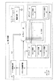
図1は本発明の実施形態による表示装置60の構成を示している。表示装置60は、m×n個のセルのアレイからなる表示面を有する3電極面放電型のPDP10と、セルのアレイを選択的に発光させるためのドライブユニット50とを具えており、例えばテレビジョン受像機、コンピュータ・システムのモニタ等に利用される。
FIG. 1 shows a configuration of a display device 60 according to an embodiment of the present invention. The display device 60 includes a three-electrode surface
PDP10では、表示放電を生じさせるための電極対を構成する表示電極XおよびYが平行に配置され、これら表示電極XおよびYと交差するようにアドレス電極Aが配置されている。表示電極Xはサステイン(維持)電極であり、表示電極Yはスキャン(走査)電極である。表示電極XおよびYは、典型的には画面の行方向または水平方向に延び、アドレス電極Aは列方向または垂直方向に延びている。
In the
ドライブユニット50は、ドライバ制御回路51、データ変換回路52、電源回路53、X電極ドライバ回路またはXドライバ回路61、Y電極ドライバ回路またはYドライバ回路64、およびアドレス電極ドライバ回路またはAドライバ回路68を含んでおり、場合によってROMを含み得る集積回路の形態で実装される。ドライブユニット50には、TVチューナまたはコンピュータのような外部装置からR,GおよびBの3原色の発光強度を示すフィールドデータDfが各種の同期信号とともに入力される。フィールドデータDfはデータ変換回路52の中のフィールドメモリに一時的に記憶される。データ変換回路52は、フィールドデータDfを階調表示のためのサブフィールドデータDsfに変換してAドライバ回路68に供給する。サブフィールドデータDsfは、1セル当たり1ビットの表示データの集合であって、その各ビットの値は該当する1つのサブフィールドSFにおける各セルの発光の要否、より正確にはアドレス放電の要否を表す。
The
Xドライバ回路61は、PDP表示面を構成する複数のセルの壁電圧を均等にするために表示電極Xに初期化のための電圧を印加するリセット回路62と、セルに表示放電を生じさせるために表示電極Xにサステインパルスを印加するサステイン回路63とを含んでいる。Yドライバ回路64は、表示電極Yに初期化のための電圧を印加するリセット回路65と、アドレッシングにおいて表示電極Yにスキャンパルスを印加するスキャン回路66と、セルに表示放電を生じさせるために表示電極Yにサステインパルスを印加するサステイン回路67とを含んでいる。Aドライバ回路68は、表示データに応じてサブフィールドデータDsfによって指定されたアドレス電極Aにアドレスパルスを印加する。
The
ドライバ制御回路51は、パルス電圧の印加およびサブフィールドデータDsfの転送を制御する。電源回路53はユニット内の所要部分に駆動電力を供給する。 The driver control circuit 51 controls the application of the pulse voltage and the transfer of the subfield data Dsf. The power supply circuit 53 supplies driving power to a required part in the unit.
図2はPDP10のセル構造の一例を示している。PDP10は1対の基板構体(ガラス基板上にセル構成要素を設けた構造体)100および20からなる。前面側のガラス基板11の内面に、n行m列の表示面ESの各行に1対ずつ表示電極XおよびYが配置されている。この図において、表示電極XおよびYの添字jは任意の行の位置を示し、アドレス電極Aの添字iは任意の列の位置を示す。表示電極XおよびYは、面放電ギャップを形成する透明導電膜41とその端縁部に重ねられた金属膜42とからなり、誘電体層17および保護膜18が被覆されている。背面側のガラス基板21の内面に1列に1本ずつアドレス電極Aが配列されており、これらアドレス電極Aは誘電体層24で被覆されている。誘電体層24の上に放電空間を列毎に区画する隔壁またはリブ29が設けられている。隔壁のパターンはストライプのパターンである。誘電体層24の表面および隔壁29の側面を被覆するカラー表示用の蛍光体層28R,28Gおよび28Bは、放電ガスが放つ紫外線によって局部的に励起されて発光する。図中の斜体文字(R,G,B)は蛍光体の発光色を示す。色配列は各列のセルを同色とするR,GおよびBの繰り返しパターンである。
FIG. 2 shows an example of the cell structure of the
1つのピクチャ(画面)は典型的には約16.7msの1フレーム期間で構成されており、インターレース型走査では1フレームが2つのフィールドで構成され、プログレッシブ型走査では1フレームが1つのフィールドで構成されている。PDP10による表示では、2値の発光制御によってカラー再現を行うために、典型的にはそのような1フィールド期間の入力画像の時系列の1つのフィールドFを所定数qのサブフィールドSFに分割する。典型的には、各フィールドFをq個のサブフィールドSFの集合に置き換える。しばしば、これらサブフィールドSFに順に20,21,22,...2q−1の重みを付けて各サブフィールドSFの表示放電の回数を設定する。但し、サブフィールドSFの重み付けは前記のような2の乗数に限定されるものではない。サブフィールド単位の発光/非発光の組合せでR,GおよびBの各色毎にN(=1+21+22+...+2q−1 )段階の輝度設定を行うことができる。このようなフィールド構成に合わせてフィールド転送周期であるフィールド期間Tfをq個のサブフィールド期間Tsfに分割し、各サブフィールドSFに1つのサブフィールド期間Tsfを割り当てる。さらに、サブフィールド期間Tsfを、初期化のためのリセット期間TR、アドレッシングのためのアドレス期間TA、および発光のための表示またはサステイン期間TSに分ける。典型的には、リセット期間TRおよびアドレス期間TAの長さが重みに係わらず一定であるのに対し、表示期間TSにおけるパルス数は重みが大きいほど多く、表示期間TSの長さは重みが大きいほど長い。この場合、サブフィールド期間Tsfの長さも、該当するサブフィールドSFの重みが大きいほど長い。但し、リセット期間TRおよびアドレス期間TAの長さは、それに限定されることなく、サブフィールド毎に異なっていてもよい。
One picture (screen) is typically composed of one frame period of about 16.7 ms. In interlaced scanning, one frame is composed of two fields, and in progressive scanning, one frame is composed of one field. It is configured. In the display by the
図3は、Xドライバ回路61、Yドライバ回路64およびAドライバ回路68の出力駆動電圧波形の概略的な通常の駆動シーケンスを例示している。なお、図示の波形は一例であり、振幅、極性およびタイミングを様々に変更することができる。
FIG. 3 illustrates a schematic normal drive sequence of output drive voltage waveforms of the
リセット期間TR、アドレス期間TAおよびサステイン期間TSの順序は、q個のサブフィールドSFにおいて同じであり、駆動シーケンスはサブフィールドSF毎に繰り返される。各サブフィールドSFのリセット期間TRにおいては、全ての表示電極Xに対して負極性のパルスPrx1と正極性のパルスPrx2とを順に印加し、全ての表示電極Yに対して正極性のパルスPry1と負極性のパルスPry2とを順に印加する。パルスPrx1,Pry1およびPry2は微小放電が生じる変化率で振幅が漸増するランプ波形(鈍波)パルスである。最初に印加されるパルスPrx1およびPry1は、前サブフィールドSFにおける発光/非発光に係わらず全てのセルに同一極性の適当な壁電圧を生じさせるために印加される。適度の壁電荷が存在するセルにパルスPrx2およびPry2を印加することにより、壁電圧を放電開始電圧とパルス振幅との差に相当する値に調整することができる。なお、表示電極XおよびYの片方にのみパルスを印加して初期化を行うことができるが、図示のように表示電極XおよびYの双方に互いに1対の逆極性のパルスを印加することによってドライバ回路素子の低耐圧化を図ることができる。セルに加わる駆動電圧は、表示電極XおよびYに印加されるパルスの振幅を加算した合成電圧である。 The order of the reset period TR, the address period TA, and the sustain period TS is the same in the q subfields SF, and the driving sequence is repeated for each subfield SF. In the reset period TR of each subfield SF, a negative pulse Prx1 and a positive pulse Prx2 are sequentially applied to all the display electrodes X, and a positive pulse Pry1 is applied to all the display electrodes Y. A negative pulse Pry2 is applied in order. The pulses Prx1, Pry1, and Pry2 are ramp waveform (blunt wave) pulses that gradually increase in amplitude at the rate of change at which microdischarge occurs. The first applied pulses Prx1 and Pry1 are applied to generate appropriate wall voltages of the same polarity in all cells regardless of light emission / non-light emission in the previous subfield SF. By applying the pulses Prx2 and Pry2 to a cell having an appropriate wall charge, the wall voltage can be adjusted to a value corresponding to the difference between the discharge start voltage and the pulse amplitude. Note that initialization can be performed by applying a pulse to only one of the display electrodes X and Y, but by applying a pair of opposite polarity pulses to both the display electrodes X and Y as shown in the figure. It is possible to reduce the breakdown voltage of the driver circuit element. The driving voltage applied to the cell is a combined voltage obtained by adding the amplitudes of the pulses applied to the display electrodes X and Y.
アドレス期間TAにおいては、発光させるセルのみに発光維持に必要な壁電荷を形成する。全ての表示電極Xおよび全ての表示電極Yを所定電位にバイアスした状態で、行選択期間(1行分のスキャン時間)毎に選択行に対応した1つの表示電極Yに負極性のスキャンパルス−Vyを印加する。この行選択と同時にアドレス放電を生じさせるべき選択セルに対応したアドレス電極AのみにアドレスパルスVaを印加する。つまり、選択行jのm列分のサブフィールドデータDsfに基づいてアドレス電極A1〜Amの電位を2値制御する。選択セルでは表示電極Yとアドレス電極Aとの間の放電が生じる。そのアドレス放電がトリガとなって、その後の表示電極X−Y間の面放電が生じる。これら一連の放電がアドレス放電である。 In the address period TA, wall charges necessary for maintaining light emission are formed only in the cells that emit light. With all display electrodes X and all display electrodes Y biased to a predetermined potential, a negative scan pulse is applied to one display electrode Y corresponding to the selected row every row selection period (scanning time for one row). Vy is applied. Simultaneously with this row selection, the address pulse Va is applied only to the address electrode A corresponding to the selected cell in which the address discharge is to be generated. That is, the potentials of the address electrodes A 1 to A m are binary-controlled based on the subfield data Dsf for m columns of the selected row j. In the selected cell, a discharge occurs between the display electrode Y and the address electrode A. The address discharge is a trigger, and subsequent surface discharge between the display electrodes XY occurs. These series of discharges are address discharges.
サステステイン期間TSにおいては、最初に全ての表示電極Yに対して所定極性(図の例では正極性)のサステインパルスPsを印加する。その後、表示電極Xと表示電極Yとに対して交互にサステインパルスPsを印加する。サステインパルスPsの振幅は維持電圧Vsである。サステインパルスPsの印加によって、所定の壁電荷が残存するセルにおいて面放電が生じる。サステインパルスPsの印加回数は、上述したようにサブフィールドSFの重みに対応する。なお、サステイン期間TS全体にわたって不要な対向放電を防止するために、アドレス電極AをサステインパルスPsと同極性の電圧Vasにバイアスする。 In the sustain period TS, a sustain pulse Ps having a predetermined polarity (positive polarity in the illustrated example) is first applied to all the display electrodes Y. Thereafter, the sustain pulse Ps is alternately applied to the display electrode X and the display electrode Y. The amplitude of the sustain pulse Ps is the sustain voltage Vs. By applying the sustain pulse Ps, a surface discharge is generated in a cell in which a predetermined wall charge remains. The number of times of application of the sustain pulse Ps corresponds to the weight of the subfield SF as described above. Note that the address electrode A is biased to the voltage Vas having the same polarity as the sustain pulse Ps in order to prevent unnecessary counter discharge throughout the sustain period TS.
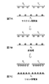
図4A、4Bおよび4Cは、図3の通常の駆動シーケンスによる、それぞれ、リセット放電後、その後のアドレス放電およびアドレス放電後における、セルのアドレス電極Ai、サステイン電極Xjおよびスキャン電極Yjにおける壁電荷の状態を示している。 4A, 4B, and 4C show the cell address electrode A i , the sustain electrode X j, and the scan electrode Y j after the reset discharge and the subsequent address discharge and address discharge, respectively, according to the normal driving sequence of FIG. The state of the wall charge is shown.
リセット期間TRではスキャン電極Yjのみを陽極とし、アドレス電極Aiとサステイン電極Xjを陰極とした関係が成立するように印加電圧波形や電位を制御している。その結果、図4Aに示されているように、リセット放電後のアドレス放電前では、Yj電極に負極性の電荷が、アドレス電極Aiとサステイン電極Xjには正極性の電荷がそれぞれ形成される。図4Bに示されているように、アドレス放電では、アドレス電極Aiとスキャン電極Yjの間の対向放電をトリガにして、サステイン電極Xjとスキャン電極Yjの間の面放電を引き起こさせる。図4Cに示されているように、アドレス放電終了後では、サステイン電極Xj上に負極性の電荷が、スキャン電極Yj上に正極性の電荷が形成され、サステイン放電が可能となる。 In the reset period TR, the applied voltage waveform and potential are controlled so that a relationship is established in which only the scan electrode Y j is the anode and the address electrode A i and the sustain electrode X j are the cathode. As a result, as shown in FIG. 4A, before the address discharge after the reset discharge, a negative charge is formed on the Y j electrode, and a positive charge is formed on the address electrode A i and the sustain electrode X j. Is done. As shown in FIG. 4B, in the address discharge, a counter discharge between the address electrode A i and the scan electrode Y j is used as a trigger to cause a surface discharge between the sustain electrode X j and the scan electrode Y j . . As shown in Figure 4C, the following address discharge ends, negative charges on the sustain electrode X j is a positive polarity charge is formed on the scan electrodes Y j, it is possible to sustain discharge.
しかし、3電極を含めたアドレス放電の形態なので、アドレス電極Aiとスキャン電極Yjの間の対向放電が発生してもスキャン電極Yjとサステイン電極Xjの間の面放電が発生しなければ、アドレス放電は失敗となる。従って、アドレスパルスの幅を所定値以上に大きくしなければならない。アドレスするのに時間がかかると、表示放電のための時間が短くなり、従って輝度および階調数が低下する。 However, since the address discharge includes three electrodes, even if the counter discharge between the address electrode A i and the scan electrode Y j occurs, the surface discharge between the scan electrode Y j and the sustain electrode X j must occur. In this case, the address discharge fails. Therefore, the width of the address pulse must be increased to a predetermined value or more. If it takes time to address, the time for display discharge is shortened, and therefore the luminance and the number of gradations are reduced.
本発明の実施形態によるPDPドライブユニット50は、リセット期間TRにおけるスキャン電極Yおよびサステイン電極Xに印加するパルス電圧またはランプ波電圧の極性に特徴を有する。それによってアドレス期間TAをより短くすることができ、それによって、サステイン期間TSをより長くでき、それによって表示品質をより高くすることができる。
The
図5A、5Bおよび5Cは、本発明の実施形態による、Aドライバ回路68、Xドライバ回路61およびYドライバ回路64の出力駆動電圧波形の概略的な駆動シーケンスを示している。なお、図示の波形は一例であり、波形、振幅、極性およびタイミングを様々に変更することができる。リセット期間TR、アドレス期間TAおよびサステイン期間TSの順序は、q個のサブフィールドSFにおいて同じであり、駆動シーケンスはサブフィールドSF毎に繰り返される。
5A, 5B, and 5C show schematic drive sequences of output drive voltage waveforms of the A driver circuit 68, the
本発明の実施形態によれば、各サブフィールドSFのリセット期間TRは、前処理期間RPRおよびリセット放電期間RDを含んでいる。アドレス期間TAは、アドレス放電期間ADおよび後処理期間APTを含んでいる。 According to the embodiment of the present invention, the reset period TR of each subfield SF includes a preprocessing period RPR and a reset discharge period RD. The address period TA includes an address discharge period AD and a post-processing period APT.
図6A、6Bおよび6Cは、それぞれ、前のサブフィールドSFのサステイン期間TSの終了後、その後のリセット期間TRの前処理期間RPR、およびリセット放電期間RD後における、点灯したセルのアドレス電極Ai、サステイン電極Xjおよびスキャン電極Yjにおける電荷の状態を示している。 6A, 6B and 6C respectively show the address electrodes A i of the lit cells after the end of the sustain period TS of the previous subfield SF, after the preprocessing period RPR of the subsequent reset period TR, and after the reset discharge period RD. , The state of charge in the sustain electrode X j and the scan electrode Y j is shown.
図7A、7Bおよび7Cは、それぞれ、前のサブフィールドSFのサステイン期間TSの終了後、その後のリセット期間TRの前処理期間RPR、およびリセット放電期間RD後における、点灯しなかったセルのアドレス電極Ai、サステイン電極Xjおよびスキャン電極Yjにおける電荷の状態を示している。 FIGS. 7A, 7B and 7C respectively show the address electrodes of the unlit cells after the end of the sustain period TS of the previous subfield SF, after the preprocessing period RPR of the subsequent reset period TR, and after the reset discharge period RD. The state of charge in A i , the sustain electrode X j and the scan electrode Y j is shown.
図6Aにおいて、サステイン期間TSの終了後の点灯したセルのアドレス電極Ai、サステイン電極Xjおよびスキャン電極Yjには、それぞれ正極性、負極性および正極性の電荷が形成されている。図7Aにおいて、サステイン期間TSの終了後の点灯しなかったセルのアドレス電極Ai、サステイン電極Xjおよびスキャン電極Yjには、それぞれ正極性、負極性および負極性の電荷が形成されているが、後で説明するように前のアドレス期間TAにおける消去放電によって壁電荷が既に消失している。 In FIG. 6A, positive, negative, and positive charges are respectively formed on the address electrode A i , the sustain electrode X j, and the scan electrode Y j of the lighted cell after the end of the sustain period TS. In FIG. 7A, positive, negative, and negative charges are respectively formed on the address electrode A i , the sustain electrode X j, and the scan electrode Y j of the cell that has not been lit after the end of the sustain period TS. However, as will be described later, the wall charges have already disappeared due to the erase discharge in the previous address period TA.
図5A〜5Cに示されているように、前処理期間RPRにおいて、Aドライバ回路68は、全てのアドレス電極A1〜Amに正極性パルス電圧Ppraを印加し、Xドライバ回路61のリセット回路62およびYドライバ回路64のリセット回路65は全てのサステイン電極X1〜Xnおよび全てのスキャン電極Y1〜Ynに負極性パルス電圧PprxおよびPpryを印加する。それによって、図6Bに示されているように、前のサスイテン期間TSにおいて点灯したセルについて、電極Aiと電極Xjの間で放電が生じ、電極Xj上の電荷の極性が反転する。それによって、電極Xjおよび電極Yj上の電荷の極性が同じ正極性になり、電荷量が概ね等しくなる。一方、図7Bにおいて、前処理期間RPRの後の非点灯セルのアドレス電極Ai、サステイン電極Xjおよびスキャン電極Yjは、壁電荷が消失しているので、放電が生じず、図7Aと同じ電荷の状態を維持する。セルの電極がこのような電荷の状態を取ることによって、後続のリセット放電期間RDにおいて、電極Xjと電極Aiの間と、電極Yjと電極Aiの間とにおける書き込み放電が促進される。
As shown in FIGS. 5A to 5C, in the preprocessing period RPR, the A driver circuit 68 applies the positive pulse voltage Ppra to all the address electrodes A1 to Am, and the
リセット放電期間RDにおいて、リセット回路62および65は、全てのサステイン電極Xに対してピーク値Vxwの正極性のランプ波または鈍波パルス電圧Prx1とピーク値−Vbxの負極性のランプ波パルス電圧Prx2とを順に印加し、全てのスキャン電極Yに対してピーク値Vywの正極性のランプ波パルス電圧Pry1とピーク値−Vbyの負極性のランプ波パルス電圧Pry2とを順に印加する。それによって、アドレス電極Aを陰極とする、スキャン電極Yとアドレス電極Aの間の放電と、サステイン電極Xとアドレス電極Aの間の放電とを生じさせる。ランプ波パルス電圧Prx1、Prx2、Pry1およびPry2は微小放電が生じるような変化率で振幅が変化するランプ波形パルス電圧である。最初に印加されるランプ波パルス電圧Prx1およびPry1は、前サブフィールドSFにおける点灯および非点灯に係わらず全てのセルに壁電圧を生じさせるために印加される。この期間において、アドレス電極Aは所定の電位、好ましくは接地電位GNDに維持される。適度の壁電荷が形成されたセルに後続のランプ波パルス電圧Prx2およびPry2を印加することによって、壁電圧を放電開始電圧とパルス振幅の間の差に相当する値に調整することができる。
In the reset discharge period RD, the
壁電圧を放電開始電圧とパルス振幅の間の差に相当する値に調整するため、次の不等式が成立するようなリセット・ランプ波パルスPrx1およびPry1のピーク電位VxwおよびVywを決定する。
|Vxw| > |Vfx-a| かつ
|Vyw| > |Vfy-a|
ここで、Vfx−aおよびVfy−aは、それぞれ、アドレス電極Aを陰極としたサステイン電極Xとアドレス電極Aの間の放電開始電圧、およびスキャン電極Yとアドレス電極Aの間の放電の開始電圧を表す。
In order to adjust the wall voltage to a value corresponding to the difference between the discharge start voltage and the pulse amplitude, the peak potentials Vxw and Vyw of the reset / ramp wave pulses Prx1 and Pry1 satisfying the following inequality are determined.
| Vxw |> | Vfx-a | And | Vyw |> | Vfy-a |
Here, Vfx-a and Vfy-a are the discharge start voltage between the sustain electrode X and the address electrode A, each having the address electrode A as a cathode, and the discharge start voltage between the scan electrode Y and the address electrode A, respectively. Represents.
このようにして、図6Cおよび7Cにおいて、リセット放電期間RDの後のそのセルのアドレス電極Ai、サステイン電極Xjおよびスキャン電極Yjには、それぞれ正極性、負極性および負極性の電荷が形成される。 In this manner, in FIGS. 6C and 7C, the positive electrode, the negative electrode, and the negative electrode are respectively charged in the address electrode A i , the sustain electrode X j and the scan electrode Y j of the cell after the reset discharge period RD. It is formed.
図8Aは、それぞれ、アドレス期間TAのアドレス放電期間AD中、アドレス放電期間ADの終了後、および後処理期間APTにおける点灯させるセルのアドレス電極Ai、サステイン電極Xjおよびスキャン電極Yjにおける電荷の状態を示している。 FIG. 8A shows the charge in the address electrode A i , the sustain electrode X j and the scan electrode Y j of the cells to be lit during the address discharge period AD of the address period TA, after the end of the address discharge period AD, and in the post-processing period APT, respectively. Shows the state.
図9Aは、それぞれ、アドレス期間TAのアドレス放電期間AD中、アドレス放電期間ADの終了後、および後処理期間APTにおける点灯させないセルのアドレス電極Ai、サステイン電極Xjおよびスキャン電極Yjにおける電荷の状態を示している。 FIG. 9A shows the charges in the address electrode A i , the sustain electrode X j, and the scan electrode Y j of the cells that are not lit during the address discharge period AD of the address period TA, after the end of the address discharge period AD, and in the post-processing period APT, respectively. Shows the state.
アドレス放電期間ADにおいては、点灯させるセルのみにおいて発光維持に必要な壁電荷を形成する。全てのサステイン電極Xおよび全てのスキャン電極Yを所定電位にバイアスした状態で、スキャン回路66は、行選択期間(1行分のスキャン時間)毎に選択行に対応した表示電極Yに負極性のスキャンパルス電圧−Vyを印加する。Xドライバ回路61およびYドライバ回路64は、非行選択期間中、サステイン電極Xおよびスキャン電極Yを同じ電位に(|Vxa|=|Vsc|)または異なる電位に(|Vxa|≠|Vsc|)バイアスしてもよい。Aドライバ回路68は、この行選択の期間にアドレス放電を生じさせるべき選択セルに対応したアドレス電極Aiにのみ正極性のアドレスパルス電圧Vaを印加する。他のアドレス電極Aは、リセット期間TRと同じ所定の電位、好ましくは接地電位GNDに維持される。即ち、選択行jのm列分のサブフィールドデータDsfに基づいてアドレス電極A1〜Amの電位を2値制御する。
In the address discharge period AD, wall charges necessary for maintaining light emission are formed only in the cells to be lit. In a state where all the sustain electrodes X and all the scan electrodes Y are biased to a predetermined potential, the scan circuit 66 applies a negative polarity to the display electrodes Y corresponding to the selected row every row selection period (scan time for one row). A scan pulse voltage -Vy is applied. The
アドレス放電をより発生させやすくするため、次の不等式が成立するようにランプ波パルスPry2の電位−Vbyおよびスキャンパルス電位−Vyを決定することが好ましい。
|Vby| < |Vy|
In order to make the address discharge easier to generate, it is preferable to determine the potential −Vby and the scan pulse potential −Vy of the ramp wave pulse Pry2 so that the following inequality is satisfied.
| Vby | <| Vy |
図8Aに示されているように、アドレス放電期間ADにおいて選択セルではスキャン電極Yjとアドレス電極Aiの間で放電が生じる。図8Bに示されているように、アドレス放電後、アドレス電極Aiには負極性の電荷が形成され、サステイン電極Xjには負極性の電荷が残留し、スキャン電極Yjには正極性の電荷が形成される。この場合、スキャン電極Xjとサステイン電極Yjの間で面放電は生じない。 As shown in Figure 8A, a discharge between the scan electrode Y j and the address electrode A i occurs at the selected cell during the address discharge period AD. As shown in FIG. 8B, after the address discharge, a negative charge is formed on the address electrode A i , a negative charge remains on the sustain electrode X j , and the scan electrode Y j has a positive charge. Are formed. In this case, no surface discharge occurs between the scan electrode Xj and the sustain electrode Yj .
一方、非選択セルでは放電が生じない。図9Aに示されているように、アドレス放電期間ADにおいて点灯セルの電極間には放電は生じず、アドレス電極Ai、サステイン電極Xjおよびスキャン電極Yjには、それぞれ正極性、負極性および負極性の電荷が維持され、図9Bに示されているように、アドレス放電期間RDの後も、そのセルの電極の電荷が維持される。 On the other hand, no discharge occurs in the non-selected cells. As shown in FIG. 9A, no discharge occurs between the electrodes of the lighted cells in the address discharge period AD, and the address electrode A i , the sustain electrode X j and the scan electrode Y j have a positive polarity and a negative polarity, respectively. The negative charge is maintained, and as shown in FIG. 9B, the charge of the electrode of the cell is maintained even after the address discharge period RD.
アドレス期間TAの後処理期間APTにおいて、非点灯セルにおける電荷を消去するための放電を生じさせる。この放電では、放電強度を小さく抑えたいので、Xドライバ回路61およびYドライバ回路64は、Xj電極およびYj電極にそれぞれピーク値−Vxeおよび−Vyeの負極性のランプ波パルス電圧PptxおよびPptyを印加することが好ましい。そのピーク値−Vxeおよび−Vyeはスキャンパルス電位−Vyと等しいことが好ましい。この期間において、Aドライバ回路68は、アドレス電極Aiに、好ましくはアドレスパルス電圧Vaと同じ高さの正極性パルス電圧Pptaを印加する。図9Cにおいて、後処理期間APTでは非点灯セルのサステイン電極Xjおよびスキャン電極Yjとアドレス電極Aiの間で小さな放電が生じ、図9Bにおけるそれぞれの電極の電荷が減少する。図8Cにおいては、サステイン電極Xjおよびスキャン電極Yjとアドレス電極Aiの間で放電は生じないが、後処理期間APTではアドレス放電した後の選択セルにおけるサステイン電極Xj上では、負の電荷が或る程度消失する。
In the post-processing period APT of the address period TA, a discharge for erasing the charge in the non-lighted cell is generated. In this discharge, we want to suppress the discharge intensity decreases,
サステイン期間TSの第1のサスイテンパルスS1の期間において、サステイン回路67は全てのスキャン電極Yに対して正極性のサステインパルス電圧Vsを幾分長い持続時間だけ印加し、サステイン回路63は、全てのサステイン電極Xに対して通常より大きい負極性の電圧−Vxsを幾分長い持続時間だけ印加して、後処理期間APTに選択セルの電極Xjで消失した壁電荷分の壁電圧を補償する。次いで、全てのサステイン電極Xに対して正極性のサステインパルス電圧Vsを幾分長い持続時間だけ印加する。その後のサステインパルスの期間S2、S3...において、サステイン回路67およびサステイン回路63は、表示電極Xおよび表示電極Yに対して交互により短い幅のサステインパルス電圧Vsを印加する。サステインパルス電圧Vsの印加によって、所定の壁電荷が残存する選択セルのサステイン電極Xjとスキャン電極Yjの間で面放電が生じる。サステインパルス電圧Vsの印加の回数は、上述したようにサブフィールドSFの重みに対応する。サステイン期間TS全体にわたって、アドレス電極Aは前述のリセット期間TRと同じ所定の電位、好ましくは接地電位に維持される。サステイン期間TSの後の点灯セルおよび非点灯セルのアドレス電極Ai、サステイン電極Xjおよびスキャン電極Yj上の電荷の状態は、前述のように図6Aおよび7Aに示されている。
In the period of the first sustain pulse S1 in the sustain period TS, the sustain
図6Aおよび6Bを再び参照すると、次のサブフィールドSFにおけるリセット期間TRの前処理期間RPRにおいて、前述のように、好ましくは全てのアドレス電極Aにアドレスパルス電位と同じ高さのパルス電圧を印加し、好ましくは全てのスキャン電極Yおよびサステイン電極Xにスキャンパルス電圧と同じ電位のパルス電圧を印加する。それによって、前のフィールドSFのサステイン期間TSにおいて点灯させたセルにおいてのみアドレス電極Aiとサステイン電極Xjの間の放電を生じさせ、サステイン電極Xj上の電荷の極性を反転させる。それによって、サステイン電極Xjおよびスキャン電極Yj上の電荷が同じ正極性になる。それによって、次のリセット放電期間RDにおいて、スキャン電極Yjとアドレス電極Aiの間と、サステイン電極Xjとアドレス電極Aiの間とにおける書き込み放電が生じやすくなる。一方、図7Aおよび7Bを参照すると、非選択セルは、前のアドレス期間TAの後処理期間APTにおける非選択セルの消去放電によって壁電荷を失っているので、放電は生じない。 Referring again to FIGS. 6A and 6B, in the preprocessing period RPR of the reset period TR in the next subfield SF, a pulse voltage having the same height as the address pulse potential is preferably applied to all the address electrodes A as described above. Preferably, a pulse voltage having the same potential as the scan pulse voltage is applied to all the scan electrodes Y and the sustain electrodes X. As a result, a discharge is generated between the address electrode A i and the sustain electrode X j only in the cells that are lit in the sustain period TS of the previous field SF, and the polarity of the charges on the sustain electrode X j is reversed. As a result, the charges on the sustain electrode X j and the scan electrode Y j have the same positive polarity. As a result, in the next reset discharge period RD, a write discharge is likely to occur between the scan electrode Y j and the address electrode A i and between the sustain electrode X j and the address electrode A i . On the other hand, referring to FIGS. 7A and 7B, the non-selected cell loses wall charges due to the erasing discharge of the non-selected cell in the post-processing period APT of the previous address period TA, and therefore no discharge occurs.
本発明の実施形態によれば、スキャン電極Yおよびサステイン電極Xに、正極性のランプ波電圧を印加して同じ極性の壁電荷を形成するので、アドレス期間のアドレス放電においてスキャン電極Xjとサステイン電極Yjの間で面放電を生じさせる必要がなく、従ってPDPにおける駆動のアドレス期間をより短くでき、それによって表示期間をより長くでき、それによってPDPにおいてより高い表示品質を実現することができる。 According to the embodiment of the present invention, since the positive polarity ramp wave voltage is applied to the scan electrode Y and the sustain electrode X to form wall charges having the same polarity, the scan electrode Xj and the sustain electrode are addressed during the address discharge in the address period. It is not necessary to cause a surface discharge between the electrodes Yj , and therefore, the driving address period in the PDP can be shortened, thereby making it possible to lengthen the display period, thereby realizing higher display quality in the PDP. .
以上説明した実施形態は典型例として挙げたに過ぎず、その各実施形態の構成要素を組み合わせること、その変形およびバリエーションは当業者にとって明らかであり、当業者であれば本発明の原理および請求の範囲に記載した発明の範囲を逸脱することなく上述の実施形態の種々の変形を行えることは明らかである。 The embodiments described above are merely given as typical examples, and it is obvious to those skilled in the art to combine the components of each embodiment, and variations and variations thereof will be apparent to those skilled in the art. It will be apparent that various modifications of the above-described embodiments can be made without departing from the scope of the invention as set forth in the scope.
60 表示装置
10 PDP
50 ドライブユニット
51 ドライバ制御回路
52 データ変換回路
53 電源回路
61 Xドライバ回路
62 リセット回路
63 サステイン回路
64 Yドライバ回路
65 リセット回路
66 スキャン回路
67 サステイン回路
60
50 drive unit 51 driver control circuit 52 data conversion circuit 53 power supply circuit 61
Claims (7)
表示対象セルをアドレスする際に、前記第2電極と前記第3電極の間でアドレス用放電を発生させる操作の前に、前記第1電極及び第2電極上の誘電体層に同一極性の壁電荷を形成する操作を行い、その後、前記第1電極および第2電極の電位を負電位にバイアスし、選択行に対応した前記第2電極に負極性のスキャンパルスを印加することにより、前記アドレス用放電を前記第2電極と前記第3電極の間でのみ発生させるようにしたことを特徴とする、プラズマディスプレイパネルの駆動方法。 A method for driving a plasma display panel, wherein each cell includes a parallel first electrode and a second electrode covered with a dielectric, and a third electrode provided in a direction intersecting the first electrode and the second electrode. Because
When addressing a display target cell, a wall having the same polarity is formed on the dielectric layer on the first electrode and the second electrode before an operation for generating an address discharge between the second electrode and the third electrode. There line operations for forming the charge, then the potential of the first electrode and the second electrode is biased to a negative potential by applying a negative scan pulse to the second electrode corresponding to the selected row, wherein A method for driving a plasma display panel, wherein an address discharge is generated only between the second electrode and the third electrode.
前記リセット期間に、全てのセルの前記第1電極及び第2電極上の誘電体層に同一極性の壁電荷を形成し、
前記アドレス期間に、前記第1電極および第2電極の電位を負電位にバイアスし、選択行に対応した前記第2電極に負極性のスキャンパルスを印加することにより、点灯セルの第2電極と第3電極の間でのみ放電を発生させることを特徴とする、プラズマディスプレイパネルの駆動方法。 Driving a plasma display panel provided in each cell with parallel first and second electrodes covered with a dielectric, and a third electrode provided in a direction intersecting the first and second electrodes In this case, the plasma is divided into a reset period for adjusting a plurality of wall charges, an address period for lighting an arbitrary cell according to display data, and a sustain period for maintaining lighting of the lit cell. A display panel driving method comprising:
During the reset period, wall charges of the same polarity are formed in the dielectric layers on the first electrode and the second electrode of all cells,
In the address period, by biasing the potential of the first electrode and the second electrode to a negative potential and applying a negative scan pulse to the second electrode corresponding to the selected row, A method for driving a plasma display panel, wherein discharge is generated only between third electrodes.
Priority Applications (5)
| Application Number | Priority Date | Filing Date | Title |
|---|---|---|---|
| JP2004223368A JP4577681B2 (en) | 2004-07-30 | 2004-07-30 | Driving method of plasma display panel |
| EP04257348A EP1622114A3 (en) | 2004-07-30 | 2004-11-26 | Method for driving a plasma display panel |
| US10/999,060 US7436375B2 (en) | 2004-07-30 | 2004-11-30 | Method for driving plasma display panel |
| KR1020040100578A KR100690482B1 (en) | 2004-07-30 | 2004-12-02 | Method for driving plasma display panel |
| CNB2005100018932A CN100489937C (en) | 2004-07-30 | 2005-01-24 | Method for driving plasma display panel |
Applications Claiming Priority (1)
| Application Number | Priority Date | Filing Date | Title |
|---|---|---|---|
| JP2004223368A JP4577681B2 (en) | 2004-07-30 | 2004-07-30 | Driving method of plasma display panel |
Publications (2)
| Publication Number | Publication Date |
|---|---|
| JP2006039479A JP2006039479A (en) | 2006-02-09 |
| JP4577681B2 true JP4577681B2 (en) | 2010-11-10 |
Family
ID=34930846
Family Applications (1)
| Application Number | Title | Priority Date | Filing Date |
|---|---|---|---|
| JP2004223368A Expired - Fee Related JP4577681B2 (en) | 2004-07-30 | 2004-07-30 | Driving method of plasma display panel |
Country Status (5)
| Country | Link |
|---|---|
| US (1) | US7436375B2 (en) |
| EP (1) | EP1622114A3 (en) |
| JP (1) | JP4577681B2 (en) |
| KR (1) | KR100690482B1 (en) |
| CN (1) | CN100489937C (en) |
Families Citing this family (8)
| Publication number | Priority date | Publication date | Assignee | Title |
|---|---|---|---|---|
| CA2484813A1 (en) * | 2003-10-17 | 2005-04-17 | Espeed, Inc. | Systems and methods for providing enhanced volume-weighted average price trading |
| KR100589314B1 (en) * | 2003-11-26 | 2006-06-14 | 삼성에스디아이 주식회사 | Driving method of plasma display panel and plasma display device |
| KR100598184B1 (en) * | 2004-04-09 | 2006-07-10 | 엘지전자 주식회사 | Driving Apparatus of Plasma Display Panel |
| TWI319558B (en) * | 2004-11-19 | 2010-01-11 | Lg Electronics Inc | Plasma display device and method for driving the same |
| KR100708691B1 (en) * | 2005-06-11 | 2007-04-17 | 삼성에스디아이 주식회사 | Method for driving plasma display panel and plasma display panel driven by the same method |
| US7642992B2 (en) * | 2005-07-05 | 2010-01-05 | Lg Electronics Inc. | Plasma display apparatus and driving method thereof |
| JP2008070442A (en) * | 2006-09-12 | 2008-03-27 | Pioneer Electronic Corp | Drive method of plasma display panel |
| EP1898440A3 (en) * | 2006-09-08 | 2009-05-06 | Pioneer Corporation | Plasma display panel and drive method thereof |
Citations (4)
| Publication number | Priority date | Publication date | Assignee | Title |
|---|---|---|---|---|
| JPH08212930A (en) * | 1995-02-09 | 1996-08-20 | Matsushita Electron Corp | Driving method of gas discharge type display device |
| JP2003330411A (en) * | 2002-05-03 | 2003-11-19 | Lg Electronics Inc | Method and device for driving plasma display panel |
| JP2004348140A (en) * | 2003-05-23 | 2004-12-09 | Lg Electronics Inc | Driving method and device for plasma display panel |
| JP2005292840A (en) * | 2004-04-02 | 2005-10-20 | Lg Electronics Inc | Plasma display apparatus and driving method for the same |
Family Cites Families (11)
| Publication number | Priority date | Publication date | Assignee | Title |
|---|---|---|---|---|
| JP2776309B2 (en) * | 1995-07-07 | 1998-07-16 | 日本電気株式会社 | Driving method of plasma display panel |
| JP3221341B2 (en) * | 1997-01-27 | 2001-10-22 | 富士通株式会社 | Driving method of plasma display panel, plasma display panel and display device |
| JP3573968B2 (en) * | 1997-07-15 | 2004-10-06 | 富士通株式会社 | Driving method and driving device for plasma display |
| JP3455141B2 (en) | 1999-06-29 | 2003-10-14 | 富士通株式会社 | Driving method of plasma display panel |
| KR100358697B1 (en) * | 1999-08-31 | 2002-10-30 | 엘지전자 주식회사 | Method of Driving Plasma Display Panel |
| JP2002287694A (en) * | 2001-03-26 | 2002-10-04 | Hitachi Ltd | Method for driving plasma display panel, driving circuit and picture display device |
| KR100607511B1 (en) * | 2001-08-17 | 2006-08-02 | 엘지전자 주식회사 | Method of driving plasma display panel |
| KR100458569B1 (en) * | 2002-02-15 | 2004-12-03 | 삼성에스디아이 주식회사 | A driving method of plasma display panel |
| KR100503605B1 (en) * | 2002-05-03 | 2005-07-26 | 엘지전자 주식회사 | Method of driving plasma display panel |
| KR100486911B1 (en) | 2002-05-31 | 2005-05-03 | 엘지전자 주식회사 | Method and apparatus for driving plasma display panel |
| KR100489279B1 (en) * | 2003-02-25 | 2005-05-17 | 엘지전자 주식회사 | Method and apparatus for driving plasma display panel |
-
2004
- 2004-07-30 JP JP2004223368A patent/JP4577681B2/en not_active Expired - Fee Related
- 2004-11-26 EP EP04257348A patent/EP1622114A3/en not_active Withdrawn
- 2004-11-30 US US10/999,060 patent/US7436375B2/en not_active Expired - Fee Related
- 2004-12-02 KR KR1020040100578A patent/KR100690482B1/en not_active IP Right Cessation
-
2005
- 2005-01-24 CN CNB2005100018932A patent/CN100489937C/en not_active Expired - Fee Related
Patent Citations (4)
| Publication number | Priority date | Publication date | Assignee | Title |
|---|---|---|---|---|
| JPH08212930A (en) * | 1995-02-09 | 1996-08-20 | Matsushita Electron Corp | Driving method of gas discharge type display device |
| JP2003330411A (en) * | 2002-05-03 | 2003-11-19 | Lg Electronics Inc | Method and device for driving plasma display panel |
| JP2004348140A (en) * | 2003-05-23 | 2004-12-09 | Lg Electronics Inc | Driving method and device for plasma display panel |
| JP2005292840A (en) * | 2004-04-02 | 2005-10-20 | Lg Electronics Inc | Plasma display apparatus and driving method for the same |
Also Published As
| Publication number | Publication date |
|---|---|
| CN100489937C (en) | 2009-05-20 |
| CN1728211A (en) | 2006-02-01 |
| EP1622114A3 (en) | 2009-02-25 |
| US20060022967A1 (en) | 2006-02-02 |
| EP1622114A2 (en) | 2006-02-01 |
| US7436375B2 (en) | 2008-10-14 |
| JP2006039479A (en) | 2006-02-09 |
| KR100690482B1 (en) | 2007-03-09 |
| KR20060011773A (en) | 2006-02-03 |
Similar Documents
| Publication | Publication Date | Title |
|---|---|---|
| KR100809406B1 (en) | Method of driving plasma display panel and display device | |
| JP3511495B2 (en) | Driving method and driving device for AC PDP | |
| US6054970A (en) | Method for driving an ac-driven PDP | |
| JP4162434B2 (en) | Driving method of plasma display panel | |
| JP4158875B2 (en) | Driving method and driving apparatus for AC type PDP | |
| JP2002215085A (en) | Plasma display panel and driving method therefor | |
| KR100678547B1 (en) | Method for driving plasma display panel | |
| KR100691682B1 (en) | Driving method of plasma display panel and display unit | |
| JP4415217B2 (en) | Driving method of plasma display panel | |
| JP5152183B2 (en) | Plasma display device and driving method thereof | |
| JP4089759B2 (en) | Driving method of AC type PDP | |
| JP4577681B2 (en) | Driving method of plasma display panel | |
| KR20010085248A (en) | Adjusting method of applied voltage in plasma display panel and driving method thereof | |
| KR100961185B1 (en) | Driving method of plasma display panel | |
| JP4646020B2 (en) | Driving method of plasma display panel | |
| JP2007133291A (en) | Driving method of plasma display panel | |
| KR100813336B1 (en) | Plasma display device and driving method thereof | |
| JP2007041249A (en) | Driving method of plasma display panel | |
| JP2004085693A (en) | Method of driving plasma display panel and plasma display | |
| JP2010008583A (en) | Method of driving plasma display panel | |
| JP2007041250A (en) | Driving method of plasma display panel | |
| WO2006008798A1 (en) | Display driving method | |
| JPWO2008018125A1 (en) | Plasma display panel driving method and plasma display apparatus | |
| JP2008281692A (en) | Method for driving plasma display panel |
Legal Events
| Date | Code | Title | Description |
|---|---|---|---|
| A521 | Written amendment |
Free format text: JAPANESE INTERMEDIATE CODE: A523 Effective date: 20051206 |
|
| RD04 | Notification of resignation of power of attorney |
Free format text: JAPANESE INTERMEDIATE CODE: A7424 Effective date: 20051207 |
|
| A621 | Written request for application examination |
Free format text: JAPANESE INTERMEDIATE CODE: A621 Effective date: 20070611 |
|
| A977 | Report on retrieval |
Free format text: JAPANESE INTERMEDIATE CODE: A971007 Effective date: 20091102 |
|
| A131 | Notification of reasons for refusal |
Free format text: JAPANESE INTERMEDIATE CODE: A131 Effective date: 20100209 |
|
| A521 | Written amendment |
Free format text: JAPANESE INTERMEDIATE CODE: A523 Effective date: 20100412 |
|
| TRDD | Decision of grant or rejection written | ||
| A01 | Written decision to grant a patent or to grant a registration (utility model) |
Free format text: JAPANESE INTERMEDIATE CODE: A01 Effective date: 20100817 |
|
| A01 | Written decision to grant a patent or to grant a registration (utility model) |
Free format text: JAPANESE INTERMEDIATE CODE: A01 |
|
| A61 | First payment of annual fees (during grant procedure) |
Free format text: JAPANESE INTERMEDIATE CODE: A61 Effective date: 20100817 |
|
| R150 | Certificate of patent or registration of utility model |
Free format text: JAPANESE INTERMEDIATE CODE: R150 |
|
| R154 | Certificate of patent or utility model (reissue) |
Free format text: JAPANESE INTERMEDIATE CODE: R154 |
|
| FPAY | Renewal fee payment (event date is renewal date of database) |
Free format text: PAYMENT UNTIL: 20130903 Year of fee payment: 3 |
|
| S131 | Request for trust registration of transfer of right |
Free format text: JAPANESE INTERMEDIATE CODE: R313135 |
|
| SZ03 | Written request for cancellation of trust registration |
Free format text: JAPANESE INTERMEDIATE CODE: R313Z03 |
|
| R350 | Written notification of registration of transfer |
Free format text: JAPANESE INTERMEDIATE CODE: R350 |
|
| S111 | Request for change of ownership or part of ownership |
Free format text: JAPANESE INTERMEDIATE CODE: R313113 |
|
| FPAY | Renewal fee payment (event date is renewal date of database) |
Free format text: PAYMENT UNTIL: 20130903 Year of fee payment: 3 |
|
| S111 | Request for change of ownership or part of ownership |
Free format text: JAPANESE INTERMEDIATE CODE: R313111 |
|
| R350 | Written notification of registration of transfer |
Free format text: JAPANESE INTERMEDIATE CODE: R350 |
|
| LAPS | Cancellation because of no payment of annual fees |