JP4577427B2 - DISC RECORDING MEDIUM, DISC DRIVE DEVICE, REPRODUCTION METHOD, AND DISC MANUFACTURING METHOD - Google Patents
DISC RECORDING MEDIUM, DISC DRIVE DEVICE, REPRODUCTION METHOD, AND DISC MANUFACTURING METHOD Download PDFInfo
- Publication number
- JP4577427B2 JP4577427B2 JP2008193917A JP2008193917A JP4577427B2 JP 4577427 B2 JP4577427 B2 JP 4577427B2 JP 2008193917 A JP2008193917 A JP 2008193917A JP 2008193917 A JP2008193917 A JP 2008193917A JP 4577427 B2 JP4577427 B2 JP 4577427B2
- Authority
- JP
- Japan
- Prior art keywords
- information
- frame
- recording
- wobbling
- recorded
- Prior art date
- Legal status (The legal status is an assumption and is not a legal conclusion. Google has not performed a legal analysis and makes no representation as to the accuracy of the status listed.)
- Expired - Lifetime
Links
Images


Description
本発明は、光ディスク等のディスク記録媒体、およびそのディスク記録媒体の製造のためのディスク製造方法、さらにはディスク記録媒体に対するディスクドライブ装置、再生方法に関し、特に、プリグルーブとしてトラックがウォブリングされたディスクに関するものである。 The present invention relates to a disk recording medium such as an optical disk, a disk manufacturing method for manufacturing the disk recording medium, a disk drive device for the disk recording medium, and a playback method, and in particular, a disk with tracks wobbled as a pregroove. It is about.
デジタルデータを記録・再生するための技術として、例えば、CD(Compact Disk),MD(Mini-Disk),DVD(Digital Versatile Disk)などの、光ディスク(光磁気ディスクを含む)を記録メディアに用いたデータ記録技術がある。光ディスクとは、金属薄板をプラスチックで保護した円盤に、レーザ光を照射し、その反射光の変化で信号を読み取る記録メディアの総称である。
光ディスクには、例えばCD、CD−ROM、DVD−ROMなどとして知られているように再生専用タイプのものと、MD、CD−R、CD−RW、DVD−R、DVD−RW、DVD+RW、DVD−RAMなどで知られているようにユーザーデータが記録可能なタイプがある。記録可能タイプのものは、光磁気記録方式、相変化記録方式、色素膜変化記録方式などが利用されることで、データが記録可能とされる。色素膜変化記録方式はライトワンス記録方式とも呼ばれ、一度だけデータ記録が可能で書換不能であるため、データ保存用途などに好適とされる。一方、光磁気記録方式や相変化記録方式は、データの書換が可能であり音楽、映像、ゲーム、アプリケーションプログラム等の各種コンテンツデータの記録を始めとして各種用途に利用される。
As a technique for recording / reproducing digital data, optical disks (including magneto-optical disks) such as CD (Compact Disk), MD (Mini-Disk), and DVD (Digital Versatile Disk) are used as recording media. There is data recording technology. An optical disk is a generic term for recording media that irradiate laser light onto a disk in which a thin metal plate is protected with plastic, and read signals by changes in reflected light.
The optical disc includes, for example, a read-only type as known as CD, CD-ROM, DVD-ROM, MD, CD-R, CD-RW, DVD-R, DVD-RW, DVD + RW, DVD -There is a type in which user data can be recorded as known in RAM and the like. In the recordable type, data can be recorded by using a magneto-optical recording method, a phase change recording method, a dye film change recording method, or the like. The dye film change recording method is also called a write-once recording method, and can be recorded only once and cannot be rewritten. On the other hand, the magneto-optical recording method and the phase change recording method can rewrite data and are used for various purposes such as recording of various content data such as music, video, games, application programs and the like.
光磁気記録方式、色素膜変化記録方式、相変化記録方式などの記録可能なディスクに対してデータを記録するには、データトラックに対するトラッキングを行うための案内手段が必要になり、このために、プリグルーブとして予め溝(グルーブ)を形成し、そのグルーブもしくはランド(グルーブとグルーブに挟まれる断面台地状の部位)をデータトラックとすることが行われている。
またデータトラック上の所定の位置にデータを記録することができるようにアドレス情報を記録する必要もあるが、このアドレス情報は、グルーブをウォブリング(蛇行)させることで記録される場合がある。
In order to record data on a recordable disc such as a magneto-optical recording method, a dye film change recording method, a phase change recording method, etc., a guide means for tracking the data track is required. Grooves (grooves) are formed in advance as pregrooves, and the grooves or lands (cross-section plateau-like portions sandwiched between the grooves and the grooves) are used as data tracks.
Further, it is necessary to record address information so that data can be recorded at a predetermined position on the data track, but this address information may be recorded by wobbling (meandering) the groove.
すなわち、データを記録するトラックが例えばプリグループとして予め形成されるが、このプリグループの側壁をアドレス情報に対応してウォブリングさせる。
このようにすると、記録時や再生時に、反射光情報として得られるウォブリング情報からアドレスを読み取ることができ、例えばアドレスを示すピットデータ等を予めトラック上に形成しておかなくても、所望の位置にデータを記録再生することができる。
このようにウォブリンググルーブとしてアドレス情報を付加することで、例えばトラック上に離散的にアドレスエリアを設けて例えばピットデータとしてアドレスを記録することが不要となり、そのアドレスエリアが不要となる分、実データの記録容量を増大させることができる。
なお、このようなウォブリングされたグルーブにより表現される絶対時間(アドレス)情報は、ATIP(Absolute Time In Pregroove)又はADIP(Adress In Pregroove)と呼ばれる。
That is, a track for recording data is formed in advance as a pregroup, for example, and the side wall of the pregroup is wobbled in correspondence with the address information.
In this way, the address can be read from the wobbling information obtained as reflected light information at the time of recording or reproduction. For example, even if pit data indicating the address is not formed on the track in advance, the desired position can be read. Data can be recorded and reproduced.
By adding address information as a wobbling groove in this way, for example, it becomes unnecessary to provide an address area discretely on a track and record an address as, for example, pit data. Recording capacity can be increased.
The absolute time (address) information expressed by such a wobbling groove is called ATIP (Absolute Time In Pregroove) or ADIP (Adress In Pregroove).
ところで近年、アドレス情報やユーザーが記録再生する情報以外に、アドレス情報と同様、あらかじめ、ディスク上に、各種の情報を記録することが必要になってきた。
即ち予めディスクに記録されるプリレコーデッド情報として、ディスクへの記録条件、例えば記録線速度やレーザパワー推奨値などを示すディスク情報や、ハックされた機器を排除するためなどのコピープロテクト情報を記録したい。とりわけコピープロテクト用の情報は重要とされている。
In recent years, in addition to address information and information recorded and reproduced by users, it has become necessary to record various types of information on a disk in advance, as with address information.
That is, as pre-recorded information recorded on the disc in advance, disc information indicating the recording conditions on the disc, for example, recording linear velocity and recommended laser power, and copy protection information for eliminating hacked devices are recorded. Want to. In particular, copy protection information is important.
各種情報をディスクにプリレコードする方法としては、エンボスピットをディスク上に形成することが知られている。
ところが光ディスクに高密度に記録再生することを考えると、エンボスピットによるプリレコード方法は不都合が生ずる。
As a method for pre-recording various information on a disc, it is known to form embossed pits on the disc.
However, in consideration of recording / reproducing with high density on an optical disc, the prerecording method using embossed pits is inconvenient.
光ディスクに高密度に記録再生する場合、グルーブの深さを浅くすることが必要とされている。そしてスタンパによってグルーブとエンボスピットを同時に生産するディスクにおいては、グルーブとエンボスピットの深さを異なる深さとすることは非常に困難である。このため、エンボスピットの深さはグルーブの深さと同じにならざるを得ない。
ところが、エンボスピットの深さが浅くなると、エンボスピットから品質のよい信号が得られないという問題がある。
In the case of recording / reproducing with high density on an optical disc, it is necessary to reduce the depth of the groove. In a disc in which grooves and embossed pits are produced simultaneously by a stamper, it is very difficult to make the depths of the grooves and embossed pits different. For this reason, the depth of the embossed pits must be the same as the depth of the grooves.
However, when the depth of the embossed pit becomes shallow, there is a problem that a signal with good quality cannot be obtained from the embossed pit.
例えば、光学系として405nmの波長のレーザダイオードと、NA=0.85の対物レンズを用い、カバー(サブストレート)厚み0.1mmのディスク上に、トラックピッチ0.32μm、線密度0.12μm/bitにて、フェーズチェンジマーク(相変化マーク)を記録再生することで、直径12cmの光ディスクに23GB(ギガバイト)の容量を記録再生することができる。
この場合、フェーズチェンジマークは、ディスク上にスパイラル状に形成されたグルーブ上に記録再生されるが、高密度化のためにメディアノイズをおさえるためには、グルーブの深さは、約20nm、つまり波長λに対してλ/13〜λ/12がのぞましい。
一方、品質のよいエンボスピットからの信号を得るには、エンボスピットの深さは、λ/8〜λ/4がのぞましく、結局グルーブ及びエンボスピットとしての共通の深さとして、いい解が得られないでいた。
このような事情から、エンボスピットにかわる、情報をプリレコードする方法が求められていた。
For example, a laser diode with a wavelength of 405 nm and an objective lens with NA = 0.85 are used as an optical system, and a track pitch is 0.32 μm and a linear density is 0.12 μm / bit on a disk with a cover (substrate) thickness of 0.1 mm. By recording and reproducing the phase change mark (phase change mark), it is possible to record and reproduce a capacity of 23 GB (gigabytes) on an optical disk having a diameter of 12 cm.
In this case, the phase change mark is recorded / reproduced on a groove formed in a spiral shape on the disc. However, in order to suppress media noise for higher density, the groove depth is about 20 nm, that is, Λ / 13 to λ / 12 is preferable for the wavelength λ.
On the other hand, in order to obtain a good quality embossed pit signal, the depth of the embossed pit is preferably λ / 8 to λ / 4. Was not obtained.
Under these circumstances, a method for pre-recording information instead of embossed pits has been demanded.
本発明はこれらの事情に鑑みて、ディスク記録媒体としての大容量化や記録再生性能の向上に好適なプリレコード方式を用いる新規な光記録媒体、及びそれを製造するためのディスク製造方法、及びディスクドライブ装置。再生方法を提供することを目的とする。 In view of these circumstances, the present invention provides a novel optical recording medium using a prerecording method suitable for increasing the capacity and improving the recording / reproducing performance as a disk recording medium, and a disk manufacturing method for manufacturing the same, and Disk drive device. An object is to provide a reproduction method.
このために本発明のディスク記録媒体は、ディスク上にトラックを形成するためのグルーブがスパイラル状に形成されており、上記グルーブのウォブリングによってアドレス情報が記録されると共に、当該グルーブによって形成されるトラックが記録マーク情報の記録再生に用いられる記録再生領域と、上記グルーブのウォブリングによってプリレコーデッド情報が記録される再生専用領域と、を有し、上記プリレコーデッド情報のECCブロックは第1の数のフレーム単位に分割され、上記再生専用領域のフレームシンクとして、上記第1の数よりも少ない第2の数の種類のフレームシンクを用い、上記第1の数のフレームに、上記フレームシンクの種類を、決められた順番に配置されものである。
For this purpose, the disk recording medium of the present invention has a groove for forming a track on the disk formed in a spiral shape, and address information is recorded by wobbling the groove, and the track formed by the groove. Has a recording / reproducing area used for recording / reproducing the recording mark information and a reproduction-only area in which pre-recorded information is recorded by the wobbling of the groove, and the ECC block of the pre-recorded information has the first number. As the frame sync of the read-only area, a second number of types of frame syncs smaller than the first number are used as frame syncs of the playback-only area, and the type of the frame sync is used for the first number of frames. Are arranged in a predetermined order .
本発明のディスクドライブ装置は、ディスク上にトラックを形成するためのグルーブがスパイラル状に形成されており、上記グルーブのウォブリングによってアドレス情報が記録されると共に、当該グルーブによって形成されるトラックが記録マーク情報の記録再生に用いられる記録再生領域と、上記グルーブのウォブリングによってプリレコーデッド情報が記録される再生専用領域と、を有し、上記プリレコーデッド情報のECCブロックは第1の数のフレーム単位に分割され、上記再生専用領域のフレームシンクとして、上記第1の数よりも少ない第2の数の種類のフレームシンクを用い、上記第1の数のフレームに、上記フレームシンクの種類を、決められた順番に配置されたディスク記録媒体に対して、データの記録又は再生を行うディスクドライブ装置であって、上記トラックに対してレーザ照射を行い反射光信号を得るヘッド手段と、上記反射光信号からトラックのウォブリングに係る信号を抽出するウォブリング抽出手段と、上記反射光信号から相変化マーク情報に係る信号を抽出する相変化マーク情報抽出手段と、上記記録再生領域の再生時において、上記ウォブリング抽出手段によって抽出された上記ウォブリングに係る信号についてMSK復調を行い、上記アドレス情報をデコードするアドレスデコード手段と、上記記録再生領域の再生時において、上記相変化マーク情報抽出手段によって抽出された上記相変化マーク情報に係る信号についてデコード処理を行い、相変化マーク情報として記録された情報を得る相変化マークデコード手段と、上記再生専用領域の再生時において、上記ウォブリング抽出手段によって抽出された上記ウォブリングに係る信号についてデコードを行い、上記プリレコーデッド情報を得るプリレコーデッド情報デコード手段と、を備える。
In the disk drive device of the present invention, a groove for forming a track on the disk is formed in a spiral shape, address information is recorded by wobbling the groove, and a track formed by the groove is a recording mark. A recording / reproducing area used for recording / reproducing information, and a reproduction-only area in which pre-recorded information is recorded by wobbling of the groove, and the ECC block of the pre-recorded information has a first number of frame units As the frame sync of the reproduction-only area, a second number of types of frame syncs smaller than the first number are used, and the type of the frame sync is determined for the first number of frames. against was sequentially disposed a disk recording medium, for recording or reproducing data A disk drive device comprising: head means for irradiating the track with laser to obtain a reflected light signal; wobbling extracting means for extracting a signal related to wobbling of the track from the reflected light signal; and a phase from the reflected light signal. Phase change mark information extracting means for extracting a signal related to change mark information, and MSK demodulation of the wobbling related signal extracted by the wobbling extracting means during decoding of the recording / reproducing area, and decoding the address information And decoding the signal related to the phase change mark information extracted by the phase change mark information extraction means during reproduction of the recording / reproduction area, and information recorded as phase change mark information Phase change mark decoding means to obtain During playback, it decodes the signal according to the wobbling extracted by said wobbling extracting means, and a pre-recorded information decoding means for obtaining the prerecorded information.
本発明の再生方法は、ディスク上にトラックを形成するためのグルーブがスパイラル状に形成されており、上記グルーブのウォブリングによってアドレス情報が記録されると共に、当該グルーブによって形成されるトラックが記録マーク情報の記録再生に用いられる記録再生領域と、上記グルーブのウォブリングによってプリレコーデッド情報が記録される再生専用領域と、を有し、上記プリレコーデッド情報のECCブロックは第1の数のフレーム単位に分割され、上記再生専用領域のフレームシンクとして、上記第1の数よりも少ない第2の数の種類のフレームシンクを用い、上記第1の数のフレームに、上記フレームシンクの種類を、決められた順番に配置されたディスク記録媒体に対する再生方法として、上記記録再生領域の再生時には、トラックに対してレーザ照射を行った際の反射光信号から、トラックのウォブリングに係る信号、及び相変化マーク情報に係る信号を抽出し、抽出された上記ウォブリングに係る信号についてMSK復調を行って上記アドレス情報をデコードするとともに、抽出された上記相変化マーク情報に係る信号についてデコード処理を行って相変化マーク情報として記録された情報を得、上記再生専用領域の再生時には、トラックに対してレーザ照射を行った際の反射光信号から、トラックのウォブリングに係る信号を抽出し、抽出された上記ウォブリングに係る信号についてデコードを行い、上記プリレコーデッド情報を得ることを特徴とする。
In the reproducing method of the present invention, a groove for forming a track on a disk is formed in a spiral shape, address information is recorded by wobbling the groove, and a track formed by the groove is recorded mark information. A recording / playback area used for recording / playback and a read-only area in which prerecorded information is recorded by wobbling the groove, and the ECC block of the prerecorded information is in a first number of frames. A second number of types of frame syncs smaller than the first number are used as frame syncs of the divided playback-only area, and the type of the frame sync can be determined for the first number of frames. and as a reproducing method for the placed disc recording medium in order, during reproduction of the recording and reproduction area Extracts the signal related to the wobbling of the track and the signal related to the phase change mark information from the reflected light signal when the laser is irradiated to the track, and performs the MSK demodulation on the extracted signal related to the wobbling In addition to decoding the address information, the signal related to the extracted phase change mark information is decoded to obtain information recorded as phase change mark information. A signal related to wobbling of a track is extracted from a reflected light signal at the time of laser irradiation, and the extracted signal related to wobbling is decoded to obtain the prerecorded information.
本発明のディスク製造方法は、ディスク上にトラックを形成するためのグルーブをスパイラル状に形成するとともに、再生専用領域のグルーブをプリレコーデッド情報に基づいてウォブリングさせたグルーブとして形成し、記録再生領域のグルーブを、アドレス情報に基づいてウォブリングさせたグルーブとして形成していくことで、当該グルーブによって形成されるトラックが記録マーク情報の記録再生に用いられるように形成し、上記プリレコーデッド情報のウォブリングは、第1の数のフレーム単位に分割され、上記再生専用領域のフレームシンクとして、上記第1の数よりも少ない第2の数の種類のフレームシンクを用い、上記第1の数のフレームに、上記フレームシンクの種類を、決められた順番に配置するようにしている。
In the disc manufacturing method of the present invention, a groove for forming a track on a disc is formed in a spiral shape, and a groove in a read-only area is formed as a groove wobbled based on prerecorded information, and a recording / playback area Is formed as a groove wobbled based on address information, so that a track formed by the groove is used for recording / reproduction of recording mark information, and the wobbling of the pre-recorded information is performed. Is divided into a first number of frames, and a second number of types of frame syncs smaller than the first number are used as frame syncs of the read-only area, and the first number of frames is The frame sync types are arranged in a predetermined order .
これらの本発明の要点は、即ち次のようになる。
トラッキングを行うトラックを形成するためにディスク上にスパイラル状に形成されたグルーブをウォブリングすることによって、記録再生領域と再生専用領域を形成する。
記録再生領域は、グルーブのウォブリングによりアドレス情報を記録し、アドレス情報を記録したグルーブによって形成されるトラックに、フェーズチェンジマークにより情報を記録再生する領域とする。
再生専用領域は、グルーブのウォブリングによってプリレコーデッド情報を記録した領域とする。またこの再生専用領域はフェーズチェンジマークによる情報を記録しない領域とする。
The main points of the present invention are as follows.
A recording / reproduction area and a reproduction-only area are formed by wobbling a spiral groove formed on the disk to form a track for tracking.
The recording / reproducing area is an area in which address information is recorded by groove wobbling, and information is recorded / reproduced by a phase change mark on a track formed by the groove in which the address information is recorded.
The reproduction-only area is an area where prerecorded information is recorded by groove wobbling. This reproduction-only area is an area in which information by the phase change mark is not recorded.
上記第2の数の種類のフレームシンクは、7種類のフレームシンクFS0、FS1、FS2、FS3、FS4、FS5、FS6であり、上記第1の数のフレームの最初のフレームには上記FS0を配置され、上記最初のフレーム以外のフレームには上記FS1、FS2、FS3、FS4、FS5、FS6のいずれかが配置されている。The second number of types of frame syncs are seven types of frame syncs FS0, FS1, FS2, FS3, FS4, FS5, and FS6. The first frame of the first number of frames is arranged with FS0. Any one of the FS1, FS2, FS3, FS4, FS5, and FS6 is arranged in a frame other than the first frame.
以上の説明から理解されるように本発明よれば以下のような効果が得られる。
即ち本発明のディスク記録媒体は、トラッキングを行うトラックを形成するためにディスク上にスパイラル状に形成されたグルーブをウォブリングすることによって、記録再生領域と再生専用領域を形成する。そして記録再生領域は、グルーブのウォブリングによりアドレス情報を記録し、アドレス情報を記録したグルーブによって形成されるトラックに、フェーズチェンジマークにより情報を記録再生する領域とし、また再生専用領域は、グルーブのウォブリングによってプリレコーデッド情報を記録した領域としている。
このため、エンボスピットによりプリレコーデッド情報を記録する必要が無くなる。そしてエンボスピットを形成する必要がないため、グルーブの深さを浅くすることができる。つまりエンボスピットの再生特性を考慮せずに、グルーブの深さを高密度記録にとって最適な状態に設定できる。従って、例えば直径12cmのディスクに23GBなどの容量を実現するような高密度記録が可能となる。
またディスクドライブ装置側では、プリレコーデッド情報をアドレス情報(ADIP)と同じウォブルチャンネルの再生系で再生(ウォブル情報の抽出)することができる。
As will be understood from the above description, the present invention provides the following effects.
That is, the disk recording medium of the present invention forms a recording / reproducing area and a reproduction-only area by wobbling a spiral groove formed on the disk to form a track for tracking. The recording / playback area records address information by groove wobbling, and records / reproduces information by phase change marks on the track formed by the groove in which the address information is recorded. The playback-only area is groove wobbling. The prerecorded information is recorded in the area.
This eliminates the need to record prerecorded information by embossed pits. And since it is not necessary to form an emboss pit, the depth of a groove can be made shallow. That is, the groove depth can be set to an optimum state for high-density recording without considering the reproduction characteristics of the emboss pits. Therefore, for example, high density recording that realizes a capacity of 23 GB or the like on a disk having a diameter of 12 cm is possible.
On the disk drive device side, pre-recorded information can be reproduced (extracted from wobble information) in the reproduction system of the same wobble channel as the address information (ADIP).
またエンボスピットを形成せずにウォブリンググルーブによるプリレコーデッド情報としてコピープロテクト情報を記録することで、ビデオ信号、オーディオ信号等の記録再生システムに適したストレージシステムを構築することができる。 Further, by recording copy protection information as pre-recorded information by a wobbling groove without forming embossed pits, a storage system suitable for a recording / playback system for video signals, audio signals, etc. can be constructed.
また再生専用領域はフェーズチェンジマークによる情報を記録しない領域としている。フェイズチェンジマークは、高反射率の記録層を低反射率に変換するマークといえるものであるため、フェイズチェンジマークが記録されたトラックは平均的に反射率は下がる。つまり戻り光が少なくなるが、これはグルーブのウォブリング成分の抽出にとってはSNR(Signal Noise Ratio)の点で不利となる。本発明では再生専用領域においてフェイズチェンジマークが記録されないことは、プリレコーデッド情報のSNRの劣化を防ぐことができ、品質のよいウォブリング信号を得ることができるものである。 In addition, the reproduction-only area is an area where information by the phase change mark is not recorded. Since the phase change mark can be said to be a mark for converting a recording layer having a high reflectivity to a low reflectivity, the track on which the phase change mark is recorded has an average lower reflectivity. That is, although the return light is reduced, this is disadvantageous in terms of SNR (Signal Noise Ratio) for extracting the wobbling component of the groove. In the present invention, the fact that the phase change mark is not recorded in the read-only area can prevent the SNR of the pre-recorded information from deteriorating and can obtain a high-quality wobbling signal.
また再生専用領域のプリレコーデッド情報を記録する線密度は、記録再生領域のフェーズチェンジマークによる情報の線密度より小さくし、かつアドレス情報の線密度より大きくしている。
プリレコーデッド情報の記録線密度を、フェイズチェンジマークの記録線密度より小さくすることによって、フェイズチェンジマークよりSNRの劣る、プシュプル信号より得られるウォブリング信号を品質よく再生することができる。
またプリレコーデッド情報の記録線密度を、アドレス情報(ADIP)の線密度より大きくすることによって、転送レートを高くすることができ、再生時間を短くすることができる。
The linear density for recording prerecorded information in the read-only area is smaller than the information linear density by the phase change mark in the recording / reproducing area and larger than the address information linear density.
By making the recording linear density of the pre-recorded information smaller than the recording linear density of the phase change mark, it is possible to reproduce the wobbling signal obtained from the push-pull signal with a lower SNR than the phase change mark with high quality.
Also, by making the recording linear density of prerecorded information larger than the linear density of address information (ADIP), the transfer rate can be increased and the reproduction time can be shortened.
またプリレコーデッド情報は、FMコードで変調して記録している。これにより信号を狭帯域化することができ、SNRを改善することができる。またPLL、ディテクション回路ともに簡易なハードウェアで構成することができる。 The prerecorded information is recorded after being modulated with an FM code. As a result, the signal band can be narrowed and the SNR can be improved. Further, both the PLL and the detection circuit can be configured with simple hardware.
プリレコーデッド情報のECC(エラー訂正コード)フォーマットは、フェーズチェンジにより記録する情報のECCフォーマットと同じ符号、構造としている。このためプリレコーデッド情報とフェーズチェンジ情報はECC処理に関して同一のハードウェアを同じものをつかうことができ、ディスクドライブ装置の低コスト化及び構成の簡易化を促進できる。 The ECC (error correction code) format of pre-recorded information has the same code and structure as the ECC format of information recorded by phase change. For this reason, the pre-recorded information and the phase change information can use the same hardware for the ECC processing, and the cost reduction and the simplification of the configuration of the disk drive device can be promoted.
プリレコーデッド情報には、アドレス情報が含まれたエラー訂正コードが付加されている。これによってディスクドライブ装置は再生専用領域において当該アドレスに基づいて適切にアクセス/再生動作を行うことができる。 An error correction code including address information is added to the prerecorded information. As a result, the disk drive device can appropriately perform the access / reproduction operation based on the address in the reproduction-only area.
プリレコーデッド情報の同期信号は、複数の同期信号をもつことと、各同期信号は、情報の変調規則にないパターンと、各同期信号を識別する識別パターンより構成されることと、識別パターンは、識別番号と識別番号の偶数パリティビットを、FMコードで変調したものとしている。
これにより、ECCブロック内の途中からでも、各同期信号位置を確定しやすくなり、ECCブロック内のアドレスを検出しやすい。また、複数の同期信号パターンから、各同期信号パターンを識別する際、識別パターンの違いにより識別するとともに、パリティチェックをすることにより、その識別パターンの正しさをチェックすることができ、より各同期信号を精度よく識別することができる。
The synchronization signal of the pre-recorded information has a plurality of synchronization signals, each synchronization signal is composed of a pattern not included in the information modulation rule, an identification pattern for identifying each synchronization signal, and the identification pattern is The identification number and the even parity bit of the identification number are modulated by the FM code.
As a result, the position of each synchronization signal can be easily determined even in the middle of the ECC block, and the address in the ECC block can be easily detected. In addition, when identifying each synchronization signal pattern from a plurality of synchronization signal patterns, it is possible to check the correctness of the identification pattern by performing a parity check as well as identifying by the difference in the identification pattern. The signal can be identified with high accuracy.
そして以上のことから、本発明は大容量のディスク記録媒体として好適であるとともに、ディスクドライブ装置の記録再生動作性能も向上され、さらにウォブル処理回路系は簡易なものでよいという大きな効果が得られる。 From the above, the present invention is suitable as a large capacity disk recording medium, the recording / reproducing operation performance of the disk drive device is improved, and the wobble processing circuit system can be simplified. .
以下、本発明の実施の形態としての光ディスクを説明するとともに、その光ディスクに対応するディスクドライブ装置(記録再生装置)及び製造方法について、次の順序で説明する。
1.ディスク
1−1.光ディスクの物理特性
1−2.プリレコーデッド情報
1−3.ADIPアドレス
2.ディスクドライブ装置
3.ディスク製造方法
Hereinafter, an optical disk as an embodiment of the present invention will be described, and a disk drive device (recording / reproducing apparatus) and a manufacturing method corresponding to the optical disk will be described in the following order.
1. Disc 1-1. Physical characteristics of optical disc 1-2. Pre-recorded information 1-3. 1.
1.ディスク
1−1.光ディスクの物理特性
まず実施の形態となるディスクにおける物理的な特性及びウォブリングトラックについて説明する。
1. Disc 1-1. First, physical characteristics and wobbling tracks in the disk according to the embodiment will be described.
本例の光ディスクは、例えばDVR(Data&Video Recording)と呼ばれて近年開発されているディスクの範疇に属するものであり、特にDVR方式として新規なウォブリング方式を有するものである。
本例の光ディスクは、相変化方式でデータの記録を行う光ディスクであり、ディスクサイズとしては、直径が120mmとされる。また、ディスク厚は1.2mmとなる。即ちこれらの点では外形的に見ればCD(Compact Disc)方式のディスクや、DVD(Digital Versatile Disc)方式のディスクと同様となる。
The optical disk of this example belongs to the category of recently developed disks called, for example, DVR (Data & Video Recording), and particularly has a new wobbling system as the DVR system.
The optical disc of this example is an optical disc that records data by the phase change method, and the disc size is 120 mm in diameter. The disc thickness is 1.2 mm. In other words, these are the same as CD (Compact Disc) type discs and DVD (Digital Versatile Disc) type discs in terms of external appearance.
記録/再生のためのレーザ波長は405nmとされ、いわゆる青色レーザが用いられるものとなる。光学系のNAは0.85とされる。
相変化マーク(フェイズチェンジマーク)が記録されるトラックのトラックピッチは0.32μm、線密度0.12μmとされる。
そしてユーザーデータ容量としては約23Gバイトを実現している。
The laser wavelength for recording / reproducing is 405 nm, and so-called blue laser is used. The NA of the optical system is 0.85.
The track pitch of the track on which the phase change mark (phase change mark) is recorded is 0.32 μm and the linear density is 0.12 μm.
The user data capacity is about 23 GB.
データ記録はグルーブ記録方式である。つまりディスク上には予めグルーブ(溝)によるトラックが形成され、このグルーブに対して記録が行われる。
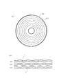
図1(a)に模式的に示すように、ディスク上は、最内周側から最外周側までグルーブGVがスパイラル状に形成される。なお別例として、グルーブGVを同心円状に形成することも可能である。
また、ディスクはCLV(線速度一定)方式で回転駆動されてデータの記録再生が行われるものとしているが、グルーブGVについてもCLVとされる。従って、トラック1周回のグルーブのウォブリング波数はディスク外周側に行くほど多くなる。
Data recording is a groove recording system. That is, a track by a groove (groove) is previously formed on the disk, and recording is performed on this groove.
As schematically shown in FIG. 1A, on the disk, a groove GV is formed in a spiral shape from the innermost circumference side to the outermost circumference side. As another example, the grooves GV can be formed concentrically.
Further, the disk is driven to rotate by the CLV (constant linear velocity) method to record and reproduce data, but the groove GV is also set to CLV. Therefore, the wobbling wave number of the groove for one round of the track increases as it goes to the outer peripheral side of the disk.
このようなグルーブGVは、図1(b)に示すようにウォブリング(蛇行)されて形成されることにより物理アドレスが表現される。
つまりグルーブGVの左右の側壁は、アドレス等に基づいて生成された信号に対応して蛇行している。
グルーブGVとその隣のグルーブGVの間はランドLとされ、上述のようにデータの記録はグルーブGVに行われる。つまりグルーブGVがデータトラックとなる。なお、ランドLをデータトラックとしてデータの記録をランドLに行うようにすることや、グルーブGVとランドLの両方をデータトラックとして用いることも考えられる。
Such a groove GV is formed by wobbling (meandering) as shown in FIG. 1B to express a physical address.
That is, the left and right side walls of the groove GV meander corresponding to a signal generated based on an address or the like.
A land L is formed between the groove GV and the adjacent groove GV, and data is recorded in the groove GV as described above. That is, the groove GV becomes a data track. It is also conceivable to record data on the land L using the land L as a data track, or to use both the groove GV and the land L as data tracks.
図2は、ディスク全体のレイアウト(領域構成)を示す。
ディスク上の領域としては、内周側からリードインゾーン、データゾーン、リードアウトゾーンが配される。
また、記録・再生に関する領域構成としてみれば。リードインゾーンの内周側がPBゾーン(再生専用領域)、リードインゾーンの外周側からリードアウトゾーンまでがRWゾーン(記録再生領域)とされる。
FIG. 2 shows the layout (area configuration) of the entire disc.
As an area on the disc, a lead-in zone, a data zone, and a lead-out zone are arranged from the inner peripheral side.
If you look at the area structure related to recording and playback. The inner circumference side of the lead-in zone is a PB zone (reproduction-only area), and the outer circumference side of the lead-in zone to the lead-out zone is an RW zone (recording / reproduction area).
リードインゾーンは、半径24mmより内側に位置する。そして半径22.3〜23.1mmがプリレコーデッドデータゾーンとされる。
プリレコーデッドデータゾーンは、あらかじめコピープロテクションにつかう情報等(プリレコーデッド情報)を、ディスク上にスパイラル状に形成されたグルーブをウォブリングすることによって記録してある。これは書換不能な再生専用の情報であり、つまりプリレコーデッドデータゾーンが上記PBゾーン(再生専用領域)となる。
The lead-in zone is located inside a radius of 24 mm. A radius of 22.3 to 23.1 mm is set as a prerecorded data zone.
In the pre-recorded data zone, information used for copy protection (pre-recorded information) is recorded in advance by wobbling a groove formed in a spiral shape on the disk. This is reproduction-only information that cannot be rewritten, that is, the prerecorded data zone becomes the PB zone (reproduction-only area).
プリレコーデッドデータゾーンにおいてプリレコーデッド情報として例えばコピープロテクション情報が記録されるが、このコピープロテクション情報を用いて、例えば次のようなことが行われる。
本例にかかる光ディスクシステムでは、登録されたドライブ装置メーカー、ディスクメーカーがビジネスを行うことができ、その登録されたことを示す、メディアキー、あるいは、ドライブキーを有している。
ハックされた場合、そのドライブキー或いはメディアキーがコピープロテクション情報として記録される。このメディアキー、ドライブキーを有した、メディア或いはドライブは、この情報により、記録再生をすることをできなくすることができる。
For example, copy protection information is recorded as prerecorded information in the prerecorded data zone. For example, the following is performed using this copy protection information.
In the optical disc system according to this example, registered drive device manufacturers and disc manufacturers can conduct business, and have a media key or a drive key indicating that the registration has been performed.
When hacked, the drive key or media key is recorded as copy protection information. With this information, the media or drive having the media key and the drive key can be made unrecordable.
リードインゾーンにおいて半径23.1〜24mmにはテストライトエリア及びディフェクトマネジメントエリアが設けられる。
テストライトエリアは記録/再生時のレーザパワー等、フェーズチェンジマークの記録再生条件を設定する際の試し書きなどにつかわれる。
ディフェクトマネジメントエリアはディスク上のディフェクト情報を管理する情報を記録再生する。
In the lead-in zone, a test write area and a defect management area are provided at a radius of 23.1 to 24 mm.
The test write area is used for test writing when setting recording / playback conditions for phase change marks such as laser power during recording / playback.
The defect management area records and reproduces information for managing defect information on the disc.
半径24.0〜58.0mmがデータゾーンとされる。データゾーンは、実際にユーザーデータがフェイズチェンジマークにより記録再生される領域である。
半径58.0〜58.5mmはリードアウトゾーンとされる。リードアウトゾーンは、リードインゾーンと同様のディフェクトマネジメントエリアが設けられたり、また、シークの際、オーバーランしてもよいようにバッファエリアとしてつかわれる。
半径23.1mm、つまりテストライトエリアから、リードアウトゾーンまでが、フェイズチェンジマークが記録再生されるRWゾーン(記録再生領域)とされる。
A radius of 24.0 to 58.0 mm is taken as a data zone. The data zone is an area where user data is actually recorded and reproduced by phase change marks.
A radius of 58.0 to 58.5 mm is a lead-out zone. The lead-out zone is provided with a defect management area similar to the lead-in zone, and is used as a buffer area so that overrun may occur during seek.
A radius of 23.1 mm, that is, from the test write area to the lead-out zone is an RW zone (recording / reproducing area) where the phase change mark is recorded / reproduced.
図3にRWゾーンとPBゾーンのトラックの様子を示す。図3(a)はRWゾーンにおけるグルーブのウォブリングを、図3(b)はPBゾーンにおけるグルーブのウォブリングを、それぞれ示している。 FIG. 3 shows the tracks in the RW zone and the PB zone. 3A shows groove wobbling in the RW zone, and FIG. 3B shows groove wobbling in the PB zone.
RWゾーンでは、あらかじめアドレス情報(ADIP)を、トラッキングを行うために、ディスク上にスパイラル状に形成されたグルーブをウォブリングすることによって、形成してある。
アドレス情報を形成したグルーブには、フェーズチェンジマークにより情報を記録再生する。
図3(a)に示すように、RWゾーンにおけるグルーブ、つまりADIPアドレス情報を形成したグルーブトラックは、トラックピッチTP=0.32μmとされている。
このトラック上にはフェイズチェンジマークによるレコーディングマークが記録されるが、フェーズチェンジマークはRLL(1,7)PP変調方式(RLL;Run Length Limited、PP:Parity preserve/Prohibit rmtr(repeated minimum transition runlength))等により、線密度0.12μm/bit、0.08μm/ch bitで記録される。
1chビットを1Tとすると、マーク長は2Tから8Tで最短マーク長は2Tである。
アドレス情報は、ウォブリング周期を69Tとし、ウォブリング振幅WAはおよそ20nm(p-p)である。
In the RW zone, address information (ADIP) is previously formed by wobbling a groove formed in a spiral shape on the disk in order to perform tracking.
Information is recorded / reproduced by a phase change mark in the groove in which the address information is formed.
As shown in FIG. 3A, a groove in the RW zone, that is, a groove track on which ADIP address information is formed has a track pitch TP = 0.32 μm.
A recording mark by a phase change mark is recorded on this track, but the phase change mark is an RLL (1, 7) PP modulation method (RLL: Run Length Limited, PP: Parity preserve / Prohibit rmtr (repeated minimum transition runlength)). ) And the like are recorded at a linear density of 0.12 μm / bit and 0.08 μm / ch bit.
Assuming that 1ch bit is 1T, the mark length is 2T to 8T, and the shortest mark length is 2T.
The address information has a wobbling period of 69T and a wobbling amplitude WA of about 20 nm (pp).
アドレス情報と、フェーズチェンジマークは、その周波数帯域が重ならないようにしており、これによってそれぞれの検出に影響を与えないようにしてある。
アドレス情報のウォブリングのCNR(carrier noise ratio)はバンド幅30KHzのとき、記録後30dBであり、アドレスエラーレートは節動(ディスクのスキュー,デフォーカス、外乱等)による影響を含めて1×10⁻³以下である。
The address information and the phase change mark are arranged so that their frequency bands do not overlap with each other, thereby preventing each detection from being affected.
The CNR (carrier noise ratio) of wobbling of address information is 30 dB after recording when the bandwidth is 30 KHz, and the address error rate is 1 × 10 − including the influence of movement (disk skew, defocus, disturbance, etc.). 3 or less.
一方、図3(b)のPBゾーンにおけるグルーブによるトラックは、上記図3(a)のRWゾーンのグルーブによるトラックより、トラックピッチが広く、ウォブリング振幅が大きいものとされている。
即ちトラックピッチTP=0.35μmであり、ウォブリング周期は36T、ウォブリング振幅WAはおよそ40nm(p-p)とされている。ウォブリング周期が36Tとされることはプリレコーデット情報の記録線密度はADIP情報の記録線密度より高くなっていることを意味する。また、フェーズチェンジマークは最短2Tであるから、プリレコーデッド情報の記録線密度はフェーズチェンジマークの記録線密度より低い。
このPBゾーンのトラックにはフェーズチェンジマークを記録しない。
On the other hand, the track by the groove in the PB zone of FIG. 3B has a wider track pitch and a larger wobbling amplitude than the track by the groove of the RW zone of FIG.
That is, the track pitch TP = 0.35 μm, the wobbling period is 36 T, and the wobbling amplitude WA is approximately 40 nm (pp). A wobbling period of 36T means that the recording linear density of pre-recorded information is higher than the recording linear density of ADIP information. Further, since the phase change mark is 2T at the shortest, the recording linear density of the prerecorded information is lower than the recording linear density of the phase change mark.
No phase change mark is recorded on this PB zone track.
ウォブリング波形は、RWゾーンでは正弦波状に形成するが、PBゾーンでは、正弦波状か或いは矩形波状で記録することができる。 The wobbling waveform is formed in a sine wave shape in the RW zone, but can be recorded in a sine wave shape or a rectangular wave shape in the PB zone.
フェーズチェンジマークは、バンド幅30KHzのときCNR50dB程度の信号品質であれば、データにECC(エラー訂正コード)をつけて記録再生することで、エラー訂正後のシンボルエラーレートを1×10-16以下を達成でき、データの記録再生として使えることが知られている。
ADIPアドレス情報についてのウォブルのCNRはバンド幅30KHzのとき、フェイズチェンジマークの未記録状態で35dBである。
アドレス情報としては、いわゆる連続性判別に基づく内挿保護を行うことなどによりこの程度の信号品質で十分であるが、PBゾーンに記録するプリレコーデッド情報については、フェイズチェンジマークと同等のCNR50dB以上の信号品質は確保したい。このため、図3(b)に示したようにPBゾーンでは、RWゾーンにおけるグルーブとは物理的に異なるグルーブを形成するものである。
If the signal quality is about CNR 50 dB when the bandwidth is 30 KHz, the phase change mark can be recorded / reproduced with ECC (error correction code) added to the data so that the symbol error rate after error correction is 1 × 10 −16 or less It is known that it can be used for data recording and reproduction.
The wobble CNR for the ADIP address information is 35 dB when the phase change mark is not recorded when the bandwidth is 30 KHz.
As address information, this level of signal quality is sufficient by performing interpolation protection based on so-called continuity discrimination, etc., but for pre-recorded information recorded in the PB zone, CNR 50 dB or more equivalent to the phase change mark I want to ensure the signal quality. Therefore, as shown in FIG. 3B, in the PB zone, a groove physically different from the groove in the RW zone is formed.
まず、トラックピッチを広くすることにより、となりのトラックからのクロストークをおさえることができ、ウォブル振幅を2倍にすることにより、CNRを+6dB改善できる。
さらにウォブル波形として矩形波をつかうことによって、CNRを+2dB改善できる。
あわせてCNRは43dBである。
フェーズチェンジマークとプリレコーデッドデータゾーンのウォブルの記録帯域の違いは、ウォブル18T(18Tは36Tの半分);フェイズチェンジマーク2Tで、この点で9.5dB得られる。
従ってプリレコーデッド情報としてのCNRは52.5dB相当であり、となりのトラックからのクロストークとして−2dBを見積もっても、CNR50.5dB相当である。つまり、ほぼフェーズチェンジマークと同程度の信号品質となり、ウォブリング信号をプリレコーデッド情報の記録再生に用いることが十分に適切となる。
First, by widening the track pitch, crosstalk from the adjacent track can be suppressed, and by doubling the wobble amplitude, the CNR can be improved by +6 dB.
Furthermore, CNR can be improved by +2 dB by using a rectangular wave as a wobble waveform.
In addition, the CNR is 43 dB.
The difference in the wobble recording band between the phase change mark and the pre-recorded data zone is wobble 18T (18T is half of 36T);
Therefore, the CNR as prerecorded information is equivalent to 52.5 dB, and even if -2 dB is estimated as crosstalk from the adjacent track, it is equivalent to CNR 50.5 dB. That is, the signal quality is substantially the same as that of the phase change mark, and it is sufficiently appropriate to use the wobbling signal for recording / reproducing prerecorded information.
1−2.プリレコーデッド情報
図4に、プリレコーデッドデータゾーンにおけるウォブリンググルーブを形成するための、プリレコーデッド情報の変調方法を示す。
変調はFMコードをつかう。
図4(a)にデータビット、図4(b)にチャンネルクロック、図4(c)にFMコード、図4(d)にウォブル波形を縦に並べて示している。
データの1bitは2ch(2チャンネルクロック)であり、ビット情報が「1」のとき、FMコードはチャンネルクロックの1/2の周波数とされる。
またビット情報が「0」のとき、FMコードはビット情報「1」の1/2の周波数であらわされる。
ウォブル波形としては、FMコードを矩形波を直接記録することもあるが、図4(d)に示すように正弦波状の波形で記録することもある。
1-2. Pre-Recorded Information FIG. 4 shows a pre-recorded information modulation method for forming a wobbling groove in the pre-recorded data zone.
The modulation uses FM codes.
FIG. 4A shows the data bits, FIG. 4B shows the channel clock, FIG. 4C shows the FM code, and FIG. 4D shows the wobble waveform vertically.
One bit of data is 2ch (2-channel clock), and when the bit information is “1”, the FM code has a frequency half that of the channel clock.
When the bit information is “0”, the FM code is represented by a frequency that is ½ of the bit information “1”.
As the wobble waveform, the FM code may be directly recorded as a rectangular wave, but may be recorded as a sinusoidal waveform as shown in FIG.
なお、FMコード及びウォブル波形は図4(c)(d)とは逆極性のパターンとして、図4(e)(f)に示すパターンとしても良い。 Note that the FM code and the wobble waveform may be patterns opposite in polarity to those shown in FIGS. 4C and 4D, and the patterns shown in FIGS. 4E and 4F.
上記のようなFMコード変調のルールにおいて、図4(g)のようにデータビットストリームが「10110010」とされているときのFMコード波形、およびウォブル波形(正弦波状波形)は図4(h)(i)に示すようになる。
なお、図4(e)(f)に示すパターンに対応した場合は、図4(j)(k)に示すようになる。
In the FM code modulation rule as described above, the FM code waveform and the wobble waveform (sinusoidal waveform) when the data bit stream is “10110010” as shown in FIG. 4G are shown in FIG. As shown in (i).
In addition, when it corresponds to the pattern shown in FIGS. 4E and 4F, it becomes as shown in FIGS. 4J and 4K.
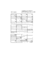
図5,図6,図7により、フェイズチェンジマーク及びプリレコーデッド情報についてのECCフォーマットを説明する。
まず図5には、フェーズチェンジマークで記録再生するメインデータ(ユーザーデータ)についてのECCフォーマットを示している。
The ECC format for the phase change mark and the pre-recorded information will be described with reference to FIGS.
First, FIG. 5 shows an ECC format for main data (user data) to be recorded / reproduced with a phase change mark.
ECC(エラー訂正コード)としては、メインデータ64KB(=1セクターの2048バイト×32セクター)に対するLDC(long distance code)と、BIS(Burst indicator subcode)の2つがある。
There are two types of ECC (Error Correction Code): LDC (long distance code) for
図5(a)に示すメインデータ64KBについては、図5(b)のようにECCエンコードされる。即ちメインデータは1セクタ2048Bについて4BのEDC(error detection code)を付加し、32セクタに対し、LDCを符号化する。LDCはRS(248,216,33)、符号長248、データ216、ディスタンス33のRS(reed solomon)コードである。304の符号語がある。
The
一方、BISは、図5(c)に示す720Bのデータに対して、図5(d)のようにECCエンコードされる。即ちRS(62,30,33)、符号長62、データ30、ディスタンス33のRS(reed solomon)コードである。24の符号語がある。
On the other hand, BIS is ECC-encoded as shown in FIG. 5D with respect to 720B data shown in FIG. That is, the RS (62, 30, 33),
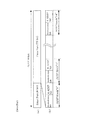
図7(a)にRWゾーンにおけるメインデータについてのフレーム構造を示している。
上記LDCのデータと、BISは図示するフレーム構造を構成する。即ち1フレームにつき、データ(38B)、BIS(1B)、データ(38B)、BIS(1B)、データ(38B)が配されて155Bの構造となる。つまり1フレームは38B×4の152Bのデータと、38BごとにBISが1B挿入されて構成される。
フレームシンクFS(フレーム同期信号)は、1フレーム155Bの先頭に配される。1つのブロックには496のフレームがある。
LDCデータは、0,2,・・・の偶数番目の符号語が、0,2,・・・の偶数番目のフレームに位置し、1,3,・・・の奇数番目の符号語が、1,3,・・・の奇数番目のフレームに位置する。
FIG. 7A shows a frame structure for main data in the RW zone.
The LDC data and the BIS constitute the frame structure shown in the figure. That is, for each frame, data (38B), BIS (1B), data (38B), BIS (1B), and data (38B) are arranged to form a 155B structure. That is, one frame is configured by inserting 38B × 4 152B data and 1B of BIS for each 38B.
A frame sync FS (frame synchronization signal) is arranged at the head of one frame 155B. There are 496 frames in one block.
In the LDC data, even-numbered
BISはLDCの符号より訂正能力が非常に優れた符号をもちいており、ほぼ、すべて訂正される。つまり符号長62に対してディスタンスが33という符号を用いている。
このため、エラーが検出されたBISのシンボルは次のように使うことができる。
ECCのデコードの際、BISを先にデコードする。図7(a)のフレーム構造において隣接したBISあるいはフレームシンクFSの2つがエラーの場合、両者のあいだにはさまれたデータ38Bはバーストエラーとみなされる。このデータ38Bにはそれぞれエラーポインタが付加される。LDCではこのエラーポインタをつかって、ポインターイレージャ訂正をおこなう。
これによりLDCだけの訂正より、訂正能力を上げることができる。
BISにはアドレス情報等が含まれている。このアドレスは、ROMタイプディスク等で、ウォブリンググルーブによるアドレス情報がない場合等につかわれる。
The BIS uses a code having a much better correction capability than the LDC code, and almost all are corrected. That is, a code having a distance of 33 with respect to the
Therefore, the BIS symbol in which an error is detected can be used as follows.
When decoding ECC, BIS is decoded first. In the frame structure of FIG. 7A, when two adjacent BIS or frame sync FS are in error, the data 38B sandwiched between the two is regarded as a burst error. An error pointer is added to each data 38B. The LDC performs pointer erasure correction using this error pointer.
As a result, the correction capability can be improved as compared with correction using only LDC.
The BIS includes address information and the like. This address is used when there is no address information by a wobbling groove on a ROM type disk or the like.
次に図6にプリレコーデッド情報についてのECCフォーマットを示す。
この場合ECCには、メインデータ4KB(1セクタ2048B×2セクタ)に対するLDC(long distance code)とBIS(Burst indicator subcode)の2つがある。
Next, FIG. 6 shows an ECC format for pre-recorded information.
In this case, there are two ECCs: LDC (long distance code) and BIS (Burst indicator subcode) for
図6(a)に示すプリレコーデッド情報としてのデータ4KBについては、図6(b)のようにECCエンコードされる。即ちメインデータは1セクタ2048Bについて4BのEDC(error detection code)を付加し、2セクタに対し、LDCを符号化する。LDCはRS(248,216,33)、符号長248、データ216、ディスタンス33のRS(reed solomon)コードである。19の符号語がある。
The data 4KB as the prerecorded information shown in FIG. 6A is ECC encoded as shown in FIG. 6B. That is, the main data adds 4B EDC (error detection code) for one sector 2048B, and encodes LDC for two sectors. LDC is an RS (reed solomon) code of RS (248, 216, 33),
一方、BISは、図6(c)に示す120Bのデータに対して、図6(d)のようにECCエンコードされる。即ちRS(62,30,33)、符号長62、データ30、ディスタンス33のRS(reed solomon)コードである。4つの符号語がある。
On the other hand, BIS is ECC-encoded as shown in FIG. 6D with respect to the 120B data shown in FIG. That is, the RS (62, 30, 33),
図7(b)にPBゾーンにおけるプリレコーデッド情報についてのフレーム構造を示している。
上記LDCのデータと、BISは図示するフレーム構造を構成する。即ち1フレームにつき、フレームシンクFS(1B)、データ(10B)、BIS(1B)、データ(9B)が配されて21Bの構造となる。つまり1フレームは19Bのデータと、BISが1B挿入されて構成される。
フレームシンクFS(フレーム同期信号)は、1フレームの先頭に配される。1つのブロックには248のフレームがある。
FIG. 7B shows a frame structure for prerecorded information in the PB zone.
The LDC data and the BIS constitute the frame structure shown in the figure. That is, for each frame, the frame sync FS (1B), data (10B), BIS (1B), and data (9B) are arranged to form a 21B structure. That is, one frame is configured by inserting 19B data and 1B BIS.
A frame sync FS (frame synchronization signal) is arranged at the head of one frame. There are 248 frames in one block.
この場合もBISはLDCの符号より訂正能力が非常に優れた符号をもちいており、ほぼ、すべて訂正される。このため、エラーが検出されたBISのシンボルは次のように使うことができる。
ECCのデコードの際、BISを先にデコードする。隣接したBIS或いはフレームシンクFSの2つがエラーの場合、両者のあいだにはさまれたデータ10B、あるいは9Bはバーストエラーとみなされる。このデータ10B、あるいは9Bにはそれぞれエラーポインタが付加される。LDCではこのエラーポインタをつかって、ポインターイレージャ訂正をおこなう。
これによりLDCだけの訂正より、訂正能力をあげることができる。
Also in this case, the BIS uses a code having a correction capability much better than that of the LDC code, and almost all are corrected. Therefore, the BIS symbol in which an error is detected can be used as follows.
When decoding ECC, BIS is decoded first. When two adjacent BISs or frame sync FSs are in error, the data 10B or 9B sandwiched between them is regarded as a burst error. An error pointer is added to each of the data 10B or 9B. The LDC performs pointer erasure correction using this error pointer.
As a result, the correction capability can be improved rather than the correction only by the LDC.
BISにはアドレス情報等が含まれている。プリレコーデッドデータゾーンではプリレコーデッド情報がウォブリンググルーブによって記録され、従ってウォブリンググルーブによるアドレス情報は無いため、このBISにあるアドレスがアクセスのために使われる。 The BIS includes address information and the like. In the pre-recorded data zone, pre-recorded information is recorded by the wobbling groove, and therefore there is no address information by the wobbling groove, so the address in this BIS is used for access.
図5,図6からわかるように、フェイズチェンジマークによるデータとプリレコーデッド情報は、ECCフォーマットとしては、同一の符号及び構造が採用される。
これは、プリレコーデッド情報のECCデコード処理は、フェイズチェンジマークによるデータ再生時のECCデコード処理を行う回路系で実行でき、ディスクドライブ装置としてはハードウエア構成の効率化を図ることができることを意味する。
As can be seen from FIGS. 5 and 6, the same code and structure are adopted as the ECC format for the data by the phase change mark and the pre-recorded information.
This means that ECC decoding processing of pre-recorded information can be executed by a circuit system that performs ECC decoding processing at the time of data reproduction by phase change marks, and the disk drive device can improve the efficiency of the hardware configuration. To do.
図8はプリレコーデッドデータゾーンのフレームシンクを示す。
フレームシンクFSとしては7種類のフレームシンクFS0〜FS6がある。各フレームシンクFS0〜FS6はFMコード変調のアウトオブルールとしてのパターンを用いた、シンクボディ「11001001」の8チャンネルビットと、7種類のフレームシンクFS0〜FS6のそれぞれについてのシンクIDの8チャンネルビットの合計16チャンネルビットより構成される。
FIG. 8 shows the frame sync of the prerecorded data zone.
As the frame sync FS, there are seven types of frame syncs FS0 to FS6. Each frame sync FS0 to FS6 uses a pattern as an out-of-rule of FM code modulation, 8 channel bits of the sync body “11001001”, and 8 channel bits of a sync ID for each of the seven types of frame syncs FS0 to FS6 The total of 16 channel bits.
シンクIDはデータビットであらわすと、たとえば、フレームシンクFS0は「000」の3bitとパリティ1bit(ここでは0)よりあらわされ、これがFMコード変調され「10101010」となる。
他のシンクIDも同様に、3bitのデータビットとパリティ1bitによりあらわされ、FMコード変調される。
フレームシンクFSは記録の際に、NRZI変換されて記録される。
When the sync ID is represented by a data bit, for example, the frame sync FS0 is represented by 3 bits of “000” and 1 bit of parity (0 in this case), which is FM code modulated to “10101010”.
Similarly, other sync IDs are represented by 3 bits of data bits and 1 bit of parity, and are FM code modulated.
The frame sync FS is recorded after NRZI conversion at the time of recording.
図9にフレームシンクのマッピングを示す。
上記図7(b)に示したプリレコーデッド情報の1ECCブロックの248フレームは、8つの31フレームづつのアドレスフレームに分割される。
各アドレスフレームとも、0から30のフレームナンバをもつ。フレームナンバ「0」には、他のフレームシンクには使われない特別のフレームシンクとしてFS0を用いる。このフレームシンクFS0により、アドレスフレームの先頭を見い出すことができ、アドレス同期を行うことができる。
フレームナンバ「1」から「30」には、図9に示す順番でフレームシンク(FS1〜FS6)を配置する。このフレームシンクの並ぶ順番により、先頭のフレームシンクFS0が特定できなくとも、アドレスフレームの先頭を特定することもできる。
FIG. 9 shows the frame sync mapping.
The 248 frames of one ECC block of the pre-recorded information shown in FIG. 7B is divided into eight 31-frame address frames.
Each address frame has a frame number from 0 to 30. For the frame number “0”, FS0 is used as a special frame sync that is not used for other frame syncs. With this frame sync FS0, the head of the address frame can be found and address synchronization can be performed.
In the frame numbers “1” to “30”, the frame syncs (FS1 to FS6) are arranged in the order shown in FIG. Depending on the order in which the frame syncs are arranged, the head of the address frame can be specified even if the head frame sync FS0 cannot be specified.
ところで、プリレコーデッドデータゾーンではBISに含まれるアドレスがアクセスのために使われると述べた。
図10にプリレコーデッドデータゾーンのECCブロックにおいてBISに入れる情報を示している。
BIS情報は、アドレスとユーザーコントロールデータより構成される。
By the way, it has been stated that in the prerecorded data zone, the address included in the BIS is used for access.
FIG. 10 shows information entered in the BIS in the ECC block of the prerecorded data zone.
The BIS information is composed of an address and user control data.
BISにおけるアドレスフィールドを図10(a)に示す。アドレスとしては、1ECCブロックの中に、8アドレスフィールド(#0〜#7)ある。
1つのアドレスフィールドは9byteより構成される。例えばアドレスフィールド#0は、A0-0〜A0-8の9バイトで構成される。
各アドレスフィールドのMSB4ByteにはAUN(address unit number)というECCブロックアドレスを示すアドレス値が配される。
また各アドレスフィールドの5バイト目には、その下位3bit(3Lsbit)には、アドレスフィールドナンバが配される。
さらに各アドレスフィールドの下位4Byteには各アドレスフィールドに対するパリティが配される。
The address field in BIS is shown in FIG. As addresses, there are 8 address fields (# 0 to # 7) in one ECC block.
One address field is composed of 9 bytes. For example, the
In the
In the fifth byte of each address field, an address field number is arranged in the lower 3 bits (3 Lsbit).
Further, the parity for each address field is arranged in the lower 4 bytes of each address field.
一方、BISにおけるユーザーコントロールデータは、図10(b)のように1ECCブロック内に2ユニット(#0,#1)ある。
ユーザーコントロールデータの1ユニットは24byteより構成される。例えばユニット#0は、UC0-0〜UC0-23の24バイトで構成される。
このユーザーコントロールデータは将来のシステムに使われるようにリザーブしてある。
On the other hand, user control data in BIS is 2 units (# 0, # 1) in one ECC block as shown in FIG.
One unit of user control data is composed of 24 bytes. For example,
This user control data is reserved for use in future systems.
図11にプリレコーデッドデータゾーンのECCブロックのBIS、つまりBISクラスタのBIS情報の構成を示す。
BISクラスタは、4訂正符号より構成される。ここではパリティを除いた情報のみを示す。符号は、図のカラム(column)方向に構成される。BISクラスタは4カラムで構成される。
1カラムの情報は、アドレスが18row、ユーザーコントロールデータ12rowのトータル30rowより構成される。
FIG. 11 shows the configuration of the BIS of the ECC block in the prerecorded data zone, that is, the BIS information of the BIS cluster.
The BIS cluster is composed of 4 correction codes. Here, only information excluding parity is shown. The code is configured in the column direction of the figure. A BIS cluster consists of four columns.
The information of one column is composed of a total of 30 rows of an address of 18 rows and
各アドレスフィールド#0〜#7のアドレスは、図示するように4カラムにインタリーブされて配置される。ここではアドレスフィールド#0、#1、#2までを示しているのみであるが、例えばアドレスフィールド#0を構成するA0-0〜A0-8の9バイトは、図中斜線部として示す位置に配置されることになる。
また、ユーザーコントロールデータも図のように12rowの範囲にユニット#0,#1がそれぞれ配置される。
記録する際は、たとえば、図に示すアドレスフィールド#0が順次配置されるように、BISクラスタのななめ方向に記録される。
The addresses of the address fields # 0 to # 7 are arranged to be interleaved into 4 columns as shown in the figure. Here, only the address fields # 0, # 1, and # 2 are shown. For example, the 9 bytes of A0-0 to A0-8 constituting the
In the user control data,
When recording, for example, recording is performed in the tan direction of the BIS cluster so that the
図12にパリティを含めたBISクラスタ全体を示す。
BISのエラー訂正符号は上述したようにRS(62,30,33)である。BISクラスタには符号長62シンボルの符号が4符号あり、1符号は図中矢印で示すように縦方向ににエンコードされる。
FIG. 12 shows the entire BIS cluster including parity.
The error correction code of BIS is RS (62, 30, 33) as described above. The BIS cluster has four codes with a code length of 62 symbols, and one code is encoded in the vertical direction as indicated by an arrow in the figure.
図13はパリティを含めたBISクラスタの248シンボルの記録する順番を示している。
BISクラスタは記録の際、8アドレスユニットとして記録される。
1つのアドレスユニットは図14に示すように31シンボルより構成される。
各アドレスユニットの先頭9byteには、各アドレスユニット番号に対応した番号の、アドレスフィールド#nとしての9byte(An-0〜An-8)が配置される。例えばアドレスユニット0にはアドレスフィールド#0(A0-0〜A0-8)が配置される。
例えばこのようなアドレスユニット0としての31シンボルは、図13において斜線部として示すように配置されることになる。
FIG. 13 shows the order of recording 248 symbols of the BIS cluster including parity.
A BIS cluster is recorded as an 8-address unit during recording.
One address unit is composed of 31 symbols as shown in FIG.
In the first 9 bytes of each address unit, 9 bytes (An-0 to An-8) as an address field #n of a number corresponding to each address unit number are arranged. For example, address field # 0 (A0-0 to A0-8) is arranged in
For example, 31 symbols as such an
1アドレスユニットの31シンボルは、上述した31アドレスフレームに対応し、図9のフレームナンバーとフレームシンクパターン(FS0〜FS6)により、フレームシンクFS0のタイミングから、1アドレスユニットのタイミングを検出することができ、これにより、各アドレスフィールド(#0〜#7)のアドレスを再生することができる。 31 symbols of one address unit correspond to the 31 address frame described above, and the timing of one address unit can be detected from the timing of frame sync FS0 by the frame number and frame sync pattern (FS0 to FS6) of FIG. Thus, the addresses in the address fields (# 0 to # 7) can be reproduced.
1−3.ADIPアドレス
続いて、RWゾーンにおけるウォブリンググルーブとして記録されるADIPアドレスについて説明する。
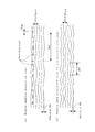
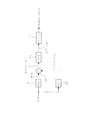
図15は、グルーブをウォブリングしたADIPアドレスの変調方法として、FSK変調の一つであるMSK(minimum shift keying)変調を用いたものを示している。
1-3. ADIP Address Next, an ADIP address recorded as a wobbling groove in the RW zone will be described.
FIG. 15 shows a method using MSK (minimum shift keying) modulation, which is one of FSK modulation, as a method of modulating an ADIP address in which a groove is wobbled.
データの検出長は2ウォブル区間を単位とする。なお、1ウォブル区間とはキャリア周波数によるウォブルの1周期区間である。
アドレス等のデータは、図15(a)(b)に示すように、記録前に、1ウォブルを単位として、差動符号化する。
つまり、記録前の差動符号化後のプリコードデータにおいて、データが“1”のエッジの立ち上がりと立ち下がりの1ウォブル期間が、“1”になる。
このようなプリコードデータをMSK変調したMSKストリームでは、図15(c)のように、プリコードデータが“0”のとき、キャリアであるcosωtあるいは−cosωtとなり、プリコードデータが“1”のとき、キャリアの周波数の1.5倍のcos1.5ωtあるいは−cos1.5ωtとなる。
キャリアの周期は図に示すように、記録再生するフェーズチェンジデータの1チャンネルビット長を1chとすると、69chである。
The detection length of data is in units of 2 wobble sections. Note that one wobble section is one period section of wobble with a carrier frequency.
As shown in FIGS. 15A and 15B, data such as an address is differentially encoded in units of one wobble before recording.
That is, in the pre-coded data after differential encoding before recording, one wobble period of rising and falling edges of data “1” is “1”.
In an MSK stream obtained by MSK modulating such precode data, as shown in FIG. 15C, when the precode data is “0”, the carrier is cosωt or −cosωt, and the precode data is “1”. Then, it becomes cos1.5ωt or −cos1.5ωt which is 1.5 times the frequency of the carrier.
As shown in the figure, the carrier period is 69 ch, where the 1 channel bit length of phase change data to be recorded / reproduced is 1 ch.
本例の場合、データの記録単位である1つのRUB(recording unit block:記録再生クラスタ)に対しては、ADIPアドレスとして3つのアドレスが入るものとされる。
図16にその様子を示す。RUB(記録再生クラスタ)は、図7(a)に示したデータのECCブロックの496フレームに、その前後に2フレームのPLL等のためのリンクエリアを付加した498フレームとして記録再生の単位である。
そして図16(a)のように1つのRUBに相当する区間において、ADIPとしては3つのアドレスブロックが含まれることになる。
1つのアドレスブロックは83ビットから形成される。
In the case of this example, one RUB (recording unit block: recording / reproducing cluster) which is a data recording unit is assumed to have three addresses as ADIP addresses.
This is shown in FIG. The RUB (recording / reproducing cluster) is a unit of recording / reproducing as 498 frames obtained by adding a link area for two frames of PLL or the like to the 496 frames of the ECC block of the data shown in FIG. .
Then, in the section corresponding to one RUB as shown in FIG. 16A, three address blocks are included as ADIP.
One address block is formed from 83 bits.
図16(b)に1つのアドレスブロックの構成を示している。83ビットのアドレスブロックは、8ビットのシンクパート(同期信号パート)と、75ビットのデータパートからなる。
シンクパートの8ビットでは、モノトーンビット(1ビット)とシンクビット(1ビット)によるシンクブロックが4単位形成される。
データパートの75ビットでは、モノトーンビット(1ビット)とADIPビット(4ビット)によるADIPブロックが15単位形成される。
モノトーンビット、シンクビット、及びADIPビットは、それぞれ56ウォブル期間のウォブルで形成される。これらのビットの先頭にはビットシンクの為のMSKマークが配される。
そしてモノトーンビットはMSKマークに続いて、キャリア周波数によるウォブルが連続して形成される。シンクビット及びADIPビットは後述するが、MSKマークに続いて、MSK変調波形によるウォブルを有して形成される。
FIG. 16B shows the configuration of one address block. The 83-bit address block is composed of an 8-bit sync part (synchronization signal part) and a 75-bit data part.
In the 8 bits of the sync part, 4 units of sync blocks are formed by monotone bits (1 bit) and sync bits (1 bit).
In the 75 bits of the data part, 15 units of ADIP blocks are formed by monotone bits (1 bit) and ADIP bits (4 bits).
The monotone bit, the sync bit, and the ADIP bit are each formed by 56 wobble periods. An MSK mark for bit sync is arranged at the head of these bits.
In the monotone bit, a wobble with a carrier frequency is continuously formed following the MSK mark. Although the sync bit and the ADIP bit will be described later, the sync bit and the ADIP bit are formed with a wobble by an MSK modulation waveform following the MSK mark.
まずシンクパートの構成を図17で説明する。
図17(a)(b)からわかるように、8ビットのシンクパートは、4つのシンクブロック(sync block“0”“1”“2”“3”)から形成される。各シンクブロックは2ビットである。
First, the configuration of the sync part will be described with reference to FIG.
As can be seen from FIGS. 17A and 17B, the 8-bit sync part is formed of four sync blocks (sync block “0” “1” “2” “3”). Each sync block is 2 bits.
sync block“0”は、モノトーンビットとシンク“0”ビットで形成される。
sync block“1”は、モノトーンビットとシンク“1”ビットで形成される。
sync block“2”は、モノトーンビットとシンク“2”ビットで形成される。
sync block“3”は、モノトーンビットとシンク“3”ビットで形成される。
The sync block “0” is formed by a monotone bit and a sync “0” bit.
The sync block “1” is formed of a monotone bit and a sync “1” bit.
The sync block “2” is formed of a monotone bit and a sync “2” bit.
The sync block “3” is formed by a monotone bit and a sync “3” bit.
各シンクブロックにおいて、モノトーンビットは上述したようにキャリアをあらわす単一周波数のウォブルが連続する波形であり、これを図18(a)に示す。即ち56ウォブル期間に、先頭にビットシンクbsとしてのMSKマークが付され、それに続いて単一周波数のウォブルが連続する。
なお図18(a)〜(e)において、それぞれウォブル振幅の下段にMSKマークパターンを示している。
In each sync block, the monotone bit is a waveform in which a single frequency wobble representing a carrier continues as described above, and this is shown in FIG. That is, in the 56 wobble period, an MSK mark as a bit sync bs is added to the head, and subsequently, a single frequency wobble continues.
In FIGS. 18A to 18E, the MSK mark pattern is shown in the lower stage of the wobble amplitude.
シンクビットとしては、上記のようにシンク“0”ビット〜シンク“3”ビットまでの4種類がある。
これら4種類の各シンクビットは、それぞれ図18(b)(c)(d)(e)に示すようなウォブルパターンとされる。
As described above, there are four types of sync bits from sync “0” bit to sync “3” bit.
Each of these four types of sync bits has a wobble pattern as shown in FIGS. 18B, 18C, 18D, and 18E.
図18(b)のシンク“0”ビットは、ビットシンクbsとしてのMSKマークに続いて、16ウォブル区間後にMSKマークがあり、さらに10ウォブル区間後にMSKマークがあるパターンとなる。
シンク“1”ビット〜シンク“3”ビットは、それぞれMSKマークの位置を2ウォブル区間後方にずらしたパターンである。
即ち図18(c)のシンク“1”ビットは、ビットシンクbsとしてのMSKマークに続いて、18ウォブル区間後にMSKマークがあり、さらにその10ウォブル区間後にMSKマークがあるパターンとなる。
図18(d)のシンク“2”ビットは、ビットシンクbsとしてのMSKマークに続いて、20ウォブル区間後にMSKマークがあり、さらにその10ウォブル区間後にMSKマークがあるパターンとなる。
図18(e)のシンク“3”ビットは、ビットシンクbsとしてのMSKマークに続いて、22ウォブル区間後にMSKマークがあり、さらにその10ウォブル区間後にMSKマークがあるパターンとなる。
The sync “0” bit in FIG. 18B has a pattern in which there is an MSK mark after 16 wobble sections and an MSK mark after 10 wobble sections following the MSK mark as the bit sync bs.
The sync “1” bit to the sync “3” bit are patterns in which the position of the MSK mark is shifted backward by 2 wobble sections.
That is, the sync “1” bit in FIG. 18C has a pattern in which there is an MSK mark after 18 wobble sections and an MSK mark after 10 wobble sections following the MSK mark as the bit sync bs.
The sync “2” bit in FIG. 18D has a pattern in which there is an MSK mark after 20 wobble sections, followed by an MSK mark after 10 wobble sections, following the MSK mark as the bit sync bs.
The sync “3” bit in FIG. 18E is a pattern in which there is an MSK mark after 22 wobble sections and an MSK mark after 10 wobble sections following the MSK mark as the bit sync bs.
各シンクパターンは、モノトーンビット及び次に説明するADIPビットに対してユニークなパターンとなっている。このように4つのパターンのシンクビットが、各シンクブロックに配されることになり、ディスクドライブ装置側では、シンクパート区間からこの4つのパターンのシンクユニットのいずれかを検出できれば、同期をとることができるようにされている。 Each sync pattern is a unique pattern for a monotone bit and an ADIP bit described below. In this way, four patterns of sync bits are arranged in each sync block, and if the disk drive device can detect any one of the four patterns of sync units from the sync part section, synchronization is achieved. Have been able to.
次にアドレスブロックにおけるデータパートの構成を図19で説明する。
図19(a)(b)からわかるように、データパートは、15個のADIPブロック(ADIP block“0”〜“14”)から形成される。各ADIPブロックは5ビットである。
Next, the structure of the data part in the address block will be described with reference to FIG.
As can be seen from FIGS. 19A and 19B, the data part is formed of 15 ADIP blocks (ADIP blocks “0” to “14”). Each ADIP block is 5 bits.
5ビットの各ADIPブロックは、モノトーンビットが1ビットとADIPビットが4ビットで構成される。
各ADIPブロックにおいて、シンクブロックの場合と同様に、モノトーンビットは56ウォブル期間において先頭にビットシンクbsとしてのMSKマークが配され、続いてキャリア周波数のウォブルが連続する波形であり、これを図20(a)に示している。
Each 5-bit ADIP block is composed of 1 monotone bit and 4 ADIP bits.
In each ADIP block, as in the case of the sync block, the monotone bit has a waveform in which the MSK mark as the bit sync bs is arranged at the head in the 56 wobble period, and the wobble of the carrier frequency continues, and this is shown in FIG. This is shown in (a).
1つのADIPブロックに4ビットのADIPビットが含まれるため、15個のADIPブロックにより60ADIPビットでアドレス情報が形成される。
ADIPビットとしての「1」及び「0」のパターンを図20(b)(c)に示す。
ADIPビットとしての値が「1」の場合のウォブル波形パターンは、図20(b)に示すように、先頭に配されるビットシンクbsとしてのMSKマークに続いて、12ウォブル区間後方にMSKマークが配される。
ADIPビットとしての値が「0」の場合のウォブル波形パターンは、図20(c)に示すように、先頭に配されるビットシンクbsとしてのMSKマークに続いて、14ウォブル区間後方にMSKマークが配される。
Since one ADIP block includes 4 ADIP bits, 15 ADIP blocks form address information with 60 ADIP bits.
FIGS. 20B and 20C show patterns of “1” and “0” as ADIP bits.
As shown in FIG. 20B, the wobble waveform pattern when the value as the ADIP bit is “1” is the MSK mark behind the 12 wobble section following the MSK mark as the bit sync bs arranged at the head. Is arranged.
As shown in FIG. 20C, the wobble waveform pattern when the value as the ADIP bit is “0” is the MSK mark behind the 14 wobble section following the MSK mark as the bit sync bs arranged at the head. Is arranged.
以上のようにして、ウォブリンググルーブにはMSK変調データが記録されることになるが、このように記録されるADIP情報としてのアドレスフォーマットは図21のようになる。 As described above, MSK modulation data is recorded in the wobbling groove, and the address format as ADIP information recorded in this way is as shown in FIG.
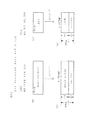
図21によりADIPアドレス情報に対するエラー訂正の方法を示す。
ADIPアドレス情報は36ビットあり、これに対してパリティ24ビットが付加される。
36ビットのADIPアドレス情報は、多層記録用にレイヤナンバ3bit(layer no.bit 0〜layer no.bit2)、RUB(recording unit block)用に19bit(RUB no.bit 0〜layer no.bit 18)、1RUBに対する3つのアドレスブロック用に2bit(address no.bit 0、address no.bit1)とされる。
また、記録再生レーザパワー等の記録条件を記録したdisc ID等、AUXデータとして12bitが用意されている。
FIG. 21 shows an error correction method for ADIP address information.
ADIP address information has 36 bits, and a parity of 24 bits is added thereto.
36-bit ADIP address information consists of 3 bits for layer recording (
In addition, 12 bits are prepared as AUX data such as disc ID in which recording conditions such as recording / reproducing laser power are recorded.
アドレスデータとしてのECC単位は、このように合計60ビットの単位とされ、図示するようにNibble0〜Nibble14の15ニブル(1ニブル=4ビット)で構成される。
エラー訂正方式としては4ビットを1シンボルとした、nibbleベースのリードソロモン符号RS(15,9,7)である。つまり、符号長15ニブル、データ9ニブル、パリティ6ニブルである。
The ECC unit as the address data is a unit of 60 bits in total as described above, and is composed of 15 nibbles (1 nibble = 4 bits) of Nibble0 to Nibble14 as shown.
The error correction method is a nibble-based Reed-Solomon code RS (15, 9, 7) with 4 bits as one symbol. That is, the code length is 15 nibbles, the data is 9 nibbles, and the parity is 6 nibbles.
2.ディスクドライブ装置
次に、上記のようなディスクに対応して記録/再生を行うことのできるディスクドライブ装置を説明していく。
図22はディスクドライブ装置の構成を示す。
図22において、ディスク100は上述した本例のディスクである。
2. Disk drive device
Next, a disk drive device capable of recording / reproducing corresponding to the above disk will be described.
FIG. 22 shows the configuration of the disk drive device.
In FIG. 22, a
ディスク100は、図示しないターンテーブルに積載され、記録/再生動作時においてスピンドルモータ2によって一定線速度(CLV)で回転駆動される。
そして光学ピックアップ1によってディスク100上のRWゾーンにおけるグルーブトラックのウォブリングとして埋め込まれたADIP情報の読み出しがおこなわれる。またPBゾーンにおけるグルーブトラックのウォブリングとして埋め込まれたプリレコーデッド情報の読み出しがおこなわれる。
また記録時には光学ピックアップによってRWゾーンにおけるトラックにユーザーデータがフェイズチェンジマークとして記録され、再生時には光学ピックアップによって記録されたフェイズチェンジマークの読出が行われる。
The
The ADIP information embedded as wobbling of the groove track in the RW zone on the
At the time of recording, user data is recorded as a phase change mark on the track in the RW zone by the optical pickup, and at the time of reproduction, the phase change mark recorded by the optical pickup is read.
ピックアップ1内には、レーザ光源となるレーザダイオードや、反射光を検出するためのフォトディテクタ、レーザ光の出力端となる対物レンズ、レーザ光を対物レンズを介してディスク記録面に照射し、またその反射光をフォトディテクタに導く光学系(図示せず)が形成される。
レーザダイオードは、波長405nmのいわゆる青色レーザを出力する。また光学系によるNAは0.85である。
In the
The laser diode outputs a so-called blue laser having a wavelength of 405 nm. The NA by the optical system is 0.85.
ピックアップ1内において対物レンズは二軸機構によってトラッキング方向及びフォーカス方向に移動可能に保持されている。
またピックアップ1全体はスレッド機構3によりディスク半径方向に移動可能とされている。
またピックアップ1におけるレーザダイオードはレーザドライバ13からのドライブ信号(ドライブ電流)によってレーザ発光駆動される。
In the
The
The laser diode in the
ディスク100からの反射光情報はフォトディテクタによって検出され、受光光量に応じた電気信号とされてマトリクス回路4に供給される。
マトリクス回路4には、フォトディテクタとしての複数の受光素子からの出力電流に対応して電流電圧変換回路、マトリクス演算/増幅回路等を備え、マトリクス演算処理により必要な信号を生成する。
例えば再生データに相当する高周波信号(再生データ信号)、サーボ制御のためのフォーカスエラー信号、トラッキングエラー信号などを生成する。
さらに、グルーブのウォブリングに係る信号、即ちウォブリングを検出する信号としてプッシュプル信号を生成する。
Reflected light information from the
The
For example, a high frequency signal (reproduction data signal) corresponding to reproduction data, a focus error signal for servo control, a tracking error signal, and the like are generated.
Further, a push-pull signal is generated as a signal related to groove wobbling, that is, a signal for detecting wobbling.
マトリクス回路4から出力される再生データ信号はリーダ/ライタ回路5へ、フォーカスエラー信号及びトラッキングエラー信号はサーボ回路11へ、プッシュプル信号はウォブル回路8へ、それぞれ供給される。
The reproduction data signal output from the
リーダ/ライタ回路5は、再生データ信号に対して2値化処理、PLLによる再生クロック生成処理等を行い、フェイズチェンジマークとして読み出されたデータを再生して、変復調回路6に供給する。
変復調回路6は、再生時のデコーダとしての機能部位と、記録時のエンコーダとしての機能部位を備える。
再生時にはデコード処理として、再生クロックに基づいてランレングスリミテッドコードの復調処理を行う。
またECCエンコーダ/デコーダ7は、記録時にエラー訂正コードを付加するECCエンコード処理と、再生時にエラー訂正を行うECCデコード処理を行う。
再生時には、変復調回路6で復調されたデータを内部メモリに取り込んで、エラー検出/訂正処理及びデインターリーブ等の処理を行い、再生データを得る。
ECCエンコーダ/デコーダ7で再生データにまでデコードされたデータは、システムコントローラ10の指示に基づいて、読み出され、AV(Audio-Visual)システム20に転送される。
The reader /
The
At the time of reproduction, as a decoding process, a run-length limited code is demodulated based on the reproduction clock.
The ECC encoder /
At the time of reproduction, the data demodulated by the modulation /
The data decoded up to the reproduction data by the ECC encoder /
グルーブのウォブリングに係る信号としてマトリクス回路4から出力されるプッシュプル信号は、ウォブル回路8において処理される。ADIP情報としてのプッシュプル信号は、ウォブル回路8においてMSK復調され、ADIPアドレスを構成するデータストリームに復調されてアドレスデコーダ9に供給される。
アドレスデコーダ9は、供給されるデータについてのデコードを行い、アドレス値を得て、システムコントローラ10に供給する。
またアドレスデコーダ9はウォブル回路8から供給されるウォブル信号を用いたPLL処理でクロックを生成し、例えば記録時のエンコードクロックとして各部に供給する。
The push-pull signal output from the
The
The
また、グルーブのウォブリングに係る信号としてマトリクス回路4から出力されるプッシュプル信号として、PBゾーンからのプリレコーデッド情報としてのプッシュプル信号は、ウォブル回路8においてバンドパスフィルタ処理が行われてリーダ/ライタ回路5に供給される。そしてフェイズチェンジマークの場合と同様に2値化され、データビットストリームとされた後、ECCエンコーダ/デコーダ7でECCデコード、デインターリーブされて、プリレコーデッド情報としてのデータが抽出される。抽出されたプリレコーデッド情報はシステムコントローラ10に供給される。
システムコントローラ10は、読み出されたプリレコーデッド情報に基づいて、各種設定処理やコピープロテクト処理等を行うことができる。
Further, as a push-pull signal output from the
The
記録時には、AVシステム20から記録データが転送されてくるが、その記録データはECCエンコーダ/デコーダ7におけるメモリに送られてバッファリングされる。
この場合ECCエンコーダ/デコーダ7は、バファリングされた記録データのエンコード処理として、エラー訂正コード付加やインターリーブ、サブコード等の付加を行う。
またECCエンコードされたデータは、変復調回路6においてRLL(1−7)PP方式の変調が施され、リーダ/ライタ回路5に供給される。
記録時においてこれらのエンコード処理のための基準クロックとなるエンコードクロックは上述したようにウォブル信号から生成したクロックを用いる。
At the time of recording, recording data is transferred from the
In this case, the ECC encoder /
The ECC-encoded data is subjected to RLL (1-7) PP modulation in the modulation /
As described above, a clock generated from a wobble signal is used as an encoding clock serving as a reference clock for these encoding processes during recording.
エンコード処理により生成された記録データは、リーダ/ライタ回路5で記録補償処理として、記録層の特性、レーザー光のスポット形状、記録線速度等に対する最適記録パワーの微調整やレーザドライブパルス波形の調整などが行われた後、レーザドライブパルスとしてレーザードライバ13に送られる。
レーザドライバ13では供給されたレーザドライブパルスをピックアップ1内のレーザダイオードに与え、レーザ発光駆動を行う。これによりディスク100に記録データに応じたピット(フェイズチェンジマーク)が形成されることになる。
The recording data generated by the encoding process is subjected to a recording compensation process by the reader /
The
なお、レーザドライバ13は、いわゆるAPC回路(Auto Power Control)を備え、ピックアップ1内に設けられたレーザパワーのモニタ用ディテクタの出力によりレーザ出力パワーをモニターしながらレーザーの出力が温度などによらず一定になるように制御する。記録時及び再生時のレーザー出力の目標値はシステムコントローラ10から与えられ、記録時及び再生時にはそれぞれレーザ出力レベルが、その目標値になるように制御する。
The
サーボ回路11は、マトリクス回路4からのフォーカスエラー信号、トラッキングエラー信号から、フォーカス、トラッキング、スレッドの各種サーボドライブ信号を生成しサーボ動作を実行させる。
即ちフォーカスエラー信号、トラッキングエラー信号に応じてフォーカスドライブ信号、トラッキングドライブ信号を生成し、ピックアップ1内の二軸機構のフォーカスコイル、トラッキングコイルを駆動することになる。これによってピックアップ1、マトリクス回路4、サーボ回路11、二軸機構によるトラッキングサーボループ及びフォーカスサーボループが形成される。
The
That is, the focus drive signal and the tracking drive signal are generated according to the focus error signal and the tracking error signal, and the focus coil and tracking coil of the biaxial mechanism in the
またサーボ回路11は、システムコントローラ10からのトラックジャンプ指令に応じて、トラッキングサーボループをオフとし、ジャンプドライブ信号を出力することで、トラックジャンプ動作を実行させる。
The
またサーボ回路11は、トラッキングエラー信号の低域成分として得られるスレッドエラー信号や、システムコントローラ10からのアクセス実行制御などに基づいてスレッドドライブ信号を生成し、スレッド機構3を駆動する。スレッド機構3には、図示しないが、ピックアップ1を保持するメインシャフト、スレッドモータ、伝達ギア等による機構を有し、スレッドドライブ信号に応じてスレッドモータを駆動することで、ピックアップ1の所要のスライド移動が行なわれる。
The
スピンドルサーボ回路12はスピンドルモータ2をCLV回転させる制御を行う。
スピンドルサーボ回路12は、ウォブル信号に対するPLL処理で生成されるクロックを、現在のスピンドルモータ2の回転速度情報として得、これを所定のCLV基準速度情報と比較することで、スピンドルエラー信号を生成する。
またデータ再生時においては、リーダ/ライタ回路5内のPLLによって生成される再生クロック(デコード処理の基準となるクロック)が、現在のスピンドルモータ2の回転速度情報となるため、これを所定のCLV基準速度情報と比較することでスピンドルエラー信号を生成することもできる。
そしてスピンドルサーボ回路12は、スピンドルエラー信号に応じて生成したスピンドルドライブ信号を出力し、スピンドルモータ2のCLV回転を実行させる。
またスピンドルサーボ回路12は、システムコントローラ10からのスピンドルキック/ブレーキ制御信号に応じてスピンドルドライブ信号を発生させ、スピンドルモータ2の起動、停止、加速、減速などの動作も実行させる。
The
The
At the time of data reproduction, the reproduction clock (clock serving as a reference for decoding processing) generated by the PLL in the reader /
The
Further, the
以上のようなサーボ系及び記録再生系の各種動作はマイクロコンピュータによって形成されたシステムコントローラ10により制御される。
システムコントローラ10は、AVシステム20からのコマンドに応じて各種処理を実行する。
Various operations of the servo system and the recording / reproducing system as described above are controlled by a
The
例えばAVシステム20から書込命令(ライトコマンド)が出されると、システムコントローラ10は、まず書き込むべきアドレスにピックアップ1を移動させる。そしてECCエンコーダ/デコーダ7、変復調回路6により、AVシステム20から転送されてきたデータ(例えばMPEG2などの各種方式のビデオデータや、オーディオデータ等)について上述したようにエンコード処理を実行させる。そして上記のようにリーダ/ライタ回路5からのレーザドライブパルスがレーザドライバ13に供給されることで、記録が実行される。
For example, when a write command (write command) is issued from the
また例えばAVシステム20から、ディスク100に記録されている或るデータ(MPEG2ビデオデータ等)の転送を求めるリードコマンドが供給された場合は、まず指示されたアドレスを目的としてシーク動作制御を行う。即ちサーボ回路11に指令を出し、シークコマンドにより指定されたアドレスをターゲットとするピックアップ1のアクセス動作を実行させる。
その後、その指示されたデータ区間のデータをAVシステム20に転送するために必要な動作制御を行う。即ちディスク100からのデータ読出を行い、リーダ/ライタ回路5、変復調回路6、ECCエンコーダ/デコーダ7におけるデコード/バファリング等を実行させ、要求されたデータを転送する。
For example, when a read command for transferring certain data (MPEG2 video data or the like) recorded on the
Thereafter, operation control necessary for transferring the data in the designated data section to the
なお、これらのフェイズチェンジマークによるデータの記録再生時には、システムコントローラ10は、ウォブル回路8及びアドレスデコーダ9によって検出されるADIPアドレスを用いてアクセスや記録再生動作の制御を行う。
When recording / reproducing data using these phase change marks, the
また、ディスク100が装填された際など所定の時点で、システムコントローラ10は、ディスク100のPBゾーンにウォブリンググルーブとして記録されているプリレコーデッド情報の読出を実行させる。
その場合、まずPBゾーンを目的としてシーク動作制御を行う。即ちサーボ回路11に指令を出し、ディスク最内周側へのピックアップ1のアクセス動作を実行させる。
その後、ピックアップ1による再生トレースを実行させ、反射光情報としてのプッシュプル信号を得、ウォブル回路8、リーダ/ライタ回路5、ECCエンコーダ/デコーダ7によるデコード処理を実行させ、プリレコーデッド情報としての再生データを得る。
システムコントローラ10はこのようにして読み出されたプリレコーデッド情報に基づいて、レーザパワー設定やコピープロテクト処理等を行う。
Further, at a predetermined time such as when the
In that case, seek operation control is first performed for the purpose of the PB zone. That is, a command is issued to the
Thereafter, a reproduction trace by the
The
なお、PBゾーンのプリレコーデッド情報の再生時には、システムコントローラ10は、読み出されたプリレコーデッド情報としてのBISクラスタに含まれるアドレス情報を用いて、アクセスや再生動作の制御を行う。
At the time of reproducing the pre-recorded information in the PB zone, the
ところで、この図22の例は、AVシステム20に接続されるディスクドライブ装置30としたが、本発明のディスクドライブ装置としては例えばパーソナルコンピュータ等と接続されるものとしてもよい。
さらには他の機器に接続されない形態もあり得る。その場合は、操作部や表示部が設けられたり、データ入出力のインターフェース部位の構成が、図22とは異なるものとなる。つまり、ユーザーの操作に応じて記録や再生が行われるとともに、各種データの入出力のための端子部が形成されればよい。
もちろん構成例としては他にも多様に考えられ、例えば記録専用装置、再生専用装置としての例も考えられる。
Incidentally, although the example of FIG. 22 is the
Furthermore, there may be a form that is not connected to other devices. In that case, an operation unit and a display unit are provided, and the configuration of the interface portion for data input / output is different from that in FIG. That is, it is only necessary that recording and reproduction are performed in accordance with a user operation and a terminal unit for inputting / outputting various data is formed.
Of course, there are various other configuration examples. For example, examples of a recording-only device and a reproduction-only device are also possible.
ウォブル回路8におけるADIP情報としてのプッシュプル信号にかかるMSK復調方式を図23,図24で説明する。
MSK復調のための構成としてウォブル回路8には図23に示すように、バンドパスフィルタ51,52、乗算器53、ローパスフィルタ54、スライサ55が設けられる。
The MSK demodulation system concerning the push-pull signal as ADIP information in the
As a configuration for MSK demodulation, the
上述したように、例えば図24(a)のようなADIP情報としてのアドレスデータは、図24(b)のように差動符号化されたプリコードデータとされ、図24(c)のようにMSK変調される。そしてこのMSK変調信号に基づいてディスク上でグルーブがウォブリングされたものとなっている。
従ってディスク100のRWゾーンの記録再生時には、プッシュプル信号として得られる情報は、図24(c)のMSK変調波形に対応した信号となる。
As described above, for example, address data as ADIP information as shown in FIG. 24A is pre-coded data differentially encoded as shown in FIG. 24B, and as shown in FIG. MSK modulated. The groove is wobbled on the disk based on the MSK modulation signal.
Therefore, at the time of recording / reproducing in the RW zone of the
図22のマトリクス回路9からウォブリングに係る信号として供給されるプッシュプル信号P/Pは、図23のバンドパスフィルタ51,52のそれぞれに供給される。
バンドパスフィルタ51は、キャリア周波数及びキャリア周波数の1.5倍の周波数に相当する帯域を通過させる特性とされ、このバンドパスフィルタ51によってウォブル成分、即ち図24(c)のMSK変調波が抽出される。
またバンドパスフィルタ52は、キャリア周波数成分のみを通過させるより狭帯域の特性とされ、図24(d)のキャリア成分が抽出される。
The push-pull signal P / P supplied as a signal related to wobbling from the
The band-
The
乗算器53は、バンドパスフィルタ51,52の出力を乗算する。つまり、MSK変調されたウォブル信号と、キャリアを乗算することにより、同期検波することができ、図24(e)の復調信号demod outが得られる。
この復調信号demod outを次のLPF54を通過させることにより、図24(f)のLPF out信号が得られる。
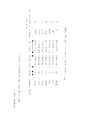
LPF54は例えば27タップのFIRフィルタとされ、係数は以下のとおりである。
By passing the demodulated signal demod out through the
The
-0.000640711
-0.000865006
0.001989255
0.009348803
0.020221675
0.03125
0.040826474
0.050034929
0.05852149
0.065960023
0.072064669
0.076600831
0.079394185
0.080337385 ;Center
0.079394185
0.076600831
0.072064669
0.065960023
0.05852149
0.050034929
0.040826474
0.03125
0.020221675
0.009348803
0.001989255
-0.000865006
-0.000640711
-0.000640711
-0.000865006
0.001989255
0.009348803
0.020221675
0.03125
0.040826474
0.050034929
0.05852149
0.065960023
0.072064669
0.076600831
0.079394185
0.080337385; Center
0.079394185
0.076600831
0.072064669
0.065960023
0.05852149
0.050034929
0.040826474
0.03125
0.020221675
0.009348803
0.001989255
-0.000865006
-0.000640711
このようなLPF54から得られたLPF out信号をコンパレータとして形成されるスライサ55で2値化することで、図24(g)の復調データ(demod data)が得られる。
この2値化された出力である復調データ(demod data)はアドレス情報を形成するチャンネルビットデータとなり、図22に示したアドレスデコーダ9に供給されて、ADIPアドレスがデコードされるものとなる。
The LPF out signal obtained from such an
The demodulated data (demod data), which is binarized output, becomes channel bit data forming address information, and is supplied to the
3.ディスク製造方法
続いて、上述した本例のディスクを製造方法を説明する。
ディスクの製造プロセスは、大別すると、いわゆる原盤工程(マスタリングプロセス)と、ディスク化工程(レプリケーションプロセス)に分けられる。原盤工程はディスク化工程で用いる金属原盤(スタンパー)を完成するまでのプロセスであり、ディスク化工程はスタンパーを用いて、その複製である光ディスクを大量生産するプロセスである。
3. Disc Manufacturing Method Next, a method for manufacturing the above-described disc of this example will be described.
The disc manufacturing process is roughly divided into a so-called master process (mastering process) and a disc forming process (replication process). The master process is a process until the completion of a metal master (stamper) used in the disc making process, and the disc making process is a process for mass-producing an optical disc as a duplicate using the stamper.
具体的には、原盤工程は、研磨した硝子基板にフォトレジストを塗布し、この感光膜にレーザビームによる露光によってピットやグルーブを形成する、いわゆるカッティングを行なう。
本例の場合、ディスクの最内周側のPBゾーンに相当する部分でプリレコーデッド情報に基づいたウォブリングによるグルーブのカッティングが行われ、またRWゾーンに相当する部分で、ADIPアドレスに基づいたウォブリングによるグルーブのカッティングが行われる。
Specifically, in the master process, so-called cutting is performed in which a photoresist is applied to a polished glass substrate, and pits and grooves are formed on the photosensitive film by exposure with a laser beam.
In the case of this example, groove cutting by wobbling based on pre-recorded information is performed in the portion corresponding to the PB zone on the innermost circumference side of the disk, and wobbling based on the ADIP address in the portion corresponding to the RW zone. Groove cutting is performed.
記録するプリレコーデッド情報はプリマスタリングと呼ばれる準備工程で用意される。
そしてカッティングが終了すると、現像等の所定の処理を行なった後、例えば電鋳によって金属表面上への情報の転送を行ない、ディスクの複製を行なう際に必要なスタンパーを作成する。
次に、このスタンパーを用いて例えばインジェクション法等によって、樹脂基板上に情報を転写し、その上に反射膜を生成した後、必要なディスク形態に加工する等の処理を行なって、最終製品を完成する。
The prerecorded information to be recorded is prepared in a preparation process called premastering.
When the cutting is completed, after performing a predetermined process such as development, information is transferred onto the metal surface by, for example, electroforming, and a stamper necessary for copying the disk is created.
Next, using this stamper, the information is transferred onto a resin substrate by, for example, an injection method, and after a reflective film is formed thereon, processing such as processing into a required disk form is performed to obtain a final product. Complete.
カッティング装置は、例えば図25に示すように、プリレコーデッド情報発生部71,アドレス発生部72、切換部73、カッティング部74、コントローラ70を備える。
プリレコーデッド情報発生部71は、プリマスタリング工程で用意されたプリレコーデッド情報を出力する。
アドレス発生部72は、絶対アドレスとしての値を順次出力する。
For example, as shown in FIG. 25, the cutting apparatus includes a prerecorded
The prerecorded
The
カッティング部74は、フォトレジストされた硝子基板101にレーザービームを照射してカッティングを行なう光学部(82,83,84)と、硝子基板101を回転駆動及びスライド移送する基板回転/移送部85と、入力データを記録データに変換して光学部に供給する信号処理部81と、基板回転/移送部85の位置から、カッティング位置がPBゾーンとRWゾーンのいずれであるかを判別できるようにしたセンサ86を有する。
The cutting unit 74 includes an optical unit (82, 83, 84) that performs cutting by irradiating a laser beam onto the
上記光学部としては、例えばHe−Cdレーザからなるレーザ光源82と、このレーザ光源82からの出射光を記録データに基づいて変調する変調部83と、変調部83からの変調ビームを集光して硝子基板101のフォトレジスト面に照射するカッティングヘッド部84が設けられている。
変調部83としてはレーザ光源82からの出射光をオン/オフする音響光学型の光変調器(AOM)と、さらにレーザ光源82からの出射光をウォブル生成信号に基づいて偏向する音響光学型の光偏向器(AOD)が設けられる。
The optical unit includes, for example, a
The modulating
また、基板回転/移送部85は、硝子基板101を回転駆動する回転モータと、回転モータの回転速度を検出する検出部(FG)と、硝子基板101をその半径方向にスライドさせるためのスライドモータと、回転モータ、スライドモータの回転速度や、カッティングヘッド部84のトラッキング等を制御するサーボコントローラなどを有して構成される。
The substrate rotation /
信号処理部81は、例えば切換部73を介して供給されるプリレコーデッド情報やアドレス情報に対して、例えばエラー訂正符号等を付加して入力データを形成するフォーマティング処理や、フォーマティング処理データに所定の演算処理を施して変調信号を形成する変調信号生成処理を行う。
そして変調信号に基づいて変調部83の光変調器及び光偏向器を駆動する駆動処理も行う。
For example, the
Based on the modulation signal, drive processing for driving the optical modulator and the optical deflector of the
カッティング部74では、カッティングの際、基板回転/移送部85が硝子基板101を一定線速度で回転駆動するとともに、硝子基板71を回転させたまま、所定のトラックピッチでらせん状のトラックが形成されていくようにスライドさせる。
同時に、レーザ光源82からの出射光は変調部83を介して、信号処理部81からの変調信号に基づく変調ビームとされてカッティングヘッド部84から硝子基板71のフォトレジスト面に照射されていき、その結果、フォトレジストがデータやグルーブに基づいて感光される。
In the cutting unit 74, when cutting, the substrate rotation /
At the same time, the light emitted from the
コントローラ70は、このようなカッティング部74のカッティング時の動作を実行制御するとともに、センサ86からの信号を監視しながらプリレコーデッド情報発生部71、アドレス発生部72、切換部73を制御する。
コントローラ70は、カッティング開始時には、カッティング部74に対してカッティングヘッド部84が最内周側からレーザ照射を開始するように、基板回転/移送部85のスライド位置を初期位置とさせる。そして硝子基板101のCLV回転駆動と、トラックピッチ0.35μmのグルーブを形成するためのスライド移送を開始させる。
この状態で、プリレコーデッド情報発生部71からプリレコーデッド情報を出力させ、切換部73を介して信号処理部81に供給させる。また、レーザ光源82からのレーザ出力を開始させ、変調部83は信号処理部81からの変調信号、即ちプリレコーデッド情報のFMコード変調信号に基づいてレーザ光を変調させ、硝子基板101へのグルーブカッティングを実行させる。
これにより、PBゾーンに相当する領域に、上述した図3(b)のようなグルーブのカッティングが行われていく。
The
At the start of cutting, the
In this state, pre-recorded information is output from the pre-recorded
As a result, the groove cutting as shown in FIG. 3B described above is performed in the region corresponding to the PB zone.
その後、コントローラ70はセンサ86の信号から、カッティング動作がPBゾーンに相当する位置まで進んだことを検出したら、切換部73をアドレス発生部72側に切り換えると共に、アドレス発生部72からアドレス値を順次発生させるように指示する。
また基板回転/移送部85には、トラックピッチ0.32μmのグルーブを形成するようにスライド移送速度を低下させる。
Thereafter, when the
In addition, the slide transfer speed is reduced in the substrate rotation /
これによりアドレス発生部72からアドレス情報が切換部73を介して信号処理部81に供給される。そして、レーザ光源82からのレーザ光は変調部83において信号処理部81からの変調信号、即ちアドレス情報のMSK変調信号に基づいて変調され、その変調レーザ光により硝子基板101へのグルーブカッティングが実行される。
これにより、RWゾーンに相当する領域に、上述した図3(a)のようなグルーブのカッティングが行われていく。
コントローラ70はセンサ86の信号から、当該カッティング動作がリードアウトゾーンの終端に達したことを検出したら、カッティング動作を終了させる。
As a result, the address information is supplied from the
As a result, the groove cutting as shown in FIG. 3A described above is performed in the region corresponding to the RW zone.
When the
このような動作により、硝子基板101上にPBゾーン及びRWゾーンとしてのウォブリンググルーブに対応する露光部が形成されていく。
その後、現像、電鋳等を行ないスタンパーが生成され、スタンパーを用いて上述のディスクが生産される。
By such an operation, exposure portions corresponding to the wobbling grooves as the PB zone and the RW zone are formed on the
Thereafter, development, electroforming, and the like are performed to produce a stamper, and the above-described disk is produced using the stamper.
以上、実施の形態のディスク及びそれに対応するディスクドライブ装置、ディスク製造方法について説明してきたが、本発明はこれらの例に限定されるものではなく、要旨の範囲内で各種変形例が考えられるものである。 The disk of the embodiment, the disk drive device corresponding to the disk, and the disk manufacturing method have been described above, but the present invention is not limited to these examples, and various modifications can be considered within the scope of the gist. It is.
1 ピックアップ、2 スピンドルモータ、3 スレッド機構、4 マトリクス回路、5 リーダ/ライタ回路、6 変復調回路、7 ECCエンコーダ/デコーダ、8 ウォブル回路、9 アドレスデコーダ、10 システムコントローラ、11 サーボ回路、12 スピンドルサーボ回路、13 レーザドライバ、20 AVシステム、51,52 バンドパスフィルタ、53 乗算器、54 ローパスフィルタ、55 スライサ、70 コントローラ、71 プリレコーデッド情報発生部、72 アドレス発生部、73 切換部、74 カッティング部、100 ディスク 1 pickup, 2 spindle motor, 3 thread mechanism, 4 matrix circuit, 5 reader / writer circuit, 6 modulation / demodulation circuit, 7 ECC encoder / decoder, 8 wobble circuit, 9 address decoder, 10 system controller, 11 servo circuit, 12 spindle servo Circuit, 13 Laser driver, 20 AV system, 51, 52 Band pass filter, 53 Multiplier, 54 Low pass filter, 55 Slicer, 70 Controller, 71 Pre-recorded information generating unit, 72 Address generating unit, 73 Switching unit, 74 Cutting Part, 100 discs
Claims (13)
上記グルーブのウォブリングによってアドレス情報が記録されると共に、当該グルーブによって形成されるトラックが記録マーク情報の記録再生に用いられる記録再生領域と、
上記グルーブのウォブリングによってプリレコーデッド情報が記録される再生専用領域と、
を有し、
上記プリレコーデッド情報のECCブロックは第1の数のフレーム単位に分割され、
上記再生専用領域のフレームシンクとして、上記第1の数よりも少ない第2の数の種類のフレームシンクを用い、上記第1の数のフレームに、上記フレームシンクの種類を、決められた順番に配置された
ディスク記録媒体。 Grooves for forming tracks on the disk are formed in a spiral shape,
Address information is recorded by wobbling of the groove, and a recording / reproducing area in which a track formed by the groove is used for recording / reproducing the recording mark information;
A read-only area where prerecorded information is recorded by wobbling the groove,
Have
The ECC block of the prerecorded information is divided into a first number of frame units,
A second number of types of frame syncs smaller than the first number are used as frame syncs in the read-only area, and the types of the frame syncs are determined in a predetermined order for the first number of frames. Disc recording medium arranged .
上記第2の数の種類のフレームシンクは、7種類のフレームシンクFS0、FS1、FS2、FS3、FS4、FS5、FS6であり、The second number of types of frame syncs are seven types of frame syncs FS0, FS1, FS2, FS3, FS4, FS5, and FS6.
上記第1の数のフレームの最初のフレームには上記FS0を配置され、上記最初のフレーム以外のフレームには上記FS1、FS2、FS3、FS4、FS5、FS6のいずれかを配置されたThe FS0 is arranged in the first frame of the first number of frames, and any one of the FS1, FS2, FS3, FS4, FS5, FS6 is arranged in a frame other than the first frame.
記録媒体。recoding media.
上記最初のフレーム以外のフレームに配置された上記フレームシンクの種類の決められた順番は、FS1、FS2、FS3、FS3、FS1、FS4、FS1、FS5、FS5、FS4、FS3、FS4、FS6、FS6、FS3、FS5、FS3、FS2、FS2、FS5、FS6、FS5、FS1、FS1、FS6、FS2、FS6、FS4、FS4、FS2、である
ディスク記録媒体。 The disc recording medium according to claim 2,
The determined order of the types of the frame syncs arranged in the frames other than the first frame is FS1, FS2, FS3, FS3, FS1, FS4, FS1, FS5, FS5, FS4, FS3, FS4, FS6, FS6. , FS3, FS5, FS3, FS2, FS2, FS5, FS6, FS5, FS1, FS1, FS6, FS2, FS6, FS4, FS4, FS2.
Disc recording medium.
上記配置されたFS1、FS2、FS3、FS4、FS5、FS6の並ぶ順番によりアドレスを特定されるThe address is specified by the order in which the FS1, FS2, FS3, FS4, FS5, and FS6 are arranged.
ディスク記録媒体。Disc recording medium.
上記トラックに対してレーザ照射を行い反射光信号を得るヘッド手段と、
上記反射光信号からトラックのウォブリングに係る信号を抽出するウォブリング抽出手段と、
上記反射光信号から記録マーク情報に係る信号を抽出する記録マーク情報抽出手段と、
上記記録再生領域の再生時において、上記ウォブリング抽出手段によって抽出された上記ウォブリングに係る信号についてMSK復調を行い、上記アドレス情報をデコードするアドレスデコード手段と、
上記記録再生領域の再生時において、上記記録マーク情報抽出手段によって抽出された上記記録マーク情報に係る信号についてデコード処理を行い、記録マーク情報として記録された情報を得る記録マークデコード手段と、
上記再生専用領域の再生時において、上記ウォブリング抽出手段によって抽出された上記ウォブリングに係る信号についてデコードを行い、上記プリレコーデッド情報を得るプリレコーデッド情報デコード手段と、
を備えるディスクドライブ装置。 Grooves for forming tracks on a disk are formed in a spiral shape, and address information is recorded by wobbling the grooves, and the tracks formed by the grooves are used for recording / reproduction of recording mark information. A read-only area in which pre-recorded information is recorded by wobbling the groove, and the ECC block of the pre-recorded information is divided into a first number of frames, A second number of types of frame syncs smaller than the first number are used as frame syncs, and the types of frame syncs are arranged in a predetermined order in the first number of frames. A disk drive device for recording or reproducing data on a medium,
Head means for irradiating the track with laser to obtain a reflected light signal;
Wobbling extraction means for extracting a signal related to wobbling of the track from the reflected light signal;
Recording mark information extracting means for extracting a signal related to recording mark information from the reflected light signal;
Address decoding means for performing MSK demodulation on the signal related to the wobbling extracted by the wobbling extracting means and decoding the address information at the time of reproducing the recording / reproducing area;
Recording mark decoding means for performing decoding processing on the signal related to the recording mark information extracted by the recording mark information extracting means at the time of reproduction of the recording / reproducing area, and obtaining information recorded as recording mark information;
Pre-recorded information decoding means for decoding the signal related to the wobbling extracted by the wobbling extracting means at the time of reproduction of the read-only area and obtaining the pre-recorded information;
Ru equipped with a disk drive unit.
上記ディスク記録媒体は、上記第2の数の種類のフレームシンクは、7種類のフレームシンクFS0、FS1、FS2、FS3、FS4、FS5、FS6であり、上記第1の数のフレームの最初のフレームには上記FS0を配置され、上記最初のフレーム以外のフレームには上記FS1、FS2、FS3、FS4、FS5、FS6のいずれかを配置された請求項5に記載のディスクドライブ装置。In the disk recording medium, the second number of types of frame syncs are seven types of frame syncs FS0, FS1, FS2, FS3, FS4, FS5, FS6, and the first frame of the first number of frames. 6. The disk drive device according to claim 5, wherein the FS0 is arranged, and any one of the FS1, FS2, FS3, FS4, FS5, and FS6 is arranged in a frame other than the first frame.
上記記録再生領域の再生時には、
トラックに対してレーザ照射を行った際の反射光信号から、トラックのウォブリングに係る信号、及び記録マーク情報に係る信号を抽出し、抽出された上記ウォブリングに係る信号についてMSK復調を行って上記アドレス情報をデコードするとともに、抽出された上記記録マーク情報に係る信号についてデコード処理を行って記録マーク情報として記録された情報を得、
上記再生専用領域の再生時には、
トラックに対してレーザ照射を行った際の反射光信号から、トラックのウォブリングに係る信号を抽出し、抽出された上記ウォブリングに係る信号についてデコードを行い、上記プリレコーデッド情報を得る
再生方法。 Grooves for forming tracks on a disk are formed in a spiral shape, and address information is recorded by wobbling the grooves, and the tracks formed by the grooves are used for recording / reproduction of recording mark information. A read-only area in which pre-recorded information is recorded by wobbling the groove, and the ECC block of the pre-recorded information is divided into a first number of frames, A second number of types of frame syncs smaller than the first number are used as frame syncs, and the types of frame syncs are arranged in a predetermined order in the first number of frames. As a playback method for media,
When playing back the recording / playback area,
A signal related to the wobbling of the track and a signal related to the recording mark information are extracted from the reflected light signal when the track is irradiated with the laser, and the above-mentioned address related to the wobbling is subjected to MSK demodulation to perform the above addressing. While decoding information, it performs decoding processing on the signal related to the extracted recording mark information to obtain information recorded as recording mark information,
During playback of the playback-only area,
A reproduction method for extracting pre-recorded information by extracting a signal related to wobbling of a track from a reflected light signal when a track is irradiated with laser, and decoding the extracted signal related to wobbling.
再生専用領域のグルーブをプリレコーデッド情報に基づいてウォブリングさせたグルーブとして形成し、
記録再生領域のグルーブを、アドレス情報に基づいてウォブリングさせたグルーブとして形成していくことで、当該グルーブによって形成されるトラックが記録マーク情報の記録再生に用いられるように形成し、
上記プリレコーデッド情報のウォブリングは、第1の数のフレーム単位に分割され、上記再生専用領域のフレームシンクとして、上記第1の数よりも少ない第2の数の種類のフレームシンクを用い、上記第1の数のフレームに、上記フレームシンクの種類を、決められた順番に配置するようにした
ディスク製造方法。 A spiral groove is formed on the disk to form tracks.
The groove of the playback-only area is formed as a groove wobbled based on the prerecorded information,
By forming the groove in the recording / reproducing area as a groove wobbled based on the address information, the track formed by the groove is formed to be used for recording / reproducing the recording mark information,
The wobbling of the pre-recorded information is divided into a first number of frames, and a second number of types of frame syncs smaller than the first number are used as frame syncs of the read-only area, A disc manufacturing method in which the types of frame syncs are arranged in a predetermined order in a first number of frames .
Priority Applications (1)
| Application Number | Priority Date | Filing Date | Title |
|---|---|---|---|
| JP2008193917A JP4577427B2 (en) | 2008-07-28 | 2008-07-28 | DISC RECORDING MEDIUM, DISC DRIVE DEVICE, REPRODUCTION METHOD, AND DISC MANUFACTURING METHOD |
Applications Claiming Priority (1)
| Application Number | Priority Date | Filing Date | Title |
|---|---|---|---|
| JP2008193917A JP4577427B2 (en) | 2008-07-28 | 2008-07-28 | DISC RECORDING MEDIUM, DISC DRIVE DEVICE, REPRODUCTION METHOD, AND DISC MANUFACTURING METHOD |
Related Parent Applications (1)
| Application Number | Title | Priority Date | Filing Date |
|---|---|---|---|
| JP2001311489A Division JP4300727B2 (en) | 2001-10-09 | 2001-10-09 | DISC RECORDING MEDIUM, DISC DRIVE DEVICE, REPRODUCTION METHOD, AND DISC MANUFACTURING METHOD |
Related Child Applications (1)
| Application Number | Title | Priority Date | Filing Date |
|---|---|---|---|
| JP2010113044A Division JP5184577B2 (en) | 2010-05-17 | 2010-05-17 | Disc recording medium, disc drive apparatus, and playback method |
Publications (2)
| Publication Number | Publication Date |
|---|---|
| JP2008287879A JP2008287879A (en) | 2008-11-27 |
| JP4577427B2 true JP4577427B2 (en) | 2010-11-10 |
Family
ID=40147440
Family Applications (1)
| Application Number | Title | Priority Date | Filing Date |
|---|---|---|---|
| JP2008193917A Expired - Lifetime JP4577427B2 (en) | 2008-07-28 | 2008-07-28 | DISC RECORDING MEDIUM, DISC DRIVE DEVICE, REPRODUCTION METHOD, AND DISC MANUFACTURING METHOD |
Country Status (1)
| Country | Link |
|---|---|
| JP (1) | JP4577427B2 (en) |
Citations (2)
| Publication number | Priority date | Publication date | Assignee | Title |
|---|---|---|---|---|
| JP2001167446A (en) * | 1999-11-03 | 2001-06-22 | Samsung Electronics Co Ltd | Pid addressing method using wobble signal, wobble address encoding circuit, its detecting method and circuit, and recording medium |
| JP4300727B2 (en) * | 2001-10-09 | 2009-07-22 | ソニー株式会社 | DISC RECORDING MEDIUM, DISC DRIVE DEVICE, REPRODUCTION METHOD, AND DISC MANUFACTURING METHOD |
Family Cites Families (6)
| Publication number | Priority date | Publication date | Assignee | Title |
|---|---|---|---|---|
| NL8701632A (en) * | 1987-07-10 | 1989-02-01 | Philips Nv | SYSTEM FOR RECORDING AND / OR READING AN INFORMATION SIGNAL, A RECORD CARRIER, A RECORDING AND / OR READING DEVICE FOR USE IN SUCH A SYSTEM, AND AN APPARATUS AND METHOD FOR MANUFACTURING SUCH RECORD CARRIER. |
| JPH0250361A (en) * | 1988-08-12 | 1990-02-20 | Sharp Corp | Pcm recording and reproducing device |
| JP3917207B2 (en) * | 1996-01-12 | 2007-05-23 | パイオニア株式会社 | Pre-information recording method and apparatus, information recording method and apparatus, and information recording medium |
| JP3845951B2 (en) * | 1997-05-23 | 2006-11-15 | ソニー株式会社 | Disc-shaped recording medium, disc reproducing apparatus, and disc reproducing method |
| JPH11134671A (en) * | 1997-10-28 | 1999-05-21 | Sony Corp | Reproducing device and method thereof |
| JPH11149644A (en) * | 1997-11-18 | 1999-06-02 | Sony Corp | Optical disk, optical disk record device, its method, optical disk recording and reproducing device and its method |
-
2008
- 2008-07-28 JP JP2008193917A patent/JP4577427B2/en not_active Expired - Lifetime
Patent Citations (2)
| Publication number | Priority date | Publication date | Assignee | Title |
|---|---|---|---|---|
| JP2001167446A (en) * | 1999-11-03 | 2001-06-22 | Samsung Electronics Co Ltd | Pid addressing method using wobble signal, wobble address encoding circuit, its detecting method and circuit, and recording medium |
| JP4300727B2 (en) * | 2001-10-09 | 2009-07-22 | ソニー株式会社 | DISC RECORDING MEDIUM, DISC DRIVE DEVICE, REPRODUCTION METHOD, AND DISC MANUFACTURING METHOD |
Also Published As
| Publication number | Publication date |
|---|---|
| JP2008287879A (en) | 2008-11-27 |
Similar Documents
| Publication | Publication Date | Title |
|---|---|---|
| JP4652641B2 (en) | Disc recording medium, disc drive apparatus, and playback method | |
| US8064301B2 (en) | Disk recording medium, disk drive apparatus, reproduction method, and disk manufacturing method | |
| JP4115173B2 (en) | Disc recording medium, disc manufacturing method, disc drive apparatus | |
| JP4577427B2 (en) | DISC RECORDING MEDIUM, DISC DRIVE DEVICE, REPRODUCTION METHOD, AND DISC MANUFACTURING METHOD | |
| JP5184577B2 (en) | Disc recording medium, disc drive apparatus, and playback method | |
| JP5267724B2 (en) | Disc recording medium, disc drive apparatus, and playback method | |
| JP4192953B2 (en) | Disc recording medium, disc manufacturing method, disc drive apparatus | |
| JP4993013B2 (en) | Disc recording medium, recording method, recording apparatus, reproducing method, and reproducing apparatus | |
| JP4905423B2 (en) | Disc recording medium, disc drive apparatus, and playback method | |
| JP4192941B2 (en) | Recording medium, recording apparatus, and recording method | |
| JP5494713B2 (en) | Disc recording medium, recording method, disc drive apparatus, and reproducing method | |
| JP5204829B2 (en) | Disc recording medium, reproducing method and reproducing apparatus | |
| JP5001337B2 (en) | Recording method and recording apparatus |
Legal Events
| Date | Code | Title | Description |
|---|---|---|---|
| A521 | Request for written amendment filed |
Free format text: JAPANESE INTERMEDIATE CODE: A523 Effective date: 20080827 |
|
| A621 | Written request for application examination |
Free format text: JAPANESE INTERMEDIATE CODE: A621 Effective date: 20080827 |
|
| A977 | Report on retrieval |
Free format text: JAPANESE INTERMEDIATE CODE: A971007 Effective date: 20100208 |
|
| A131 | Notification of reasons for refusal |
Free format text: JAPANESE INTERMEDIATE CODE: A131 Effective date: 20100316 |
|
| A521 | Request for written amendment filed |
Free format text: JAPANESE INTERMEDIATE CODE: A523 Effective date: 20100517 |
|
| TRDD | Decision of grant or rejection written | ||
| A01 | Written decision to grant a patent or to grant a registration (utility model) |
Free format text: JAPANESE INTERMEDIATE CODE: A01 Effective date: 20100727 |
|
| A01 | Written decision to grant a patent or to grant a registration (utility model) |
Free format text: JAPANESE INTERMEDIATE CODE: A01 |
|
| A61 | First payment of annual fees (during grant procedure) |
Free format text: JAPANESE INTERMEDIATE CODE: A61 Effective date: 20100809 |
|
| FPAY | Renewal fee payment (event date is renewal date of database) |
Free format text: PAYMENT UNTIL: 20130903 Year of fee payment: 3 |
|
| R151 | Written notification of patent or utility model registration |
Ref document number: 4577427 Country of ref document: JP Free format text: JAPANESE INTERMEDIATE CODE: R151 |
|
| FPAY | Renewal fee payment (event date is renewal date of database) |
Free format text: PAYMENT UNTIL: 20130903 Year of fee payment: 3 |
|
| R250 | Receipt of annual fees |
Free format text: JAPANESE INTERMEDIATE CODE: R250 |
|
| R250 | Receipt of annual fees |
Free format text: JAPANESE INTERMEDIATE CODE: R250 |
|
| R250 | Receipt of annual fees |
Free format text: JAPANESE INTERMEDIATE CODE: R250 |
|
| R250 | Receipt of annual fees |
Free format text: JAPANESE INTERMEDIATE CODE: R250 |
|
| R250 | Receipt of annual fees |
Free format text: JAPANESE INTERMEDIATE CODE: R250 |
|
| R250 | Receipt of annual fees |
Free format text: JAPANESE INTERMEDIATE CODE: R250 |
|
| R250 | Receipt of annual fees |
Free format text: JAPANESE INTERMEDIATE CODE: R250 |
|
| R250 | Receipt of annual fees |
Free format text: JAPANESE INTERMEDIATE CODE: R250 |