JP4574923B2 - Method and apparatus for reducing frame error rate - Google Patents
Method and apparatus for reducing frame error rate Download PDFInfo
- Publication number
- JP4574923B2 JP4574923B2 JP2001512719A JP2001512719A JP4574923B2 JP 4574923 B2 JP4574923 B2 JP 4574923B2 JP 2001512719 A JP2001512719 A JP 2001512719A JP 2001512719 A JP2001512719 A JP 2001512719A JP 4574923 B2 JP4574923 B2 JP 4574923B2
- Authority
- JP
- Japan
- Prior art keywords
- signal
- signal quality
- quality measurement
- demodulated
- power
- Prior art date
- Legal status (The legal status is an assumption and is not a legal conclusion. Google has not performed a legal analysis and makes no representation as to the accuracy of the status listed.)
- Expired - Fee Related
Links
Images


Classifications
-
- H—ELECTRICITY
- H04—ELECTRIC COMMUNICATION TECHNIQUE
- H04W—WIRELESS COMMUNICATION NETWORKS
- H04W52/00—Power management, e.g. TPC [Transmission Power Control], power saving or power classes
- H04W52/04—TPC
- H04W52/18—TPC being performed according to specific parameters
-
- H—ELECTRICITY
- H04—ELECTRIC COMMUNICATION TECHNIQUE
- H04B—TRANSMISSION
- H04B7/00—Radio transmission systems, i.e. using radiation field
- H04B7/14—Relay systems
- H04B7/15—Active relay systems
- H04B7/185—Space-based or airborne stations; Stations for satellite systems
- H04B7/1853—Satellite systems for providing telephony service to a mobile station, i.e. mobile satellite service
- H04B7/18539—Arrangements for managing radio, resources, i.e. for establishing or releasing a connection
- H04B7/18543—Arrangements for managing radio, resources, i.e. for establishing or releasing a connection for adaptation of transmission parameters, e.g. power control
-
- H—ELECTRICITY
- H04—ELECTRIC COMMUNICATION TECHNIQUE
- H04W—WIRELESS COMMUNICATION NETWORKS
- H04W28/00—Network traffic management; Network resource management
- H04W28/02—Traffic management, e.g. flow control or congestion control
- H04W28/04—Error control
-
- H—ELECTRICITY
- H04—ELECTRIC COMMUNICATION TECHNIQUE
- H04W—WIRELESS COMMUNICATION NETWORKS
- H04W52/00—Power management, e.g. TPC [Transmission Power Control], power saving or power classes
- H04W52/04—TPC
- H04W52/18—TPC being performed according to specific parameters
- H04W52/20—TPC being performed according to specific parameters using error rate
Landscapes
- Engineering & Computer Science (AREA)
- Computer Networks & Wireless Communication (AREA)
- Signal Processing (AREA)
- Physics & Mathematics (AREA)
- Astronomy & Astrophysics (AREA)
- Aviation & Aerospace Engineering (AREA)
- General Physics & Mathematics (AREA)
- Mobile Radio Communication Systems (AREA)
- Detection And Prevention Of Errors In Transmission (AREA)
Description
【0001】
【発明の属する技術分野】
本発明は無線通信システム、特に無線通信システムのフレームエラー率(FER)を減少させる方法および装置に関する。
【0002】
【従来の技術】
(例えば1%よりも大きい)比較的貧弱なFERを有する無線リンクによってデータを転送するとき、データサービスが要求している程度に低いFERを実現するためにデータを再送信する多数の方法が存在する。例えば循環冗長符号チェック方式(CRC)はデータのブロックの完全性をチェックするためにリンクの受信端部で実行されることができる。CRCはデータ通信でそのデータが正確に受信されたことを設定するよく知られた方法である。CRC符号は送信装置で発生されデータブロックに添付される。受信端部は類似の計算を行い、その結果を付加されたCRC符号と比較する。違いが存在するならば、受信端部はデータブロックの再送信をリクエストする。
【0003】
例えば自動再送信リクエスト(ARQ)のようなプロトコルの使用はデータブロックの再送信に使用されることができる。ARQでは、送信装置はデータブロックに基づいてエラー検出フィールド(例えばCRCフィールド)を符号化する。受信端部がチェックフィールドを再度計算し、これを受信されたものと比較する。これらが一致するとき、確認(ACK)が送信装置へ返送される。これらが一致しないならば、否定的確認(NAK)が返信され、送信装置はメッセージを再度送信する。
【0004】
【発明が解決しようとする課題】
前述の方法は多数のタイプのデータの送信に対して満足できるものである。しかしながら、低いFERを実現する方法はデータブロックの再送信により待ち時間を増加させる。このような増加された待ち時間は、実時間デジタル化音声または他のタイプの待ち時間に敏感なデータのようなあるタイプのデータを送信するときには許容されることができない。特に、データブロックの再送信は遅延時間を生じ、その遅延時間は平均して高く、また多数の待ち時間に敏感なシステムでは要求よりも大きな変化がある。
【0005】
待ち時間を増加せずに低いFERを有するデータを転送する方法および装置が必要とされている、換言すると、データブロックの再送信に依存せずにFERを減少する方法および装置が必要とされている。
【0006】
【課題を解決するための手段】
本発明は、信号送信パワーを制御するための方法および装置に関する。本発明の方法は、受信された信号を復調して復調された信号を発生し、復調された信号を歪ませて歪まされた復調された信号を発生するステップを含んでいる。復調された信号は例えば雑音を付加することによって歪まされることができる。信号対雑音比のような信号品質の測定は、復調された信号ではなく歪まされた復調された信号に基づいて決定される。送信パワーの調節は歪まされた復調された信号の信号品質測定結果に基づいてリクエストされる。
【0007】
本発明の1実施形態では、決定された信号品質測定値はしきい値と比較され、送信パワーの調節は比較結果に基づいてリクエストされる。しきい値は信号が受信されるべき所望の最小の信号品質レベルを表す。SNRのような幾つかの品質測定関数は信号品質に比例する値を有する。即ち、これらは品質の増加によって増加し、品質の低下で減少する。それ故、これらの信号品質測定値がしきい値よりも下に落ちるならば、送信パワーの増加がリクエストされ、信号品質測定値がしきい値を超えるならば、送信パワーの減少がリクエストされる。他の関数はエラーイベントに基づいて、信号品質に反比例する値を有し、信号品質の増加により値が減少し、反対ならば逆になる。この状態では、測定値がしきい値よりも下に落ちるならば、送信パワーの減少がリクエストされ、測定値がしきい値を超えたならば、送信パワーの増加がリクエストされる。
【0008】
1実施形態では、本発明の方法はさらに復調された信号をデコードして決定データを発生し、歪まされた復調された信号を復号して歪まされた決定データを発生するステップを含んでいる。第2の信号品質測定値または“エラーイベント”の測定値は(決定データではなく)前記歪まされた決定データに基づいて決定される。送信パワーの増加または減少を決定するために使用されるしきい値は第2の信号品質測定値に基づいて調節される。
【0009】
信号が基地局により送信され、ユーザ端末により受信される1実施形態では、本発明のステップはユーザ端末により実行され、基地局の送信パワーが制御される。
信号が衛星を使用して、ゲートウェイにより送信されユーザ端末により受信される本発明の別の実施形態では、本発明のステップはユーザ端末によって実行され、ゲートウェイの送信パワーが制御される。
【0010】
信号がユーザ端末により送信され、基地局により受信されるさらに別の実施形態では、ユーザ端末の送信パワーが制御される。
信号が衛星を使用して、ユーザ端末により送信されゲートウェイにより受信される本発明のさらに別の実施形態では、本発明のステップはゲートウェイにより実行され、ユーザ端末の送信パワーが制御される。
【0011】
【発明の実施の形態】
本発明の特徴、目的、利点は図面を伴った以下の詳細な説明からさらに明白になるであろう。同一の参照符号は全体を通じて同一または類似の素子を示している。
本発明の好ましい実施形態を以下詳細に説明する。特別なステップ、構造、アレンジメントを説明するが、これは例示の目的でのみ行われることを理解すべきである。当業者はその他のステップ、構造、アレンジメントが本発明の技術的範囲を逸脱せずに使用されることができることを認識するであろう。
【0012】
I.環境例
本発明を詳細に説明する前に、本発明が実施されることができる例示的な環境を説明することが有効である。本発明は多数の無線通信システム、特に信号の送信に使用されるパワー量を制御するのに望ましいシステムで実行されることができる。このような環境は衛星、地上セルラ電話システムを含んでいるがそれらに限定されない。好ましい応用は移動体またはポータブル電話サービス用の符号分割多元アクセス(CDMA)無線拡散スペクトル通信システムにある。
【0013】
本発明は特に低地球軌道衛星を使用する通信システムにおける使用に適している。しかしながら、当業者に明白なように、本発明の概念は他のタイプの衛星および地上通信システムにも適用可能である。
【0014】
典型的に衛星ベースの通信システムはゲートウェイと、ゲートウェイと1以上のユーザ端末間で通信信号を中継するための1以上の衛星とを使用する。ゲートウェイは各ユーザ端末から他のユーザ端末または公共電話交換網のような他の接続された通信システムのユーザへ通信リンクを与える。典型的な地上システムは信号の送信と、ユーザ端末からの信号の受信に基地局を使用する。ユーザ端末は固定されているか、移動体電話のように可動である。
【0015】
幾つかの衛星および地上通信システムは、米国特許第4,901,307 号明細書(発明の名称“Spread Spectrum Multiple Access Communication System Using Satellite or Terrestrial Repeaters ”、1990年2月13日)と、米国特許第5,691,974 号明細書(発明の名称“Method and Apparatus for Using Full Spectrum Transmitted Power in a Spread Spectrum Communication System for Tracking Individual Recipient Phase Time and Energy”、1997年11月25日)に記載されているように、符号分割多元アクセス(CDMA)拡散スペクトル信号を使用する。
【0016】
典型的な拡散スペクトル通信システムでは、1以上の予め選択された疑似雑音(PN)コードシーケンスは通信信号として送信するために搬送波信号を変調する前に、予め定められたスペクトル帯域にわたり情報信号を変調または“拡散”するために使用される。PNコード拡散、即ち技術でよく知られている拡散スペクトル送信方法はデータ信号よりも非常に大きい帯域幅を有する信号を送信のために発生する。基地局またはゲートウェイ−ユーザ通信リンクでは、PN拡散コードまたは2進シーケンスは異なる基地局またはゲートウェイまたは異なるビームにより送信される信号間と、マルチパス信号間の弁別に使用される。
【0017】
典型的なCDMA拡散スペクトルシステムでは、チャンネル化コードはセル内の異なるユーザを目的地とする信号間、または順方向リンク(即ち基地局またはゲートウェイからユーザ端末トランシーバへの信号路)上の衛星サブビーム内で送信されるユーザ信号間の弁別に使用される。各ユーザトランシーバは特有の“チャンネル化”直交コードを使用することによって順方向リンクに設けられるその固有の直交チャンネルを有する。これらのチャンネルで転送される信号は通常“トラフィック信号”と呼ばれる。付加的なチャンネルは“ページング”、“同期”およびシステムユーザへ送信されるその他の信号のために設けられている。ウォルシュ関数はウォルシュコードとしても知られているチャンネルかコードを構成するために通常使用される。
【0018】
前述の特許明細書に開示されているようなCDMA拡散スペクトル通信システムは順方向リンクユーザ端末通信用のコヒーレントな変調および復調の使用を考慮している。この方法を使用する通信システムでは、“パイロット信号”とも呼ばれている“パイロット”搬送波信号は順方向リンク信号用のコヒーレントな位相基準として使用される。即ち、データ変調を含まない信号はゲートウェイまたは基地局により基準としてカバー区域を通じて送信される。
【0019】
パイロット信号は初期システム同期を獲得し、ゲートウェイまたは基地局により送信される他の信号の時間、周波数、位相追跡を行うためにユーザ端末により使用される。パイロット信号搬送波の追跡から得られる位相情報は他のシステム信号またはトラフィック(データ)信号のコヒーレントな復調の搬送波位相基準として使用される。この技術は多数のトラフィック信号が位相基準として共通のパイロット信号を共有することを可能にし、廉価でさらに効率的な追跡機構を与える。1つのパイロット信号は典型的にCDMAチャンネルまたはサブビームと呼ばれる使用される各周波数の各ゲートウェイまたは基地局により送信され、その周波数においてそのゲートウェイまたは基地局から信号を受信する全てのユーザ端末により共有される。
【0020】
ゲートウェイおよび基地局はページングチャンネルで送信されるページング信号として知られている1以上の信号を使用して情報をユーザ端末へ送信できる。例えば、呼が特定の移動体電話へ発信されるとき、ゲートウェイはページング信号手段によって移動体電話に警告する。ページング信号は呼の存在、使用されるトラフィックチャンネルを示し、またユーザ端末特定メッセージと共にシステムのオーバーヘッド情報を分配するために使用される。通信システムは幾つかのページングチャンネルを有してもよい。同期信号はまた時間同期を容易にするために有効なシステム情報の転送にも使用されることができる。これらの全ての信号はパイロット信号と類似の方法で共有されたリソースとして作用する。
【0021】
ユーザ端末は逆方向リンク(即ちユーザ端末から基地局またはゲートウェイトランシーバへの信号路)によってアクセス信号を送信することによってページング信号メッセージに応答することができる。アクセス信号はまたユーザ端末が呼を発信したとき使用されることもできる。
【0022】
任意の通信システムのように、通信信号はユーザ端末により受信され、さらに処理するためにベースバンド周波数に下方変換される。一度下方変換されると、信号は特定のパイロット信号または受信された信号を検出し、関連するページング、同期およびトラフィック信号を検出するためにデジタル的に処理される。復調中、PN拡散コードは信号と、データを与えるために信号と相関されるチャンネル化コードとをデスプレッドするために与えられる。
【0023】
本発明が有効である例示的な無線通信システムは図1で示されている。この通信システムはCDMAタイプの通信信号を使用するが、これは本発明により必要とされない。図1で示されている通信システム100 の一部分では、1つの基地局112 、2つの衛星116 と118 、2つの関連するゲートウェイまたはハブ120 と122 は2つの遠隔ユーザ端末124 と126 との通信を行うために示されている。典型的に基地局と衛星/ゲートウェイは地上または衛星ベースとして呼ばれている別々の通信システムのコンポーネントであるが、これは必要なことではない。このようなシステムの基地局、ゲートウェイ、衛星の総数は所望のシステム容量および技術でよく理解されているその他の要因に依存している。
【0024】
ユーザ端末124 と126 はそれぞれセルラ電話、データトランシーバ、ページングまたは位置決定受信機のような無線通信装置を具備しているがそれらに限定されず、所望によって手持ち式またはビークルに取付けられることができる。図1では、ユーザ端末124 はビークルに取付けられた装置として示され、ユーザ端末126 は手持ち式移動体電話として示されている。しかしながら、本発明の考察は遠隔無線サービスが所望される固定した装置に適用可能であることも理解されるであろう。ユーザ端末は時には、嗜好に基づいて、加入者装置、移動局、移動体装置、または幾つかの通信システムでは単に“ユーザ”または“加入者”とも呼ばれる。
【0025】
通常、衛星116 と118 からのビームは予め規定されたパターンで異なる地理区域をカバーする。異なる周波数のビームはCDMAチャンネルまたは“サブビーム”とも呼ばれ、同一区域をオーバーラップするように導かれることができる。多数の衛星のビームカバー区域またはサービス区域、あるいは多数の基地局のアンテナパターンは通信システムの設計と、提供されるサービスのタイプと、空間ダイバーシティが実現されるか否かに基づいて、所定区域で完全にまたは部分的にオーバーラップするように設計されることが当業者により容易に理解されるであろう。
【0026】
種々のマルチ衛星通信システムは多数のユーザ端末にサービスするために低地球軌道(LEO)で8つの異なる軌道面を移動する48以上程度の衛星を使用する例示的なシステムで提案されている。しかしながら、当業者は本発明の考察が種々の衛星システムと、他の軌道距離およびコンステレーションを含むゲートウェイ構造にどのように適用可能であるかを容易に理解するであろう。同時に、本発明は種々の基地局構造の地上ベースのシステムにも同様に応用可能である。
【0027】
図1では、ユーザ端末124 および126 と基地局112 、または衛星116 および118 を通じてゲートウェイ120 と122 との間で行われる通信のための幾つかの可能な信号路が示されている。基地局とユーザ端末の通信リンクはライン130 と132 により示されている。衛星116 および118 とユーザ端末124 および126 との間の衛星とユーザ端末の通信リンクはライン140 、142 、144 により示されている。ゲートウェイ120 および122 と衛星116 と118 の間のゲートウェイと衛星の通信リンクはライン146 、148 、150 、152 により図示されている。これらの通信リンクはまた通信チャンネルとも呼ばれる。ゲートウェイ120 および122 と、基地局112 は1方向または2方向通信システムの一部分として、または単にメッセージまたはデータをユーザ端末124 と126 へ転送するために使用される。好ましい実施形態では、ゲートウェイ120 および122 と、基地局112 は2方向通信システムの一部分として使用される。
【0028】
ユーザ端末124 と126 で使用するための例示的なトランシーバ200 は図2で示されている。トランシーバ200 はアナログ受信機214 に転送される通信信号を受信するため少なくとも1つのアンテナ210 を使用し、アナログ受信機214 においてこれらの信号は下方変換され、増幅され、デジタル化される。デュプレクサ素子212 は同じアンテナが送信と受信の両機能を行うことを可能にするために使用されることができる。しかしながら幾つかのシステムは異なる送信および受信周波数で動作するため別々のアンテナを使用する。
【0029】
アナログ受信機214 により出力されるデジタル通信信号は少なくとも1つのデジタルデータ受信機216Aと少なくとも1つのサーチャ受信機218 へ転送される。付加的なデジタルデータ受信機216B−216Nは当業者に明白であるように、ユーザ端末の複雑度の許容可能なレベルに基づいて所望レベルの信号ダイバーシティを得るために使用されることができる。デジタルデータ受信機216A−216Nはユーザ端末へアドレスされる受信された信号をデスプレッドし相関するために使用される。
【0030】
少なくとも1つのユーザ端末制御プロセッサ220 はデジタルデータ受信機216A−216Nとサーチャ受信機218 へ結合される。制御プロセッサ220 は他の機能の中で、基本的な信号の処理、タイミング、パワーおよびハンドオフ制御または、調節、信号搬送波に使用される周波数の選択を行う。しばしば制御プロセッサ220 により実行される別の基本的な制御機能は通信信号波形の処理に使用されるPNコードシーケンスまたは直交機能の選択および操作である。制御プロセッサ220 による信号処理は相対的な信号強度の決定と、種々の関連する信号パラメータの計算を含むことができる。タイミングおよび周波数のような信号パラメータの計算は、測定における効率または速度の増加、または制御処理リソースの改良された割当を与えるために付加的または別々の専用回路の使用を含んでもよい。
【0031】
デジタルデータ受信機216A−216Nの出力はユーザ端末内のダイバーシティ結合装置およびデコーダ回路222 に結合されている。デジタルデータ受信機216A−216Nはデジタル化され符号化されたスピーチのような復調されたユーザデータをダイバーシティ結合装置およびデコーダ回路222 へ与える。ダイバーシティ結合装置およびデコーダ回路222 はデジタルデータ受信機216A−216Nからの異なる信号を結合し、それによって単一のユーザデータ信号を与える。ユーザデジタルベースバンド回路122 はまたユーザデータで復号およびエラー補正を実行する。
【0032】
ダイバーシティ結合装置およびデコーダ回路222 からの信号出力は、ユーザとインターフェースするためにデジタルベースバンド回路224 に提供される。ユーザデジタルベースバンド回路224 はユーザ端末との間の情報の転送に使用される処理および提供素子を具備している。即ち一時的または長期のデジタルメモリのような信号またはデータ記憶素子と、ディスプレイスクリーン、スピーカ、キーパッド端末、ハンドセットのような入力および出力装置と、A/D素子と、ボコーダと、他の音声およびアナログ信号処理素子等は、全て技術でよく知られた素子を使用してユーザ端末ベースバンド回路224 の部分を形成している。これらの幾つかの素子は制御プロセッサ220 の制御下で、またはそれと通信して動作することができる。
【0033】
音声またはその他のデータがユーザ端末で開始する出力メッセージまたは通信信号として準備されるとき、ユーザデジタルベースバンド回路224 は送信のための所望のデータの受信、記憶、処理およびその他の処理に使用される。ユーザデジタルベースバンド回路224 はこのデータを制御プロセッサ220 の制御下で動作している送信変調器226 へ提供する。送信変調器226 の出力はパワー制御装置228 へ転送され、このパワー制御装置228 は出力パワー制御信号を送信パワー増幅器230 へ与え、出力信号をアンテナ210 からゲートウェイ120 、122 または基地局112 へ最終的に送信する。
【0034】
受信された通信信号の1以上の測定された信号パラメータまたは1以上の共有されたリソース信号に対応する情報またはデータは、技術で知られている種々の技術を使用してゲートウェイへ送信されることができる。例えば、情報は別々の情報信号として転送されるか、またはユーザデジタルベースバンド回路224 により処理されて他のメッセージへ添付されることができる。その代わりに情報は制御プロセッサ220 の制御下で送信変調器226 または送信パワー制御装置228 により予め定められた制御ビットとして挿入されることができる。
【0035】
デジタル受信機216A−216Nとサーチャ受信機218 は特別な信号の復調と追跡をするために信号相関素子で構成される。サーチャ受信機218 はパイロット信号または他の比較的固定したパターンの強力な信号のサーチに使用され、デジタル受信機216A−216Nは検出されたパイロット信号に関連する他の信号の復調に使用される。それ故、これらの装置の出力はパイロット信号または他の信号のエネルギまたは周波数を決定するために監視されることができる。これらの受信機はまた復調される信号の現在の周波数とタイミング情報を制御プロセッサ220 へ与えるために監視されることができる周波数追跡素子を使用する。
【0036】
デジタルデータ受信機216A−216N、ダイバーシティ結合装置およびデコーダ回路222 、デジタルベースバンド回路224 の付加的な詳細は本発明の実施形態にしたがって、図4および5の説明において後述する。
【0037】
ゲートウェイ120 と122 で使用する例示的な送信および受信装置300 は図3で示されている。図3に示されているゲートウェイ120 と122 の部分は技術でよく知られている種々の方式を使用して下方変換、増幅、デジタル化される通信信号を受信するためにアンテナ310 へ接続されている1以上のアナログ受信機314 を有している。多数のアンテナ310 は幾つかの通信システムで使用される。アナログ受信機314 により出力されるデジタル化された信号は324 の破線により示されているような、少なくとも1つのデジタル受信機モジュールへ入力として与えられる。
【0038】
ある変形が技術で知られているが、各デジタル受信機モジュール324 はゲートウェイ120 および122 と1つのユーザ端末124 および126 との間の通信を管理するために使用される信号処理素子に対応する。1つのアナログ受信機314 は多数のデジタル受信機モジュール324 の入力を与えることができ、このようなモジュールの数は全ての衛星ビームに適合するためにゲートウェイ120 と122 で使用され、可能なダイバーシティモード信号は任意の所定の時間に処理される。各デジタル受信機モジュール324 は1以上のデジタルデータ受信機316 とサーチャ受信機318 を有する。サーチャ受信機318 は通常パイロット信号以外の信号の適切なダイバーシティモードをサーチする。通信システムで実行する場合、多数のデジタルデータ受信機316A−316Nはダイバーシティ信号受信のために使用される。
【0039】
デジタルデータ受信機316 の出力はその後のベースバンド処理素子322 に与えられ、このベースバンド処理素子322 は技術でよく知られここでさらに詳細に説明されていない装置を具備している。例示的なベースバンド装置はマルチパス信号を各ユーザに対する1つの出力へ結合するためにダイバーシティ結合装置およびデコーダを含んでいる。例示的なベースバンド装置は出力データを典型的にデジタルスイッチまたはネットワークへ与えるためのインターフェース回路も含んでいる。ボコーダ、データモデム、デジタルデータスイッチング素子および記憶素子等の、しかしそれらに限定されない種々の他の既知の素子はベースバンド処理素子322 の一部を形成してもよい。これらの素子はデータ信号の1以上の送信モジュール334 への転送を制御または誘導するように動作する。
【0040】
ユーザ端末124 、126 へ送信される信号は1以上の適切な送信モジュール334 へそれぞれ結合される。典型的なゲートウェイ120 と122 は、一度に多数のユーザ端末124 と126 へサービスを提供し、一度に幾つかの衛星およびビームを与えるために複数のこのような送信モジュール334 を使用する。基地局112 はモデム構造で共にさらに緊密に送信および受信機能をグループ化する傾向があるが、基地局112 もまた複数のこのようなモジュールを使用してもよい。ゲートウェイ120 、122 により使用される送信モジュール334 数は、システムの複雑度、視野にある衛星数、システムユーザ容量、選択されるダイバーシティ度等を含む技術でよく知られた要因により決定される。
【0041】
各送信モジュール334 は送信用のデータを拡散スペクトル変調する送信変調器326 を含んでいる。送信変調器326 はデジタル送信パワー制御装置328 へ結合される出力を有し、デジタル送信パワー制御装置328 は出力されるデジタル信号で使用される送信パワーを制御する。デジタル送信パワー制御装置328 は干渉の減少とリソース割当の目的で最小レベルのパワーを供給するが、送信路および他の通路転送特性における減衰の補償が必要とされるとき適切なレベルのパワーを提供する。少なくとも1つのPN発生器332 は信号の拡散において送信変調器326 により使用される。このコード発生はまたゲートウェイ122 と124 で使用される1以上の制御プロセッサまたは記憶素子の機能部分を形成することができる。
【0042】
送信パワー制御装置328 の出力は合計装置336 に転送され、合計装置336 は他の送信パワー制御回路からの出力と合計される。これらの出力は、送信パワー制御装置328 の出力と同一周波数で、同一のビーム内でユーザ端末124 、126 へ送信するための信号である。合計装置336 の出力はデジタルアナログ変換のアナログ送信機338 へ与えられ、適切なRF搬送波周波数へ変換され、さらに1以上のアンテナ340 へ増幅および出力され、ユーザ端末124 、126 へ放射される。アンテナ310 と340 はシステムの複雑度と構造に応じて同一のアンテナでもよい。
【0043】
少なくとも1つのゲートウェイ制御プロセッサ320 は受信機モジュール324 、送信モジュール334 、ベースバンド回路322 へ結合され、これらの装置は相互に物理的に分離されてもよい。制御プロセッサ320 は、信号処理、タイミング信号発生、パワー制御、ハンドオフ制御、ダイバーシティ結合、システムインターフェース等の機能、しかしそれらだけに限定されない機能を行うためにコマンドおよび制御信号を与える。さらに、制御プロセッサ320 はPN拡散コード、直交コードシーケンス、ユーザ通信で使用するための特別な送信機および受信機を割当てる。
【0044】
制御プロセッサ320 はまたパイロット、同期、ページングチャンネル信号の発生およびパワーの制御と、パワー制御装置328 へのそれらの結合を制御する。パイロットチャンネルは単にデータにより変調されない信号であり、反復的な変化のないパターンまたは変化しないフレーム構造タイプ(パターン)または送信変調器326 へのトーンタイプ入力を使用することができる。即ちパイロット信号のチャンネルの形成に使用される直交関数、ウォルシュコードは全て1または0のような定数値を有し、または1および0の散在した構造パターンのようなよく知られた反復パターンを有する。通常の場合のように、使用されるウォルシュコードが全て0のコードならば、これはPN発生器332 から与えられたPN拡散コードだけを実効的に送信する。
【0045】
制御プロセッサ320 は送信モジュール324 または受信モジュール334 のようなモジュール素子に直接結合されることができ、各モジュールは通常、そのモジュールの素子を制御する送信プロセッサ330 または受信プロセッサ321 等のモジュール特定プロセッサを具備している。したがって、好ましい実施形態では、制御プロセッサ320 は図3で示されているように送信プロセッサ330 と受信プロセッサ321 に結合されている。この方法で、1つの制御プロセッサ320 は多数のモジュールとリソースの動作をさらに効率的に制御できる。送信プロセッサ330 はパイロット、同期、ページングチャンネル信号の発生および信号パワーと、パワー制御装置328 へのそれらのそれぞれの結合を制御する。受信プロセッサ321 は検索、PN拡散コード、復調および受信パワーを監視するためのタイミングを制御する。
【0046】
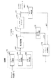
II.送信パワー制御
図4はユーザ端末トランシーバ200 の可能なパワー制御方式の詳細を示している。受信された信号は復調器401 へ入力される。1実施形態では、復調器401 はA/D変換器402 、疑似ランダム雑音(PN)相関器404 、PN発生器406 を含んでいる。受信された信号はA/D変換器402 によりアナログからデジタル形態へ変換される。A/D変換器402 からのデジタル信号出力は相関器404 へ与えられ、相関器404 では信号は相関処理を受け、これは同意のために信号を局部基準に比較する。図示されている実施形態では、相関器404 はPN相関器である。したがって、信号はPN発生器406 により与えられるPN信号との相関処理を受ける。変調器401 の出力407 は好ましくは量子化装置408 へ与えられる。量子化装置408 の出力409 (または量子化装置408 が使用されていないならば出力407 )は、特定のグループのサンプルされた信号がウォルシュコードを使用して通常構成される1組の直交コード内からの特定の直交コードに対応する信頼性の尺度に対応しているソフト決定データを含むことができる。この量子化装置408 の出力409 (または直接的に出力407 )は前述したユーザデジタルベースバンド回路224 へユーザデータを提供するためユーザデータデコーダ410 へ与えられる。デコーダ410 は評価されたトラフィックチャンネルデータビット411 (ユーザデータとも呼ばれる)を発生するための最大の確率デコード技術を使用する。最大の確率デコード技術は関連技術でよく知られているビタビ復号アルゴリズムに実質上類似のアルゴリズムを使用することによって強化されてもよい。
【0047】
復調器401 と量子化装置408 のコンポーネントは前述のデジタルデータ受信機216 のコンポーネントであることが予期される。さらに、デコーダ410 のコンポーネントは前述したように、ダイバーシティ結合装置およびデコーダ回路222 のコンポーネントであることが予測される。
【0048】
ユーザ端末126 のようなユーザ端末で受信した信号品質はユーザ端末により測定される。この測定から、信号パワーの適切レベルが決定され、ここでは不適切な貧弱な信号品質は不十分な信号パワーの指示である。例えば、信号対雑音比(SNR)評価装置418 は量子化装置408 の出力409 (または直接的に出力407 )に基づいて受信された信号のSNRを評価できる。その代わりに、または付加的に信号品質はフレームエラーのようなエラーに基づいて測定されることができる。例えばエラー検出器416 はエラーが発生しているか否かをフレーム毎を基礎として決定することができる。エラー検出器416 はCRCビットまたは情報のような、しかしそれに限定せずによく知られた技術を使用してフレームエラーを検出することができる。
【0049】
SNR評価装置418 および/またはエラー検出器416 の出力はパワーコマンド決定装置420 へ与えられる。パワーコマンド決定装置420 は(受信された信号の送信に使用される)送信機パワーが受信された信号の品質に基づいて調節されるべきであるか否かを決定する。特に、パワーコマンド決定装置420 はパワーアップまたはパワーダウンコマンドを発生でき、これはユーザ端末126 から例えばゲートウェイ122 へ送信されるパワーアップまたはパワーダウンリクエストメッセージを発生するために使用される。一度、ゲートウェイ122 で受信されると、これらのパワー調節メッセージは送信プロセッサ330 へ与えられ、これは送信パワー制御装置328 にユーザ端末126 へ送信される信号のパワーを増加または減少させる。
【0050】
パワーコマンド決定装置420 はSNRおよび/またはフレームエラーのような信号品質の尺度に基づいて送信された信号パワーのこのような調節をリクエストできる。高レベルでは、パワー制御決定装置420 は信号品質測定結果を信号品質しきい値と比較する。測定された信号品質が対応するしきい値を超えるならば、パワーコマンド決定装置420 はゲートウェイ122 が特定の量だけ、所望のように増加または減少するようにその送信された信号パワーを変更する。付加的に、測定された信号品質がしきい値を超えないならば、パワーコマンド決定装置420 はゲートウェイ122 がその送信された信号パワーを特定の量だけ変更でき、それによってパワーを節約し、可能な信号干渉を減少し、ここでは所望のように減少または増加する。
【0051】
特に、パワーコマンド決定装置420 はSNR評価装置418 からの出力419 を使用して受信された信号の測定されたSNRに基づいてゲートウェイ122 の送信機のパワーの調節を決定できる。したがってパワーコマンド決定装置420 はSNRが予め限定されたしきい値よりも下に落ちるならばゲートウェイ122 の送信パワーが予め定められた量だけ増加されるべきであることを決定し、SNRが予め限定されたしきい値を超えるならば予め定められた量だけ減少されるべきであることを決定する。
【0052】
代わりにおよび/付加的に、パワーコマンド決定装置420 はエラー検出器416 からの出力を使用して受信された信号のFERを決定することができる。したがって、パワーコマンド決定装置420 はFERが予め定められたしきい値を超える(例えば1%)ならばゲートウェイ122 の送信機パワーが予め定められた量だけ増加されるべきであることを決定でき、またはFERが予め限定されたしきい値よりも低いならば予め定められた量だけ減少されるべきであることを決定する。
【0053】
代わりに、以下詳細に説明されるように、パワーコマンド決定装置420 は測定された/評価されたSNRとSNRしきい値との比較に基づいて送信パワーの調節を決定でき、FERが予め定められたFERしきい値よりも下に落ちているかそれを超過しているかに基づいてSNRしきい値を調節することができる。
【0054】
FERはエラーのない受信されたフレームに比較されるエラーを有して受信されたフレーム数に基づいた計算である。SNRは送信される使用可能な信号と雑音または不所望な信号の比率である。ビットエラー率(BER)等の信号品質の代わりの尺度の使用も本発明の技術的範囲内である。
【0055】
説明する例示的な実施形態では、“送信機パワー”または“送信パワー”の調節(増加または減少)に対する用語は、ゲートウェイ122 がユーザ端末126 のような特定のユーザ端末へ信号を送信するために使用されるパワー量を調節することを意味している。パワーコマンド決定装置420 の付加的な詳細について以下説明する。
【0056】
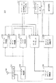
III .好ましい実施形態
図5は本発明の好ましい実施形態による別のパワー制御方式を示している。図5で示されているパワー制御方式は、復調器401 、(好ましいが必ずしも必要ではない)量子化装置408 、ユーザデータデコーダ410 、エラー検出器416 および/またはSNR評価装置418 、パワーコマンド決定装置420 を含んでいる点で、図4のパワー制御方式と類似している。しかしながら、図5の実施形態は幾つかの顕著な方法で異なる。第1に、図5のパワー制御方式はまた歪み装置412 およびバーチャルデコーダ414 も含んでいる。付加的に、この実施形態では、SNR評価装置への入力は量子化装置408 の出力(または直接的に出力407 )ではなく、歪み装置412 の出力413 である。さらに、エラー検出器416 への入力はユーザデータデコーダ410 の出力411 (ユーザデータ)ではなく、バーチャルデコーダ414 の出力415 である。
【0057】
ユーザデータデコーダ410 とバーチャルデコーダ414 は物理的に異なるコンポーネントであることに留意する。代わりに、データデコーダ410 とバーチャルデコーダ414 は2つのデコーダとして機能するように時間多重化される1つのデコーダであってもよい。
【0058】
歪み装置412 は例えば疑似雑音を出力409 へ付加することによって量子化装置408 の出力409 (または直接的に出力407 )を歪ませる。歪み装置412 の効果は量子化装置408 の出力409 (または出力407 )を悪化させることである。例えば量子化装置408 の出力409 がソフト決定データである実施形態では、歪み装置412 の出力413 はサンプルされた信号の特定のグループが特定の直交コードに対応する信頼性のレベルに対応してソフト決定データを歪ませる。歪み装置412 により、出力412 に対応する信頼性のレベルは出力409 と比較して少なく/減少される。
【0059】
バーチャルデコーダ414 を参照すると、バーチャルデコーダ414 の出力はデジタルベースバンド回路224 に与えられるユーザデータではないので、用語“バーチャル”が使用される。ユーザデータデコーダ410 からの出力411 は、図4の説明で前述した方法と類似の方法でデジタルベースバンド回路224 へ与えられる。しかしながら、(図4のように)ユーザデータデコーダ410 の出力411 ではなくバーチャルデコーダ414 の歪ませられた出力415 はパワー制御に使用される。即ち、エラー検出器416 は出力411 ではなくバーチャルデコーダの出力415 に基づいてエラーを決定する。これによってエラー検出器416 が(図4で示されているように)実際のユーザデータ411 に基づいてエラーを決定する場合よりも検出されるエラー量は高くなる。
【0060】
付加的に、歪まされた出力413 はSNR評価装置418 へ与えられる。SNR評価装置418 は歪まされたデータ413 のSNRを測定/評価しているので、パワーコマンド決定装置420 へ与えられる評価されたSNR419 は量子化装置408 の出力(即ち409 )の実際のSNRよりも低い/悪い。
【0061】
図5の実施形態では、パワーコマンド決定装置420 は“誤”信号品質測定値に基づいて送信パワーの調節をリクエストするかどうかを決定する。即ち、パワーコマンド決定装置420 は信号品質が実際よりも悪いことを示す入力に基づいて決定を行う。例えば、SNR評価装置418 は図4のパワー制御方式を使用するときと比較して図5のパワー制御方式を使用するときにSNRが低いことを評価している。さらに、歪まされたデータ413 がバーチャルデコーダ414 へ与えられるので、バーチャルデコーダ414 はユーザデータデコーダ410 よりも多くのフレームエラーを生成する。したがってエラー検出器416 は図4の方式で使用するときと比較して図5のパワー制御方式で使用するとき増加した量のエラーを検出する。それ故、図5のパワー制御方式で使用するときのパワーコマンド決定装置420 は、図4のパワー制御方式で使用される場合よりも早期にしきい値が超過されることを決定する(同一のしきい値が両方式で使用されることを想定している)。これは信号品質しきい値が実際に歪みのない復調された信号409 (または407 )および/またはユーザデータ411 に到達される前に、パワーアップまたはダウンコマンドをパワー制御決定装置420 に発生させる。
【0062】
IV.パワー制御決定装置の動作
パワーコマンド決定装置420 は米国特許出願第09/164,384号明細書(発明の名称“System and Method for Optimized Power Control ”、1998年9月30日)と米国特許出願第09/183,388号明細書(発明の名称“Variable Loop Gain in Double Loop Power Control Systems ”、1998年10月29日)に開示されているパワー制御特徴を実行できる。完全性の目的で、本発明が先に参照した特許明細書の特徴と組合わせて使用されることができる態様の説明は図6および7の説明で行われる。
【0063】
図6および7は本発明の好ましい実施形態にしたがって、パワーコマンド決定装置420 、SNR評価装置418 、エラー検出器416 の動作を示したフローチャートである。図6は内部パワー制御ループの動作を示している。図6のステップはSNR評価装置418 とパワーコマンド決定装置420 により実行される。内部パワー制御ループの機能はゲートウェイ122 により送信される信号パワーを調節することである。
【0064】
前述の例示的な実施形態では、送信された信号パワーはトランシーバ200 で受信された信号パワーのレベルにしたがって調節される。特に、これらの例示的な実施形態では、ゲートウェイ122 は信号をユーザ端末126 へ送信する。信号は復調器401 により復調され、(好ましくは)量子化装置408 により量子化される。信号の量子化された表示(即ち出力409 )は前述したように、信号の歪まされた量子化された表示を出力する歪み装置412 へ与えられる。歪み装置412 の出力413 は歪まされた復調された信号413 と呼ばれる。
【0065】
ステップ502 で示されているように、プロセスは歪まされた信号413 のパワーのSNR評価装置による測定で開始する。好ましい実施形態では、SNR評価装置418 は歪まされた信号413 の信号対雑音比(SNR)を測定する。特に、SNR評価装置は量Eb /N0 を測定し、ここで、Eb はビット当りのエネルギであり、N0 はパワー/サイクルの単位の雑音密度である。勿論、信号パワーの他の測定は本発明の技術的範囲を逸脱することなく使用されることができる。好ましい実施形態では、SNRは受信されるデータのフレーム毎に測定される。
【0066】
通信システム100 では、“SNRしきい値”と呼ばれる予め定められたSNRレベルはトランシーバ200 と関連される。SNRしきい値は信号がデータ品質を確実にするためにトランシーバ200 により受信されるべき最小のSNRを表している。SNRしきい値は関連技術でよく知られている方法にしたがって選択されることができる。1つのこのような方法は1パーセントのようなあるパーセントより下にデータエラーを維持するSNRを選択することである。ステップ504 では、パワーコマンド決定装置420 はステップ502 で測定されたSNRをSNRしきい値と比較する。
【0067】
測定されたSNRがSNRしきい値よりも低いならば、パワーコマンド決定装置420 はステップ506 で示されているように、パワーアップメッセージをゲートウェイ122 へ送信させる“増加パワー”コマンドを発生する。それに応答して、ゲートウェイ122 は内部ループの“利得”または“内部ループ利得”と呼ばれる予め定められた量(例えば0.5dB)だけ送信された信号パワーを増加する。
【0068】
測定されたSNRがSNRしきい値を超えているならば、トランシーバ200 のパワー制御決定装置420 はステップ508 で示されているように、パワーダウンコマンドをゲートウェイ122 へ送信させる“減少パワー”コマンドを発生する。それに応答して、ゲートウェイ122 は特定量(例えば0.004dB)だけ信号パワーを減少する。
【0069】
前述したように、“エラーイベント”またはエラー率の存在を測定またはそれに依存する技術のようなパワーレベルに反比例して変化するSNR以外の品質尺度機能が使用される場合、信号パワーは測定値がしきい値から変化する程度まで反比例関係で調節される。即ち、測定された値がしきい値を超えたとき、信号パワーは増加され、しきい値よりも小さいとき、信号パワーは減少される。
【0070】
図7は本発明の実施形態で使用される外部パワー制御ループ(“外部ループとも呼ばれる”)の動作を示している。図7のステップは同様にエラー検出器416 およびパワーコマンド決定装置420 により実行される。外部パワー制御ループの機能はトランシーバ200 のSNRしきい値を調節することである。好ましい実施形態ではSNRしきい値は受信された信号の品質にしたがって調節される。好ましい実施形態では、信号の品質は現在のフレームだけでなくある数の先のフレームに対しても考慮される。また、好ましい実施形態では、使用される信号品質尺度は測定されたFERである。しかしながら、パリティチェック等の信号品質の他の尺度が本発明の技術的範囲を逸脱せずに使用されることができる。
【0071】
図7を参照すると、ステップ602 で示されているように、プロセスは歪まされたデータ415 (歪ませられた決定データとも呼ばれる)の現在のフレームがエラーであるか否かを決定することから開始する。その後、ステップ604 で示されているようにプロセスはエラーが現在のフレームに存在するか否かを決定する。ステップ604 から“ノー”分岐路で示されているように、エラーが現在のフレームに存在しないならば、ステップ606 で示されているように、パワーコマンド決定装置420 は予め定められた量だけSNRしきい値を減少させる。しかしながら、ステップ604 から“イエス”分岐路で示されているように、エラーが現在のフレームに存在するならば、ステップ608 で示されているように、プロセスは受信された信号の品質経歴を吟味する。好ましい実施形態では、エラー経歴は予め定められた数の先のフレームを含んでいる。勿論、エラー経歴は本発明の技術的範囲を逸脱せずに他の方法で選択されることができる。エラー経歴はメモリ(図示せず)に保存されている。任意の先のN個のフレームがエラーを含んでいるならば、パワーコマンド決定装置420 はステップ606 で示されているように、外部ループ利得によりSNRしきい値を減少する。
【0072】
しかしながら、先のN個のフレームがエラーを含んでいないならば、パワーコマンド決定装置420 はステップ610 で示されているように、SNRしきい値を増加する。好ましい実施形態では、2つの変化値が使用され、一方はSNRしきい値を減少させる値であり、他方はSNRしきい値を増加させる値である。SNRしきい値を減少する変化値は比較的小さく、それによってSNRしきい値と内部ループの動作を通じて、送信された信号パワーは漸進的にエラーのない環境で減少される。反対に、SNRしきい値を増加する変化値は比較的大きく、それによってSNRしきい値と内部ループの動作を通じて、送信された信号パワーは迅速にエラーのありがちな環境で増加される。
【0073】
図6および7の説明で示されているパワーコマンド決定装置420 の動作は、図4と5のパワー制御方式において使用されることができる。しかしながら、図5の方式を使用する利点は、図5のパワー制御方式を使用するときに検出されるフレームエラーに応答したSNRしきい値の必要な量の増加(即ち外部ループ利得)が図4の方式を使用するときよりも小さいことである。さらに、図5のパワー制御方式を使用するときのSNRしきい値の減少(ステップダウン)量は図4のパワー制御方式で使用するときよりも大きい。全送信パワーがSNRしきい値の増加および減少をおおまかに生じるので、全送信パワーは図5のパワー制御方式を使用するときに減少される。
【0074】
図4および5のパワー制御方式は信号が衛星116 を経てゲートウェイ122 からユーザ端末126 へ送信されるように説明されている。即ち、図4と5のパワー制御方式は図4と5で示されているコンポーネントがユーザ端末126 に位置され、ゲートウェイ122 の送信パワーが制御されるものとして説明されている。同一のパワー制御方式はユーザ端末126 が基地局112 から信号を受信しているならば使用されることができることに注意すべきである。唯一の差は、パワーコマンド決定装置420 がゲートウェイ122 により使用されるパワーを調節するか否かではなく、信号をユーザ端末126 へ送信するために基地局112 により使用されるパワーを調節するか否かを決定することである。前述のパワー制御方式がユーザ端末126 により使用されるように説明されているが、比較的同一の方式がユーザ端末126 が信号をゲートウェイ122 または基地局112 へ送信するために使用するパワーを調節するためにゲートウェイ122 または基地局112 により使用されることができることに注意すべきである。即ち、例えば図4と5のコンポーネントはゲートウェイ122 に位置され、制御される送信パワーは信号を衛星118 を経てゲートウェイ122 へ送信するときのユーザ端末126 の送信パワーである。さらに、図4、5のパワー制御方式は信号を基地局112 へ送信しているときユーザ端末126 の送信パワーを調節するために使用される。
【0075】
V.本発明の高レベルの動作
図8は本発明の好ましい実施形態の高レベル動作を示したフローチャートである。ステップ702 で示されているように、プロセスは受信された信号を復調するステップで開始する。復調された信号はステップ704 で歪ませられる。これは例えば雑音を復調された信号へ付加することにより行われてもよい。次に、ステップ706 で、信号品質測定値は(変調されていない信号ではなく)歪みを有する変調された信号に基づいて決定される。この信号品質測定値は例えばSNRの測定値である。最終的に、ステップ708 では、送信パワーの調節はステップ706 で決定された信号品質測定値に基づいてリクエストされる。
【0076】
ステップ708 はステップ710 、712 、714 、716 を含むことができる。ステップ710 では、ステップ706 で決定された信号品質測定値はしきい値と比較される。ステップ712 では、信号品質測定値がしきい値を超えるか否かについての決定が行われる。ステップ712 の回答がイエスであるならば、送信パワーの増加(例えば+0.5dB)がリクエストされる。ステップ712 の回答がノーであるならば、送信パワーの減少(例えば−0.5dB)がリクエストされる。
【0077】
ステップ710 、712 で使用されるしきい値は前述したように、信号品質の第2の測定値に基づいて調節されることが好ましい。例えば、歪みを有する復調された信号が歪ませられた決定データを発生するために復号されることができる。フレームエラーの測定値は歪ませられた決定データに基づいて決定される。ステップ710 および712 で使用されるしきい値はその後、フレームエラーのこの測定値に基づいて調節されることができる。
【0078】
好ましい実施形態では、ステップ710 、712 で使用されるしきい値が調節されるならば、ユーザ端末126 が図5のパワー制御方式を使用される場合、パワー制御決定装置420 は、ユーザ端末126 が図4の方式を使用する場合にそのSNRしきい値を増加しなければならない程度にステップ610 においてそのSNRしきい値を増加する必要はないことに注意すべきである。特に、ゲートウェイ122 のパワー調節がSNRしきい値との比較に基づいていると仮定する。ユーザ端末126 がゲートウェイ122 の信号送信パワーを制御するために図4のパワー制御方式を使用するならば、パワーコマンド決定装置420 はステップ610 の増加したSNRしきい値コマンドの受信に応答して約3dBだけそのSNRしきい値を増加する必要があり、それによって(歪みのない復調された信号409 または407 の)FERがしきい値FERより下に落ちないことを確実にする。それと対照的に、(同一の無線通信システム内および同一位置の)同一のユーザ端末126 が図5のパワー制御方式を使用するならば、パワーコマンド決定装置420 は歪みのない復調された信号409 または407 の実際のFERはFERしきい値よりも下に落ちない、例えば0.5dB等、そのSNRしきい値の増加よりも少量の増加を必要とする。ゲートウェイ122 の送信機パワーはSNRしきい値の変化を生じる。これは図5の方式を使用するとき、実際のSNR(即ち復調された信号407 または409 のSNR)がSNRしきい値よりも下に落ちる前にしきい値が増加されるためである。ゲートウェイ122 の送信機パワーが基本的にSNRしきい値の増加および減少にしたがうので、これはユーザ端末126 が図4の方式で使用される場合と同程度にゲートウェイ122 がそのパワーを増加する必要をなくす。ゲートウェイ122 の送信機パワーはパワーコマンド決定装置420 により行われるパワーアップ(例えば+0.5dB)とパワーダウン(例えば−0.5dB)リクエストに基づき、これらのリクエストはSNRしきい値との比較に基づくので、ゲートウェイ122 のパワーは基本的にSNRしきい値の変化にしたがう。
【0079】
さらに、図4のパワー方式では、FERがFERしきい値よりも下に低下しないことを確実にするため、パワーダウンコマンドに応答するSNRしきい値の増加量は比較的低く、例えば0.001dBである。対照的に、SNRしきい値は図5のパワー方式を使用するときパワーダウンコマンドに応答してさらに迅速に、例えば0.004dBステップダウンされることができる。これは、SNRしきい値(したがってゲートウェイ送信機パワー)が実際のSNR(即ち復調された信号407 または409 のSNR)がSNRしきい値に到達する前に増加されるためである。
【0080】
図9のAの例示的なグラフは、ユーザ端末126 が図4のパワー制御方式を使用するときの時間にわたるSNRしきい値を示している。図9のAから認められるように、パワー制御決定装置420 は時間t1 でSNRしきい値を増加する。この例では、パワー制御決定装置420 はステップ610 の増加したSNRしきい値コマンドの受信に応答して3dBだけSNRしきい値を増加する。時間t1 に先立った時間では、例えばフレームエラーが検出されないとき、パワー制御決定装置420 はステップ606 でSNRしきい値を減少する。この例では、パワー制御決定装置420 がステップ606 で減少したSNRしきい値コマンドの受信に応答して0.001dBだけSNRしきい値を減少すると仮定する。代わりに、パワー制御決定装置420 は時間t1 で増加したSNRしきい値コマンドを受信するまで時間にわたってSNRしきい値を独立して減少させてもよい。
【0081】
さらに、図9のAを参照すると、ゲートウェイ122 が信号送信に使用するパワーが基本的にSNRしきい値に従うので、鋸歯状曲線の下の区域はゲートウェイ122 が時間にわたり信号をユーザ端末126 へ送信するために使用する総パワー量にほぼ比例する。本発明の目的は所望の信号品質を維持しながら総パワー量を減少することである。したがって、総パワーの減少は鋸歯状曲線下の区域での減少により示されることができる。
【0082】
図9のBはユーザ端末126 が図5のパワー制御方式を使用しているとき、時間にわたるSNRしきい値を示している。図9のBから認められるように、パワーコマンド決定装置420 は例えばフレームエラーが検出されたとき(N個の先のフレームで検出されていないとき)、時間t1 ´ 、t2 ´ 、t3 ´ でSNRしきい値を増加する。ステップ610 で増加したSNRしきい値コマンドの受信に応答するSNRしきい値の増加は図9のAの3dBと比較すると、0.5dBに過ぎない。さらに、SNRしきい値はステップ606 の減少したSNRしきい値コマンドに応答してさらに迅速にステップダウンされ、これは(例えばt1 ´ とt2 ´ の間の時間で)フレームエラーが検出されたときに生じる。
【0083】
図9のAと図9のBのグラフはほぼ同一のスケールで書かれている。即ち図9のAと図9のBを参照するとき、増加したSNRしきい値コマンドの受信に応答して、SNRしきい値の増加は図9のAでは図9のBよりも非常に大きい(0.5dBと比較して3dB)ことが認められる。さらに、減少したSNRしきい値の受信に応答して、SNRしきい値は図9のAでは図9のB程迅速にステップダウンされない(0.004dBと比較して0.001dB)。したがって、図9のBのSNRしきい値の減少を表す特性曲線の勾配は図9のAの勾配よりもほぼ4倍大きいことが認められる。ゲートウェイ122 の送信機パワーは基本的にSNRしきい値の変化に従うので、これらの2つのグラフは、(図9のAのグラフに対応する)図4のパワー制御方式を使用するときに必要な送信機パワー量が、(図9のBのグラフに対応する)図5のパワー制御方式を使用するときに必要な送信機パワー量よりも非常に大きいことを示している。したがって、図5のパワー制御方式の使用はリソースを節約し、可能な信号干渉を減少する。
【0084】
二重ループ構造を使用して前述したような適応的なパワー制御方式はパワーアップまたはパワーダウンコマンドの供給を決定するためにSNRの測定とエラーの測定との両者に依存する。適応性ではない方式では、測定されたSNRが幾つかの固定したしきい値よりも上であるか下であるかを単に検出するだけで十分である。しかしながら、適応性の技術では、しきい値自体は検出されたエラー数(いわゆる外部ループ)にしたがって変化しなければならない。1%のような比較的高いFERを実現することはかなり実際的であるが、類似した大きさだけ低くされたエラー率は実際的ではない。理由は高いSNRと、それ故低いFERで動作しているシステムでは、SNRが十分に低いために非常に高いFERが実現されしきい値が再度値でラチェットされまたはステップアップされるまで、エラーのない状態はしきい値を漸進的に低くする。これによって非常に低いFERと低いドリフティングの期間の間の交替はFERを非常に高くする。しかしながら、所望されることは低いFERでの安定な動作である。SNRの測定とFERとの両者が劣化されるように受信された信号を歪ませるためバーチャルデコーダが設けられ、バーチャルデコーダがパワー制御コマンドを発生するが、同時に真の復調された/復号されたデータをリリースしている並列した歪みのない受信機が存在するならば、バーチャルデコーダは1%のような正規の低いFERで動作でき、真のデコーダは1以上の類似の大きさだけ低いFERで動作している。
【0085】
本発明が有効に使用されることができる1つの領域は新しいコード化/デコード技術(例えばターボコード化)の応用である。これらの場合、SNR対BERまたはFER間の関係は非常に急峻な勾配を有する曲線として観察されることができる。即ち、SNRが少し高すぎまたは低すぎるとき、さらに大きな量または類似の大きさだけエラー率を変化できる。このような技術は導出されたSNRで幾らか変化を起こし、これはエラー率で類似した大きさの変化を生じるため、このようなコード化が使用されるとき適応的な(例えば二重ループ)パワー制御技術を使用することは非常に困難である。前述したバーチャルデコーダ技術の使用は“バーチャルデコーダ”が曲線の急峻ではない、または急峻度の少ない領域で動作することを可能にし、エラー率への影響が少ないが、実際のデコーダは高い(劣化のない)SNRで急峻な領域で動作する。急峻ではない部分でのバーチャルデコーダの動作はSNR変化を小さく維持することを可能にする。
【0086】
本発明が非常に有効に使用されることができる別の区域は、パワー制御が非常に低い待ち時間で低いフレームエラー率で必要とされるケースである。2つの類似した例はT搬送波ファシリティと、非同期転送モード(ATM)トラフィックの地上または衛星によるデータ転送である。T搬送波ファシリティは顧客とサービスプロバイダとの間のトラフィックの混合を表し、ここでトラフィックはデジタル化された音声、デジタルビデオ会議、インターネット、ファイル転送トラフィックの混合である。このような応用では、標準的なサービスは低いエラー率であり、いずれかの端部に組込まれたプロトコルは低い待ち時間を想定する。このタイプのサービスを与える無線リンクはデータを伝送するための同一特性を示さなければならない。ATMサービスでは、最も簡単なケースの音声またはビデオデータのこれらのサービスは、このような実時間サービスの符号化/復号化処理が送信の必要無しに通常かなり高いエラー率に耐えるように組込まれているので低いエラー率を必要としない。しかしながら、各ATMパケット(セル)は高いエラー率を使用できるペイロード情報またはデータだけでなく、損失を抑制するために低いエラー率を必要とするアドレス情報も含んでいる。通常、反復するパケットは実時間サービスでは許容されず、また可能ではない。それ故、前述のバーチャルデコーダアレンジメントの使用は、適切であるように低いフレームエラー率を与え必要な低い待ち時間を維持する能力によって、このようなサービスに対するエラー率に対して改良された制御を可能にする。
【0087】
本発明の好ましい実施形態の前述の説明は当業者が本発明を実行または使用することを可能にするために与えられた。これらの実施形態に対する種々の変形は当業者に容易に明白であり、ここで規定されている一般原理は発明力を使用せずに他の実施形態にも適用されることができる。したがって、本発明はここで示されている実施形態に限定されることを意図するものではなく、ここで説明されている原理および優れた特徴と一貫した最も広い範囲に従うことを意図している。
【図面の簡単な説明】
【図1】 本発明が有効である典型的な通信システムの図。
【図2】 ユーザ端末で使用するための例示的なトランシーバ装置の図。
【図3】 ゲートウェイで使用するための例示的な送信および受信装置の図。
【図4】 パワー制御方式のブロック図。
【図5】 本発明の好ましい実施形態にしたがったパワー制御方式のブロック図。
【図6】 本発明の1実施形態のパワー制御決定装置により使用される内部パワー制御ループの動作を示すフローチャート。
【図7】 本発明の1実施形態のパワー制御決定装置により使用される外部パワー制御ループの動作を示すフローチャート。
【図8】 本発明の好ましい実施形態の高レベル動作を示すフローチャート。
【図9】 図4のパワー制御方式を使用しているユーザ端末における時間にわたるSNRしきい値および図5のパワー制御方式を使用しているユーザ端末における時間にわたるSNRしきい値の特性図。[0001]
BACKGROUND OF THE INVENTION
The present invention relates to wireless communication systems, and more particularly to a method and apparatus for reducing frame error rate (FER) in wireless communication systems.
[0002]
[Prior art]
When transferring data over a radio link with a relatively poor FER (eg greater than 1%), there are many ways to retransmit the data to achieve the FER as low as the data service requires. To do. For example, a cyclic redundancy code check scheme (CRC) can be performed at the receiving end of a link to check the integrity of a block of data. CRC is a well-known method of setting that data has been received correctly in data communication. The CRC code is generated at the transmitter and attached to the data block. The receiving end performs a similar calculation and compares the result with the appended CRC code. If there is a difference, the receiving end requests a retransmission of the data block.
[0003]
For example, the use of a protocol such as automatic retransmission request (ARQ) can be used for retransmission of data blocks. In ARQ, the transmitter encodes an error detection field (eg, CRC field) based on the data block. The receiving end calculates the check field again and compares it with the received one. When they match, an acknowledgment (ACK) is returned to the transmitting device. If they do not match, a negative acknowledgment (NAK) is returned and the sending device sends the message again.
[0004]
[Problems to be solved by the invention]
The method described above is satisfactory for the transmission of many types of data. However, methods that achieve low FER increase latency by retransmitting data blocks. Such increased latency cannot be tolerated when transmitting certain types of data, such as real-time digitized voice or other types of latency sensitive data. In particular, retransmission of a data block results in a delay time, which is high on average, and in systems that are sensitive to multiple latencies, there is a greater change than required.
[0005]
What is needed is a method and apparatus for transferring data with low FER without increasing latency, in other words, there is a need for a method and apparatus for reducing FER without relying on retransmission of data blocks. Yes.
[0006]
[Means for Solving the Problems]
The present invention relates to a method and apparatus for controlling signal transmission power. The method of the present invention includes the steps of demodulating a received signal to generate a demodulated signal, and distorting the demodulated signal to generate a distorted demodulated signal. The demodulated signal can be distorted, for example, by adding noise. Signal quality measurements such as signal-to-noise ratio are determined based on the distorted demodulated signal rather than the demodulated signal. Transmission power adjustment is requested based on the signal quality measurement result of the distorted demodulated signal.
[0007]
In one embodiment of the present invention, the determined signal quality measurement is compared to a threshold value and a transmission power adjustment is requested based on the comparison result. The threshold represents the desired minimum signal quality level at which the signal is to be received. Some quality measurement functions, such as SNR, have values that are proportional to signal quality. That is, they increase with increasing quality and decrease with decreasing quality. Therefore, if these signal quality measurements fall below the threshold, an increase in transmit power is requested, and if the signal quality measurement exceeds the threshold, a decrease in transmit power is requested. . Other functions have values that are inversely proportional to signal quality based on error events, with values decreasing with increasing signal quality, and vice versa. In this state, if the measured value falls below the threshold, a decrease in transmission power is requested, and if the measured value exceeds the threshold, an increase in transmission power is requested.
[0008]
In one embodiment, the method of the present invention further includes the steps of decoding the demodulated signal to generate decision data and decoding the distorted demodulated signal to generate distorted decision data. A second signal quality measurement or “error event” measurement is determined based on the distorted decision data (not the decision data). The threshold used to determine the increase or decrease in transmit power is adjusted based on the second signal quality measurement.
[0009]
In one embodiment where the signal is transmitted by the base station and received by the user terminal, the steps of the invention are performed by the user terminal to control the transmission power of the base station.
In another embodiment of the invention in which the signal is transmitted by the gateway and received by the user terminal using a satellite, the steps of the invention are performed by the user terminal to control the transmission power of the gateway.
[0010]
In yet another embodiment where the signal is transmitted by the user terminal and received by the base station, the transmission power of the user terminal is controlled.
In yet another embodiment of the invention in which the signal is transmitted by a user terminal and received by a gateway using a satellite, the steps of the invention are performed by the gateway to control the transmission power of the user terminal.
[0011]
DETAILED DESCRIPTION OF THE INVENTION
The features, objects and advantages of the present invention will become more apparent from the following detailed description when taken in conjunction with the drawings. The same reference signs refer to the same or similar elements throughout.
Preferred embodiments of the invention are described in detail below. Although specific steps, structures, and arrangements are described, it should be understood that this is done for illustrative purposes only. Those skilled in the art will recognize that other steps, structures, and arrangements can be used without departing from the scope of the present invention.
[0012]
I. Example environment
Before describing the present invention in detail, it is useful to describe an exemplary environment in which the present invention can be implemented. The present invention can be implemented in a number of wireless communication systems, particularly systems that are desirable for controlling the amount of power used to transmit signals. Such environments include, but are not limited to, satellite and terrestrial cellular telephone systems. A preferred application is in code division multiple access (CDMA) radio spread spectrum communication systems for mobile or portable telephone services.
[0013]
The present invention is particularly suitable for use in communication systems using low earth orbit satellites. However, as will be apparent to those skilled in the art, the concepts of the present invention are applicable to other types of satellite and terrestrial communication systems.
[0014]
Typically, a satellite-based communication system uses a gateway and one or more satellites for relaying communication signals between the gateway and one or more user terminals. The gateway provides a communication link from each user terminal to other user terminals or users of other connected communication systems such as public switched telephone networks. A typical terrestrial system uses a base station to transmit signals and receive signals from user terminals. The user terminal is fixed or movable like a mobile phone.
[0015]
Some satellite and terrestrial communication systems are described in U.S. Pat. No. 4,901,307 (Title of Invention “Spread Spectrum Multiple Access Communication System Using Satellite or Terrestrial Repeaters”, Feb. 13, 1990) and U.S. Pat. No. 5,691,974. Code division multiple access as described in the document (“Invention name“ Method and Apparatus for Using Full Spectrum Transmitted Power in a Spread Spectrum Communication System for Tracking Individual Recipient Phase Time and Energy ””, November 25, 1997) (CDMA) spread spectrum signals are used.
[0016]
In a typical spread spectrum communication system, one or more preselected pseudo-noise (PN) code sequences modulate an information signal over a predetermined spectral band before modulating the carrier signal for transmission as a communication signal. Or used to "diffuse". PN code spreading, a spread spectrum transmission method well known in the art, generates a signal for transmission with a much larger bandwidth than the data signal. In base station or gateway-user communication links, PN spreading codes or binary sequences are used to distinguish between signals transmitted by different base stations or gateways or different beams and between multipath signals.
[0017]
In a typical CDMA spread spectrum system, the channelization code is between signals destined for different users in the cell or in a satellite sub-beam on the forward link (ie, the signal path from the base station or gateway to the user terminal transceiver). Used to discriminate between user signals transmitted in Each user transceiver has its own orthogonal channel provided in the forward link by using a unique “channelized” orthogonal code. The signals transferred on these channels are usually called “traffic signals”. Additional channels are provided for "paging", "synchronization" and other signals transmitted to system users. Walsh functions are typically used to construct a channel or code, also known as a Walsh code.
[0018]
CDMA spread spectrum communication systems such as those disclosed in the aforementioned patent specifications allow for the use of coherent modulation and demodulation for forward link user terminal communications. In communication systems using this method, a “pilot” carrier signal, also called a “pilot signal”, is used as a coherent phase reference for the forward link signal. That is, a signal without data modulation is transmitted through the coverage area as a reference by the gateway or base station.
[0019]
The pilot signal is used by the user terminal to acquire initial system synchronization and to perform time, frequency and phase tracking of other signals transmitted by the gateway or base station. The phase information obtained from tracking the pilot signal carrier is used as a carrier phase reference for coherent demodulation of other system signals or traffic (data) signals. This technique allows multiple traffic signals to share a common pilot signal as a phase reference, providing an inexpensive and more efficient tracking mechanism. One pilot signal is transmitted by each gateway or base station for each frequency used, typically called a CDMA channel or sub-beam, and is shared by all user terminals receiving signals from that gateway or base station at that frequency .
[0020]
Gateways and base stations can transmit information to the user terminal using one or more signals known as paging signals transmitted on the paging channel. For example, when a call is made to a particular mobile phone, the gateway alerts the mobile phone by a paging signal means. The paging signal indicates the presence of a call, the traffic channel used, and is used to distribute system overhead information along with user terminal specific messages. A communication system may have several paging channels. The synchronization signal can also be used to transfer useful system information to facilitate time synchronization. All these signals act as shared resources in a manner similar to pilot signals.
[0021]
The user terminal can respond to the paging signal message by transmitting an access signal over the reverse link (ie, the signal path from the user terminal to the base station or gateway transceiver). The access signal can also be used when the user terminal originates a call.
[0022]
As with any communication system, the communication signal is received by the user terminal and down-converted to a baseband frequency for further processing. Once downconverted, the signal is digitally processed to detect specific pilot signals or received signals and to detect associated paging, synchronization and traffic signals. During demodulation, a PN spreading code is provided to despread the signal and a channelization code that is correlated with the signal to provide data.
[0023]
An exemplary wireless communication system in which the present invention is useful is shown in FIG. This communication system uses CDMA type communication signals, but this is not required by the present invention. In the portion of the
[0024]
[0025]
Typically, the beams from
[0026]
Various multi-satellite communication systems have been proposed in an exemplary system that uses as many as 48 or more satellites moving in eight different orbital planes in low earth orbit (LEO) to serve a large number of user terminals. However, those skilled in the art will readily understand how the discussion of the present invention is applicable to various satellite systems and gateway structures including other orbital distances and constellations. At the same time, the present invention is equally applicable to ground-based systems of various base station structures.
[0027]
In FIG. 1, several possible signal paths for communication between the
[0028]
An
[0029]
The digital communication signal output by the
[0030]
At least one user
[0031]
The outputs of
[0032]
The signal output from the diversity combiner and decoder circuit 222 is provided to the digital baseband circuit 224 for interfacing with the user. The user digital baseband circuit 224 includes processing and providing elements used for transferring information to and from the user terminal. That is, signal or data storage elements such as temporary or long-term digital memory, input and output devices such as display screens, speakers, keypad terminals, handsets, A / D elements, vocoders, other audio and The analog signal processing elements and the like form part of the user terminal baseband circuit 224 using elements well known in the art. Some of these elements can operate under control of or in communication with
[0033]
When voice or other data is prepared as an output message or communication signal initiated at the user terminal, the user digital baseband circuit 224 is used for receiving, storing, processing and other processing of the desired data for transmission. . User digital baseband circuit 224 provides this data to transmit
[0034]
Information or data corresponding to one or more measured signal parameters or one or more shared resource signals of the received communication signal is transmitted to the gateway using various techniques known in the art. Can do. For example, the information can be transferred as a separate information signal or processed by the user digital baseband circuit 224 and attached to other messages. Instead, the information can be inserted as predetermined control bits by the
[0035]
[0036]
Additional details of the
[0037]
An exemplary transmitting and receiving
[0038]
Although certain variations are known in the art, each
[0039]
The output of the digital data receiver 316 is provided to a subsequent
[0040]
The signals transmitted to the
[0041]
Each
[0042]
The output of transmit
[0043]
At least one
[0044]
[0045]
The
[0046]
II. Transmit power control
FIG. 4 shows details of possible power control schemes for the
[0047]
The components of
[0048]
The signal quality received at a user terminal such as
[0049]
The output of the
[0050]
The
[0051]
In particular, the power
[0052]
Alternatively and / or additionally, the power
[0053]
Instead, as described in detail below, the power
[0054]
FER is a calculation based on the number of frames received with errors compared to received frames without errors. The SNR is the ratio of available signal to be transmitted and noise or unwanted signal. The use of alternative measures of signal quality, such as bit error rate (BER), is also within the scope of the present invention.
[0055]
In the exemplary embodiment described, the term “transmitter power” or “transmit power” adjustment (increase or decrease) is used by the
[0056]
III. Preferred embodiment
FIG. 5 illustrates another power control scheme according to a preferred embodiment of the present invention. The power control scheme shown in FIG. 5 includes a
[0057]
Note that the
[0058]
The
[0059]
Referring to
[0060]
Additionally, the distorted
[0061]
In the embodiment of FIG. 5, the power
[0062]
IV. Power control decision unit operation
The power
[0063]
FIGS. 6 and 7 are flow charts illustrating the operation of the power
[0064]
In the exemplary embodiment described above, the transmitted signal power is adjusted according to the level of signal power received at
[0065]
As indicated at
[0066]
In
[0067]
If the measured SNR is lower than the SNR threshold, the power
[0068]
If the measured SNR exceeds the SNR threshold, the power
[0069]
As noted above, when a quality measure function other than SNR is used that varies inversely with power level, such as measuring the presence of an "error event" or error rate or a technology that relies on it, the signal power is measured Adjusted in inverse proportion from threshold to changing. That is, when the measured value exceeds the threshold, the signal power is increased, and when it is less than the threshold, the signal power is decreased.
[0070]
FIG. 7 illustrates the operation of the outer power control loop (also referred to as “outer loop”) used in embodiments of the present invention. The steps of FIG. 7 are similarly performed by the
[0071]
Referring to FIG. 7, as shown in
[0072]
However, if the previous N frames do not contain an error, the
[0073]
The operation of the power
[0074]
The power control schemes of FIGS. 4 and 5 are described such that signals are transmitted from the
[0075]
V. High level operation of the present invention
FIG. 8 is a flow chart illustrating the high level operation of the preferred embodiment of the present invention. As indicated at
[0076]
Step 708 can include
[0077]
The threshold used in
[0078]
In a preferred embodiment, if the threshold used in
[0079]
Further, in the power scheme of FIG. 4, the amount of increase in the SNR threshold in response to the power down command is relatively low to ensure that the FER does not drop below the FER threshold, for example 0.001 dB. It is. In contrast, the SNR threshold can be stepped down more quickly, eg, 0.004 dB, in response to a power down command when using the power scheme of FIG. This is because the SNR threshold (and hence the gateway transmitter power) is increased before the actual SNR (ie, the SNR of the
[0080]
The exemplary graph of FIG. 9A shows the SNR threshold over time when the
[0081]
Further, referring to FIG. 9A, since the power used by the
[0082]
FIG. 9B shows the SNR threshold over time when the
[0083]
The graphs of FIG. 9A and FIG. 9B are written on almost the same scale. That is, referring to FIG. 9A and FIG. 9B, in response to receiving the increased SNR threshold command, the increase in SNR threshold is much greater in FIG. 9A than in FIG. 9B. (3 dB compared to 0.5 dB) is observed. Further, in response to receiving the reduced SNR threshold, the SNR threshold is not stepped down as quickly in FIG. 9A as in FIG. 9B (0.001 dB compared to 0.004 dB). Accordingly, it can be seen that the slope of the characteristic curve representing the decrease in the SNR threshold of B of FIG. 9 is approximately four times greater than the slope of A of FIG. These two graphs are necessary when using the power control scheme of FIG. 4 (corresponding to the graph of FIG. 9A) because the transmitter power of
[0084]
An adaptive power control scheme as described above using a dual loop structure relies on both SNR measurement and error measurement to determine the supply of power up or power down commands. For non-adaptive schemes, it is sufficient to simply detect whether the measured SNR is above or below some fixed threshold. However, in the adaptive technique, the threshold itself must change according to the number of errors detected (so-called outer loop). Realizing a relatively high FER, such as 1%, is fairly practical, but an error rate reduced by a similar magnitude is not practical. The reason is that in systems operating at high SNR and hence low FER, the SNR is low enough so that a very high FER is realized and the threshold is ratcheted or stepped up again by value. The absence condition progressively lowers the threshold. This makes the alternation between very low FER and low drifting periods very high FER. However, what is desired is a stable operation at low FER. A virtual decoder is provided to distort the received signal so that both SNR measurement and FER are degraded, and the virtual decoder generates power control commands, but at the same time true demodulated / decoded data. If there is a parallel undistorted receiver releasing a virtual decoder, the virtual decoder can operate at a normal low FER, such as 1%, and a true decoder can operate at a FER lower by one or more similar magnitudes. is doing.
[0085]
One area in which the present invention can be used effectively is the application of new coding / decoding techniques (eg, turbo coding). In these cases, the relationship between SNR versus BER or FER can be observed as a curve with a very steep slope. That is, when the SNR is a little too high or too low, the error rate can be changed by a larger amount or a similar magnitude. Such techniques cause some change in the derived SNR, which produces a similar magnitude change in error rate, so it is adaptive (eg, double loop) when such coding is used. It is very difficult to use power control technology. The use of the virtual decoder technology described above allows the “virtual decoder” to operate in areas where the curve is not steep or less steep and has less impact on the error rate, but the actual decoder is high (degraded). No) Operates in a steep region with SNR. The operation of the virtual decoder in a non-steep part makes it possible to keep the SNR change small.
[0086]
Another area where the present invention can be used very effectively is the case where power control is required with very low latency and low frame error rate. Two similar examples are T-carrier facilities and asynchronous or transport mode (ATM) traffic terrestrial or satellite data transfer. The T carrier facility represents a mix of traffic between customers and service providers, where the traffic is a mix of digitized voice, digital video conferencing, Internet, and file transfer traffic. In such applications, standard services have a low error rate, and protocols built into either end assume low latency. A radio link providing this type of service must exhibit the same characteristics for transmitting data. In ATM services, these services of the simplest case of voice or video data are incorporated so that the encoding / decoding process of such real-time services usually withstands a fairly high error rate without the need for transmission. Therefore, a low error rate is not required. However, each ATM packet (cell) contains not only payload information or data that can use a high error rate, but also address information that requires a low error rate to suppress loss. Normally, repeating packets are not allowed or possible in real-time services. Therefore, the use of the virtual decoder arrangement described above allows improved control over the error rate for such services by the ability to provide a low frame error rate as appropriate and maintain the required low latency. To.
[0087]
The previous description of the preferred embodiments of the present invention has been given to enable any person skilled in the art to make or use the present invention. Various modifications to these embodiments will be readily apparent to those skilled in the art, and the generic principles defined herein may be applied to other embodiments without using inventive power. Accordingly, the present invention is not intended to be limited to the embodiments shown herein, but is to be accorded the widest scope consistent with the principles and superior features described herein.
[Brief description of the drawings]
FIG. 1 is a diagram of an exemplary communication system in which the present invention is effective.
FIG. 2 is an illustration of an example transceiver device for use with a user terminal.
FIG. 3 is a diagram of an exemplary transmitting and receiving device for use with a gateway.
FIG. 4 is a block diagram of a power control method.
FIG. 5 is a block diagram of a power control scheme according to a preferred embodiment of the present invention.
FIG. 6 is a flowchart showing the operation of an inner power control loop used by the power control determination apparatus according to the embodiment of the present invention.
FIG. 7 is a flowchart showing the operation of an outer power control loop used by the power control determination apparatus according to the embodiment of the present invention.
FIG. 8 is a flow chart illustrating high level operation of a preferred embodiment of the present invention.
9 is a characteristic diagram of an SNR threshold over time at a user terminal using the power control scheme of FIG. 4 and an SNR threshold over time at a user terminal using the power control scheme of FIG.
Claims (34)
前記復調された信号を歪ませて歪まされた復調された信号を生成し、
前記歪まされた復調された信号に基づいて信号品質に直接比例した値を表す信号品質測定値を決定し、
前記信号品質測定値に基づいて送信パワーの調節をリクエストするステップを含んでいる、データブロックの再送信に依存せずにFER(フレームエラー率)を減少させることによって低いFERを有するデータを転送する、信号送信パワーの制御方法において、
前記調節をリクエストするステップは、
前記決定された信号品質測定値を予め選択されたしきい値と比較し、
前記信号品質測定値が前記しきい値を超えた場合には送信パワーの増加をリクエストするステップを含んでおり、
前記方法はさらに、
前記復調された信号をデコードして決定データを生成し、
前記歪まされた復調された信号をデコードして歪みを有する決定データを生成し、
前記歪まされた決定データに基づいて第2の信号品質測定値を決定し、
前記第2の信号品質測定値に基づいて前記しきい値を調節するステップを含んでいる制御方法。Demodulates the received signal to generate a demodulated signal,
Distorting the demodulated signal to produce a distorted demodulated signal;
Determining a signal quality measurement representing a value directly proportional to signal quality based on the distorted demodulated signal;
Transferring data with low FER by reducing FER (frame error rate) without relying on retransmission of data blocks , including requesting transmission power adjustment based on the signal quality measurements In the signal transmission power control method,
Requesting said adjustment includes
Comparing the determined signal quality measurement with a preselected threshold;
If the signal quality measurement exceeds said threshold value includes a step of requesting an increase in transmit power,
The method further comprises:
Decoding the demodulated signal to generate decision data;
Decoding the distorted demodulated signal to generate distorted decision data;
Determining a second signal quality measurement based on the distorted decision data;
A control method comprising adjusting the threshold based on the second signal quality measurement.
前記復調された信号を歪ませて歪まされた復調された信号を生成し、
前記歪まされた復調された信号に基づいて信号品質に反比例した値を表す信号品質測定値を決定し、
前記信号品質測定値に基づいて送信パワーの調節をリクエストするステップを含んでいる、データブロックの再送信に依存せずにFER(フレームエラー率)を減少させることによって低いFERを有するデータを転送する、信号送信パワーの制御方法において、
前記調節をリクエストするステップは、
前記決定された信号品質測定値を予め選択されたしきい値と比較し、
前記信号品質測定値が前記しきい値を超えた場合には送信パワーの減少をリクエストするステップを含んでおり、
前記方法はさらに、
前記復調された信号をデコードして決定データを生成し、
前記歪まされた復調された信号をデコードして歪みを有する決定データを生成し、
前記歪まされた決定データに基づいて第2の信号品質測定値を決定し、
前記第2の信号品質測定値に基づいて前記しきい値を調節するステップを含んでいる制御方法。Demodulates the received signal to generate a demodulated signal,
Distorting the demodulated signal to produce a distorted demodulated signal;
Determining a signal quality measurement representing a value inversely proportional to signal quality based on the distorted demodulated signal;
Transferring data with low FER by reducing FER (frame error rate) without relying on retransmission of data blocks, including requesting transmission power adjustment based on the signal quality measurements In the signal transmission power control method,
Requesting said adjustment includes
Comparing the determined signal quality measurement with a preselected threshold;
If the signal quality measurement exceeds said threshold value includes a step of requesting a decrease in transmission power,
The method further comprises:
Decoding the demodulated signal to generate decision data;
Decoding the distorted demodulated signal to generate distorted decision data;
Determining a second signal quality measurement based on the distorted decision data;
A control method comprising adjusting the threshold based on the second signal quality measurement.
前記復調された信号を歪ませて歪まされた復調された信号を生成する歪み装置(412)と、
前記歪まされた復調された信号に基づいて信号品質測定値を決定する信号品質評価装置(418)と、
前記信号品質測定値に基づいて送信パワーの調節をリクエストするパワーコマンド発生器(420)とを具備する、データブロックの再送信に依存せずにFER(フレームエラー率)を減少させることによって低いFERを有するデータを転送する、信号送信パワーを制御する装置において、
前記信号品質測定値は信号品質に直接比例する値を表し、前記パワーコマンド発生器(420)は、前記信号品質測定値をしきい値と比較し、前記信号品質測定値が前記しきい値を超えた場合には送信パワーの増加をリクエストし、
前記装置はさらに、
前記復調された信号をデコードして決定データを生成するデコーダ(410)と、
前記歪まされた復調された信号をデコードして歪まされた決定データを生成するバーチャルデコーダ(414)と、
前記歪まされた決定データに基づいて第2の信号品質測定値を決定するエラー検出器(416)と、
前記第2の信号品質測定値に基づいて前記しきい値を調節する手段とを具備する、装置。 Receiving and demodulating the signal signal to demodulator for generating a signal which is demodulated (401),
A distortion device (412) for distorting the demodulated signal to generate a distorted demodulated signal;
A signal quality evaluation device (418) for determining a signal quality measurement based on the distorted demodulated signal;
A power command generator (420) requesting adjustment of transmit power based on the signal quality measurement, and reducing FER (frame error rate) by not relying on retransmission of data blocks. In an apparatus for controlling signal transmission power, which transfers data having
The signal quality measurement represents a value directly proportional to the signal quality, and the power command generator (420) compares the signal quality measurement with a threshold value, and the signal quality measurement value represents the threshold value. If so, request an increase in transmit power,
The apparatus further includes:
A decoder (410) for decoding the demodulated signal to generate decision data;
A virtual decoder (414) for decoding the distorted demodulated signal to generate distorted decision data;
An error detector (416) for determining a second signal quality measurement based on the distorted decision data ;
Means for adjusting the threshold based on the second signal quality measurement .
前記復調された信号を歪ませて歪まされた復調された信号を生成する歪み装置(412)と、
前記歪まされた復調された信号に基づいて信号品質測定値を決定する信号品質評価装置(418)と、
前記信号品質測定値に基づいて送信パワーの調節をリクエストするパワーコマンド発生器(420)とを具備する、データブロックの再送信に依存せずにFER(フレームエラー率)を減少させることによって低いFERを有するデータを転送する、信号送信パワーを制御する装置において、
前記信号品質測定値は信号品質に反比例する値を表し、前記パワーコマンド発生器(420)は、前記信号品質測定値をしきい値と比較し、前記信号品質測定値が前記しきい値を超えた場合には送信パワーの減少をリクエストし、
前記装置はさらに、
前記復調された信号をデコードして決定データを生成するデコーダ(410)と、
前記歪まされた復調された信号をデコードして歪まされた決定データを生成するバーチャルデコーダ(414)と、
前記歪まされた決定データに基づいて第2の信号品質測定値を決定するエラー検出器(416)と、
前記第2の信号品質測定値に基づいて前記しきい値を調節する手段とを具備する、装置。 Receiving and demodulating the signal signal to demodulator for generating a signal which is demodulated (401),
A distortion device (412) for distorting the demodulated signal to generate a distorted demodulated signal;
A signal quality evaluation device (418) for determining a signal quality measurement based on the distorted demodulated signal;
A power command generator (420) requesting adjustment of transmission power based on the signal quality measurement, and reducing FER (frame error rate) by reducing FER without depending on retransmission of data blocks In an apparatus for controlling signal transmission power, which transfers data having
The signal quality measurement represents a value inversely proportional to signal quality, and the power command generator (420) compares the signal quality measurement with a threshold value, and the signal quality measurement value exceeds the threshold value. Request a reduction in transmit power,
The apparatus further includes:
A decoder (410) for decoding the demodulated signal to generate decision data;
A virtual decoder (414) for decoding the distorted demodulated signal to generate distorted decision data;
An error detector (416) for determining a second signal quality measurement based on the distorted decision data ;
Means for adjusting the threshold based on the second signal quality measurement .
Applications Claiming Priority (3)
| Application Number | Priority Date | Filing Date | Title |
|---|---|---|---|
| US09/358,997 US6298242B1 (en) | 1999-07-22 | 1999-07-22 | Method and apparatus for reducing frame error rate through signal power adjustment |
| US09/358,997 | 1999-07-22 | ||
| PCT/US2000/019415 WO2001008323A1 (en) | 1999-07-22 | 2000-07-14 | Method and apparatus for reducing frame error rate |
Publications (3)
| Publication Number | Publication Date |
|---|---|
| JP2003505972A JP2003505972A (en) | 2003-02-12 |
| JP2003505972A5 JP2003505972A5 (en) | 2007-12-06 |
| JP4574923B2 true JP4574923B2 (en) | 2010-11-04 |
Family
ID=23411901
Family Applications (1)
| Application Number | Title | Priority Date | Filing Date |
|---|---|---|---|
| JP2001512719A Expired - Fee Related JP4574923B2 (en) | 1999-07-22 | 2000-07-14 | Method and apparatus for reducing frame error rate |
Country Status (11)
| Country | Link |
|---|---|
| US (1) | US6298242B1 (en) |
| EP (2) | EP1201044B1 (en) |
| JP (1) | JP4574923B2 (en) |
| KR (1) | KR100648867B1 (en) |
| CN (1) | CN1165119C (en) |
| AU (1) | AU6104500A (en) |
| CA (1) | CA2380264C (en) |
| DE (1) | DE60037196T2 (en) |
| HK (1) | HK1047828B (en) |
| TW (1) | TW477125B (en) |
| WO (1) | WO2001008323A1 (en) |
Cited By (1)
| Publication number | Priority date | Publication date | Assignee | Title |
|---|---|---|---|---|
| CN113825221A (en) * | 2021-08-19 | 2021-12-21 | 西安闻泰信息技术有限公司 | Power control method and device |
Families Citing this family (40)
| Publication number | Priority date | Publication date | Assignee | Title |
|---|---|---|---|---|
| TW347616B (en) | 1995-03-31 | 1998-12-11 | Qualcomm Inc | Method and apparatus for performing fast power control in a mobile communication system a method and apparatus for controlling transmission power in a mobile communication system is disclosed. |
| US6977967B1 (en) | 1995-03-31 | 2005-12-20 | Qualcomm Incorporated | Method and apparatus for performing fast power control in a mobile communication system |
| DE19736626C1 (en) * | 1997-08-22 | 1998-12-10 | Siemens Ag | Data transmission method in digital transmission system |
| JP3250529B2 (en) * | 1998-10-09 | 2002-01-28 | 日本電気株式会社 | Multi-dimensional pseudo noise generation circuit for soft decision demodulation |
| US6621808B1 (en) * | 1999-08-13 | 2003-09-16 | International Business Machines Corporation | Adaptive power control based on a rake receiver configuration in wideband CDMA cellular systems (WCDMA) and methods of operation |
| DE60036273T2 (en) * | 2000-02-21 | 2007-12-27 | Alcatel Lucent | A method for setting a signal quality setpoint during transmission power control in a CDMA radio communication network |
| US6498937B1 (en) * | 2000-07-14 | 2002-12-24 | Trw Inc. | Asymmetric bandwidth wireless communication techniques |
| US8605686B2 (en) | 2001-02-12 | 2013-12-10 | Qualcomm Incorporated | Method and apparatus for power control in a wireless communication system |
| UA75125C2 (en) * | 2001-03-28 | 2006-03-15 | Квалкомм Інкорпорейтид | Method for controlling signal power in point-to-multipoint data communication (variants) and a device for the realization of the method (variants) |
| US8199696B2 (en) * | 2001-03-29 | 2012-06-12 | Qualcomm Incorporated | Method and apparatus for power control in a wireless communication system |
| SE0101281D0 (en) * | 2001-04-06 | 2001-04-06 | Ericsson Telefon Ab L M | Method and system of link control |
| US7292601B2 (en) * | 2001-06-19 | 2007-11-06 | At&T Corp. | Error-rate management in wireless systems |
| JP4147780B2 (en) * | 2002-02-12 | 2008-09-10 | 日本電気株式会社 | Quality threshold setting method and communication control apparatus using the same |
| KR100911138B1 (en) * | 2002-04-25 | 2009-08-06 | 삼성전자주식회사 | Power controllable wireless mobile communication system of adaptive modulation and coding scheme and its method therefor |
| US7142865B2 (en) * | 2002-05-31 | 2006-11-28 | Telefonaktie Bolaget Lm Ericsson (Publ) | Transmit power control based on virtual decoding |
| US7184713B2 (en) * | 2002-06-20 | 2007-02-27 | Qualcomm, Incorporated | Rate control for multi-channel communication systems |
| US6898193B2 (en) * | 2002-06-20 | 2005-05-24 | Qualcomm, Incorporated | Adaptive gain adjustment control |
| US6850771B2 (en) * | 2002-06-24 | 2005-02-01 | Qualcomm Incorporated | Uplink power control |
| GB2393358A (en) * | 2002-09-23 | 2004-03-24 | Ericsson Telefon Ab L M | Estimated signal-to-interference ratio provides feedback to integrating controller for transmission power control |
| GB2396523B (en) * | 2002-12-17 | 2006-01-25 | Motorola Inc | Method and apparatus for power control for a transmitter in a cellular communication system |
| US7738848B2 (en) * | 2003-01-14 | 2010-06-15 | Interdigital Technology Corporation | Received signal to noise indicator |
| US20040235423A1 (en) * | 2003-01-14 | 2004-11-25 | Interdigital Technology Corporation | Method and apparatus for network management using perceived signal to noise and interference indicator |
| DE10341361B4 (en) * | 2003-09-08 | 2007-04-05 | Siemens Ag | Method and communication device for generating transmission signals for transmitting data |
| US7110479B2 (en) | 2004-03-05 | 2006-09-19 | Vlad Mitlin | Method for determining the quality of a communication channel |
| JP4458251B2 (en) * | 2004-07-13 | 2010-04-28 | 日本電気株式会社 | Mobile communication system, transmission power control method in mobile communication system, and mobile station |
| KR100708123B1 (en) * | 2005-02-04 | 2007-04-16 | 삼성전자주식회사 | Method and apparatus for controlling audio volume automatically |
| JP4157578B2 (en) * | 2006-11-30 | 2008-10-01 | 松下電器産業株式会社 | Extension unit system |
| US20090161797A1 (en) * | 2007-06-08 | 2009-06-25 | Cowles Philip R | Satellite detection of automatic identification system signals |
| US7876865B2 (en) * | 2007-06-08 | 2011-01-25 | COM DEV International Ltd | System and method for decoding automatic identification system signals |
| US8045610B2 (en) * | 2007-12-21 | 2011-10-25 | Zenith Electronics Llc | MMSE-DFE equalization with antenna diversity for mobile DTV |
| US8296637B1 (en) * | 2008-09-22 | 2012-10-23 | Marvell International Ltd. | Channel quality monitoring and method for qualifying a storage channel using an iterative decoder |
| US8780788B2 (en) | 2009-09-25 | 2014-07-15 | Com Dev International Ltd. | Systems and methods for decoding automatic identification system signals |
| US9331774B2 (en) | 2010-06-09 | 2016-05-03 | Exactearth Ltd. | Systems and methods for segmenting a satellite field of view for detecting radio frequency signals |
| US9015567B2 (en) | 2012-04-12 | 2015-04-21 | Com Dev International Ltd. | Methods and systems for consistency checking and anomaly detection in automatic identification system signal data |
| US8862085B2 (en) | 2012-04-25 | 2014-10-14 | Intel Mobile Communications GmbH | Detection of binary signaling in communications radio receiver |
| JP5942732B2 (en) * | 2012-09-20 | 2016-06-29 | アイコム株式会社 | COMMUNICATION DEVICE AND COMMUNICATION METHOD |
| MX2017004062A (en) * | 2014-09-29 | 2017-08-28 | Hughes Network Systems Llc | Inter-gateway interference management and admission control for a cdma satellite communications system. |
| US10219229B1 (en) | 2017-08-15 | 2019-02-26 | Neuropace, Inc. | Transmit power level determination for communication between an external transceiver and an implantable transceiver |
| CN108521288A (en) * | 2018-04-08 | 2018-09-11 | 重庆物奇科技有限公司 | The adaptive approach in control hazard domain in power line carrier communication |
| CN114866128B (en) * | 2022-04-07 | 2023-09-05 | 中国人民解放军战略支援部队信息工程大学 | Satellite communication critical interference power threshold estimation method and system based on spread spectrum signal |
Family Cites Families (18)
| Publication number | Priority date | Publication date | Assignee | Title |
|---|---|---|---|---|
| US4742561A (en) * | 1985-09-10 | 1988-05-03 | Home Box Office, Inc. | Apparatus for generating signals useful for testing the sensitivity of microwave receiving equipment |
| US4742533A (en) | 1987-01-02 | 1988-05-03 | Motorola, Inc. | Soft decision digital communication apparatus |
| JPH05505284A (en) * | 1989-12-07 | 1993-08-05 | オーストラリア連邦 | error rate monitor |
| US5193094A (en) | 1990-03-07 | 1993-03-09 | Qualcomm Incorporated | Method and apparatus for generating super-orthogonal convolutional codes and the decoding thereof |
| US5878329A (en) * | 1990-03-19 | 1999-03-02 | Celsat America, Inc. | Power control of an integrated cellular communications system |
| SE467332B (en) | 1990-06-21 | 1992-06-29 | Ericsson Telefon Ab L M | PROCEDURE FOR POWER CONTROL IN A DIGITAL MOBILE PHONE SYSTEM |
| WO1994018756A1 (en) | 1993-02-11 | 1994-08-18 | Motorola, Inc. | Method and apparatus for controlling a power level of a subscriber unit of a wireless communication system |
| US5414730A (en) | 1993-12-21 | 1995-05-09 | Unisys Corporation | Asynchronous samples data demodulation system |
| US5751739A (en) | 1994-04-29 | 1998-05-12 | Lucent Technologies, Inc. | Methods of and devices for enhancing communications that use spread spectrum technology |
| ZA955605B (en) * | 1994-07-13 | 1996-04-10 | Qualcomm Inc | System and method for simulating user interference received by subscriber units in a spread spectrum communication network |
| ZA955600B (en) * | 1994-07-13 | 1996-04-02 | Qualcomm Inc | System and method for simulating interference received by subscriber units in a spread spectrum communication network |
| US5710981A (en) | 1995-05-23 | 1998-01-20 | Ericsson Inc. | Portable radio power control device and method using incrementally degraded received signals |
| JPH1065609A (en) * | 1996-08-23 | 1998-03-06 | Sony Corp | Communication method, base station and terminal equipment |
| JP2923867B2 (en) * | 1996-10-28 | 1999-07-26 | 日本電気株式会社 | Transmission power control method |
| US6101179A (en) * | 1997-09-19 | 2000-08-08 | Qualcomm Incorporated | Accurate open loop power control in a code division multiple access communication system |
| US5946346A (en) * | 1997-10-07 | 1999-08-31 | Motorola, Inc. | Method and system for generating a power control command in a wireless communication system |
| US6144861A (en) * | 1998-04-07 | 2000-11-07 | Telefonaktiebolaget Lm Ericsson | Downlink power control in a cellular mobile radio communications system |
| US6137994A (en) * | 1998-05-29 | 2000-10-24 | Motorola, Inc. | Radio communication system and method for setting an output power of a base site therein |
-
1999
- 1999-07-22 US US09/358,997 patent/US6298242B1/en not_active Expired - Lifetime
-
2000
- 2000-07-14 WO PCT/US2000/019415 patent/WO2001008323A1/en active IP Right Grant
- 2000-07-14 EP EP00947435A patent/EP1201044B1/en not_active Expired - Lifetime
- 2000-07-14 DE DE60037196T patent/DE60037196T2/en not_active Expired - Lifetime
- 2000-07-14 AU AU61045/00A patent/AU6104500A/en not_active Abandoned
- 2000-07-14 JP JP2001512719A patent/JP4574923B2/en not_active Expired - Fee Related
- 2000-07-14 CA CA002380264A patent/CA2380264C/en not_active Expired - Fee Related
- 2000-07-14 KR KR1020027000948A patent/KR100648867B1/en not_active IP Right Cessation
- 2000-07-14 CN CNB008132151A patent/CN1165119C/en not_active Expired - Fee Related
- 2000-07-14 EP EP07118592A patent/EP1898534A1/en not_active Withdrawn
- 2000-07-17 TW TW089114259A patent/TW477125B/en active
-
2002
- 2002-12-30 HK HK02109398.7A patent/HK1047828B/en not_active IP Right Cessation
Cited By (2)
| Publication number | Priority date | Publication date | Assignee | Title |
|---|---|---|---|---|
| CN113825221A (en) * | 2021-08-19 | 2021-12-21 | 西安闻泰信息技术有限公司 | Power control method and device |
| CN113825221B (en) * | 2021-08-19 | 2023-11-17 | 昆明闻讯实业有限公司 | Power control method and device |
Also Published As
| Publication number | Publication date |
|---|---|
| EP1898534A1 (en) | 2008-03-12 |
| EP1201044A1 (en) | 2002-05-02 |
| CN1376341A (en) | 2002-10-23 |
| DE60037196T2 (en) | 2008-10-02 |
| JP2003505972A (en) | 2003-02-12 |
| WO2001008323A1 (en) | 2001-02-01 |
| CA2380264C (en) | 2008-11-25 |
| AU6104500A (en) | 2001-02-13 |
| CN1165119C (en) | 2004-09-01 |
| US6298242B1 (en) | 2001-10-02 |
| EP1201044B1 (en) | 2007-11-21 |
| KR20020012636A (en) | 2002-02-16 |
| HK1047828B (en) | 2005-04-22 |
| KR100648867B1 (en) | 2006-11-24 |
| CA2380264A1 (en) | 2001-02-01 |
| TW477125B (en) | 2002-02-21 |
| HK1047828A1 (en) | 2003-03-07 |
| DE60037196D1 (en) | 2008-01-03 |
Similar Documents
| Publication | Publication Date | Title |
|---|---|---|
| JP4574923B2 (en) | Method and apparatus for reducing frame error rate | |
| JP4739514B2 (en) | Prediction parameter control method and apparatus using loop delay | |
| US6272325B1 (en) | Method and apparatus for considering user terminal transmitted power during operation in a plurality of different communication systems | |
| JP4571237B2 (en) | Highly transparent transmission method for wireless communication system | |
| US6134423A (en) | Satellite communications system having gateway-based user RF exposure monitoring and control | |
| JP3231789B2 (en) | Pilot signal strength control system for LEO satellite communication system. | |
| US7983620B2 (en) | Information processing apparatus and communication apparatus | |
| RU2127951C1 (en) | Method and device to control power of transmission in honeycomb system of mobile radio telephone communication system with code-division multiple access | |
| US5313457A (en) | Code position modulation system and method for multiple user satellite communications | |
| AU718195B2 (en) | High-penetration transmission method for a radiocommunication system | |
| US7751371B2 (en) | Method and apparatus for providing variable rate data in a communications system using non-orthogonal overflow channels | |
| JP2001520477A (en) | Method and apparatus for measuring non-linear effects in a communication system and selecting a channel based on the results | |
| JP2001523918A (en) | Method and apparatus for time-efficient retransmission using symbol accumulation | |
| JP2004515087A (en) | Method and apparatus for adaptively controlling closed loop power using open loop measurements | |
| KR20070062608A (en) | System and method for accurately predicting signal to interference and noise ratio to improve communications system performance | |
| JPH11501178A (en) | Method and apparatus for providing variable rate data in a communication system using a non-orthogonal overflow channel | |
| EP0801850A1 (en) | Cellular communications power control system | |
| KR19990077280A (en) | High power short message service using dedicated carrier frequency | |
| RU2260912C2 (en) | Deep paging method | |
| Lay et al. | A communication protocol for mobile satellite systems affected by rain attenuation |
Legal Events
| Date | Code | Title | Description |
|---|---|---|---|
| A621 | Written request for application examination |
Free format text: JAPANESE INTERMEDIATE CODE: A621 Effective date: 20070713 |
|
| A521 | Written amendment |
Free format text: JAPANESE INTERMEDIATE CODE: A523 Effective date: 20071022 |
|
| A977 | Report on retrieval |
Free format text: JAPANESE INTERMEDIATE CODE: A971007 Effective date: 20100421 |
|
| A131 | Notification of reasons for refusal |
Free format text: JAPANESE INTERMEDIATE CODE: A131 Effective date: 20100427 |
|
| A521 | Written amendment |
Free format text: JAPANESE INTERMEDIATE CODE: A523 Effective date: 20100624 |
|
| TRDD | Decision of grant or rejection written | ||
| A01 | Written decision to grant a patent or to grant a registration (utility model) |
Free format text: JAPANESE INTERMEDIATE CODE: A01 Effective date: 20100720 |
|
| A01 | Written decision to grant a patent or to grant a registration (utility model) |
Free format text: JAPANESE INTERMEDIATE CODE: A01 |
|
| A61 | First payment of annual fees (during grant procedure) |
Free format text: JAPANESE INTERMEDIATE CODE: A61 Effective date: 20100819 |
|
| R150 | Certificate of patent or registration of utility model |
Free format text: JAPANESE INTERMEDIATE CODE: R150 |
|
| FPAY | Renewal fee payment (event date is renewal date of database) |
Free format text: PAYMENT UNTIL: 20130827 Year of fee payment: 3 |
|
| LAPS | Cancellation because of no payment of annual fees |