JP4573878B2 - Puncture system for collecting body fluid - Google Patents
Puncture system for collecting body fluid Download PDFInfo
- Publication number
- JP4573878B2 JP4573878B2 JP2007557431A JP2007557431A JP4573878B2 JP 4573878 B2 JP4573878 B2 JP 4573878B2 JP 2007557431 A JP2007557431 A JP 2007557431A JP 2007557431 A JP2007557431 A JP 2007557431A JP 4573878 B2 JP4573878 B2 JP 4573878B2
- Authority
- JP
- Japan
- Prior art keywords
- puncture
- needle
- skin
- reference element
- movement
- Prior art date
- Legal status (The legal status is an assumption and is not a legal conclusion. Google has not performed a legal analysis and makes no representation as to the accuracy of the status listed.)
- Expired - Fee Related
Links
Images


Classifications
-
- A—HUMAN NECESSITIES
- A61—MEDICAL OR VETERINARY SCIENCE; HYGIENE
- A61B—DIAGNOSIS; SURGERY; IDENTIFICATION
- A61B5/00—Measuring for diagnostic purposes; Identification of persons
- A61B5/15—Devices for taking samples of blood
- A61B5/151—Devices specially adapted for taking samples of capillary blood, e.g. by lancets, needles or blades
- A61B5/15146—Devices loaded with multiple lancets simultaneously, e.g. for serial firing without reloading, for example by use of stocking means.
- A61B5/15148—Constructional features of stocking means, e.g. strip, roll, disc, cartridge, belt or tube
-
- A—HUMAN NECESSITIES
- A61—MEDICAL OR VETERINARY SCIENCE; HYGIENE
- A61B—DIAGNOSIS; SURGERY; IDENTIFICATION
- A61B5/00—Measuring for diagnostic purposes; Identification of persons
- A61B5/15—Devices for taking samples of blood
- A61B5/150007—Details
- A61B5/150015—Source of blood
- A61B5/150022—Source of blood for capillary blood or interstitial fluid
-
- A—HUMAN NECESSITIES
- A61—MEDICAL OR VETERINARY SCIENCE; HYGIENE
- A61B—DIAGNOSIS; SURGERY; IDENTIFICATION
- A61B5/00—Measuring for diagnostic purposes; Identification of persons
- A61B5/15—Devices for taking samples of blood
- A61B5/150007—Details
- A61B5/150175—Adjustment of penetration depth
- A61B5/15019—Depth adjustment mechanism using movable stops located inside the piercing device housing and limiting the travel of the drive mechanism
-
- A—HUMAN NECESSITIES
- A61—MEDICAL OR VETERINARY SCIENCE; HYGIENE
- A61B—DIAGNOSIS; SURGERY; IDENTIFICATION
- A61B5/00—Measuring for diagnostic purposes; Identification of persons
- A61B5/15—Devices for taking samples of blood
- A61B5/150007—Details
- A61B5/150175—Adjustment of penetration depth
- A61B5/150198—Depth adjustment mechanism at the proximal end of the carrier of the piercing element
-
- A—HUMAN NECESSITIES
- A61—MEDICAL OR VETERINARY SCIENCE; HYGIENE
- A61B—DIAGNOSIS; SURGERY; IDENTIFICATION
- A61B5/00—Measuring for diagnostic purposes; Identification of persons
- A61B5/15—Devices for taking samples of blood
- A61B5/150007—Details
- A61B5/150358—Strips for collecting blood, e.g. absorbent
-
- A—HUMAN NECESSITIES
- A61—MEDICAL OR VETERINARY SCIENCE; HYGIENE
- A61B—DIAGNOSIS; SURGERY; IDENTIFICATION
- A61B5/00—Measuring for diagnostic purposes; Identification of persons
- A61B5/15—Devices for taking samples of blood
- A61B5/150007—Details
- A61B5/150374—Details of piercing elements or protective means for preventing accidental injuries by such piercing elements
- A61B5/150381—Design of piercing elements
- A61B5/150412—Pointed piercing elements, e.g. needles, lancets for piercing the skin
-
- A—HUMAN NECESSITIES
- A61—MEDICAL OR VETERINARY SCIENCE; HYGIENE
- A61B—DIAGNOSIS; SURGERY; IDENTIFICATION
- A61B5/00—Measuring for diagnostic purposes; Identification of persons
- A61B5/15—Devices for taking samples of blood
- A61B5/150007—Details
- A61B5/150374—Details of piercing elements or protective means for preventing accidental injuries by such piercing elements
- A61B5/150381—Design of piercing elements
- A61B5/150503—Single-ended needles
-
- A—HUMAN NECESSITIES
- A61—MEDICAL OR VETERINARY SCIENCE; HYGIENE
- A61B—DIAGNOSIS; SURGERY; IDENTIFICATION
- A61B5/00—Measuring for diagnostic purposes; Identification of persons
- A61B5/15—Devices for taking samples of blood
- A61B5/150007—Details
- A61B5/150374—Details of piercing elements or protective means for preventing accidental injuries by such piercing elements
- A61B5/150534—Design of protective means for piercing elements for preventing accidental needle sticks, e.g. shields, caps, protectors, axially extensible sleeves, pivotable protective sleeves
- A61B5/150572—Pierceable protectors, e.g. shields, caps, sleeves or films, e.g. for hygienic purposes
-
- A—HUMAN NECESSITIES
- A61—MEDICAL OR VETERINARY SCIENCE; HYGIENE
- A61B—DIAGNOSIS; SURGERY; IDENTIFICATION
- A61B5/00—Measuring for diagnostic purposes; Identification of persons
- A61B5/15—Devices for taking samples of blood
- A61B5/150007—Details
- A61B5/150801—Means for facilitating use, e.g. by people with impaired vision; means for indicating when used correctly or incorrectly; means for alarming
- A61B5/150832—Means for facilitating use, e.g. by people with impaired vision; means for indicating when used correctly or incorrectly; means for alarming by topography of the surface, e.g. Braille, embossed printing
-
- A—HUMAN NECESSITIES
- A61—MEDICAL OR VETERINARY SCIENCE; HYGIENE
- A61B—DIAGNOSIS; SURGERY; IDENTIFICATION
- A61B5/00—Measuring for diagnostic purposes; Identification of persons
- A61B5/15—Devices for taking samples of blood
- A61B5/150007—Details
- A61B5/150885—Preventing re-use
- A61B5/150916—Preventing re-use by blocking components, e.g. piston, driving device or fluid passageway
-
- A—HUMAN NECESSITIES
- A61—MEDICAL OR VETERINARY SCIENCE; HYGIENE
- A61B—DIAGNOSIS; SURGERY; IDENTIFICATION
- A61B5/00—Measuring for diagnostic purposes; Identification of persons
- A61B5/15—Devices for taking samples of blood
- A61B5/151—Devices specially adapted for taking samples of capillary blood, e.g. by lancets, needles or blades
- A61B5/15101—Details
- A61B5/15103—Piercing procedure
- A61B5/15107—Piercing being assisted by a triggering mechanism
- A61B5/15113—Manually triggered, i.e. the triggering requires a deliberate action by the user such as pressing a drive button
-
- A—HUMAN NECESSITIES
- A61—MEDICAL OR VETERINARY SCIENCE; HYGIENE
- A61B—DIAGNOSIS; SURGERY; IDENTIFICATION
- A61B5/00—Measuring for diagnostic purposes; Identification of persons
- A61B5/15—Devices for taking samples of blood
- A61B5/151—Devices specially adapted for taking samples of capillary blood, e.g. by lancets, needles or blades
- A61B5/15101—Details
- A61B5/15115—Driving means for propelling the piercing element to pierce the skin, e.g. comprising mechanisms based on shape memory alloys, magnetism, solenoids, piezoelectric effect, biased elements, resilient elements, vacuum or compressed fluids
- A61B5/15117—Driving means for propelling the piercing element to pierce the skin, e.g. comprising mechanisms based on shape memory alloys, magnetism, solenoids, piezoelectric effect, biased elements, resilient elements, vacuum or compressed fluids comprising biased elements, resilient elements or a spring, e.g. a helical spring, leaf spring, or elastic strap
-
- A—HUMAN NECESSITIES
- A61—MEDICAL OR VETERINARY SCIENCE; HYGIENE
- A61B—DIAGNOSIS; SURGERY; IDENTIFICATION
- A61B5/00—Measuring for diagnostic purposes; Identification of persons
- A61B5/15—Devices for taking samples of blood
- A61B5/151—Devices specially adapted for taking samples of capillary blood, e.g. by lancets, needles or blades
- A61B5/15101—Details
- A61B5/15126—Means for controlling the lancing movement, e.g. 2D- or 3D-shaped elements, tooth-shaped elements or sliding guides
- A61B5/15128—Means for controlling the lancing movement, e.g. 2D- or 3D-shaped elements, tooth-shaped elements or sliding guides comprising 2D- or 3D-shaped elements, e.g. cams, curved guide rails or threads
-
- A—HUMAN NECESSITIES
- A61—MEDICAL OR VETERINARY SCIENCE; HYGIENE
- A61B—DIAGNOSIS; SURGERY; IDENTIFICATION
- A61B5/00—Measuring for diagnostic purposes; Identification of persons
- A61B5/15—Devices for taking samples of blood
- A61B5/151—Devices specially adapted for taking samples of capillary blood, e.g. by lancets, needles or blades
- A61B5/15186—Devices loaded with a single lancet, i.e. a single lancet with or without a casing is loaded into a reusable drive device and then discarded after use; drive devices reloadable for multiple use
- A61B5/15188—Constructional features of reusable driving devices
- A61B5/1519—Constructional features of reusable driving devices comprising driving means, e.g. a spring, for propelling the piercing unit
-
- A—HUMAN NECESSITIES
- A61—MEDICAL OR VETERINARY SCIENCE; HYGIENE
- A61B—DIAGNOSIS; SURGERY; IDENTIFICATION
- A61B5/00—Measuring for diagnostic purposes; Identification of persons
- A61B5/15—Devices for taking samples of blood
- A61B5/151—Devices specially adapted for taking samples of capillary blood, e.g. by lancets, needles or blades
- A61B5/15186—Devices loaded with a single lancet, i.e. a single lancet with or without a casing is loaded into a reusable drive device and then discarded after use; drive devices reloadable for multiple use
- A61B5/15188—Constructional features of reusable driving devices
- A61B5/15192—Constructional features of reusable driving devices comprising driving means, e.g. a spring, for retracting the lancet unit into the driving device housing
- A61B5/15194—Constructional features of reusable driving devices comprising driving means, e.g. a spring, for retracting the lancet unit into the driving device housing fully automatically retracted, i.e. the retraction does not require a deliberate action by the user, e.g. by terminating the contact with the patient's skin
-
- A—HUMAN NECESSITIES
- A61—MEDICAL OR VETERINARY SCIENCE; HYGIENE
- A61B—DIAGNOSIS; SURGERY; IDENTIFICATION
- A61B5/00—Measuring for diagnostic purposes; Identification of persons
- A61B5/15—Devices for taking samples of blood
- A61B5/151—Devices specially adapted for taking samples of capillary blood, e.g. by lancets, needles or blades
- A61B5/15186—Devices loaded with a single lancet, i.e. a single lancet with or without a casing is loaded into a reusable drive device and then discarded after use; drive devices reloadable for multiple use
- A61B5/15188—Constructional features of reusable driving devices
- A61B5/15192—Constructional features of reusable driving devices comprising driving means, e.g. a spring, for retracting the lancet unit into the driving device housing
- A61B5/15196—Constructional features of reusable driving devices comprising driving means, e.g. a spring, for retracting the lancet unit into the driving device housing semi-automatically retracted, i.e. in which the retraction of the piercing unit requires a deliberate action by the user such as manual release of spring-biased retraction means
Landscapes
- Health & Medical Sciences (AREA)
- Life Sciences & Earth Sciences (AREA)
- Heart & Thoracic Surgery (AREA)
- Surgery (AREA)
- Biophysics (AREA)
- Pathology (AREA)
- Engineering & Computer Science (AREA)
- Biomedical Technology (AREA)
- Hematology (AREA)
- Medical Informatics (AREA)
- Molecular Biology (AREA)
- Physics & Mathematics (AREA)
- Animal Behavior & Ethology (AREA)
- General Health & Medical Sciences (AREA)
- Public Health (AREA)
- Veterinary Medicine (AREA)
- Dermatology (AREA)
- Measurement Of The Respiration, Hearing Ability, Form, And Blood Characteristics Of Living Organisms (AREA)
- Surgical Instruments (AREA)
Description
本発明は、ヒトまたは動物の皮膚から体液を採取する穿刺システムに関する。この体液は一般に血液である。しかしまた、多くの適用事例においては組織間液サンプルの獲得が対象である。以下、例としての血液に対する一般性の制限なしに、皮膚から採取できるその他の体液にも関連する。 The present invention relates to a puncture system for collecting body fluid from human or animal skin. This body fluid is generally blood. However, in many applications, the acquisition of interstitial fluid samples is the target. The following also relates to other body fluids that can be collected from the skin without limiting the generality of the blood to an example.
このシステムは、皮膚の中に穿刺する針要素を備える1回きりの使用に指定された(使い捨て)穿刺ユニットと、穿刺運動用の駆動装置を有する穿刺装置とからなる。特に、このようなシステムにおける使用に好適な穿刺ユニットも本発明の目的である。 This system consists of a single use (disposable) puncture unit with a needle element that punctures into the skin and a puncture device with a drive device for puncture movement. In particular, a puncture unit suitable for use in such a system is also an object of the present invention.
使い捨て穿刺ユニットは、以前から分析診断目的用に少量の血液を身体部分(大抵は指頭または耳たぶ)から採取するために利用される。この関連性において穿刺ユニットは一般にランセットと呼ばれる。手動穿刺用に指定されたランセットは、たとえば特許文献1に記載されている。前記ランセットは一般に医療訓練を受ける要員のみが使用する。それにもかかわらず穿刺は非常な痛みを伴っている。 Disposable puncture units have long been used to collect small amounts of blood from body parts (usually fingertips or ear lobes) for analytical diagnostic purposes. In this connection, the puncture unit is generally called a lancet. A lancet designated for manual puncture is described in Patent Document 1, for example. The lancet is generally used only by personnel receiving medical training. Nevertheless, puncture is very painful.
すでに以前から穿刺駆動装置を含む穿刺装置が使用されている。この穿刺装置は使い捨てで固定内蔵型ランセットによって形成することができる。しかしながら、一般に多数回使用も可能であり、かつそれぞれ1つのランセットを交換可能に穿刺駆動装置と連結できる保持体を有する。この装置およびランセットは相互に適合された同一製造者から納入される要素であるため、これらは「穿刺システム」または「採血システム」と呼ばれる。 A puncture device including a puncture drive device has already been used. This lancing device is disposable and can be formed by a fixed built-in lancet. However, in general, it can be used many times and each has a holding body that can be connected to the puncture driving device in a replaceable manner. Since the device and lancet are elements delivered from the same manufacturer that are adapted to each other, they are referred to as “puncture systems” or “blood collection systems”.
穿刺装置のケースの中に配置されたランセット駆動装置用の駆動要素として大抵ばねが用いられる。ランセットガイドによって穿刺運動が所定の穿刺経路上で行われることが保証される。開発当初、ランセットが直接縦長のケースの中に配置された圧縮ばねの一端に固定された非常に簡単な駆動装置の構造が用いられていた。このような穿刺システムは、たとえば特許文献2から知られている。その他の穿刺装置の以前の構造は、特許文献3に記載されている。この場合、転回点(穿刺運動の前進段階)までの皮膚表面方向へのランセットの移動は第1ばねによって駆動され、他方、ランセットの後退運動(穿刺運動の後退段階)用の駆動装置として、第1ばねとランセットとのあいだの力結合が中断された後でその作用を発揮する第2ばねが用いられる。
A spring is usually used as the drive element for the lancet drive arranged in the case of the lancing device. The lancet guide ensures that the puncture movement is performed on a predetermined puncture route. At the beginning of development, a very simple drive structure was used in which the lancet was fixed directly to one end of a compression spring placed in a vertically long case. Such a puncture system is known from
通常の構造において穿刺装置はその穿刺方向の前端部に、穿刺装置の前端部が押圧される身体部位に創傷を作るために短時間ランセットの尖端が出る出口を有する。その際に穿刺深さは、ランセット運動の転回点でランセットの尖端に達する位置と、出口を環状に取り囲みかつ穿刺の瞬間に皮膚に密着する皮膚接触面の平面とのあいだの穿刺方向の間隔によって限定されている。つまり、皮膚接触面を含む穿刺装置の前端部が穿刺深さ基準要素を形成し、それによって穿刺深さが所定の値に相当することが保証される。 In a normal construction, the puncture device has an outlet at the front end in the puncture direction where the tip of the lancet emerges for a short time to create a wound in the body part against which the front end of the puncture device is pressed. In this case, the puncture depth depends on the distance in the puncture direction between the position where the tip of the lancet reaches the tip of the lancet at the turning point of the lancet movement and the plane of the skin contact surface that surrounds the outlet in an annular shape and adheres to the skin at the moment of puncture. Limited. That is, the front end portion of the puncture device including the skin contact surface forms the puncture depth reference element, thereby ensuring that the puncture depth corresponds to a predetermined value.
穿刺深さをコントロールするために、ランセットに接続されるストッパー部が穿刺装置のケース内の対応するストッパー面に突き当たることによって、穿刺方向へのランセットの運動を制限することが一般に用いられている。このケースストッパー構造は、たとえば特許文献2に示されている。特許文献3に記載された2つのばねを有する駆動装置におけるランセット運動の転回点の一定の位置は、駆動ばねとランセットとのあいだの力伝達が運動経路の一定点で中断されることによって保証されるものである。
In order to control the puncture depth, it is generally used to limit the movement of the lancet in the puncture direction by the stopper portion connected to the lancet hitting the corresponding stopper surface in the case of the puncture device. This case stopper structure is disclosed in
この種の採血システムは、血液の特定の分析値の定期監視が必要な場合に満たされるべきである高い要求には適していなかった。これは特に、インスリン注射の必要量(これは食物摂取、身体活動度等に依存して大幅に変動する)への適合によって糖尿病患者の血糖レベルを可能な限り常時一定の目標限度内に維持するためにその血糖レベルを頻繁にコントロールする必要のある糖尿病患者に当てはまる。包括的な科学的調査によって、一日あたり少なくとも4回の血液分析による集中治療によって真性糖尿病の重大な後遺症(たとえば患者の失明に至らしめる網膜障害)の劇的な後退を達成できることが証明された。 This type of blood collection system was not suitable for the high demands that should be met when regular monitoring of specific analysis values of blood is required. This keeps the blood glucose level of diabetics within constant target limits whenever possible, especially by adapting to the required dose of insulin injection (which varies greatly depending on food intake, physical activity, etc.) This is true for diabetics whose blood glucose levels need to be frequently controlled. Comprehensive scientific research demonstrates that intensive treatment with at least four blood analyzes per day can achieve a dramatic regression of serious sequelae of diabetes mellitus (eg, retinal disorders leading to blindness in patients) .
この集中治療は、採血が可能な限り痛みが少ないことを前提とする。この観点における大きな進歩は特許文献4に記載された構造によって達成されたが、とりわけ穿刺(連続穿刺過程に対してその都度新規の使い捨てランセットを使用する場合も)がそれまでに達成されなかった品質で再現できるように穿刺システムが形成されるとき、採血に伴う痛みを明らかに低減できるという認識に基づく。これを保証するために、一方で(駆動側で)駆動ばねが作用し、他方では駆動ロータの回転が所望の穿刺運動へ変換されるように(従動側の)カップリング機構を介してランセットと連結される駆動ロータを備えるランセット駆動装置が使用される。従動側カップリング機構は(制御曲線を利用して)、ランセットが全ての(前進段階および後退段階からなる)穿刺運動中に実質的に遊びなしに駆動ロータと連結され、それによってランセット運動が完全に対応する駆動ロータの運動によってコントロールされるように構成されている。この構造によって、一方でケースストッパー部(特許文献2)を備える駆動タイプでは両方のストッパー部の当接部と接続される振動が回避される。他方では駆動ロータと永続的に遊びのないランセットのカップリングによって特許文献3の駆動タイプでは達成されない繰り返し穿刺運動時のランセット運動の転回点を正確に再現できる位置が保証される。
This intensive treatment assumes that blood collection is as painless as possible. A great advance in this respect has been achieved by the structure described in US Pat. No. 6,099,089, but in particular the quality that puncture (even when using a new disposable lancet each time for the continuous puncture process) has not been achieved so far Based on the recognition that pain associated with blood collection can be clearly reduced when the puncture system is formed so that it can be reproduced. To ensure this, the drive spring acts on the one hand (on the drive side) and on the other hand the lancet via a coupling mechanism (on the driven side) so that the rotation of the drive rotor is converted into the desired puncture movement. A lancet drive with a connected drive rotor is used. The driven coupling mechanism (using a control curve) allows the lancet to be connected to the drive rotor with virtually no play during all puncture movements (comprising forward and reverse phases), so that the lancet movement is completely It is comprised so that it may be controlled by the motion of the drive rotor corresponding to. With this structure, on the other hand, in the drive type including the case stopper portion (Patent Document 2), vibration connected to the contact portions of both stopper portions is avoided. On the other hand, the position where the turning point of the lancet motion during the repeated puncturing motion that cannot be achieved with the drive type of
本発明は、別の装置による後続の分析に対して血液滴を採取することに専用に用いられる穿刺システムには係らない。むしろ本発明は、可能な限り利用者による付加的なハンドリング工程のない採血のみならず分析も実施される、特にいわゆる集積型システムに向けられている。これには特に両方の機能が1つの(ハンドリング上の理由から可能な限り小さい)装置ケースの中に収容する必要があるとき、空間的狭さから生じる付加的な要件が結びついている。 The present invention does not relate to a puncture system dedicated to collecting blood drops for subsequent analysis by another device. Rather, the present invention is particularly directed to so-called integrated systems in which analysis as well as blood collection without additional handling steps by the user is performed as much as possible. This is combined with an additional requirement arising from the narrowness of space, especially when both functions need to be housed in one device case (as small as possible for handling reasons).
特許文献5および特許文献6に、ランセット針の穿刺方向への運動経路が、特許文献2の場合と同様に、ケースストッパー部によって制限されている前記ランセット針で採血が実施される集積型システムが記載されている。採血された血液滴の分析センサへの伝達は、特許文献6の場合は装置ケース内で延伸する毛細管路を利用して実施される。
特許文献7に、その穿刺ユニットが選択的に毛細管を具備した穿刺システムが記載されており、それによって血液を毛細管引力によって装置の内部へ吸引することができる。これは、体液を皮膚から穿刺ユニットの内部へ輸送できる毛細管路を針要素が有する穿刺システムの例である。このような穿刺システムのもう1つの例は特許文献8に記載されている。この場合、穿刺ユニットはサンプルの輸送に好適な毛細管路を備える皮膚に穿刺される針のみならず、試薬を含有する検出領域を有する。このような同時に1つの(たとえば毛細管活性吸引層および/または中空チャンバとして形成された)サンプル用の収容領域を有し、かつ好ましくは分析に必要な試薬も含む穿刺ユニットは、以下「マイクロサンプラー」と呼ぶ。マイクロサンプラーに関するより詳細に関しては上記米国特許出願と、その中に引用されている文書、特に特許文献9を参照されたい。ここに記載された特殊性を除き、本発明の枠組みの中で様々な構造のマイクロサンプラーを使用することができる。
本発明は、一般的に様々なタイプの穿刺システムに向けられており、皮膚に穿刺される針要素が実体針(上述のランセットの場合)または毛管針(開いた毛細管付きまたは閉じた中空針)として形成することができる。ランセットまたはその他の特殊実施形態が引用される場合、これは例としてかつ一般性の制限なしに行われる。前記の事実関係は基本的にその他の態様にも当てはまる。 The present invention is generally directed to various types of puncture systems where the needle element to be punctured into the skin is a solid needle (in the case of the lancet described above) or a capillary needle (open or closed hollow needle). Can be formed as Where lancets or other special embodiments are cited, this is done by way of example and without limitation of generality. The above facts basically apply to other aspects.
上述に基づき、本発明の基礎におく課題は、再現可能の穿刺深さが改善された方法で保証され、特に集積型分析システムへの適用に好適である穿刺システムを構成することである。 Based on the above, the problem underlying the present invention is to construct a puncture system that is guaranteed in a way that the reproducible puncture depth is improved and that is particularly suitable for application to an integrated analytical system.
この課題は、皮膚内への穿刺用の針要素を有する使い捨て穿刺ユニットと、穿刺駆動装置を含む穿刺装置とを備え、前記駆動装置により、カップリング機構によって穿刺駆動装置に連結された穿刺ユニットの穿刺運動が駆動されるヒトまたは動物の皮膚から体液を採取する穿刺システムによって解決され、
− 穿刺運動の前進段階で針要素の尖端が皮膚に侵入するまで、所定の穿刺経路に沿って穿刺方向に移動され、かつ穿刺運動の後退段階で針要素が皮膚内への穿刺深さに相当する転回点に達した後再び引き戻され、
− 皮膚接触面を有する穿刺深さ基準要素を用いる穿刺深さの所定の値が保証され、かつ
− 穿刺深さの所定の値が穿刺運動の転回点で針尖端の皮膚接触面と針尖端の位置とのあいだの穿刺方向の間隔によって決定され、
穿刺深さ基準要素が
− 少なくとも前進段階の一部のあいだで針要素と共に移動され、かつ
− 少なくとも穿刺運動の転回点で針要素と相対的に穿刺方向へ一定の長手位置を有するように前記穿刺深さ基準要素が針要素と接続され、かつ駆動装置と連結されている。
This subject includes a disposable puncture unit having a needle element for puncturing into the skin, and a puncture device including a puncture drive device, and the puncture unit connected to the puncture drive device by a coupling mechanism by the drive device. Solved by a puncture system that collects body fluids from the skin of a human or animal where the puncture movement is driven,
-The needle element is moved in the puncture direction along the predetermined puncture path until the tip of the needle element enters the skin at the advancement stage of the puncture movement, and the needle element corresponds to the puncture depth into the skin at the backward stage of the puncture movement After reaching the turning point to be pulled back again,
-A predetermined value of the puncture depth using the puncture depth reference element having the skin contact surface is guaranteed, and-the predetermined value of the puncture depth is the point of contact between the skin contact surface of the needle tip and the needle tip at the turning point of the puncture movement. Determined by the distance in the puncture direction between the position,
The puncture depth reference element is moved with the needle element at least during part of the advancement stage, and has a constant longitudinal position in the puncture direction relative to the needle element at least at the turning point of the puncture movement A depth reference element is connected to the needle element and connected to the drive.
本発明の目的は、針尖端の方位に相当する穿刺方向に皮膚内へ穿刺する針要素と、穿刺深さ基準要素の皮膚接触面が皮膚に密着し、それによって穿刺深さの所定の値が保証されることによって皮膚内への針の最大穿刺深さが制限される穿刺深さ基準要素とを備える、特に前記特許請求の範囲の請求項のいずれか1項に記載のシステムの構成要素としての、ヒトまたは動物の皮膚から体液を採取する使い捨て穿刺ユニットにおいて、針要素と相対的な穿刺深さ基準要素の穿刺方向への長手位置と共に所定の穿刺深さを調整する皮膚接触面と針尖端とのあいだの間隔が変化可能である穿刺ユニットである。 The object of the present invention is to bring the needle element that punctures into the skin in the puncture direction corresponding to the orientation of the needle tip, and the skin contact surface of the puncture depth reference element in close contact with the skin, whereby a predetermined value of the puncture depth is obtained. As a component of a system according to any one of the preceding claims, in particular comprising a puncture depth reference element which is guaranteed to limit the maximum puncture depth of the needle into the skin In the disposable puncture unit for collecting body fluid from human or animal skin, the skin contact surface and needle tip for adjusting a predetermined puncture depth together with the longitudinal position of the puncture depth reference element relative to the needle element in the puncture direction It is a puncture unit in which the interval between and can be changed.
穿刺深さ基準要素が固定してケースと接続される部材、通常は穿刺装置のケースの前端部によって形成された慣用の穿刺システムと異なり、本発明の場合は、穿刺深さ基準要素が少なくとも前進段階の一部のあいだに針要素と共に連動されることを特徴とする。穿刺深さについては、連動される穿刺深さ基準要素の穿刺方向の前端部に設けられた皮膚接触面に対する針尖端の「突出部」が重要である。この突出部は、利用者の必要に応じて様々な穿刺深さの調整を可能にするため、好ましくは調節式である。 Unlike conventional puncture systems formed by a puncture depth reference element fixedly connected to the case, typically the front end of the case of the puncture device, in the present invention, the puncture depth reference element is at least advanced It is characterized by being interlocked with the needle element during part of the stage. Regarding the puncture depth, the “protrusion” of the needle tip with respect to the skin contact surface provided at the front end in the puncture direction of the puncture depth reference element to be interlocked is important. This protrusion is preferably adjustable to allow adjustment of various puncture depths as required by the user.
穿刺装置が1回きりの使用に指定された(使い捨て)製品とすることができ、この場合は穿刺ユニットが目的に応じて分離不能に(カップリング機構を介して)穿刺駆動装置と連結されている。しかしながら、好ましくは穿刺装置が何度も使用可能であり、それぞれ1つの使い捨て穿刺ユニットを交換可能に穿刺駆動装置と連結できる保持体を有する。 The puncture device can be a (single-use) product designated for one-time use, in which case the puncture unit is connected to the puncture drive device in a non-separable manner (via a coupling mechanism) according to the purpose. Yes. However, it is preferable that the puncture device can be used many times, and each of the disposable puncture units has a holding body that can be connected to the puncture drive device in a replaceable manner.
以下さらに詳しく説明するように、本発明の好ましい一実施形態による針突出部の調整可能性は、穿刺装置が一方で針要素用の分離されたカップリングと、他方で穿刺深さ基準要素とを含むことによって達成できる。用語「カップリング」はこの関連性で一般的に力が伝達される連結部である。以下さらに詳しく説明するように、本発明の多くの実施形態に対して、カップリングがただ1つの運動方向(非双方向性)にのみ作用するだけで充分である。しかしながら、好ましくは少なくとも針要素カップリングは双方向性に作用する。いずれにしても、カップリングは、針要素もしくは穿刺深さ基準要素の長手位置が少なくとも穿刺運動の転回点でストッパー面の接触によって決定されるように、針要素もしくは穿刺深さ基準要素の対応するストッパー部と協働するストッパー部を有する位置決め部を含む。針突出部は穿刺方向への両位置決め部の相対位置によって決定され、それによってこの相対位置の変化によって調整可能である。 As will be explained in more detail below, the adjustability of the needle protrusion according to a preferred embodiment of the present invention is that the puncture device has a separate coupling for the needle element on the one hand and a puncture depth reference element on the other hand. Can be achieved by including. The term “coupling” is a connection through which forces are generally transmitted in this connection. As will be described in more detail below, for many embodiments of the present invention, it is sufficient for the coupling to operate in only one direction of motion (non-bidirectional). However, preferably at least the needle element coupling is bi-directional. In any case, the coupling corresponds to the needle element or puncture depth reference element such that the longitudinal position of the needle element or puncture depth reference element is determined by contact of the stopper surface at least at the turning point of the puncture movement. A positioning part having a stopper part cooperating with the stopper part is included. The needle protrusion is determined by the relative position of both positioning parts in the puncture direction and can be adjusted by changing the relative position.
一実施形態にしたがって、針突出部は穿刺運動の開始前に設定され、その後少なくとも転回点に達するまで、つまり穿刺運動の前進段階中は一定にとどまる。これは結果的に穿刺深さ基準要素が針要素と同じ速度での前進段階中つまり前記針要素と同期して移動されることになる。別の実施形態にしたがって、穿刺ユニットの両要素の相対的長手位置は、まだ前進段階中に変化される。いずれにしても、この相対的長手位置は穿刺運動が転回点に達する時点で穿刺深さの所定の値に相当する一定の値にならなければならない。 According to one embodiment, the needle protrusion is set before the start of the puncture movement and then remains constant at least until the turning point is reached, ie during the advancement phase of the puncture movement. This results in the puncture depth reference element being moved during the advancement phase at the same speed as the needle element, ie in synchronism with the needle element. According to another embodiment, the relative longitudinal positions of both elements of the lancing unit are still changed during the advancement phase. In any case, this relative longitudinal position must be a constant value corresponding to a predetermined value of the puncture depth when the puncture movement reaches the turning point.
本発明により穿刺深さ基準要素が穿刺運動時にその皮膚接触面と共に連動される事実は、本発明に係る装置に装置固定型皮膚接触面が無いことを意味していない。むしろ好ましい一実施形態により − 公知のシステムと一致する限りにおいて − 穿刺装置の前端部にケース開口部を環状に取り囲み、利用時に皮膚に対して押圧される第2の皮膚接触面がある。しかしながら、公知の装置類と異なり、このケース皮膚接触面は穿刺深さ基準としては用いられない。穿刺深さ基準は基準要素皮膚接触面によって形成される。 The fact that the puncture depth reference element is interlocked with the skin contact surface during the puncture movement according to the present invention does not mean that the device according to the present invention has no device-fixed skin contact surface. Rather, in accordance with a preferred embodiment-as long as it is consistent with known systems- there is a second skin contact surface at the front end of the lancing device that surrounds the case opening in an annulus and is pressed against the skin when in use. However, unlike known devices, this case skin contact surface is not used as a puncture depth reference. The puncture depth reference is formed by the reference element skin contact surface.
ケース皮膚接触面によって取り囲まれたケース開口部は、好ましくは、たとえば少なくとも3mm、好ましくは少なくとも5mmの比較的大きい直径を有する。このような比較的大きい開口部は、特に分析に必要な血液サンプルを収容する集積型システムで有利である付加的な機能の実現を可能にする。装置を押すと皮膚がその弾力性によって比較的大きい開口部の中へ湾曲する。このケース開口部内への皮膚の湾曲がどの程度になるかは、様々な要因、特に皮膚の押圧力および弾力性に左右される。そこから、ここで「Z変数」と呼ぶ皮膚表面の位置の変数が生じる。本発明に基づき、このZ変数にもかかわらず穿刺深さの良好な再現性を達成することができる。 The case opening surrounded by the case skin contact surface preferably has a relatively large diameter, for example at least 3 mm, preferably at least 5 mm. Such a relatively large opening makes it possible to realize additional functions that are particularly advantageous in integrated systems that contain the blood sample required for analysis. Pressing the device causes the skin to bend into a relatively large opening due to its elasticity. The degree to which the skin is curved into the case opening depends on various factors, in particular the pressure and elasticity of the skin. From there, a variable of the position of the skin surface, referred to herein as the “Z variable”, is produced. Based on the present invention, good reproducibility of the puncture depth can be achieved despite this Z variable.
好ましい一実施形態にしたがって、穿刺装置は穿刺運動の転回点が少なくとも部分的に皮膚表面の各位置に適合され、それによって穿刺システムの利用時に発生するZ変数が少なくとも部分的に補償される「行程補償」を具備している。それにしたがって、皮膚表面の各位置への少なくとも近似的なその転回点の長手位置の適合が達成される穿刺運動を適合する装置が行程補償と呼ばれる。従って、この行程補償は行程適合機構と呼ぶこともできる。様々な実施態様が可能である:
− 皮膚表面の各位置が(たとえば機械的、電子的または光電子的手段で)検出され、かつ穿刺運動(前進段階の前またはその最中)が、穿刺装置またはカップリング機構でその位置決めが穿刺装置に作用する制御手段によって皮膚表面の各位置へ適合される構造が「能動的制御型行程補償」と呼ばれる。
− この行程補償は、択一的に穿刺運動の「緩衝」を生ぜしめる弾性要素を利用して実現することができる。この弾性要素は穿刺駆動装置または穿刺駆動装置とランセットとのあいだのカップリング機構の構成要素とすることができる。しかしまた、この緩衝は穿刺駆動装置の弾性支承によって達成することもできる。弾性要素として金属ばねが好適であるが、ゴムを含むエラストマ材料からなる弾性要素を使用してもよい。
− 行程補償は、2つのカップリング要素が穿刺運動の方向へ力の伝達を可能にするように摩擦力を利用して前記カップリング要素が連結されているが、カップリングに作用する力相互の限度値を超えるとき、穿刺運動の方向への力伝達が中断されるように移動される摩擦カップリングを利用して実現することもできる。
According to one preferred embodiment, the lancing device is a "stroke" in which the turning point of the lancing movement is at least partially adapted to each position on the skin surface, thereby at least partially compensating for the Z variable that occurs when using the lancing system. Compensation ". Accordingly, a device that adapts the puncture movement in which at least approximate longitudinal position adaptation of the turning point to each location on the skin surface is achieved is called stroke compensation. Therefore, this stroke compensation can also be called a stroke adaptation mechanism. Various embodiments are possible:
Each position of the skin surface is detected (for example by mechanical, electronic or optoelectronic means) and the puncture movement (before or during the advancement phase) is positioned by the puncture device or coupling mechanism. The structure adapted to each position on the skin surface by the control means acting on is called “actively controlled stroke compensation”.
This stroke compensation can be realized by using an elastic element that alternatively causes a “buffer” of the lancing movement. This elastic element can be a component of the puncture drive or the coupling mechanism between the puncture drive and the lancet. However, this buffering can also be achieved by the elastic bearing of the puncture drive. A metal spring is suitable as the elastic element, but an elastic element made of an elastomer material including rubber may be used.
-Stroke compensation means that the coupling elements are connected using frictional forces so that the two coupling elements can transmit forces in the direction of the puncture movement, but the mutual forces acting on the couplings It can also be realized using a friction coupling that is moved so that force transmission in the direction of the puncture movement is interrupted when the limit value is exceeded.
これらの構造原理は互いに組み合わせて使用することもできる。 These structural principles can also be used in combination with each other.
本発明の本質的な長所は、この発明が良好に再現可能な穿刺深さを非常に省スペース的にかつ機械的に比較的簡単な構造で達成することを可能にすることである。それによってこの発明は、上述の理由から可能な限りコンパクトな方式が目指される集積型システムに特に好適である。比較的簡単な方式によって好適なコストで製造することが可能である。 An essential advantage of the present invention is that it allows a well-reproducible puncture depth to be achieved with a relatively space-saving and mechanically relatively simple structure. Accordingly, the present invention is particularly suitable for an integrated system in which the aim is to be as compact as possible for the reasons described above. It is possible to manufacture at a suitable cost by a relatively simple method.
もう1つの長所は、穿刺深さの再現性が広範囲に穿刺駆動装置の構造に左右されないことから生じる。本発明はまったく異なる穿刺駆動装置変形態様と組み合わせて実現することができる。特に駆動速度およびその他の穿刺運動の詳細は各必要条件に適合することができる。必要であれば、穿刺ユニットが穿刺後に迅速に引き戻され、それによって空間が次の分析機能に対して、特に分析要素内へのサンプルの収容を付与するように駆動装置を形成することができる。 Another advantage arises from the fact that the reproducibility of the puncture depth is not influenced extensively by the structure of the puncture drive device. The present invention can be realized in combination with completely different puncture driving device deformation modes. In particular, the driving speed and other details of the lancing movement can be adapted to each requirement. If necessary, the drive unit can be configured so that the puncture unit is withdrawn quickly after puncture, so that the space provides the next analytical function, in particular the accommodation of the sample in the analytical element.
本発明の複数の態様に対して、固定された(非弾性的)駆動要素が出発位置から最終位置へ移動され、この駆動要素の運動がカップリング機構を利用して穿刺運動に変換される穿刺駆動装置が有利である。駆動要素は、好ましくは中心軸周りに回転するロータであるが、その他の駆動要素、たとえば旋回レバーまたはトグルレバーも知られており − 個別の場合の要求に応じて − 本発明に好適である。駆動要素の運動は、ばね力またはその他の公知の手段、たとえば電気的または電磁的に実施される。 For embodiments of the present invention, a fixed (inelastic) drive element is moved from a starting position to a final position, and the movement of this drive element is converted to a puncturing movement using a coupling mechanism A drive device is advantageous. The drive element is preferably a rotor that rotates about a central axis, but other drive elements such as swiveling levers or toggle levers are also known-depending on the requirements of the individual case-suitable for the present invention. The movement of the drive element is effected by spring force or other known means, for example electrically or electromagnetically.
いずれの場合においても、穿刺駆動装置は、穿刺運動の出発位置と転回点とのあいだの針要素の並進運動を発生する。この穿刺ユニットの運動の上記各点間の距離が穿刺運動の行程と呼ばれる。 In any case, the puncture drive device generates a translational movement of the needle element between the starting position of the puncture movement and the turning point. The distance between each point of the puncture unit movement is called a puncture stroke.
以下、本発明は図に示した好ましい実施形態を利用してより詳しく説明する。その中に示された特殊性は、本発明の好ましい実施態様を構成するために、個別的にまたは組み合わせて使用することができる。 Hereinafter, the present invention will be described in more detail with reference to preferred embodiments shown in the drawings. The particularities shown therein can be used individually or in combination to constitute preferred embodiments of the invention.
用語「前方」または「後方」が構成要素の局所限定の名称に使用される場合、穿刺方向に関係する。つまり、たとえば穿刺が実施される穿刺ユニットまたは穿刺装置の端部を前端部、かつ対向する端部を後端部と呼ぶ。名称「長手方向」および「長手位置」は、Z方向とも呼びかつ通常の長尺(「ペンシル形」)の穿刺装置でその主軸と一致する穿刺運動の空間方向に関係する。 Where the term “front” or “back” is used in a locally restricted name of a component, it relates to the puncture direction. That is, for example, an end of a puncture unit or a puncture device in which puncture is performed is called a front end, and an opposite end is called a rear end. The names “longitudinal direction” and “longitudinal position” are also referred to as the Z direction and relate to the spatial direction of the puncture movement that coincides with the main axis of a normal long (“pencil-shaped”) puncture device.
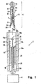
図1および2は、本発明に係る機能に本質的な穿刺システムの構成要素、すなわち使い捨て穿刺ユニット1と、その全体を図示していない穿刺装置2の部分とを示す。これらの部分は、特に図面に記号のみで表した穿刺駆動装置4と穿刺ユニット1の連結用のカップリング機構3を形成する。
1 and 2 show the components of the puncture system essential for the function according to the invention, ie the disposable puncture unit 1 and the part of the
穿刺ユニット1は2つの主構成要素、すなわち全体を6で表した針要素本体7と針8とを備える針要素ならびに皮膚接触面11から後方へ伸長し、針要素6の針要素本体7を囲む皮膚接触面11と基準要素本体12とを備える穿刺深さ基準要素10を有する。針8が図1および2aに示した利用位置にあるとき、その尖端13は好ましくは針尖端13を狭く取り囲み、かつそれによって穿刺ユニット1の支承中にその無菌状態を保証する樹脂材料からなる無菌保護部14によって取り囲まれている。
The puncture unit 1 extends rearward from a needle element comprising two main components, ie, a
図1および2aに穿刺ユニット1の納入状態が示されている。この状態で針要素6は固定手段15によって基準要素本体12内部の一定の長手位置に固定され、固定手段15(たとえば図示した嵌合凹所の中に係合するノブの形態)は、針要素6の相対的移動が穿刺深さ基準要素10に対して必要になるとき、この固定部が以下に説明する穿刺ユニットの挿入時(または後の穿刺運動中)に着脱されるように形成されている。
The delivery state of the puncture unit 1 is shown in FIGS. 1 and 2a. In this state, the
カップリング機構3は穿刺ユニット1の要素に対して分離されたカップリング、すなわち針要素カップリング16および基準要素カップリング17を有する。各カップリングは、要素の結合状態でそれらの各長手位置が少なくとも穿刺運動の転回点でストッパーの接触によって決定されるように、穿刺深さ基準要素10の針要素6もしくは10bの対応するストッパー6bと協働するストッパー16bもしくは17bを備える位置決め部16aもしくは17aを有する。
The
図示した場合において、針要素カップリング16の位置決め部16aは、針要素位置決め部16aが穿刺駆動装置4に接続された連結棒19の厚化頭部18によって形成される。この頭部18の前部の仕切面がストッパー16bを形成する。針要素6の対応するストッパー16bは図示した構造において針8の後端部によって形成される。針要素カップリングの図示した構造は、その他の情報を読み取ることができる米国特許第2004/0260325号から知られている。
In the illustrated case, the positioning
基準要素カップリング17の位置決め部17aとして円筒形の穴23の中に固定される摺動体22が用いられる。前記摺動体は対応する雄ねじ21を具備した連結棒19がねじ止めされた雌ねじ20を備える軸穴を有する。これらの構成要素によって形成された位置決め部16a、17aの相互の回転によって、それらの長手位置を互いに相対的に変化させることができる。好ましくは、この(ここでは摺動体22によって形成された)基準要素位置決め部17aが耐回動性かつ軸線方向移動可能に軸支されており、他方、この(ここでは位置決め棒19の頭部18によって形成された)針要素位置決め部16aが部材(ここでは連結棒19)と連結されており、その位置は基準要素位置決め部17aの内部で自軸周りの回転によって長手方向に変化させることができる。
A sliding
図1に二重矢印24によって表した前進段階および後退段階からなる穿刺運動時に、穿刺運動が正確に所定の穿刺方向に応じて行われることが保証される摺動体22および穴23がガイド部として作用する。
A sliding
基準要素カップリングは図示した場合において掛止鉤状体構造として形成されている。半径方向に弾性的に屈撓する基準要素本体12の後端部に掛止鉤状体25が形成されており、この鉤状体は穿刺ユニット1の挿入時に対応する摺動体22の前部正面側に形成された掛止形状26に係合する。ここでストッパー17bもしくは10bは摺動体22の前面もしくは基準要素本体12の最後端部によって形成されている。
In the illustrated case, the reference element coupling is formed as a latch-like structure. A hooking hook-
針要素カップリング16および基準要素カップリング17は全体的にそれぞれ1つの使い捨て穿刺ユニット1を交換可能に何度も使用できる穿刺装置2の穿刺駆動装置4と連結できる保持体27を形成する。保持体27への穿刺ユニット1の挿入は図2の部分図aおよびbに示されている。
The
より簡単な取扱いのために、穿刺ユニット1は挿入後に利用者によって回される、たとえばプラスチック射出成形法で射出された挿入補助部30を有する。挿入時に穿刺ユニット1は図2aに示した出発位置から図2bに示した位置へ運ばれ、そこで針要素カップリング16も基準要素カップリング17も閉鎖され、連結棒19と針要素本体7とのあいだもしくは摺動体22と基準要素本体12とのあいだに両軸線方向(双方向性)に作用する固定連結部を形成する。ここで針要素本体7の後端部に設けた収容部31は連結棒19の頭部18を取り囲む。掛止鉤状体25は対応する掛止形状26によって係止される。部分図aおよびbの比較から、穿刺深さ基準要素10に対する針要素6の相対運動によって無菌保護部14が針尖端13から離れて後方へ移動されたことが識別される。
For easier handling, the puncture unit 1 has an
ストッパー17bに対するストッパー16bの長手方向の間隔は、好ましくは穿刺ユニット1の挿入前に、針要素6が挿入過程中(固定遮断15を弛めて)、針尖端13が皮膚接触面11から出て、突出部が所望の穿刺深さに相当するまで前方へ移動されるように調整されている。しかしながら、穿刺深さが穿刺ユニットの挿入後に初めて調整される実施形態も可能である。いずれの場合も正確な所望の穿刺深さは位置決め部16a、17aの相対的長手位置の変化によって調整することができる。この調整が穿刺運動前に実施されるとき、針尖端13の突出部は皮膚接触面11に対して穿刺運動中に一定にとどまり、かつ穿刺ユニットの位置は穿刺運動の各時点で連結棒19の各位置によって決定される。
The distance in the longitudinal direction of the
図2cはフィンガーキャップ32の中へ穿刺する瞬間のシステム構成要素を示す。この場合、皮膚は内部へ(装置の主軸に対して)および後方へ円錐形に傾いた、穿刺箇所を取り囲むケース皮膚接触面33を有する。前記接触面は、この部分図に部分的に示した穿刺装置2の前端部に形成されている。このケース皮膚接触面33によって、穿刺駆動装置4と相対的に穿刺箇所の周囲で皮膚表面34の充分に限定された長手位置が保証される。穿刺深さは皮膚接触面11から針尖端13の間隔によって決定される。装置に固定された皮膚接触面33によって取り囲まれるケース開口部35は比較的大きいので、もちろん皮膚表面34はケース開口部35の中へ湾曲し、この前方湾曲の規模は様々な要因、特に皮膚の押圧力および弾力性に左右される。これが皮膚表面34の穿刺箇所の上記Z変数をもたらす。
FIG. 2 c shows the system components at the moment of puncturing into the
図2dは穿刺ユニットの取出し時のシステム構成要素を示す。このためにエジェクタが、たとえばここに図示した棒36の形態で設けられており、これは穿刺ユニット1の取出しのために図示しない駆動装置を利用して前方へ動かされる。この構造は、穿刺深さ基準要素10がまず前方へ移動されるように形成されており、他方、針要素6はまだ固定されている。要素6、10の相対的移動の発生によって針尖端13が保護されて穿刺深さ基準要素10の内部にくるまで、皮膚接触面11の後方へ戻される。それによって鋭い針尖端13と、それに伴う感染リスクとによる負傷の危険性が回避される。
FIG. 2d shows the system components upon removal of the puncture unit. For this purpose, an ejector is provided, for example in the form of a
図3および4は、皮膚表面の各位置への穿刺運動(様々な穿刺過程で可能なZ変数の範囲内)を補償するため、一般に38で表した行程補償を有する穿刺駆動装置4の2実施形態を示す。図1および2と一致して、カップリング機構3の両実施形態において、摺動体22の対応するねじ穴20の中に固定される雄ねじ21を備える連結棒19を有する。この場合もねじ付棒19の頭部18は針要素カップリングの位置決め部16aを形成し、他方、基準要素カップリングの位置決め部17aは摺動体22に形成されている。
FIGS. 3 and 4 show two implementations of the
針要素カップリングおよび基準要素カップリングの機械的構造原理も図1および2と一致する。位置決め部16a、17aは、図示しない針要素もしくは基準要素のカップリング領域で対応するカップリングプロフィールと協働する各々1つのカップリングプロフィールを有し、一方(好ましくは双方向性に作用する)は対応するストッパー要素を備えるカップリングが実現されている。
The mechanical structural principles of the needle element coupling and the reference element coupling are also consistent with FIGS. The
図1および2と異なり、図3および4に位置決め部17aが内部へ(連結棒19の軸上へ)向けた弾性アーム40の突出部39によって形成されている。対応する針要素に、外方へ開いた凹所または突出部39が係合する凹所が設けられている。
Unlike FIGS. 1 and 2, in FIGS. 3 and 4, the positioning
位置決め部16aおよび17aは、それぞれ1つの穿刺ユニットの交換可能の収容部への保持体27を形成する。連結棒19および摺動体22の相互の回転によって − 再び図1および2と一致して − 位置決め部16aおよび17aの長手位置が互いに相対的に変化され、それによって連結された穿刺ユニットの針突出部が調整される。保持体27と共に連結された穿刺ユニットの位置は、穿刺運動の各時点で連結棒19の各位置によって決定される。
図3に示した穿刺駆動装置4の駆動要素として(図示しない駆動ばねによっておよび同様に図示しないトリガ装置の解除後に駆動)、連結棒19の軸と一致するその縦軸周りの回転運動を実行する駆動ロータ41が利用される。駆動ロータ41の回転は制御曲線43および制御曲線摺動部44を含む曲線制御42により二重矢印24による並進穿刺運動に変換される。この種のロータ駆動装置は種々の出版物(たとえば引用した上記米国特許第5,318,584号)から知られているため、構造上の詳細な説明は不要である。
As a drive element of the
駆動ロータ41および曲線制御42は、駆動ロータ41の回転が穿刺運動に変換されるロータリスライドギヤ46を形成し、制御曲線摺動部44が制御曲線43の頂点43aを通過するとき、穿刺運動の転回点が達成される。ロータリスライドギヤ46は駆動要素(ロータ)の各位置と穿刺ユニットとのあいだの正確かつ一義的な割当てを保証する。この条件を満たす穿刺駆動装置を「強制ガイド式」と呼ぶ。
The
図示した実施形態において、このような強制ガイド式穿刺駆動装置は、弾性構成要素47によって行程補償と組み合わされる。図示した場合において、この弾性構成要素は、これが駆動ロータ41用の弾性軸受を形成するように形成かつ配置されたコイルばね48である。ロータ41は、穿刺運動時に保持体27と接続された穿刺ユニットの穿刺深さ基準要素の皮膚接触面が皮膚表面に当たるとき、前記ロータがコイルばね48の力に抗して後方へ移動できるようにガイド穴49の中に軸線方向に移動可能に軸支されている。この時点を「接触時点」と呼ぶ。
In the illustrated embodiment, such a forced guided puncture drive device is combined with stroke compensation by an
行程補償によって、この場合は弾性構成要素47の弾力性によって転回点の位置が皮膚表面のZ位置へ適合される。弾性ばね力は、弾性構成要素が穿刺運動中に接触時点前に本質的に変形されないように指定されなければならない。いずれにしても、接触時点の直前では実質的に変形してはならない。緩衝作用は初めて皮膚と皮膚接触面の接触時に発生しなければならない。
Due to the stroke compensation, in this case, the position of the turning point is adapted to the Z position of the skin surface by the elasticity of the
穿刺深さの調整のために調整つまみ51が用いられる。軸線方向に不動の調整つまみから軸線方向に移動可能の連結棒19へのモーメント伝達は、調整つまみ51の対応する内歯に係合する連結棒の縦歯52を用いて行うことができる。
An
基準要素位置決め部17a(と共に保持体27に固定された穿刺ユニット)のガイドのために、図示した場合に弾性アーム40の領域で位置決めされたケース穴53が用いられる。アーム40の必要な弾性可動性は、図示しない長手方向に延伸する溝によって保証されており、穴53の非円形断面形状によって軸線方向に移動可能の、但し耐回動性のガイドが保証される。
In order to guide the reference
図4に示した穿刺駆動装置4の実施形態の場合も、行程補償が弾性構成要素47によって達成される。この場合は2つのばね、すなわち駆動ばね54と、戻り行程ばね55とからなり、それぞれ一方でケース固定された軸受部56もしくは57に固定されており、他方では連結フランジ58を介して連結棒19に作用する。
In the case of the embodiment of the
図4にばね54および55の静止状態を示している。駆動装置を固定するために(図示しない手段を用いて)、たとえば連結フランジ58と協働するキャッチ60からなることができるトリガ要素59が係止するまで、連結棒19が下方へ移動される。固定時の連結棒19の移動は、本実施形態において連結棒19の端部に設けた縦歯52が調整つまみ51の対応する内歯に係合させ、その結果、調整つまみ51の回転によって保持体27に接続される穿刺ユニットの針尖端の突出部を調整することができる。
FIG. 4 shows the stationary state of the
トリガ要素59の解除後、連結棒19は駆動ばね54によって前方へ駆動される。駆動装置の弾性的構成によって接触時点の直後に穿刺運動の前進段階が終了する。部材の縦寸法は、皮膚表面の位置の全変数領域で駆動ばね54がその静止を越え出て回転され、もしくは保持体27に固定された穿刺ユニットの皮膚接触面が皮膚表面に当たるとき戻り行程ばね55がその静止位置を越え出て圧縮されるように選択されている。それに応じて接触時点の直後に穿刺運動の転回点が達成され、それに続き後退段階がこの状態で上回る戻り行程ばね55の力によって駆動される。
After the
図5は、摩擦カップリング95によって実現された行程補償を備える穿刺システムの4機能位置(a)〜(d)を示す。これは図示した場合において、そのアーム97が連結棒19に対して押圧する連結棒19とトング96からなる。連結棒19は本実施形態においても穿刺ユニット1に対する保持体27との接続部を形成する。針要素カップリング、基準要素カップリングおよび連結棒19の回転による針突出部の調整を含むそれらの構造は図1および2と一致する。
FIG. 5 shows the four functional positions (a) to (d) of the puncture system with stroke compensation realized by the
トング96および連結棒19は、穿刺運動の方向へ力の伝達を可能にする摩擦カップリング95の2カップリング要素を形成する。この力は「摩擦力Fr」と呼ばれ、かつ摩擦カップリングの要素間、つまりこの場合ではトング96および連結棒19のあいだの摩擦係数によって決定される。カップリング要素19、96のあいだに作用する力が摩擦力Frを上回るとき、穿刺運動の方向へ力伝達が中断されるように前記要素が互いに移動される。これは部分図(a)〜(c)によって具体的に示す:
− 穿刺運動の前進段階中(すなわち部分図(a)および(b)に示した機能位置のあいだ)に、摩擦力Frはこの運動段階で発生する力よりも大きく、その結果、要素19、95の相対的位置を変化しない。
− 部分図(b)は接触時点を示す。皮膚への穿刺深さ基準要素10の皮膚接触面の突き当りによって針要素のさらなる前進運動に必要な力が明らかに上昇し、前設定された摩擦力Frによって設定された限度値を超える。それによって必要な行程補償を可能にする摩擦カップリングの要素間の相対運動が生じる。図示した場合において、この行程は、皮膚接触時点(位置(b))とランセット駆動装置4の最大偏位(位置(c))とのあいだのトング96の位置の差に相当する量dzだけ短縮される。
− 穿刺運動の後退段階中、両カップリング要素の相対位置は、穿刺ユニット保持体のさらなる後退運動が好適な運動制限98によって停止されるまで不変の状態にとどまる。駆動装置4の引き続きの運動中、摩擦カップリング95の要素96、19の相対運動は、前記要素が再び出発位置にくるまで実施される。
The
During the advancement stage of the puncture movement (ie during the functional position shown in the partial views (a) and (b)), the frictional force F r is greater than the force generated in this movement stage, so that the
-Partial view (b) shows the point of contact. The force required for further forward movement of the needle element is clearly increased by the abutment of the skin contact surface of the skin puncture
-During the retraction phase of the lancing movement, the relative position of both coupling elements remains unchanged until further retraction movement of the lancing unit holder is stopped by a
この機能のために、摩擦力Frは一定の値を有する必要がある。この摩擦力は、これが穿刺運動中に接触時点前に発生する力の合計よりも大きくなるように指定しなければならない。これは本質的に参加した質量の移動に対する動的加速力および皮膚への侵襲に対する静的穿刺力である。他方、摩擦力Frは、穿刺深さ基準要素10が皮膚に対して押圧されるべきである最大の所望の力よりも小さくしなければならない。このような条件は常法の材料および製造方法によって調整できる。
For this function, the frictional force F r needs to have a constant value. This frictional force must be specified so that it is greater than the total force generated before the point of contact during the lancing movement. This is essentially a dynamic acceleration force for the mass movement involved and a static puncture force for skin invasion. On the other hand, the frictional force F r must be less than the maximum desired force that the puncture
図3〜5に示した行程補償の変形態様において、構成要素の弾力性によってのみもしくは標定制御なしの摩擦カップリングによってのみ皮膚表面の各Z位置へ適合される。それによって充分に快適な穿刺が達成されない場合、能動的に制御された行程補償を使用することができ、この能動制御は、たとえば機械的または電子的に実施できる皮膚表面の位置の検出に基づく。電子変形態様は、もちろん光電子検出法も含む。 In the stroke compensation variants shown in FIGS. 3-5, each Z position on the skin surface is adapted only by the elasticity of the components or by friction coupling without orientation control. If a sufficiently comfortable puncture is not achieved thereby, actively controlled stroke compensation can be used, this active control being based on detection of the position of the skin surface, which can be carried out mechanically or electronically, for example. The electronic deformation mode naturally includes a photoelectron detection method.
ここで穿刺運動の転回点の制御に関しては以下の基本原理に区別することができる:
a)ランセット運動の転回点の適応は、穿刺駆動装置が長手方向に移動され、それによって穿刺運動の転回点が皮膚表面の各位置と近似的に一致するように、皮膚表面からの穿刺駆動装置の間隔が調整されることによって、穿刺運動の開始前に実施することができる。この転回点は、理想的には皮膚接触時点での皮膚表面の位置よりも多少前方にあり、この小さい「行程残量」によって穿刺時の皮膚表面の弾性変形が考慮される。
Here, regarding the turning point control of the puncture movement, the following basic principles can be distinguished:
a) Adaptation of the turning point of the lancet motion is such that the puncture driving device is moved in the longitudinal direction, so that the turning point of the puncture motion approximately matches each position on the skin surface. By adjusting the interval, the puncture movement can be performed before the start. The turning point is ideally slightly ahead of the position of the skin surface at the time of skin contact, and elastic deformation of the skin surface at the time of puncture is taken into account by this small “remaining stroke amount”.
この実施形態において好ましくは、たとえば図3のロータ駆動装置を利用して説明したように、強制ガイド式ランセット駆動装置を使用することができる。穿刺運動の出発位置と転回点とのあいだの距離つまり行程の量は、その際不変である。行程補償は行程運動の長手方向移動によって行われる。 In this embodiment, a forced guide type lancet drive device can be preferably used as described with reference to the rotor drive device of FIG. The distance between the starting position of the puncture movement and the turning point, i.e. the amount of stroke, remains unchanged. The stroke compensation is performed by the longitudinal movement of the stroke motion.
この構造原理は特に正確な行程補償を可能とし、転回点の長手位置が皮膚の性質、特にその弾力性に左右されない。
b)皮膚表面の検出は接触時点でまたはその直前に穿刺運動中に実施でき、皮膚方向への加速が中断され、戻り行程が検出後に可能な限り短い時間的遅延で開始される。
This construction principle makes it possible to achieve particularly precise stroke compensation, and the longitudinal position of the turning point is independent of the nature of the skin, in particular its elasticity.
b) The detection of the skin surface can be carried out at the point of contact or just before the puncture movement, the acceleration towards the skin is interrupted and the return stroke is started with the shortest possible time delay after detection.
このような変形態様は構造的に比較的簡単にキー要素によって実現することができる。このキー要素は、好ましくは同様に穿刺運動の前進段階を終了し、かつ後退段階を開始する機械的制御要素(たとえばキャッチ)と協働する。もちろんこの関連性において、特に穿刺ユニットの前端部に電子センサを備えた電子変形態様も可能である。 Such a modification can be realized with key elements relatively easily in terms of structure. This key element preferably cooperates with a mechanical control element (eg catch) that likewise ends the advancement phase of the lancing movement and starts the retraction phase. Of course, in this connection, an electronic deformation mode in which an electronic sensor is provided at the front end of the puncture unit is also possible.
この構造原理では、a)と異なり穿刺運動の行程が皮膚表面の位置に依存する。皮膚表面が穿刺駆動装置に近すぎると、前進段階がさらに早く終了し、後退段階が開始される。すなわち行程がさらに小さくなる。 In this structure principle, unlike a), the stroke of the puncture movement depends on the position of the skin surface. If the skin surface is too close to the puncture drive device, the advancement phase ends more quickly and the retraction phase is started. That is, the stroke is further reduced.
図6および7ないし9は、手動利用に好適であり、さらに穿刺システムの構成要素として使用できる本発明に係る穿刺ユニットの2変形態様を示す。この場合は穿刺深さ基準要素10の長手位置が穿刺方向(これは針の方位に相当する)における針要素6と相対的に穿刺ユニットなしでも変化させることができ、針要素6が設定された位置に固定される手段がある。
6 and 7 to 9 show two variants of the puncture unit according to the invention which are suitable for manual use and can be used as a component of the puncture system. In this case, the longitudinal position of the puncture
図6に示した実施形態において、針要素6の針要素本体7および基準要素本体12が対応するねじを有し、このねじは、その相対的長手位置と共にランセット尖端13の相対的長手位置が皮膚接触面11と相対的に相互の回転によって変化可能に形成かつ配置されている。針尖端13を無菌保護部14内部の示した静止位置に前記無菌保護部が皮膚接触面11に対して突出する利用位置へ移動させるために、針要素6の針要素本体7が針要素本体7の好適な係合形状62に噛み合う工具を利用して回される。これは手動で行うことができる。好ましくは図6に示した穿刺ユニットは穿刺装置と組合せて使用され、穿刺深さの調整はこの場合も穿刺の中へ挿入する前に手動でまたは穿刺装置の内部で実施することができる。
In the embodiment shown in FIG. 6, the
図7に示した変形態様では、針要素6の針要素本体7の後端部に、穿刺ユニット収容部65の対応する多段支持形状64と協働する支持形状63が設けられている。断面の支持形状すなわち円弧としての可能な形成は図8および9から識別される。
In the modification shown in FIG. 7, a
穿刺深さ基準要素10は、この場合、針要素の針要素本体7の前部分を取り囲むキャップ66によって形成される。キャップ66は針要素本体7上に摩擦係合式に固定されている。出発状態で図7に別々に分けて記載した挿入補助具30が針8の上方に固定される。この補助具は針尖端13を保護し、所望の穿刺深さに相当する穿刺ユニット収容部65の中への回転位置で穿刺ユニット1を挿入することに用いられる。挿入時にキャップ66は、その下角部67が穿刺ユニット収容部65の上角部68に接触するとき、針8と相対的に前方へ移動される。それによって針尖端13の突出部は皮膚接触面11に対して調整される。挿入後に挿入補助具30が回され、その結果、針8は利用に提供される。
The puncture
穿刺ユニットなしでも使用できる多数のその他の本発明に係る穿刺ユニットの変形態様が可能である。この場合、一般的に基準要素本体が皮膚接触面から後方へ延伸し、少なくとも針要素の長手位置が穿刺深さ基準要素と相対的に基準要素本体と針要素の本体部とのあいだの接触によって固定されるように、針要素の本体部に係合する場合に有利である。この接触は少なくとも摩擦係合式(図7のように)にしなければならない。基準要素本体の内部の針要素の形状嵌合式固定(図6のように)は、多くの適用目的に対して特に有利である。 Many other variations of the puncture unit according to the present invention are possible that can be used without the puncture unit. In this case, generally, the reference element body extends backward from the skin contact surface, and at least the longitudinal position of the needle element is caused by contact between the reference element body and the needle element body portion relative to the puncture depth reference element. It is advantageous when engaged with the body of the needle element to be fixed. This contact must be at least frictionally engaged (as in FIG. 7). The shape-fitting fixation (as in FIG. 6) of the needle element inside the reference element body is particularly advantageous for many application purposes.
図10ないし13は、まず針要素6の針8が毛細管路70を有し、この毛細管路の内径によって体液が針要素6のサンプル収容領域71の中に流れ込むことができることによって前述の穿刺ユニットから区別される穿刺ユニットを示す。それによって針要素6は、冒頭に述べた形式のマイクロサンプラーである。サンプル収容領域71の中に(針要素6の針要素本体7の内部に)分析手段が配置されている。
10-13, first the
この実施形態の場合も、穿刺深さの調整は、穿刺深さ基準要素10の皮膚接触面11からの針尖端13の間隔は針要素カップリング(16)および基準要素カップリング(17)の構成要素である位置決め部(16a、17a)を利用して調整されることに基づく。
Also in this embodiment, the puncture depth is adjusted by adjusting the distance between the
針要素位置決め部16aはこの場合2アーム型グリップ73として形成されており、これらの内方へ向くアームは弾性的であり、かつ針要素カップリング16が閉鎖されるとき、針要素6の針要素本体7の対応する凹所75の中に係合する突出部74を有する。針要素カップリング16の閉鎖状態において針要素位置決め部16aの長手位置は図示した場合において一方でグリップ73の内部仕切面によって、かつ他方では針要素本体7の後正面によって形成される2つのストッパー16b、6bの協働によって決定される。この針要素カップリングも双方向性に作用し、つまり穿刺運動の両運動方向へ針要素6と位置決め部16aが結合している。
The needle
穿刺深さ基準要素10の基準要素本体12は本質的に開いたフレーム77からなり、このフレーム下側に皮膚接触面11が形成されており、長手方向に対して横に延伸する針要素6に係合するプロフィール部78である。皮膚接触面は針要素6の針8用の開口部69を取り囲む。
The
この例は、基準要素本体が閉鎖された部材であってはならないことを示している。むしろ、前記基準要素本体が本発明の枠組みの中で必要な機能を満たす限り、開いた構造も好適である。これには特に、両部材の相対運動が針突出部dの調整に対して長手方向に可能であるように、針要素6が基準要素10に接続されていることも含む。さらに、針要素6と基準要素7とのあいだの接続は長手方向への良好な案内を生ぜしめる必要があり、その結果、穿刺方向と異なる空間方向への両部材の運動が阻止される。
This example shows that the reference element body must not be a closed member. Rather, an open structure is also suitable as long as the reference element body fulfills the necessary functions within the framework of the present invention. This includes in particular that the
ストッパー17bを備える基準要素カップリング17の位置決め部17aは、軸線方向に導かれるが耐回動性の軸受部80に固定されている。対応するストッパー10bは、フレーム77の後正面によって形成される。この場合は、非双方向性に作用するカップリングである。すなわち、ストッパー17b、10bの協働は後退段階中ではなく、穿刺運動の前進段階中(図10および11で下方へ)のみの穿刺深さ基準要素10の相対的長手位置を決定する。
The
図1〜4の場合と同様に、ランセット駆動装置4は連結棒19を介してカップリング16、17によって形成された穿刺ユニット保持体27に接続され、位置決め部16、17の相対的長手位置は、連結棒19(これに基準要素位置決め部16aが固定されている)が基準要素位置決め部17a(ここでは軸受部80)の内部でその自軸周りに回転することによって移動可能であることにより調整可能である。
As in the case of FIGS. 1 to 4, the
グリップ73は連結棒19の端部に回動可能に軸支されており、前記グリップ73が連結棒19の回転位置に関係なく図10に示した係合位置にとどまるように穿刺ユニット内に導かれる。グリップ73の突出部74および対応する凹所75の領域で、電気コンタクトを設けることができ、それによって穿刺ユニット6が電気化学マイクロサンプラーとして形成されている場合、サンプル収容領域にある試薬で電気測定を実施することができる。選択肢としてサンプル収容領域71の内部に、測光分析で作動するマイクロサンプラーの場合に必要な場合測光法の測定を可能にするために窓79を設けることができる。この測定原理は公知であるため、より詳しい説明は不要である。
The
図14はマイクロサンプラー穿刺ユニットの4利用段階(a)〜(d)を示しており、それらの構造上の特徴は図10〜13に相当する;
− 部分図(a)は、針要素6が摩擦係合式に一定の長手位置に基準要素10と相対的に固定されている納入状態を示す。この固定は、針要素6の本体部7の仕切面に対して押圧する基準要素10でのノブ82によって達成される。
− 部分図(b)は、比較的少ない針突出部d、つまり比較的小さい穿刺深さを有する穿刺の場合に対する穿刺運動の転回点での状態を示す。状態(a)から状態(b)への運動時に、まず針要素カップリング16(図10および11)が閉じられており、かつ針要素6が下方へ押圧され、ストッパー16b、6bが互いに密着する。前進段階中の後の時点でストッパー10b、17b間の接触が生じ、その結果、基準要素10が皮膚の方向へ移動される。この運動経過は、穿刺深さの調整が穿刺運動の開始前に行う必要がなく、その前進段階中に行ってもよいことの一例である。針8は皮膚の中に侵入し、皮膚接触面11が皮膚に密着されるとき終了される。
− 部分図(c)は、同様に穿刺運動の転回点での利用状態を示すが、最大針突出部d、つまり最大穿刺深さの場合である。
− 充分なサンプル量が針要素6のサンプル収容領域71へ流れたとき、穿刺運動の後退段階が開始され、かつ針要素は基準要素の内部に引き込まれる。その際、基準要素は図示しない手段によって固定される。針要素6は部分図(d)に示した位置に到達し、そこで針8が負傷リスクから保護するために皮膚接触面11の後方へ引き込まれている。この位置で針要素6の針要素本体7は遮断突出部83の後方に固定され、前記突出部は、針要素6がそれ以上利用位置(図bもしくはc)へ戻ることができないように形成されている。基準要素本体12および/または針要素6に設けることができるこの種の遮断手段によって、穿刺ユニット1の利用後、利用された穿刺ユニット1の再利用が確実に阻止されるように基準要素10と相対的に針要素6の運動が制限される。
FIG. 14 shows the four stages of use (a) to (d) of the microsampler puncture unit, whose structural features correspond to FIGS. 10 to 13;
-Partial view (a) shows the delivery state in which the
Partial view (b) shows the state at the turning point of the puncture movement for the case of a puncture with a relatively small needle protrusion d, ie a puncture with a relatively small puncture depth. During the movement from the state (a) to the state (b), the needle element coupling 16 (FIGS. 10 and 11) is first closed, the
-Partial view (c) shows the use state at the turning point of the puncture movement in the same way, but in the case of the maximum needle protrusion d, that is, the maximum puncture depth.
-When a sufficient sample volume has flowed into the
穿刺運動の経過はマイクロサンプラー(図10〜14)の場合ランセット(図1〜9)の典型的な穿刺運動から区別される。ランセットの場合に穿刺運動の後退段階が転回点に到達した直後に行われ、穿刺運動は全体的に可能な限り速く経過するべきであり、他方、マイクロサンプラーの場合に後退段階中の穿刺ユニットの運動が体液の吸引に必要な時間だけ転回点に到達後に中断または遅延される。対応する経路時間線図は図15に示している。前進段階V中の穿刺方向への急速な運動に相当する急峻な上昇が識別される。穿刺運動の転回点に相当する極大Mに達した後、図示した好ましい実施形態において、初めに短くかつ速い、次にゆるやかな後退運動R2へ移行する後退運動R1が続く。R1で表した後退段階の区間は、皮膚組織の内部に針尖端の手前の領域で試液が収集される小さい自由空間を形成することに利用される。それに続き区間R2のあいだに血液がマイクロサンプラーの毛細管路を通りそのサンプル収容領域へ流れる。この過程が終了したとき、針が皮膚組織から引き抜かれる後退段階の区間R3がつづく。 The course of the puncture movement is distinguished from the typical puncture movement of the lancet (FIGS. 1-9) in the case of a microsampler (FIGS. 10-14). In the case of a lancet, the retraction phase of the puncture movement should take place immediately after reaching the turning point, and the puncture movement should be as fast as possible overall, whereas in the case of a microsampler, The exercise is interrupted or delayed after reaching the turning point for the time required to draw the body fluid. The corresponding path time diagram is shown in FIG. A steep rise corresponding to a rapid movement in the puncture direction during the advance phase V is identified. After reaching the maximum M, which corresponds to the turning point of the puncture movement, in the illustrated preferred embodiment, there follows a backward movement R1 which first shifts to a short and fast and then to a gentle backward movement R2. The interval of the receding stage represented by R1 is used to form a small free space in the skin tissue in which the reagent solution is collected in a region before the needle tip. Subsequently, blood flows through the capillary passage of the microsampler to its sample receiving area during the section R2. When this process is finished, a retraction stage R3 in which the needle is withdrawn from the skin tissue follows.
この種のマイクロサンプラーに好適な運動経過は様々な方式で実現できる。特に前進段階Vおよび後退段階R1の第1区間に対して機械式ばね駆動が好適であり、他方、比較的遅くかつコントロールされた運動が区間R2およびR3中に好ましくは電気モータを用いて駆動される。 The movement course suitable for this type of microsampler can be realized in various ways. Mechanical spring drive is particularly suitable for the first section of the forward phase V and the reverse phase R1, while the relatively slow and controlled movement is preferably driven by means of electric motors during the sections R2 and R3. The
図16および17は、多数の穿刺ユニットが1つのマガジンの中にまとめられ、かつ穿刺装置の内部で順々に穿刺位置へ搬送される穿刺システムにも本発明を使用できることを具示するものである。それに対して好適な米国特許第6,616,616号から公知の構造は、図16に示している。この場合、ランセット状の穿刺ユニット1はプラスチック製のマガジンストリップ85の中にあり、その中に前記穿刺ユニットが軸線方向に移動可能かつ導出されるように保持されている。前記穿刺ユニットはその後端部にカップリングシリンダ86を有する。前記カップリングシリンダは、静止位置87にあるランセットを、図示しない穿刺駆動装置との接続を構築するカップリング機構3と連結することに利用される。
FIGS. 16 and 17 illustrate that the present invention can also be used in a puncture system in which a number of puncture units are grouped in one magazine and transported sequentially to the puncture position within the puncture device. is there. A suitable structure known from US Pat. No. 6,616,616 is shown in FIG. In this case, the lancet-like puncture unit 1 is in a plastic magazine strip 85, in which the puncture unit is held so as to be movable and led out in the axial direction. The puncture unit has a
図17は、本発明をマガジン化穿刺ユニットを備える穿刺システムで実現するために好適である変形態様を具示する。図示しない穿刺駆動装置によって発生された穿刺運動の伝達は、マガジンストリップ85と相対的に穿刺運動24を実行する連結棒19を用いて行われる。カップリングシリンダ86はこの実施形態において針要素6の針要素本体7を形成する。連結棒19は固定ねじ89がねじ止めされた軸受部88に作用する。軸受部88および皮膚接触面11を備える穿刺深さ基準要素10はガイド棒90、91によって穿刺運動方向へ案内される。
FIG. 17 shows a modification that is suitable for realizing the present invention in a puncture system including a magazine-based puncture unit. Transmission of the puncture motion generated by a puncture drive device (not shown) is performed using the connecting
この構造において基準要素カップリング16の位置決め部16aは軸受部88によって形成される。軸受部88にあるカップリングシリンダを収容する凹所92の後部底面は、この場合に針要素6の針8の後端部によって形成される対応するストッパー6bと協働するストッパー16b、6bを形成する。
In this structure, the positioning
基準要素カップリング17はこの実施形態で非双方向性に作用する。その位置決め部17aは固定ねじ89によって形成され、それらの前正面は、穿刺深さ基準要素10の対応するストッパー10bと協働する基準要素カップリングの基準要素カップリングのストッパー17bとして作用する。
The
穿刺運動の前進段階で連結棒19が前方(図17上方へ)へ移動されるとき、初めに針尖端13が皮膚接触面11によって取り囲まれる開口部69から突出するまで、針要素6が穿刺方向へ移動される。その際に生じる突出部は、固定ねじ89すなわちそれに形成されたストッパー17bの長手位置によって基準要素のストッパー10bと相対的に決定される。この両ストッパーの接触時に基準要素が戻りばね93の力に抗して、その深さが皮膚接触面11に対する針尖端13の突出部によって決定される穿刺が実施されるまで、針要素6と同期して連動される。
When the connecting
構成要素88、89および10は、この態様においてマガジンの構成要素であるが、これらは各マガジンに1回だけ設けられる。この要素は、択一的に穿刺装置の構成要素として実現することもできる。いずれにしても本発明に係るマガジン化穿刺ユニットを備える穿刺システムにおいてマガジンの全穿刺ユニットに対してただ1つ(共通)の穿刺深さ基準要素が設けられている場合に有利である。その際に、搬送運動は穿刺過程のあいだで実施され、それによって各々1つの新規の針要素6が(図17に示した)位置へ持ち込まれ、その中で前記針要素は、所望の穿刺深さを保証するために、少なくとも穿刺運動の一部のあいだで針要素と共に移動される。
本発明は様々なマガジン構造と組み合わせて使用することができる。これには特に、たとえば前記米国特許第2004/0260325号に記載されているようなドラムマガジンも含まれる。 The present invention can be used in combination with various magazine structures. This includes, in particular, drum magazines as described, for example, in the aforementioned US 2004/0260325.
図18および19に示した穿刺システムにおいて、穿刺ユニット1の構成およびその穿刺駆動装置4との接続は広範囲に図1および2と一致する。穿刺ユニット1は針8を備える針要素6と、針を取り囲むプラスチック製の針要素本体7と、この場合においてスリーブ状の基準要素本体12および皮膚接触面11を備える穿刺深さ基準要素10とからなる。
In the puncture system shown in FIGS. 18 and 19, the configuration of the puncture unit 1 and its connection with the
ランセット駆動装置4との連結は、針要素カップリング16および基準要素カップリング17を含むカップリング機構3を利用して構築される。図1および2と一致して、針要素カップリング16の針要素位置決め部16aは針要素本体7の対応する収容部31に係合する連結棒19の頭部18によって形成される。基準要素カップリングは、この場合も掛止鉤状体25および掛止形状26からなる掛止カップリングを利用して構成されており、この掛止カップリングは穿刺深さ基準要素10もしくは長手方向に連結棒19上で移動可能に案内された基準要素保持体100に形成されている。
The connection with the
図18および19の穿刺システムは(その限りで図4と一致する)、穿刺運動が上記の意味において強制案内されない、いわゆる「バリスティック型」穿刺駆動装置4を有する。バリスティック型穿刺駆動装置の場合、穿刺運動が少なくとも転回点の周囲に、好ましくは全運動経路上に1つまたは複数の駆動ばねの加速力、この駆動ばねによって加速された部材および運動を制御または制限するストッパーの慣性モーメント(ならびにもちろん移動する部材間の摩擦)によってのみ決定されている。
The puncture system of FIGS. 18 and 19 (to that extent coincides with FIG. 4) has a so-called “ballistic”
駆動ばね54として、図示した場合において、図に圧縮状態で示したコイルばねが用いられる。このコイルばねは、トリガ要素59が作動されると、直ちに駆動ばね54によって穿刺方向へ加速される連結棒19と連結されている。図示した実施形態の場合、トリガ要素59は図示した保持位置で連結棒19を固定する閂123である。閂123は、穿刺運動の解除のために、連結棒19が駆動ばね54によって加速できるように引き戻される。
In the illustrated case, a coil spring shown in a compressed state in the figure is used as the
基準要素カップリング17は穿刺ユニット1の挿入時に閉鎖される。逆に針要素カップリング16は連結棒19が前方へ移動される場合に始めてトリガ要素の作動後に閉鎖される。この時点から針要素6の移動も穿刺深さ基準要素10の移動も正確に対応する針要素位置決め部16a、17aに、すなわち連結棒19もしくは基準要素保持体100の移動に続く。
The
後続の前進段階中、連結棒19は、基準要素保持体100の後端部に形成された調整装置126の対応するストッパー面125をストッパー面101と接触するまで前記連結棒を前方へ移動させる。ストッパー面125は、穿刺方向に伸長するねじ128上にねじ止めされる調整ねじ127の頭部にある。調整ねじ127の回転によってストッパー面125の長手位置は基準要素10(それによって皮膚接触面11)と相対的に調整することができる。
During the subsequent advancement phase, the connecting
従って、図示した好ましい実施形態において、穿刺駆動装置4は直接針要素6とのみ連結されており、他方、基準要素10は穿刺運動の前進段階で作用する連動装置を介して針要素6と、かつそれによって間接的に穿刺駆動装置4と連結されている。全体を103で表した連動装置の構成要素は、その相対的間隔が針尖端13の長手位置を穿刺深さ基準要素10の接触面11と相対的にかつそれによって穿刺深さを限定するように、さらなる前進段階中に穿刺運動の転回点に到達するまで互いに密着するストッパー101および125である。従って、このストッパー101、125は穿刺深さ制限ストッパーと呼ばれる。
Thus, in the preferred embodiment shown, the
転回点の到達時に駆動ばね54が伸び、その結果、連結棒19が再び引き戻され、それによって穿刺運動の後退段階が始まる。つまり図示した場合では、駆動ばね54のばね力は穿刺運動の前進段階中でも後退段階中でも穿刺ユニットの加速に利用される。
When the turning point is reached, the
図示した穿刺システムの好ましい機能に対しては、基準要素10が前進段階の一部のあいだおよび特に好ましくは(さらに後述するように)後退段階の一部のあいだでも基底部146を利用して基準要素軸受105上に静止する。ここで基底部とは、直接的または間接的に基準要素10と連結され、かつその後方への運動経路が基準要素軸受と協働して一定の位置に制限する機能要素である。図示した構成において、基準要素保持体100と連結され、かつ機能については後述する針要素戻り止め138に形成された肩部によって形成される。
For the preferred function of the puncture system shown, the
ここに図示した実施形態において、基準要素軸受105の位置はその他の部材の寸法を考慮に入れて、基準要素ストッパー101、125の接触が穿刺運動の転回点の直前で初めて実施されるように選択され、その結果、基準要素保持体100が転回点に到達するまで僅かにのみ基準要素軸受105から持ち上げられる。基準要素10が自由に穿刺方向に移動できる(つまり特にその運動経路内にある本体部に突き当たらない)場合でさえ、図21Bに示した、基底部146が基準要素軸受105から持ち上げられる最大行程dhは最大5mm、好ましくは最大3.5mmおよび特に好ましくは最大2mmになる。
In the illustrated embodiment, the position of the reference element bearing 105 is selected so that the contact of the
後退段階の始めに基準要素10は針要素6と共に基底部146が基準要素軸受105から持ち上げられた短区間dh分だけ後方へ移動される。この後方運動は一方で皮膚接触面11が密着する皮膚表面の弾力性によって、かつ他方では連結棒19および針要素6の後方運動によって生ぜしめられ、前記要素と穿刺深さ基準要素10もしくは基準要素保持体100とのあいだの摩擦が充分な力伝達を生ぜしめる。
At the beginning of the retraction phase, the
基準要素軸受105によって基準要素保持体100と共に穿刺深さ基準要素10のさらなる後方運動が停止され、他方、連結棒19と共に針要素6は、ばね54の力によって前記針要素戻り止め138の遮断要素137によって運動が止められるまで、さらに後方へ引っ張られる。図示した場合において針要素戻り止め138は、その自由端にキャッチとして形成された遮断要素137を担持するばねアームの形態のばね要素139を含む。このキャッチは、穿刺運動の前進段階中に、連結棒19に配置された掛止突出部142に形成された対応する摺動面141を提供する面取りされた摺動面140を有する。この通過摺動中、遮断要素137のばねアーム139は弾性的に側方へ屈撓する。掛止突出部142が遮断要素137を通過すると、直ちにこの掛止突出部142は、ばねアーム139によって取り込まれたばね力のために再びその元の位置へ戻り、そこで連結棒19と共に針要素6を停止し、その際に連結棒19の掛止突出部142のストッパー面143が遮断要素137のストッパー面144と衝突する。
Further backward movement of the puncture
針要素戻り止め138は構造的に別様に構成することもできる。一般に、基本的に穿刺ユニット6の後退運動を一定の長手位置で停止できるあらゆる要素が好適である。この長手位置は、好ましくは針8の尖端13が皮膚接触面11の平面に対して一定の残穿刺深さ分だけ突出するように、前記長手位置が基準要素軸受105によって設定された皮膚接触面11の長手位置と相対的に選択されている。
図18および19は穿刺駆動装置4と穿刺ユニット1とのあいだのカップリング機構3の構成要素としてまったく異なるカップリングタイプが使用されることを具示する。針要素カップリング18は穿刺運動の前進段階中に穿刺駆動装置4を針要素6と連結し、かつそれによって前記要素間に双方向性に作用する固定連結を形成する。穿刺駆動装置4と基準要素6とのあいだの連結は、間接的に基準要素保持体100を介して構築される。これは一方で穿刺ユニット1の挿入時に双方向に作用する基準要素カップリング17によって基準要素10に固定連結される。他方、基準要素保持体100は、連結棒19およびそれと共に針要素6がストッパー125および144のあいだの区間Δdを介して基準要素と相対的に移動可能であるように形成された、一方向に作用する(非双方向性)各々1つのカップリングを形成する2組のストッパー125、101および143、144を含む連動装置103の構成要素である。Δdは、好ましくは、以下、さらに詳しく説明するように、最大穿刺深さdmと残穿刺深さdrとのあいだの差を形成する。
18 and 19 show that a completely different coupling type is used as a component of the
図18および19の構造によって図20に経路時間線図の形態(「穿刺特性」)で図示した穿刺運動を実現することができ、この運動は特にマイクロサンプラー穿刺システムに対して、一般的にその針要素がサンプルを収容する毛細管路を有する穿刺システムに好適である。図21は、図18および19の穿刺システムと広範囲に一致する穿刺システムの4利用位置を示し、いくつかの構造要素を簡素化された。利用位置A〜Dに相当する時点は図20でこれらのアルファベットでマークしている。 The structure of FIGS. 18 and 19 can achieve the puncture movement illustrated in FIG. 20 in the form of a path time diagram (“Puncture Characteristics”), which is generally the case for microsampler puncture systems. The needle element is suitable for a puncture system having a capillary channel containing a sample. FIG. 21 shows the four utilization positions of the puncture system that are broadly consistent with the puncture system of FIGS. 18 and 19, with some structural elements simplified. Time points corresponding to the use positions A to D are marked with these alphabets in FIG.
図20に前進段階Vおよび後退段階R中の針要素の針突出部dの時間的経過を示しており、後退段階Rは第1後退区間R1、収集区間Sおよび第2後退区間R2からなる。時間軸は不均一に分割されている。T1で表した運動区間は実質的に数ミリ秒の範囲内で経過し、他方、T2で表した運動区間(収集区間の手前の制動)は数100ミリ秒かかり、収集区間(T3)は数秒かかる。 FIG. 20 shows the time course of the needle protrusion d of the needle element during the forward stage V and the backward stage R, and the backward stage R includes a first backward section R1, a collection section S, and a second backward section R2. The time axis is divided unevenly. The movement section represented by T 1 substantially lapses within a range of several milliseconds, while the movement section represented by T 2 (braking before the collection section) takes several hundred milliseconds and the collection section (T 3 ) Takes a few seconds.
前進段階V(利用位置B)の終了時、穿刺要素は穿刺装置の調整後典型的に0.8mm〜2.3mmになる最大穿刺深さdmに達する。これに、穿刺要素が後退区間Δd分だけ部分的に引き戻され、終わり頃に制動される第1後退区間R1が続き、その結果、たとえば0.5mmの所定の残穿刺深さdrで皮膚中に入る(利用位置C)。最後に、針要素6の針8が完全に皮膚から引き出される第2後退区間R2(利用位置D)が続く。
At the end of the forward phase V (use position B), the puncture element reaches a maximum puncture depth dm which is typically between 0.8 mm and 2.3 mm after adjustment of the puncture device. This is followed by a first retraction section R1 in which the puncture element is partially retracted by a retraction section Δd and is braked towards the end, so that, for example, a predetermined residual puncture depth dr of 0.5 mm enters the skin. Enter (use position C). Finally, the second retraction section R2 (use position D) in which the
図19、20および21に示した構造において、第2後退区間R2は収集段階の終了時、遮断閂145が図19および21A〜21Cに示した係合位置から図21Dに示した後退位置へ引っ張られることによって開始され、その結果、戻り止め138は連結棒19と共に駆動ばね54によって後方へ移動される。それによって後退段階が終了し、かつ針要素6の針8が完全に皮膚から取り除かれる。
In the structure shown in FIGS. 19, 20 and 21, the second retracting section R <b> 2 is pulled from the engagement position shown in FIGS. 19 and 21 </ b> A to 21 </ b> C to the retracted position shown in FIG. As a result, the
図15および20に示された穿刺特性を比較すると、第1の相違点は、残穿刺深さdrが後退段階の収集区間S中実質的に変化せず、− 図18〜21に示した構造において基準要素軸受105および針要素戻り止め138の協働によって − 一定に設定されていることにある。しかし特に重要であるのは、最大穿刺深さdmが残穿刺深さdrに関係なく調整できることである。その限りにおいて図18〜21の穿刺システムは穿刺深さの調整が全穿刺運動に影響し、そのためサンプルがマイクロサンプラーの中に収容される残穿刺深さdrが、最大穿刺深さdmを設定するとき必然的に変化する上記穿刺システムから区別される。
Comparing the puncture characteristics shown in FIGS. 15 and 20, the first difference is that the remaining puncture depth dr does not substantially change during the collection section S in the receding stage, and the structure shown in FIGS. In reference to the reference element bearing 105 and the
本発明の枠組みの中で、マイクロサンプラー穿刺システムの利用時のサンプル採取の品質および痛み感覚に対して、針要素の針がサンプルの収集中に皮膚の中に入る、ここで残穿刺深さとして表した穿刺深さが調整された最大穿刺深さに関係なく近似的に一定であるとき、非常に有利であることが確認された。残穿刺深さの少ない変動またはサンプル収容中の針要素のゆるやかな運動は受け入れることができる。しかしながら、最大穿刺深さdmはサンプルの収容中の残穿刺深さの時間平均に左右されずに調整できる。 Within the framework of the present invention, for sample collection quality and pain sensation when using a microsampler puncture system, the needle of the needle element enters the skin during sample collection, where the remaining puncture depth is It has been found that it is very advantageous when the expressed puncture depth is approximately constant regardless of the adjusted maximum puncture depth. Variations in the residual puncture depth or gradual movement of the needle element during sample storage are acceptable. However, the maximum puncture depth dm can be adjusted without being influenced by the time average of the remaining puncture depth during sample accommodation.
穿刺特性が図20を利用して説明する特殊性で実現される穿刺システムのもう1つの実施例は図22に側面図で、図23に断面図でかつ図24で透視斜視図で示されている。 Another embodiment of the puncture system in which the puncture characteristics are realized with the particularity described with reference to FIG. 20 is shown in a side view in FIG. 22, in a sectional view in FIG. 23 and in a perspective perspective view in FIG. Yes.
穿刺ユニット1およびカップリング16および17の構成は図18および19と一致する。従って、ここでも同じ符号で表している前記要素およびそれらの機能は、再度記載しない。
それに対して、穿刺駆動装置4は本質的に図18および19から区別される。これは、以下詳しく説明する行程補償によるロータ駆動装置である。
The configurations of the puncture unit 1 and the
In contrast, the
図示した穿刺装置2の穿刺駆動装置4には、駆動ばね201、駆動ばねを緊定する固定ロータ202および駆動ばね201によって駆動される駆動ロータ203が含まれる。駆動ロータ203の回転運動は制御装置を利用し曲線制御の形態で針要素6の穿刺運動に変換される。針要素制御曲線205は溝として駆動ロータ203の中に形成されており、針要素制御曲線摺動部206(制御曲線205に係合するピンの形態で)から出発し、これは針要素6が連結されている連結棒19に連結されている。
The
穿刺深さ基準要素10の運動は、基準制御曲線212と基準制御曲線摺動部213とからなる曲線制御によって制御される。制御曲線212は同様に駆動ロータ203の中の溝として形成されている。制御曲線212に基準要素保持体100に連結された制御曲線摺動部213が係合する。
The movement of the puncture
穿刺深さの調整のために両方の針要素制御曲線205および212の間隔は調整可能の軸線支承の形態で調整装置214を利用して調整可能である。両方の針要素制御曲線205および212は、駆動ロータ203の第1部分203aもしくは駆動ロータ203の第2部分203b上に配置されている。調整装置214を利用して駆動ロータ203の第1部分203aと第2部分203bとのあいだの間隔を変化させることができる。
For adjustment of the puncture depth, the distance between both needle element control curves 205 and 212 can be adjusted using the
利用時に穿刺装置が図21に模式的に暗示した、ケース開口部35を取り囲むケース皮膚接触面33と共に利用者の皮膚表面に押圧される。それに続き(能動的)行程補償のために皮膚表面の基準要素10の間隔が決定される。それに対して電気モータ220を利用して穿刺装置へ移動可能の第1スキッド221が皮膚表面へ近づけられる。第1スキッド221上に、連結棒19によって形成された針要素位置決め部16aおよび基準要素保持体100によって形成された位置決め部17aを含む穿刺駆動装置4が軸支される。スキッド221は基準要素10が皮膚に接触するまで前方へ移動される。これは電子的に、たとえば誘導性または容量性測定によって決定することができる。それに続きスキッド221は皮膚表面に対する一定の間隔が生じるまで再び多少引き戻される。
At the time of use, the puncture device is pressed against the skin surface of the user together with the case
穿刺運動の解除後、針要素位置決め部16aおよび基準要素位置決め部17aは穿刺運動の前進段階中、対応する曲線制御205,212の立上りエッジによって前方へ移動される。皮膚表面への針要素6の針8の侵入中、基準要素10はその皮膚接触面11と共に前記皮膚接触面に密着され、その結果、正確な穿刺深さに対する基準点が限定されている。
After the puncturing movement is released, the needle
Z変数の補償のために、この態様においても行程補償38が設けられており、ここでさらに2つの行程補償構造が組み合わせて使用される。
− 一方で皮膚表面の位置が穿刺運動の解除前に検出され、かつ後続の穿刺運動が事前に検出された位置(この場合は全行程区間の移動によって)適合されることによって実現されている。この能動的行程補償の形態は図示した態様だけではなく、別の構造上の実現にも有利である。
− さらに、この場合に第1スキッド221が長手方向に移動可能に押圧制御ばね223の力に抗して押し戻すことができる第2スキッド222上に軸支されていることによって受動的行程補償が考慮されている。それによって基準要素10を介して皮膚表面に作用できる最大押圧力が限定されている。この付加的な受動的行程補償は自由選択である。
In order to compensate for the Z variable, a
-On the one hand, it is realized by the position of the skin surface being detected before the puncture movement is released and the subsequent puncture movement being adapted to a previously detected position (in this case by movement of the whole stroke section). This form of active stroke compensation is advantageous not only for the illustrated embodiment, but also for other structural implementations.
-Further, in this case, passive stroke compensation is taken into account by the first skid 221 being pivotally supported on the
穿刺運動の転回点の到達後、針要素位置決め部16aおよび基準要素位置決め部17aが引き戻される。針要素位置決め部に作用する曲線制御205、206は、針要素制御曲線摺動部206がその係合から対応する制御曲線205への後退運動時に解除される特殊性を有する。これは、穿刺方向への摺動部と共に前記摺動部によって制御される要素(針要素または基準要素)の一定の長手位置が制御曲線上の制御曲線摺動部の各位置に相当するように、一般に用いられるような全制御曲線摺動部が強制案内されないことを意味する。むしろ制御曲線摺動部と共に制御された要素の長手位置は、制御曲線の解除された係合時に、必要であれば1つの空間方向(穿刺方向へまたは穿刺方向と逆)に制限されているが、少なくとも反対の空間方向には自由である。これは制御曲線摺動部206がそこでもはや案内されないような幅に制御曲線205を形成する溝が拡張されていることによって、図示した態様で達成される。針要素位置決め部16a(と共に針要素)は、そのため後退段階中に能動的に針要素制御曲線摺動部206から引き戻されない。
After reaching the turning point of the puncture movement, the needle
針要素位置決め部16aの後退運動は、その代わりに戻りばね225によって生ぜしめられる。前記後退運動は針要素位置決め部16aを第1スキッド221と共に駆動装置4と連結する。従って、後退段階中、針要素位置決め部16aは戻りばね225から駆動装置と相対的に、駆動ロータ203の第2部分203b上に取り付けたもう1つの制御曲線227に第2制御曲線摺動部226と共に衝突するまで下方へ移動される。つまり別の制御曲線227は針要素6の運動が第1後退区間R1の終了時に停止される戻り止めを形成する。それによって針要素位置決め部16aの一定の状態が、所定の残穿刺深さを有する針8の尖端13が穿刺深さ基準要素10の皮膚接触面11から突出する基準要素位置決め部17aに対して付与されている。収集区間Sの終了後、針要素6は第1スキッド221が電気モータ220によって後退運転されることによって完全に皮膚から引き出される。
The backward movement of the needle
図17、18/19および22〜24に示した実施形態は、たとえば穿刺深さ基準要素10が(たとえば図1および2のように)全前進段階中針要素6と共に移動させなければならないことを示す。むしろ、穿刺深さ基準要素10が転回点に直接先行する前進段階の部分でのみ針要素と共に(すなわち同時に、但し必ずしも同じ速さではなく)移動される場合を有利とすることができる。好ましくは穿刺深さ基準要素10が転回点に到達するまで針要素6と共に移動される行程(穿刺方向への経路区間)は、最大5mm、好ましくは最大3.5mmおよび特に好ましくは最大2mmになる。これは図17および18/19に図示した構造において、穿刺深さ基準要素10が基準要素軸受上の静止位置で静止し、この静止位置から針要素が転回点に到達する直前に針要素の移動によって連動されることによって実現される。しかしながら、図22〜24に示すように、別の構造も可能である。
The embodiments shown in FIGS. 17, 18/19 and 22-24, for example, indicate that the puncture
さらに、穿刺運動中に穿刺深さ基準要素が針要素と共に前進段階中に(つまり転回点に到達するまで)移動される穿刺運動の部分区間が非常に短時間に経過する場合に有利である。好ましくは、この時間は最大100msec、好ましくは最大50msecおよび特に好ましくは最大10msecとする。 Furthermore, it is advantageous if the puncture movement sub-section in which the puncture depth reference element is moved with the needle element during the advancement phase (ie until the turning point is reached) during the puncture movement elapses in a very short time. Preferably, this time is at most 100 msec, preferably at most 50 msec and particularly preferably at most 10 msec.
本発明の枠組みの中で、個別的または組み合わせて使用できる前記措置によって一方で正確にコントロールすることができ、他方でこの種の短い押圧時の皮膚の粘弾性質は、残穿刺深さの正確な限定が皮膚の変形によって損なわれることを生ぜしめない。補完的に図20に示した形式の穿刺特性において転回点の到達(最大穿刺深さ)と収集区間の開始とのあいだの第1後退区間R1が最大2秒、好ましくは最大1秒および特に好ましくは最大0.5秒かかる場合に有利である。 Within the framework of the present invention, the measures that can be used individually or in combination can be precisely controlled on the one hand, while the viscoelasticity of the skin during this short press makes it possible to accurately determine the residual puncture depth. It does not cause any limitation to be impaired by skin deformation. Complementarily, in the puncture characteristics of the type shown in FIG. 20, the first retraction interval R1 between the arrival of the turning point (maximum puncture depth) and the start of the collection interval is a maximum of 2 seconds, preferably a maximum of 1 second and particularly preferably Is advantageous when it takes up to 0.5 seconds.
図25に示した穿刺システムにおいて、穿刺ユニットおよびカップリング16および17の構成は本質的に図18/19および22〜24と一致する。前記要素は、再び同じ符号で表し、繰り返して記載しない。
In the puncture system shown in FIG. 25, the configuration of the puncture unit and
同様に図18および19と一致して基準要素位置決め部17aは、図示しないケース内で長手方向に移動可能であり、かつ穿刺運動の図示した出発位置は基準要素軸受105に静止する基準要素保持体100によって形成される。基準要素保持体100およびこの基準要素保持体と基準要素カップリング17を介して連結された穿刺ユニット1は、ケース部301内で長手方向に案内される。その他のケースは図示していない。しかしながら、この場合にも、図2cおよび22に例示したように、ケース皮膚接触面がある。
Similarly, in accordance with FIGS. 18 and 19, the reference
図18および19によるその他の共通性は、バリスティック型穿刺駆動装置4が使用されることである。しかしながら、この穿刺駆動装置は図示した場合において「金槌−金敷−原理」にしたがって作動する。すなわち金槌302として表された図25に記号でのみ示した部材は迅速に金敷303の方向へ移動され、前記金敷側でカップリング機構3を介して穿刺ユニット1に作用接続されている。
Another commonality according to FIGS. 18 and 19 is that a
この実施形態の場合も基準要素カップリング17は穿刺ユニット1の挿入時に閉じられている。基準要素保持体100は、この場合、使い捨て穿刺ユニット1を収容する保持体27を形成する。針要素カップリング16は金敷303に接続された連結棒19が前方へ移動されるとき、初めて閉じられる。図18および19とのその他の一致は、この場合も2つの対応するストッパー101および125が属している連動装置103を設けていることにある。この場合も穿刺駆動装置4は直接針要素6とのみ連結されており、他方、基準要素10は穿刺運動の前進段階中に作用する連動装置103を介して針要素6と、それによって穿刺駆動装置4とに連結されている。
Also in this embodiment, the
図18および19と異なり、図25において穿刺深さ調整は針要素6と(基準要素10とではない)接続される穿刺深さ制限ストッパーの長手方向シフトによって実現されている。図示した実施形態において、穿刺深さ調整リング305は連結棒19のねじ306で回動可能であり、それによってその長手位置で針要素6と相対的に調整することができる。この穿刺深さ調整リング305は連結棒19上で長手方向に移動可能のストッパーリング307の弾性支承に用いられ、この弾性支承は金属製の押圧ばね308によって生ぜしめられる。
Unlike FIGS. 18 and 19, the puncture depth adjustment in FIG. 25 is realized by a longitudinal shift of the puncture depth limiting stopper connected to the needle element 6 (not the reference element 10). In the illustrated embodiment, the puncture depth adjustment ring 305 can be rotated by the
金敷303の金槌302の作用下に前方(図25で左方)へ移動されるとき、双方向性に作用する針要素カップリング16を閉鎖する。ストッパー面101および125が接触するとき、このストッパー面は弾性的にばね支承された連結が連結棒19(と共に駆動装置4)と基準要素10とのあいだに生ぜしめられる非双方向性に作用するカップリングを形成する。部材の長手方向寸法は、それに続き移動段階で接触時点(皮膚表面への穿刺深さ基準要素の皮膚接触面の突き当り)まで皮膚接触面11と針要素6の尖端13とのあいだの間隔が所望の(設定された)穿刺深さの値より小さくなるように互いに調整されている。好ましくは、この移動段階で針要素6の尖端13は、さらに皮膚接触面の後方の穿刺方向にあり、その結果、皮膚への穿刺が接触時点後に初めて行われる。
When moved forward (leftward in FIG. 25) under the action of the
皮膚の接触時に基準要素10が停止される。押圧ばね308の弾力性(一般的に言えば穿刺深さ基準要素10と穿刺駆動装置4とのあいだの弾力性)は、皮膚接触面11がばね定数に相当する圧力で皮膚に対して押圧され、かつ皮膚を引き締め、他方、穿刺運動の転回点に到達するまで、針要素のさらなる移動が前方へ可能であることを保証する。
The
針要素の移動の必要な制限は、図示した実施形態において、これらの要素に設けられたストッパー309もしくは310が突き当るとき、穿刺深さ調整リング306とストッパーリング307とのあいだの相対運動が停止されることによって達成される。それによって針要素6の最大移動経路は基準要素10と相対的に制限され、かつ針要素6が穿刺運動の転回点で穿刺深さ基準要素10と相対的な穿刺方向への一定の長手位置を有することが達成される。それによりストッパー309および310も穿刺深さ制限ストッパーとして作用する。ストッパー309および310ならびにストッパー101および125は、2つの非双方向性に作用するカップリングを形成し、その相互の相対間隔が穿刺深さを限定するように穿刺運動の転回点で互いに密着する。
The necessary restriction of the movement of the needle elements is that, in the illustrated embodiment, when the
穿刺運動の後退段階は、一方でケース固定された軸受け部312と、他方で金敷303に対して支持される戻りばね311によって駆動される。まず針要素6が後方へ引っ張られ、針尖端13が皮膚接触面11の後方へ引き戻され、掛止鉤状体25が掛止形状26の中に入り込み、その結果、前記掛止鉤状体が穿刺深さ基準要素10の中に針要素6の長手位置を固定する。連結棒19の後続の後退運動は、前記連結棒が基準要素軸受105との基準要素保持体100の接触によって停止されるまで、全穿刺ユニット1に作用する。
The retreating stage of the puncture motion is driven by a bearing portion 312 fixed on the case on the one hand and a
図示した最終位置で穿刺深さ基準要素10が一対の対応するストッパー143、144を介して穿刺駆動装置4と連結されている。図25の場合も連動装置103が一方で双方向性にストッパー101、125、309、310によって、かつ他方ではストッパー143および144によって作用する。しかしながら、図18および19の場合と異なり、それによって一定の残穿刺深さが保証されず、後退段階で作用するストッパー143、144によって基準要素保持体100および前記基準要素保持体と共に基準要素が図示した位置に保持される。利用した穿刺ユニット1は全体的にここに図示しないエジェクタが保持体100から押出されかつ排出される。
The puncture
図25に示した本発明の実施形態の実証試験は、それによって非常に良好な再現可能の穿刺深さと、きわめて少ない痛み感覚とが達成されることを明らかにした。本発明の現在の認識水準にしたがって、これは特に穿刺が行われるときに、穿刺深さ基準要素の皮膚接触面が皮膚の引締めに充分な圧力を皮膚表面に及ぼすことに還元される。そのため、皮膚接触時点(皮膚表面と皮膚接触面11の接触の時点)で針8の尖端13が突出せず、または皮膚接触面に対して僅かにのみ突出するように、皮膚の中へ針尖端の侵入時点で皮膚接触面の圧力がすでに作用するように穿刺駆動装置およびカップリング機構が形成されていなければならない。
An empirical test of the embodiment of the invention shown in FIG. 25 revealed that it achieved a very good reproducible puncture depth and very little pain sensation. In accordance with the current level of recognition of the present invention, this is reduced to the fact that the skin contacting surface of the puncture depth reference element exerts sufficient pressure on the skin surface to tighten the skin, particularly when a puncture is performed. Therefore, the tip of the
本発明の枠組みの中で、針8および皮膚接触面11の長手位置ならびに皮膚接触面11(前進段階の後続の部分区間中)から皮膚表面に作用する圧力は実験的に、皮膚の中への針要素の穿刺に伴う皮膚変形の穿刺深さの再現性に及ぼす影響が決定的に減少されるように実験的に最適化することができる。実験は、皮膚変形が穿刺深さに対して実質的に妨害する影響をまったくもたないことが可能であることを示した。これは、皮膚内への実際の穿刺の深さは非常に良好に装置の設定された穿刺深さ(尖端13と皮膚接触面11とのあいだの間隔)と一致し、他方、ここに記載した措置なしでは、装置に設定された穿刺深さより皮膚内への実際の穿刺深さが0.3mm以上だけ小さくなることが確認された。
Within the framework of the present invention, the longitudinal position of the
この場合、皮膚接触面の大きさも一つの役割を果たしている。その直径は、少なくとも1.5mm、しかし好ましくは6mmを超えないようにするべきである。皮膚接触面11は可能な限り角部なし(英語:“soft edged”)に形成されなければならない。特に穿刺深さ基準要素10の挿入補助具30の引き外し時に鋭い角部が皮膚接触面11の領域に発生することは欠点であり、これは、この関連性で慣用の目標破壊箇所構造(薄いプラスチックからなる弱体箇所を有する)の使用時に避けられない。そのため、図示した場合において挿入補助具30と穿刺深さ基準要素10とのあいだの連結が連結特性30aを利用して軟質高弾性プラスチックから製造される。しかしながら、挿入補助具30の除去後の皮膚接触面が破壊エッジ部をもたないことが保証される限り、別の構造も可能である。皮膚接触面が針要素出口の周囲で凸面状に湾曲している皮膚接触面の構成が好ましい。
In this case, the size of the skin contact surface also plays a role. Its diameter should be at least 1.5 mm but preferably not exceed 6 mm. The
皮膚引締とそれに関連する卓越した穿刺深さの再現性の効果は多数の要因に左右されるので、この点に関して好適なパラメータに関する一般的に拘束力をもつデータは作ることができない。しかしながら、一般的に穿刺深さ基準要素10の皮膚接触面11が前進段階の最後の部分区間で皮膚表面に対して押圧される圧力は、皮膚内への針要素の穿刺と関連する皮膚変形(「凹み」)が穿刺深さの再現性に対して実質的に妨害となる影響を生じないように高くしなければならない。この圧力は、少なくとも1N/cm2、好ましくは少なくとも3N/cm2および特に好ましくは少なくとも5N/cm2にしなければならない。本発明の枠組みの中で、この比較的強い押圧力から生じる内圧は、組織に好適であり、通常皮膚表面の中への針の穿刺時の皮膚の凹みを有する不利な影響を、穿刺深さの非常に良好な再現性が達成されるように最小限にすることが確認された。同時に非常に少ない痛み感覚が生じる。
Since the effect of skin tightening and the associated reproducibility of the superior puncture depth depends on a number of factors, generally binding data on suitable parameters in this regard cannot be generated. However, generally the pressure with which the
連動装置103による駆動装置4への穿刺深さ基準要素10の間接的連結および/または金属製の押圧ばね308によって生じる弾性カップリングおよび圧力コントロールは、本質的に図示した穿刺システムの卓越した機能に貢献することから出発している。ばねは、これがすでにその最大拡張状態で所望の最小力を伝達するように緊張して組み込まれている。単位長さあたりの力変化(ばね定数)は、好ましくは最大0.1N/mmになる。
The indirect coupling of the puncture
連動装置(特に弾性連動装置)は穿刺ユニット自体の内部でも実現することができ、相互に移動可能の要素(針要素および穿刺深さ基準要素)への対応するストッパーを設けることもできる。弾性連動装置の場合、その際に一方で針要素に、かつ他方で穿刺深さ基準要素に支持されることを考慮することができる。 The interlocking device (especially the elastic interlocking device) can also be realized inside the puncture unit itself, and corresponding stoppers for mutually movable elements (needle element and puncture depth reference element) can also be provided. In the case of an elastic interlocking device, it can be taken into account that it is supported on the one hand by the needle element and on the other hand by the puncture depth reference element.
図26〜30に示した穿刺システムは、特にここで好ましくは簡単な金属製の針状のランセット330として形成される針要素6は、針要素バンド331を利用して製造されることを特徴とする(図26)。針要素バンド331は、担体フィルム328を有し、前記担体フィルム上にランセット330がそれぞれ前記ランセットと共に後部の(尖端13から離間した)端部によって接着式に固定され、ランセットを覆い、それによって衛生的に封印されたカバーフィルム329を有する。両方のフィルムは、好ましくはプラスチックからなる。バンドの形態のランセットの製造は一般的にドイツ特許公報第2803345号および欧州特許第1360935号明細書から公知である。
The puncture system shown in FIGS. 26 to 30 is characterized in that the
本発明の関連性において、針要素バンド331の担体フィルム328およびカバーフィルム329は非常に薄いことが重要である。担体フィルム328の厚さは、好ましくは最大100μm、特に好ましくは最大50μmおよびさらに好ましくは最大30μmになる。カバーフィルム329の厚さは最大50μm、好ましくは最大25μmおよびさらに好ましくは最大15μmにする必要がある。
In the context of the present invention, it is important that the
本発明の枠組みの中で、針要素バンド331は多数の針要素をコスト的に好適に無菌して包装し、簡単な方法で供給するために使用されるだけではない。むしろ担体フィルム328は本発明の枠組みの中で穿刺中に皮膚接触面の領域で衛生的な被膜を形成し、それによって穿刺深さ基準要素の構成要素である。穿刺システムの好適な構造は図27〜30の4利用位置に示されている。
Within the framework of the present invention, the
針要素バンド331は図示しない搬送装置によって、それぞれ1つのランセット330が穿刺ステーション332で基準要素基部333前にあるように段階的に搬送される(図28)。バンド押え334は、全体を335で表した穿刺準備装置の構成要素であり、それによって穿刺ステーション332にある針要素6が静止位置に持ち込まれ、そこで前記針要素の尖端13が露出され、かつ穿刺方向に向けられており、担体フィルム328が針尖端13の周囲で基準要素基部333を覆う(図29)。図示した実施形態において、バンド押え334は一平面で穿刺方向と平行にL字形に形成され、前記バンド押えは直角に曲げられる針要素バンド331を介して移動され、バンドの一部(図左側)の基準要素基部333の前角部を覆い、そこで皮膚接触面11を形成する。本発明の一実施形態の例は、全穿刺深さ基準要素10ではなく、皮膚接触面を形成する要素のみが1回きりの使用に考慮されている(使い捨て)。
The
各々1つのランセットの移動のために、後方(図右から左へ)ランセットに対して移動されるランセットグリップ338が用いられ、ランセットグリップの凹所339がランセットの後端部を取り囲む(図30)。この場合ランセットグリップ338の移動経路が基準要素基部333と相対的に穿刺深さ調節ねじ340によって制限されている。穿刺深さ調節ねじ340の前端部が基準要素基部333に係止するとき、ランセットグリップ338の前方(図左)へのさらなる移動時に基準要素基部333と共に皮膚接触面を形成する(つまり全体的に担体フィルム328および基部から形成された基準要素)担体フィルム328もランセット330と共に移動され、図29Bに示した針突出部dが穿刺深さを限定する。前進運動によって図30Aで示したフィンガ342で穿刺が実施される。
For each movement of one lancet, a
この実施形態の実証試験の枠組みの中で、担体フィルム328またはカバーフィルム329の残部が皮膚接触面11の領域で平滑な被膜を形成せず、たとえば折畳んで捨てる場合でさえ、非常に薄いフィルム(上記の好ましい厚さ)の使用時に驚くべきほど非常に良好な再現可能の穿刺深さを生じることが確認された。そのため本発明のこの実施形態において、それらの長所は理想的な方法で針要素バンドの長所と組み合わせることができる。これは特にバンドが針要素(ランセット)のみならず、択一的に試験要素も担持し、このシステムが集積システムとして形成されており、これに採血のみならず、分析も実施される場合にも当てはまる。組み合わされた分析要素バンドは簡単な方法でこのような集積システムに必要な搬送機能の実現を可能にし、他方、同時に基準要素の構成要素としての携帯バンドの使用による皮膚接触面の領域での衛生的な問題が回避される。その際に試験要素はその中に含有される試薬の感受性のために好適には分けて製造され、かつ接着により担体フィルム328上に固定される。
Within the framework of the demonstration test of this embodiment, the remainder of the
図31〜33に、この機能に本質的な穿刺システムの本質的な部分が示されており、針要素6および基準要素10が連結棒19を介して図示しない駆動装置と接続されたカップリング機構3は、特に簡単かつ省スペースに形成されている。針要素6は図示した場合に金属針8からのみなる。図示したカップリング機構の場合、穿刺深さ基準要素10が同時に針要素6を鉗子状に取り囲みかつそれによって固定するグリップ350を形成することが特徴的である。図示した場合では、グリップ350のグリップアーム351は、好適な機械的原理(たとえばボールペンの替え芯の保持用)が知られているため、詳しく説明する必要がない閉鎖機構352によって作動される。グリップが開放状態(図31)で針要素6を介して移動でき、かつグリップアーム351をそれに続き閉鎖できることが決定的に重要であり、このグリップアームは針要素8をその中心方向への側方圧力によって固定する(図32)。最も簡単な場合、その際に穿刺深さ基準要素10(図33)の皮膚表面354への穿刺時に密着する皮膚接触面11がグリップ350に対応して設計された前正面によって形成される。
31 to 33 show the essential part of the puncture system essential for this function, a coupling mechanism in which the
図31〜33に示した実施形態において穿刺深さ基準要素10は、同時に針要素用の保持体として利用される。グリップ350は、穿刺深さの調整用の針要素6が様々な長手位置に穿刺深さ基準要素10と相対的に固定できる固定手段を形成する。図示した場合において穿刺深さの調整は、連結棒19の回転によってグリップアーム351と相対的に行われる。
In the embodiment shown in FIGS. 31 to 33, the puncture
しかしながら、固定手段に関しては前記構造原理以外の実現も可能である。 However, it is possible to realize the fixing means other than the structural principle.
この場合、皮膚接触面は穿刺装置の再使用可能の部分に属している。汚染を回避し、かつ衛生条件を改善するために、グリップの前端部に1回使用可能の保護被膜を、たとえばフィルムの形態または交換可能のプラスチック製キャップの形態で考慮することが有利になり得る。この場合に、グリップ350は直接的に皮膚接触面ではなく、その表面(図26〜30の場合と同様)が本来の皮膚接触面を形成する被膜によって覆われる基準要素基部を形成する。
In this case, the skin contact surface belongs to the reusable part of the lancing device. In order to avoid contamination and improve hygiene conditions, it may be advantageous to consider a protective coating that can be used once on the front end of the grip, for example in the form of a film or in the form of a replaceable plastic cap. . In this case, the
図示した例は、本発明の多数の変形態様が可能であることを示している。これは、たとえば針要素および穿刺深さ基準要素の互いに分離した連結を対応するカップリング機構の位置決め部の構成を有するカップリングに関係する。しかしながら、全ての実施形態は、少なくとも針要素、好ましくは基準要素が対応する位置決め部の対応するカップリングプロフィールと協働するカップリング構造を有することが共通である。この場合、用語「カップリング構造」もしくは「カップリングプロフィール」はまったく一般的に、それによって少なくとも非双方向性の好ましくは双方向性のカップリングを前記意味で生ぜしめる前記要素の構成を表している。 The illustrated example shows that many variations of the present invention are possible. This relates, for example, to a coupling having the configuration of the positioning part of the coupling mechanism corresponding to the separate connection of the needle element and the puncture depth reference element. However, all embodiments have in common that at least the needle element, preferably the reference element, has a coupling structure that cooperates with the corresponding coupling profile of the corresponding positioning part. In this case, the term “coupling structure” or “coupling profile” is quite generally used to describe the configuration of the element thereby causing at least a non-bidirectional, preferably bi-directional coupling in that sense. Yes.
カップリングが行われる時点に関しても多数の変形態様を可能である。特に連結が針要素カップリングおよび/または基準要素カップリングが初めて穿刺運動の前進段階中に行われる構造を多数の適用に対して有利とすることができる。このカップリングが穿刺運動の後退段階中に穿刺駆動装置の出発位置の到達の前に分離される実施形態も、多数の適用目的に対して有利である。 Numerous variations are possible with respect to when the coupling takes place. In particular, it may be advantageous for a number of applications in which the connection is made for the first time during the advancement stage of the puncture movement, with the needle element coupling and / or the reference element coupling being made for the first time. Embodiments in which this coupling is separated prior to reaching the starting position of the puncture drive during the retraction phase of the puncture movement are also advantageous for a number of applications.
もちろん図に示したコイルばねに代わり、たとえば板ばね、皿ばねのような他のばね装置または相互に反発する磁石を使用することもできる。後退段階中の駆動は、好ましくは同一のまたは別の実施形態の独立のばね要素で行われる。 Of course, instead of the coil springs shown in the figures, other spring devices such as leaf springs, disc springs or mutually repelling magnets can be used. The drive during the reverse phase is preferably performed with independent spring elements of the same or another embodiment.
上述のように、本発明は特に採血および分析の機能が1つの装置に統合された集積型システムに好適である。マイクロサンプラーの場合、この集積は、好ましくはそのサンプル収容領域に分析に必要な試薬およびその他の構成要素を設けることによって行われる。その限りにおいて本発明に好適なマイクロサンプラーは公知のシステムから区別されない。毛細管路なしの穿刺ユニットも本発明と組み合わせて好ましい仕方で集積型システムに使用することができ、この場合に穿刺過程後に穿刺ユニットが迅速に引き戻され、その結果、皮膚から流出する試液は、この目的のために穿刺ユニット内部で皮膚から流出する試液と接触させられる分析要素の毛細管路の中に侵入させることができる。 As described above, the present invention is particularly suitable for an integrated system in which blood collection and analysis functions are integrated into one device. In the case of a microsampler, this accumulation is preferably done by providing the sample receiving area with reagents and other components necessary for analysis. To that extent, microsamplers suitable for the present invention are not distinguished from known systems. A puncture unit without a capillary channel can also be used in an integrated system in a preferred manner in combination with the present invention, in which case the puncture unit is quickly withdrawn after the puncture process so that the test solution flowing out of the skin It can be penetrated into the capillary passage of the analytical element which is brought into contact with the reagent flowing out of the skin inside for the purpose.
Claims (20)
− 穿刺運動(24)の前進段階で針要素(6)の尖端(13)が皮膚に侵入するまで、所定の穿刺経路に沿って穿刺方向に移動され、かつ穿刺運動(24)の後退段階で針要素(6)が皮膚内への穿刺深さに相当する転回点に達した後再び引き戻され、
− 皮膚接触面(11)を有する穿刺深さ基準要素(10)を用いる穿刺深さの所定の値が保証され、かつ
− 穿刺深さの所定の値が穿刺運動の転回点で皮膚接触面(11)と針要素(6)の尖端(13)の位置とのあいだの穿刺方向の間隔によって決定される穿刺システムであって、
穿刺深さ基準要素(10)が
− 少なくとも穿刺運動の前進段階の一部のあいだで針要素(6)と共に移動され、かつ
− 少なくとも穿刺運動の転回点で針要素(6)と相対的に穿刺方向へ一定の長手位置を有するように前記穿刺深さ基準要素がカップリング機構(3)により駆動装置と連結されていることを特徴とする穿刺システム。A needle element (6) for puncturing into the skin and a puncture device (2) including a puncture drive device (4) are provided to the puncture drive device (4) by the coupling mechanism (3) by the drive device. In a puncture system for collecting body fluid from the skin of a human or animal in which the puncture movement (24) of the connected needle element (6) is driven,
-Is moved in the puncture direction along a predetermined puncture path until the tip (13) of the needle element (6) enters the skin at the advancement stage of the puncture movement (24) and at the retraction stage of the puncture movement (24) The needle element (6) is pulled back again after reaching the turning point corresponding to the puncture depth into the skin,
-A predetermined value of the puncture depth using the puncture depth reference element (10) having the skin contact surface (11) is guaranteed; and-the predetermined value of the puncture depth is the skin contact surface ( A puncture system determined by the puncture direction spacing between 11) and the position of the tip (13) of the needle element (6),
The puncture depth reference element (10) is moved with the needle element (6) at least during a part of the advancement stage of the puncture movement, and-puncture relative to the needle element (6) at least at the turning point of the puncture movement The puncture system, wherein the puncture depth reference element is connected to the drive device by a coupling mechanism (3) so as to have a certain longitudinal position in the direction.
前記穿刺システムが穿刺準備装置(335)を有し、それによって穿刺ステーション(332)にある針要素(6)が穿刺位置へ持ち込まれ、そこでその針尖端(13)が露出され、かつ穿刺方向に向けられており、他方、担体フィルムが基準要素基部(333)を針尖端(13)の周囲で覆いかつ皮膚接触面(11)を形成し、
基準要素基部(333)が穿刺運動中に皮膚接触面(11)を形成する担体フィルム(328)と共に移動され、かつ穿刺深さ基準要素(10)を形成することを特徴とする請求項15〜18のいずれか1項に記載の穿刺システム。The puncture system includes a needle element band (331) having a number of needle elements (6), the needle tip (13) of which is fixed and sealed on the carrier film (328) so that it is hygienically protected The puncture system has a transport device, each of which has a needle element band (331) in the puncture unit such that one needle element (6) is at the reference element base (333) at the puncture station (332). Is conveyed step by step,
The puncture system has a puncture preparation device (335) whereby the needle element (6) at the puncture station (332) is brought into the puncture position, where its needle tip (13) is exposed and in the puncture direction The carrier film covers the reference element base (333) around the needle tip (13) and forms a skin contact surface (11),
Claim 15 of the reference element base (333) is moved skin contact surface (11) together with the carrier film to form (328) during the puncturing movement, and thereby forming a lancing depth reference element (10) The puncture system according to any one of 18 .
Applications Claiming Priority (3)
| Application Number | Priority Date | Filing Date | Title |
|---|---|---|---|
| DE102005009652 | 2005-03-03 | ||
| EP05027429 | 2005-12-15 | ||
| PCT/EP2006/001922 WO2006092309A2 (en) | 2005-03-03 | 2006-03-02 | Piercing system for removing a bodily fluid |
Publications (2)
| Publication Number | Publication Date |
|---|---|
| JP2008531156A JP2008531156A (en) | 2008-08-14 |
| JP4573878B2 true JP4573878B2 (en) | 2010-11-04 |
Family
ID=36407929
Family Applications (1)
| Application Number | Title | Priority Date | Filing Date |
|---|---|---|---|
| JP2007557431A Expired - Fee Related JP4573878B2 (en) | 2005-03-03 | 2006-03-02 | Puncture system for collecting body fluid |
Country Status (7)
| Country | Link |
|---|---|
| US (1) | US8231547B2 (en) |
| EP (1) | EP1865846B1 (en) |
| JP (1) | JP4573878B2 (en) |
| CN (1) | CN101146477B (en) |
| CA (1) | CA2598770C (en) |
| HK (1) | HK1118438A1 (en) |
| WO (1) | WO2006092309A2 (en) |
Families Citing this family (72)
| Publication number | Priority date | Publication date | Assignee | Title |
|---|---|---|---|---|
| US6391005B1 (en) | 1998-03-30 | 2002-05-21 | Agilent Technologies, Inc. | Apparatus and method for penetration with shaft having a sensor for sensing penetration depth |
| US8641644B2 (en) | 2000-11-21 | 2014-02-04 | Sanofi-Aventis Deutschland Gmbh | Blood testing apparatus having a rotatable cartridge with multiple lancing elements and testing means |
| US8337419B2 (en) | 2002-04-19 | 2012-12-25 | Sanofi-Aventis Deutschland Gmbh | Tissue penetration device |
| US9226699B2 (en) | 2002-04-19 | 2016-01-05 | Sanofi-Aventis Deutschland Gmbh | Body fluid sampling module with a continuous compression tissue interface surface |
| ATE485766T1 (en) | 2001-06-12 | 2010-11-15 | Pelikan Technologies Inc | ELECTRICAL ACTUATING ELEMENT FOR A LANCET |
| ES2336081T3 (en) | 2001-06-12 | 2010-04-08 | Pelikan Technologies Inc. | SELF-OPTIMIZATION PUNCTURE DEVICE WITH MEANS OF ADAPTATION TO TEMPORARY VARIATIONS IN CUTANEOUS PROPERTIES. |
| US9427532B2 (en) | 2001-06-12 | 2016-08-30 | Sanofi-Aventis Deutschland Gmbh | Tissue penetration device |
| US7041068B2 (en) | 2001-06-12 | 2006-05-09 | Pelikan Technologies, Inc. | Sampling module device and method |
| US9795747B2 (en) | 2010-06-02 | 2017-10-24 | Sanofi-Aventis Deutschland Gmbh | Methods and apparatus for lancet actuation |
| US7344507B2 (en) | 2002-04-19 | 2008-03-18 | Pelikan Technologies, Inc. | Method and apparatus for lancet actuation |
| US7981056B2 (en) | 2002-04-19 | 2011-07-19 | Pelikan Technologies, Inc. | Methods and apparatus for lancet actuation |
| WO2002100254A2 (en) | 2001-06-12 | 2002-12-19 | Pelikan Technologies, Inc. | Method and apparatus for lancet launching device integrated onto a blood-sampling cartridge |
| US7892183B2 (en) | 2002-04-19 | 2011-02-22 | Pelikan Technologies, Inc. | Method and apparatus for body fluid sampling and analyte sensing |
| US7547287B2 (en) | 2002-04-19 | 2009-06-16 | Pelikan Technologies, Inc. | Method and apparatus for penetrating tissue |
| US8579831B2 (en) | 2002-04-19 | 2013-11-12 | Sanofi-Aventis Deutschland Gmbh | Method and apparatus for penetrating tissue |
| US7901362B2 (en) | 2002-04-19 | 2011-03-08 | Pelikan Technologies, Inc. | Method and apparatus for penetrating tissue |
| US8360992B2 (en) | 2002-04-19 | 2013-01-29 | Sanofi-Aventis Deutschland Gmbh | Method and apparatus for penetrating tissue |
| US8372016B2 (en) | 2002-04-19 | 2013-02-12 | Sanofi-Aventis Deutschland Gmbh | Method and apparatus for body fluid sampling and analyte sensing |
| US7491178B2 (en) | 2002-04-19 | 2009-02-17 | Pelikan Technologies, Inc. | Method and apparatus for penetrating tissue |
| US7331931B2 (en) | 2002-04-19 | 2008-02-19 | Pelikan Technologies, Inc. | Method and apparatus for penetrating tissue |
| US7198606B2 (en) | 2002-04-19 | 2007-04-03 | Pelikan Technologies, Inc. | Method and apparatus for a multi-use body fluid sampling device with analyte sensing |
| US7976476B2 (en) | 2002-04-19 | 2011-07-12 | Pelikan Technologies, Inc. | Device and method for variable speed lancet |
| US8221334B2 (en) | 2002-04-19 | 2012-07-17 | Sanofi-Aventis Deutschland Gmbh | Method and apparatus for penetrating tissue |
| US7229458B2 (en) | 2002-04-19 | 2007-06-12 | Pelikan Technologies, Inc. | Method and apparatus for penetrating tissue |
| US9248267B2 (en) | 2002-04-19 | 2016-02-02 | Sanofi-Aventis Deustchland Gmbh | Tissue penetration device |
| US7674232B2 (en) | 2002-04-19 | 2010-03-09 | Pelikan Technologies, Inc. | Method and apparatus for penetrating tissue |
| US8702624B2 (en) | 2006-09-29 | 2014-04-22 | Sanofi-Aventis Deutschland Gmbh | Analyte measurement device with a single shot actuator |
| US7909778B2 (en) | 2002-04-19 | 2011-03-22 | Pelikan Technologies, Inc. | Method and apparatus for penetrating tissue |
| US8784335B2 (en) | 2002-04-19 | 2014-07-22 | Sanofi-Aventis Deutschland Gmbh | Body fluid sampling device with a capacitive sensor |
| US8267870B2 (en) | 2002-04-19 | 2012-09-18 | Sanofi-Aventis Deutschland Gmbh | Method and apparatus for body fluid sampling with hybrid actuation |
| US7297122B2 (en) | 2002-04-19 | 2007-11-20 | Pelikan Technologies, Inc. | Method and apparatus for penetrating tissue |
| US7232451B2 (en) | 2002-04-19 | 2007-06-19 | Pelikan Technologies, Inc. | Method and apparatus for penetrating tissue |
| US9314194B2 (en) | 2002-04-19 | 2016-04-19 | Sanofi-Aventis Deutschland Gmbh | Tissue penetration device |
| US9795334B2 (en) | 2002-04-19 | 2017-10-24 | Sanofi-Aventis Deutschland Gmbh | Method and apparatus for penetrating tissue |
| US8574895B2 (en) | 2002-12-30 | 2013-11-05 | Sanofi-Aventis Deutschland Gmbh | Method and apparatus using optical techniques to measure analyte levels |
| EP1628567B1 (en) | 2003-05-30 | 2010-08-04 | Pelikan Technologies Inc. | Method and apparatus for fluid injection |
| EP1633235B1 (en) | 2003-06-06 | 2014-05-21 | Sanofi-Aventis Deutschland GmbH | Apparatus for body fluid sampling and analyte sensing |
| WO2006001797A1 (en) | 2004-06-14 | 2006-01-05 | Pelikan Technologies, Inc. | Low pain penetrating |
| US8282576B2 (en) | 2003-09-29 | 2012-10-09 | Sanofi-Aventis Deutschland Gmbh | Method and apparatus for an improved sample capture device |
| WO2005037095A1 (en) | 2003-10-14 | 2005-04-28 | Pelikan Technologies, Inc. | Method and apparatus for a variable user interface |
| US7822454B1 (en) | 2005-01-03 | 2010-10-26 | Pelikan Technologies, Inc. | Fluid sampling device with improved analyte detecting member configuration |
| WO2005065414A2 (en) | 2003-12-31 | 2005-07-21 | Pelikan Technologies, Inc. | Method and apparatus for improving fluidic flow and sample capture |
| EP1751546A2 (en) | 2004-05-20 | 2007-02-14 | Albatros Technologies GmbH & Co. KG | Printable hydrogel for biosensors |
| WO2005120365A1 (en) | 2004-06-03 | 2005-12-22 | Pelikan Technologies, Inc. | Method and apparatus for a fluid sampling device |
| US9775553B2 (en) | 2004-06-03 | 2017-10-03 | Sanofi-Aventis Deutschland Gmbh | Method and apparatus for a fluid sampling device |
| US8652831B2 (en) | 2004-12-30 | 2014-02-18 | Sanofi-Aventis Deutschland Gmbh | Method and apparatus for analyte measurement test time |
| EP1709906A1 (en) * | 2005-04-07 | 2006-10-11 | F. Hoffmann-La Roche Ag | Method and device for blood sampling |
| PL2319396T3 (en) | 2005-04-28 | 2017-10-31 | Panasonic Healthcare Holdings Co Ltd | Puncture needle cartridge and method of manufacturing a puncture needle cartridge |
| CN101232847B (en) * | 2005-07-29 | 2012-03-07 | 爱科来株式会社 | Needle insertion device |
| GB0524604D0 (en) | 2005-12-02 | 2006-01-11 | Owen Mumford Ltd | Injection method and apparatus |
| EP1797822A1 (en) | 2005-12-15 | 2007-06-20 | Roche Diagnostics GmbH | Lancing system for sampling of bodily fluid |
| GB2434103B (en) * | 2006-01-12 | 2009-11-25 | Owen Mumford Ltd | Lancet firing device |
| EP1897493B1 (en) | 2006-09-04 | 2010-11-03 | Roche Diagnostics GmbH | Piercing system for withdrawing a bodily fluid |
| US20110092854A1 (en) | 2009-10-20 | 2011-04-21 | Uwe Kraemer | Instruments and system for producing a sample of a body fluid and for analysis thereof |
| JP5554237B2 (en) * | 2007-10-08 | 2014-07-23 | エフ ホフマン−ラ ロッシュ アクチェン ゲゼルシャフト | Analysis system for automated skin puncture analysis |
| EP2087840A1 (en) * | 2008-02-11 | 2009-08-12 | F.Hoffmann-La Roche Ag | Device and method for removing bodily fluids |
| EP2265324B1 (en) | 2008-04-11 | 2015-01-28 | Sanofi-Aventis Deutschland GmbH | Integrated analyte measurement system |
| EP2138104A1 (en) * | 2008-06-25 | 2009-12-30 | Vibra Tech AB | Core biopsy arrangement |
| US9375169B2 (en) | 2009-01-30 | 2016-06-28 | Sanofi-Aventis Deutschland Gmbh | Cam drive for managing disposable penetrating member actions with a single motor and motor and control system |
| EP2218400A1 (en) | 2009-02-12 | 2010-08-18 | Roche Diagnostics GmbH | Lance with test area |
| ES2437597T3 (en) | 2009-02-17 | 2014-01-13 | F. Hoffmann-La Roche Ag | Reuse protection for lancet systems |
| US8965476B2 (en) | 2010-04-16 | 2015-02-24 | Sanofi-Aventis Deutschland Gmbh | Tissue penetration device |
| US9167992B2 (en) * | 2010-11-03 | 2015-10-27 | Roche Diabetes Care, Inc. | Lancet drive system depth control method and test strip location methods |
| EP2460471B1 (en) * | 2010-12-04 | 2013-07-03 | Roche Diagnostics GmbH | Lancet device with optionally reusable stored lancets |
| JP5930688B2 (en) * | 2011-12-09 | 2016-06-08 | アークレイ株式会社 | Lancet cartridge |
| US10646150B2 (en) * | 2013-03-12 | 2020-05-12 | Ascensia Diabetes Care Holdings Ag | Lancing device |
| JP6523263B2 (en) * | 2013-06-13 | 2019-05-29 | エフ.ホフマン−ラ ロシュ アーゲーF. Hoffmann−La Roche Aktiengesellschaft | Analysis device |
| PL234202B1 (en) * | 2013-09-30 | 2020-01-31 | Htl Strefa Spolka Akcyjna | Safety needle device |
| JP7065846B2 (en) | 2016-10-27 | 2022-05-12 | シー・アール・バード・インコーポレーテッド | Intraosseous access device |
| WO2019081734A1 (en) * | 2017-10-27 | 2019-05-02 | Roche Diabetes Care Gmbh | A device and a method for detecting at least one analyte in a body fluid of a user |
| WO2021029767A1 (en) * | 2019-08-09 | 2021-02-18 | Medical Precision B.V. | Device for reciprocally puncturing skin |
| NL2024668B1 (en) * | 2019-08-09 | 2021-02-23 | Medical Prec B V | Device for reciprocally puncturing skin |
Family Cites Families (31)
| Publication number | Priority date | Publication date | Assignee | Title |
|---|---|---|---|---|
| SE360973B (en) | 1970-09-23 | 1973-10-15 | Forsheda Ideutveckling Ab | |
| DE2803345C2 (en) | 1978-01-26 | 1980-02-14 | Emil 7507 Pfinztal Eisinger | Blood sampling device |
| DE3011211A1 (en) | 1980-03-22 | 1981-10-01 | Clinicon Mannheim GmbH, 6800 Mannheim | BLOOD PLANT DEVICE FOR TAKING BLOOD FOR DIAGNOSTIC PURPOSES |
| FR2508305B1 (en) | 1981-06-25 | 1986-04-11 | Slama Gerard | DEVICE FOR CAUSING A LITTLE BITE TO COLLECT A BLOOD DROP |
| US5029583A (en) | 1986-07-22 | 1991-07-09 | Personal Diagnostics, Inc. | Optical analyzer |
| US4895147A (en) * | 1988-10-28 | 1990-01-23 | Sherwood Medical Company | Lancet injector |
| DE4212315A1 (en) * | 1992-04-13 | 1993-10-14 | Boehringer Mannheim Gmbh | Blood lancet device for drawing blood for diagnostic purposes |
| DE4320463A1 (en) | 1993-06-21 | 1994-12-22 | Boehringer Mannheim Gmbh | Blood lancet device for drawing blood for diagnostic purposes |
| AT400802B (en) * | 1993-12-16 | 1996-03-25 | Greiner & Soehne C A | HOLDING DEVICE FOR A BLOOD SAMPLING TUBE OF A BLOOD SAMPLING DEVICE |
| US5514152A (en) | 1994-08-16 | 1996-05-07 | Specialized Health Products, Inc. | Multiple segment encapsulated medical lancing device |
| US5801057A (en) | 1996-03-22 | 1998-09-01 | Smart; Wilson H. | Microsampling device and method of construction |
| US5613978A (en) | 1996-06-04 | 1997-03-25 | Palco Laboratories | Adjustable tip for lancet device |
| US5938679A (en) | 1997-10-14 | 1999-08-17 | Hewlett-Packard Company | Apparatus and method for minimally invasive blood sampling |
| JP3109470B2 (en) | 1998-03-11 | 2000-11-13 | 日本電気株式会社 | Stratum corneum puncture needle and stratum corneum puncture member |
| US6306152B1 (en) | 1999-03-08 | 2001-10-23 | Agilent Technologies, Inc. | Lancet device with skin movement control and ballistic preload |
| DE10026172A1 (en) | 2000-05-26 | 2001-11-29 | Roche Diagnostics Gmbh | Body fluid withdrawal system |
| DE10047419A1 (en) | 2000-09-26 | 2002-04-11 | Roche Diagnostics Gmbh | Lancet system |
| ATE479389T1 (en) | 2001-01-12 | 2010-09-15 | Arkray Inc | POINTING DEVICE |
| US7041068B2 (en) * | 2001-06-12 | 2006-05-09 | Pelikan Technologies, Inc. | Sampling module device and method |
| AU2002312521A1 (en) * | 2001-06-12 | 2002-12-23 | Pelikan Technologies, Inc. | Blood sampling apparatus and method |
| CN1267056C (en) | 2001-07-11 | 2006-08-02 | 爱科来株式会社 | Piercing device |
| DE10134650B4 (en) | 2001-07-20 | 2009-12-03 | Roche Diagnostics Gmbh | System for taking small amounts of body fluid |
| KR200283543Y1 (en) * | 2002-04-22 | 2002-07-26 | 김용필 | Automatic Lancing Device |
| JP2003310581A (en) | 2002-04-26 | 2003-11-05 | Arkray Inc | Puncture instrument provided with filter and skin suction instrument |
| US20030211619A1 (en) * | 2002-05-09 | 2003-11-13 | Lorin Olson | Continuous strip of fluid sampling and testing devices and methods of making, packaging and using the same |
| AU2003280756A1 (en) | 2002-11-15 | 2004-06-15 | Arkray, Inc. | Lancet and needle insertion device |
| US20040127818A1 (en) | 2002-12-27 | 2004-07-01 | Roe Steven N. | Precision depth control lancing tip |
| DE10312357B3 (en) * | 2003-03-20 | 2004-07-08 | Roche Diagnostics Gmbh | Pricking aid for needle system for extraction of blood for medical diagnosis enclosing needle with opening for passage of needle point during puncturing of skin |
| US20050177201A1 (en) | 2003-03-31 | 2005-08-11 | Freeman Gary A. | Probe insertion pain reduction method and device |
| US7481818B2 (en) | 2003-10-20 | 2009-01-27 | Lifescan | Lancing device with a floating probe for control of penetration depth |
| JP4556107B2 (en) | 2003-10-30 | 2010-10-06 | ソニー株式会社 | Imaging apparatus and method, and communication terminal apparatus |
-
2006
- 2006-03-02 CN CN2006800067522A patent/CN101146477B/en active Active
- 2006-03-02 EP EP06723174.6A patent/EP1865846B1/en active Active
- 2006-03-02 JP JP2007557431A patent/JP4573878B2/en not_active Expired - Fee Related
- 2006-03-02 WO PCT/EP2006/001922 patent/WO2006092309A2/en not_active Application Discontinuation
- 2006-03-02 CA CA2598770A patent/CA2598770C/en not_active Expired - Fee Related
-
2007
- 2007-09-01 US US11/849,280 patent/US8231547B2/en active Active
-
2008
- 2008-09-10 HK HK08110068.8A patent/HK1118438A1/en unknown
Also Published As
| Publication number | Publication date |
|---|---|
| CA2598770C (en) | 2011-07-19 |
| EP1865846B1 (en) | 2015-08-12 |
| WO2006092309A2 (en) | 2006-09-08 |
| EP1865846A2 (en) | 2007-12-19 |
| US20080082023A1 (en) | 2008-04-03 |
| HK1118438A1 (en) | 2009-02-13 |
| CN101146477B (en) | 2012-11-07 |
| CA2598770A1 (en) | 2006-09-08 |
| JP2008531156A (en) | 2008-08-14 |
| CN101146477A (en) | 2008-03-19 |
| US8231547B2 (en) | 2012-07-31 |
| WO2006092309A3 (en) | 2006-12-21 |
| WO2006092309A8 (en) | 2007-11-22 |
Similar Documents
| Publication | Publication Date | Title |
|---|---|---|
| JP4573878B2 (en) | Puncture system for collecting body fluid | |
| JP3574800B2 (en) | Lancet system | |
| US8398664B2 (en) | Lancing device and lancet | |
| EP2293719B1 (en) | Body fluid sampling device -- sampling site interface | |
| EP1868501B1 (en) | Finger activated lancet device | |
| EP1415593B1 (en) | Lancing device | |
| US7238192B2 (en) | Blood withdrawal system | |
| EP1578269B1 (en) | Precision depth control lancing tip | |
| EP1868502B1 (en) | Narrow-profile lancing device | |
| EP2545854B1 (en) | Instrument and system for producing a sample of a body liquid and for analysis thereof | |
| US9186104B2 (en) | Instruments and system for producing a sample of a body fluid and for analysis thereof | |
| EP2548508B1 (en) | Instrument and system for producing a sample of a body liquid and for analysis thereof | |
| EP3616617B1 (en) | Lancet device with first-drop removal | |
| US8444574B2 (en) | Lancing system for the extraction of a body fluid | |
| EP2861143B1 (en) | Uni-directional drive mechanism for lancing device | |
| US10292634B2 (en) | Depth-adjust mechanism for lancing device | |
| JP2000354619A (en) | Intracutaneous needle continuously piercing apparatus | |
| JP2009056163A (en) | Puncturing device |
Legal Events
| Date | Code | Title | Description |
|---|---|---|---|
| RD03 | Notification of appointment of power of attorney |
Free format text: JAPANESE INTERMEDIATE CODE: A7423 Effective date: 20100525 |
|
| TRDD | Decision of grant or rejection written | ||
| A01 | Written decision to grant a patent or to grant a registration (utility model) |
Free format text: JAPANESE INTERMEDIATE CODE: A01 Effective date: 20100803 |
|
| A01 | Written decision to grant a patent or to grant a registration (utility model) |
Free format text: JAPANESE INTERMEDIATE CODE: A01 |
|
| A61 | First payment of annual fees (during grant procedure) |
Free format text: JAPANESE INTERMEDIATE CODE: A61 Effective date: 20100817 |
|
| R150 | Certificate of patent or registration of utility model |
Ref document number: 4573878 Country of ref document: JP Free format text: JAPANESE INTERMEDIATE CODE: R150 Free format text: JAPANESE INTERMEDIATE CODE: R150 |
|
| FPAY | Renewal fee payment (event date is renewal date of database) |
Free format text: PAYMENT UNTIL: 20130827 Year of fee payment: 3 |
|
| R250 | Receipt of annual fees |
Free format text: JAPANESE INTERMEDIATE CODE: R250 |
|
| R250 | Receipt of annual fees |
Free format text: JAPANESE INTERMEDIATE CODE: R250 |
|
| R250 | Receipt of annual fees |
Free format text: JAPANESE INTERMEDIATE CODE: R250 |
|
| R250 | Receipt of annual fees |
Free format text: JAPANESE INTERMEDIATE CODE: R250 |
|
| R250 | Receipt of annual fees |
Free format text: JAPANESE INTERMEDIATE CODE: R250 |
|
| R250 | Receipt of annual fees |
Free format text: JAPANESE INTERMEDIATE CODE: R250 |
|
| R250 | Receipt of annual fees |
Free format text: JAPANESE INTERMEDIATE CODE: R250 |
|
| LAPS | Cancellation because of no payment of annual fees |