JP4570830B2 - Reusable filter cartridge and pressure vessel - Google Patents
Reusable filter cartridge and pressure vessel Download PDFInfo
- Publication number
- JP4570830B2 JP4570830B2 JP2001529830A JP2001529830A JP4570830B2 JP 4570830 B2 JP4570830 B2 JP 4570830B2 JP 2001529830 A JP2001529830 A JP 2001529830A JP 2001529830 A JP2001529830 A JP 2001529830A JP 4570830 B2 JP4570830 B2 JP 4570830B2
- Authority
- JP
- Japan
- Prior art keywords
- cartridge
- neck
- filter
- wall
- housing
- Prior art date
- Legal status (The legal status is an assumption and is not a legal conclusion. Google has not performed a legal analysis and makes no representation as to the accuracy of the status listed.)
- Expired - Fee Related
Links
- 230000007246 mechanism Effects 0.000 claims abstract description 14
- 239000007788 liquid Substances 0.000 claims description 58
- 239000012530 fluid Substances 0.000 claims description 26
- 239000004033 plastic Substances 0.000 claims description 14
- 229920003023 plastic Polymers 0.000 claims description 14
- -1 polypropylene Polymers 0.000 claims description 14
- 239000004743 Polypropylene Substances 0.000 claims description 13
- 229920001155 polypropylene Polymers 0.000 claims description 13
- 238000007789 sealing Methods 0.000 claims description 10
- 241000287462 Phalacrocorax carbo Species 0.000 claims 1
- 230000001066 destructive effect Effects 0.000 abstract 1
- XLYOFNOQVPJJNP-UHFFFAOYSA-N water Substances O XLYOFNOQVPJJNP-UHFFFAOYSA-N 0.000 description 15
- 239000000463 material Substances 0.000 description 9
- 238000001914 filtration Methods 0.000 description 7
- 238000000034 method Methods 0.000 description 7
- OKTJSMMVPCPJKN-UHFFFAOYSA-N Carbon Chemical compound [C] OKTJSMMVPCPJKN-UHFFFAOYSA-N 0.000 description 5
- 238000000926 separation method Methods 0.000 description 5
- 238000011109 contamination Methods 0.000 description 4
- 238000013461 design Methods 0.000 description 4
- 239000003651 drinking water Substances 0.000 description 4
- 235000020188 drinking water Nutrition 0.000 description 4
- 239000000428 dust Substances 0.000 description 4
- 230000007613 environmental effect Effects 0.000 description 4
- 230000003044 adaptive effect Effects 0.000 description 3
- 241000894006 Bacteria Species 0.000 description 2
- 239000000314 lubricant Substances 0.000 description 2
- 238000012545 processing Methods 0.000 description 2
- NWUYHJFMYQTDRP-UHFFFAOYSA-N 1,2-bis(ethenyl)benzene;1-ethenyl-2-ethylbenzene;styrene Chemical compound C=CC1=CC=CC=C1.CCC1=CC=CC=C1C=C.C=CC1=CC=CC=C1C=C NWUYHJFMYQTDRP-UHFFFAOYSA-N 0.000 description 1
- 239000004698 Polyethylene Substances 0.000 description 1
- XAGFODPZIPBFFR-UHFFFAOYSA-N aluminium Chemical compound [Al] XAGFODPZIPBFFR-UHFFFAOYSA-N 0.000 description 1
- 229910052782 aluminium Inorganic materials 0.000 description 1
- 229910052799 carbon Inorganic materials 0.000 description 1
- 230000003750 conditioning effect Effects 0.000 description 1
- 239000000356 contaminant Substances 0.000 description 1
- 239000005457 ice water Substances 0.000 description 1
- 230000003116 impacting effect Effects 0.000 description 1
- 238000010348 incorporation Methods 0.000 description 1
- 239000003456 ion exchange resin Substances 0.000 description 1
- 229920003303 ion-exchange polymer Polymers 0.000 description 1
- 230000014759 maintenance of location Effects 0.000 description 1
- 244000052769 pathogen Species 0.000 description 1
- 230000002093 peripheral effect Effects 0.000 description 1
- 229920000573 polyethylene Polymers 0.000 description 1
- 229920002635 polyurethane Polymers 0.000 description 1
- 239000004814 polyurethane Substances 0.000 description 1
- 230000002035 prolonged effect Effects 0.000 description 1
- 238000004064 recycling Methods 0.000 description 1
- 230000002787 reinforcement Effects 0.000 description 1
- 230000003014 reinforcing effect Effects 0.000 description 1
- 239000011347 resin Substances 0.000 description 1
- 229920005989 resin Polymers 0.000 description 1
- 125000006850 spacer group Chemical group 0.000 description 1
- 238000005728 strengthening Methods 0.000 description 1
- 239000000126 substance Substances 0.000 description 1
- 238000012360 testing method Methods 0.000 description 1
Images

Classifications
-
- B—PERFORMING OPERATIONS; TRANSPORTING
- B01—PHYSICAL OR CHEMICAL PROCESSES OR APPARATUS IN GENERAL
- B01D—SEPARATION
- B01D35/00—Filtering devices having features not specifically covered by groups B01D24/00 - B01D33/00, or for applications not specifically covered by groups B01D24/00 - B01D33/00; Auxiliary devices for filtration; Filter housing constructions
- B01D35/30—Filter housing constructions
- B01D35/31—Filter housing constructions including arrangements for environmental protection, e.g. pressure resisting features
-
- B—PERFORMING OPERATIONS; TRANSPORTING
- B01—PHYSICAL OR CHEMICAL PROCESSES OR APPARATUS IN GENERAL
- B01D—SEPARATION
- B01D2201/00—Details relating to filtering apparatus
- B01D2201/30—Filter housing constructions
- B01D2201/301—Details of removable closures, lids, caps, filter heads
- B01D2201/302—Details of removable closures, lids, caps, filter heads having inlet or outlet ports
-
- B—PERFORMING OPERATIONS; TRANSPORTING
- B01—PHYSICAL OR CHEMICAL PROCESSES OR APPARATUS IN GENERAL
- B01D—SEPARATION
- B01D2201/00—Details relating to filtering apparatus
- B01D2201/30—Filter housing constructions
- B01D2201/301—Details of removable closures, lids, caps, filter heads
- B01D2201/305—Snap, latch or clip connecting means
-
- B—PERFORMING OPERATIONS; TRANSPORTING
- B01—PHYSICAL OR CHEMICAL PROCESSES OR APPARATUS IN GENERAL
- B01D—SEPARATION
- B01D2201/00—Details relating to filtering apparatus
- B01D2201/34—Seals or gaskets for filtering elements
-
- B—PERFORMING OPERATIONS; TRANSPORTING
- B01—PHYSICAL OR CHEMICAL PROCESSES OR APPARATUS IN GENERAL
- B01D—SEPARATION
- B01D2201/00—Details relating to filtering apparatus
- B01D2201/40—Special measures for connecting different parts of the filter
- B01D2201/4023—Means for connecting filter housings to supports
-
- B—PERFORMING OPERATIONS; TRANSPORTING
- B01—PHYSICAL OR CHEMICAL PROCESSES OR APPARATUS IN GENERAL
- B01D—SEPARATION
- B01D2201/00—Details relating to filtering apparatus
- B01D2201/40—Special measures for connecting different parts of the filter
- B01D2201/4084—Snap or Seeger ring connecting means
Landscapes
- Engineering & Computer Science (AREA)
- Environmental & Geological Engineering (AREA)
- Chemical & Material Sciences (AREA)
- Chemical Kinetics & Catalysis (AREA)
- Water Treatment By Sorption (AREA)
- Separation Using Semi-Permeable Membranes (AREA)
- Pressure Vessels And Lids Thereof (AREA)
- Nitrogen Condensed Heterocyclic Rings (AREA)
- Beverage Vending Machines With Cups, And Gas Or Electricity Vending Machines (AREA)
- Containers And Packaging Bodies Having A Special Means To Remove Contents (AREA)
- Lubrication Details And Ventilation Of Internal Combustion Engines (AREA)
- Filtering Of Dispersed Particles In Gases (AREA)
- Ink Jet (AREA)
- Filtration Of Liquid (AREA)
- Pens And Brushes (AREA)
Abstract
Description
【0001】
【発明の属する技術分野】
本発明は、概して、水、氷水、炭酸水装置又は他の飲料水自動販売機で使用されるような水又は飲料水用のフィルターカートリッジに関する。詳細には、本発明は、再利用可能な構成要素から実質上構成されるフィルターカートリッジを含み、フィルターヘッド/マニホールドと共働するフィルタアセンブリに関する。さらに詳細には、本発明は、液体に接触する全ての又は実質上全ての表面が定期的に取り外し及び再利用可能であり、それによって表面を長期にわたって使用することによる汚染の機会を低減することができるフィルタアセンブリに関する。フィルタカートリッジは、延伸してヘッド/マニホールドと流体シールを形成するフィルターカートリッジのネックを除いて、実質上非耐圧である。圧力容器は、流体圧の下でフィルターカートリッジの壁を保持し、取り囲むように、フィルターカートリッジを実質上取り囲むが、圧力容器はフィルターカートリッジ又はフィルターヘッド/マニホールドに対して液密である必要はない。
【0002】
【従来の技術】
水又は他の流体を濾過するための多くのフィルターシステムは、「フィルターヘッド」と共働するフィルターからなる。この「フィルターヘッド」なる用語は、本願発明では流体マニホールド、バルブヘッド又はフィルターに及びフィルターから流体を導く他の接続装置を含む。典型的には、フィルターはフィルターヘッドの内部表面をシールし、それによってフィルターヘッドに入る液体がフィルター内に流入し、フィルターを介して、フィルターから流出し、フィルターヘッドの出口ポートに排出される。アメリカ合衆国及びカナダでは、典型的に水用フィルタは、破壊することなく、約3.45Mpa(500psi)の圧力を収容し、耐えることが必要とされている。アメリカ合衆国では、典型的に、水用のシステムは275〜861 kPa(40〜125psi)の範囲で処理され、典型的に、NSF(国際衛生財団)の承認等級は、水用フィルターが要求最大処理圧力、すなわち典型的には3.45Mpa(500psi)の圧力に4回耐えることを必要としている。カナダでは、水用フィルターが約3.50Mpa(508psi)の圧力で1分間耐える安全係数を必要としている。
【0003】
フィルターシステムの1つの一般的な形式では、使い捨て圧力容器がフィルターヘッドに直接接続される。このようなシステムでは、圧力容器内のフィルター媒体が消費されると、全ての圧力容器が、そこに収容されている媒体とともに破棄されなければならない。使い捨て圧力容器は、圧力容器を簡単に分解する手段がないために、容易に再利用できない。使い捨て圧力容器の外壁は完全に圧力に耐え、すなわち特別なシステムの液体圧に大きな安全マージンをもって安全に耐える。したがって使い捨て圧力容器は、より多くのプラスチック材料又はアルミニウムのようなより高価な材料を使用するために、交換により一層のコストがかかる。よって使い捨て圧力容器の使用は、フィルターの費用及び環境への影響の点でコストがかかる。
【0004】
代替的なフィルターシステムでは、使い捨てフィルターカートリッジが、フィルターヘッドに接続する耐圧ハウジングの内側に供給される。このようなシステムでは、典型的に、耐圧ハウジングはOリング又は他のシール及び濾過される液体が接触する表面を使用してヘッドをシールする。フィルターカートリッジの媒体が消費されると、典型的にはフィルターカートリッジは廃棄され、他のカートリッジに交換される。従来のフィルターカートリッジはいくつかの再利用可能な構成要素を有するが、カートリッジ内に収容されている粒状活性炭のようなカートリッジのいくつかの再利用可能な構成要素は、再利用しようとする者にとって、取り外すことができず、容易にアクセスすることができなかった。フィルターカートリッジが取り外されて処分される一方で、肉厚の圧力容器は再利用される。使用されている間、圧力容器の一部分は、濾過される液体と接触して機能し、したがって圧力容器はバクテリア又は他の非衛生的な物質で汚染されるようになることがある。圧力容器は連続して再利用されるので、汚染された部分はフィルターシステム内で使用されたままであり、フィルターシステム内及びそのフィルターシステムを介して流れる液体内で汚染の問題が助長されることがある。
【0005】
【発明が解決しようとする課題】
したがって、実質上再利用可能な、したがってフィルターカートリッジが原因となる資源及び環境への影響を低減することができる改良されたフィルターカートリッジが必要とされている。またいつ何時でもフィルターカートリッジが取り外されて再利用され、汚染される可能性が最も高い表面もまた交換されるように設計されている経済的かつ使いやすいフィルターカートリッジが必要とされている。本発明のフィルターアセンブリはこれらの要求を満たす。
【0006】
【課題を解決するための手段】
本発明は、実質上再利用可能なフィルターカートリッジを特徴付けるフィルターアセンブリからなる。好適なカートリッジの構成要素は実質上全て再利用可能である。その構成要素としては、カートリッジ本体、カートリッジキャップ、媒体、媒体支持体及び保持パッド、中央ステム/チューブが挙げられる。カートリッジは、必須ではないが、発明された機構、すなわちフィルターカートリッジの構成要素を分解するための、「ラッチ」を含み、それによって構成要素は区分されて、適切な再利用プロセスに送られる。
【0007】
本発明のフィルタアセンブリは、必須ではないが、フィルターカートリッジの突出するネックを除いて、フィルターカートリッジを実質上取り囲む耐圧「圧力容器」を含む。この圧力容器は、フィルターカートリッジと密接して機能し、非耐圧フィルターカートリッジを安全に支持しかつ補強するが、カートリッジを必ずしもシールしない。フィルターカートリッジのネックは、耐圧性でありかつ耐圧容器から突出して、フィルターヘッドを直接液封し、それによってフィルターカートリッジの全外側表面は乾燥しており、すなわち濾過の最中に液体と接触せず、大気に対する液体の外側に向く全圧力はフィルターカートリッジの内壁に対して作用する。この液体の圧力は、補強されていないフィルターカートリッジのネックに収容され、一方液体の圧力は、取り囲む圧力容器によってフィルターカートリッジの本体壁が補強されているフィルターカートリッジの本体に収容されている。これは、本体の壁がネックの壁よりも著しく薄い、薄い壁からなるフィルターカートリッジの本体によって達成され、これは使用後に再利用される全プラスチック量を大幅に減じるとともに、優れた耐圧性及びNSF安全係数をもたらす。
【0008】
したがって本発明の目的は、水及び飲料水濾過用の再利用可能なフィルターカートリッジの提供を含む。本発明において濾過とは、濾過、処理又は他のプロセスを含む。一目的は、フィルターカートリッジで使用されるプラスチック又は他の材料がおよぼす環境上の影響を大幅に減らす上記のような再利用可能なフィルターカートリッジを提供することであり、このフィルターカートリッジは、容易に分解され、再利用に適するように種々の構成要素に分離される。さらなる目的は再利用可能なフィルターカートリッジを製造することであり、同時に再利用プロセスで論じられるべきプラスチックの総量を最小とすることである。再利用されるプラスチック量を最小とすることは、比較的小さな部品である耐圧ネックを除いて、フィルターカートリッジの外壁を薄く形成することによって好ましく達成される。他の目的は、フィルターカートリッジが再利用のために取り外される場合に、フィルターヘッドを離れた後及びフィルターヘッドに戻される前に、液体が接触する表面の全て又は実施上全てがシステムから取り外されるフィルターカートリッジシステムを提供することである。したがって液体の接触する表面は、圧力容器の表面ではなく、むしろフィルターカートリッジの表面であり、フィルターカートリッジが交換される際には常に交換される。
【0009】
【発明の実施の形態】
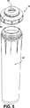
一実施態様を示すが、唯一の実施態様ではない本発明のフィルターアセンブリ20を示す図を参照する。フィルターアセンブリ20は、圧力容器22内にフィルターカートリッジ30を含む。本発明のフィルターアセンブリ20は、実質上アセンブリの外側表面として示されている圧力容器22を含み、この圧力容器は開口24を有し、この開口を介してフィルターカートリッジ30のネック44がフィルターヘッドを直接シールするように延伸する。本発明のフィルターアセンブリ20は、例えば圧力キャップ46の好適なバヨネットマウント32、ねじマウント又は他の接続手段等のいくつかの異なる方法によって、フィルタヘッドに固く固定されるように適合されている。好ましくは、本発明の圧力容器は、上記のような手段によって、フィルターヘッドに機械的に接続されるが、流体的にすなわち流体シールによってフィルターヘッドに接続されるのではない。本発明のフィルターアセンブリは、接続手段及び、フィルターカートリッジの流体入口及び出口通路を好ましくは含むネックの寸法、形状を適合させることによって、種々のフィルターヘッドに組み込むのに適合する。図に示されるフィルターアセンブリ20の好適な実施態様が、米国特許第4,857,189号及び意匠356,625号のシステムに説明されている形式のようなフィルターヘッドと共働する。本発明の開示を考察することによって、当業者は本発明のフィルターカートリッジと機能的に接続されるフィルターヘッドを組み立てることが可能である。米国特許第4,857,189号及び意匠356,625号に示されるようなシステムを組み立てる従来のカートリッジは、完全に圧力に耐える外壁を備える再利用できないフィルターとして従来技術に記載されている形式のものである。
【0010】
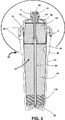
好適実施例において、フィルターヘッドを介してフィルターカートリッジ30の中央軸方向通路134内に、流体入口管状部材34の入口端部33を介して中央軸方向通路の底部の外へ、フィルター媒体36(1以上の媒体、空の空間、パッド、支持体等からなる)を介して上方へ、流体入口管状部材34の周囲の同心環状通路38を介してフィルターカートリッジ30の外へ流れる。好適実施例において、図3に特に引き立つように示されるように、3つの異なる媒体136、137、138が直列に配されているが、他の構成を利用することもできる。フィルターカートリッジは、随意的に、いくらかの液体が流体入口管状部材34を流れ落ち中央軸方向通路134を出て、液体の流れの一部が、媒体の3つの層を全て通過するのではなく、例えばフィルターの最上部の層138に直接流れ込む液体バイパスシステム35を含む。この液体バイパスシステム35は、下方の媒体を特定量の液体が迂回するような寸法の直径を有する1以上の孔を含む。あるいは他のシステムとすることができる。液体バイパスシステム35の設計は随意的であり、本発明の装置又は本発明の濾過方法の実施に不可欠のものではない。
【0011】
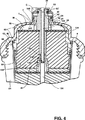
フィルターカートリッジ30は、圧力キャップ46の中央開口(開口24)を介して上方に延伸し、Oリング42'(図3及び8の溝42に示される)及び小径のOリング52'(図3及び8の溝52に示される)の2箇所でフィルターヘッド(図示しない)をシールする。このようにして、ネックは、フィルターカートリッジの同心環状入口及び出口システムを利用して、ヘッドにフィルターカートリッジを流体接続するのに必須の双方のシールを設け、保持する。これは、好適な実施態様が配列される場合に、フィルターカートリッジへの流体入口がシール位置52でシールされ、フィルターカートリッジの流体出口がOリング42'及び52'の間でシールされるということである。
【0012】
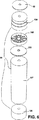
圧力容器22は、一般に開放端部と閉止端部を有する円筒形部材である圧力容器本体54と、その開放端部を横切って圧力容器本体に接続される圧力キャップ46とからなる。この接続は、図に示すように、ねじ接続とすることができるが、他の設計とすることもできる。圧力容器本体54は、本体を強化するための外側軸方向リブ56を有することが好ましい。圧力キャップ46は、圧力容器22の中央長手方向軸に沿って心合わせされ、フィルターカートリッジが圧力キャップの上方でシール位置42、52を有するヘッドに適切に結合可能であるような拡がりに突出するネック44を受容する上端開口24を有する。
【0013】
本発明の圧力容器22の内部空間の内側には本発明のフィルターカートリッジ30が配置される。このカートリッジ30は、カートリッジ本体64及びカートリッジキャップ66からなり、これらは好ましくはスナップ結合部68によって接続されるが、他の手段によって接続されても良い。カートリッジ本体64及びカートリッジキャップ66の接続は、好ましくはOリング8又は他の液体シール機構を含み、カートリッジ本体とカートリッジキャップの間から外部への液体の漏れを防ぐ。
【0014】
一般にカートリッジ本体64は、閉止された底部と開放された上部を有する円筒形であり、この開放された上部を横切って、カートリッジキャップ66が延伸する。カートリッジキャップ66は、半径方向外側に突出するタブ65を含み、このタブはカートリッジキャップ66の底部領域で周方向に隔置されている。タブ65は、カートリッジの内部要素及び媒体が組み込まれた後、カートリッジ本体の上部付近で周方向に隔置されているスロット67内にパチリと係合され、本体とキャップを接続する。カートリッジキャップの上端部は、キャップの最大径の約半分の直径を有し、外周溝42にOリングを保持する外側表面に適合する円筒形のネック44を含む。
【0015】
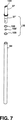
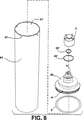
フィルターカートリッジの好ましい内部要素及び媒体は、1以上のフィルター又は処理媒体36、上部媒体フェルトパッド82、媒体セパレータ182、セパレータフェルトパッド282、中央管(「ステム」84)、ステム84に接続され入口端部33及びOリング42'、52'を有する流体入口管状部材34、バイパス管37、バイパス管37を流体入口管状部材34に対してシールするOリング108、ステム84に対してバイパス管37をシールするOリング108'及びOリング109が含まれるバイパスシステム35からなる。バイパスシステム35が遮断されている場合、管状部材34はステム84をシールするように適合される。中央ステム84は、カートリッジ本体64の底壁内部で放射状に形成されているリブ86に配置されている。リブ86は、ステム84の内部から媒体36内への流体の経路を創り出す。ステム84はリブ86から直立し、内部空間を介して延伸し、その内部空間に収容されているパッド、媒体セパレータ、媒体36を介して延伸し、入口端部33とシールする。媒体36は、液体/飲料水を処理、濾過又は調整することに依存して、単一の媒体とすることも組み合わせの媒体とすることもできる。媒体36は、好ましくは粒状活性炭及びイオン交換樹脂であり、この媒体の選択は、種々の媒体の上、間、下に支持体及びパッドを選択する際に、当業者によって考慮される。
【0016】
流体入口管状部材34の内側及び同軸に、ステム84に接続する下方部分37'を有し、随意的に穴部、Oリング、液体バイパスシステムをもたらすための他の構造を有するバイパススリーブ37が随意的に設けられる。図12及び13のスリーブ37の頂部に及びスリーブ37の頂部内側に示される構造133は、図3、4、8に示されるダストキャップCと共働する。ダストキャップCは、カートリッジの入口及び出口を清潔に保つために使用され、随意的に、構造133と共働して、スリーブを回転させることによって、スリーブ37の調節が液体バイパスを調節することを可能とする。上述したように、液体バイパスは随意的であり、締めること、閉鎖すること、排除することができる。
【0017】
流体の流れの観点から、流体は入口端部33に入り、(スリーブ37の内部を介して)、ステム84内に流れ落ち、カートリッジ64の底部の放射状リブ86を介して媒体136に流れ出る。上記で触れたように、液体バイパスシステム35は、随意的に組み込まれ、液体の一部分が媒体層の一部分のみを介して流れるようにする。媒体136から、一般に液体は他の媒体36、支持体及びパッドを介して軸方向上方に流れ、流体入口管の基部の開口部を介して、カートリッジキャップ66の内側表面と入口端部33の外側表面の間の環状空間38内に流れる。環状空間38は、環状空間38内で軸方向に連続し、カートリッジキャップに対して入口端部33を安定させるリブ71を含む。
【0018】
図3に最もよく示されているように、カートリッジ30は、圧力容器22の内側に密接して嵌め込まれ、圧力容器22は、カートリッジ30の実質上全てを取り囲む補強殻として機能する。しかしながら従来のフィルターカートリッジの多くのものとは異なり、本発明のカートリッジ30、特にネック44はその上端部で圧力容器の内側から延伸しフィルターヘッドを直接シールする。したがって圧力容器及びフィルターカートリッジは、互いに対する液体シールを必要としないが、本願の発明者は、フィルターカートリッジと圧力容器の間をシールすることを含む相応の実施態様を想定している。好適実施態様では、液体は圧力容器のキャップとカートリッジキャップの間を流れず、すなわちその間に達しない。つまり2つのキャップ46、66が接触又は開口24付近で互いに接近する箇所Lには一般的に液体シールは必要とされない。またカートリッジ本体64は、圧力容器の本体54の内側表面をシールする必要がないが、近接していなければならない。
【0019】
好ましくはカートリッジ30の種々の構成要素が再利用可能である。特にカートリッジ本体64、キャップ66、ステム84、スペーサ86は再利用可能なポリエチレン又はポリプロピレンであることが好ましい。種々の媒体36は、再利用可能な炭素、樹脂又は他の材料であることが好ましい。内側パッド及び媒体支持体は、ポリウレタン又はポリプロピレンのような再利用可能な材料から製造されることが好ましい。Oリングは再利用することができないが、この構成要素だけが再利用できず、これらのOリングは非常に小さく、容易に取り外すことができ、Oリング又はOリングの潤滑油に付着しているバクテリアや病原菌によって逆に汚染されることを防ぐために取り外されて廃棄されることが好ましい。
【0020】
ネック44の絶対的な壁の厚みは重要である。なぜなら一般に壁の厚みが、フィルターカートリッジ及びフィルターアセンブリの、それらが接続されるシステムの水圧に耐えるための安全要求に適合する臨界を与えるからである。例えば3.45Mpa(500psi)の試験に耐えるために、ポリプロピレン製のネックの壁の厚みTは3.18mm(0.125インチ)以上であることが好ましいが、フィルターカートリッジ本体の壁の厚みはわずかに約1.52mm(0.060インチ)(典型的には1.27mm(0.050インチ)から1.78mm(0.070インチ)の範囲)であればよい。したがって典型的には、本体の壁は、ネックの厚みのおおよそ半分以下の厚みである。種々の材料及び要求される圧力に対して他の厚みを適用することができる。ネックは、ネックの頂部144から、開口24を完全に横切り、圧力容器内に僅かな長さだけ下がり、ネックの底部244まで肉厚の壁で形成され、開口24付近のネックの破れが防止される。流体入口管状部材は、ネックの壁とは異なり、高い圧力に曝されることがないので、圧力容器から出るネックの壁と同心的に上方に延伸する流体入口管状部材34はネックの壁に匹敵する厚みとする必要はない。ネックの壁は、ネック内の水圧と外側大気の圧力との全差圧に耐えるが、一方流体入口管状部材はその内側(流入水)と外側(流出水)の双方が水に接し、2つの水の流れの差圧はフィルターカートリッジを介する圧力降下分にすぎない。
【0021】
したがって本発明において、高強度部分と低強度部分を有する外部壁を備えるような好適なフィルターカートリッジが開示される。好適な実施態様では、外部壁は本体及びキャップを含むフィルターカートリッジの全外壁である。高強度部分は3.28Mpa(475psi)よりも高い圧力に耐えるのに適合するように画定され、フィルターカートリッジの一方の端部から上方に延伸するネックであることが好ましい。低強度部分は、例えば69kPa(10psi)の僅かな圧力に耐えるのに適合するように画定され、上述のネックを除く、フィルターカートリッジの外壁の全てであることが好ましい。また本明細書及び特許請求の範囲における「耐圧」という用語は、それが使用されるプロセスにおいて、それ自体(大きく補強されることなく)が流体の圧力内に配置され、その圧力に耐えるということを意味する。「非耐圧」という用語は、構造の部分又は一部が大きな圧力に曝される場所に配置されないということを意味する。すなわち特に約69kPa(10psi)より小さい、取るに足らない圧力にしか曝されないということを意味する。
【0022】
この詳細な説明及び図面から理解されるように、フィルターカートリッジ及び圧力容器からなる本発明のフィルターアセンブリは、ヘッドから容易に取り外すことができ、再利用可能なフィルターカートリッジ30は、圧力容器本体から圧力容器キャップを回して、又は他の分離方法によって、圧力容器から容易に取り外すことができる。さらにカートリッジは、例えば以下に述べるように、分解された後に再利用される。フィルターカートリッジを容易に開放する他の機構を利用することができ、このような機構を本明細書では「ラッチ機構」と称し、この機構によって、カートリッジ本体に媒体を充填した後にフィルターカートリッジを閉じること、また使用後に、本体又はキャップに極端な力を加えることなく又はこれらを破壊することなく、フィルターカートリッジを開放することが可能となる。本明細書及び特許請求の範囲において、ラッチは、フィルタカートリッジ材料を切断又は切除せずに外部壁の部分がアンラッチされることを含まず、好ましくはラッチのタブ又は他の小さな部品の切断又は切除のみによって、本体に衝撃を与え、鋸で切断し、薄く切断するのではなく、実施されることを含む。フィルターカートリッジの外部壁の低強度部分の2つの部品が、例えば合わせ目又は接続部68で「ラッチ」され及び「アンラッチ」される部品である。好適なカートリッジが好適な圧力容器から取り外される場合、カートリッジは、プロセスの「フィルタアセンブリ側」の液体に接触する全ての表面及びシールとともに取り除かれる。したがって汚染されている可能性のある表面及びOリングは、再利用される圧力容器とともに残されるのではなく、定期的に取り外される。フィルターヘッドが再利用されず、すなわち交換されないので、いくらかの汚染物質がプロセスの「フィルターヘッド側」に存在することがあるが、Oリングがフィルターカートリッジとともに取り外されるとすれば、典型的には小さな領域である全ヘッド表面、例えばOリングの潤滑油の汚染の機会は最小となる。
【0023】
カートリッジ30を分解するために、好ましくは特別な適応構造が、カートリッジを押しつぶしたり、砕いたりすることなく、カートリッジ30の構成要素の分離を可能とすることを含む。この適応構造は、偶然の分離は考えられないが、再利用に先立つ目的のある分解は適切な工具によって容易に行われることが好ましい。好ましくは適応構造は、図12〜13に最もよく示されるスナップインタブ及びスロットシステムからなり、又は望ましくはカートリッジハウジングを押しつぶしたり、砕いたり、穴を開けることなく、カートリッジを開放する他の分離システムからなる。典型的にはタブ65は、カートリッジキャップ66の下方端部付近に一体的に形成される。カートリッジ本体64の上方端部付近の協働スロット67はスナップ嵌めによりタブ65を受容し、キャップ66を本体64に半恒久的に接続する。キャップ66の下方端部の外側周囲は、各タブ65の真上に切欠き部分69を含み、それによってタブ及びスロットの接続部に工具が到達する。再利用するユーザがフィルターカートリッジ30の分解を望む場合には、ユーザはキャップ66とタブの真上の本体64との間にナイフ又は鋭利な工具を差し込み、タブを下方へ切り取って、キャップから本体を外すのに十分なまでタブを取り除く。この形式又は他の分離形式は、ユーザすなわち道具がカートリッジの内側まで達し、カートリッジから内部要素及び媒体を取り外して外部キャップ及び本体の構成要素と同様、内部要素及び媒体の再利用を可能とする。
【0024】
本発明が特別な手段、材料、実施態様を参照して上記されたが、本発明は開示された事項に限定されず、むしろ添付の特許請求の範囲の記載と等価であるものまで拡張される。
【図面の簡単な説明】
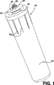
【図1】 本発明のフィルタアセンブリの一実施態様を上方から見た斜視図である。
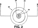
【図2】 図1のフィルターアセンブリの平面図である。
【図3】 図1及び2のフィルターアセンブリの、図2の3−3線に沿った断面図であり、ダストキャップを取り付けた状態である。
【図4】 図3の円で囲まれた部分の、フィルターアセンブリの上端を拡大して示す断面図である。
【図5】 図1〜4のフィルターアセンブリの圧力容器本体及び圧力キャップからなる圧力容器を分解して、側方から見た斜視図である。
【図6】 図1〜4の、フィルター材料、媒体支持体、フィルターパッドを分解して、側方から見た斜視図である。
【図7】 図1〜4のフィルターカートリッジの、中央ステム、任意の液体バイパススリーブ、Oリングを分解して、側方から見た斜視図である。
【図8】 図1〜4の実施態様の、カートリッジ本体、キャップ内の入口管状部材を含むカートリッジキャップ、シール部材、ダストキャップを分解して、側方から見た斜視図である。
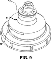
【図9】 本発明による、圧力容器のキャップに取り付けられているカートリッジキャップの実施態様を外側から見た拡大斜視図であり、ネックが圧力容器のキャップ内の開口を貫通してそこから上に突出している。
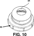
【図10】 図10の実施態様の圧力容器のキャップの斜視図である。
【図11】 図9のフィルターカートリッジのキャップの斜視図であり、圧力容器のキャップから分離して示す。
【図12】 図3及び8のカートリッジ本体及びカートリッジキャップを拡大して示す斜視図であり、本体とキャップをともにスナップ留めするための、タブ及びスロット接続システムの一実施態様を分解して図示する。
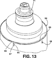
【図13】 図3、8及び12のフィルターカートリッジの上端の斜視図であり、カートリッジキャップがカートリッジ本体にスナップ留めされていることを示す。[0001]
BACKGROUND OF THE INVENTION
The present invention generally relates to a filter cartridge for water or drinking water such as used in water, ice water, carbonated water equipment or other drinking water vending machines. In particular, the present invention relates to a filter assembly that includes a filter cartridge substantially composed of reusable components and cooperates with a filter head / manifold. More particularly, the present invention allows all or substantially all surfaces in contact with the liquid to be periodically removed and reused, thereby reducing the chance of contamination due to prolonged use of the surface. It is related with the filter assembly which can be performed. The filter cartridge is substantially non-pressure resistant except for the neck of the filter cartridge, which extends to form a fluid seal with the head / manifold. Although the pressure vessel substantially surrounds the filter cartridge so as to hold and surround the wall of the filter cartridge under fluid pressure, the pressure vessel need not be fluid tight to the filter cartridge or the filter head / manifold.
[0002]
[Prior art]
Many filter systems for filtering water or other fluids consist of a filter that cooperates with a “filter head”. The term “filter head” as used herein includes fluid manifolds, valve heads or other connection devices that direct fluid to and from the filter. Typically, the filter seals the inner surface of the filter head so that liquid entering the filter head flows into the filter, exits the filter through the filter, and is discharged to the outlet port of the filter head. In the United States and Canada, water filters are typically required to accommodate and withstand pressures of about 3.45 MPa (500 psi) without breaking. In the United States, water systems are typically processed in the range of 275 to 861 kPa (40 to 125 psi), and typically NSF (International Hygiene Foundation) approved grades require maximum processing pressure for water filters That is, it typically needs to withstand a pressure of 3.45 MPa (500 psi) four times. In Canada, water filters need a safety factor that can withstand a pressure of about 3.50 MPa (508 psi) for 1 minute.
[0003]
In one common type of filter system, a disposable pressure vessel is connected directly to the filter head. In such a system, when the filter media in the pressure vessel is consumed, all pressure vessels must be discarded along with the media contained therein. Disposable pressure vessels are not easily reusable because there is no means to easily disassemble the pressure vessel. The outer wall of the disposable pressure vessel fully withstands pressure, i.e. safely withstands the liquid pressure of special systems with a large safety margin. Thus, disposable pressure vessels are more costly to replace because they use more plastic material or more expensive materials such as aluminum. Thus, the use of disposable pressure vessels is costly in terms of filter costs and environmental impact.
[0004]
In an alternative filter system, a disposable filter cartridge is supplied inside a pressure-resistant housing that connects to the filter head. In such systems, the pressure housing typically seals the head using an O-ring or other seal and a surface that contacts the liquid to be filtered. When the filter cartridge media is consumed, the filter cartridge is typically discarded and replaced with another cartridge. While conventional filter cartridges have several reusable components, some reusable components of the cartridge, such as granular activated carbon, contained within the cartridge are Could not be removed, and could not be easily accessed. While the filter cartridge is removed and disposed of, the thick pressure vessel is reused. During use, a portion of the pressure vessel functions in contact with the liquid to be filtered, thus the pressure vessel may become contaminated with bacteria or other non-hygienic substances. As the pressure vessel is continuously reused, the contaminated part remains used in the filter system, which may promote contamination problems in the filter system and in the liquid flowing through the filter system. is there.
[0005]
[Problems to be solved by the invention]
Accordingly, there is a need for an improved filter cartridge that is substantially reusable and thus can reduce the environmental and environmental impact caused by the filter cartridge. There is also a need for an economical and easy-to-use filter cartridge that is designed to be removed and reused at any time and the surfaces most likely to be contaminated are also replaced. The filter assembly of the present invention meets these requirements.
[0006]
[Means for Solving the Problems]
The present invention comprises a filter assembly that characterizes a substantially reusable filter cartridge. Virtually all of the components of the preferred cartridge are reusable. Its components include the cartridge body, cartridge cap, media, media support and retention pad, central stem / tube. The cartridge is not required, but includes an invented mechanism, i.e. a "latch" for disassembling the components of the filter cartridge, whereby the components are sectioned and sent to the appropriate recycling process.
[0007]
The filter assembly of the present invention includes, but is not essential, a pressure-resistant “pressure vessel” that substantially surrounds the filter cartridge, except for the protruding neck of the filter cartridge. This pressure vessel functions closely with the filter cartridge and safely supports and reinforces the non-pressure filter cartridge, but does not necessarily seal the cartridge. The neck of the filter cartridge is pressure resistant and protrudes from the pressure vessel and directly seals the filter head so that the entire outer surface of the filter cartridge is dry, i.e. without contact with liquid during filtration The total pressure towards the outside of the liquid against the atmosphere acts on the inner wall of the filter cartridge. This liquid pressure is contained in the neck of the filter cartridge which is not reinforced, while the liquid pressure is contained in the body of the filter cartridge in which the body wall of the filter cartridge is reinforced by the surrounding pressure vessel. This is achieved by the body of the filter cartridge consisting of a thin wall whose body wall is significantly thinner than the neck wall, which greatly reduces the amount of total plastic recycled after use, as well as excellent pressure resistance and NSF. Provides a safety factor.
[0008]
Accordingly, an object of the present invention includes the provision of a reusable filter cartridge for water and drinking water filtration. In the present invention, filtration includes filtration, treatment, or other processes. One objective is to provide a reusable filter cartridge as described above that significantly reduces the environmental impact of plastics or other materials used in the filter cartridge, which is easily disassembled. And separated into various components to make it suitable for reuse. A further object is to produce a reusable filter cartridge, while at the same time minimizing the total amount of plastic to be discussed in the reuse process. Minimizing the amount of plastic to be reused is preferably achieved by making the outer wall of the filter cartridge thin, except for the pressure-resistant neck, which is a relatively small part. Another object is a filter in which all or practically all of the liquid contacting surface is removed from the system after leaving the filter head and before being returned to the filter head when the filter cartridge is removed for reuse. It is to provide a cartridge system. The surface with which the liquid comes into contact is therefore not the surface of the pressure vessel, but rather the surface of the filter cartridge, which is changed whenever the filter cartridge is changed.
[0009]
DETAILED DESCRIPTION OF THE INVENTION
Reference is made to the figure showing a
[0010]
In the preferred embodiment, the filter media 36 (1) passes through the filter head into the central
[0011]
The
[0012]
The pressure vessel 22 is generally composed of a pressure vessel
[0013]
The
[0014]
Generally, the
[0015]
The preferred internal elements and media of the filter cartridge include one or more filters or
[0016]
Optionally, a
[0017]
From a fluid flow perspective, fluid enters the inlet end 33 (through the interior of the sleeve 37), flows down into the
[0018]
As best shown in FIG. 3, the
[0019]
Preferably, the various components of the
[0020]
The absolute wall thickness of the
[0021]
Accordingly, in the present invention, a suitable filter cartridge is disclosed that comprises an outer wall having a high strength portion and a low strength portion. In a preferred embodiment, the outer wall is the entire outer wall of the filter cartridge including the body and the cap. The high strength portion is preferably a neck that is defined to be compatible with withstanding pressures greater than 3.28 MPa (475 psi) and extends upward from one end of the filter cartridge. The low-strength portion is preferably all of the outer wall of the filter cartridge, except for the neck described above, which is defined to fit a slight pressure of, for example, 69 kPa (10 psi). Also, the term “pressure resistance” in the present description and claims means that, in the process in which it is used, itself (without significant reinforcement) is placed within the pressure of the fluid and withstands that pressure. Means. The term “non-pressure resistant” means that part or part of the structure is not located where it is exposed to high pressure. This means that it is only exposed to insignificant pressures, especially less than about 69 kPa (10 psi).
[0022]
As will be understood from this detailed description and drawings, the filter assembly of the present invention comprising a filter cartridge and a pressure vessel can be easily removed from the head and the
[0023]
To disassemble the
[0024]
Although the present invention has been described above with reference to specific means, materials, and embodiments, the present invention is not limited to that disclosed, but rather extends to equivalents of the appended claims. .
[Brief description of the drawings]
FIG. 1 is a top perspective view of one embodiment of a filter assembly of the present invention.
FIG. 2 is a plan view of the filter assembly of FIG.
3 is a cross-sectional view of the filter assembly of FIGS. 1 and 2 along line 3-3 of FIG. 2, with a dust cap attached.
4 is a cross-sectional view showing, in an enlarged manner, the upper end of the filter assembly in a portion surrounded by a circle in FIG. 3;
5 is an exploded perspective view of a pressure vessel including a pressure vessel body and a pressure cap of the filter assembly of FIGS.
6 is an exploded perspective view of the filter material, the medium support, and the filter pad of FIGS.
7 is an exploded perspective view of the filter cartridge of FIGS. 1 to 4 with the central stem, optional liquid bypass sleeve, and O-ring disassembled.
8 is an exploded perspective view of the cartridge body, the cartridge cap including the inlet tubular member in the cap, the seal member, and the dust cap of the embodiment of FIGS.
FIG. 9 is an enlarged perspective view from the outside of an embodiment of a cartridge cap attached to a pressure vessel cap according to the present invention, with the neck passing through an opening in the pressure vessel cap and up from there. It protrudes.
10 is a perspective view of the pressure vessel cap of the embodiment of FIG. 10;
FIG. 11 is a perspective view of the cap of the filter cartridge of FIG. 9, separated from the cap of the pressure vessel.
12 is an enlarged perspective view of the cartridge body and cartridge cap of FIGS. 3 and 8, with an exploded view of one embodiment of a tab and slot connection system for snapping the body and cap together. FIG. .
13 is a perspective view of the upper end of the filter cartridge of FIGS. 3, 8 and 12, showing the cartridge cap snapped to the cartridge body. FIG.
Claims (34)
フィルター媒体(36,136,137,138)を受容する内部容積を取り囲み及び画定するハウジング壁を有するカートリッジハウジング(64,66)であって、上端、下端(86)、長手方向軸、及びハウジング壁外径を有する、カートリッジハウジング(64,66)と、
前記長手方向軸とほぼ平行に前記上端から上方へ延びるネック(44)であって、ネック内部を取り囲み及び画定する外側ネック壁と、上端(144)と、前記ハウジング壁外径よりも小さなネック外径とを有し、前記外側ネック壁が、前記カートリッジハウジングの前記上端に接続される下端(244)を有する、ネック(44)とを備えており、
前記ハウジング壁が、破壊することなく、大気圧よりも68.0kPa(10psi)以下だけ高い内圧に耐えることができる厚みを有し、
前記外側ネック壁が、破壊することなく、大気圧よりも3.28MPa(475psi)より高い内圧に耐えることができる厚みを有し、
前記圧力容器(46,54)が、前記ネック(44)を除いて前記フィルターカートリッジ(30)全体を覆うように該フィルターカートリッジ(30)を受容する内部空洞を取り囲み及び画定する圧力容器壁を有し、該圧力容器壁が、前記カートリッジハウジングの前記上端を覆うように前記外側ネック壁の前記下端(244)へと延びており、
前記ネック(44)が、フィルターヘッド入口ポートから液体を受容するための液体入口通路(134)と、フィルターヘッド出口ポートへ液体を送るための液体出口通路(38)とを備え、前記入口通路(134)及び前記出口通路(38)の双方が、前記ネック内部内に存在し、及び該ネック(44)が更に、該ネックを前記フィルターヘッド入口ポートに対してシールするための入口シール(52')と、該ネック(44)を前記フィルターヘッド出口ポートに対してシールするための出口シール(42')とを備えており、
液体が、前記ネック(44)の内部の前記フィルターカートリッジ(30)に出入りし、前記カートリッジハウジング(64,66)の前記上端に接触せず、及び前記圧力容器(46,54)に接触しないようになっている、
フィルターヘッドに接続するための液体フィルターアセンブリ(20)。A liquid filter assembly (20) for connection to a filter head, the filter assembly (20) comprising a filter cartridge (30) and a pressure vessel (46, 54) , wherein the filter cartridge (30) ,
A cartridge housing (64,66) having a housing wall surrounding and defining an internal volume for receiving a filter medium (36,136,137,138) , the cartridge having an upper end, a lower end (86) , a longitudinal axis, and a housing wall outer diameter A housing (64, 66) ;
A neck (44) extending upwardly from the upper end substantially parallel to the longitudinal axis, the outer neck wall surrounding and defining the interior of the neck, the upper end (144), and an outer neck that is smaller than the outer diameter of the housing wall A neck (44) , wherein the outer neck wall has a lower end (244) connected to the upper end of the cartridge housing,
The housing wall has a thickness capable of withstanding an internal pressure higher than atmospheric pressure by 68.0 kPa (10 psi) or less without breaking,
The outer neck wall has a thickness capable of withstanding an internal pressure higher than 3.28 MPa (475 psi) above atmospheric pressure without breaking;
The pressure vessel (46, 54) has a pressure vessel wall surrounding and defining an internal cavity for receiving the filter cartridge (30) so as to cover the entire filter cartridge (30) except for the neck (44). The pressure vessel wall extends to the lower end (244) of the outer neck wall so as to cover the upper end of the cartridge housing;
The neck (44) comprises a liquid inlet passage (134) for receiving liquid from the filter head inlet port and a liquid outlet passage (38) for delivering liquid to the filter head outlet port, the inlet passage ( 134) and the outlet passageway (38) are both present within the neck interior, and the neck (44) further includes an inlet seal (52 ') for sealing the neck against the filter head inlet port. ) and comprises an outlet seal for sealing (42 ') with respect to said neck (44) the filter head outlet port,
The liquid enters and exits the filter cartridge (30) inside the neck (44) , does not contact the upper end of the cartridge housing (64, 66) , and does not contact the pressure vessel (46, 54). It has become,
Liquid filter assembly (20) for connection to the filter head.
前記ネック(44)が、破壊することなく、大気圧よりも3.28MPa(475psi)より高い内圧に耐えることができるものであり、
前記圧力容器(46,54)が、前記ネックの前記下端(244)へ向かって前記フィルターカートリッジ(30)の前記半径方向の壁を横切って半径方向に延びる半径方向部分を有しており、該圧力容器(46,54)が、前記ネック(44)を除いた前記カートリッジハウジング(64,66)全体を補強するようになっており、
前記カートリッジハウジング(64,66)の前記本体壁の厚みが、該カートリッジハウジング(64,66)の全プラスチック量が最小限となり再利用が改善されるように前記ネック(44)の厚みの半分未満である
ことを特徴とする、液体フィルターアセンブリ(20)。A liquid filter assembly (20) for connection to a filter head, wherein the assembly (20) is configured to be mechanically connected to the filter head; and A filter cartridge (30) removably received in the pressure vessel (46, 54), and the filter cartridge (30) is covered by a bottom wall (86) and the pressure vessel (46, 54). Broken and axial side walls, and includes a cartridge housing (64, 66) having a body wall made of the radial wall of the upper end, the cartridge housing (64, 66) further said radial wall almost neck to have a placed lower in the center has a (44), said neck (44), from said radial wall upstanding axially and liquid specific communication with the filter head Sealed against the filter head for Cormorant has a configured inlet and outlet passages (38,134), the filter assembly (20) is,
The neck (44) is capable of withstanding an internal pressure higher than 3.28 MPa (475 psi) above atmospheric pressure without breaking;
The pressure vessel (46, 54) has a radial portion extending radially across the radial wall of the filter cartridge (30) toward the lower end (244) of the neck; A pressure vessel (46, 54) reinforces the entire cartridge housing (64, 66) excluding the neck (44) ;
The thickness of the body wall of the cartridge housing (64, 66) is less than half of the thickness of the neck (44) so that the total plastic amount of the cartridge housing (64, 66) is minimized and reuse is improved. A liquid filter assembly (20), characterized in that:
前記ネック(44)が、破壊することなく、大気圧よりも3.28MPa(475psi)より高い内圧に耐えることが可能な厚みを有する外壁を有しており、前記上端の半径方向の壁を含め及び前記ネック(44)を除いた前記カートリッジハウジング(64,66)全体が、破壊することなく、68.9kPa(10psi)以下の圧力に耐えることができる肉厚を有しており、前記カートリッジハウジング(64,66)の前記唯一の耐圧部分が前記ネックであり、これにより前記ネック(44)を除いた前記カートリッジハウジング(64,66)全体が、該ネックの下端へと延びる半径方向部分を含む圧力容器の内部に受容され及び該圧力容器により補強され、及び前記カートリッジハウジング(64,66)の全プラスチック量が最小限となり再利用が改善される、再利用可能な液体フィルターカートリッジ(30)。A reusable liquid filter cartridge (30) removably inserted into a pressure vessel (46, 54) and connected to a filter head, the filter cartridge comprising a bottom wall, an axial side wall, and A cartridge housing (64, 66) having an upper end, the upper end having a radial wall and a neck (44) having a lower end disposed substantially in the center of the radial wall, A neck (44) has an inlet passage and an outlet passage configured to stand axially upright from the radial wall and to seal against the filter head to be in fluid communication with the filter head. And
The neck (44) has an outer wall having a thickness capable of withstanding an internal pressure greater than 3.28 MPa (475 psi) above atmospheric pressure without breaking, including the upper radial wall; The entire cartridge housing (64, 66) excluding the neck (44) has a thickness capable of withstanding a pressure of 68.9 kPa (10 psi) or less without breaking, and the cartridge housing (64 , 66) is the only pressure-resistant portion of the neck, so that the entire cartridge housing (64, 66) excluding the neck (44) includes a radial portion extending to the lower end of the neck. A reusable liquid filter cartridge (30) received within and reinforced by the pressure vessel, and wherein the total plastic amount of the cartridge housing (64, 66) is minimized and reuse is improved.
Applications Claiming Priority (3)
| Application Number | Priority Date | Filing Date | Title |
|---|---|---|---|
| US15901899P | 1999-10-12 | 1999-10-12 | |
| US60/159,018 | 1999-10-12 | ||
| PCT/US2000/028526 WO2001026772A2 (en) | 1999-10-12 | 2000-10-12 | Recyclable filter cartridge and pressure vessel |
Publications (2)
| Publication Number | Publication Date |
|---|---|
| JP2003511227A JP2003511227A (en) | 2003-03-25 |
| JP4570830B2 true JP4570830B2 (en) | 2010-10-27 |
Family
ID=22570727
Family Applications (1)
| Application Number | Title | Priority Date | Filing Date |
|---|---|---|---|
| JP2001529830A Expired - Fee Related JP4570830B2 (en) | 1999-10-12 | 2000-10-12 | Reusable filter cartridge and pressure vessel |
Country Status (11)
| Country | Link |
|---|---|
| US (2) | US6576129B1 (en) |
| EP (1) | EP1227868B1 (en) |
| JP (1) | JP4570830B2 (en) |
| AT (1) | ATE303859T1 (en) |
| AU (1) | AU1570401A (en) |
| DE (1) | DE60022534T2 (en) |
| DK (1) | DK1227868T3 (en) |
| ES (1) | ES2249305T3 (en) |
| PL (1) | PL197243B1 (en) |
| RU (1) | RU2248836C2 (en) |
| WO (1) | WO2001026772A2 (en) |
Families Citing this family (44)
| Publication number | Priority date | Publication date | Assignee | Title |
|---|---|---|---|---|
| US7166215B2 (en) * | 1999-10-12 | 2007-01-23 | Reid Roger P | Pressure vessel and recyclable filter cartridge |
| ATE357958T1 (en) * | 2001-07-13 | 2007-04-15 | Hemerus Medical Llc | CLASHABLE FILTER |
| US6923910B2 (en) * | 2003-01-07 | 2005-08-02 | Cuno Incorporated | Filter cartridge having bypass feature |
| US8215492B2 (en) | 2003-09-18 | 2012-07-10 | Pur Water Purification Products, Inc. | Water treatment devices and cartridges therefor |
| US7434697B2 (en) * | 2004-02-16 | 2008-10-14 | Fleetguard Inc. | Disposable, spin-on filter |
| US7614504B2 (en) * | 2004-02-16 | 2009-11-10 | Cummins Filtration Ip Inc. | Open-end flow entrance spin-on filter |
| US7138054B2 (en) * | 2004-05-05 | 2006-11-21 | Harmsco, Inc. | Cartridge filter system |
| US20060076226A1 (en) * | 2004-10-07 | 2006-04-13 | Michael Thomas Marcellus | Machine for desalinating salt water, brine water and impure water and the process for making same and a plant for making same |
| DE102004049876C5 (en) * | 2004-10-13 | 2010-04-29 | Brita Gmbh | filter cartridge |
| DE102004050269A1 (en) * | 2004-10-14 | 2006-04-20 | Institut Für Solarenergieforschung Gmbh | Process for the contact separation of electrically conductive layers on back-contacted solar cells and solar cell |
| DK2201995T3 (en) * | 2005-01-27 | 2018-10-01 | Ecowater Systems Llc | Method for regulating a reverse osmosis water treatment system |
| US20070199879A1 (en) * | 2006-01-10 | 2007-08-30 | Bors Mark S | Water filter assembly |
| KR100718566B1 (en) * | 2006-06-23 | 2007-05-15 | 주식회사 마이크로필터 | Water purification filter assembly |
| KR100721327B1 (en) * | 2006-06-23 | 2007-05-25 | 주식회사 마이크로필터 | Water purification filter assembly |
| DE202006011991U1 (en) | 2006-08-03 | 2007-12-06 | Mann + Hummel Gmbh | Air filter unit with a radially split housing |
| WO2008017495A2 (en) * | 2006-08-10 | 2008-02-14 | Aquis Wasser-Luft-Systeme Gmbh, Lindau Zweigniederlassung Rebstein | Tank |
| US8398852B2 (en) * | 2006-10-12 | 2013-03-19 | Bruce D. Burrows | Drainless reverse osmosis water purification system |
| DE102006050302B4 (en) * | 2006-10-23 | 2017-05-24 | Aquis Wasser-Luft-Systeme Gmbh, Lindau, Zweigniederlassung Rebstein | Tank, filter cartridge and device with tank |
| ITUD20070024A1 (en) * | 2007-02-07 | 2008-08-08 | Ohg Ind O M I Srl | FILTER UNIT FOR A HEAT EXCHANGER |
| DE102007006772A1 (en) * | 2007-02-12 | 2008-08-14 | Robert Bosch Gmbh | Filter and filter arrangement |
| US9211488B2 (en) * | 2007-07-13 | 2015-12-15 | Cummins Filtration Ip, Inc. | Fluid filter with localized flow attachment |
| US9308476B2 (en) * | 2007-07-13 | 2016-04-12 | Cummins Filtration Ip, Inc. | Filter with localized flow attachment and filter head |
| US7540957B1 (en) * | 2008-03-21 | 2009-06-02 | Pentair Filtration, Inc. | Modular drinking water filtration system with bottom load cartridges with grip-enhanced end rings and color coding |
| US20090321340A1 (en) * | 2008-06-25 | 2009-12-31 | Envirogard Products Limited | Filter cartridge for use with a filter head assembly |
| GB0812457D0 (en) * | 2008-07-08 | 2008-08-13 | Parker Hannifin U K Ltd | A Filter |
| PT2168469E (en) * | 2008-09-25 | 2013-08-22 | Nestec Sa | Filter cartridge for a beverage machine and beverage machine with a filter cartridge |
| DE102010022954A1 (en) * | 2009-06-25 | 2010-12-30 | Aquis Wasser-Luft-Systeme Gmbh, Lindau, Zweigniederlassung Rebstein | Water filter with hardener reducer and residual hardness stabilizer |
| GB2477942B (en) * | 2010-02-18 | 2012-07-04 | Icon Technology Systems Ltd | Water filters |
| JP2011206722A (en) * | 2010-03-30 | 2011-10-20 | Kurita Water Ind Ltd | Ion exchange apparatus and subsystem for ultrapure water generator |
| DE102010035465A1 (en) * | 2010-08-21 | 2012-02-23 | Mann + Hummel Gmbh | Filter for filtration of fluids, filter bowl and filter head |
| JP5801063B2 (en) * | 2011-03-02 | 2015-10-28 | 日立オートモティブシステムズ株式会社 | Brake device |
| US9447759B2 (en) | 2012-06-12 | 2016-09-20 | Cummins Filtration Ip, Inc. | Filter element endplate defining inflow and outflow flow paths |
| CN104812461B (en) | 2012-06-29 | 2016-12-07 | 3M创新有限公司 | There is the medium cylinder of adjustable bypass |
| US10183874B2 (en) | 2013-12-18 | 2019-01-22 | Ds Services Of America, Inc. | Water purification system with active vibration |
| JP6677097B2 (en) | 2016-06-22 | 2020-04-08 | トヨタ紡織株式会社 | Ion exchanger |
| CN110769913B (en) | 2017-05-31 | 2021-11-16 | 帕克-汉尼芬公司 | Filter element with twist lock and/or sliding piston, assembly and method |
| EP3731948A1 (en) * | 2017-12-29 | 2020-11-04 | W.F. S.R.L. | Filter for beverage dispensing machines |
| KR102591791B1 (en) * | 2018-06-27 | 2023-10-23 | 케이엑스 테크놀러지스, 엘엘씨 | Filter connection using correlated magnetic torque structure |
| US11725781B2 (en) | 2019-02-11 | 2023-08-15 | Watts Regulator Co. | Pressure relief cover assembly |
| US11333264B2 (en) | 2019-02-11 | 2022-05-17 | Watts Regulator Co. | Manifold assembly for a water filter system |
| US11471794B2 (en) * | 2019-02-11 | 2022-10-18 | Watts Regulator Co. | Filter cartridge for a whole house water filtering system |
| USD961043S1 (en) * | 2019-09-04 | 2022-08-16 | Tianjin Yunda Industry And Trade Co., Ltd. | Water filter cartridge |
| IT201900017192A1 (en) * | 2019-09-25 | 2021-03-25 | Fil Tech Srl | CLOSURE SYSTEM FOR A RECIPE OF A FILTRATION APPARATUS |
| WO2024006193A1 (en) * | 2022-06-27 | 2024-01-04 | Cummins Filtration Inc. | Split resin bed, low pressure drop, and replaceable cartridge deionization filter |
Family Cites Families (42)
| Publication number | Priority date | Publication date | Assignee | Title |
|---|---|---|---|---|
| US3684100A (en) | 1971-04-05 | 1972-08-15 | Sam Close | Filter assembly and disposable filter element therefor |
| US3935106A (en) | 1974-01-23 | 1976-01-27 | Lipner Herbert D | Water filter assembly |
| US4082673A (en) | 1974-06-10 | 1978-04-04 | Amf Incorporated | Filter asembly with integral service shut-off valve |
| IT1052943B (en) | 1975-02-07 | 1981-08-31 | Daimler Benz Ag | IMPROVEMENT IN LIQUID FILTERS, IN PARTICULAR FUEL |
| US4052307A (en) | 1976-07-08 | 1977-10-04 | Wix Corporation | Universal filter mounting attachment |
| US4133763A (en) | 1977-12-05 | 1979-01-09 | Pall Corporation | Filter assembly with replaceable filter element |
| US4396512A (en) | 1979-06-01 | 1983-08-02 | Everpure, Inc. | Bacteriostatic filter media |
| DE3126507A1 (en) | 1981-07-04 | 1983-01-20 | Surculus AG, Vaduz | "ARMATURE" |
| US4349438A (en) | 1981-07-08 | 1982-09-14 | Sims Oil, Inc. | Oil refiner |
| JPS6029287B2 (en) | 1981-07-29 | 1985-07-10 | 栄市 杉浦 | liquid filter machine |
| US4402828A (en) | 1982-06-14 | 1983-09-06 | Edens Jeffrey I | Pressure filter vessel |
| US4559138A (en) | 1983-10-03 | 1985-12-17 | Harmsco, Inc. | End connected filter cartridges |
| US4504387A (en) | 1983-10-31 | 1985-03-12 | Lemire George J | System and method for water purification |
| JPS60179189A (en) | 1984-02-27 | 1985-09-13 | Hitachi Ltd | Water purifier |
| US4645601A (en) | 1984-08-31 | 1987-02-24 | Everpure, Inc. | Quick change reverse osmosis assembly |
| US4764275A (en) | 1985-10-25 | 1988-08-16 | Robichaud Arthur W | Fluid filter and method for attaching same in sealing relation to a filter mount |
| US4654142A (en) | 1985-11-18 | 1987-03-31 | Everpure, Inc. | Filtering system |
| US4725354A (en) | 1986-03-07 | 1988-02-16 | Everpure, Inc. | Filtering system |
| USRE34050E (en) | 1986-03-07 | 1992-09-01 | Everpure, Inc. | Filtering system |
| US4719012A (en) | 1986-05-30 | 1988-01-12 | Caterpillar Inc. | Twist on disposable filter |
| US4806240A (en) | 1987-06-12 | 1989-02-21 | Cuno, Incorporated | Adapter and cartridge assembly |
| US4904382A (en) | 1987-11-23 | 1990-02-27 | Everpure, Inc. | Filter cartridge security for locking between operating and non-operating positions |
| US4781830A (en) | 1988-04-19 | 1988-11-01 | Osmonics, Inc. | Cross flow filtration apparatus and closure assembly therefor |
| US4857189A (en) | 1988-10-13 | 1989-08-15 | Everpure, Inc. | Filter cartridge with a lugged concentric closure portion |
| US4956086A (en) | 1988-10-13 | 1990-09-11 | Everpure, Inc. | Filter cartridge with a lugged concentric closure portion |
| US5080787A (en) * | 1989-11-02 | 1992-01-14 | Fleetguard, Inc. | High-pressure filter assembly, method and apparatus for forming high-pressure filters |
| US5024761A (en) | 1990-01-25 | 1991-06-18 | Deibel Richard J | High-strength quick-disconnect tube filter |
| US5013434A (en) | 1990-04-10 | 1991-05-07 | Gilbarco, Inc. | Fluid filter cartridge support housing |
| US5026478A (en) | 1990-05-03 | 1991-06-25 | Nippon Roki Co., Ltd. | Metal holder and protector for a disposable plastic capsule |
| US5104537A (en) | 1990-07-20 | 1992-04-14 | Donaldson Company, Inc. | High pressure hydraulic spin-on filter |
| JPH04225806A (en) * | 1990-12-27 | 1992-08-14 | Kanebo Ltd | Dual construction filter container |
| GB9101772D0 (en) | 1991-01-28 | 1991-03-13 | Philips Electronic Associated | A water cleaning device |
| US5171430A (en) | 1991-05-17 | 1992-12-15 | Fleetguard, Inc. | Plastic filter |
| GB2258166B8 (en) * | 1991-08-02 | 1995-07-17 | Ac Delco Systems Overseas Corp | Disposable oil filter |
| US5399263A (en) | 1992-09-24 | 1995-03-21 | Barnstead Thermolyne | Water purifier |
| US5376272A (en) | 1993-11-08 | 1994-12-27 | Porous Media Corporation | Filter assembly including a filter and closure member |
| US5643448A (en) | 1994-09-26 | 1997-07-01 | Glacier Metal Company Limited | Spin-on filter assembly incorporating a re-usable tubular filter screen |
| US5685985A (en) | 1995-12-20 | 1997-11-11 | Baldwin Filters, Inc. | Environmentally friendly filter cartridge |
| US5656159A (en) | 1996-04-12 | 1997-08-12 | Sta-Rite Industries, Inc. | Filter cartridge with integral bactericide |
| US5653871A (en) | 1996-04-24 | 1997-08-05 | Everpure, Inc. | Filter assembly with O-ring protection |
| US5762789A (en) | 1996-06-28 | 1998-06-09 | Millipore Corporation | Disposable membrane module with low-dead volume |
| US5919362A (en) * | 1997-04-28 | 1999-07-06 | Cuno, Inc. | Expandable encapsulated filter cartridge assembly |
-
2000
- 2000-10-12 RU RU2002112320/15A patent/RU2248836C2/en not_active IP Right Cessation
- 2000-10-12 DE DE60022534T patent/DE60022534T2/en not_active Expired - Lifetime
- 2000-10-12 US US10/110,605 patent/US6576129B1/en not_active Expired - Lifetime
- 2000-10-12 AU AU15704/01A patent/AU1570401A/en not_active Abandoned
- 2000-10-12 JP JP2001529830A patent/JP4570830B2/en not_active Expired - Fee Related
- 2000-10-12 DK DK00978223T patent/DK1227868T3/en active
- 2000-10-12 AT AT00978223T patent/ATE303859T1/en active
- 2000-10-12 PL PL356189A patent/PL197243B1/en not_active IP Right Cessation
- 2000-10-12 WO PCT/US2000/028526 patent/WO2001026772A2/en active IP Right Grant
- 2000-10-12 US US09/688,509 patent/US6533931B1/en not_active Expired - Lifetime
- 2000-10-12 EP EP00978223A patent/EP1227868B1/en not_active Expired - Lifetime
- 2000-10-12 ES ES00978223T patent/ES2249305T3/en not_active Expired - Lifetime
Also Published As
| Publication number | Publication date |
|---|---|
| WO2001026772A3 (en) | 2001-11-01 |
| WO2001026772A2 (en) | 2001-04-19 |
| DE60022534D1 (en) | 2005-10-13 |
| PL197243B1 (en) | 2008-03-31 |
| PL356189A1 (en) | 2004-06-14 |
| WO2001026772B1 (en) | 2002-01-03 |
| RU2002112320A (en) | 2004-01-27 |
| EP1227868B1 (en) | 2005-09-07 |
| AU1570401A (en) | 2001-04-23 |
| JP2003511227A (en) | 2003-03-25 |
| DK1227868T3 (en) | 2005-12-27 |
| EP1227868A2 (en) | 2002-08-07 |
| ES2249305T3 (en) | 2006-04-01 |
| US6533931B1 (en) | 2003-03-18 |
| RU2248836C2 (en) | 2005-03-27 |
| US6576129B1 (en) | 2003-06-10 |
| ATE303859T1 (en) | 2005-09-15 |
| DE60022534T2 (en) | 2006-06-22 |
Similar Documents
| Publication | Publication Date | Title |
|---|---|---|
| JP4570830B2 (en) | Reusable filter cartridge and pressure vessel | |
| US7638045B2 (en) | Pressure vessel and recyclable filter cartridge | |
| US6193886B1 (en) | Sub-micron sport bottle with ceramic filtering element | |
| US4948505A (en) | Quick-change filter cartridge and head therefor | |
| US4877521A (en) | Quick-change filter cartridge and head therefor | |
| US6511598B2 (en) | Concentrically arranged filter element assembly | |
| US5122272A (en) | Drinking water supply container having a removably mounted filter device | |
| US5891334A (en) | Filter cartridge retaining assembly | |
| KR101608551B1 (en) | Modular drinking water filtration system with removeable and replaceable spindle | |
| US5167819A (en) | Canteen having a removably mounted filter device | |
| US4735716A (en) | Quick-change filter cartridge and head therefor | |
| US5151180A (en) | Radial and axial flow stage filter device | |
| US4711717A (en) | Filter cartridge for fluids | |
| JPH0852465A (en) | Filtration device of water purifier | |
| US5256287A (en) | Cartridge filter for faucet attachment | |
| JPH06509023A (en) | vacuum filter assembly | |
| US20020117442A1 (en) | Manually pressurized water filtering container | |
| JPH10211954A (en) | Water treatment cartridge, structure of combining cartridge with drink bottle, and water treatment method employing the cartridge | |
| JPH11253936A (en) | Water purifier | |
| AU2002244260B2 (en) | Filter element assembly | |
| JP2001334260A (en) | Water purifier | |
| JPH03157105A (en) | Gas transmissible membrane for liquid degasifier and its production | |
| AU2002244260A1 (en) | Filter element assembly | |
| CA2500450A1 (en) | Water filter bottle |
Legal Events
| Date | Code | Title | Description |
|---|---|---|---|
| A521 | Request for written amendment filed |
Free format text: JAPANESE INTERMEDIATE CODE: A523 Effective date: 20050216 |
|
| A621 | Written request for application examination |
Free format text: JAPANESE INTERMEDIATE CODE: A621 Effective date: 20050216 |
|
| A977 | Report on retrieval |
Free format text: JAPANESE INTERMEDIATE CODE: A971007 Effective date: 20070402 |
|
| A131 | Notification of reasons for refusal |
Free format text: JAPANESE INTERMEDIATE CODE: A131 Effective date: 20080617 |
|
| A601 | Written request for extension of time |
Free format text: JAPANESE INTERMEDIATE CODE: A601 Effective date: 20080917 |
|
| A602 | Written permission of extension of time |
Free format text: JAPANESE INTERMEDIATE CODE: A602 Effective date: 20080925 |
|
| A521 | Request for written amendment filed |
Free format text: JAPANESE INTERMEDIATE CODE: A523 Effective date: 20081217 |
|
| A131 | Notification of reasons for refusal |
Free format text: JAPANESE INTERMEDIATE CODE: A131 Effective date: 20090630 |
|
| A601 | Written request for extension of time |
Free format text: JAPANESE INTERMEDIATE CODE: A601 Effective date: 20090930 |
|
| A602 | Written permission of extension of time |
Free format text: JAPANESE INTERMEDIATE CODE: A602 Effective date: 20091007 |
|
| A521 | Request for written amendment filed |
Free format text: JAPANESE INTERMEDIATE CODE: A523 Effective date: 20100104 |
|
| TRDD | Decision of grant or rejection written | ||
| A01 | Written decision to grant a patent or to grant a registration (utility model) |
Free format text: JAPANESE INTERMEDIATE CODE: A01 Effective date: 20100803 |
|
| A01 | Written decision to grant a patent or to grant a registration (utility model) |
Free format text: JAPANESE INTERMEDIATE CODE: A01 |
|
| A61 | First payment of annual fees (during grant procedure) |
Free format text: JAPANESE INTERMEDIATE CODE: A61 Effective date: 20100811 |
|
| FPAY | Renewal fee payment (event date is renewal date of database) |
Free format text: PAYMENT UNTIL: 20130820 Year of fee payment: 3 |
|
| R150 | Certificate of patent or registration of utility model |
Free format text: JAPANESE INTERMEDIATE CODE: R150 |
|
| LAPS | Cancellation because of no payment of annual fees |