JP4570552B2 - Loop antenna and communication equipment - Google Patents
Loop antenna and communication equipment Download PDFInfo
- Publication number
- JP4570552B2 JP4570552B2 JP2005333741A JP2005333741A JP4570552B2 JP 4570552 B2 JP4570552 B2 JP 4570552B2 JP 2005333741 A JP2005333741 A JP 2005333741A JP 2005333741 A JP2005333741 A JP 2005333741A JP 4570552 B2 JP4570552 B2 JP 4570552B2
- Authority
- JP
- Japan
- Prior art keywords
- antenna
- loop antenna
- polarization
- opening
- cuts
- Prior art date
- Legal status (The legal status is an assumption and is not a legal conclusion. Google has not performed a legal analysis and makes no representation as to the accuracy of the status listed.)
- Expired - Fee Related
Links
Images


Description
本発明は、例えば携帯電話や無線LAN、テレビ(テレビジョン受像機)等の無線通信機器、その他の各種通信機器等に使用されるループアンテナ、および通信機器に関するものであり、特に、広帯域の送受信に有効な板状のループアンテナ、および通信機器に関する。 The present invention relates to a loop antenna and a communication device used in a wireless communication device such as a mobile phone, a wireless LAN, a television (television receiver), and other various communication devices, and in particular, a broadband transmission / reception. The present invention relates to a plate-like loop antenna that is effective for communication, and communication equipment.
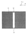
送受信用のループアンテナ、特に、携帯電話や無線LAN等の無線通信機器、その他の各種通信機器等において使用される広帯域のループアンテナとして、図8に平面図で示す板状のループアンテナが知られている。図8に示す広帯域のループアンテナは、図11に示す従来のいわゆる1波長線状導体のループアンテナを広帯域化させたものである。図11において、11は中央部に長方形状の開口12を有する線状の導体を枠状に成形してなるアンテナ導体、21はアンテナ導体11の一端部に形成された給電回路である。
A plate-like loop antenna shown in a plan view in FIG. 8 is known as a loop antenna for transmission / reception, in particular, as a broadband loop antenna used in wireless communication devices such as mobile phones and wireless LANs, and other various communication devices. ing. The broadband loop antenna shown in FIG. 8 is obtained by extending the bandwidth of the conventional so-called single-wavelength linear conductor loop antenna shown in FIG. In FIG. 11, 11 is an antenna conductor formed by forming a linear conductor having a
図11に示す従来のループアンテナにおいては、アンテナ導体11の1周の長さが約1波長に当たる周波数で共振する。
In the conventional loop antenna shown in FIG. 11, the length of one round of the
図12は、図11に示す従来のループアンテナの共振時の電流分布を示す模式図である。図12において、41は電流分布を示す曲線、42は電流の向きであり、アンテナ導体11の各部位について、曲線41とアンテナ導体11との間の距離が長いほど、その部位における電流が強いことを示している。
FIG. 12 is a schematic diagram showing a current distribution during resonance of the conventional loop antenna shown in FIG. In FIG. 12, 41 is a curve indicating the current distribution, 42 is the direction of current, and for each part of the
電流分布41はX方向の2辺の中央で最大(腹)、Y方向の2辺の中央で最小(節)となる。このとき、電流の向きはX方向の2辺においては、対向する辺々で同じ向きとなり、互いに強め合う。一方、Y方向の2辺においては、対向する辺々で逆向きとなり、互いに打ち消し合う。以上より、X方向に強い電流分布となり、偏波がX方向の電波を送受信することができる。また、上記のような電流分布であることから、指向性はYZ面内において無指向性、X軸方向にヌル点を持つ。
The
一方、図8において、11は中央部に帯状の開口12を有する平面状のアンテナ導体、21は開口12の長手方向(Y方向)の延長上に位置するようにしてアンテナ導体の一端部に形成された給電回路である。
On the other hand, in FIG. 8, 11 is a planar antenna conductor having a strip-
図8に示す従来の広帯域のループアンテナは、1周の長さの異なる1波長ループアンテナが、複数、一つの平面状のアンテナ導体に包含されたものとみなすことができる。図8に記載の広帯域のループアンテナにおいては、仮想の線状のアンテナ導体(図示せず)の1周の長さが、開口12の周囲に当たる比較的短いものから、アンテナ導体11の外縁部に当たる比較的長いものまでと範囲を持ったものとなり、その長さに対応する周波数も範囲を持ったものとなって広帯域特性を有する。なお、電流分布は図11に示す従来のループアンテナと同様である。つまり、偏波がX方向の電波を送受信することができ、指向性はYZ面内において無指向性である。
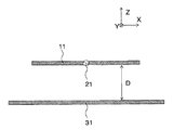
しかしながら、従来のループアンテナ、例えば、図8に示すようなループアンテナ(広帯域の送受信が可能な板状のループアンテナ等)は、YZ面内で無指向性で、指向性があまり強くないので、単独で特定の一方向に対して高い送受信の強度、すなわち利得を得ることが難しい。そのため、例えばテレビ放送の据え置き型受信アンテナのような、ある方向に高い受信感度、すなわち指向性が強く、高利得が求められる用途においては、図13に断面図で示すような、アンテナ導体11に平行に電波の周波数の約1/4波長程度にあたる距離Dの間隔をおいて、寸法がアンテナ導体11以上の反射板31を設ける必要があり、小型化が難しいという問題点があった。また、このループアンテナを搭載する通信機器が大きくなるという問題点があった。
However, a conventional loop antenna, for example, a loop antenna as shown in FIG. 8 (such as a plate-like loop antenna capable of transmitting and receiving a wide band) is omnidirectional in the YZ plane and directivity is not so strong. It is difficult to obtain high transmission / reception strength, that is, gain, in a specific direction alone. For this reason, in applications that require high reception sensitivity in a certain direction, that is, high directivity and high gain, such as a stationary receiving antenna for television broadcasting, the
また、図8に示す従来のループアンテナは偏波が1方向(図8のX方向)にしか対応しておらず、例えば携帯電話のような移動体機器に搭載する用途においては、ループアンテナの向きが一定しないため、ループアンテナで送受信される電波は、その偏波の方向がXY面に対して相対的に移動する。そのため、アンテナが高い効率で送受信可能な偏波の方向と、電波(アンテナが受信しようとする電波やアンテナが送信すべき電波)の偏波の方向が一致しない場合が生じ、電波の送受信の効率が低下するという問題点があった。 In addition, the conventional loop antenna shown in FIG. 8 corresponds to only one direction of polarization (the X direction in FIG. 8). For example, the loop antenna is used in a mobile device such as a mobile phone. Since the direction is not constant, the direction of polarization of radio waves transmitted and received by the loop antenna moves relative to the XY plane. For this reason, the direction of polarization that the antenna can transmit and receive with high efficiency may not match the direction of polarization of the radio wave (the radio wave that the antenna is trying to receive and the radio wave that the antenna is to transmit). There has been a problem of lowering.
そのため、従来の通信機器は、搭載されるアンテナについて、小型で、高利得(特に、特定の一方向に対する高利得)、高効率での送受信が可能なものとすることが難しいことにより、小型化や高利得化が妨げられているという問題があった。この問題は、特に、上述したようにテレビ放送の受信用アンテナ等において顕著であり、テレビを、明瞭な映像,音声を提供可能としながら、小型化したり携行可能としたりする上で大きな障害となっている。 Therefore, conventional communication devices are small in size because it is difficult to make the mounted antennas small, high gain (especially high gain in a specific direction), and capable of transmitting and receiving with high efficiency. In addition, there is a problem that high gain is hindered. This problem is particularly noticeable in TV broadcast receiving antennas as described above, and is a major obstacle to miniaturization and portability of televisions while providing clear video and audio. ing.
本発明は、上記問題点に鑑みて完成されたものであり、その目的は、小型で、利得が高く、またあらゆる偏波(特にXY面内)に対応した、すなわち偏波共用のループアンテナおよび通信機器を提供することにある。 The present invention has been completed in view of the above problems, and its object is to achieve a compact, high gain, and compatible with all polarized waves (especially in the XY plane). It is to provide communication equipment.
本発明のループアンテナは、中央部に帯状の開口を有する平面四角形状のアンテナ導体と、該アンテナ導体の一端部に、前記開口の長手方向の延長線上に位置するようにして形成された給電回路とを備えるループアンテナであって、前記アンテナ導体は、外縁部に複数の切込みが設けられており、該複数の切込みが前記アンテナ導体の向かい合う辺の間で互いに向かい合う位置に形成されていることを特徴とする。
The loop antenna of the present invention includes a planar rectangular antenna conductor having a strip-shaped opening at the center, and a feeder circuit formed at one end of the antenna conductor so as to be positioned on the longitudinal extension of the opening. a loop antenna comprising bets, the antenna conductor, a plurality of notches are provided in the outer edge portion, being formed on one another facing position between the sides facing cuts said plurality of the said antenna conductor Features.
本発明のループアンテナは、上記構成において前記複数の切込みのうち少なくとも1つが前記開口の長手方向に平行であることを特徴とする。
The loop antenna of the present invention is characterized in that, in the above configuration, at least one of the plurality of cuts is parallel to a longitudinal direction of the opening.
本発明のループアンテナは、上記構成において前記複数の切込みのすべてが前記開口の長手方向に平行であることを特徴とする。
Loop antenna of the present invention is characterized in that all the notches before Kifuku number in the above-described structure are parallel to the longitudinal direction of the opening.
本発明のループアンテナは、上記構成において前記複数の切込みのうち少なくとも1つが前記開口の長手方向に垂直であることを特徴とする。
The loop antenna of the present invention is characterized in that, in the above configuration, at least one of the plurality of cuts is perpendicular to the longitudinal direction of the opening.
本発明のループアンテナは、上記構成において前記複数の切込みのすべてが前記開口の長手方向に垂直であることを特徴とする。
Loop antenna of the present invention is characterized in that all the notches before Kifuku number in the above-described structure is perpendicular to the longitudinal direction of the opening.
本発明の通信機器は、上記本発明のループアンテナが搭載されて成ることを特徴とする。 A communication device of the present invention is characterized in that the loop antenna of the present invention is mounted.
本発明のループアンテナによれば、中央部に帯状の開口を有する平面四角形状のアンテナ導体と、アンテナ導体の一端部に、開口の長手方向の延長線上に位置するようにして形成された給電回路とを備えるループアンテナであって、アンテナ導体は、外縁部に複数の切込みが設けられており、複数の切込みがアンテナ導体の向かい合う辺の間で互いに向かい合う位置に形成されていることから、平面状のアンテナ導体は、全体として一つの広帯域ループアンテナとして働く。また同時に、このループアンテナは、各切込みが、その長さ(アンテナ導体の外縁から内側に入り込んだ長さ)が約1/4波長となる周波数において、切込みの長さ方向に対して直交する方向の偏波に対応するノッチアンテナに近い働き
をする。つまり、各切込みがループアンテナ本体とは別に個々にアンテナとして機能し、電波を送受信することができる。
According to the loop antenna of the present invention, a planar rectangular antenna conductor having a band-shaped opening at the center, and a feeder circuit formed at one end of the antenna conductor so as to be positioned on an extension line in the longitudinal direction of the opening Since the antenna conductor is provided with a plurality of cuts in the outer edge portion, and the plurality of cuts are formed at positions facing each other between the opposite sides of the antenna conductor , the planar shape The antenna conductor of this works as one broadband loop antenna as a whole. At the same time, this loop antenna has a direction in which each notch is orthogonal to the length direction of the notch at a frequency at which the length (the length entering from the outer edge of the antenna conductor) is about ¼ wavelength. It works close to a notch antenna corresponding to the polarized wave. That is, each incision functions individually as an antenna separately from the loop antenna body, and can transmit and receive radio waves.
このとき、切込みで形成されたアンテナによる利得によって高利得化、偏波共用化が可能である。 At this time, it is possible to increase the gain and share the polarization by the gain of the antenna formed by the cut.
そのため、例えば寸法がアンテナ導体以上の反射板を設けることなく高利得化することができるとともに、アンテナが送受信可能な偏波の方向と、実際に送受信しようとする電波の偏波の方向とを高い確度で一致させることができる。 Therefore, for example, the gain can be increased without providing a reflector having a size larger than that of the antenna conductor, and the polarization direction in which the antenna can transmit and receive and the polarization direction of the radio wave to be actually transmitted and received are high. Can be matched with accuracy.
したがって、小型で、利得が高く、またあらゆる偏波に対応した、すなわち偏波共用のループアンテナを提供することができる。 Therefore, it is possible to provide a loop antenna that is small in size, has a high gain, and supports all types of polarization, that is, a polarization antenna that can share polarization.
本発明のループアンテナにおいて、複数の切込みのうち少なくとも1つが、開口の長手方向に平行である場合には、元の広帯域のループアンテナによる利得に、切込みで形成されたアンテナの利得がより有効に足されるため、高利得を得ることができる。よって、特に高利得化に有効なループアンテナとすることができる。
In the loop antenna of the present invention, when at least one of the plurality of cuts is parallel to the longitudinal direction of the opening, the gain of the antenna formed by the cut is more effective than the gain of the original broadband loop antenna. Therefore, high gain can be obtained. Therefore, it is possible to provide a loop antenna that is particularly effective for increasing the gain.
本発明のループアンテナは、複数の切込みのすべてが開口の長手方向に平行である場合には、複数の切込みのすべてが、利得を向上させるように作用するため、より高利得化に有効なループアンテナとすることができる。
Loop antenna of the present invention, when the Te all of a plurality of cuts parallel to the longitudinal direction of the open mouth, all of the plurality of cuts, in order to act to improve the gain, effective and more high gain Loop antenna.
この場合、例えば、開口の長手方向に垂直な方向の切込みにより生じるアンテナの偏波との間で偏波同士が干渉するようなことはなく、より一層効果的に高利得を得ることができる。 In this case, for example, the polarized waves do not interfere with the polarized waves of the antenna generated by cutting in the direction perpendicular to the longitudinal direction of the opening, and a high gain can be obtained more effectively.
本発明のループアンテナは、複数の切込みのうち少なくとも1つが、開口の長手方向に垂直である場合には、元の広帯域ループアンテナに対応した偏波と、切込みで形成されたアンテナに対応した互いに直交する偏波の双方を送受信可能となり、あらゆる偏波に対応、すなわち偏波共用できる。よって、特に偏波共用化(つまり有効な偏波方向の多方向化)に有効なループアンテナとすることができる。
When at least one of the plurality of cuts is perpendicular to the longitudinal direction of the opening, the loop antenna of the present invention corresponds to the polarization corresponding to the original broadband loop antenna and the antenna formed by the cut. Both polarized waves orthogonal to each other can be transmitted and received, and all polarized waves can be supported, that is, polarized waves can be shared. Therefore, it is possible to provide a loop antenna that is particularly effective for polarization sharing (that is, effective multi-directional polarization directions).
本発明のループアンテナは、複数の切込みのすべてが開口の長手方向に垂直である場合には、複数の切込みのすべてにおいて偏波共用の効果を得ることができるため、より偏波共用に有効なループアンテナとすることができる。
Loop antenna of the present invention, when the Te all of the plurality of cuts is perpendicular to the longitudinal direction of the apertures, since it is possible in all of the plurality of notches obtain the effects of dual-polarized, the more polarization shared An effective loop antenna can be obtained.
この場合、例えば、開口の長手方向に平行な方向の切込みにより生じるアンテナの偏波との間で偏波同士が干渉するようなことはなく、より一層効果的に偏波共用効果を得ることができる。 In this case, for example, the polarized waves do not interfere with the polarized waves of the antenna caused by cutting in the direction parallel to the longitudinal direction of the opening, and the polarization sharing effect can be obtained more effectively. it can.
本発明のループアンテナが搭載されて成る通信機器は、高利得化のための反射板や、偏波共用のためのアンテナ導体が不要なため、小型の通信機器を提供することができる。 Since a communication device on which the loop antenna of the present invention is mounted does not require a reflector for increasing gain and an antenna conductor for sharing polarization, a small communication device can be provided.
このループアンテナは、アンテナ導体に切込みを設けることで高利得を得ることができるので、アンテナ導体とは別に反射板を設ける必要がなく、高利得化のために機器が大きくなるということはなく、小型の高利得・広帯域な通信機器を提供することができる。 Since this loop antenna can obtain a high gain by providing a cut in the antenna conductor, it is not necessary to provide a reflector separately from the antenna conductor, and the equipment does not become large for high gain, A small high-gain and wide-band communication device can be provided.
また、このループアンテナは、アンテナ導体に切込みを設けることで偏波共用できるので、基本となる1方向の偏波に対応したアンテナを向きを変えて複数個設けるといった一般的な偏波共用手法のように、アンテナ導体を複数個設ける必要がなく、偏波共用化のために機器が大きくなるということはなく、小型の偏波共用・広帯域な通信機器を提供することができる。 In addition, since this loop antenna can share the polarization by providing a cut in the antenna conductor, a general polarization sharing technique such as providing a plurality of antennas corresponding to the polarization in one basic direction is provided. As described above, there is no need to provide a plurality of antenna conductors, and there is no increase in the size of equipment for polarization sharing, and it is possible to provide a small-sized polarization-sharing / broadband communication device.
本発明のループアンテナについて以下に説明する。図1は、本発明のループアンテナの実施の形態の一例を示す平面図(アンテナ導体の主面に直交する方向から見た図)である。図1において、11は中央部に帯状の開口12を有する平面状のアンテナ導体、21はアンテナ導体11の一端部に、開口12の長手方向(Y方向)の延長線上に位置するようにして形成された給電回路、13Aはアンテナ導体11の外縁部に、開口12の長手方向に平行(Y方向)に設けられた切込み、13Bはアンテナ導体11の外縁部に、開口12の長手方向に垂直(X方向)に設けた切込みである。
The loop antenna of the present invention will be described below. FIG. 1 is a plan view (a view seen from a direction orthogonal to the main surface of the antenna conductor) showing an example of an embodiment of a loop antenna of the present invention. In FIG. 1, 11 is a planar antenna conductor having a strip-shaped
アンテナ導体11は、平面視(XおよびY方向に対して垂直な方向、すなわちZ方向から見た場合)で長方形状等の四角形状であり、板状や層状等の導体材料、例えば誘電体基材上に形成された金属層(メタライズ層、めっき層等)や金属板等により形成されている。
The
給電回路21は、アンテナ導体11に対して所定の電波を送信するための電流を供給する供給用端子として機能する。また、給電回路21は、アンテナ導体11で受信された電波により生じる電流を外部の電気回路に供給するための供給用端子としても機能する。
The
開口12は長方形状等の長細い形状であり、その長手方向とは、開口12の長手方向の中心軸の方向をいう。この開口12は、平面状の導体を、送受信可能なループアンテナとして機能させるためのものである。すなわち、給電回路21から、開口12を内側にしたアンテナ導体11の1周の経路の長さが1波長となる周波数の高周波電流が、アンテナ導体11に給電され、図12に示す従来のループアンテナの共振時と同様の電流分布を示し、偏波がX方向の電波を送信する。また、その経路の長さ・電流分布に応じた周波数・偏波の電波を受信してアンテナ導体11に共振電流が生じ、給電回路21に高周波電流が流れる。
The
この場合、開口12がアンテナ導体11の中央部からずれていると、電流分布が開口12が中央部にある場合から異なった分布となり、開口12の長手方向に平行な偏波成分が生じる。そのため、開口12の長手方向に垂直な偏波のみを得るためには、開口12は、アンテナ導体11の中央部に設けられる。
In this case, if the
図1に示す本発明のループアンテナの一例は、中央部に帯状の開口12を有する平面状のアンテナ導体11と、アンテナ導体11の一端部に、開口12の長手方向(Y方向)の延長線上に位置するようにして形成された給電回路21と、アンテナ導体11の外縁部に切込み13A,13Bを設けている。この構成により、平面状のアンテナ導体11は、全体として図8に示す従来の広帯域ループアンテナ(偏波:X方向)として働く。また同時に、このループアンテナは、各切込み13A,13Bが、その長さ(アンテナ導体の外縁から内側に入り込んだ長さ、すなわち切込みの開口から先端までの長さ)が約1/4波長となる周波数において、各切込み13A,13Bの長さ方向に対して直交する方向(X方向、Y方向)の偏波に対応するノッチアンテナに近い働きをする。つまり、各切込み13A,13Bがループアンテナ本体とは別に個々にアンテナとして機能し、電波を送受信することができる。
An example of the loop antenna of the present invention shown in FIG. 1 includes a
このとき、切込み13A,13Bで形成されたアンテナによる利得によって高利得化、偏波共用化が可能である。
At this time, the gain can be increased and the polarization can be shared by the gain of the antenna formed by the
そのため、例えば寸法がアンテナ導体11以上の反射板31を設けることなく高利得化することができるとともに、アンテナが送受信可能な偏波の方向と、実際に送受信しようとする電波の偏波の方向とを高い確度で一致させることができる。
For this reason, for example, the gain can be increased without providing the
したがって、小型で、利得が高く、またあらゆる偏波に対応した、すなわち偏波共用のループアンテナを提供することができる。 Therefore, it is possible to provide a loop antenna that is small in size, has a high gain, and supports all types of polarization, that is, a polarization antenna that can share polarization.
この場合、切込み13A,13Bの長さ(アンテナ導体11の外縁から切込み13A,13Bの先端までの距離)に応じた周波数で、高利得化や偏波共用化の効果を得ることができる。そのため、切込み13A,13Bの長さは、送信または受信しようとする電波の周波数に応じて、適宜決めるようにすればよい。
In this case, it is possible to obtain an effect of increasing the gain and sharing the polarization at a frequency corresponding to the length of the
切込み13A,13Bを形成する位置は、特に限定されず、給電回路に近い位置でも、遠い位置でもよい。
The positions where the
また、アンテナ導体11が四角形状で、複数の各辺に切込み13A,13Bを形成する場合、図1に示したように向かい合う辺の間で互いに向かい合う位置に形成する。
The
切込み13A,13Bの幅(上記切込み13A,Bの長さの方向に直交する方向の長さ)は、アンテナ導体11が全体として板状のループアンテナとして機能し得る程度の範囲であれば、アンテナ導体11の平面面積や製造の際の加工精度等に応じて適宜設定すればよい。
If the width of the
切込み13A,13Bの中心軸(切込みの開口と先端とを結ぶ方向における中心軸)とアンテナ導体11の外周との成す角は、切込み13A,13Bの中心軸に対して直交する方向の偏波に対応するノッチアンテナとして有効に機能させるという観点からは、85〜95度であるのがよく、より好ましくは、90度であるのがよい。これにより、切込み13A,13Bで形成されたアンテナによる利得によって高利得化、偏波共用化がより有効になる。
The angle formed by the central axis of the
なお、切込み13A,13Bは、その一つの切込みに応じて高利得化や偏波共用の効果を得ることができる。
Incidentally, cuts 13A, 13B can obtain the effect of the high gain and polarization shared in accordance with one of the notches of that.
また、本発明のループアンテナを、誘電体基板(図示せず)の露出表面や内部に構成してもよく、誘電体基板の誘電率による波長短縮効果によってアンテナの寸法を小型化することができる。また、その際、誘電体基板、アンテナ導体11は、以下のような高周波用配線基板に使用される種々の材料から成るものを使用することができる。
Further, the loop antenna of the present invention may be configured on the exposed surface or inside of a dielectric substrate (not shown), and the size of the antenna can be reduced by the wavelength shortening effect due to the dielectric constant of the dielectric substrate. . At that time, the dielectric substrate and the
このように、誘電体基板にループアンテナを構成すると、給電回路21に接続される高周波回路などを誘電基板上に実装可能になるで、通信機器のより一層の小型化や低背化に対して有効である。
As described above, when the loop antenna is formed on the dielectric substrate, a high-frequency circuit connected to the
例えば、誘電体基板の誘電体(絶縁体)材料としては、例えばアルミナセラミックス(アルミナ質焼結体),ムライトセラミックス等のセラミック材料やガラスセラミックス等の無機材料、あるいは四フッ化エチレン−エチレン樹脂(ポリテトラフルオロエチレン;PTFE)、四フッ化エチレン−エチレン共重合樹脂(テトラフルオロエチレン−エチレン共重合樹脂;ETFE)、四フッ化エチレン−パーフルオロアルコキシエチレン共重合樹脂(テトラフルオロエチレン−パーフルオロアルキルビニルエーテル共重合樹脂;PFA)等のフッ素樹脂やガラスエポキシ樹脂、ポリイミド等の樹脂材料等が用いられる。また、誘電体基板の形状や寸法(厚み、幅、長さ)は、使用される高周波信号の周波数や用途等に応じて設定される。 For example, as a dielectric (insulator) material for a dielectric substrate, for example, ceramic materials such as alumina ceramics (alumina sintered body), mullite ceramics, inorganic materials such as glass ceramics, or tetrafluoroethylene-ethylene resin ( Polytetrafluoroethylene (PTFE), tetrafluoroethylene-ethylene copolymer resin (tetrafluoroethylene-ethylene copolymer resin; ETFE), tetrafluoroethylene-perfluoroalkoxyethylene copolymer resin (tetrafluoroethylene-perfluoroalkyl) Fluorine resin such as vinyl ether copolymer resin (PFA), glass epoxy resin, resin material such as polyimide, or the like is used. In addition, the shape and dimensions (thickness, width, length) of the dielectric substrate are set according to the frequency and application of the high-frequency signal used.
また、アンテナ導体11は、高周波信号伝送用の金属材料から成る導体層、例えばCu層、Mo−Mnのメタライズ層上にNiメッキ層およびAuメッキ層を被着させたもの、Wのメタライズ層上にNiメッキ層およびAuメッキ層を被着させたもの、Cr−Cu合金層、Cr−Cu合金層上にNiメッキ層およびAuメッキ層を被着させたもの、Ta2N層上にNi−Cr合金層およびAuメッキ層を被着させたもの、Ti層上にPt層およびAuメッキ層を被着させたもの、またはNi−Cr合金層上にPt層およびAuメッキ層を被着させたもの等を用いて形成され、厚膜印刷法あるいは各種の薄膜形成法やメッキ法等により形成される。
The
本発明のループアンテナは、例えば、ガラスセラミックから成る誘電体基板の表面や内部に形成されるものである場合、以下のようにして作製される。まず、未焼成のガラスセラミックスをシート状に成形して成るガラスセラミックスグリーンシートを準備する。その後、スクリーン印刷法によりアンテナ導体11となる導体ペースト層のパターンを印刷塗布する。次に、850〜1000℃で焼成を行ない、最後に各導体層の露出表面にNiメッキおよびAuメッキを施す。
For example, when the loop antenna of the present invention is formed on the surface or inside of a dielectric substrate made of glass ceramic, it is manufactured as follows. First, a glass ceramic green sheet formed by forming an unfired glass ceramic into a sheet is prepared. Thereafter, a pattern of a conductor paste layer to be the
また、開口12や切込み13A,13Bは、例えば、アンテナ導体11を導体ペーストの印刷により形成する場合、印刷用の製版に、開口12や切込み13A,13Bに対応した非印刷部を設けておくことにより形成することができる。また、いったん四角形状等のパターンで導体パターンを印刷した後、その外縁部にレーザー加工や機械的な加工で研削を施して、所定パターンの開口12や切込み13A,13Bを形成することもできる。
For example, when the
本発明のループアンテナにおいて、図2に示すように、切込みが、開口12の長手方向に平行である場合には特に高利得化に有効である。また、切込みが複数形成されており、そのすべてが開口12の長手方向に平行である場合には、高利得化により一層有効である。
In the loop antenna of the present invention, as shown in FIG. 2, when the cut is parallel to the longitudinal direction of the
なお、切込み13Aの開口12に対する向きは、切込み13Aの中心線と、開口12の中心線との角度で規定される。図2においては、切込み13Aの中心線はY方向、開口12の中心線はY方向で、切込みと開口の長手方向は平行である。
The orientation of the
図2は、本発明のループアンテナの実施形態の他の例を示す平面図である。図2において、13Aはアンテナ導体11の外縁部に、開口12の長手方向に平行(Y方向)に設けた切込みである。図2において、図1と同じ部位には同じ番号を付している。
FIG. 2 is a plan view showing another example of the embodiment of the loop antenna of the present invention. In FIG. 2, reference numeral 13 </ b> A denotes a cut provided in the outer edge portion of the
図2に示した実施形態において、平面状のアンテナ導体11は、全体として図8に示す従来の広帯域ループアンテナ(偏波:X方向)として働く。また同時に、このループアンテナは、各切込み13Aが、その長さ(アンテナ導体の外縁から内側に入り込んだ長さ)が約1/4波長となる周波数において、切込み13Aの長さ方向に対して直交する方向(X方向)の偏波に対応するノッチアンテナに近い働きをする。
In the embodiment shown in FIG. 2, the
元の広帯域ループアンテナの偏波と、切込み13Aで形成されたアンテナの偏波とが平行なので、元の広帯域アンテナによる利得に、切込み13Aで形成されたアンテナの利得が足されるため、高利得を得ることができる。
Since the polarization of the original wideband loop antenna and the polarization of the antenna formed by the
そして、切込み13Aが複数形成され、そのすべてが開口12に対して平行である場合には、複数の切込み13Aのすべてが、利得を向上させるように作用するため、より高利得化に有効なループアンテナとすることができる。
When a plurality of
この場合、例えば、開口12の長手方向に垂直な方向の切込み(図2では図示せず)により生じるアンテナの偏波との間で偏波同士が干渉するようなことはなく、より一層効果的に高利得を得ることができる。 In this case, for example, the polarized waves do not interfere with the polarized waves of the antenna caused by the cut in the direction perpendicular to the longitudinal direction of the opening 12 (not shown in FIG. 2), which is more effective. High gain can be obtained.
複数の切込み13Aを形成する場合、その長さを揃えれば、特定の周波数において特に高利得を得ることができる。また、長さを異ならせるようにすれば、種々の周波数で従来よりも高利得化することができる。
When forming the plurality of
図3は、本発明のループアンテナの実施形態の他の例を示す平面図である。図3において、13Bはアンテナ導体11の外縁部に、開口12の長手方向に垂直(X方向)に設けた切込みである。図3において、図1と同じ部位には同じ番号を付している。
FIG. 3 is a plan view showing another example of the embodiment of the loop antenna of the present invention. In FIG. 3, reference numeral 13 </ b> B denotes a cut provided in the outer edge portion of the
本発明のループアンテナにおいて、図3に示すように、切込みが、開口12の長手方向に垂直である場合には特に偏波共用化に有効である。また、切込みが複数形成されており、そのすべてが開口12の長手方向に垂直である場合には、偏波共用化により一層有効である。
In the loop antenna of the present invention, as shown in FIG. 3, when the cut is perpendicular to the longitudinal direction of the
図3においては、切込み13Bの中心線はX方向、開口12の中心線はY方向で、切込みと開口の長手方向は垂直である。
In FIG. 3, the center line of the
図3に示した実施形態において、平面状のアンテナ導体11は、全体として図8に示す従来の広帯域ループアンテナ(偏波:X方向)として働く。また同時に、このループアンテナは、各切込み13Bが、その長さ(アンテナ導体の外縁から内側に入り込んだ長さ)が約1/4波長となる周波数において、切込み13Bに垂直な方向(Y方向)の偏波に対応するノッチアンテナに近い働きをする。
In the embodiment shown in FIG. 3, the
元の広帯域ループアンテナの偏波と、切込み13Bで形成されたアンテナの偏波とが直交するので、元の広帯域アンテナに対応した偏波と、切込み13Bで形成されたアンテナに対応した互いに直交する偏波の双方を送受信可能となり、あらゆる偏波に対応、すなわち偏波共用できる。
Since the polarization of the original broadband loop antenna and the polarization of the antenna formed by the
そして、切込み13Bが複数形成され、すべての切込み13Bが、開口12の長手方向に垂直である場合には、複数の切込み13Bによるすべての偏波が元の広帯域ループアンテナによる偏波と直交するので、より偏波共用に有効なループアンテナとすることができる。
When a plurality of
この場合、例えば、開口12の長手方向に平行な方向の切込みにより生じるアンテナ(図3では図示せず)の偏波との間で偏波同士が干渉するようなことはなく、より一層効果的に偏波共用効果を得ることができる。
In this case, for example, the polarized waves do not interfere with the polarized waves of the antenna (not shown in FIG. 3) generated by the cutting in the direction parallel to the longitudinal direction of the
なお、開口12と各切込み13A,13Bとの間の平行および垂直の関係は、厳密に角度が0度のとき(平行)、90度のとき(垂直)に限定されるのではなく、加工精度上の誤差程度は許容し得る。例えば、上述した誘電体層の表面に厚膜印刷法により形成された導体層によりアンテナ導体11、開口12および切欠き13A,13Bが形成される場合であれば±1度程度の平行または垂直からの傾きはかまわない。
Note that the parallel and vertical relationship between the
次に、上記実施形態で説明した本発明のループアンテナについて、受信する電波の周波数が主として3GHz帯である場合を例に挙げて、より具体的に説明する。 Next, the loop antenna of the present invention described in the above embodiment will be described more specifically by taking as an example the case where the frequency of the received radio wave is mainly in the 3 GHz band.
周波数が3GHzのときに、X方向における利得(Gx)が従来よりも向上していれば高利得化が確認される。また、Y方向における利得(Gy)が従来よりも向上していれば、偏波共用化が確認される。 When the frequency is 3 GHz, if the gain (Gx) in the X direction is improved as compared with the prior art, a higher gain is confirmed. Further, if the gain (Gy) in the Y direction is improved as compared with the prior art, polarization sharing is confirmed.
なお、広帯域のループアンテナとして機能し得るか否かはVSWR(反射特性)により検証することができる。 Whether or not it can function as a wideband loop antenna can be verified by VSWR (reflection characteristics).
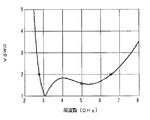
ここで、図9は、図8に示す従来のループアンテナのVSWRの周波数特性を示すグラフ(線図)である。図9において、VSWRは5GHzを中心に約4GHzに亘って2以下を示しており、広帯域特性を有していることが分かる。 Here, FIG. 9 is a graph (diagram) showing the frequency characteristics of the VSWR of the conventional loop antenna shown in FIG. In FIG. 9, VSWR shows 2 or less over about 4 GHz centering on 5 GHz, and it turns out that it has a broadband characteristic.
また、図10は、図8に示す従来のループアンテナの最大利得を示すグラフである。図10において、実線で示されるGxは図8に示すX方向の偏波による利得、破線で示されるGyは図8に示すY方向の偏波による利得である。GxがGyよりも約5dB高い値であり、図8に示す従来のループアンテナの偏波はX方向であることが分かる。 FIG. 10 is a graph showing the maximum gain of the conventional loop antenna shown in FIG. 10, Gx indicated by a solid line is a gain due to polarization in the X direction shown in FIG. 8, and Gy indicated by a broken line is a gain due to polarization in the Y direction shown in FIG. Gx is about 5 dB higher than Gy, and it can be seen that the polarization of the conventional loop antenna shown in FIG. 8 is in the X direction.
一方、図4は、図2に示す本発明のループアンテナのVSWRの周波数特性を示すグラフ(線図)である。図4において、VSWRは5GHzを中心に約4GHzに亘って2以下を示しており、図8に示す従来のループアンテナと同程度の広帯域特性を有していることが分かる。 On the other hand, FIG. 4 is a graph (diagram) showing the frequency characteristics of VSWR of the loop antenna of the present invention shown in FIG. In FIG. 4, VSWR shows 2 or less over about 4 GHz centering on 5 GHz, and it turns out that it has a broadband characteristic comparable as the conventional loop antenna shown in FIG.
また、図5は、図2に示す本発明のループアンテナの最大利得を示すグラフ(線図)である。図5においても、実線で示されるGxは図8に示すX方向の偏波による利得、破線で示されるGyは図2に示すY方向の偏波による利得である。GxがGyよりも約5dB高い値であり、図2に示すループアンテナの偏波はX方向であることが分かる。 FIG. 5 is a graph (diagram) showing the maximum gain of the loop antenna of the present invention shown in FIG. Also in FIG. 5, Gx indicated by a solid line is a gain due to polarization in the X direction shown in FIG. 8, and Gy indicated by a broken line is a gain due to polarization in the Y direction shown in FIG. Gx is about 5 dB higher than Gy, and it can be seen that the polarization of the loop antenna shown in FIG. 2 is in the X direction.
このとき、図8に示す従来のループアンテナの3GHzにおけるGxは2.83dBiであるのに対し、図2に示す本発明のループアンテナの3GHzにおけるGxは5.02dBiと約2.2dB高い値となった。 At this time, Gx at 3 GHz of the conventional loop antenna shown in FIG. 8 is 2.83 dBi, whereas Gx at 3 GHz of the loop antenna of the present invention shown in FIG. 2 is 5.02 dBi, which is about 2.2 dB higher. became.
以上のように、本発明のループアンテナは、元の広帯域ループアンテナの偏波と、各切込み13Aで形成されたアンテナの偏波の全部とが平行なので、元の広帯域ループアンテナによる利得に、各切込み13Aで形成されたアンテナの利得が足されるため、高利得を得ることができることがわかった。
As described above, the loop antenna of the present invention is parallel to the polarization of the original broadband loop antenna and the entire polarization of the antenna formed by the
このとき、すべての切込み13Aが、開口12の長手方向に平行(Y方向)であるため、例えば、開口12の長手方向に垂直な方向(X方向)の切込みにより生じるアンテナの偏波との間で偏波同士が干渉するようなことはなく、より一層効果的に高利得を得ることができた。
At this time, since all the
このループアンテナは、アンテナ導体11に切込み13Aを設けることで高利得を得ることができるので、アンテナ導体11とは別に反射板31を設ける必要がなく、高利得化のために機器が大きくなるということはなく、小型の高利得・広帯域なループアンテナおよび通信機器を実現する上で特に有効なものである。
Since this loop antenna can obtain a high gain by providing the
また、図6は、図3に示す本発明のループアンテナのVSWRの周波数特性を示すグラフ(線図)である。図6において、VSWRは5GHzを中心に約4GHzに亘って2以下を示しており、図8に示す従来のループアンテナと同程度の広帯域特性を有していることが分かる。 FIG. 6 is a graph (diagram) showing the frequency characteristics of VSWR of the loop antenna of the present invention shown in FIG. In FIG. 6, VSWR shows 2 or less over about 4 GHz centering on 5 GHz, and it turns out that it has a broadband characteristic comparable as the conventional loop antenna shown in FIG.
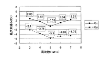
また、図7は、図3に示す本発明のループアンテナの最大利得を示すグラフ(線図)である。図7においても、実線で示されるGxは図8に示すX方向の偏波による利得、破線で示されるGyは図8に示すY方向の偏波による利得である。 FIG. 7 is a graph (diagram) showing the maximum gain of the loop antenna of the present invention shown in FIG. Also in FIG. 7, Gx indicated by a solid line is a gain due to polarization in the X direction shown in FIG. 8, and Gy indicated by a broken line is a gain due to polarization in the Y direction shown in FIG.
このとき、図8に示す従来のループアンテナの3GHzにおけるGyは−2.1dBiであるのに対し、図5に示す本発明のループアンテナの3GHzにおけるGyは4.32dBiと約6dB高い値となり、3GHzにおいてはX方向の偏波と同ように、Y方向の偏波も送受可能である。 At this time, Gy at 3 GHz of the conventional loop antenna shown in FIG. 8 is −2.1 dBi, whereas Gy at 3 GHz of the loop antenna of the present invention shown in FIG. 5 is 4.32 dBi, which is about 6 dB higher, At 3 GHz, the polarization in the Y direction can be transmitted and received in the same manner as the polarization in the X direction.
以上のように、本発明のループアンテナは、元の広帯域ループアンテナの偏波と、各切込み13Bで形成されたアンテナの偏波の全部とが直交するので、元の広帯域ループアンテナに対応した偏波Gxと、各切込み13Bで形成されたアンテナに対応した互いに直交する偏波Gyの双方を送受信可能となり、あらゆる偏波に対応、すなわち偏波共用できることがわかった。
As described above, in the loop antenna according to the present invention, the polarization of the original broadband loop antenna and the entire polarization of the antenna formed by the
このとき、すべての切込み13Bが、開口12の長手方向に垂直(X方向)であるため、例えば、開口の長手方向に平行な方向(Y方向)の切込みにより生じるアンテナの偏波との間で偏波同士が干渉するようなことはなく、より一層効果的に偏波共用効果を得ることができた。
At this time, since all the
このループアンテナは、アンテナ導体11に切込み13Bを設けることで偏波共用できるので、基本となる1方向の偏波に対応したアンテナを向きを変えて複数個設けるといった一般的な偏波共用手法のように、アンテナ導体11を複数個設ける必要がなく、偏波共用化のために機器が大きくなるということはなく、小型の偏波共用・広帯域なループアンテナおよび通信機器を実現する上で特に有効なものである。
Since this loop antenna can share the polarization by providing the
以上のように、中央部に帯状の開口12を有する平面状のアンテナ導体11と、アンテナ導体11の一端部に、開口12の長手方向の延長線上に位置するようにして形成された給電回路21とを備えるループアンテナにおいて、アンテナ導体11の外縁部に切込み13Bを設けることで、小型で、利得が高く、偏波共用の広帯域なループアンテナを提供することができた。
As described above, the
このループアンテナが送信や受信用の装置として搭載されることにより、携帯電話や無線LAN、テレビ等の無線通信機器、その他の各種の通信機器が製作される。 By mounting this loop antenna as a device for transmission and reception, a wireless communication device such as a mobile phone, a wireless LAN, and a television, and other various communication devices are manufactured.
この通信機器によれば、上記本発明のループアンテナが搭載されていることから、高利得化のための反射板や、偏波共用のためのアンテナ導体が不要なため、小型の通信機器を提供することができる。 According to this communication device, since the loop antenna of the present invention is mounted, there is no need for a reflector for increasing the gain and an antenna conductor for sharing the polarization, thereby providing a small communication device. can do.
ループアンテナは、例えば、ループアンテナの給電回路21を電気的に接続させるための端子を設けた基板に実装された後、その基板が高周波回路、デジタル回路、表示パネル等のインターフェイスを構成する筐体内に収納されて搭載される。
For example, after the loop antenna is mounted on a substrate provided with a terminal for electrically connecting the
なお、この場合、アンテナ導体11や開口12は長方形状、また開口12は楕円形状としてもよく、機器の筐体形状に合せた構造とすることができる。
In this case, the
例えば、このループアンテナを携帯型テレビ受像機に使う場合、アンテナ導体11がWメタライズ層で形成され、さらに高周波回路が実装された誘電体基板を、筐体の形状に合せたものとすることで、筐体内に反射板が不要で、筐体の寸法を小型に保ちながら最大限に利用した通信機器を実現することができる。
For example, when this loop antenna is used for a portable television receiver, a dielectric substrate in which the
なお、本発明は上記実施の形態の例に限定されず、本発明の要旨の範囲内であれば種々の変更を施すことができる。 In addition, this invention is not limited to the example of the said embodiment, A various change can be given if it is in the range of the summary of this invention.
たとえば、切込み13A,13Bの長さや数を種々のものとしてもよい。切込み13A,13Bの長さによって切込み13A,13Bで形成されたアンテナの動作周波数が決まるので、種々の長さを有する切込み13A,13Bを配することで種々の周波数において利得の向上、偏波共用効果を得ることができる。
For example, the lengths and numbers of the
また、切込み13A,13Bの形状は、L字、T字、ミアンダ形状としてもよく、そのような形状にすることでより切込み13A,13Bの電気的な長さを長くすることができ、切込み13A,13Bで形成されたアンテナの動作共振周波数を大きく変化させることができる。
Further, the shapes of the
11・・・アンテナ導体
12・・・開口
13・・・切込み
21・・・給電回路
11 ...
Claims (6)
Priority Applications (1)
| Application Number | Priority Date | Filing Date | Title |
|---|---|---|---|
| JP2005333741A JP4570552B2 (en) | 2005-11-18 | 2005-11-18 | Loop antenna and communication equipment |
Applications Claiming Priority (1)
| Application Number | Priority Date | Filing Date | Title |
|---|---|---|---|
| JP2005333741A JP4570552B2 (en) | 2005-11-18 | 2005-11-18 | Loop antenna and communication equipment |
Publications (2)
| Publication Number | Publication Date |
|---|---|
| JP2007142796A JP2007142796A (en) | 2007-06-07 |
| JP4570552B2 true JP4570552B2 (en) | 2010-10-27 |
Family
ID=38205121
Family Applications (1)
| Application Number | Title | Priority Date | Filing Date |
|---|---|---|---|
| JP2005333741A Expired - Fee Related JP4570552B2 (en) | 2005-11-18 | 2005-11-18 | Loop antenna and communication equipment |
Country Status (1)
| Country | Link |
|---|---|
| JP (1) | JP4570552B2 (en) |
Families Citing this family (12)
| Publication number | Priority date | Publication date | Assignee | Title |
|---|---|---|---|---|
| JP4841398B2 (en) * | 2006-10-27 | 2011-12-21 | 京セラ株式会社 | Loop antenna, antenna board, antenna integrated module and communication device |
| WO2009041497A1 (en) * | 2007-09-28 | 2009-04-02 | Nec Corporation | Loop antenna |
| JP4811807B2 (en) * | 2007-11-13 | 2011-11-09 | 国立大学法人九州大学 | Antenna, antenna design apparatus, antenna design method, and method for producing antenna |
| JP4922984B2 (en) * | 2008-04-03 | 2012-04-25 | 株式会社日立製作所 | RFID antenna and RFID tag |
| US7876227B2 (en) * | 2008-05-29 | 2011-01-25 | Symbol Technologies, Inc. | Polarization insensitive antenna for handheld radio frequency identification readers |
| ITMI20081206A1 (en) * | 2008-06-30 | 2010-01-01 | Maurizio Stasolla | QUAD ANTENNA |
| CN104362424B (en) * | 2008-11-17 | 2018-09-21 | 株式会社村田制作所 | Wireless telecom equipment |
| JP5294067B2 (en) * | 2009-02-27 | 2013-09-18 | 日本電気株式会社 | antenna |
| JP2010251998A (en) * | 2009-04-14 | 2010-11-04 | Takahashi Hitoshi | Antenna |
| JP2011004392A (en) * | 2009-05-20 | 2011-01-06 | Hitachi Chem Co Ltd | Antenna |
| JP2018201080A (en) * | 2017-05-25 | 2018-12-20 | 富士通株式会社 | Antenna device, and electronic equipment |
| CN113300086B (en) * | 2021-05-18 | 2023-07-14 | 北京有竹居网络技术有限公司 | Finger ring |
Citations (3)
| Publication number | Priority date | Publication date | Assignee | Title |
|---|---|---|---|---|
| JPS4522325Y1 (en) * | 1970-04-13 | 1970-09-04 | ||
| JP2000165134A (en) * | 1998-11-25 | 2000-06-16 | Nec Corp | Patch antenna |
| JP2002246821A (en) * | 2001-02-14 | 2002-08-30 | Takahashi Hitoshi | Plate antenna and portable communication terminal equipped with the same and broadcast receiver |
-
2005
- 2005-11-18 JP JP2005333741A patent/JP4570552B2/en not_active Expired - Fee Related
Patent Citations (3)
| Publication number | Priority date | Publication date | Assignee | Title |
|---|---|---|---|---|
| JPS4522325Y1 (en) * | 1970-04-13 | 1970-09-04 | ||
| JP2000165134A (en) * | 1998-11-25 | 2000-06-16 | Nec Corp | Patch antenna |
| JP2002246821A (en) * | 2001-02-14 | 2002-08-30 | Takahashi Hitoshi | Plate antenna and portable communication terminal equipped with the same and broadcast receiver |
Also Published As
| Publication number | Publication date |
|---|---|
| JP2007142796A (en) | 2007-06-07 |
Similar Documents
| Publication | Publication Date | Title |
|---|---|---|
| JP4570552B2 (en) | Loop antenna and communication equipment | |
| JP5293181B2 (en) | ANTENNA DEVICE AND RADIO COMMUNICATION DEVICE USING THE SAME | |
| US20070236394A1 (en) | Antenna device and wireless communication apparatus using same | |
| JP2008028734A (en) | Surface mounting antenna and communication apparatus mounting it | |
| WO2001076007A1 (en) | Wide beamwidth ultra-compact antenna with multiple polarization | |
| WO2004100312A1 (en) | Antenna integrated into a housing | |
| JP2005086788A (en) | Surface-mounted antenna, antenna device and radio communication apparatus | |
| JP2003298339A (en) | Stacked dielectric antenna | |
| JPH07303005A (en) | Antenna system for vehicle | |
| US20110148715A1 (en) | Patch antenna and miniaturizing method thereof | |
| WO2004025781A1 (en) | Loop antenna | |
| JPH11274845A (en) | Antenna system | |
| JPH05243837A (en) | Slot antenna | |
| TWI228845B (en) | Cable antenna apparatus | |
| JP2007174153A (en) | Loop antenna and communication apparatus | |
| JP4195038B2 (en) | Dual band antenna | |
| JP2007124181A (en) | Rf circuit module and mobile communication device | |
| JP2007124346A (en) | Antenna element and array type antenna | |
| JPH10256818A (en) | Antenna system and its mounting structure | |
| JP3880295B2 (en) | Chip antenna | |
| JPH10327012A (en) | Antenna system and how to use the antenna system | |
| JP4841398B2 (en) | Loop antenna, antenna board, antenna integrated module and communication device | |
| JP2010239496A (en) | Planar antenna | |
| JP4659728B2 (en) | Loop antenna, antenna board, antenna integrated module and communication device | |
| JP3735582B2 (en) | Multilayer dielectric antenna |
Legal Events
| Date | Code | Title | Description |
|---|---|---|---|
| A621 | Written request for application examination |
Free format text: JAPANESE INTERMEDIATE CODE: A621 Effective date: 20080519 |
|
| A977 | Report on retrieval |
Free format text: JAPANESE INTERMEDIATE CODE: A971007 Effective date: 20100301 |
|
| A131 | Notification of reasons for refusal |
Free format text: JAPANESE INTERMEDIATE CODE: A131 Effective date: 20100427 |
|
| A521 | Written amendment |
Free format text: JAPANESE INTERMEDIATE CODE: A523 Effective date: 20100625 |
|
| TRDD | Decision of grant or rejection written | ||
| A01 | Written decision to grant a patent or to grant a registration (utility model) |
Free format text: JAPANESE INTERMEDIATE CODE: A01 Effective date: 20100713 |
|
| A01 | Written decision to grant a patent or to grant a registration (utility model) |
Free format text: JAPANESE INTERMEDIATE CODE: A01 |
|
| A61 | First payment of annual fees (during grant procedure) |
Free format text: JAPANESE INTERMEDIATE CODE: A61 Effective date: 20100810 |
|
| FPAY | Renewal fee payment (event date is renewal date of database) |
Free format text: PAYMENT UNTIL: 20130820 Year of fee payment: 3 |
|
| R150 | Certificate of patent or registration of utility model |
Free format text: JAPANESE INTERMEDIATE CODE: R150 |
|
| LAPS | Cancellation because of no payment of annual fees |