JP4565621B2 - Information processing system - Google Patents
Information processing system Download PDFInfo
- Publication number
- JP4565621B2 JP4565621B2 JP2004191459A JP2004191459A JP4565621B2 JP 4565621 B2 JP4565621 B2 JP 4565621B2 JP 2004191459 A JP2004191459 A JP 2004191459A JP 2004191459 A JP2004191459 A JP 2004191459A JP 4565621 B2 JP4565621 B2 JP 4565621B2
- Authority
- JP
- Japan
- Prior art keywords
- input
- authentication
- data
- pointing
- memory medium
- Prior art date
- Legal status (The legal status is an assumption and is not a legal conclusion. Google has not performed a legal analysis and makes no representation as to the accuracy of the status listed.)
- Expired - Fee Related
Links
Images


Landscapes
- Storage Device Security (AREA)
- Position Input By Displaying (AREA)
Description
本発明は、例えば表示装置と一体的に形成された座標入力装置を有する情報処理システムに関する。 The present invention relates to an information processing system having a coordinate input device formed integrally with a display device, for example.
座標入力装置は、コンピュータの表示装置である例えばCRT,液晶ディスプレイ、あるいはプラズマディスプレイ等の画像表示面と一体的に重ね合わせて構成され、これにより表示画面に直接描画やポインティング等の操作を行うことでコンピュータへの入力を可能にするものである。このような座標入力装置は、入力指示器の位置を検出するための物理現象に基づく検出原理により分類される各種の方式が知られている。主な方式としては、抵抗タブレット方式,磁気結合タブレット方式,容量結合タブレット方式,光結合タブレット方式,音響・振動タブレット方式等がある。抵抗タブレット方式については例えば特開平5−53715号公報(特許文献1)、磁気結合タブレット方式については例えば特開平5−289806号公報(特許文献2)、容量結合タブレット方式については例えば特開平5−80921号公報(特許文献3)、光結合タブレット方式については例えば特開平5−53717号公報(特許文献4)、音響・振動タブレット方式については例えば特開平5−66877号公報(特許文献5)に開示されている。 The coordinate input device is configured to overlap with an image display surface such as a computer display device such as a CRT, a liquid crystal display, or a plasma display, thereby performing operations such as direct drawing and pointing on the display screen. This allows input to a computer. Various types of such coordinate input devices are known that are classified based on a detection principle based on a physical phenomenon for detecting the position of an input indicator. The main methods include resistance tablet method, magnetic coupling tablet method, capacitive coupling tablet method, optical coupling tablet method, and sound / vibration tablet method. For example, Japanese Unexamined Patent Publication No. 5-53715 (Patent Document 1) for the resistance tablet system, Japanese Unexamined Patent Publication No. 5-289806 (Patent Document 2) for the magnetic coupling tablet system, and Japanese Patent Laid-Open No. No. 80921 (Patent Document 3), optical coupling tablet system, for example, JP-A-5-53717 (Patent Document 4), and acoustic / vibration tablet system, for example, JP-A-5-66877 (Patent Document 5). It is disclosed.
タブレットのサイズは、小型のものでは鞄等に入れて持ち運べる個人向けの携帯サイズから、大型のものではいわゆる電子黒板サイズまで、各種のサイズがある。タブレットを有する情報処理装置においては、操作者がペン型の入力指示器を入力板に近づけるか又は当接すると、そのペンの位置座標、すなわち入力点が検出され、この検出結果に基づいて所定の機能、例えばメニューコマンドの実行等が行われる。 There are various sizes of tablets ranging from a portable size for individuals that can be carried in a bag for small ones, to a so-called electronic blackboard size for large ones. In an information processing apparatus having a tablet, when an operator brings a pen-type input indicator close to or in contact with an input board, the position coordinates of the pen, that is, an input point is detected, and a predetermined value is determined based on the detection result. Functions such as execution of menu commands are performed.
一方では入力指示器としてマウスを用いて、表示装置に表示されるカーソルを制御する一般的なコンピュータの使用形態がある。近年では、光学式マウスが主流となってきていて、従来のトラッキングボールがマウス内にないため、マウス全体がやや軽量であるとともに、ボールの掃除などが不要であることから、ボール式のマウスに比べ利点が多い。さらにメモリーカードインタフェースをマウスに内蔵することで、通常のマウス機能の他、メモリーカード内のデータを手軽に読み書きできる外部記憶装置として使用できるものもある。メモリーカード装着後は、リムーバブルディスクとしてデータの読み書きが可能となっている。 On the other hand, there is a general use form of a computer that controls a cursor displayed on a display device using a mouse as an input indicator. In recent years, optical mice have become mainstream, and since the conventional tracking ball is not in the mouse, the entire mouse is slightly lighter and requires no ball cleaning. There are many advantages. Furthermore, by incorporating a memory card interface in the mouse, there are some that can be used as an external storage device that can easily read and write data in the memory card in addition to the normal mouse function. After the memory card is installed, data can be read and written as a removable disk.
これらの装置において、例えば特開平7−28585号公報(特許文献6)では、入力指示器であるペンを個人情報を記憶する外部記憶装置として利用できるようにし、ペン入力コンピュータの携帯性および操作性の向上を図ることを目的とする提案がなされている。同文献には、ペン入力コンピュータで認識率を高めるために個人辞書を利用した文字認識機能について記載されており、スタイラスペンに不揮発性のフラッシュメモリが搭載されており、そのフラッシュメモリに個人辞書等の各種データを記憶することができる。 In these devices, for example, in Japanese Patent Application Laid-Open No. 7-28585 (Patent Document 6), a pen as an input indicator can be used as an external storage device for storing personal information, and portability and operability of a pen input computer can be used. Proposals have been made for the purpose of improving the above. This document describes a character recognition function that uses a personal dictionary to increase the recognition rate with a pen input computer, and the stylus pen is equipped with a non-volatile flash memory. The various data can be stored.
また、特開平4−205821号公報(特許文献7)には、マルチメディア情報をコンピュータに入力するマルチメディア情報入力装置に係わり、特に電子スチルカメラで撮影した画像情報や、マイクロフォンで入力した音声をコンピュータに電子化入力する装置に関し、操作性を向上させることを目的として、表示装置と手書き入力を行う座標入力装置を一体化した入力表示一体化タブレットと、少なくとも、撮像装置と、該撮像した画像信号をデジタル信号に変換する画像信号処理回路、音声を入力するマイクロフォンと、入力した音声をデジタル信号に変換する音声信号処理回路を内蔵した手書き入力用スタイラスペンとから構成する提案がなされている。 Japanese Patent Application Laid-Open No. 4-205821 (Patent Document 7) relates to a multimedia information input device that inputs multimedia information to a computer. In particular, image information captured by an electronic still camera and audio input by a microphone are used. The present invention relates to an apparatus for electronically inputting to a computer. For the purpose of improving operability, an input display integrated tablet in which a display apparatus and a coordinate input apparatus for performing handwriting input are integrated, at least an imaging apparatus, and the captured image Proposals have been made of an image signal processing circuit that converts a signal into a digital signal, a microphone that inputs sound, and a stylus pen for handwriting input that includes a sound signal processing circuit that converts input sound into a digital signal.
さらには、特開平6−282375号公報(特許文献8)には、ペン操作だけである情報処理装置から別の情報処理装置へデータを転送できるようにすることを目的として、一方のペンコンピュータの表示装置に表示されている画面の中で転送したいデータを所定のストロークのペン操作により指定およびペン内のメモリに保存し、次に、別のペンコンピュータの表示装置の表示画面において所定のストロークのペン操作によりこの表示画面内での上記指定データの上書き位置または挿入位置を指定し、無線でデータ送信を行う提案がなされている。 Furthermore, Japanese Patent Laid-Open No. 6-282375 (Patent Document 8) discloses that one pen computer can be used to transfer data from an information processing apparatus that is only operated by a pen to another information processing apparatus. Data to be transferred in the screen displayed on the display device is designated by pen operation of a predetermined stroke and stored in the memory in the pen, and then the data of the predetermined stroke is displayed on the display screen of the display device of another pen computer. There has been a proposal for transmitting data wirelessly by designating an overwrite position or insertion position of the designated data in the display screen by a pen operation.
従来の情報処理装置において、可搬性のある記憶媒体の操作性に関しては、以下のような問題がある。 The conventional information processing apparatus has the following problems regarding the operability of the portable storage medium.
すなわち、コンピュータの周辺ポート(例えばUSB)に接続して使用する例えばフラッシュメモリをリムーバルメディアとして機能させる機器は、たとえホスト装置がネットワークに接続できない環境であったとしても、可搬性に優れ且つデータを記憶可能な媒体として手軽にデータ転送が可能であるという利点はあるものの、記憶内容のファイルをいざ使用するときには所定の手順を踏まなければならず、必ずしも操作性に優れているとは言えなかった。 That is, a device that uses a flash memory, for example, that is connected to a peripheral port (for example, USB) of a computer and functions as a removable medium has excellent portability and data even if the host device cannot be connected to a network. Although there is an advantage that data can be easily transferred as a storable medium, it is not always excellent in operability because a predetermined procedure must be taken when using a file with stored contents. .
例えば、従来の装置は、ポートに接続し、認証を行ないドライブとして認識されるのと同時にドライバやプロファイル情報が本体にロードされて初めてメモリ内のファイルへのアクセス可能な状態になる。その後ユーザーは、ウィンドウシステムを操作してメモリの内容を表示させて所望の動作を開始するまでに数回のウィンドウ操作が必要である。 For example, a conventional apparatus is connected to a port, performs authentication, and is recognized as a drive. At the same time, a driver and profile information are loaded into the main body, and a file in a memory can be accessed. Thereafter, the user needs to operate the window several times before operating the window system to display the contents of the memory and starting a desired operation.
また、この種の情報処理装置を大画面の表示装置で構成し会議システムなどとして利用する場合には、特に複数人が使用する形態を考えたとき、使用者が各ポートに各々のメモリを接続して使用する状況が考えられるが、コンピュータのポート数には制限があり、現実的には複数の使用者のメモリを同時に接続して使用する状況はほとんどないといってもよい。 In addition, when this type of information processing device is configured as a large-screen display device and used as a conference system, the user connects each memory to each port, especially when considering the form used by multiple people However, the number of ports of the computer is limited, and in reality, it may be said that there are almost no situations in which a plurality of users' memories are connected and used at the same time.
したがって、複数人で使用する場合は、いちいちログインしなおしたり、ドライブとして認識した後に、ウィンドウシステムでファイルの一覧を見るためには、各々がポートに接続しなおしたり、操作者が交替してウィンドウシステムを操作するなど、操作が煩雑であり、簡単に利用できるとは言いがたいものである。 Therefore, if you want to use more than one person, log in again or recognize it as a drive, and then to view the list of files in the window system, reconnect to each port or change the window. It is difficult to say that the operation is complicated and easy to use, such as operating the system.
さらに、前述のような従来の座標入力装置を備えた情報処理装置においては、情報処理装置で扱うデータの安全性に関わる以下のような問題がある。 Furthermore, in the information processing apparatus provided with the conventional coordinate input apparatus as described above, there are the following problems related to the safety of data handled by the information processing apparatus.
すなわち、記憶媒体から情報処理装置へのデータ転送または情報処理装置から記憶媒体へのデータ転送を行なう際のアクセスなどの権限、さらには、転送後データに対するアクセスなどの権限に関する問題である。 That is, there is a problem relating to authority such as access when performing data transfer from the storage medium to the information processing apparatus or data transfer from the information processing apparatus to the storage medium, and authority such as access to post-transfer data.
特に前述の装置を会議システムに応用した場合に、該装置を会議室に常設した場合など使用者が限定されておらず、不特定多数の使用者が存在する場合のように、使用する情報処理装置が共有の装置となる場合は、不正アクセス、データの改ざん、閲覧許可やアクセス許可などのユーザーアクセス制限、コピー禁止などのファイルセキュリティなどの様々なデータの安全性を考慮すべきである。 In particular, when the above-mentioned device is applied to a conference system, the user is not limited, such as when the device is permanently installed in a conference room, and the information processing to be used is present when there are a large number of unspecified users. When the device is a shared device, the safety of various data such as unauthorized access, falsification of data, user access restrictions such as browsing permission and access permission, and file security such as copy prohibition should be considered.
一方で、座標入力装置の指示機器にフラッシュメモリを搭載することで、可搬性のある外部記憶装置となることから、置き忘れ等により他人にメモリ内のデータを使用される可能性もある。また、本体情報処理装置にデータ転送して使用する場合でも、特定の人だけにのみアクセス可能にしたい場合など、機密情報やプライバシー情報など重要な資料や人に見られたくない資料がある場合は、複製を禁止したり、アクセス自体を禁止したい。 On the other hand, by installing a flash memory in the pointing device of the coordinate input device, it becomes a portable external storage device. Therefore, there is a possibility that data in the memory may be used by others due to misplacement or the like. In addition, even when transferring data to the main unit information processing device and using it, if there is important material such as confidential information or privacy information that you do not want to be seen by people, such as when you want to make it accessible only to specific people I want to prohibit duplication or access itself.
上記の複数の問題に対し、先述の特許文献6、特許文献7、特許文献8には、記憶手段に保存されているファイルの閲覧性および操作性については何ら言及されておらず、従来の技術では、使用者にとっては極めて不便な操作を強いてしまうという問題が解消されるものではない。さらに、これらの文献では情報処理装置で扱う情報の安全性についても何らの示唆されておらず、上記の問題を何ら回避できるものではない。
With respect to the above problems, Patent Document 6,
本発明は、このような状況のもとでなされたもので、座標入力装置の指示手段とホスト装置間での各種データを扱う場合の操作性および該データの安全性を向上させた情報処理システムを提供することを目的とする。 The present invention has been made under such circumstances, and is an information processing system that improves the operability and the safety of the data when handling various data between the instruction means of the coordinate input device and the host device. The purpose is to provide.
本発明の一側面は、画像を表示する表示装置と、データの書き換えが可能なメモリ媒体を備えた指示具と、前記表示装置による画像の表示面に設けた入力領域内における前記指示具による操作に係る情報を入力する入力装置と、前記入力装置によって入力された情報に応じた制御処理を行うホスト装置とを有する情報処理システムに係わる。ここで、前記入力装置は、前記指示具の所定の操作によって発行される前記メモリ媒体−前記ホスト装置間におけるファイル転送の要求を検出した場合に、前記メモリ媒体に対するアクセスのための認証を行う認証モードの動作を行うか否かを、前記ホスト装置からの信号に基づいて判断する判断手段と、前記判断手段により前記認証モードの動作を行うと判断された場合に、前記指示具により入力された情報を認証用データに変換する変換手段と、前記変換手段により得られた前記認証用データを前記指示具に送信する送信手段とを有する。一方、前記指示具は、前記入力装置より受信した前記認証用データに基づき認証処理を行う認証手段を有する。 One aspect of the present invention is a display device that displays an image, an indicator that includes a rewritable memory medium, and an operation performed by the indicator in an input area provided on an image display surface by the display device. The present invention relates to an information processing system including an input device that inputs information related to the above and a host device that performs control processing according to the information input by the input device. Here, the input device, wherein the memory medium is issued by a predetermined operation of the pointing device - when it detects a request for file transfer between the host device performs the authentication for access to said memory medium A determination unit that determines whether or not to perform an authentication mode operation based on a signal from the host device, and when the determination unit determines that the authentication mode operation is to be performed, is input by the indicator. has been a conversion unit information is converted into authentication data, and transmitting means for transmitting the authentication data obtained by the conversion means to the pointing device. On the other hand, the pointing device includes an authentication unit that performs an authentication process based on the authentication data received from the input device.
本発明によれば、座標入力装置の指示手段とホスト装置間での各種データを扱う場合の操作性および該データの安全性を向上させた情報処理システムを提供することができる。 ADVANTAGE OF THE INVENTION According to this invention, the information processing system which improved the operativity at the time of handling various data between the instruction | indication means of a coordinate input device and a host apparatus, and the safety | security of this data can be provided.
以下、図面を参照して本発明の好適な実施形態について詳細に説明する。 DESCRIPTION OF EMBODIMENTS Hereinafter, preferred embodiments of the present invention will be described in detail with reference to the drawings.
(座標入力装置の概略構成)
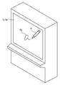
まず、本実施形態における情報処理システムの概略構成を図1A、図1Bを用いて説明する。図1Aは実施形態における情報処理システムの画像表示・入力部の外観斜視図、図1Bはこの情報処理システムのハードウェア構成を示すブロック図である。
(Schematic configuration of coordinate input device)
First, a schematic configuration of the information processing system in the present embodiment will be described with reference to FIGS. 1A and 1B. FIG. 1A is an external perspective view of an image display / input unit of the information processing system in the embodiment, and FIG. 1B is a block diagram showing a hardware configuration of the information processing system.
この情報処理システムは、画像を表示する表示装置としてのプロジェクター7、このプロジェクター7の画像表示面7a上に設けられる座標入力装置8、プロジェクター7および座標入力装置8にそれぞれ接続され、両者を制御する制御装置(ホスト装置)としてのホストコンピュータ6を含む構成である。ホストコンピュータ6は例えばパーソナルコンピュータ(PC)によって実現されるものである。したがって、プロジェクター7および座標入力装置8はそれぞれ、例えばUSBなどのインタフェースを介してホストコンピュータ6に接続されうる。
This information processing system is connected to and controls a
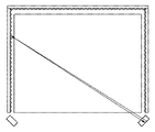
座標入力装置8の構成について説明すると、図1Bにおける1L、1Rはそれぞれ、投光器および検出器を有するセンサユニットであり、1Lと1Rとは互いに所定の距離だけ離れた位置に設置されている。センサユニット1L、1Rは、制御・演算を行う制御・演算ユニット2に接続され、制御信号を制御・演算ユニット2から受け取ると共に、検出した信号を制御・演算ユニット2に送信する。3は、図2のように入射光を到来方向に反射する再帰反射面を有する反射部材であり、左右それぞれのセンサユニットから入力領域5の面に沿ってその入力領域5を覆う範囲(例えば略90°の範囲)に投光された光を、センサユニットに向けて再帰反射する。反射光は、集光光学系とラインCCD等によって構成されたセンサユニットの検出器によって1次元的に検出され、その光量分布が制御・演算ユニット2に送られる。
The configuration of the coordinate
入力領域5は、PDPやリアプロジェクタ、LCDパネルなどの表示装置の表示画面上に構成されることで、インタラクティブな入力装置として利用可能となっている。このシステムでは、所定の指示具4を入力領域5に押圧等し移動させることで軌跡4aの入力が可能であり、また、表示されるアイコンなどの様々な情報に対して指示入力することで、各種アプリケーションのコントロールが可能となっている。
The
このような構成において、入力領域に指示具4あるいは指などによる入力指示がなされると、上記投光器から投光された光が遮られ、再帰反射による反射光が得られなくなるため、入力指示位置のみ光量が得られなくなる。
In such a configuration, when an input instruction is given to the input area with the
制御・演算ユニット2は、左右のセンサユニット1L、1Rの光量変化から、入力指示された部分の遮光範囲を検出し、同範囲内での検出点を特定してそれぞれの角度を算出する。算出された角度および、センサユニット間の距離等から、入力領域5上の座標位置を算出し、ホストコンピュータ6にその座標値を出力する。
The control /
このようにして、指などによって、画面上に線を描画したり、アイコンの操作するなどホストコンピュータ6の操作が可能になる。 In this way, the host computer 6 can be operated with a finger or the like to draw a line on the screen or operate an icon.
以下、座標入力装置8の各部分毎についての詳細説明を行う。
Hereinafter, each part of the coordinate
(センサユニットの詳細説明)
図3は、センサユニット1L、1Rにおける投光器の構成例を示す図で、(A)は投光器を上から(入力面に対し垂直方向)から見た図、(B)は横(入力面に対し水平方向)から見た図である。31は赤外光を発する赤外LEDであり、発光した光は投光レンズ32によって、略90°範囲に光が射出する。この方向では、赤外LED31からの光は上下方向に制限された光束として投光され、主に反射器3に対して光が投光されるようになっている。
(Detailed explanation of sensor unit)
3A and 3B are diagrams showing a configuration example of a projector in the
図4は、センサユニット1L、1Rにおける検出器を入力面に対して垂直方向から見た図である。検出器は、1次元のラインCCD41および集光光学系としてのレンズ42,43および、入射光の入射方向を制限する絞り44、可視光など余分な光の入射を防止する赤外フィルター45を有する構成である。
FIG. 4 is a diagram of the detectors in the
投光器からの光は再帰反射部材によって反射され、赤外フィルター45、絞り44を抜けて、集光用レンズ42,43によって入力面の略90°範囲の光がCCD41の検出面にその入射角に依存した画素上に結像され、角度ごとの光量分布を示す。つまり画素番号が角度情報を表すことになる。
The light from the projector is reflected by the retroreflective member, passes through the
図5は、入力面を水平方向からの見たときのセンサユニット1L、1Rの構成を示している。図示のように、上記投光器と検出器とが重なるように構成されている。投光器と検出器の光軸間の距離は再帰反射部材の角度特性から充分検出可能な範囲に設定されていればよい。
FIG. 5 shows the configuration of the
(反射部材について)
図1に示した再帰性反射部材3は、入射角度に対する反射特性を有している。図6に示す入射角度に対する反射光量の特性図からわかるように、再帰性反射部材3が平坦に構成された場合には、反射部材からの角度が45度を超えるあたりから得られる反射光量が減少し、遮蔽物があった場合にその変化が十分に取れないことになる。
(Reflecting member)
The
反射光量は、光量分布(照明強度および距離)、反射部材の反射率(入射角度、反射部材の幅)、結像系照度(cosine4乗則)によって決まる。光量が足りない場合に、照明強度を上げることが考えられるが、反射分布が均一で無い場合には、強い部分の光を受光したときに、受光手段であるCCDでその部分が飽和することがあり、照明強度を上げるには限界がある。裏返せば、反射部材の反射の分布をなるべく均一にすることで低光量部分への入射光量の増大も望むことができる。 The amount of reflected light is determined by the light amount distribution (illumination intensity and distance), the reflectance of the reflecting member (incident angle, the width of the reflecting member), and the imaging system illuminance (cosine fourth law). When the amount of light is insufficient, it is conceivable to increase the illumination intensity. However, if the reflection distribution is not uniform, when a strong portion of light is received, the portion may be saturated by the CCD as the light receiving means. There is a limit to increasing the illumination intensity. In other words, it is also possible to increase the amount of light incident on the low light amount portion by making the reflection distribution of the reflecting member as uniform as possible.
角度方向に対して均一化を図るために、再帰性反射部材3を貼り付ける部材を図7に示すような三角柱を並べた形とし、この上に再帰反射部材3を設置している。これにより、角度特性を改善することができる。なお、三角柱の角度は再帰反射部材の反射特性から決定すればよく、また、そのピッチはCCDでの検出分解能以下に設定するのが望ましい。
In order to make the angle direction uniform, the member to which the
(制御・演算ユニットの説明)
図1に示した制御・演算ユニット2とセンサユニット1L,1Rとの間では、CCDの制御信号、CCD用クロック信号とCCDの出力信号、および、LEDの駆動信号がやり取りされている。
(Explanation of control / arithmetic unit)
A CCD control signal, a CCD clock signal and a CCD output signal, and an LED drive signal are exchanged between the control /
図8は、制御・演算ユニット2の構成を示すブロック図である。CCD制御信号は、ワンチップマイコンなどで構成される演算制御回路(CPU)83から出力されており、CCDのシャッタタイミングや、データの出力制御などを行っている。CCD用のクロックはクロック発生回路87からセンサユニット1L、1Rに送られると共に、CCDとの同期をとって、各種制御を行うために、演算制御回路83にも入力されている。
FIG. 8 is a block diagram showing the configuration of the control /
LED駆動信号は、演算制御回路83からLED駆動回路84L,84Rを経て、センサユニット1L、1Rの赤外LEDに供給されている。
The LED drive signal is supplied from the
センサユニット1L、1Rの検出器におけるCCDからの検出信号は、A/Dコンバータ81L,81Rに入力され、演算制御回路83からの制御によって、デジタル値に変換される。変換されたデジタル値はメモリ(例えばRAM)82に記憶され、角度計算に用いられる。計算された角度から座標値が求められると、その座標値データがホストコンピュータ6に出力される。
Detection signals from the CCDs in the detectors of the
(光量分布検出の説明)
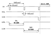
図9は、LED発光に係る各制御信号のタイミングチャートである。
(Explanation of light intensity distribution detection)
FIG. 9 is a timing chart of each control signal related to LED light emission.
信号SH、ICGL、ICGRはCCD制御用の制御信号であり、SHの間隔でCCDのシャッタ解放時間が決定される。信号ICGL、ICGRはそれぞれ左右のセンサユニット1L,1Rへのゲート信号であり、CCD内部の光電変換部の電荷を読み出し部へ転送する信号である。信号LEDL、LEDRはそれぞれ、左右のLEDの駆動信号であり、SHの最初の周期で一方のLEDを点灯するために駆動信号LEDLがLED駆動回路を経てLEDに供給される。次の周期でもう一方のLEDが駆動される。双方のLEDの駆動が終了した後に、CCDの信号が左右のセンサから読み出される。
Signals SH, ICGL, and ICGR are control signals for CCD control, and the shutter release time of the CCD is determined by the interval of SH. Signals ICGL and ICGR are gate signals to the left and
読み出される信号は、入力がない場合には、それぞれのセンサからの出力として、図10のような光量分布が得られる。もちろん、このような分布がどのシステムでも必ず得られるわけではなく、再帰性反射部材3の特性やLEDの特性、また、経時変化(反射面の汚れなど)によって分布は変化する。同図においては、Aのレベルが最大光量であり、Bのレベルが最低のレベルとなる。つまり反射光のない状態では、得られるレベルがB付近になり、反射光量が増えるほどAのレベルの方向になっている。このようにCCDから出力されたデータは、逐次AD変換されCPUにデジタルデータとして取り込まれる。
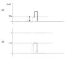
When the signal to be read is not input, a light amount distribution as shown in FIG. 10 is obtained as an output from each sensor. Of course, such a distribution is not necessarily obtained in any system, and the distribution changes depending on the characteristics of the
図11は、指などで入力を行った、つまり、反射光を遮った場合の出力の例である。Cの部分が指などで反射光が遮られたため、その部分のみ光量が低下している。検出は、この光量分布の変化から行う。具体的には、図10のような入力の無い初期状態を予め記憶しておいて、それぞれのサンプル期間に図11のような変化があるか初期状態との差分によって検出し、変化があったらその部分を入力点として入力角度を決定する演算を行う。 FIG. 11 shows an example of output when input is performed with a finger or the like, that is, when reflected light is blocked. Since the reflected light is blocked by a finger or the like in the portion C, the amount of light is reduced only in that portion. Detection is performed from the change in the light amount distribution. Specifically, an initial state without input as shown in FIG. 10 is stored in advance, and whether there is a change as shown in FIG. 11 in each sample period is detected by a difference from the initial state. An operation for determining an input angle is performed using that portion as an input point.
(角度計算の説明)
角度計算にあたっては、まず、遮光範囲を検出する必要がある。先にも述べたように、光量分布は経時変化などで一定ではないため、システムの起動時などに記憶することが望ましい。そうすることで、例えば、再帰反射面がほこりなどで汚れていても、完全に反射しないような場合を除いて使用可能になる。以下、一方のセンサのデータについて説明するが、他方でも同様の処理を行っている。
(Description of angle calculation)
In calculating the angle, it is first necessary to detect the light shielding range. As described above, since the light quantity distribution is not constant due to changes over time, it is desirable to store it at the time of starting up the system. By doing so, for example, even if the retroreflective surface is dirty with dust or the like, it can be used unless it is not completely reflected. Hereinafter, the data of one sensor will be described, but the same processing is performed on the other sensor.
電源投入時、入力の無い状態で、まず投光器から照明すること無しにCCDの出力をAD変換して、これをBas_data[N]として、メモリに記憶する。これは、CCDのバイアスのばらつき等を含んだデータとなり、図10におけるBのレベル付近のデータとなる。ここで、Nは画素番号であり、有効な入力範囲に対応する画素番号が用いられる。 When the power is turned on, the CCD output is first AD-converted without illumination from the projector in the absence of input, and this is stored in the memory as Bas_data [N]. This is data including variations in the bias of the CCD and the like, and is data near the level B in FIG. Here, N is a pixel number, and a pixel number corresponding to an effective input range is used.
次に、投光器から照明した状態での光量分布を記憶する。図10の実線で表されたデータであり、Ref_data[N]とする。これらのデータを用いてまずは入力がなされたか、遮光範囲があるかどうかの判定を行う。あるサンプル期間のデータをNorm_data[N]とする。 Next, the light quantity distribution in the state illuminated from the projector is stored. This data is represented by the solid line in FIG. 10 and is Ref_data [N]. Using these data, it is first determined whether an input has been made or whether there is a light shielding range. Data of a certain sample period is assumed to be Norm_data [N].
まず遮光範囲を特定するために、データの変化の絶対量によって、有無を判定する。これは、ノイズなどによる誤判定を防止し、所定量の確実な変化を検出するためである。変化の絶対量を各々の画素において以下の計算を行い、予め決定してある閾値Vthaと比較する。 First, in order to specify the light shielding range, presence / absence is determined based on the absolute amount of data change. This is to prevent erroneous determination due to noise or the like and to detect a certain amount of reliable change. The absolute amount of change is calculated for each pixel as follows and compared with a predetermined threshold value Vtha.
Norm_data_a[N]=Norm_data[N]−Ref_data[N] (1) Norm_data_a [N] = Norm_data [N] −Ref_data [N] (1)
ここで、Norm_data_a[N]は各画素における絶対変化量である。 Here, Norm_data_a [N] is an absolute change amount in each pixel.
この処理は、差をとり比較するだけなので、処理時間をさほど使わないので、入力の有無の判定を高速に行うことが可能である。Vthaを初めて超えた画素が所定数を超えて検出されたときに入力があったと判定する。 Since this process only takes a difference and compares it, it does not use much processing time, and therefore it is possible to determine whether or not there is an input at high speed. It is determined that there is an input when the number of pixels exceeding Vtha for the first time is detected exceeding a predetermined number.
次に、より高精度に検出するために、変化の比を計算して入力点の決定を行う。 Next, in order to detect with higher accuracy, a change ratio is calculated to determine an input point.
図12において、121は反射部材3の再帰反射面を示している。ここで領域Aが汚れなどにより反射率が低下していたとすると、このときのRef_data[N]の分布は、図13の(a)のように、領域Aの反射光量が少なくなる。この状態で、図12のように指などの指示具が挿入され、再帰反射部材のほぼ半分を覆ったとすると、反射光量は略半分となるため、図13の(B)の太線で示した分布Norm_data[N]が観測される。
In FIG. 12,
この状態に対して、式(1)を適用すると、図14の(a)のようになる。ここで、縦軸は初期状態との差分電圧になっている。このデータに対して、閾値を適用すると、本来の入力範囲をはずれてしまうような場合がある。もちろん、閾値を下げればある程度検出可能であるが、ノイズなどの影響を受ける可能性がある。 When Expression (1) is applied to this state, the result is as shown in FIG. Here, the vertical axis represents the differential voltage from the initial state. If a threshold is applied to this data, the original input range may be lost. Of course, it can be detected to some extent if the threshold value is lowered, but it may be affected by noise or the like.
そこで、変化の比を計算することとすると、領域A、Bとも反射光量は最初の半分であるので、次式で比を計算する。 Therefore, if the ratio of change is calculated, the amount of reflected light is half of the first half in both areas A and B, and therefore the ratio is calculated by the following equation.
Norm_data_r[N]=Norm_data_a[N]/(Bas_data[N]−Ref_data[N]) (2) Norm_data_r [N] = Norm_data_a [N] / (Bas_data [N] −Ref_data [N]) (2)
この計算結果を示すと、図14の(B)のようになり、変動比であらわされるため、反射率が異なる場合でも、等しく扱うことが可能になり、高精度に検出が可能になる。 This calculation result is as shown in FIG. 14B and is represented by a fluctuation ratio. Therefore, even when the reflectance is different, it can be handled equally and detection can be performed with high accuracy.
このデータに対して、閾値Vthrを適用して、その立ち上がり部と立下り部の画素番号から、両者の中央を入力画素として、角度を求める。図14の(B)は説明のために模式的に描いたもので、実際にはこのような立ち上がりにはなっておらず、画素ごとに異なるレベルを示している。 The threshold value Vthr is applied to this data, and the angle is obtained from the pixel numbers of the rising and falling portions with the center of both as the input pixel. FIG. 14B is schematically drawn for explanation, and does not actually rise like this, and shows a different level for each pixel.
図15は比計算を終えた後の検出の例である。いま閾値Vthrで検出すると遮光領域の立ち上がり部分は、Nr番目の画素で閾値を超えたとする。さらに、Nf番の画素でVthrを下回ったとする。このまま中心画素Npを、
Np=Nr+(Nf−Nr)/2 (3)
のように計算してもよいが、そうすると、画素間隔が最小の分解能になってしまう。より細かく検出するために、それぞれの画素のレベルとその一つ前の画素のレベルを用い閾値を横切った仮想の画素番号を計算する。
FIG. 15 shows an example of detection after the ratio calculation is completed. Rising portion of the light shielding region now be detected in the threshold Vthr is to exceed the threshold value in N r th pixel. Further, the below the Vthr at pixels numbered N f. The central pixel N p is
N p = N r + (N f −N r ) / 2 (3)
However, in this case, the pixel interval becomes the minimum resolution. In order to detect more finely, a virtual pixel number across the threshold is calculated using the level of each pixel and the level of the previous pixel.
今、NrのレベルをLr、Nr-1番画素のレベルをLr-1とする。また、NfのレベルをLf、Nf-1番がそのレベルをLf-1とすれば、それぞれの仮想画素番号Nrv,Nfvは、次式で計算できる。 Now, assume that the level of Nr is Lr , and the level of the Nr- 1th pixel is Lr-1 . If the level of N f is L f and the level of N f-1 is L f-1 , the virtual pixel numbers N rv and N fv can be calculated by the following equations.
Nrv = Nr-1 + ( Vthr - Lr-1 ) / ( Lr - Lr-1 ) (4)
Nfv = Nf-1 + ( Vthr - Lf-1 ) / ( Lf - Lf-1 ) (5)
N rv = N r-1 + (Vthr-L r-1 ) / (L r -L r-1 ) (4)
N fv = N f-1 + (Vthr-L f-1 ) / (L f -L f-1 ) (5)
また、仮想中心画素Npvは次式で表される。 The virtual center pixel N pv is expressed by the following equation.
Npv = Nrv + (Nfv-Nrv)/2 (6) N pv = N rv + (N fv -N rv ) / 2 (6)
このように、画素番号とそのレベルから仮想的な画素番号を計算することで、より分解能の高い検出ができる。 Thus, by calculating a virtual pixel number from the pixel number and its level, detection with higher resolution can be performed.
得られた中央画素番号から、実際の座標値を計算するためには、角度情報に変換する必要がある。後述する実際の座標計算では、角度そのものよりもその角度における正接(tangent)の値を求めるほうが都合がよい。画素番号から、tanθへの変換には、テーブル参照や変換式を用いる。 In order to calculate an actual coordinate value from the obtained center pixel number, it is necessary to convert it into angle information. In actual coordinate calculation described later, it is more convenient to obtain the value of the tangent at the angle rather than the angle itself. A table reference or a conversion formula is used for conversion from the pixel number to tan θ.
図16は、画素番号に対するtanθ値をプロットしたものである。このデータに対して近似式を求め、その近似式を用いて画素番号、tanθ変換を行う。変換式は例えば高次の多項式を用いると精度を確保できるが次数などは計算能力および精度スペック等を鑑みて決定すればよい。 FIG. 16 is a plot of tan θ values against pixel numbers. An approximate expression is obtained for this data, and pixel number and tan θ conversion is performed using the approximate expression. For example, when a high-order polynomial is used as the conversion formula, the accuracy can be ensured, but the order and the like may be determined in consideration of the calculation capability and accuracy specifications.
5次多項式を用いる場合には係数が6個必要になるので、出荷時などにこのデータを不揮発性メモリーなどに記憶しておけばよい。 When a fifth order polynomial is used, six coefficients are required, so this data may be stored in a nonvolatile memory or the like at the time of shipment.
今5次多項式の係数をL5,L4,L3,L2,L1,L0としたとき、tanθは次式で表される。 If the coefficients of the fifth-order polynomial are now L5, L4, L3, L2, L1, and L0, tanθ is expressed by the following equation.
tanθ=(L5*Npr+L4)*Npr+L3)*Npr+L2)*Npr+L1)*Npr+L0 (7) tanθ = (L5 * Npr + L4) * Npr + L3) * Npr + L2) * Npr + L1) * Npr + L0 (7)
同様なことを各々のセンサに対して行えば、それぞれの角度データを決定できる。もちろん、上記例ではtanθを求めているが、角度そのものを求め、その後tanθを求めても構わない。 If the same thing is done for each sensor, the respective angle data can be determined. Of course, in the above example, tan θ is obtained, but the angle itself may be obtained, and then tan θ may be obtained.
(座標計算方法の説明)
得られた角度データから座標を算出する。
(Explanation of coordinate calculation method)
Coordinates are calculated from the obtained angle data.
図17は、画面座標との位置関係を示す図である。入力範囲の下辺左右にそれぞれのセンサユニットが取り付けられており、その間の距離はDsで表されている。 FIG. 17 is a diagram illustrating a positional relationship with the screen coordinates. Each sensor unit is mounted on the left and right sides of the input range, and the distance between them is represented by Ds.
画面中央が画面の原点位置であり、P0はそれぞれのセンサユニットの角度0の交点である。それぞれの角度をθL、θRとして、それぞれtanθL,tanθRを上記多項式を用いて算出する。このとき点Pのx、y座標は次式で表される。
The center of the screen is the origin position of the screen, and P0 is the intersection of the
x=Ds/2 *(tanθL+tanθR)/(1+(tanθL*tanθR)) (8)
y=−Ds/2 *(tanθR - tanθL - (2*tanθL*tanθR))/(1+(tanθL*tanθR))+P0Y (9)
x = Ds / 2 * (tanθL + tanθR) / (1+ (tanθL * tanθR)) (8)
y = −Ds / 2 * (tan θR−tan θL− (2 * tan θL * tan θR)) / (1+ (tan θL * tan θR)) + P0Y (9)
図18は、データ取得から座標計算までの工程を示した、フローチャートである。 FIG. 18 is a flowchart showing steps from data acquisition to coordinate calculation.
まず、ステップS101で電源投入されると、ステップS102で、演算制御回路83などのポート設定、タイマ設定などさまざまな初期化が行われる。ステップS103は立ち上げ時のみに行う不要電荷除去のための準備である。CCDなどの光電変換素子において、動作させていないときに不要な電荷が蓄積している場合があり、そのデータをそのままリファレンスデータとして用いると、検出不能になったり、誤検出の原因となる。それを避けるために、最初に照明無しで、複数回データの読み出しを行っている。ステップS103ではその読み込み回数を設定しており、ステップS104で照明無しで、所定回数データを読み出すことで、不要電荷の除去を行っている。
First, when the power is turned on in step S101, various initializations such as port setting and timer setting of the
ステップS105は所定回数繰り返すための判断文である。 Step S105 is a determination sentence for repeating a predetermined number of times.
ステップS106はリファレンスデータとしての照明無しでのデータの取り込みであり、上記Bas_dataに相当する。ここで取り込んだデータはメモリに記憶され(ステップS107)、以降計算に用いられる。これともう一つのリファレンスデータである、照明したときの初期光量分布に相当するデータRef_dataを取り込み(ステップS108)、これもメモリーに記憶する(ステップS109)。このステップまでが、電源投入時の初期設定動作になり、次から通常の取り込み動作になる。 Step S106 is fetching data without illumination as reference data, and corresponds to Bas_data. The data fetched here is stored in the memory (step S107) and used for the calculation thereafter. This and another reference data, that is, data Ref_data corresponding to the initial light amount distribution when illuminated is captured (step S108), and is also stored in the memory (step S109). Up to this step is the initial setting operation when the power is turned on, and then the normal capturing operation is performed.
ステップS110で上記説明したように光量分布を取り込み、ステップS111でRef_dataとの差分値で遮光部分の有無を判定する。無いと判定されたときには、ステップS110に戻り再び取り込みを行う。 In step S110, the light amount distribution is captured as described above, and in step S111, the presence / absence of a light-shielding portion is determined based on the difference value from Ref_data. If it is determined that there is not, the process returns to step S110 and the capture is performed again.
このとき、この繰り返し周期を10[msec]程度に設定すれば、100回/秒のサンプリングになる。 At this time, if the repetition period is set to about 10 [msec], the sampling rate is 100 times / second.
ステップS112で遮光領域が有りと判定されたら、ステップS113で式(2)の処理により比を計算する。得られた比に対して閾値で立ち上がり部、立下り部を決定し、(4)、(5)、(6)式で中心を計算する(ステップS114)。得られた中心値から近似多項式よりtanθを計算し(ステップS115)、左右のセンサユニットでのtanθ値からx、y座標を(8)、(9)式を用いて算出する(ステップS116)。 If it is determined in step S112 that there is a light-shielding region, the ratio is calculated in step S113 by the processing of equation (2). A rising portion and a falling portion are determined by a threshold with respect to the obtained ratio, and the center is calculated by the equations (4), (5), and (6) (step S114). From the obtained central value, tan θ is calculated from an approximate polynomial (step S115), and x and y coordinates are calculated from the tan θ values of the left and right sensor units using equations (8) and (9) (step S116).
次にステップS117にてタッチされたか否かの判定を行う。これは、例えばマウスのボタンを押下せずにカーソルを移動させている状態のような近接入力状態と、左ボタンを押した状態であるタッチダウン状態の判定を行っている。実際には、先に得られた比の最大値が、ある所定値例えば0.5などの値を超えていればダウンと判定し、それ以下なら近接入力状態と判定する。この結果に従って、ダウンフラグのセット(ステップS118)あるいはリセット(ステップS119)を行う。 Next, in step S117, it is determined whether or not it has been touched. For example, a proximity input state in which the cursor is moved without pressing a mouse button and a touch-down state in which the left button is pressed are determined. Actually, if the maximum value of the ratio obtained previously exceeds a certain predetermined value, for example, 0.5, it is determined that the input is in the proximity input state. According to this result, the down flag is set (step S118) or reset (step S119).
座標値とダウン状態が決定されたので、そのデータをホストコンピュータ6へ送信する(ステップS120)。ホストコンピュータ6は、ドライバが受信データを解釈し、カーソルの移動、マウスボタン状態の変更などを座標値、フラグなどを参照して行う。 Since the coordinate value and the down state are determined, the data is transmitted to the host computer 6 (step S120). In the host computer 6, the driver interprets the received data, and moves the cursor, changes the mouse button state, etc. with reference to the coordinate values, flags, and the like.
ステップS120の処理が終了したら、ステップS110の動作に戻り、以降電源OFFまでこの処理を繰り返すことになる。 When the process of step S120 is completed, the process returns to the operation of step S110, and thereafter this process is repeated until the power is turned off.
(座標入力用ペンの説明)
本実施形態における座標入力装置では、指での入力が可能であるが、ペンなどの指示具で入力を行うことによって、マウスの各種ボタンに対応する操作を直感的に操作することが可能となる。本実施形態における座標入力用ペン(以下「指示具」ともいう。)4について、図19を用いて説明する。
(Explanation of coordinate input pen)
In the coordinate input device according to the present embodiment, input with a finger is possible. However, by performing input with a pointing tool such as a pen, operations corresponding to various buttons of the mouse can be intuitively operated. . A coordinate input pen (hereinafter also referred to as “indicator”) 4 according to the present embodiment will be described with reference to FIG.
本実施形態における指示具4は、筆記具であるところのペン先端部を押圧することで動作するペン先スイッチ(SW)41、並びに指示具4の筐体に設けられた複数のペンサイドスイッチ(SW)42を具備する。このいずれかのスイッチが動作することによって、指示具4から所定周期で信号を送信することになる。具体的には、駆動回路45は、所定周期毎にタイミング信号およびコマンド信号であるところの光信号を放射する。
The
その光信号は制御信号検出回路86(図8を参照)によって受光される。制御信号検出回路86は受光した光信号に基づき指示具4のどのスイッチが動作をしているかを判定する。同時に、センサユニット1L,1Rの間で、CCDの制御信号、CCD用クロック信号およびLEDの駆動信号のやり取りが開始される。具体的には、指示具4がタイミング信号として放射する光信号にスイッチ情報を示す信号を重畳(その他に例えば座標入力ペンを識別するための識別コード等を重畳させることも可能)させるものであるが、その情報を伝送する方法は、例えば連続するパルス列からなるリーダ部と、これに続くコード(メーカーIDなど)とからなるヘッダ部をまず出力し、その後ペンスイッチ信号等の制御信号などからなる送信データ列を予め定義された順序と形式に従って順次出力する。この方法はよく知られた方法(例えば赤外線を利用したリモコン等)であり、ここでの詳述は省略する。
The optical signal is received by the control signal detection circuit 86 (see FIG. 8). The control
またその他の方法としては、例えば所定周期毎に座標検出を行うこの種の座標入力装置の所定周期を変更し、その情報を検出することにより識別することも可能である。座標入力装置が最大100ポイント/秒、つまり10msec毎に座標検出可能な仕様とすれば、ペン先SW41が動作している場合には、例えば100ポイント/秒で座標算出を行い、ペンサイドSW42が動作している場合には、80ポイント/秒で座標算出するように設定、つまり、各々その周期で指示具4から信号を放射することになるので、その周期を制御信号検出回路86で監視することによって、どのスイッチが動作しているかを判別することが可能となる。
As another method, for example, it is also possible to change the predetermined period of this type of coordinate input device that performs coordinate detection every predetermined period and to detect the information by detecting the information. If the coordinate input device is designed to detect coordinates at a maximum of 100 points / second, that is, every 10 msec, when the
上記指示具4のさらに具体的な構成については後述する。
A more specific configuration of the
指示具4の先端を入力領域5に押圧すると、ペン先スイッチ41がON状態になり、操作者によってまさに座標入力が行われ、筆跡を入力しようとする状態(「ペンダウン」状態)となる。また例えばペン先スイッチを所定時間内に2回動作させた場合、座標入力装置の座標サンプリングレートを参照しながら、信号を受信した時間、間隔、あるいは座標を算出しているタイミング等を監視することで、マウスのダブルクリック動作を認識するように構成されている。
When the tip of the
(情報処理システムの詳細構成および動作)
本実施形態における指示具4はさらに、各種のデータを記憶することの可能なフラッシュメモリを内蔵する。以下、このような指示具4の構成を含めた本実施形態における情報処理システムの詳細なハードウェア構成を図20のブロック図を用いて説明する。
(Detailed configuration and operation of information processing system)
The
指示具4の駆動回路45は、バッテリ301、指示具4の動作全体を制御するCPU307、CPU307によって実行される各種プログラム(後述する制御プログラム、サイン認証用エンジンプログラムを含む。)やデータ(後述するサイン認証用データベースを含む。)を格納するROM306、主記憶装置として機能するRAM308、各種データを保存可能なフラッシュメモリ303、制御演算ユニット2と通信するための通信回路310、そして、ホストコンピュータ6と通信するための無線通信I/F309を含む。
The
座標入力装置8の制御演算ユニット2は、座標入力装置8全体を制御するCPU318、プログラムを格納するROM316、ワーク領域を有するRAM317、センサユニット1L、1Rを駆動するセンサ駆動回路313、センサユニット1L、1Rから出力される検出信号を処理し、CPU318に出力するセンサ信号処理回路314、指示具4と通信するためのペンI/F回路315、そして、ホストコンピュータ6と通信するためのI/F回路319を含む。
The
ホストコンピュータ6は、プロジェクター7を駆動するディスプレイ駆動回路321、各種の周辺機器を接続するための汎用I/F回路322および323、ホストコンピュータ6全体を制御するCPU324、プログラムを格納するROM325、ワーク領域として使用するRAM326、各種の機器と接続するための無線I/F327、座標入力装置8の制御演算ユニット2と接続するためのI/F回路328を含む。
The host computer 6 includes a
以下では、上記の装置において、あらかじめホストコンピュータ6にはユーザーがログインしているものとして、情報処理システムの動作を説明する。 In the following, the operation of the information processing system will be described on the assumption that the user has logged into the host computer 6 in advance in the above apparatus.
先述の通り、本実施形態における指示具4は、各種のデータを記憶するためのフラッシュメモリ303を内蔵している。このフラッシュメモリ303に対するアクセスの制御は、指示具4を使用する操作者がサイン認証方式にて行なう。
As described above, the
サイン認証方式とは、サインの形状、入力速度、ストローク、筆圧といった、個人によって異なる筆記運動の癖を時系列に情報化して照合する技術であり、上記のサイン認証エンジンが、あらかじめ登録してあるサイン認証用データベースと照合して、操作者を特定するものである。本実施形態におけるサイン認証は、ROM306に格納してあるサイン認証用エンジンプログラムおよびサイン認証用データベースにて動作し、このときの動作を「認証モード」とよぶことにする。
The signature authentication method is a technology that collates the quirks of different writing movements such as the shape of the signature, input speed, stroke, and writing pressure in time series, and the above-mentioned signature authentication engine registers them in advance. The operator is identified by collating with a certain signature authentication database. The signature authentication in the present embodiment operates with the signature authentication engine program and the signature authentication database stored in the
認証モードにてサイン認証の動作が行なわれ、操作者の認証が終了し、指示具4のフラッシュメモリ303へのアクセスが許可されたならば、フラッシュメモリ303からホストコンピュータ6への転送か、あるいはホストコンピュータ6からフラッシュメモリ303への転送かを操作者が選択することができる。この動作を「転送モード」とよび、さらに、指示具4側から見たときに、ホストコンピュータ6へ転送する場合は「送信モード」、ホストコンピュータ6から転送する場合を「受信モード」とよぶこととし、その切替えは、指示具4のサイドスイッチ42aまたは42bを押すことによって切替え動作をさせることができる。例えば、図19に示したペンサイドスイッチ42aを押しながらペンダウン動作させることで「送信モード」、ペンサイドスイッチ42bを押しながらペンダウン動作させることで「受信モード」とすることが可能となる。このように例えばペンサイドスイッチを押しながらペンダウン動作させるような所定の操作により、フラッシュメモリ303−ホストコンピュータ6間のファイル転送の要求を発行することができる。
When the sign authentication operation is performed in the authentication mode, the operator authentication is completed, and the access to the
つぎに、図21〜23のフローチャートを用いて、各ユニットの動作について説明する。 Next, the operation of each unit will be described with reference to the flowcharts of FIGS.
図21は、実施形態における指示具4の動作を示すフローチャートである。このフローチャートに対応するプログラムはROM306に保存されている制御プログラムおよびサイン認証用エンジンプログラムに含まれ、CPU307によって実行される。
FIG. 21 is a flowchart showing the operation of the
まずステップS202で、指示具4の各スイッチの状態を判断して転送モードかどうかを判定する。上記したとおり、操作者が指示具4のペンサイドスイッチを押しながらペンダウン動作させるような所定の操作を行った時に転送モードと判断され、また、このときフラッシュメモリ303−ホストコンピュータ6間のファイル転送の要求が発行されている。転送モードの場合は、ステップS203に進んで認証モードかどうかの判断を行う。認証モードは、例えばホストコンピュータ6から送信される信号によって判断され、認証モードであれば、ステップS204で認証モードフラグをセットする。
First, in step S202, the state of each switch of the
次にステップS205で、ROM306内にある認証エンジンを起動する。そして、ステップS206で上記サイン認証エンジンで認証する認証データの受信を待つ。
In step S205, the authentication engine in the
制御演算ユニット2から、認証データを受信し、認証動作を開始し、サイン認証用データベースと照合して登録ユーザーと認められればステップS207で認証OKとして、ステップS208でフラッシュメモリ内のデータ・インデックスを生成する。ステップS207で認証NGの場合は、エラー処理0を実行する。
Authentication data is received from the control
ステップS208でフラッシュメモリ内のデータ・インデックスが生成されると、ステップS209で認証OK信号を生成し、ホストコンピュータ6に送信する。ここで、認証モードを終了し、ステップS210で認証モードフラグをリセットする。このようにして認証処理が成功するとホストコンピュータ6にフラッシュメモリ303を外部記憶装置として使用することを許可する。
When the data index in the flash memory is generated in step S208, an authentication OK signal is generated and transmitted to the host computer 6 in step S209. Here, the authentication mode is terminated, and the authentication mode flag is reset in step S210. In this way, if the authentication process is successful, the host computer 6 is permitted to use the
次にステップS211で、転送モードにしたがって、ホストコンピュータ6からのデータ受信あるいはホストコンピュータ6へのデータ送信が行なわれ、同時にインデックス情報が送受信される。そして、データの受信あるいは送信が終了したならば、ステップS212でデータ転送モードを終了する。 In step S211, data reception from the host computer 6 or data transmission to the host computer 6 is performed according to the transfer mode, and index information is simultaneously transmitted and received. If data reception or transmission ends, the data transfer mode ends in step S212.
図22は、制御演算ユニット2の動作を示すフローチャートである。このフローチャートに対応するプログラムはROM316に格納され、CPU318によって実行される。
FIG. 22 is a flowchart showing the operation of the control
まずステップS302で、指示具4の入力の有無を判定する。すなわち、座標を検出したかどうかを判定し、座標を検出した場合には、次にステップS303でペンスイッチ情報に基づき転送モードかどうかを判定する。ステップS303で転送モードと判定されたならば、次にステップS304で認証モードかどうかを判定する。ステップS303の認証モードかどうかの判定は、ホストコンピュータ6から送信される信号によって判断され、認証モードと判定されたならば、ステップS305で認証モードフラグをセットする。
First, in step S302, it is determined whether or not the
次にステップS306で、サイン認証のための座標入力が終了したかどうかを判定する。サイン認証のための座標入力が終了したかどうかの判定は例えば、ステップS305で認証モードフラグがセットされてから所定時間内の入力の有無で判断される。 Next, in step S306, it is determined whether coordinate input for sign authentication has been completed. For example, whether or not the coordinate input for sign authentication is completed is determined based on whether or not there is an input within a predetermined time after the authentication mode flag is set in step S305.
次に、ステップS307ではサイン認証エンジンで認証判定するためのデータに変換する作業を実行する。すなわち、サイン認証で使用する、座標値、入力速度を確定し、そしてステップS308で指示具4に認証用データを送信する。次にステップS309で、認証モードフラグをリセットして、ステップS310で通常の座標計算および座標出力を実行する。
Next, in step S307, an operation for conversion to data for authentication determination by the sign authentication engine is executed. That is, the coordinate value and input speed used in the signature authentication are determined, and the authentication data is transmitted to the
図23は、ホストコンピュータ6の動作を示すフローチャートである。このフローチャートに対応するプログラムはROM325に含まれ、CPU324によって実行される。
FIG. 23 is a flowchart showing the operation of the host computer 6. A program corresponding to this flowchart is included in the
まずステップS502で、座標入力装置8の制御演算ユニット2から送信される座標値信号およびその信号に付加される信号が受信されたかどうかを判断する。ステップS502で信号が受信されると、ステップS503で、その信号に基づき転送モードかどうかを判定する。これは、指示具が転送モード操作を行った時に発行されるフラッシュメモリ303−ホストコンピュータ6間のファイル転送の要求を受けたかどうかで判断することができる。ここで転送モードと判定されたならばステップS504に進み、転送モードのアクセス回数をチェックする。ここで、転送モードのアクセスが初めてであると判断された場合は、ステップS505で認証モードに変更するための認証モードフラグをセットする。そして、ステップS506において、送信された座標値をバッファ(例えばRAM326)に転送し、認証モードに入った旨の信号を座標入力装置8に送信する。
First, in step S502, it is determined whether a coordinate value signal transmitted from the control
次にステップS507で、先にバッファに転送した座標値に対して所定のウィンドウを表示する。このウィンドウには、指示具4内のフラッシュメモリ303に保存されているファイルの一覧とサイン認証領域を表示するが、この段階では認証が行なわれていないので、ファイル一覧の領域には意味をなさない文字などが表示される。すなわち、ファイルの情報が見る者に認識されない態様で表示される。
In step S507, a predetermined window is displayed for the coordinate values previously transferred to the buffer. In this window, a list of files stored in the
次にステップS508で、上記サイン認証領域に対する入力が行なわれて制御演算ユニット2から座標値が送信されるのを待つ状態となる。ここで、座標入力装置8は、認証モード時のデータの安全性を勘案して、座標値そのものの送信は停止し、例えば、間引きしたデータを送信するなどの処理をする。これは、ホストコンピュータ6側に認証データの盗用プログラムをインストールされた場合などに対応するためである。
Next, in step S508, an input to the signature authentication area is performed, and a state is waited for the coordinate value to be transmitted from the control
次にステップS510で、制御演算ユニット2から送信される認証OK信号を待つ状態となり、ステップS511で認証OKと判定されたならば、次にステップS512で指示具4から送信されるデータ・インデックス信号を受信する。
Next, in step S510, the
そしてステップS513で、データの一覧を上記ウィンドウに表示する。これにより、操作者が転送したいデータを選択すると、指示具4に対してデータ転送が開始されることとなる。
In step S513, a list of data is displayed on the window. Thereby, when the operator selects data to be transferred, data transfer to the
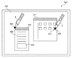
各ユニットがそれぞれ、上述の動作をすることによって、図24に示すような、表示画像に対する指示具4の操作が可能となる。すなわち、指示具4内のフラッシュメモリ303に対して、連続した一連の動作にてデータの転送を行なうことが可能で、かつそのデータのセキュリティが確保されている。
When each unit performs the above-described operation, the
上記連続した一連の動作とは例えば次のようなものである。まず、フラッシュメモリ303からホストコンピュータ6に転送したい場合には、図24の左側に示したウィンドウを介して操作することができる。すなわち、指示具4で任意の位置404をファイル転送を指示するとウィンドウ405が開き、このとき初めての転送モードであれば、サイン認証を要求するサイン認証領域407が表示される。指示具4のフラッシュメモリ303のファイル一覧は406に表示されうるが、このときはユーザーにとっては認識不可能な表示となる。
The continuous series of operations is as follows, for example. First, when it is desired to transfer data from the
次にサイン認証領域407に登録ユーザーのサインを入力するとファイル一覧406が正しく表示されるようになる。なお、転送モードが2回目以上で、認証が許可されているならば、指示具4でファイル転送した指示した時点で、サイン認証領域407を省いたファイル一覧を表示したウィンドウが表示されることになる。
Next, when a registered user's signature is input to the
一方、図24の表示領域402の右側に示したホストコンピュータ6のデータを指示具4のフラッシュメモリ303に転送する場合には、転送モードが、ログイン後初回であるならば先述の通り認証モードの動作が実行される。転送モードが2回目以降であるならば、ウィンドウ411内のアイコン410を指示具4で指示することにより、ただちに対応するファイルがホストコンピュータ6から指示具4への転送が実行される。このとき、転送期間中は、画面に視覚的に操作者に転送状況がわかるようにインジケータを表示させてもよい。あるいは指示具4にインジケータを表示させてもよい。
On the other hand, when the data of the host computer 6 shown on the right side of the
以上のように構成することによって、パーソナルコンピュータなどのホストコンピュータ6から指示具4等の別の情報処理機器へのデータ転送を容易に行なうことが可能となり、さらに指示具4に保存されているデータのセキュリティを確保することができる。
By configuring as described above, it becomes possible to easily transfer data from the host computer 6 such as a personal computer to another information processing device such as the
なお、上述した座標入力装置8は光学方式によるものであったが、指示具4が画面上でどの位置を指示したかを検出可能で、かつホストコンピュータ6へ検出した座標値を送信することによって各種のアプリケーションの操作が可能であるならば、必ずしも光学方式に限定されるわけではなく、他の方式、例えば超音波方式、電磁誘導方式、電磁授受方式、静電結合方式、抵抗膜方式であってもよい。
Although the coordinate
また、指示具4内のフラッシュメモリ303に対する認証方式は、ペン型の入力装置を指示具4として用いることから、操作性のよいサイン認証方式を用いたが、使用する個人が特定できれば他の方式でもよく、例えば、眼球内にある虹彩(アイリス)のパターン画像をデータ化し、予め登録してある本人のアイリスデータと比較照合することにより個人を特定する虹彩認識、声の周波数パターンをデータ化して、予め登録してある本人のデータと比較照合して個人を特定する声紋認識、顔画像から特徴点を抽出し、その間隔や場所といった幾何学的な関係情報から認識する顔画像認識であってもよい。いずれもアプリケーションの操作を行なう指示具に認証機能を搭載することで、専用の認証用装置に持ちかえるなどの手間がなく操作性に優れた認証動作を行なうことができる。
Further, the authentication method for the
(座標入力装置をマウスで構成する場合)
他の実施形態として、座標入力装置8として無線通信方式マウスを用いた場合について説明する。無線通信方式マウスとは、ホストコンピュータ6と入力装置であるマウス本体が無線で接続されており、赤外線あるいは電波にて通信が行なわれるものである。
(When the coordinate input device is configured with a mouse)
As another embodiment, a case where a wireless communication system mouse is used as the coordinate
この場合の情報処理システムのハードウェア構成を図25に示す。ただし、上述の実施形態における構成要素と同様の構成要素には共通の参照番号を付す。 The hardware configuration of the information processing system in this case is shown in FIG. However, the same reference numerals are given to the same components as those in the above-described embodiment.
座標入力装置は、マウスユニット20と制御ユニット21から構成される。マウスユニット20には、フラッシュメモリ505が内蔵されており、このフラッシュメモリ505へのアクセス制御は指紋認証方式で行なう。指紋による個人認証は、登録された指紋と入力された指紋とを比較照合し、十分に一致していると判断された場合に本人として判定するものである。指紋の照合アルゴリズムは、指紋模様に含まれる特徴点(隆線の端点や分岐点)の方向や位置関係などの特徴点相互間の相関関係を照合するものであり、高い指紋照合能力を持っている。指紋認証は、ROM507に格納してある指紋認証用エンジンプログラムおよび指紋認証用データベースによって実現され、これはイメージセンサおよび処理回路などから構成される指紋認証回路512に入力された指紋データに対して行われる。このときの動作を上述の実施形態と同様に「認証モード」とよぶことにする。
The coordinate input device includes a
認証モードにて指紋認証の動作が行なわれ、操作者の指紋認証が終了し、マウスユニット20のフラッシュメモリ505へのアクセスが許可されたならば、フラッシュメモリ505からのホストコンピュータ6への転送か、あるいはホストコンピュータ6からフラッシュメモリ505への転送かを操作者が選択することができる。この動作を先述の実施形態と同様に「転送モード」とよび、マウスユニット20側から見たときに、ホストコンピュータ6へ転送する場合は「送信モード」、ホストコンピュータ6から転送する場合を「受信モード」とすると、その切替えは、マウスユニット20のスイッチSW1(501)、SW2(502)、SW3(503)に割り当てられており、このスイッチを押すことによって適宜切替え動作をさせることができる。
When the fingerprint authentication operation is performed in the authentication mode, the fingerprint authentication of the operator is completed, and the access to the
このように構成することによって、先に説明した実施形態と同様に表示装置7によって表示されているカーソルを操作して転送したいウィンドウを指示したり、表示装置7によって表示されているアイコンを指示することによって、マウスユニット20内のフラッシュメモリ505とホストコンピュータ6の間でのデータ転送が実行される。
With this configuration, the cursor displayed on the
すなわち、以上のように構成することによって、パーソナルコンピュータなどの情報処理装置を操作する入力装置としてマウスを構成した場合でも、その情報処理装置へのデータ転送を容易に行なうことが可能となり、さらにマウスに保存されているデータのセキュリティも確保できるという先述の実施形態と同様の効果を得ることができる。 That is, with the above configuration, even when a mouse is configured as an input device for operating an information processing apparatus such as a personal computer, data transfer to the information processing apparatus can be easily performed. The same effect as that of the above-described embodiment that the security of the data stored in the file can be secured can be obtained.
(その他の実施形態)
これまで説明してきた座標入力装置を含む情報処理システムは、これを会議室などに常設して会議システムとして利用する場合などのように、入力指示具も会議室などに据置きにする場合には、使用者の認証データをあらかじめ認証用データベースに登録しておく必要がある。そして、この場合は複数の操作者が入力指示具を交互に交替して使用することとなる。そのときは、登録した使用者に対して、入力指示具内のフラッシュメモリの使用領域を割り当てることで効率的なデータのアクセスが可能となり操作者にとって快適なデータ転送が可能となる。
(Other embodiments)
When the information processing system including the coordinate input device described so far is used as a conference system by permanently installing it in a conference room, etc. User authentication data must be registered in the authentication database in advance. In this case, a plurality of operators will alternately use the input instruction tool. At that time, by assigning the use area of the flash memory in the input instruction tool to the registered user, it is possible to access data efficiently, and data transfer comfortable for the operator is possible.
また、1台の表示装置を有する情報処理装置に対して、複数の入力指示具を使用する場合には、表示装置に表示される情報を共有してそれぞれの使用者がこの入力指示具を持参して個人専用に使用する使用形態が考えられる。例えばノートパソコンなどを持参して会議などに参加する場合に、入力指示具を、その会議室のホストコンピュータにネットワークが接続されていなくても持参したノートパソコンとホストコンピュータ間のデータ転送媒体として利用することができる。この場合であっても、各使用者はホストコンピュータのポートに接続することなく、しかも表示情報に対してダイレクトな操作でデータ転送が可能なので、操作性に優れ使い勝手のよい情報処理装置となる。 In addition, when a plurality of input instruction tools are used for an information processing apparatus having one display device, information displayed on the display device is shared and each user brings this input instruction tool. Thus, a usage form for personal use can be considered. For example, when you bring a notebook computer, etc. to participate in a meeting, the input instruction tool is used as a data transfer medium between the notebook computer and the host computer that you bring even if the network is not connected to the host computer in the meeting room. can do. Even in this case, each user can transfer data to the display information by a direct operation without connecting to the port of the host computer, so that the information processing apparatus is excellent in operability and easy to use.
ところで、複数の入力指示具がある場合には、各指示具のフラッシュメモリからホストコンピュータに転送されたデータには、転送後もアクセス権などでセキュリティを考慮したファイルシステムとすることが好ましい。特に共有システムで使用する場合には、転送したデータに対して不特定多数のアクセスが考えられる。また、ホストコンピュータ側でのユーザー許可が何らかの手段により破られて、データの改竄や不正コピーなどの処理が可能となることは好ましくない。そこで、本装置では、入力指示具のフラッシュメモリから転送されるファイルデータに対してIDを付加する手段を有する。すなわち、入力指示具のIDや使用者のIDを転送データの属性に付加してホストコンピュータ6に転送することによって、様々なデータに対するアクセスを制御することが可能となる。 By the way, when there are a plurality of input indicating tools, it is preferable that the data transferred from the flash memory of each pointing tool to the host computer should have a file system that takes security into consideration with the access right after transfer. In particular, when used in a shared system, an unspecified number of accesses to the transferred data can be considered. In addition, it is not preferable that the user permission on the host computer side is broken by some means, and processing such as data tampering or unauthorized copying becomes possible. Therefore, this apparatus has means for adding an ID to the file data transferred from the flash memory of the input instruction tool. That is, it is possible to control access to various data by adding the input instruction tool ID and the user ID to the transfer data attribute and transferring them to the host computer 6.
上記IDがファイル属性に付加される処理は、指示具内のCPUによって実行され、フラッシュメモリに転送されることとなる。付加されるIDは、各ペン(指示具)に対して一対一に設定されていて、このペンに対する固有のIDをペンIDと呼ぶことにすると、ペンIDは予めそのペン内のROMに保存されており、適宜CPUから読出しが行なわれる。 The process of adding the ID to the file attribute is executed by the CPU in the pointing tool and transferred to the flash memory. The ID to be added is set one-to-one for each pen (indicator). If the unique ID for this pen is called a pen ID, the pen ID is stored in advance in the ROM in the pen. Read from the CPU as appropriate.
ペンからホストコンピュータに転送するファイルに対して、ホストコンピュータのアプリケーションではファイルの属性のチェックが行なわれる。そして、ペンIDが、ファイル属性に付加されていた場合には、アプリケーションに使用している複数のペンのうちどのペンから転送されたファイルであるかを判別することが可能となる。さらに上記に加えて、先述した認証動作を実行した操作者のIDが転送ファイルの属性に付加されることによって、ホストコンピュータでは転送されたデータにユーザーのID情報が付加されているので、どのユーザーがデータを転送したのかを判別することが可能となる。 For the file transferred from the pen to the host computer, the host computer application checks the file attributes. When the pen ID is added to the file attribute, it is possible to determine from which pen among the plurality of pens used in the application the file has been transferred. In addition to the above, the ID of the operator who executed the above-described authentication operation is added to the attribute of the transfer file, so that the user ID information is added to the transferred data in the host computer. It is possible to determine whether the data has been transferred.
このようにファイル属性にペンIDあるいはユーザーIDを付加することによって、ホストコンピュータでは、例えば、ファイルに対する閲覧、修正、加筆などのアクセス制御をペン単位あるいはユーザー単位で制御することができるため、優れたセキュリティ機能を有することとなる。 By adding the pen ID or user ID to the file attribute in this way, the host computer can control access control such as browsing, correction, and writing on the file in units of pens or in units of users. It will have a security function.
一方で、ホストコンピュータから、ペンにファイルが転送された場合は、ペン側では、転送されたファイル属性をチェックして、既にペンIDあるいはペンユーザーIDが付属していないかを確認する。そして、ホストコンピュータからの受信データがIDなしデータの場合には、新たにファイル属性にIDを付加する。また、すでに別のペンのIDやユーザーIDが付加されていた場合には、時系列データとして保存してある履歴情報を更新し、IDの更新作業を行なう。このように、ホストコンピュータ6から転送されたファイルに対してもIDの履歴情報を更新し、ペンおよびユーザーの情報を監視することで、データの二次的な使用を有効的に効率化することが可能となる。 On the other hand, when a file is transferred from the host computer to the pen, the pen side checks the transferred file attribute to confirm whether the pen ID or the pen user ID has already been attached. If the data received from the host computer is data without ID, an ID is newly added to the file attribute. If another pen ID or user ID has already been added, the history information stored as time-series data is updated to update the ID. As described above, the ID history information is updated even for the file transferred from the host computer 6 and the pen and user information is monitored to effectively improve the secondary use of the data. Is possible.
(入力指示具の記憶手段が着脱可能な構成とする場合)
先述の実施形態では、使用者がそれぞれ専用の入力指示具を使用して、共有の表示装置および情報処理装置を使用する使用形態について説明した。しかしながら、持ち運びする記憶媒体としては、小型軽量である方が好ましいことは言うまでもない。したがって、以下では、入力指示具の構成を記憶手段と入力指示具本体とを着脱可能な構成にする場合について説明する。
(When the input indicator storage means is detachable)
In the above-described embodiment, a usage pattern in which a user uses a shared display device and an information processing device using a dedicated input instruction tool has been described. However, it goes without saying that it is preferable that the storage medium to be carried is small and light. Therefore, in the following, the case where the configuration of the input pointing tool is configured so that the storage means and the input pointing tool main body are detachable will be described.
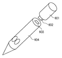
共有ディスプレイを用いた会議などを行なう場合に、あらかじめ資料を作成して電子文書として持参することが考えられるが、指示具にデータを保存して会議などに参加することが可能ではあることは先述の通りである。しかし、本実施形態の座標入力装置を含む情報処理システムを会議室などに常設して使用する場合には、指示具としての入力ペンは記憶装置を有しているので入力ペンも常設した情報処理装置に付属して据置きとしたい場合が考えられる。したがって、記憶手段を着脱可能とすることで、個人のデータを別の場所などで手持ちのコンピュータに該記憶手段であるメモリをシリアルポートなどに接続して各種データを移動させて、情報処理システムを使用するときに指示具本体に接続して使用することが可能な構成とした。このような構成にすることによって、先に説明したのと同様の効果を得ることができる。 When conducting a meeting using a shared display, it is conceivable to prepare a document in advance and bring it as an electronic document. However, as mentioned above, it is possible to save data in the pointing device and participate in a meeting. It is as follows. However, when the information processing system including the coordinate input device according to the present embodiment is permanently installed in a conference room or the like, the input pen as the pointing tool has a storage device, and thus the information processing in which the input pen is also permanently installed. There may be a case where it is desired to leave it attached to the device. Therefore, by making the storage means detachable, the personal data can be transferred to a computer on hand at another location by connecting the memory as the storage means to a serial port etc. It was set as the structure which can be used by connecting with an indicator main body when using it. By adopting such a configuration, the same effect as described above can be obtained.
図26にメモリ部分を着脱可能な指示具の概略構成図を示す。この指示具は、フラッシュメモリを内蔵する筐体(メモリ部分)601と先述のような駆動回路やスイッチを有する筐体604とを、コネクタ602と603とによって接続可能な構成となっている。コネクタ602は、例えばパーソナルコンピュータのシリアルポートと共通の接続仕様となっている。したがって、情報処理システムの使用、不使用に関係なく汎用のメモリデバイスとして使用することが可能である。一方で入力ペン本体である604は、記憶手段はないが、単体で座標入力装置の入力ペン(指示具)として使用することが可能である。
FIG. 26 shows a schematic configuration diagram of an indicating tool to which the memory portion can be attached and detached. This indicator has a configuration in which a housing (memory portion) 601 containing a flash memory and a
以上の構成にすることによって、先に説明した実施形態と同様に記憶手段を汎用デバイスとして使用可能としつつ、入力ペンと接続することによって、ホストコンピュータにデータ転送が可能となる。 With the above configuration, the storage unit can be used as a general-purpose device as in the above-described embodiment, and data can be transferred to the host computer by connecting to the input pen.
以上、本発明の実施形態を詳述したが、本発明は、複数の機器から構成されるシステムに適用してもよいし、また、一つの機器からなる装置に適用してもよい。 As mentioned above, although embodiment of this invention was explained in full detail, this invention may be applied to the system comprised from several apparatuses, and may be applied to the apparatus which consists of one apparatus.
なお、本発明は、前述した実施形態の機能を実現するソフトウェアのプログラムを、システムあるいは装置に直接あるいは遠隔から供給し、そのシステムあるいは装置のコンピュータがその供給されたプログラムコードを読み出して実行することによっても達成される。その場合、プログラムの機能を有していれば、その形態はプログラムである必要はない。 In the present invention, a software program that realizes the functions of the above-described embodiments is directly or remotely supplied to a system or apparatus, and the computer of the system or apparatus reads and executes the supplied program code. Is also achieved. In that case, as long as it has the function of a program, the form does not need to be a program.
従って、本発明の機能処理をコンピュータで実現するために、そのコンピュータにインストールされるプログラムコード自体およびそのプログラムを格納した記憶媒体も本発明を構成することになる。つまり、本発明の特許請求の範囲には、本発明の機能処理を実現するためのコンピュータプログラム自体、およびそのプログラムを格納した記憶媒体も含まれる。 Therefore, in order to realize the functional processing of the present invention with a computer, the program code itself installed in the computer and the storage medium storing the program also constitute the present invention. In other words, the claims of the present invention include the computer program itself for realizing the functional processing of the present invention and a storage medium storing the program.
その場合、プログラムの機能を有していれば、オブジェクトコード、インタプリタにより実行されるプログラム、OSに供給するスクリプトデータ等、プログラムの形態を問わない。 In this case, the program may be in any form as long as it has a program function, such as an object code, a program executed by an interpreter, or script data supplied to the OS.
プログラムを供給するための記憶媒体としては、例えば、フレキシブルディスク、ハードディスク、光ディスク、光磁気ディスク、MO、CD−ROM、CD−R、CD−RW、磁気テープ、不揮発性のメモリカード、ROM、DVD(DVD−ROM,DVD−R)などがある。 As a storage medium for supplying the program, for example, flexible disk, hard disk, optical disk, magneto-optical disk, MO, CD-ROM, CD-R, CD-RW, magnetic tape, nonvolatile memory card, ROM, DVD (DVD-ROM, DVD-R).
その他、プログラムの供給方法としては、クライアントコンピュータのブラウザを用いてインターネットのホームページに接続し、そのホームページから本発明のコンピュータプログラムそのもの、もしくは圧縮され自動インストール機能を含むファイルをハードディスク等の記憶媒体にダウンロードすることによっても供給できる。また、本発明のプログラムを構成するプログラムコードを複数のファイルに分割し、それぞれのファイルを異なるホームページからダウンロードすることによっても実現可能である。つまり、本発明の機能処理をコンピュータで実現するためのプログラムファイルを複数のユーザに対してダウンロードさせるWWWサーバも、本発明のクレームに含まれるものである。 As another program supply method, a client computer browser is used to connect to an Internet homepage, and the computer program of the present invention itself or a compressed file including an automatic installation function is downloaded from the homepage to a storage medium such as a hard disk. Can also be supplied. It can also be realized by dividing the program code constituting the program of the present invention into a plurality of files and downloading each file from a different homepage. That is, a WWW server that allows a plurality of users to download a program file for realizing the functional processing of the present invention on a computer is also included in the claims of the present invention.
また、本発明のプログラムを暗号化してCD−ROM等の記憶媒体に格納してユーザに配布し、所定の条件をクリアしたユーザに対し、インターネットを介してホームページから暗号化を解く鍵情報をダウンロードさせ、その鍵情報を使用することにより暗号化されたプログラムを実行してコンピュータにインストールさせて実現することも可能である。 In addition, the program of the present invention is encrypted, stored in a storage medium such as a CD-ROM, distributed to users, and key information for decryption is downloaded from a homepage via the Internet to users who have cleared predetermined conditions. It is also possible to execute the encrypted program by using the key information and install the program on a computer.
また、コンピュータが、読み出したプログラムを実行することによって、前述した実施形態の機能が実現される他、そのプログラムの指示に基づき、コンピュータ上で稼動しているOSなどが、実際の処理の一部または全部を行い、その処理によっても前述した実施形態の機能が実現され得る。 In addition to the functions of the above-described embodiments being realized by the computer executing the read program, the OS running on the computer based on the instruction of the program is a part of the actual processing. Alternatively, the functions of the above-described embodiment can be realized by performing all of the processes.
さらに、記憶媒体から読み出されたプログラムが、コンピュータに挿入された機能拡張ボードやコンピュータに接続された機能拡張ユニットに備わるメモリに書き込まれた後、そのプログラムの指示に基づき、その機能拡張ボードや機能拡張ユニットに備わるCPUなどが実際の処理の一部または全部を行い、その処理によっても前述した実施形態の機能が実現される。 Furthermore, after the program read from the storage medium is written to a memory provided in a function expansion board inserted into the computer or a function expansion unit connected to the computer, the function expansion board or The CPU or the like provided in the function expansion unit performs part or all of the actual processing, and the functions of the above-described embodiments are realized by the processing.
Claims (6)
データの書き換えが可能なメモリ媒体を備えた指示具と、
前記表示装置による画像の表示面に設けた入力領域内における前記指示具による操作に係る情報を入力する入力装置と、
前記入力装置によって入力された情報に応じた制御処理を行うホスト装置と、
を有する情報処理システムであって、
前記入力装置は、
前記指示具の所定の操作によって発行される前記メモリ媒体−前記ホスト装置間におけるファイル転送の要求を検出した場合に、前記メモリ媒体に対するアクセスのための認証を行う認証モードの動作を行うか否かを、前記ホスト装置からの信号に基づいて判断する判断手段と、
前記判断手段により前記認証モードの動作を行うと判断された場合に、前記指示具により入力された情報を認証用データに変換する変換手段と、
前記変換手段により得られた前記認証用データを前記指示具に送信する送信手段と、
を有し、
前記指示具は、
前記入力装置より受信した前記認証用データに基づき認証処理を行う認証手段
を有することを特徴とする情報処理システム。 A display device for displaying an image;
An indicator having a memory medium capable of rewriting data;
An input device for inputting information related to an operation by the pointing tool in an input region provided on a display surface of an image by the display device;
A host device that performs control processing according to information input by the input device;
An information processing system having
The input device is:
Said memory medium is issued by a predetermined operation of the pointing device - whether when it detects a request for file transfer between the host device performs the operation of the authentication mode for authentication for access to said memory medium Determining means for determining based on a signal from the host device;
Conversion means for converting the information input by the pointing device into authentication data when it is determined by the determination means to perform the operation in the authentication mode;
Transmitting means for transmitting the authentication data obtained by the converting means to the pointing device;
Have
The indicator is
An information processing system comprising authentication means for performing authentication processing based on the authentication data received from the input device.
データの書き換えが可能なメモリ媒体を備えた指示具と、
前記指示具によって入力された情報に応じた制御処理を行うホスト装置と、
にそれぞれ接続され、前記表示装置による画像の表示面に設けた入力領域内における前記指示具による操作に係る情報を入力する入力装置の制御方法であって、
前記指示具の所定の操作によって発行される前記メモリ媒体−前記ホスト装置間におけるファイル転送の要求を検出した場合に、前記メモリ媒体に対するアクセスのための認証を行う認証モードの動作を行うか否かを、前記ホスト装置からの信号に基づいて判断する判断ステップと、
前記判断ステップにおいて前記認証モードの動作を行うと判断された場合に、前記指示具により入力された情報を認証用データに変換する変換ステップと、
前記変換ステップで得られた前記認証用データを前記指示具に送信する送信ステップと、
を有することを特徴とする入力装置の制御方法。 A display device for displaying an image;
An indicator having a memory medium capable of rewriting data;
A host device that performs control processing according to information input by the pointing tool;
To be connected, a control method of an input device for inputting information according to the operation by the pointing device on the display device input area provided on the display surface of the image by,
Said memory medium is issued by a predetermined operation of the pointing device - whether when it detects a request for file transfer between the host device performs the operation of the authentication mode for authentication for access to said memory medium Determining step based on a signal from the host device;
A conversion step of converting information input by the pointing tool into authentication data when it is determined in the determination step that the operation in the authentication mode is performed;
A transmission step of transmitting the authentication data obtained in the conversion step to the indicator;
A control method for an input device, comprising:
データの書き換えが可能なメモリ媒体を備えた指示具と、
前記指示具によって入力された情報に応じた制御処理を行うホスト装置と、
にそれぞれ接続され、前記表示装置による画像の表示面に設けた入力領域内における前記指示具による操作に係る情報を入力する入力装置によって実行される制御プログラムであって、
前記指示具の所定の操作によって発行される前記メモリ媒体−前記ホスト装置間におけるファイル転送の要求を検出した場合に、前記メモリ媒体に対するアクセスのための認証を行う認証モードの動作を行うか否かを、前記ホスト装置からの信号に基づいて判断する判断ステップ、
前記判断ステップにおいて前記認証モードの動作を行うと判断された場合に、前記指示具により入力された情報を認証用データに変換する変換ステップ、
前記変換ステップで得られた前記認証用データを前記指示具に送信する送信ステップ、
を前記入力装置に実行させるための制御プログラム。 A display device for displaying an image;
An indicator having a memory medium capable of rewriting data;
A host device that performs control processing according to information input by the pointing tool;
To be connected respectively, a said display device an image control program thus executed to an input device for inputting information according to the operation by the pointing device at the display surface provided input region of by,
Said memory medium is issued by a predetermined operation of the pointing device - whether when it detects a request for file transfer between the host device performs the operation of the authentication mode for authentication for access to said memory medium Determining step based on a signal from the host device,
A conversion step of converting information input by the pointing tool into authentication data when it is determined in the determination step that the operation in the authentication mode is performed;
A transmitting step of transmitting the authentication data obtained in the converting step to the pointing device ;
A control program for causing the input device to execute .
データの書き換えが可能なメモリ媒体を備えた指示具と、
前記指示具によって入力された情報に応じた制御処理を行うホスト装置と、
にそれぞれ接続され、前記表示装置による画像の表示面に設けた入力領域内における前記指示具による操作に係る情報を入力する入力装置であって、
前記指示具の所定の操作によって発行される前記メモリ媒体−前記ホスト装置間におけるファイル転送の要求を検出した場合に、前記メモリ媒体に対するアクセスのための認証を行う認証モードの動作を行うか否かを、前記ホスト装置からの信号に基づいて判断する判断手段と、
前記判断手段により前記認証モードの動作を行うと判断された場合に、前記指示具により入力された情報を認証用データに変換する変換手段と、
前記変換手段により得られた前記認証用データを前記指示具に送信する送信手段と、
を有することを特徴とする入力装置。 A display device for displaying an image;
An indicator having a memory medium capable of rewriting data;
A host device that performs control processing according to information input by the pointing tool;
To be connected, an input equipment for inputting information relating to the operation by the pointing device in the input area provided on the display surface of the image by the display device,
Said memory medium is issued by a predetermined operation of the pointing device - whether when it detects a request for file transfer between the host device performs the operation of the authentication mode for authentication for access to said memory medium Determining means for determining based on a signal from the host device;
Conversion means for converting the information input by the pointing device into authentication data when it is determined by the determination means to perform the operation in the authentication mode;
Transmitting means for transmitting the authentication data obtained by the converting means to the pointing device;
An input device comprising:
Priority Applications (1)
| Application Number | Priority Date | Filing Date | Title |
|---|---|---|---|
| JP2004191459A JP4565621B2 (en) | 2004-06-29 | 2004-06-29 | Information processing system |
Applications Claiming Priority (1)
| Application Number | Priority Date | Filing Date | Title |
|---|---|---|---|
| JP2004191459A JP4565621B2 (en) | 2004-06-29 | 2004-06-29 | Information processing system |
Publications (2)
| Publication Number | Publication Date |
|---|---|
| JP2006012040A JP2006012040A (en) | 2006-01-12 |
| JP4565621B2 true JP4565621B2 (en) | 2010-10-20 |
Family
ID=35779207
Family Applications (1)
| Application Number | Title | Priority Date | Filing Date |
|---|---|---|---|
| JP2004191459A Expired - Fee Related JP4565621B2 (en) | 2004-06-29 | 2004-06-29 | Information processing system |
Country Status (1)
| Country | Link |
|---|---|
| JP (1) | JP4565621B2 (en) |
Families Citing this family (2)
| Publication number | Priority date | Publication date | Assignee | Title |
|---|---|---|---|---|
| JP4762831B2 (en) | 2006-08-28 | 2011-08-31 | 東芝テック株式会社 | Electronic blackboard |
| JP5668622B2 (en) * | 2010-12-16 | 2015-02-12 | キヤノンマーケティングジャパン株式会社 | Printing system, image processing apparatus, control method, and program thereof |
Citations (2)
| Publication number | Priority date | Publication date | Assignee | Title |
|---|---|---|---|---|
| JP2002055768A (en) * | 2000-08-09 | 2002-02-20 | Sharp Corp | Pen type recording medium |
| JP2004070831A (en) * | 2002-08-08 | 2004-03-04 | Sony Corp | Input device |
-
2004
- 2004-06-29 JP JP2004191459A patent/JP4565621B2/en not_active Expired - Fee Related
Patent Citations (2)
| Publication number | Priority date | Publication date | Assignee | Title |
|---|---|---|---|---|
| JP2002055768A (en) * | 2000-08-09 | 2002-02-20 | Sharp Corp | Pen type recording medium |
| JP2004070831A (en) * | 2002-08-08 | 2004-03-04 | Sony Corp | Input device |
Also Published As
| Publication number | Publication date |
|---|---|
| JP2006012040A (en) | 2006-01-12 |
Similar Documents
| Publication | Publication Date | Title |
|---|---|---|
| JP4442877B2 (en) | Coordinate input device and control method thereof | |
| CN101375297B (en) | Interactive input system | |
| CN1322329B (en) | Imput device using scanning sensors | |
| KR101872426B1 (en) | Depth-based user interface gesture control | |
| US8022928B2 (en) | Free-space pointing and handwriting | |
| US8957864B2 (en) | Coordinate input apparatus and method | |
| US20140141887A1 (en) | Generating position information using a video camera | |
| CN105824431A (en) | Information input device and method | |
| JP2010537302A (en) | Device worn on a finger and method of use thereof | |
| TW201823935A (en) | Hand-written information processing apparatus, hand-written information processing method and hand-written information processing program | |
| CN103929603A (en) | Image Projection Device, Image Projection System, And Control Method | |
| JP2020502608A (en) | Portable communication terminal, directional input unit and related method | |
| KR101512239B1 (en) | System and method for transfering content among devices using touch command and unusual touch | |
| JP4455185B2 (en) | Presentation system, control method therefor, program, and storage medium | |
| CN103543825B (en) | Camera cursor system | |
| WO2021004413A1 (en) | Handheld input device and blanking control method and apparatus for indication icon of handheld input device | |
| JP4565621B2 (en) | Information processing system | |
| CN101714032A (en) | Device for processing optical control information | |
| JP2006301740A (en) | Coordinate input device and its control method, and program | |
| EP1892608A1 (en) | Gesture recognition system | |
| CN101504580A (en) | Optical touch screen and its touch pen | |
| US20140055354A1 (en) | Multi-mode interactive projection system, pointing device thereof, and control method thereof | |
| CN102298471A (en) | Optical touch screen | |
| KR101491648B1 (en) | System and Method for remote control using camera | |
| KR101036452B1 (en) | Contactless keypad and realization method thereof |
Legal Events
| Date | Code | Title | Description |
|---|---|---|---|
| A621 | Written request for application examination |
Free format text: JAPANESE INTERMEDIATE CODE: A621 Effective date: 20070611 |
|
| RD03 | Notification of appointment of power of attorney |
Free format text: JAPANESE INTERMEDIATE CODE: A7423 Effective date: 20070611 |
|
| A977 | Report on retrieval |
Free format text: JAPANESE INTERMEDIATE CODE: A971007 Effective date: 20100225 |
|
| A131 | Notification of reasons for refusal |
Free format text: JAPANESE INTERMEDIATE CODE: A131 Effective date: 20100301 |
|
| A521 | Request for written amendment filed |
Free format text: JAPANESE INTERMEDIATE CODE: A523 Effective date: 20100428 |
|
| TRDD | Decision of grant or rejection written | ||
| A01 | Written decision to grant a patent or to grant a registration (utility model) |
Free format text: JAPANESE INTERMEDIATE CODE: A01 Effective date: 20100730 |
|
| A01 | Written decision to grant a patent or to grant a registration (utility model) |
Free format text: JAPANESE INTERMEDIATE CODE: A01 |
|
| A61 | First payment of annual fees (during grant procedure) |
Free format text: JAPANESE INTERMEDIATE CODE: A61 Effective date: 20100802 |
|
| R150 | Certificate of patent or registration of utility model |
Free format text: JAPANESE INTERMEDIATE CODE: R150 |
|
| FPAY | Renewal fee payment (event date is renewal date of database) |
Free format text: PAYMENT UNTIL: 20130813 Year of fee payment: 3 |
|
| LAPS | Cancellation because of no payment of annual fees |